S5002321

260 MSeckć Żehrovicc in Bohemia
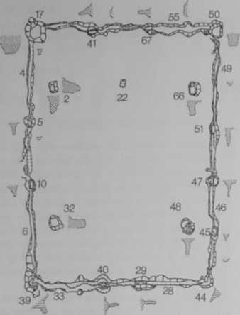


Fig. 2. Interpretation of the ground plan ofbuilding 0/87-11.
BBg 0
Fig. 1. Ground plan ofbuilding 0/87-1.
ponents of the roof structure are the collar plates. They were supported by the four vertical posts of the inner structure. Connected by tie collar beams, they contributed significantly to the overall rigidity of the building. It can be inferred from the elongated shape of the plan that the ends of the collar plates reached slightly beyond the joints with the tie collar beams. The protruding ends were used for jointing the collar plates of the shorter end sides of the hipped roof. A closed rec-tangular collar madę of the individual collar plates was thus formed which reąuired support in the carners (cf. Ondrej 1953, 119). As traces of cor-responding vertical supports are missing in the plan it is assumed that braces were used. Not only that but their use has to be taken into considera-tion in places where the span of timbers is between 6-10 m, i.e. the tie collar beams and the ridge piece (Ondrej 1953,96). The question of braces remains open to discussion. The evidence shows this par-ticular element to have been used as late as the Roman Iron Age (Zippelius 1954,47, Abb. 3e). Its existence in the Iron Age is considered probable by some scholars (e.g. Pautreau 1988, 52, Fig. 7; Fil gis 1993,110-111, Abb. 31-32) or only possible (Audouze - Buchsenschutz 1989, Fig. 26), while others doubt it (Villes 1981, 74,92). On the other hand, it is an elementary way of making the struć-tures morę rigid, and it is hard to imagine that it had not been in use at that time, considering the wide rangę of, sometimes most elaborate, car-pentry techniąues evidenced in the Iron Age or even earlier. It is the author’s opinion that the only prerequisite for the introduction of braces into building construction was the knowledge of mortise and tenon jointing or lap jointing. Both techniques had been mastered in periods much earlier than the one we are considering (see Zippelius 1954).
The roof structure was complete with rafters. They rested on the ridge piece and on the collar plates, their Iow ends sitting on the wali plates of the outer walls. The roofing materiał itself may have been madę of thatch or shingles. In the former case, as shown by the rcconstruction (Fig. 3), only thatch from barley straw can be considered. Rye or oat straw may be disregarded owing to the very limited production of these crops throughout the territory of Boiohaemum in the La Tene period (see Ciżm&r 1989, 98; Motykovś * Drda - Rybovś 1990, 365). Wheat straw is un-suitable for this purpose. A rough estimate of the quantity of straw needed can be achieved by a calculation based, admittedly, on a contem-porary standard (MSN 1926, 362). Given a minimum number of 9 thatches per 1 m2 the hipped roof of an area of 282 m2 would need a to tal of 2538 thatches weighing in to tal over 6.75 tons. Added to the load exerted by the roof cover should also be the load of the weight of the roof structure itself.
The building design must have taken into con-sideration other factors as well, above all the load
P. Drela: Beconstruction of the structure 0/87
exerted by snów and wind. The wind pressure could have reached 70-75 kg/m2 provided the height of the reconstructed roof reached around 8 m above ground level. The westerly winda which prevail in this part of the country would expose the aide of the hipped roof to a load of up to 7000 kg. Snów caused similar problem* Although it did not play a part on the sborter, end sides of the hipped roof (their grade, according to the reconstruction, was c. 63), it could have added to both the indined longer sides (50-52) a weight of up to 45 kg/m2, i.e. a total of almost 9 tona (see Ondrej 1953, 98-99). How stable could the roof structure be under the above circumstances, according to the reconstruction? We must not forget the presence of precise workmanship, qu ality tim-ber, the depth of the foundations and a most rigid structure which was of top quality both in its conception and construction. If the weight of the roof structure itself (30-50 kg/m2 of the plan area after Ondrej 1953,98), the roof cover and possiUe snów cover were totalled then the load of the structure in the vertical direction would rangę between c. 20.56 t to 23.84 t, i.e. c. max. 2.73 kg/cm2 of the supporting vertical poste These are capable, under eztreme conditions, of bearing a load as much as 329 timea higher, as hard oak-wood with standard moisture of 15% can with-stand maximum compressive stress of between 450-900 kg/cm2, acting para!lei with the wood fibres (Ondrej 1953, 15).
There is evidence from modem timea that pnnres the existence of roof structure* of similar design surviving without any signs of stability lass over several hundreds of years (Menel 1980, 340, Fig. 760). However, the life of building I in Mśec-kć 2ehrovice spanned, for reasons other than stability, but a fraction of such a period.
Possible esplanation of the process of destruction based on field obsarvations Building I, standing intact in perfect conditioo, caught firc under circumstances unesplained. The structure on fire, aided by the wind, collapsed as a whole and tumbled down on the eastem aide. The daub from the side walls, subject to various degrees of “firing", spread in a layer spilling out beyond the foundations of the eastem wali The poste of the supporting structure broke away at the foundations level and their remains burat or smouldered in the post hole* Fragment* of daub would fali into the gradually etnptied, burat out post holes, particularly in places with the greatest accumulation of daub. The burot ground was for some linie exposed to the effecto of the weather. Precipitation soaked the unequally bumt daub which would break down into smali lumpa and grains of pinkiah loam. The building ute prepara-

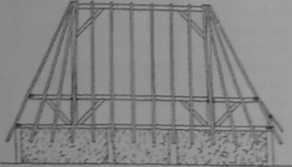

Fig. 3. Amnnmetric mUnctm of buiMing 0/87-1, its Motbem front and lateral vie«" from tbe west
tion for the construction of the later building lerelled up the ground. The layer of the bumt remains was turaed upside down, spread side-ways and further mechanically desintegrated. In the newiy lerelled ground large post holes were cxcavated for the construction of new foundations
How to reconstruct building U?
A doser inspection of the foundations needs to be taken to tealize that they form a scaled down
Wyszukiwarka
Podobne podstrony:
S5002322 Mśeckś Żehrovice in Bohemia 260 Fig. 2. Interpretationofthe ground plan of building 0/87-II
S5002308 124 Mgockć Żehrovice in Bohom iat » —im— ■ Fig. 86 feature 0/87: pit 48 (8). pit Fig. 87.
60954 S5002303 MSeckć Zehrovice in Bohomia 19 pottcry, 20-25 SBpropdit* rather Bylany* culture (cf.
S5002308 124 Mgockć Żehrovice in Bohom iat » —im— ■ Fig. 86 feature 0/87: pit 48 (8). pit Fig. 87.
S5002316 186 MSeckó 2chrovico in Bohemia if not as many as 6*6 (Biolonin 1992,186). This menns that
S5002315 204 MSockd 2ehrovico in Bohomin Fig. 109. Industrial features - • rccanst
51654 S5002318 190 MSeckó 2ehrovice in Bohemia and wool. The smali proportion of neo-natal and non-a
S5002296 chronotheąue NATALIE VENCLOVAMŚECKE ŹEHROVICE IN BOHEMIA AROHAEOLOGICAL BACKGROUND TO ACELT
więcej podobnych podstron