DSC07969
126
£. lYiirfriitnwTtii
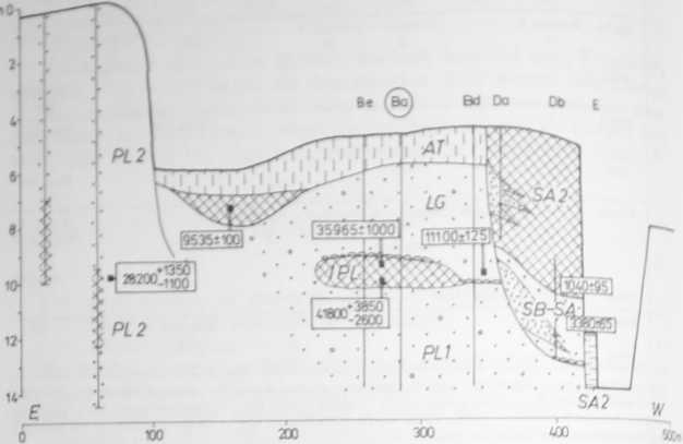
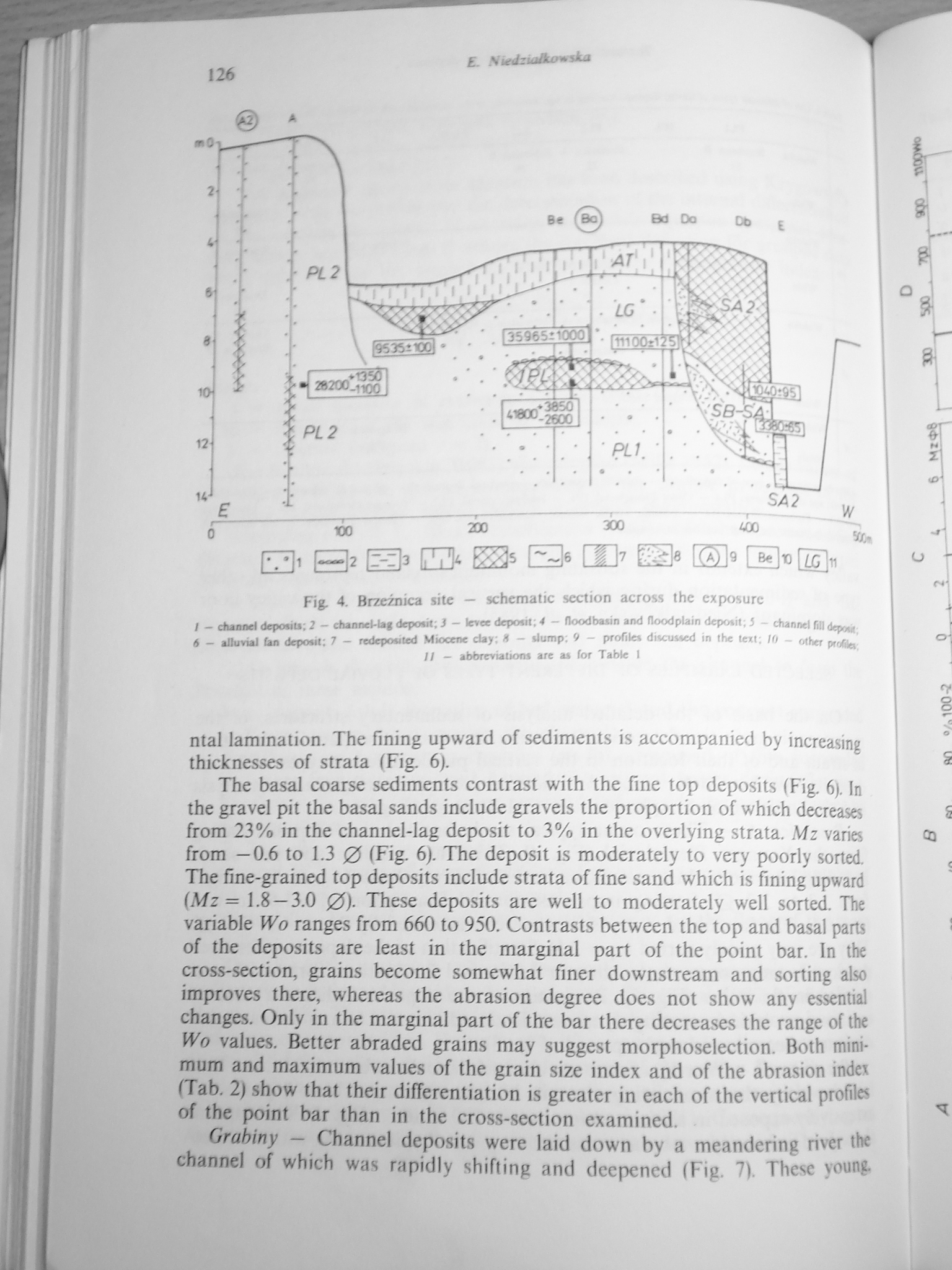
Fig. 4. Brzeźnica sile — schematic section across the exposure
EZli B* O 82* E3« a> El« [S]« S*®
r - Cłunnd dcpońtt; 2 - channeHag depoui; i - Inwe dcpoót; 4 - ffoodbaain and floodplain depotit; 5 - channel fili depoaf, i - alluml Im depowi: 7 - redepowted Miocene day; 8 - Uump. 9 - profile* diteuwed in the text; 10 - oiher prrffa il — abbreviai»oni are a* for Tabłe I
ntal lamination. The fining upward of sediments is accompanied by inereasing thicknesses of strata (Fig. 6).
The basal coarse sediments contrast with the fine top deposits (Fig. 6). In the gravel pit the basal sands include gravels the proportion of which decreases from 23% in the channel-lag deposit to 3% in the overlying strata. Mz varics from —0.6 to 1.3 0 (Fig. 6). The deposit is moderately to very poorly sorted. The fine-grained top deposits include strata of fine sand which is fining upward (Mz = 1.8—3.0 0). These deposits are well to moderately well sorted. The variable Wo ranges from 660 to 950. Contrasts between the top and basal parte of the deposits are least in the marginal part of the point bar. In the cross-section, grains become somewhat finer downstream and sorting also improves there, whereas the abrasion degree does not show any essential changes. Only in the marginal part of the bar there decreases the rangę of the Wo values. Better abraded grains may suggest morphoselection. Both minimum and maximum values of the grain size index and of the abrasion indet (Tab. 2) show that their differentiation is greater in each of the vertical profiles of the point bar than in the cross-section examined.
Grabiny — Channel deposits were laid down by a meandering river the channel of which was rapidly shifting and deepened (Fig. 7). These young.
Wyszukiwarka
Podobne podstrony:
DSC07970 o 3 A Fig. 5. Brzeźnica A site — profile , . ,h
DSC07980 (2) 138 £ NiediuJkowska strata and łenses of very fine sands (sites: Brzeźnica B, Podgrodzi
PA KF 126 £ dJ 15VAC Schemat wzmacniacza na lampie YC156
% o q,x/t,o,m/ S / 9 / l» »m/ t , 3 max max 9 t / siłę
image 16 sM$m* £ fó. .tys . jX*fVs! </-L" w • Schemat 3 Schemat 6 miL jl VX/6 i ^y tft vw V
CCF20110420�012 (2) A/ /£- A/ /£- S S4 £/£ kTy&i fig /*?Q WteOOfi&LPi. /“»
18159 skanuj0015 (14) £ smarnifw. wytrzymałości liczba Poissona Schemat rozwiązywania podstawowego z
DSC03344 (2) 126 zasób projektowy3 I 71 °9 °10 Schemat 3.28. Cechy wyjściowe - 0y i wejściowe C8-c10
DSC07951 (2) ■hi I ». £***•. «^ <UuxW fośd pęf vxirs .<^Wi,e ’ lA?^^;,,)
DSC07976 134 £- Niodzmtumska The top senes ts finer, and it incłudes predominantly sandy dusi and du
DSC07982 (2) 140 £. SitrdsiaJko wska least diffcrentiated Mz values (from —0.6 to 3.3 0) and by a wo
CR4 a fig. 1. Schematic diagram of the rf wattmeter for 1 to 500 MHz. Fixed-value capacitors ar
d£ gdzie: Q(Ę ) — funkcja uzależniona od schematu obliczeniowego, l — uogólniona współrzędna (£ =
Domofon Reksio u*rT* i r ierość —=1 l» Zastrzega sif możlinox zmian h schemacie DOMOFONREKS!O-i Sch
DSC000221 Szek&tu CWwofUs* wiedze, £/ et/ Protokół z wykonania preparatu 1. Schemat reakcj
więcej podobnych podstron