372596187
193
RIKEN Accel. Próg. Rep. 24 (1990)
V-2-31. Mounting of a Straight Section Vacuum Chamber
with Slide Guides
T. Nishidono, T. Bizen,1 H. Daibo, Y. Suzuki,1 and S.H. Be
Dummy magnet
Support
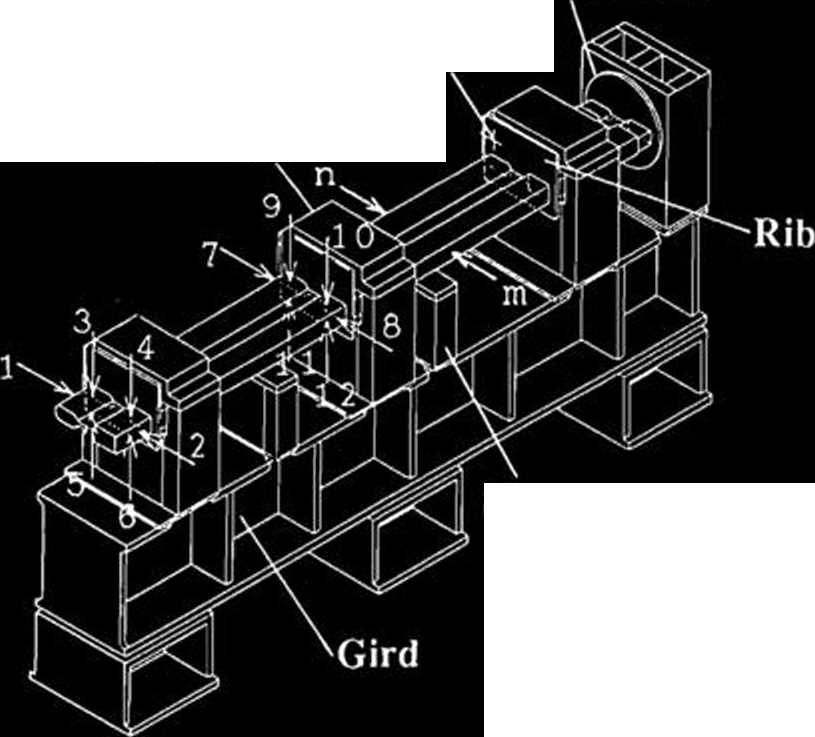
Fig. 1. Schematic diagram of the experimental model chamber with slide guides. The points of measurement are denoted by numbers.

Fitting cone r i b
|
l.D. |
O.D. |
o |
O | ||||
|
Designed |
value |
201$0,5 |
20 !1« |
501 ±10' |
50- ±10' | ||
|
Pin |
1 |
20.005 |
19.995 |
491 59' 55' |
501 00' 05' | ||
|
Heasured |
value |
Pin |
2 |
20.005 |
19.992 |
491 59' 58' |
50# 00' 05' |
|
Pin |
3 |
20.005 |
19.998 |
491 59' 50' |
491 59' 58' | ||
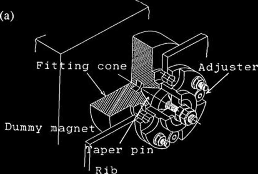
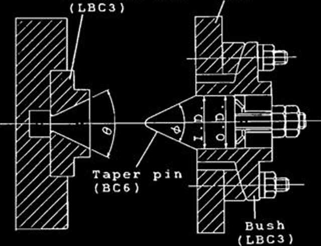
Fig. 2. Schematic diagram of the slide guide, (a), Mecha-nism of the slide guide; (b), Dimensions of fitting parts.
We manufactured a new chamber mount, namely a slide guide, and mounted a straight-section chamber with ribs for suppressing chamber deformation. An end of the chamber is fixed and allows no chamber motion in any direction before and after bakeout.
Fixed end Taper pin
An experimental model chamber with three slide guides and their structures are shown in Figs. 1. and 2, respectively. A solid lubricant of copper alloys is applied to taper pins (BC6) and fitting cones (LBC3). The chamber is positioned by a taper pin inserted tightly in a fitting cone at room temperaturę. During bakeout, the taper pin is released by thermal expansion of the chamber. Therefore the chamber motion is allowed in any direction during bakeout, but the chamber returns to the original positions of each bakę cycle. This chamber mount is capable of releas-ing a large force caused by the displacement of the chamber on heating.
The displacements of the chamber were mea-sured with 1 scalę dial gauges set in the transverse sections of the chamber.
The maximum temperaturę difference between points m and n in Fig. 1. during bakeout was 10 °C, which caused a 600 ^m-deformation at the end of the chamber. The taper pins were perfact-ly released during bakeout and fit on after bakeout. Figurę 3 (a) shows the displacements of the chamber. The displacements of the chamber and a gird were less than 42 ptm and 12 /im on each point of the measurements, respectively. Moreover the displacement of dummy magnets was negligibly smali, compared with other defor-mations. This means that the position of a beam position monitor (BPM) is ensured within an
Ishikawajima-Harima Heavy Industries Co., Ltd.
Wyszukiwarka
Podobne podstrony:
94 RIKEN Accel. Próg. Rep. 24 (1990)111-5-2. Design of a Decay Muon Channel Using an Axially Symmetr
102 RIKEN Accel Próg. Rep. 24 (1990)111-5-8. Performance of Isotopic Separation in RIPS T.Nakamura,
160 RIKEN Accel. Próg. Rep. 24 (1990)V-2-12. Measurement of a 508 MHz Model Coupler forthe SPring-8
RIKEN Accel. Próg. Rep. 24 (1990)V-2-30. Manufacture of a Complicated Ceramic Chamber and Its Joinin
29 RIKEN Accel. Próg. Rep. 24 (1990)111-1-19. Dissociation Cross Sections of nLiK. Soutome, S. Yamaj
92 RIKEN Accel. Próg. Rep. 24 (1990)111-5. Instrumentation1. Design of a Microbeamline for a Compact
103 RIKEN Accel. Próg. Rep. 24 (1990)111-5-9. Test Experiment of the GARIS/IGISOL K. Morita, T. Nomu
105 RIKEN Accel. Próg. Rep. 24 (1990)111-5-10. Velocity Distribution of IGISOL lon Beams M. Koizumi,
108 RIKEN Accel. Próg. Rep. 24 (1990)111-5-12. Status Report of the RIKEN Swinger-Magnetic Analyzer
110 RIKEN Accel. Próg. Rep. 24 (1990)111-5-14. Test for Dispersive-Mode Beam Transportto the SMART
116 RIKEN Accel. Próg. Rep. 24 (1990)111-5-19. Responses of Large Position-Sensitive Detectorsto Hea
121 RIKEN Accel. Próg. Rep. 24 (1990)IM-5-23. A Test for SMART Neutron Detectors H. Orihara, K. Hata
RIKEN Accel. Próg. Rep. 24 (1990)111-5-25. High Speed Serial Data Link for PC-9801 J. Fujita > PC
więcej podobnych podstron