372596202
199
RIKEN Accel. Próg. Rep. 24 (1990)
V-2-34. Bending Fabrication of a Vaccum Chamber
T. Nishodono, T. Bizen,* Y. Suzuki,* and S.H. Be
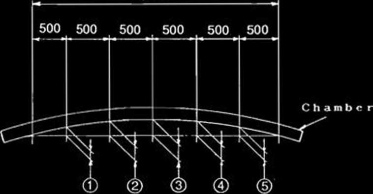
3000
|
Points of aeasureaent |
(D |
<D |
© |
© | |
|
22. 539 m |
♦ |
* |
* |
» |
• |
|
radius |
27.8 |
44.6 |
50.0 |
44.5 |
27.8 |
|
Chaaber 1 |
16.8 |
27.0 |
30.2 |
26.7 |
16.1 |
|
Chaaber 2 |
22.6 |
35.8 |
40.7 |
36.4 |
22.7 |
|
Chaaber 3 |
22 . 1 |
35.3 |
39.7 |
35.3 |
22.1 |
« calculated valu«?
A circulating electron beam in a storage ring reduces electromagnetic fields in vacuum system components such as chamber, bellows, and gate valve. When a straight chamber is used in a bending magnet section, the break of symmetri-cal electromagnetic fields might drive a trans-verse instability for an electron beam, because a curved beam causes an offset in respect to the center of the beam chambers transversally. Therefore chambers in the bending magnet section should be curved along beam orbits.
To ascertain the feasibility of bending the complicated chamber to be used in bending magnet section of the SPring-8 storage ring, we built a bending magnet chamber by means of stretch forming. Figurę 1 shows the schematics of a stretch former, and Fig. 2 the photograph of a bending test. In this test we used an existing forming błock of 23-m curvature radius for an another chamber to save the building cost of the bending magnet chamber.
Hydraulic strcch cylinder
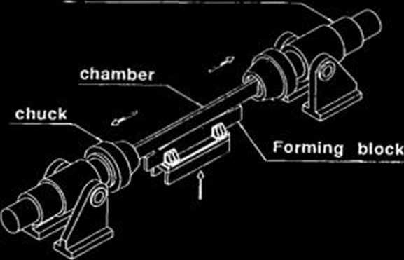
Fig. 1. Schematic diagram of a stretch former.
Fig. 3. Bending radius of the chamber after stretch forming.
I
I
|
r-4 |
H H N C |
* JUL | 5 2_aj |
iĄ co co | ||
|
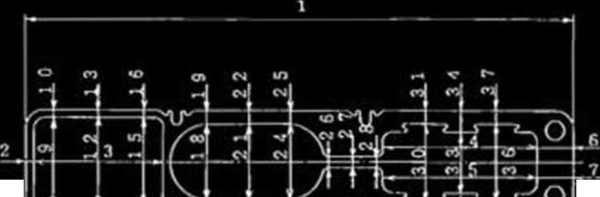
No |
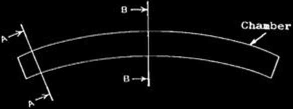
Section A |
No |
Soction A |
Section B | |
|
i |
-0.10 |
0.0 |
20 |
+0.01 |
0.0 |
|
2 |
+ 0.05 |
+ 0.14 |
21 |
-0.10 |
-0.40 |
|
3 |
-0.10 |
♦ 0.10 |
22 |
-0.02 |
-0.01 |
|
4 |
0.0 |
-0.20 |
23 |
+ 0.02 |
-0.02 |
|
5 |
-0.10 |
-0.10 |
24 |
-0.10 |
-0.50 |
|
6 |
-0.10 |
0.0 |
25 |
40.01 |
-0.04 |
|
7 |
+ 0.10 |
0.0 |
26 |
-0.20 |
-0.50 |
|
8 |
4-0.07 |
40.04 |
27 |
-0.30 |
-0.70 |
|
9 |
0.0 |
+0.60 |
28 |
-0.30 |
-0.60 |
|
10 |
♦ 0.06 |
+ 0.12 |
29 |
+ 0.08 |
-0.12 |
|
1 1 |
-0.03 |
40.03 |
30 |
-0.20 |
-0.60 |
|
12 |
0.0 |
0.0 |
31 |
4*0.02 |
+0.08 |
|
13 |
♦ 0.03 |
+ 0.05 |
32 |
♦ 0.03 |
-0.05 |
|
14 |
0.0 |
♦ 0.03 |
33 |
-0.10 |
-0.30 |
|
16 |
+ 0.10 |
0.0 |
34 |
-0.01 |
-0.02 |
|
16 |
0.0 |
+ 0.02 |
35 |
-0.09 |
-0.01 |
|
17 |
0.0 |
♦ 0.06 |
36 |
0.0 |
-0.20 |
|
18 |
0.0 |
-0.10 |
37 |
+0.02 |
-0.02 |
|
19 |
4-0 . Ob |
+0.06 | |||
Fig. 4. Deformations of the cross-sections of the chamber.
i
Fig. 2. Photograph of the test.
*
Ishikawajima-Harima Heavy Industries Co., Ltd.
Wyszukiwarka
Podobne podstrony:
92 RIKEN Accel. Próg. Rep. 24 (1990)111-5. Instrumentation1. Design of a Microbeamline for a Compact
103 RIKEN Accel. Próg. Rep. 24 (1990)111-5-9. Test Experiment of the GARIS/IGISOL K. Morita, T. Nomu
116 RIKEN Accel. Próg. Rep. 24 (1990)111-5-19. Responses of Large Position-Sensitive Detectorsto Hea
158 RIKEN Accel. Próg. Rep. 24 (1990)V-2-ll. Bump Magnet of SPring-8 H. Miyade, H. Takebe, and S. Mo
174 RIKEN Accel. Próg. Rep. 24 (1990)V-2-20. Performance Test of Lumped NEG PumpS.R. In,1 T. Maruyam
11 RIKEN Accel. Próg. Rep. 24 (1990)111-1-2. Three a Disintegration of 12C in the Field of208Pb Nucl
63 RIKEN Accel. Próg. Rep. 24 (1990)111-2-28. Development of Nuclear Track Microfilters N. Nakanishi
72 RIKEN Accel. Próg. Rep. 24 (1990)111*3-8. Dry Separation of Radioactive Nuclides from a Gold Targ
80 RIKEN Accel. Próg. Rep. 24 (1990)111-3-16. Development of an lon Beam Sputtering Method toPrepare
174 RIKEN Accel. Próg. Rep. 24 (1990)V-2-20. Performance Test of Lumped NEG PumpS.R. In,1 T. Maruyam
63 RIKEN Accel. Próg. Rep. 24 (1990)111-2-28. Development of Nuclear Track Microfilters N. Nakanishi
więcej podobnych podstron