Fr. Fassmer GmbH & Co. KG
Industriestr. 2
D - 27804 Berne
Tel. +49 (0)4406 / 942-0
Fax +49 (0)4406 / 942-100
Email: info@fassmer.de
Internet: www.fassmer.de
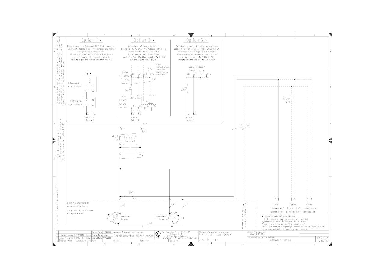
SCHALTPLAN FÜR BEREITSCHAFTSBOOTE
WIRING SCHEME FOR RESCUEBOATS
RR & FR(I)R WITH OUTBOARD ENGINE & E-START
Document: WN.0000-710.23.01.2
No. Modification
Date
Name
0
Ludwig
1
options added, converted to standard dwg
09.10.03
Reinke
2
cover sheet and document no. updated
17.09.06
Hellwege
Engine:
1 outboard engine, electric start
No. of batteries:
1 per engine
Battery charging:
Option 1: 1 solar module 12V/10W for each
battery
Option 2: 1 battery charger 42V AC → 12V DC
(incl. charging socket)
Option 3: 1 charging socket for shipside auto-
matic batt. charger (output 12V DC)
Execution: Standard
No switchboard. Searchlight, all-round light (op-
tional) and compass light (optional) perma-
nentely connected
Options included:
All items marked with „option“ are only fitted if
stated so in order part list and/or order specifi-
cation
Wyszukiwarka
Podobne podstrony:
BSA A10 wiring diagram id 93494 Nieznany (2)
ihcnjvcgga scheme
9 2 1 5 Packet Tracer ?signing and Implementing a VLSM?dressing Scheme Instruct
schemes Q5UYM5LOWA26TU2RNVNF6WXRWGHABBW3AVTHNUQ
Wiring for UK Telephone Sockets
9 2 1 3 Lab ?signing and Implementing a Subnetted IPv4?dressing Scheme
51 Bulkhead Wiring Harness (In Engine Room)
9 2 1 4 Lab ?signing and Implementing a VLSM?dressing Scheme
Colregs Rule 10 Traffic Separation Schemes
TV SCART Scheme
68 Wiring
aldolase digestion-scheme
22 appendix electrical wiring system
BYT 2004 Work organization methods and schemes
68 Wiring
ELECTRICAL WIRING ROUTING
How to Use the Electrical Wiring Diagram
Lab 6, 9.2.1.5 Packet Tracer - Designing and Implementing a VLSM Addressing Scheme Instruct
więcej podobnych podstron