
Krell KSA-50 Building Wiki
Index:
Ch 1: History of the thread
Ch 2: References and Corrections
Ch 3: How to build with examples
Ch 4: Krell Facts and Reviews
Ch 5: Upping the power!
Appendix- Krell-O-Tracker
Chapter 1: History of the Thread
Once upon a time…
Well it all started when user “bra” posted this
and said he would like to make a Krell KSA-50.
Threads from 2004: KSA 50 Board Research And Development.
- Our main man Jan then stepped up to the plate and said “I can make the PCB-layout”.
- Luke sorta requested the board be single sided and Jan in
agreed that it would be easier for
DIY’ers to make their own if it were.
- Jan publishes his schematic for thread review, quick work in my opinion.
- Pavel suggested and Jan agreed that the project remain a Krell Klone and not be an “improved
version”.
- Jan requests last minute updates before making the PCB layout.
- Rabstg has taken on a group buy for the boards designed by Jan, and posts preliminary information
on the boards.
Threads from 2005: Boards (More Boards) and Building.
A Krell
[Group Buy #1 (Jan's Boards) Wiki]
is created, edited, and eventually by 14 January 2005,
112 boards are ordered.
Jan, designer of the 1st PCB board set, posts the following remarks:
Amazing that this thread should reach more then 400 replies
There must be some interest for this project
Turns out to be quite the understatement.
The PCB Boards from the first group buy are shipped.
is posted in a separate thread March 3, 2005.
NUTTR has his Krell Clone working on March 5, 2005. Pics in
Mark A. Gulbrandsen posts a pic of his KSA 50 (not in chassis) with data indicating that his build
is working as of March 5, 2005. See also
Links to the original KSA 50/100 soft start circuit schematics.
Pics of Algar_emi's hardware for use in the Krell Clone.
Mark makes the following statement:
If you have studied many amplifiers like I have over the last 25 years you will find that the circuit really is nothing
very special and its very simple. And thats what I like. The result is one of the best sounding Krell amplifiers ever
designed and it is considered one of the top ten amps ever designed and still used by many reviewers today as
their refrence amp........ Thats also what I like.
No-one in this group is building the KSA50 because we think they are the best at any cost (I hope), most of us
aren't even fooling ourselves that they are the best for the costs we are incurring...
Basically we are building them for a lot reasons including but not wholly limited to...
They are cool,
Can be built easily,
have soul,
Sound 'good enough',
set a standard in their time,
won't involve litigation,
and are in their original form a minor work of art...
A pic of the Pinkmouse output stage.
Pictures of Wim's KSA 50 are posted March 24, 2005.
This "BUILD" Wiki page is created with a blank page.
K-Amps posts his "Class A Spreadsheet" in a Zip file.
Pinkmouse is designing a new board, schematic shown in this post. Board in
. People
immediately show an interest in ordering these boards.
[Post #1601]
Pinkmouse prototype board is shown. Hardware shown in followup postings.

Pinkmouse prototype board is shown. Hardware shown in followup postings.
Assesears shows a pic of his krell hardware being tested.
Pinkmouse shows oscilloscope square wave measurements of his prototype with different
capacitances on Q107/108 (C105 & C106). See also
and 1674.
Pinkmouse schematic for Pinkmouse board as tested and working, parts list in #1694.
"Final" Pinkmouse boards, see up to #1780.
Coloumb posts a pic of his chassis.
Stuart gets a new girlfriend (congrats!) but more importantly (for us) begins work on a very high
power version of the Krell clone.
NUTTR realizes that the Krell clone is heating up his room by quite a bit.
Stuart posts a pic of his basic output stage.
Stuart has a bunch of non-inductive output resistors and people start buying them from him.
Link to temp calculator on Analog Devices website.
KMJ posts the following observation:
Damn you guys can keep a conversation goin, I'm without internet for 2 days and already theres so much to read.
My mothers sewingcircle doesn't have a thing on you.
Mark posts a prototype of boards for the 2nd Group Buy.
Terry's amp is up and running. Looks nice.
LGreen's amp is up and running. Looks good.
Mark has shipped all the boards for the 2nd Group Buy.
neychi posts pictures of his Krell style chassis.
Mark G orders another 100 boards, for a third group buy of Krell KSA 50 clone PCBs.
Mark and Lyndon have successfully operated a new Krell clone, not yet in a chassis, using Mark's
boards.
Luke finishes his clone and puts up some pics. Hopefully a chassis is in the works.
Posts From 2006. Boards are Available and Amp Building Resumes.
Bra, who started this whole thing (3/27/04), has finally built a Krell clone (3/18/06). Two years and
6000+ posts, go figure.
Posts From 2007. Building continues...
Once again, a discussion of fans and how to keep things quiet.
Chapter 2: References and Corrections
Shortcuts and References
1. Jan's Board-- the 1st Group Buy
Jan’s web page for the Krell Klone :
http://www.delta-audio.com/Krell-Clone.htm
[Corrections to the Board (pdf)]
2. Pinkmouse Board-- the 2nd Group Buy
Important: For those using the Pinkmouse PCBs, some transistors used in the Pinkmouse PCB have a
different pin-out than those used in Jan's boards. Use the devices listed in Pinkmouse BOM.
3. Issues with parts
issues with wattage of zener diodes
Build Options and Issues
Protection Circuitry
- To build this amplifier without the voltage-current limiting protection circuitry (like the original), omit the following
components-
D301, D302
Q301, Q302
D303, D304, D305, D306
C301, C302
R301, R302
RVI1, RVI2, RVI3, etc...
Note- the parts list omits values for D305 and D306.
It is assumed that these are the same as D303 and D304.
I'm not sure this is correct, can someone verify this and then delete this line?
R124
Issues regarding R124. The value of R124 is not shown on the schematic.
R124 should be 4.7k, as seen in original schematics and verified through independant calcs and measurements
C105 and C106
The schematic lists the values of C105 and C106 as 390 pF. Good results were obtained with 47 pF.
See this link:
See this link:
Suggests using 33, 47, or 68 pF. Not 330 pF. And not 22 and 33 pF (post 1020).
It appears that there might be a slight difference of opinion on this.
Normal/low bias Construction Options
The board has options for normal (R126) and low bias (R144).
It is not shown is how to switch between these or how they are connected.
My guess-- A switch can be connected to short/open circuit the low/high bias pads, so, when the switch is flipped,

My guess-- A switch can be connected to short/open circuit the low/high bias pads, so, when the switch is flipped,
the pads are shorted making R126 parallel to R144. This gives a lower resistance and increases bias. As such the
board is mislabeled. This setup will have R126 as stand-alone for low bias, and the combination of R144 and R126
in parallel is high bias. Thus, first set R126 for low bias, and leave it alone; then flip to high bias and set R144 for
the desired high bias current. Because the low bias resistor is 5K, the parallel resistor I chose for R144 is 25K, so
that there is a wider range of tuning rather than having 5K in parallel with 5K (which gives a max setting of only
2.5K). This setup is shown in
. It was suggested less than 5K would be ok to put in parallel but 25K
has been tested and works.
See also
.
Power supply info: Transformers, Capacitors etc
The original KSA-50 (and KSA100) were both true dual mono amplifiers all the way back to the line cord.
In the original Krell it was ~37.5 VDC, bias ~1.9A per channel, ~60w/8ohm class A, ~75w/8ohm class AB
People have built these unmodified with 39VDC
Transformers:
Krell used a 400va transformer per channel, ie two per stereo chassis. In the course of production they used both
toroids and EI transformers so no big deal there.
A normal KSA50 channel has ~37v rails. This requires 2 secondaries at ~26v AC, or 52v center tapped. A minimal
transformer for two channels would be about 400va, you'd want more for driving low impedance loads.
Capacitors:
Each transformer was rectified then smoothed by a pair of 40000uF caps, so 2 x 40000 caps per channel, 4 per
stereo chassis. A fine alternative: the 68000/50v 'computer grade' parts that seem quite readily and inexpensively
available, check with Steve at apexjr.
Resistor Wattage Rating
The design specifies .5 watt resistors. It has been stated that most resistors can be 1/4 watt (from
):
Actually my KSA-50s all have 1/4 watt resistors except for the ones in series with the zeners, the ones at the pre-
drivers, and the drivers emitter resistors themselves. Those 4 are are 1/2 watt and the drivers get 2 watt. I get my
Metal films surplus for 5 cents each so 1/4 watt will suffuce at that price. Its also ok at 37 volt rails according to
Stuart Easson.
Emitter Resistors
The schematic indicates .5 ohm emitter resistors, RE1, RE2, RE3. These should be rated for at least 5w, in the
event very low impedance loads are driven a larger fraction of the considerable output power will be dissipated in
these resistors...
Other values may be used and affect the amount of class A bias and ultimate power delivery.
Actually the 'normal' range of values of the emitter resistors (0.22-1ohm) doesnt really affect the 8ohm power
much. For >2ohm loads I'd go with 0.5ohm or greater for better bias stability. If driving <2ohm loads to full power
the resistors will need to be seriously high power, and here lower values will minimize losses...
With the original power supply of 37.5 VDC and .5 ohm resistors, the result will be ~55 watts of Class A power, and
~75 watts of class AB power into 8 ohms.
HEAT SINKING
Plenty of heatsinking should be provided for this amp. Since this is a true class A design its going to dissipate right
around 150 watts of heat per channel when biased for 50 watts class A power level. Air tunnels are reccomended
for this and can be easily accomplished by placing two flat back sinks face to face and installing a pair of 4" fans
below them. Arrange the fans so they blow up and out the top of the tunnel. The fans can be run at half speed or
less but don't allow sink temperature to get over 60 C. or device reliability may be short. A temperature servo could
also be an efffective addition keeping fans at just enough speed to keep the sinks at about 55 C. or lower.
The use of a 60 deg.c to 65 deg.c Clixon thermostatic switch mounted to each heat sink and wired back to the
transformer primary is recomended as a safety precaution to shut down the amp and to save the output devices in
case of excessively high temperature or should a cooling fan fail or stall. These switches are inexpensive insurance,
or be sure your home owners policy is up to date! As an alternative each Clixon Switch could be wired to drastically
lower the bias of the overheating channel when it is activated by too high of temperature.
A graph of temperatures of such a fan cooled heatsink over 3 hours of elapsed time is posted at
. The
4 graphs are are for a fan cooled output stage (2 channels), a convection cooled driver stage (1 channel), and a
convection cooled voltage regulator (for driving the fans, softstart etc...).
Suitable convection heatsinks will need to be extremely large. See
for how to compute the thermal
resistance of a heatsink that can dissipate the heat sufficiently.
User 'geezer1944' in
has provided a
to a website with additional heat sink calcualtions.
Mounting the driver devices and the bias sense device an inch or so apart on the main sink for each channel will aid
in keeping the driver devices at a reasonable operating temperature. In fact if done this way they should not exceed
the operating temp. of the amp. This method also provides excellent thermal tracking. This was one of the main
reasons for Pink Mouse's board re-design... to easily allow booth drivers and the bias device to be mounted on the
main heat sink.

However, it was stated in
that the driver Transistors need not be on the output heatsink for thermal
tracking, but the bias transistor should be mounted in some way to track the output device heat:
The Vbe multiplier, q111 has to track the temp of the outputs. The drivers are not required to track any particular
temp, they just have to be kept at a safe temp.
As q111 gets hotter the bias voltage will decrease in proportion to the temp. As the drivers and outputs get hot, the
bias current increases in proportion to the temp. In a perfect world the reduction in voltage keeps the bias current
pretty much the same...
The drivers dissipate power at a fairly constant fraction of the output stage proper (~1/40). So if you choose a
separate sink for them and attach q111 to it, I think you achieve a good approximation of the necessary thermal
tracking, but the size of sink you choose needs to keep the temp of the drivers and q111 in the same ballpark as
your outputs.
Wire Thickness
Don't know what thickness wire to use?
Wire thickness can be computed using the link provided in
. Here is the
Driving the Output to Clipping.
To calculate at what voltage the input will cause the output to clip, see
, which states:
output voltage depends on your +-Vrail and gain.
Assuming you have +-38Vdc and the losses from rail to max output voltage are 4v then you have 34Vpk to drive
your load.
Divide by sqrt 2 = 1.4142 to give rms output = 24.04Vac (72w into 8R)
The gain of amp = r130/r129 + 1 = 22/1.5 + 1 = 15.67
Input required to produce 24.04V = 24.04/15.67 = 1535mV
From this you can insert any gain resistor values and max output voltage to determine the maximum input voltage.
Ground Loop problems?
I had a problem with a ground loop at the inputs. Whenever both inputs were connected there was a 60 cycle hum
present. I tried many different things until pooge posted this in
. I followed those instructions and now
the amp is dead quiet.
Chapter 3: How To Build With Examples
The following comments are hints from people who have built up one of these boards.
Soft Start Circuit
Many have suggested that a "soft start" type of circuit will be necessary to avoid a large surge upon power on.
There are a number of threads that relate to soft start circuits.
A circuit based in Rod Elliot's Project 39, Figure 2 (finally working in the later posts, final version
Also See
How to wire a soft start with the power supply.
A recent article on inrush limiting.
Indicates that Algar Emi has a soft start circuit up for a group buy on this
.
Comment- The use of a CL-60 thermisitor (such as Digikey part no. KC006L-ND) in-line with the big transformer
primary works fine for inrush limiting. Use one per channel assuming dual mono. This is the same thermisistor used
in the Pass amps. The thermister will get hot during operation so leave room for and account for this. Also, because
the thermistor will be hot during operation, this technique offers no protection to a on...(long time)...off...(short
time)...on cycle because it needs time to cool in order to get its resistance back up.
If no method is inrush limiting is utilized one will definately blow the bridge rectifier!
Testing The Driver Board
You don't need outputs to test the board. The drivers are loaded by their emitter resistors which need to be
present...the bias should be set to give about 1.2v across each of the resistors.
The gain of the amp is set by r130 divided by r129, or about 14.6. So you will need a little over 2v to get it to full
output. The KSA100 had higher gain in proportion to it's higher output voltage potential.
If your front end is working like mine you will get the following voltages:
r103, r107 (rail-0.6v)
r108, r109 (rail-27v)
r112, r113, r116, r117 ~2.2v
r120, r121 ~1.59v
r122, r123 ~1v
(voltages measured across the identified resistor)
Obviously the junction of the driver emitter resistors should be somewhat close to 0v, but may need some trimming
with r105
with r105
Resistor tolerances can make all of these vary some, but probably not more than +-25%, or at least if component
tolerances are far enough out to make the voltages vary more, consider selecting other components...
Output Transistor Choice
in
The specific choice of transistors for the output is not without some controversy. Here's my synopsis of the threads
'findings':
mj15003/4: The original amp used a pair each of these, per channel. Very rugged, but sort of slow, technically
there are now better transistors. Not available in the plastic packages, so you need to be good at drilling or have
pre-drilled heatsinks. With transformers in the 300-400va per channel 2x of each are more or less bulletproof.
Bigger transformers would suggest more paralleled transistors, since the rails won't collapse as low impedance loads
are driven and the transistors would be at risk...
mj21193/4: The closest 'modern' transistor to the originals, much better gain linearity, more package options,
easier to use. In the TO3 form can be substituted pretty much 1-1, in plastic package the ratio is probably better
kept at 2-3. Since they are not much faster than the originals instability is not likely any more of a problem.
mj4302/4381: Very much faster, technically a much better transistor, AFAIK not available in TO3, so more are
needed for an equally bulletproof output stage, 3 pairs per channel for instance. These transistors are very much
faster than the originals and I'd exercise care in the output stage wiring, better to be safe than sorry.
The other transistors you mention (2SA1943 /2SC5200) are more or less unavailable, but there are a lot of fakes
on the market, so the consensus seems to be avoid them and use the modern equivalents.
I have tried the mj15003/4 and the 21193/4 and they both sound excellent to me...I think the amp is probably
'better' into low impedance loads with the 21193/4 because of the better gain at high currents loads the drivers less,
and it's easy to use more of the plastic outputs.
Transistor DC Measurements
Mark measured the DC components of his board in
. They are with reference to ground and keep in
mind the rail voltage is +/- 39 volts DC
Q-101
E .745
B 142.9 mv C +36.07
Q-102
E .442
B 143 mv
C - 35.6
Q-103
E .617
B 0
C +35.9
Q-104
E .320
B 0
C -35.75
Q-105
E +36.5
B 35.95
C 0
Q-106
E -36.32 B -35.7
C 0
Q-107
E +37.05 B +36.5
C +1.29
Q-108
E -36.8
B -36.33
C -1.288
Q-109
E +.728
B +1.296
C +38
Q-110
E -.733
B -1.296
C -37.88
Q-111
E -1.06
B -.563
C +1.296
+ side OP device E 120 mv B +.728
C +38.09
- Side OP Device E 140 mv B -.733
C -37.89
Setting the bias
From Post #2508.
Setting the bias is easy...turn the pot so the DC you measure across both the driver emitter resistors is at a
minimum. Connect the driver board to the outputs, then if you can, slowly apply power to the whole shooting
match, monitoring current draw, anything more than a few 10's of milliamps is bad, you'd want to turn everything
off and check your wiring......If you can't do it slowly, then just turn it on...from a distance?
Anyway once you have all the parts connected, power applied and no smoke issuing from anything, attach a meter
to measure the voltage across one of the 0r68 output emitter resistors (say Re1), and another to measure the
output voltage relative to ground, and if you have 3 meters (and who doesn't?) attach another one to measure the
total voltage across the driver emitter resistors r127/128...
Slowly turn the bias pot to increase the output idle current, you can also measure this as the voltage across the
25ohm driver emitter resistors, nothing happens at first, basically until the board output voltage reaches about 1.2v
across r127 & 128, then the outputs start to turn on and you will read a voltage across Re1...keep increasing until
you have about 0.2 volts across Re1...with 3 output pairs this corresponds to ~1A total idle current, you'd probably
want to allow this to sit for a little while check temps, make sure the voltages across all the output emitter
resistors are nearly the same, any big discrepancy should be investigated. Once you are satisfied that everything is
OK, start increasing the bias until you see ~0.4v on Re1...as the temperatures on the sinks change this is going to
move around, once it seems to have settled, adjust the other pot to reduce the DC offset to the lowest possible
value (<50mv was easy to achive on all the boards I've made). This will wander as the temps change, so repeat
the process a few times over the course of an hour or two...
(NOTE- .4v across Re1 is only valid with .68 emitter resistors, do not attempt this with lower value resistors--

(NOTE- .4v across Re1 is only valid with .68 emitter resistors, do not attempt this with lower value resistors--
compute the class A power you will get separately. With 4 output device pairs and .499 ohm emitter resistors 50 W
class A into 8 ohms is about .22 V across the emitter resistors, into 4 its about .32V).
The bias resistors (R144, R126) are setup such that:
Lower R = Higher Bias/ Higher R = Lower bias.
See
If you are not sure about the bias and need to begin at the low bias point and are not sure which way to turn the
trimpot to reduce bias, here is a foolproof trick that has helped me over the years.
Disconnect the driver's emitter to the output's base (saving the outputs from being driven). Then measure the
voltage across the B and E of the driver, less than 0.6vdc and you are ok to go ahead with initial biasing, (This is
class AB territory) above 0.6vdc and you are in high bias/ Class-A territory and you need to lower the bias to 0.5
before you connect the driver to the output stage. This method is a quick test of verification and not extremey
accurate but very practical if you are not sure which way the trimpot should be.
Class-AB amps need to have about 0.50 to 0.55 vdc across the BE of the output devices as a quick test.
Another quick test I do it use a 100-200 watts lamp in series with the amplifier, then turn the amp on and set the
trimpots such that the lamp goes down to a dull amber... this is low bias setting. Then remove the lamp and set the
bias correctly using the voltage readings off the OP device's emmitter resistors as others have explained.
Setting your particular bias to a certain number of Class A watts is described in
Chapter 4: Krell Facts and Reviews
According to Krell's web site, the KSA-50 was in production from 1981 through 1987.
Here is a web site showing pics of Krell amps:
Link to
[Macleans Krell KSA-50 cleaning/refurb page]
Link to
[(Original) KSA 50 Photo Album]
Link to
Chapter 5: Upping the Power
There are requests for this board to be used with higher rails. In the order of +/-100vdc, or 500 watts RMS into 8
ohms. Stuart Easson is working on the prototype. He has designed a CCS for the input differential allowing the
amplifier to be run from 20 to 120 volts. He has so far successfully tested the prototype into 4 ohms but needs a
larger power supply.:
Also if you need more power there is the KSA-100 clone project, whose wiki can be found
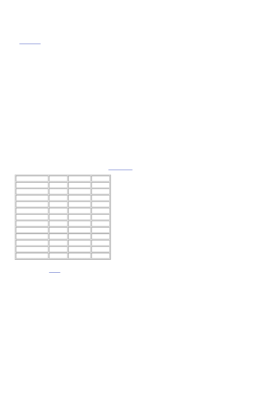
Appendix - Krell-O-Tracker
This is to keep track of variations on this project, and give others guidance on what was used. If you have one in-
progress, feel free to enter the info on the parts you are using or plan on using. Feel free to enter notes, links, pics,
comments and such in the last col.
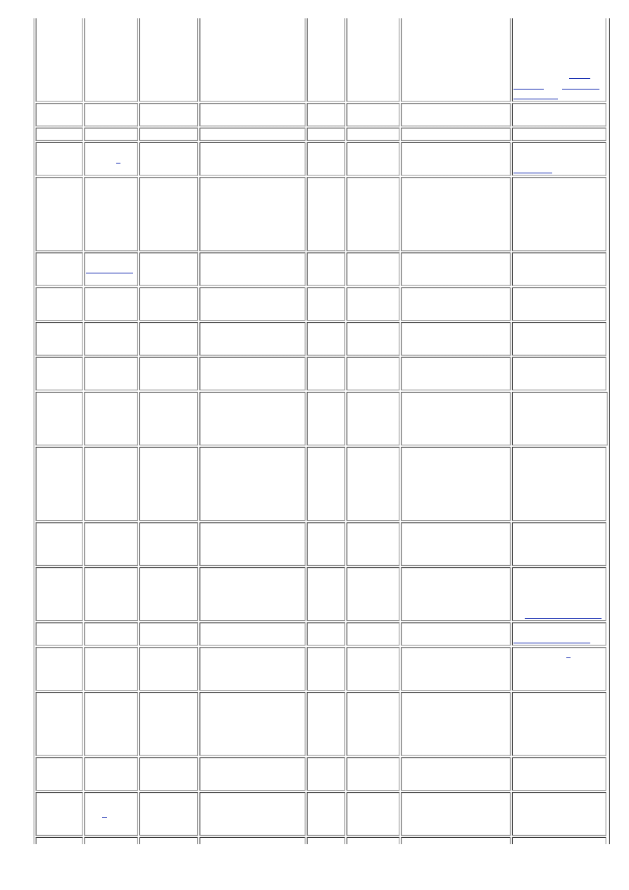
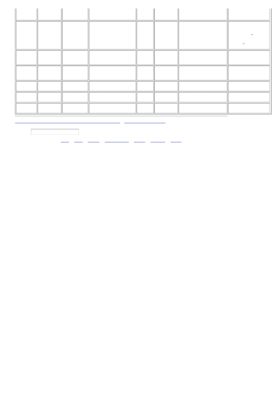
Date
Finished
or IP
Name
Transformer Total uF Per Ch.
DC
Rails
Emitter
Resistors
Output Devices & #
Per Ch.
Notes, Links, Pics,
Comments
1981-87
Original
400VA x 2
80,000 uF
37.5
VDC
0.5 Ohms
MJ15003/4 (2 each) TO-3 50 WPC Class A
1.
Mark G.#1
680VA X 2
112,000 uf
39.0
VDC
.68 ohms
MJL 21193/4 (3 each)TO-
247
54 WPC Class A -
Amp has been
scrapped out to build
permanent version.
2.
Assesears
500VA x 2
90,000uf
33.0VDC 0.68ohms
MJL4281A/4302A(3
each)TO-247
36WPC ClassA
(small
heatsink)
3.
Stuart
Easson
2.8kVA x 2
2x25000
105VDC 0.68ohms
MJ21193/4(16 each)TO3
50W/Class A
500W/Class B
4.
Stuart
Easson
450VA x 2
CLC 68k/2.7m/68k
37v DC
0.68ohms
MJ15003/4(2 each)TO3
50W/Class A
75wClass B
5. July 31,
2005
still4given
500vA X 1
CRCRC 45,000
42 VDC 0.68 ohms
MJ15003/4 (3 each) TO-3
(don't know)
Notes- low/high bias
option switches from
6. August
8, 2005
LGreen
700VA x 2
128,000 uF
37 VDC .499 ohms
MJ21193/4 (4 each) TO-3
option switches from
20 WPC Class A to 50
WPC Class A at 8
ohms, fan cooled; 70
lbs/ 32Kg. Discussion
and Pics- (a)
7. in
progress
Mark G. #2 ---
112000 mfd
---
0.68 ohms
MJL 21193/4 (3 each)
Proto test of WIKI
boards
8.
NUTTTR
800VAx3
272,000uf/ch
38v DC
0.68ohm
MJ21193/4 (5 pairs/ch)
Not yet...
9. March
2006
JoeyDD
500VA x 2
80000uF/ch
36VDC
0.68ohm
MJL21193/4 (3 pairs/ch)
2 monoblocks,
passive cooling,
10.
jacco
vermeulen
300VAx8
CLC,78000uFx6,2.5mHx2
aircoils/ch
35VDC
0.68Ohms
2SA1216/2SC2922(12/ch)
4 discrete voltage
regulators for main
and driver board with
9VAC/27VA step-up
toroidals/ch,80x80mm
Papst fansx6/ch,7
amps bias?
11.
November
26, 2005
500VA X 2
112,000 Per Chan.
+/- 40
F. .68
6 Ea MJL21193/4 Chan.
DC Variable Speed 15
vdc Fans Running at
6.5 V.
12.
November
28, 2005
Luke
25V@7.5A
CRC 96,000uF
36 VDC 0.4 ohms
MJL4281, MJL4302 (3
each) TO-3
(don't know)
13. A
week or
so left
KMJ
2x540VA
132k uF / Ch
38VDC
F. Re
MJ15003/4 (3 each) TO-3
Fancontrolled cooling
and monitoring done
14.
February
27,2006
Mark A.
Gulbrandsen
2 kva dual
secondaries
56,000 per rail
+/- 38
volts
MJ21193/94 3 each TO-3
Dual fans at half
speed. Final version
for me
15. In-
Progress
Googler
2KVA Bel
Canto Dual
Pri/Sec
searching
+/-
40VDC
?
6 x MJL21193/4 -chnl
Heatsinks are
12Lx5Wx5H w/ 14
ribbed fins. Boards
Stuffed!! Need PSU
CAPS
16. In
progress
niles
2x500VA
56,000 per rail
~41V
DC
0.68R
3 Ea MJ21195/6 per
Chan.
Building matched pair
as bridged
monoblocks using
authentic Pass A2
sinks with custom
machined chassis
fittings
17.
Collecting
parts
bikehorn
1x 1250 VA
xformer with
2x 39-0-39
sec'ys
ESP capacitance
multiplier
39 VDC 0.5 ohm
MJL21193/4 TO-3P, 5
pairs/ch
will include VU meters
18. June
27, 2006
zlast
2KVA 28X2
120000 uf Rail
+/-40 V 0.47 ohm
3 pair MJL21193/94 per
channel
4 channels/
redesigned boards so
outputs transistor on
board /50WPC Class
A.
19. July 3,
2006
Farl
1X500 VA
66,000 uf per rail
+/-41V
.68R
3 pairs MJL21193/94
Maybe 50W Class A
20. in
progress
Andrew T.
30+30Vac
750VA
60mF per rail
+-
42Vdc
Re=0r333
6pr 2sa1943/c5200
passive cooling 3off
8"*8"*2" sinks/ch
100W ClassA
into 6r,
Iq=3A, twin drivers
2sb649/d669, +-
42Vreg frontend
21. In
progress
Harry3
Two 500VA
25+25Vac
56000uF per rail plus
1000uF & 0.1uF caps
next to O/P transistors
+-
35Vdc
0R5
6pr 2SA1943/2SC5200
2x80VA trans. for
front end-will
regulate. Two
Semikron heatsinks
300x200mm - 80mm
fins plus 2 fans
22. In
Progress
Harry3
Two 500VA?
30+30Vac
60000uf per rail plus
1000uF & 0.1uF caps
next to O/P transistors
+-
42Vdc
0R68
6pr 2SA1943/2SC5200
Two 12Volt fans
running at 7 Volts,
very low noise.
23. In
Progress
1.6KVA 28x2 68000 uf/rail
+/-40 V .68R
3 pair mjl21193/4
2 stereo amps 4
passive heatsinks
15.5"L 5.5"W 6"H 46
fins ea.
24.
24.
September
17. 2007
Steenoe
2 pcs 500VA
26x2
90.000uF per channel
E. 35V
0,68r 6W
MJW1302A/MJW3281A 3
pairs per channel
Passive cooling,
weight 42 Kg
25. Jan 01
2008 / IP
B. Jack
Richards
C. 2 X 500VA D. 44000uF/chan/rail
E. 38 V
F. Re=0.5
G. # 4xMJ21194
H. Bought fake trans
from ebay
(HonestCard
) ended
up buying from
OnSemi
. Now sounds
fantastic
26.
February,
2008
john65b
1240VA
2 x 56,000uf/rail uF
37 VDC
Re R68
biased @
.65mv
3pr 2SA1943/2SC5200
Sounds EXCELLENT.
Bests my UCD400 by
quite a bit
27.
December
22. 2008
neychi
2 x 400VA
2 x 47000uF per channel 38 VDC Re 0.5R
3 pairs MJL21193/21194
Passive cooling, 55W
class A
28. Date/
IP
B. Name
C. XFMR
D. uF
E. DC V F. Re
G. # Dev/Pack
H. Notes, links,etc...
29. Date/
IP
B. Name
C. XFMR
D. uF
E. DC V F. Re
G. # Dev/Pack
H. Notes, links,etc...
30. Date/
IP
B. Name
C. XFMR
D. uF
E. DC V F. Re
G. # Dev/Pack
H. Notes, links,etc...
Click here now to edit this WikiPage
Document last modified Mon, 01 Dec 2008 18:01:05
Search:
.
.
Copyright ©1999-2009 diyAudio.com
Wyszukiwarka
Podobne podstrony:
Design Guide 03 Serviceability Design Considerations for Low Rise Buildings
SIM Card Clone Guide
Girls’ guide to building a million dollar business Susan Wilson Solovic
Design Guide 05 Design of Low and Medium Rise Steel Buildings
A Guide to Building Outdoor Stairs budujemy schody na zewnatrz
guide camino aragones pl
Herbs for Sports Performance, Energy and Recovery Guide to Optimal Sports Nutrition
Meezan Banks Guide to Islamic Banking
Building a Greenhouse
NLP for Beginners An Idiot Proof Guide to Neuro Linguistic Programming
freespan spec guide
Eaton VP 33 76 Ball Guide Unit Drawing
Herbs to Relieve Headaches Keats Good Herb Guide
50 Common Birds An Illistrated Guide to 50 of the Most Common North American Birds
Configuration Guide WAN Access(V100R006C00 02)
installation guide
więcej podobnych podstron