CUSTOMER SERVICE
877.370.3604 (toll free)
INSTALLATION QUESTIONS
techsupport@kuryakyn.com
or call 715.247.2983
LIMITED WARRANTY
Küryakyn warrants that any Küryakyn products sold
hereunder, shall be free of defects in materials and
workmanship for a period of one (1) year from the
date of purchase by the consumer excepting the fol-
lowing provisions:
•
Küryakyn shall have no obligation in the event
the customer is unable to provide a receipt showing
the date the customer purchased the product(s).
•
The product must be properly installed,
maintained and operated under normal conditions.
•
Küryakyn makes no warranty, expressed or
implied, with respect to any gold plated products.
•
Küryakyn shall not be liable for any consequential
and incidental damages, including labor and
paint, resulting from failure of a Küryakyn product,
failure to deliver, delay in delivery, delivery in noncon-
forming condition, or for any breech of contract or
duty between Küryakyn and a customer.
•
Küryakyn products are often intended for use
in specific applications. Küryakyn makes no
warranty if a Küryakyn product is used in
applications other than intended.
•
Küryakyn electrical products are warranted for one
(1) year from the date of purchase by the consumer.
Components of Küryakyn products containing L.E.D.s
will be warranted for defects in materials and
workmanship for 3 years from the date of purchase.
•
Küryakyn makes no warranty of any kind in regard
to other manufacturer’s products distributed by
Küryakyn. Küryakyn will pass on all warranties made
by the manufacturer and where possible, will expedite
the claim on behalf of the customer,
but ultimately, responsibility for disposition of the
warranty claim lies with the manufacturer.
ABOUT OUR CATALOG
You’ll find all our innovations for H-D, GL and
Metric Cruisers in our annual catalogs. Order online
today–select the ”CATALOGS” icon. Each Küryakyn®
product comes with a Proof-of-Purchase good for a
complimentary catalog. Details in packaging.
Be sure to ask your local dealer about other
Küryakyn products, the motorcycle parts and ac-
cessories designed for riders by riders.
©2005 Küryakyn USA
®
All Rights reserved.
I N S TA L L AT I O N
Parts Included
1
Accessory Switch Housing
1
Wiring Harness with Switches
1
Hardware Kit, including:
2
M4 x 0.7 x 10mm FSCS Fastener
10
4” Nylon Cable Ties, Black
1
Dielectric Grease
1
Installation Instructions
Please read and understand entire instructions before starting installation.
thank you for choosIng küryakyn!
Please note
It is the installers’ responsibility to make sure all fasteners (including pre-assembled) are
tightened before operation of motorcycle. Küryakyn will not warranty components that are
lost due to improper installation. Periodic maintenance may be required.
tools suggested
Phillips screwdriver, Allen wrenches.
ATTENTION!
A factory service manual may be helpful in performing this installation. Do not
attempt to perform this installation if you are not confident in your ability to complete all
steps in the procedure; consult a trained technician.
ATTENTION!
When routing the wiring, be sure to keep the wiring away from any moving
parts. Küryakyn WILL NOT warranty any electrical component that fails due to pinched,
crimped, broken, abraded, or frayed wires.
CAUTION!
Protect any painted or plastic surfaces from possible contact with brake fluid;
brake fluid is corrosive and could damage these surfaces. Küryakyn is not responsible for
damage to surfaces caused by negligent or incorrect installation procedures.
Procedure
note:
The following illustrations show installation on a Honda GL1800; the procedure
for other bikes is similar. Standard installation is over the brake fluid reservoir, however the
switch housing can be also be mounted over a hydraulic clutch reservoir, if your bike is so
equipped.
-cont.-
f o r m a s t e r c y l I n d e r c ov e r
fIts honda: all gl1500 and 1800, all vtX1800 and 1300, ‘96–uP vlX600,
‘01–uP 750 sPIrIt, ‘02–‘04 750 ace deluXe, ‘04–uP 750 aero, ‘96–‘04 magna,
‘97–‘99 1100 ace tourer, ‘98–uP 1100 sPIrIt, ‘99 1100 aero, ‘02–uP 1100 sabre,
‘97–‘04 valkyrIe (eX. rune).
fIts yamaha: ‘96–‘01 royal star, ‘02 royal star venture, ‘99–uP road star
1600/1700, ’02–uP road star WarrIor.
7803-11MC-0906
a c c e s s o ry s W I t c h e s
7 8 0 3
InstallatIon
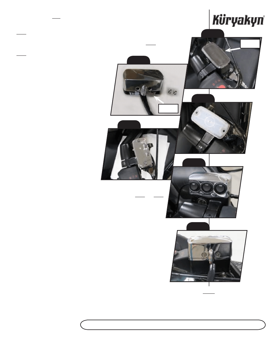
steP 1
Place a towel or other protective barrier over any painted or plastic surfaces. Remove the stock
reservoir cover, see PIC.1.
steP 2
Remove the two fasteners from the back of the switch housing. Remove the bottom plate, see
PIC.2.
steP 3
Carefully wipe any brake fluid from the diaphragm cover, see PIC.3. Install the
bottom plate of the switch housing over the reservoir and secure with the stock fasteners, see
PIC.4.
steP 4
Wipe away any brake fluid that may
have seeped between the reservoir and the cover,
or from around the fastener heads. Run the bike
and test the brake function for proper operation
and check for excess brake fluid seeping from the
reservoir.
STOP!
IF THERE IS ExCESS FLUID SEEPING
FROM THE COvER THIS MAY INDICATE THAT
THE COvER WAS IMPROPERLY INSTALLED,
DEBRIS IS TRAPPED IN THE FASTENER THREADS,
OR THAT THE DIAPHRAGM WAS PINCHED.
REMOvE THE COvER AND CHECK BEFORE
CONTINUING.
steP 5
A small amount of brake fluid may
have been present between the cover and the
diaphragm and will have now seeped from
around the fasteners or cover. Wipe this fluid
away and then run the bike and test the brake
function before continuing. Again, check for
excess brake fluid seeping from the reservoir.
steP 6
If you do not detect any seeping fluid, install the switch housing over the
reservoir; angle the front of the switch housing over the mounting pegs and push
the rear of the switch housing into place on the bottom plate. See PIC.5 and PIC.6.
Be sure not to pinch the wires at the back of the switch housing. Secure the switch
housing with the two fasteners removed in STEP 2.
steP 7
Route the wiring harness from the switch housing down the handlebar
and toward the frame of the bike. Follow the existing stock wiring. Be sure the
wiring does not interfere with the proper operation of any moving parts. Also, be
sure there is enough slack in the wiring to allow the handlebars to turn fully without
putting any excess stress on the wires. Secure the wiring with the supplied cable ties.
ATTENTION!
When routing the wiring, be sure to keep the wiring away from any
moving parts. Küryakyn WILL NOT warranty any electrical component that fails due
to pinched, crimped, broken, abraded, or frayed wires.
steP 8
Continue routing the red and black wires toward the bike battery
compartment. Keep the wiring away from any moving parts and be sure to secure
the wiring using the supplied cable ties. Be sure the fuse is easily accessible for
maintenance and/or emergencies.
ATTENTION!
Refer to you factory service manual for specific battery location and access. You may
need to remove components to route the wires safely.
-cont.-
a c c e s s o ry s W I t c h e s
InstallatIon
Page
2
PIc.3
PIc.5
PIc.4
PIc.6
PIc.1
remove
cover
PIc.2
remove
bottom
InstallatIon
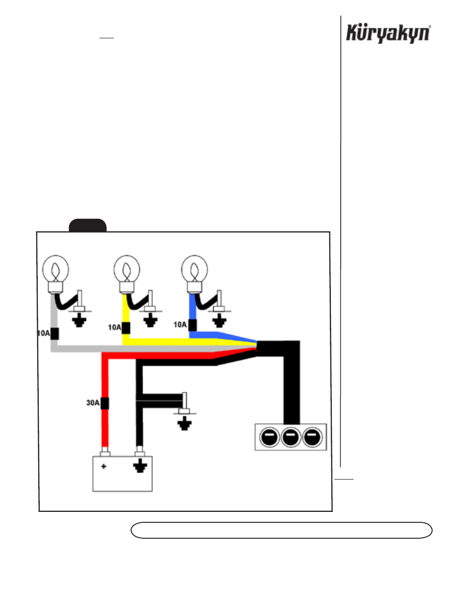
steP 9
Connect the red wire to the stock power connection. Connect the black wire to the bike
chassis or designated ground point. These wires provide power and ground to the lights on the
switch housing. See FIG.1 for a wiring diagram.
steP 10
Route the white, blue, and yellow wires toward your accessory lighting wires; be sure to
secure the wiring away from any moving parts using the supplied cable ties.
ATTENTION!
If you do not connect all of the accessory switches be sure to insulate the bare wires
with electrical tape or heat shrink to avoid shorting the switch.
steP 11
STEP 11.
Connect your accessory lighting power wires to the white, blue, and
yellow wires; you may lengthen or shorten the wires as needed. Connect your accessory lighting
ground wires to the negative terminal of the battery or the designated chassis ground. See FIG. 1 for
a wiring diagram.
ATTENTION! EACH ACCESSORY SWITCH IS FUSED FOR A MAxIMUM LOAD OF 10 AMPS; DO
NOT ExCEED THE MAxIMUM LOAD.
steP 12
Test the switch functions to verify the accessory lighting operates correctly.
Ride On!
InstallatIon
a c c e s s o ry s W I t c h e s
Page
3
fIg.1
Wyszukiwarka
Podobne podstrony:
Instrukcja montażu sufitów podwieszanych w module 600x600mm System standardowy 600x600 1 AMF REINRAU
Instrukcja montażu filtra przeciwpyłkowego
Instrukcja montażu Air Top 3500 ST
PODPORY RAMOWE Instrukcja montażu i użytkowania
Kart instrukcyjna montazu reduktor`
T 5 karta instrukcyjna montażu zespołu8
T 5 karta instrukcyjna montażu zespołu9
aircool instrukcja montazu
Instrukcja montazu
T 5 karta instrukcyjna montażu zespołu3
Kontroler D 01 instrukcja montażu
OSB Instrukcja montazu PL 03 2010
KSE180 KSE 380 Instrukcja Montażu
03 Instrukcja montażu 4000
Instrukcja montażu sidingu winylowego na budynkach szkieletowych
24 Instrukcja montażu FM1 0
Plyta budowlana OSB instrukcja montazu id 343920
więcej podobnych podstron