
Introduction to Microsoft DirectX 9.0 (Managed Code)
written by Jack Hoxley ( Jack.Hoxley@DirectX4VB.com )
Basic Direct3D 9.0
The Managed Way
By Jack Hoxley
December 2002 / January 2003
v1.1
- 1 -

Introduction to Microsoft DirectX 9.0 (Managed Code)
written by Jack Hoxley ( Jack.Hoxley@DirectX4VB.com )
Table Of Contents:
Introduction
3
What are 3D graphics, and where does Direct3D fit in?
4
Basic 3D theory
5
…
The
3D
world-space 5
… Simple Geometry
5
… Textures
6
… Transformations
6
… … The world transform
6
… … The camera transform
6
… … The projection transform
7
…
Meshes
and
Models 7
The Managed-code interfaces for Direct3D9
8
… How to set up your computer to program with D3D9
8
… Setting up an end-user’s computer to run a D3D9 app.
9
Introduction To The Source Code
10
… The basic framework for a D3D9 application
10
The Source Code
14
… Imports and Global Declarations
14
…
Initialising
Direct3D9
16
…
Terminating
Direct3D9
22
… Setting the properties for the engine
22
In More Depth: Geometry
24
… How Geometry is stored
24
… How Geometry is rendered
24
… Completing the engine: loadGeometry()
28
In More Depth: Textures
31
… How is a texture represented on-disk
31
… How is a texture represented in memory
32
…
Texture
coordinate
theory
33
… Completing the engine: loadTextures()
34
Matrices
revisited
39
… Order counts
39
… The D3D Math helper library
40
… Completing the engine: oneFrameUpdate()
40
Finishing
it
all
off
43
… issues when rendering to the screen
43
… Completing the engine: oneFrameRender()
45
Using the engine
48
… linking the class to the form
48
Conclusion
50
… What you should have learned
50
… What to do next
50
… Other resources to look at
51
About
the
Author
(me!)
53
… Acknowledgments
53
References
54
Disclaimer
55
Revision
and
Latest
Information 56
- 2 -

Introduction to Microsoft DirectX 9.0 (Managed Code)
written by Jack Hoxley ( Jack.Hoxley@DirectX4VB.com )
Introduction
This tutorial will introduce you to Microsoft’s 3D-graphics programming library –
Direct3D 9. For quite some time now, Microsoft has been particularly active in
developing their gaming/multimedia development tools – DirectX being their
flagship software library. Many of you will know that at least 75% of games
shipped currently require a version of DirectX to be installed on the system, thus
it is an incredibly important system to 1000’s of developers and 100’s of
companies across the planet.
For the last 2 years I’ve been active in the community – writing tutorials, running
my website and generally spending too much time talking on MSN/ICQ/web
forums etc… My website is one of the biggest in the community, sporting over
120 tutorials/articles/reviews. In March/April 2002 I was accepted onto the beta-
team for the next release of DirectX9 – my job was to test the new programming
libraries and provide feedback to the developers at Microsoft and point out any
problems, bugs or errors. That was over 6 months ago now – and as I sit down to
write this article I am drawing on my experience with this library over the last 3
beta’s and 3 release candidates; along with my experience’s with versions 5,6,7
and 8. Over the next few pages I hope to give you push in the right direction to
using Direct3D9.
This document is aimed at absolute beginners to intermediate games/multimedia
programmers. However, it is NOT aimed at beginner programmers – I will take
the time to explain a few of the general programming concepts I use, but you do
need to be familiar with the .Net / managed languages AND be a confident
general programmer.
Those with a solid understanding of Direct3D 7 or 8 can probably jump past the
first few pages and get straight to the code – for those of you with little/no
experience of the wonderful world that is Direct3D I suggest you start by turning
the page…
- 3 -

Introduction to Microsoft DirectX 9.0 (Managed Code)
written by Jack Hoxley ( Jack.Hoxley@DirectX4VB.com )
What are 3D graphics,
and where does Direct3D fit in?
3D graphics are the latest major advance in computer-generated imagery. To put
it simply, the world we interact with is 3 dimensional all objects have height,
width and depth. However, the computer screen is 2 dimensional – it has height
and width, but no perceivable depth. 3D graphics, as we’re going to look at them,
is the process of taking a 3D representation of the world (stored in memory) and
presenting it on a computer screen.
Traditional (and the still the majority) of computer graphics are 2D, the text you
are reading now, the windows-operating system, the photo’s you take on a digital
camera and manipulate using Paintshop-Pro or Photoshop – all are 2D. We have
been able to – for quite a long time – render 3D images using PC technology.
However, they have often taken many, many hours to render the complete image
– Ray Tracing, one of the long-standing rendering methods is still an area of
research and can still take several minutes (at least) to render a single image of a
3D scene.
Consumer-level hardware has accelerated exponentially in the last 5 years, such
that the processing power required for these 3D graphics is now in the hands of
‘normal’ people – not those with significant research budgets/corporate funding.
The Pentium-4 3ghz processors, the GeForce FX’s – provide us with more than
enough power to render these 3D images at interactive/real-time speeds. This is
the area we will be working with.
For all the hardware, and for all the mathematics involved in this level of
programming, we still need a low-level set of libraries that allows us to
communicate with this hardware. To be honest, it is a little more complicated
than I make out – but if you’re new to this field I don’t want to confuse you too
quickly! Microsoft, as we all know, have their primary business in Operating
Systems – Windows. However, this OS has never been particularly fast when it
comes to the huge processing power required by 3D graphics – there are too
many parts of the OS that get in the way. So, Microsoft developed DirectX – more
specifically for this case, Direct3D.
Direct3D exists between the hardware (your expensive 3D card) and us (the
programmers). We tell Direct3D to do something (draw for example) and it will
tell the hardware what we want. The key to it’s importance is that Direct3D is a
hardware-abstraction-layer (HAL), we use the same code to interface with ATI
cards, Matrox cards and Nvidia cards – Direct3D (and the hardware drivers) deal
with the finer differences between vendors. Anyone who’s been around long
enough to remember old-skool DOS programming (luckily I’ve not!) will know the
problems caused by getting a hardware-dependent program running on multiple
hardware configurations.
Combine all of these factors together and we have:
1. An abstract way of “talking” to any PC’s graphics hardware
2. A very fast way to draw complex 3D images.
3. A way to render interactive, animated, 3D scenes.
Let the fun begin…
- 4 -

Introduction to Microsoft DirectX 9.0 (Managed Code)
written by Jack Hoxley ( Jack.Hoxley@DirectX4VB.com )
Basic 3D Theory
Okay, I lie. The fun doesn’t begin yet – we’ve got 3D theory to cover first. You
can’t get very far without a reasonable understanding of how 3D graphics are
constructed.
It helps, at this point, to be familiar with geometrical maths – planes, vectors,
matrices, linear equations etc… However, if you’re not too keen on this then you’ll
survive – but you might wish to dig-out old text books, or even buy a new one
(see the references section for some suggestions).
The real mathematics behind 3D graphics gets stupidly complicated very quickly.
For anyone but the most advanced graphics programmers it really isn’t worth
getting into it too deeply. Over time you may get more familiar with the core
concepts – but for now I’m going to try and explain only the parts you really need
to know in order to get started…
The 3D World Space
This is the most important concept to understand. Our 2D screen has width and
height: X and Y dimensions. 3D adds depth: the Z dimension. We create a
representation in memory of our world using 3D coordinates (3 numbers
representing x, y & z), we then let D3D and the graphics hardware apply various
algorithms to turn it into a 2D coordinate that can be drawn on the screen.
X,Y and Z – Once you get into D3D properly, these coordinates won’t always
match up as you might expect – i.e. the ‘z’ coordinate you give a point won’t
always translate into depth when drawn on the screen. As you move the camera
around and translate geometry it could correspond with an up/down movement
on the screen.
World space is defined in an un-specified measuring system – it’s not directly
feet/inches or metes/kilometres. However, it does fit best to a metric system. You
can (and CAD/engineering packages will do this) set it up so that 1 world unit
equals 1 metric meter, but it does get quite complicated.
Angles are always specified in radians, never degrees. It is very easy to get this
muddled up and pass a function a valid parameter, but one that doesn’t really
make any sense when displayed on screen.
Simple Geometry
Everything we render on the screen can be traced back to simple geometry –
triangles. All objects and meshes are made up of triangles (modern games use
many thousands for a single model). A triangle is made up of 3 vertices and is
always convex and planar – 2 very useful properties when it comes to rendering
the final image to the screen.
A vertex (plural: vertices) is the simplest, and most primitive piece of geometric
data used by 3D graphics. At the simplest level they are just a position [x,y,z] in
3D space. We will extend this later on by including information for lights, textures
and colour at that particular position.
For example, a cube has 6 faces (each square). A square face will need to be
made from 2 triangles, thus the whole cube will be made from 12 triangles. At
best, you can describe this with 8 vertices (one for each corner of the cube), the
triangles will be made by (in layman’s terms) joining up 3 of these vertices.
- 5 -

Introduction to Microsoft DirectX 9.0 (Managed Code)
written by Jack Hoxley ( Jack.Hoxley@DirectX4VB.com )
Textures
Geometry on it’s own can only look so good – regardless of the detail or the
complex lighting algorithms you can design. Textures provide the missing
element – material, texture, detail, pattern etc…
A texture is a two-dimensional image (stored as a bitmap) that is then pasted
(like wallpaper) onto a triangle, or group of triangles. Graphics cards are currently
extremely powerful and can output incredibly detailed geometry – but they are
still far from powerful enough to display fine details (in geometry alone) that you
can represent using textures.
Textures are quite an advanced topic, such that I’ll cover them in more detail
later.
Transformations
This is the first really tricky piece of 3D theory; I’ve lost count of how many times
people email me with questions regarding this topic. As I’ve mentioned a couple
of times already – the 3D world you represent in memory has to, at some point,
be converted into a 2D representation that can be displayed on screen. This
process is known as the transformation pipeline. A 3D vertex gets sent to be
rendered, it’s transformed, and out-pops a 2D representation of the vertex on the
screen.
Matrices primarily handle 3D transformations, although Quaternion’s have some
uses. In Direct3D we’ll be manipulating 4x4 world, camera and projection
matrices – the mathematics behind this can get quite scary, but luckily we have a
series of helper-functions to make things much simpler for us.
World Transforms
Take an example where we want to render 5 cubes, all in different places, on the
screen in the same frame. How do we do this? We can create 5 cubes – specifying
the correct coordinates for all 40 vertices, then telling D3D to render them all.
This does work. However, if all 5 cubes are identical we will be storing 5 copies of
the same thing – for a cube, this doesn’t matter much, but what if we had a mesh
with 50,000 vertices?
The common solution, is to store one copy of the model created around the origin
( the coordinate [0,0,0] ). This is our master copy. We can then use a world
transform to move the geometry around. We can then render the same model
5,10,100,1000 times each frame without having to store the same number of
copies in memory. It is therefore very useful to remember this when creating
your own geometry/models for your applications. A quick bit of terminology:
when you create your geometry around a local origin it is considered to be in
model space, the world transform effectively transforms geometry from model to
world space.
The world transform can handle any type of object-transformation that you can
represent with a 4x4 matrix; however, for the immediate future you’ll only come
across rotation, scaling and translation.
Camera Transforms
Once you’ve positioned all of your geometry in the world, we need a way to
determine what is on the screen – what we will eventually see. A camera handles
this. Think of it as a movie set… the world transform is the method used to
position all the props, actors etc… and the camera transform determines where
the camera will be positioned in order to record/watch the film.
- 6 -

Introduction to Microsoft DirectX 9.0 (Managed Code)
written by Jack Hoxley ( Jack.Hoxley@DirectX4VB.com )
The camera is probably the simplest of the matrix-transforms to get your head
around, I’ll discuss it in more detail a bit later on.
Projection Transforms
By this point we have all of our objects, actors and scenery positioned in the
world, and we know where the camera is and what it’s looking at. Unfortunately
this isn’t everything that we need to know in order to render our final image.
This final part of the transformation-pipeline deals with how the camera sees
what we’re pointing it at. It’s only so good to say “stand here, and look over
there” – we need to tell it information about the aspect ratio, the view-distance,
the frustum size. It is possible, using this matrix to specify a wide-angle lens (to
get panoramic views) or a narrow-angle lens (to get zoomed in, very localised
views).
Meshes and Models
These aren’t strictly a part of 3D-theory; however, you do need to know what
they are and why you’ll want to use them. The terms mesh and model are often
used interchangeably; technically a mesh refers to the geometry (vertices,
indices, triangles etc…) and a model refers to the mesh and any textures,
materials or other properties necessary.
A mesh is a structured group of triangles/geometry that make up a more complex
object. Meshes are rarely created inside your program (simple objects like cubes,
spheres etc… often are), instead artists will use powerful 3D modelling software
to create a mesh and export it to a file – so that your program can load it at a
later date. 3DS Max, trueSpace, lightwave and Maya are all popular 3D modelling
tools.
A human character is a good example of a structured mesh – each part can be
made up from various deformed/sculpted primitives (each one a part of the
hierarchy/structure), and when put together they create a very complex object.
All of the cubes/spheres etc… have relatively simple mathematics behind them –
but the end result would either be impossible for a mathematical equation to
represent or very, very complicated.
- 7 -

Introduction to Microsoft DirectX 9.0 (Managed Code)
written by Jack Hoxley ( Jack.Hoxley@DirectX4VB.com )
The Managed-code interfaces for Direct3D9
There are two ways to communicate with Direct3D 9 from high-level languages:
native API calls (C++) or managed-code interfaces (all the .Net languages). This
tutorial (and others I write) will be based on the latter.
Managed code has plenty of advantages and weaknesses – I could fill pages with
arguments and counter-arguments. Before I get a 100 emails complaining – the
code / methods I present in this tutorial are one way of writing D3D9 applications
– it’s not necessarily the best (and it’s not the worst).
Managed-Code is Microsoft’s latest step forward in programming language
development, I don’t have the time to explain it fully – but it basically uses a
Common Language Runtime (CLR) with a JIT (Just In Time) compiler to generate
potentially cross-platform and cross-OS compatible code. It is considerably higher
level than C/C++ like languages – the CLR implements very efficient memory
allocation and garbage collection such that you don’t have to worry so much
about the finer points of memory management and class/object lifetimes.
As a quick side-note, if/when the .Net framework appears on linux/Mac it will in
theory mean that all pure managed-code applications will run on those respective
operating systems. This WILL NOT be the case for DirectX based applications.
DirectX is very system-dependent and is very tightly integrated into the Windows
operating system, such that it would not be easy for Microsoft to ‘port’ it over to
linux/mac based systems.
How to set up your computer to program with D3D9
The first technical step that we’re going to take is getting your computer set up to
allow you to write DirectX 9 (and more particularly Direct3D 9) applications. The
first few steps are generic for getting DX9 apps working, the latter steps are
required for D3D9 only.
1. Programming Tools
If you want a nice IDE for programming, then you’ll need Microsoft’s latest Visual
Studio .Net 2002 programming tools. This is a fairly pricey piece of software, so
it’s not necessary to buy the whole lot – you can get away with only buying the
tools for the language you want to use: C# or VB for example.
It is possible to download and use the .NET CLR compilers for free from Microsoft
– but you’ll have to get familiar with using it at a command-line, which can be
tricky. If you do this, make sure that you’ve downloaded and installed the latest
.Net framework on your system (VStudio .Net will do this for you).
2. The DirectX9 SDK
Microsoft ships two versions of DirectX9: the end-user package and the Software
Development Kit (SDK). You’ll need to download this from Microsoft.com – it’ll
probably be in the region of 200-250mb. Once you’ve downloaded this, install it –
but make sure you have the .Net frameworks installed first. If you don’t have the
.Net frameworks installed then the DX9 installer WONT install the managed-code
components, and you’ll only be able to develop C/C++ applications.
- 8 -

Introduction to Microsoft DirectX 9.0 (Managed Code)
written by Jack Hoxley ( Jack.Hoxley@DirectX4VB.com )
3. Drivers and Hardware
This part is where it can get complicated. For Direct3D9 you’ll need graphics
hardware that is AT LEAST DDI-7 compatible. To normal people this means a
Direct3D7 of higher graphics card. You can get away with some older graphics
cards IF they have newer drivers. In all cases, your best bet will be to download
the absolute latest drivers from your hardware vendor and hope it works. If no
newer drivers exist, allow the manufacturer a few weeks/months to get up to
speed – it can take them a while to release new drivers for hardware.
By the very nature of D3D9, you’ll need the highest-level graphics cards in order
to use all the features it exposes. At the time of writing, even the Radeon 9700’s
and GeForceFX’s don’t support a full D3D9 feature set. I’ll make a guess that
mid-2003 will see the first cards that support every major feature of DX9. Having
said this, A GeForce (nVIDIA), or Radeon (ATI) graphics card will be more than
sufficient for the code presented in this tutorial.
Setting up an end-user’s computer to run a D3D9 app
This isn’t as complicated as setting up your own computer, but it still creates
more than enough interesting challenges.
I won’t go into too much detail on this subject, instead, there are a couple of
points that I need to make – and you can work out the rest!
Firstly, the end user’s system MUST have the .Net framework installed –
otherwise your program won’t work at all. There is a freely distributable package
for the .Net framework you can include on set up disks or as parts of downloads if
necessary.
Secondly, the end user’s system MUST have DirectX 9.0 runtimes installed (they
do not require the SDK). Based on point #2 in the previous section, the .Net
framework must be installed BEFORE DirectX is.
These two points may seem blindingly obvious – but you’d be surprised how
many people forget this and then get into no-end of trouble when it comes to
distributing their application to 100’s of different computers.
- 9 -

Introduction to Microsoft DirectX 9.0 (Managed Code)
written by Jack Hoxley ( Jack.Hoxley@DirectX4VB.com )
Introduction To The Source Code
I’ve now finished the pre-code waffle; hopefully it was useful. At the end of this
section I’ll start with the source code, and relevant explanations.
I strongly suggest you download the accompanying source code for this tutorial –
and take 10 minutes to get familiar with it. I shall in-line piece of code in the
tutorial text, but it is best to have the source code available at the same time as
reading. I’ve had to format the source code that it fits an A4 page layout; as such
it might look a little odd. Some trivial things like error messages have been
shortened to “…” – the full version can be found in the actual source files.
The basic premise for this tutorial is to create a demo with two 3D cubes rotating
on screen, and a simple 2D read-out of text and frame rate.
The pace is about to pick up – we have a huge amount of code, and huge amount
of explanation to cover…
The basic framework for a D3D9 application
Designing a powerful 3D engine for your application can be a very complicated
task – the engines that power the most advanced games in available today
(Unreal-2, Doom-3 to name two) took many developers many months to design,
implement and complete. The engine we’ll be working through should take no
more than an hour to complete.
For good OO design, I’m going to be wrapping up all D3D9 code in a single class
CSampleGraphicsEngine, this way we could put the class in an external library
and link it to any number of other applications. I’ve also left it to be fairly open-
ended, such that you can extend it for your own experimentation.
As a side note, the samples in the SDK use a very elaborate class hierarchy that
you’re free to use. For quick examples/samples and prototyping they are very
useful, but I don’t rate them too highly for learning D3D9 basics. For this reason,
I’ve developed (and will show you) my own greatly simplified system.
CSampleGraphicsEngine
--- PUBLIC
------ New()
------ Finalize()
------ isDisplayModeOkay()
------ oneFrameRender()
------ oneFrameUpdate()
--- PRIVATE
------ initialiseDevice()
------ loadTextures()
------ loadGeometry()
--- PROPERTIES
------ wireframe()
------ useTextures()
------ backFaceCulling()
------ drawFrameRate()
I’ll be using a standard windows form to interact with this class – to provide D3D
with a place to draw, and a way for the user to provide input.
- 10 -

Introduction to Microsoft DirectX 9.0 (Managed Code)
written by Jack Hoxley ( Jack.Hoxley@DirectX4VB.com )
On the following three pages is the completed outline for the
CSampleGraphicsEngine class:
'[--------------------------------------------------------------]
'
' NAME: CSampleGraphicsEngine
' AUTHOR: Jack Hoxley
' CONTACT: mailto:Jack.Hoxley@DirectX4VB.com
' http://www.DirectX4VB.com
'
' DATE: 16th December 2002 (started)
' 21st December 2002 (finished)
'
' NOTES:
' This is a relatively simple graphics library designed
' for learning from - it'll work fine for small-medium
' projects, but it's far from a complete solution.
'
' You're free to use/disect this class for your own
' projects, although a little credit for the original
' work wouldn't hurt!
'
'[--------------------------------------------------------------]
Public
Class
CSampleGraphicsEngine
'[--------------------------------------------------------------]
' CONSTRUCTOR #1
' Creates a windowed application based on the current
' display properties and that of the Target specified
'[--------------------------------------------------------------]
Public
Sub
New
(
ByVal
Target
As
System.Windows.Forms.Control)
End
Sub
'[--------------------------------------------------------------]
' CONSTRUCTOR #2
' Creates a fullscreen application based on the display properties
' specified. Throws an exception if the parameters are not valid.
'[--------------------------------------------------------------]
Public
Sub
New
(
ByVal
Target
As
System.Windows.Forms.Control, _
ByVal
iWidth
As
Integer
, _
ByVal
iHeight
As
Integer
, _
ByVal
iDepth
As
Integer
_
)
End
Sub
'[--------------------------------------------------------------]
' DESTRUCTOR #1
' Makes sure that all objects that were used are terminated if
' necessary.
'[--------------------------------------------------------------]
Protected
Overrides
Sub
Finalize()
End
Sub
'[--------------------------------------------------------------]
' isDisplayModeOkay()
' Checks the specified display mode parameters against
' the hardware to see if the requested mode is acceptable
'[--------------------------------------------------------------]
Public Shared
Function
isDisplayModeOkay(
ByVal
iWidth
As
Integer
, _
ByVal
iHeight
As
Integer
, _
ByVal
iDepth
As
Integer
_
)
As
Boolean
End
Function
- 11 -

Introduction to Microsoft DirectX 9.0 (Managed Code)
written by Jack Hoxley ( Jack.Hoxley@DirectX4VB.com )
'[--------------------------------------------------------------]
' oneFrameUpdate()
' this updates all the math, physics and any other
' per-frame calculations necessary.
'[--------------------------------------------------------------]
Public
Sub
oneFrameUpdate()
End
Sub
'[--------------------------------------------------------------]
' oneFrameRender()
' this handles rendering all of the graphics. it
' shouldn't have to deal with updating any variables
' or objects.
'[--------------------------------------------------------------]
Public
Sub
oneFrameRender()
End
Sub
'[--------------------------------------------------------------]
' initialiseDevice()
' once the constructor has filled out the PresentParameters
' we can use this method to finish off all device
' initialisation
'[--------------------------------------------------------------]
Private
Sub
initialiseDevice(
ByVal
Target
As
System.Windows.Forms.Control, _
ByVal
win
As
PresentParameters)
End
Sub
'[--------------------------------------------------------------]
' loadTextures()
' this loads all the required textures from disk
' into memory
'[--------------------------------------------------------------]
Private
Sub
loadTextures()
End
Sub
'[--------------------------------------------------------------]
' loadGeometry()
' this will create and/or load any geometry that we're
' going to be using throughout the application.
'[--------------------------------------------------------------]
Private
Sub
loadGeometry()
End
Sub
'[--------------------------------------------------------------]
' wireframe()
' allows the host to specify if we want
' to render in wireframe or not.
'[--------------------------------------------------------------]
Public
Property
wireframe()
As
Boolean
Get
End
Get
Set
(
ByVal
Value
As
Boolean
)
End
Set
End
Property
'[--------------------------------------------------------------]
' useTextures()
' allows the host to tell the engine
' to render with/without textures applied
' to the surfaces.
'[--------------------------------------------------------------]
Public
Property
useTextures()
As
Boolean
Get
End
Get
Set
(
ByVal
Value
As
Boolean
)
End
Set
End
Property
- 12 -

Introduction to Microsoft DirectX 9.0 (Managed Code)
written by Jack Hoxley ( Jack.Hoxley@DirectX4VB.com )
'[--------------------------------------------------------------]
' backFaceCulling()
' turns back face culling on or off.
'[--------------------------------------------------------------]
Public
Property
backFaceCulling()
As
Boolean
Get
End
Get
Set
(
ByVal
Value
As
Boolean
)
End
Set
End
Property
'[--------------------------------------------------------------]
' drawFrameRate()
' do we draw the frame rate on the screen?
'[--------------------------------------------------------------]
Public
Property
drawFrameRate()
As
Boolean
Get
End
Get
Set
(
ByVal
Value
As
Boolean
)
End
Set
End
Property
End
Class
I’ve left out all of the actual code that makes up this class so that you can see
what the actual outline for the class is. Over the next few sections I’ll discuss the
finer points of each piece of code.
- 13 -

Introduction to Microsoft DirectX 9.0 (Managed Code)
written by Jack Hoxley ( Jack.Hoxley@DirectX4VB.com )
Imports and Global Declarations
Before you can begin typing DirectX-related code, you’ll need to add references to
the relevant libraries. This is the same for all languages, managed or unmanaged.
In Visual Studio .Net you need to click ‘Project’ > ‘Add Reference’. Give it a few
seconds to load the information and you’ll see a window that lists all of the
possible references (by default under the .Net tab).
Select:
Microsoft.DirectX
Microsoft.DirectX.Direct3D
Microsoft.DirectX.Direct3DX
They should appear in the second list box, once done, click okay.
You have to have these libraries selected, or the compiler (and of a lesser
importance, intellisense) won’t know what to do with the DirectX calls you include
in your source code. It is these libraries (and the other Microsoft.DirectX.***
ones) that are installed when you install the DirectX 9 runtimes, and they’re also
the files that could be missing if the end-user hasn’t setup his/her computer
properly.
The final part to do, to finish all the links between your application and the
DirectX libraries is import them into the relevant source files. For every class,
form or module you use DirectX functions in, you must include the relevant
libraries at the top of the file:
Imports
Microsoft.DirectX
Imports
Microsoft.DirectX.Direct3D
Imports
System.Math
I’ve added System.Math in there – 3D graphics make regular use of the math
library, so it’s easiest to just (by default) include it in any graphics modules.
The next step is to complete the private variables used by the graphics engine.
The most important ones are, obviously, the D3D related variables; but there are
also quite a few supporting variables to maintain the engine.
'core objects
Private
D3DRoot
As
Manager
Private
D3DDev
As
Device
Private
D3DHelp
As
D3DX
'transformation matrices
Private
matCube1
As
Matrix
Private
matCube2
As
Matrix
Private
matView
As
Matrix
Private
matProj
As
Matrix
'textures
Private
texCube1
As
Texture
Private
texCube2
As
Texture
Private
texMenu
As
Texture
'geometry
Private
vbCube
As
VertexBuffer
Private
vbMenu
As
VertexBuffer
'fonts
Private
fntOut
As
Font
The first three (D3DRoot, D3DDev and D3DHelp) are the most important. D3DRoot
represents Direct3D – which in turn represents everything that we can do with
- 14 -

Introduction to Microsoft DirectX 9.0 (Managed Code)
written by Jack Hoxley ( Jack.Hoxley@DirectX4VB.com )
the library. It manages the devices and exposes the various methods by which we
can “get” a device. The D3DDev object represents a device.
So what’s a Device? The device object represents the actual hardware that we
use – your GeForce4, your Radeon8500 or whatever it is you’re using. If we tell a
Device object to do something, we will effectively be communicating with the
hardware itself (or as near as it ever gets).
D3DHelp represents the D3DX helper library – a set of utility functions that’s
accompanied every release of DirectX for quite some time now. It is possible to
work with D3D without using D3DX, but it makes it needlessly complicated –
given that it comes for free, it makes sense to use it wherever possible.
The remaining variables will be examined in further detail later on in this tutorial
– it doesn’t take much to make a pretty good guess as to what they are!
'per-frame variables
Private
lastFrameUpdate
As
Int32
Private
cube1Angle
As
Single
Private
cube2Angle
As
Single
Private
Const
cube1Speed
As
Single
= 50.0F
Private
Const
cube2Speed
As
Single
= 75.0F
Private
Const
cube1Size
As
Single
= 2.0F
Private
Const
cube2Size
As
Single
= 4.0F
'misc variables
Private
bInitOkay
As
Boolean
=
False
Private
iLastFPSCheck
As
Int32
Private
Const
iFPSProfileSpeed
As
Integer
= 200
Private
iCurrCnt
As
Integer
Private
iFrameRate
As
Integer
Private
sDevInfo
As
String
Private
sDispInfo
As
String
'control variables:
Private
bRenderWireframe
As
Boolean
=
False
Private
bRenderTextures
As
Boolean
=
True
Private
bBackFaceCulling
As
Boolean
=
True
Private
bDrawFPS
As
Boolean
=
True
Private
bShowFrameRate
As
Boolean
=
True
'reference variables:
Private
rTarget
As
System.Windows.Forms.Form
Private
bWindowed
As
Boolean
Private
iFontSize
As
Integer
This last batch of global variables is nothing particularly special – they just handle
various persistent variables that the engine needs. The first group are the only
ones that you need to pay particular attention to; these dictate from a
programming level how the demo will actually behave when running.
- 15 -

Introduction to Microsoft DirectX 9.0 (Managed Code)
written by Jack Hoxley ( Jack.Hoxley@DirectX4VB.com )
Initialising Direct3D9
Now we’re onto the first complicated piece of Direct3D programming. We’re also
going to be using the class constructors in an interesting way. First, a bit of
theory:
Firstly; there are two ways to create a device in Direct3D – windowed mode or
fullscreen mode. The names are straight-forward enough, windowed mode will
render to a window-like area and fullscreen mode renders to the entire screen.
Windowed mode is for use when you want to use other windows controls, or want
to be able to see other parts of windows in the background. A good example of
windowed rendering is that of graphics packages – where you have the
workspace and then toolbars and controls visible around it.
Fullscreen mode is best for games – you control the entire graphics output of the
computer, such that you can’t see any other programs “behind” yours. Because
you’re taking over so much of the graphics subsystem you’ll get a considerable
speed increase. It also makes for a far more immersive environment when used
in the context of gaming.
Secondly; we have to give thought to what ‘size’ we create our Render Target –
for windowed mode it doesn’t matter too much as long as it isn’t bigger than the
current screen (not a technical limitation, but it makes little point rendering
where you’ll never see it). For fullscreen it matter a great deal. You should be
familiar with the fact that you can change the resolution of the screen you’re
looking at now – using the display properties in control panel. The options that
appear here vary according to the hardware attached to the system.
Because it varies, we need a way to check if the requested display mode is valid
for the current system. This branches into an area of DirectX that many people
ignore – Enumeration. Because Direct3D is an abstract API (discussed earlier), it
is necessary to query the drivers about the capabilities of the hardware attached
– this process is called enumeration.
- 16 -

Introduction to Microsoft DirectX 9.0 (Managed Code)
written by Jack Hoxley ( Jack.Hoxley@DirectX4VB.com )
The following code fits into the class outline defined earlier, and will return
true/false depending on whether the current adapter supports a particular display
mode:
'[--------------------------------------------------------------]
' isDisplayModeOkay()
' Checks the specified display mode parameters against
' the hardware to see if the requested mode is acceptable
'[--------------------------------------------------------------]
Public Shared
Function
isDisplayModeOkay(
ByVal
iWidth
As
Integer
, _
ByVal
iHeight
As
Integer
, _
ByVal
iDepth
As
Integer
_
)
As
Boolean
Try
'this covers the most commonly used display modes
'only. others exist and are used for more specific cases
Dim
AdapterInfo
As
AdapterInformation
Dim
DispMode
As
DisplayMode
Dim
fmt
As
Format
Dim
D3Dr
As
Manager
Select
Case
iDepth
Case
16
fmt = Format.R5G6B5
Case
32
fmt = Format.X8R8G8B8
End
Select
For
Each
AdapterInfo
In
D3Dr.Adapters
For
Each
DispMode
In
AdapterInfo.SupportedDisplayModes(fmt)
If
DispMode.Width = iWidth
Then
If
DispMode.Height = iHeight
Then
Return
True
End
If
End
If
Next
Next
Throw
New
Exception("No compatable resolution was found")
'errors are caught silently, no real need
'to inform the user as to whether the resolution
'is supported or not. The caller can do that.
C
atch
DXErr
As
DirectXException
Return
False
Catch
Err
As
Exception
Return
False
End
Try
End
Function
As long as the DirectX libraries are included in the project and then imported at
the top of this source file this function is a completely self-sufficient function and
doesn’t rely on any other part of the library.
Back to the original plot… if we use this function we can work out what display
modes the host computer supports. Size is only one aspect – depth is another
issue. Direct3D9 introduces many new formats for colour information in a render-
target, most notably the inclusion of floating-point numbers (expect this to be
quite a big thing in the near future) and 64/128 bit formats.
For the purposes of learning Direct3D, you’ll want to decide between either 16bits
or 32bits of colour information per pixel. This means that for every pixel on the
screen the hardware will allocate 16 or 32 bits of memory to storing the colour at
that location. Colour is stored either with either 3 or 4 channels: always Red,
Green and Blue with an optional Alpha component.
- 17 -

Introduction to Microsoft DirectX 9.0 (Managed Code)
written by Jack Hoxley ( Jack.Hoxley@DirectX4VB.com )
There are only 2 formats that you need to concern yourself with at the moment:
R5G5B5 – 16 bit RGB
RRRRR
GGGGGG
BBBBB
X8R8G8B8 – 32 bit RGB
XXXXXXXX
RRRRRRRR
GGGGGGGG
BBBBBBBB
(the X’s indicate unused memory)
As a quick bit of math – a 1024x768 display with 32bits per pixel will require
1024x768x32 bits of memory = 3.0mb
The basic trade off is this: higher bit depths give a better image but take up more
memory, lower bit depths don’t look so good but take up less memory.
Now that we can decide what resolution and depth, and screen type (full or
windowed), we need some code that actually does the job.
I’ve designed the class to have two overloaded constructors – one where you
specify a target and NO display mode information, the other where you specify a
target and display mode information. My logic being that if you specify no
information you want a windowed-mode renderer, and if you specify information
about the screen size you’ll want a fullscreen renderer.
First up – the windowed mode constructor:
Public
Sub
New
(
ByVal
Target
As
System.Windows.Forms.Form)
Try
Dim
d3dPP
As
New
PresentParameters()
d3dPP.Windowed =
True
: bWindowed =
True
d3dPP.SwapEffect = SwapEffect.Discard
d3dPP.BackBufferCount = 1
d3dPP.BackBufferFormat = D3DRoot.Adapters(0).CurrentDisplayMode.Format
d3dPP.BackBufferWidth = Target.ClientSize.Width()
d3dPP.BackBufferHeight = Target.ClientSize.Height()
sDispInfo = "[WINDOWED] " + _
Target.ClientSize.Width.ToString + "x" + _
Target.ClientSize.Height.ToString + " " + _
d3dPP.BackBufferFormat.ToString()
rTarget = Target
initialiseDevice(
CType
(Target, System.Windows.Forms.Control), d3dPP)
Catch
err
As
Exception
bInitOkay =
False
Throw
New
Exception("Could not initialise graphics engine.")
End
Try
End
Sub
As we’ll see a bit later on (in the initialiseDevice() function), we have to pass
Direct3D a structure describing the render target, that is, we pass a
PresentParameters structure.
At this point in time we only need to pay attention to the BackBuffer related
parameters. I’ve already discussed the render target – in previous versions of
DirectX this was called the front buffer. In order to avoid flickering and to stop
the user seeing objects actually being drawn it is necessary to render the current
frame to a hidden render-target and then let the user see the final product. As a
simple analogy, it would be like an artist hiding their canvas while painting and
only revealing it when they were completely finished.
- 18 -

Introduction to Microsoft DirectX 9.0 (Managed Code)
written by Jack Hoxley ( Jack.Hoxley@DirectX4VB.com )
When hidden, the backbuffer is used. You won’t need to “mess” with this for most
of your work with Direct3D. The basic idea is that you create it using the same
format and dimensions as you would the real render-target.
Now onto full-screen mode:
Public
Sub
New
(
ByVal
Target
As
System.Windows.Forms.Form, _
ByVal
iWidth
As
Integer
, _
ByVal
iHeight
As
Integer
, _
ByVal
iDepth
As
Integer
_
)
Try
Dim
d3dPP
As
New
PresentParameters()
If
Not
isDisplayModeOkay(iWidth, iHeight, iDepth)
Then
Throw
New
Exception("…")
End
If
bWindowed =
False
d3dPP.BackBufferWidth = iWidth
d3dPP.BackBufferHeight = iHeight
d3dPP.BackBufferCount = 1
d3dPP.SwapEffect = SwapEffect.Copy
d3dPP.PresentationInterval = PresentInterval.Immediate
Select
Case
iDepth
Case
16
d3dPP.BackBufferFormat = Format.R5G6B5
Case
32
d3dPP.BackBufferFormat = Format.X8R8G8B8
Case
Else
Throw
New
Exception("…")
End
Select
rTarget = Target
initialiseDevice(
CType
(Target, System.Windows.Forms.Control), d3dPP)
Catch
err
As
Exception
bInitOkay =
False
Throw
New
Exception("Could not initialise graphics engine")
End Try
End Sub
There are only two major differences between this and windowed-mode
initialization. Firstly, instead of using the Target’s height/width we first verify the
parameters and if they’re valid we use those. Secondly, I’ve set the
PresentationInterval member of d3dPP. D3D has parameters indicating when
it will actually display the image onto the screen, this parameter forces D3D to
show it on screen as soon as we’ve finished rendering it. Alternatives are to wait
until a VSync occurs.
Once either of the constructors has been called we continue execution with the
initialiseDevice() function. I designed the class this way, because regardless of
windowed or fullscreen configuration only the first part changes – the latter part
always remains the same.
- 19 -

Introduction to Microsoft DirectX 9.0 (Managed Code)
written by Jack Hoxley ( Jack.Hoxley@DirectX4VB.com )
Private
Sub
initialiseDevice(
ByVal
Target
As
System.Windows.Forms.Control, _
ByVal
win
As
PresentParameters)
Try
'0. declare useful variables:
Dim
D3DCaps
As
Caps
Dim
DevCreate
As
Integer
'1. check for, and specify, depth buffer
If
D3DRoot.CheckDepthStencilMatch(0, DeviceType.Hardware, _
win.BackBufferFormat, _
win.BackBufferFormat, _
DepthFormat.D16)
Then
'support exists.
win.AutoDepthStencilFormat = DepthFormat.D16
win.EnableAutoDepthStencil =
True
Else
'support does not exist!
Throw
New
Exception("…")
End
If
'2. examine the device capabilities
D3DCaps = D3DRoot.GetDeviceCaps(0, DeviceType.Hardware)
'allow this engine to take advantage of hw tnl where available
If
D3DCaps.DeviceCaps.SupportsHardwareTransformAndLight
Then
DevCreate = CreateFlags.HardwareVertexProcessing
Or _
CreateFlags.MultiThreaded
Else
DevCreate = CreateFlags.SoftwareVertexProcessing
Or
_
CreateFlags.MultiThreaded
End
If
'3. attempt to create the device interface.
D3DDev =
New
Device(0, DeviceType.Hardware, Target, DevCreate, win)
If
D3DDev
Is
Nothing
Then
Throw
New
Exception("…")
'4. Configure render states and other parameters
'we need to tell D3D we want it to use the depth buffer
D3DDev.RenderState.ZBufferEnable =
True
'we don't want to use lighting in this sample
D3DDev.RenderState.Lighting =
False
'allow texture transparencies
D3DDev.RenderState.SourceBlend = Blend.SourceAlpha
D3DDev.RenderState.DestinationBlend = Blend.InvSourceAlpha
'set up texture blending
D3DDev.SamplerState(0).MinFilter = TextureFilter.Linear
D3DDev.SamplerState(0).MagFilter = TextureFilter.Linear
'5. load textures.
loadTextures(win.BackBufferFormat)
'6. create the necessary geometry.
loadGeometry()
'7. Setup the matrices.
'view matrix: describes the properties of the camera.
D3DDev.Transform.View = Matrix.LookAtLH(
New
Vector3(0, 0, -15), _
New
Vector3(0, 0, 0), _
New
Vector3(0, 1, 0))
'projection matrix: describes the properties of the cameras lens.
D3DDev.Transform.Projection = Matrix.PerspectiveFovLH(Math.PI / 4, _
4 / 3, _
1, _
100)
'world matrix: how all the geometry is altered in world space.
D3DDev.Transform.World = Matrix.Identity()
'8. sort out fonts for on-screen rendering
iFontSize = 11
fntOut =
New
Font(D3DDev, _
New
Drawing.Font("Arial", iFontSize, FontStyle.Bold))
- 20 -

Introduction to Microsoft DirectX 9.0 (Managed Code)
written by Jack Hoxley ( Jack.Hoxley@DirectX4VB.com )
'9. Condigure any misc. or general variables
'if we dont do this then the initial angle calculations
'go pear shaped.
lastFrameUpdate = Environment.TickCount()
'store the name of the graphics card as the driver reports it
sDevInfo = D3DRoot.Adapters(0).Information.Description
'if we've got this far then we can assume it was a successful
'initialisation.
bInitOkay =
True
Catch
err
As
Exception
bInitOkay =
False
Throw
New
Exception("Could not initialise graphics engine.")
End
Try
End
Sub
Initialisation of Direct3D generally follows the same trends every time:
1. determine display mode / format
2. configure depth buffer
3. enumerate any additional options
4. actually create the device, and retrieve a valid reference
5. configure render states
6. configure initial transformation matrices
Other pieces of code (of which there are a few in the above listing) often fit quite
well “mixed” in. Loading of geometry and textures, for example, is often a
distinctly separate part of initialisation – for a real world application it is often a
much lengthier process than that of a tutorial.
A few new terms have just appeared – fear not! I shall explain:
Firstly, a depth buffer is an extremely useful piece of “silent” technology built into
all commercial graphics cards. The final render target, as mentioned, is a 2D
image – it has no third dimension. What appears on screen is therefore draw-
order dependent; if you render an object it will be placed on the render target, if
you render another object it will also be placed on the render target – but if it
overlaps any existing part of the image it will overwrite it. This doesn’t make our
job very easy at all – you’d have to explicitly make sure you rendered everything
from the back (furthest from the camera) to the front (closest to the camera).
The depth buffer adds a third dimension to the render target (it is also known as
a Z-Buffer), this invisible data buffer stores the depth of EVERY pixel rendered.
Before any subsequent pixels are rendered it checks the depth of the new pixel
against the depth of the pixel that’s already been rendered – if the new pixel is
deemed as “behind” the existing one it WONT be rendered.
In practical terms, we can set up a depth buffer and then get on with rendering
objects in any order and it will appear on screen as you would expect it (the
foreground is rendered in front of the background). There are many additional
properties and factors regarding depth buffers, but it’s not necessary to
complicate the issue at this stage.
Secondly – device options; in particular the ability to use one of 4 types of
hardware device: software, mixed, hardware or pure. All of these flags determine
the type of vertex processing your device will use; In the last few generations of
3D cards we’ve gotten familiar with “hardware transform & lighting” engines –
vastly accelerating the rendering pipeline and allowing for far more detailed
geometry. Software vertex processing states that the CPU (your AMD/Intel chip)
will do the transform & lighting; Mixed vertex processing states that you’ll be
- 21 -

Introduction to Microsoft DirectX 9.0 (Managed Code)
written by Jack Hoxley ( Jack.Hoxley@DirectX4VB.com )
using a bit of both (by default it’s hardware, but you can toggle software on so
that you can run vertex shaders on older hardware); hardware vertex processing
states that you’ll be letting the GPU do the work (your G-Force / Radeon); finally,
pure device processing states that the hardware gets as much control of
rendering as is possible.
Ideally you want to aim for hardware vertex processing, pure-device if available
and mixed-processing if you have to. Software processing should be your last
option. Before you use one of these options, you must enumerate for support (as
done in the code listing above). One last note on this topic – in the above code
I’ve appended the MultiThreaded flag. This isn’t required, and does slow the
program down a little bit but I decided to add it after seeing several warnings
from the debug runtimes regarding multiple threads accessing the device object.
The last major part to note from the above code is the usage of render-states and
samplers. The device represents our actual hardware graphics card, and as you
might expect, they have 100’s (if not 1000’s) of different options, modes and
settings. Some are very subtle and rarely need to be used, others you will get
very familiar with, very quickly. The RenderState control structure allows us
access to the majority of these options – it is beyond the scope of this tutorial to
discuss all of the finer points of each render state. Accept that you’ll learn what
they are as and when you need to use them, as you become more skilled with 3D
graphics effects and concepts you will find uses for the settings and will come to
appreciate the differences they can make. The SampleState structure is similar to
the RenderState structure, but is more specialized to the control and
configuration of texture rendering.
Terminating Direct3D9
Terminating Direct3D used to be an involved task – you could often let DirectX
handle it and hope for the best, but it was always advised that you made sure
you released all textures, meshes and devices. With the managed code version of
Direct3D Microsoft have made good use of their new .Net object-oriented
strategy. All classes have both constructors and destructors, it is the destructors
job (along with the garbage collector) to clear up the references, free up memory
and generally clean up after you. Such as it is you can simply let your graphics
engine object go out of scope and let the destructor kick in. The other method is
to set objects to nothing and then either quit or re-start. I have built in a
destructor (called Finalize) into the CSampleGraphicsEngine should you need
to add any application-specific termination code (the tutorial code doesn’t).
Setting the properties for the engine
It is necessary to wrap up all of D3D9 in our class, in order to save confusion (at
the programming level, not in your head) we’ll maintain our interface as the only
way to access 3D graphics. Notice that if you use the CSampleGraphicsEngine
class from an external library you wouldn’t easily see that it relied on Direct3D to
render 3D graphics – the host application need not worry itself with how the
interface does the job.
However, the host application might want to set various properties to control how
the graphics engine works. In fact, it is quite likely that this will be the case. Our
engine will do this by altering various RenderState options (as one example), but
we don’t want our host to have direct access to Direct3D, thus we must wrap this
- 22 -

Introduction to Microsoft DirectX 9.0 (Managed Code)
written by Jack Hoxley ( Jack.Hoxley@DirectX4VB.com )
up in properties for the engine. The .Net framework allows us to do this using it’s
built in get/set property structure. An example of which follows:
Public
Property
wireframe()
As
Boolean
Get
Return
bRenderWireframe
End
Get
Set
(
ByVal
Value
As
Boolean
)
'error check, then change the state.
If
Not
bInitOkay
Then
Throw
New
Exception("…")
bRenderWireframe = Value
If
Value
Then
D3DDev.RenderState.FillMode = FillMode.WireFrame
Else
D3DDev.RenderState.FillMode = FillMode.Solid
End
If
End
Set
End
Property
Fairly simple really, this allows the host to use the wireframe() member in order
to specify whether they want the graphics rendered as a wire-frame mesh or a
solid rendering.
- 23 -

Introduction to Microsoft DirectX 9.0 (Managed Code)
written by Jack Hoxley ( Jack.Hoxley@DirectX4VB.com )
In More Depth: Geometry
Geometry is the next area of discussion. We should now be able to initialise a
simple instance of Direct3D 9. This is all wonderful, but we need to generate
geometry that we will then learn to render on the screen. This geometry (be it 2D
or 3D) makes up the worlds that we can interact with – it is a huge topic
extending all the way to advanced animation and view-culling algorithms. This
section will give you a crash course in geometry basics.
How Geometry is Stored
I’ve already introduced triangles and vertices as being the most primitive building
blocks for geometry. The next step is to realise how they are stored.
All geometry will be stored as a list of vertices and/or indices, the order in which
they are stored in memory will be discussed in the next sub-section, but the
method of storage is only one of two possibilities.
You can either store your geometry in vertex buffers – effectively an array that
Direct3D will handle for you, or you can store your geometry in system memory
as a traditional array. The former is by far the preferred approach – its faster and
more flexible; you can let Direct3D manage whether it is stored in system
memory, or on the graphics card. If your vertex buffer does get pushed into video
memory (the drivers will often make this the case) you get the added
performance of not having to transmit geometry across the AGP bus each time
you want to render it; that is, for the latest graphics cards it can access it at the
10’s of gigabytes per second bandwidth speed. The only real advantage to storing
geometry in a system memory array is to allow your program fast access to the
data (should you need to quickly and regularly change vertex data), changing the
contents of vertex buffer’s can sometimes be quite slow.
The general rule-of-thumb is to use a vertex buffer for an object with 100-5000
vertices. For more vertices you should create multiple vertex buffers, for less
vertices you can consider grouping many smaller sets of data together (say 20
quads) into one master vertex buffer.
How Geometry is Rendered
This is where geometry rendering really gets interesting – and complicated. This
is where people start to get stuck – hang in there! Essentially it is only one issue
you need to get your head around, but it has a sting in its tail. First up: the
simple stuff…
As briefly mentioned above, the order you store vertices in memory affects how
they will be interpreted and rendered by Direct3D later on. If you store geometry
as a Triangle list, and render it as a triangle strip no end of odd things will start
happening. There are 6 formats for ordering your vertex data all described over
the next 2 pages.
- 24 -
Introduction to Microsoft DirectX 9.0 (Managed Code)
written by Jack Hoxley ( Jack.Hoxley@DirectX4VB.com )
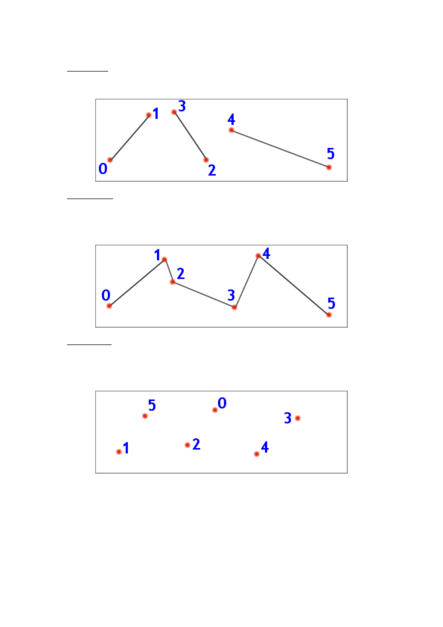
1. Line List
This is simple. Direct3D will draw a straight 1-pixel thick line between each pair of
vertices it finds in the stream. 0 & 1, 2 & 3, 4 & 5…
2. Line Strip
This is similar to the line list arrangement, but instead Direct3D will draw a 1-
pixel thick line between the current vertex and the previous vertex. So instead of
a set of unconnected lines you get a long “snake” of lines where each one is
joined together. 0 & 1, 1 & 2, 2 & 3, 3 & 4, 4 & 5…
3. Point List
This is as simple as geometry comes. It takes every vertex and renders it as a 1-
pixel ‘dot’ on the screen. Effectively it’ll work out to being a pixel plotter for now,
later on you can extend this to amazing effects with “point sprites” – smoke,
water, fire and other particle effects.
- 25 -
Introduction to Microsoft DirectX 9.0 (Managed Code)
written by Jack Hoxley ( Jack.Hoxley@DirectX4VB.com )
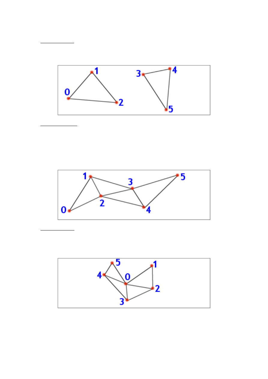
4. Triangle List
We shall be using this for the cube in the following sample code. Direct3D
interprets every triplet of vertices as describing a triangle and renders them
accordingly. No triangles are connected together. 0 & 1 & 2, 3 & 4 & 5
5. Triangle Strip
An extension of triangle lists, each triangle will now share the two previous
vertices of the previous triangle. The resultant effect is that all pairs of triangles
are joined together along a common edge – they appear as a strip. This
arrangement is a very useful optimisation, partly because fewer vertices need to
be stored but mostly because it allows the graphics cards to implement
optimisations regarding the number of vertices transformed, lit and clipped. 0 & 1
& 2, 1 & 2 & 3, 2 & 3 & 4, 3 & 4 & 5
6. Triangle Fan
This is similar to the Triangle Strip, but instead of sharing the previous 2 vertices
all triangles share the first vertex (0). This arrangement is particularly useful for
geometry that follows a common focus (a cone, a circle, a hexagon etc…). 0 & 1
& 2, 0 & 2 & 3, 0 & 3 & 4, 0 & 4 & 5
You need to get all 6 of these in your head – you’ll probably only ever use #4 and
#5, but it pays off to be at least remember that the other 4 exist.
- 26 -
Introduction to Microsoft DirectX 9.0 (Managed Code)
written by Jack Hoxley ( Jack.Hoxley@DirectX4VB.com )
Vertex Ordering in an Individual Triangle
Depending on which of the above arrangements you use, you’ll need to pay
particular attention to the order in which you store vertices. Sure, A triangle is
made up of 3 vertices – why does it matter which order the 3 are in? (it wouldn’t
matter if you drew it on paper) Direct3D adds an additional optimisation to the
rendering pipeline – back face culling.
As you’re probably aware, complex 3D scenes are made up of 100,000 triangles
or more, and it is quite likely that when rendered we won’t know if they’re facing
the camera or not (some are back facing). Take a cube for example, it has 6
sides, but we can only ever see 3 at a time: the other 3 are back facing. To save
drawing time (the process of plotting pixels) Direct3D cleverly removes the faces
we shouldn’t be able to see – saving on drawing them (and then drawing over
them) and saving on depth-buffer comparisons.
Because of this clever Direct3D optimisation, it is necessary to understand how it
works – so you can create your geometry accordingly. As you’ll see in the sample
code, you can use the Device.RenderState.CullMode to change to 1 of 3 culling
modes, the default being Cull.CounterClockwise – meaning it removes all
counter-clockwise faces.
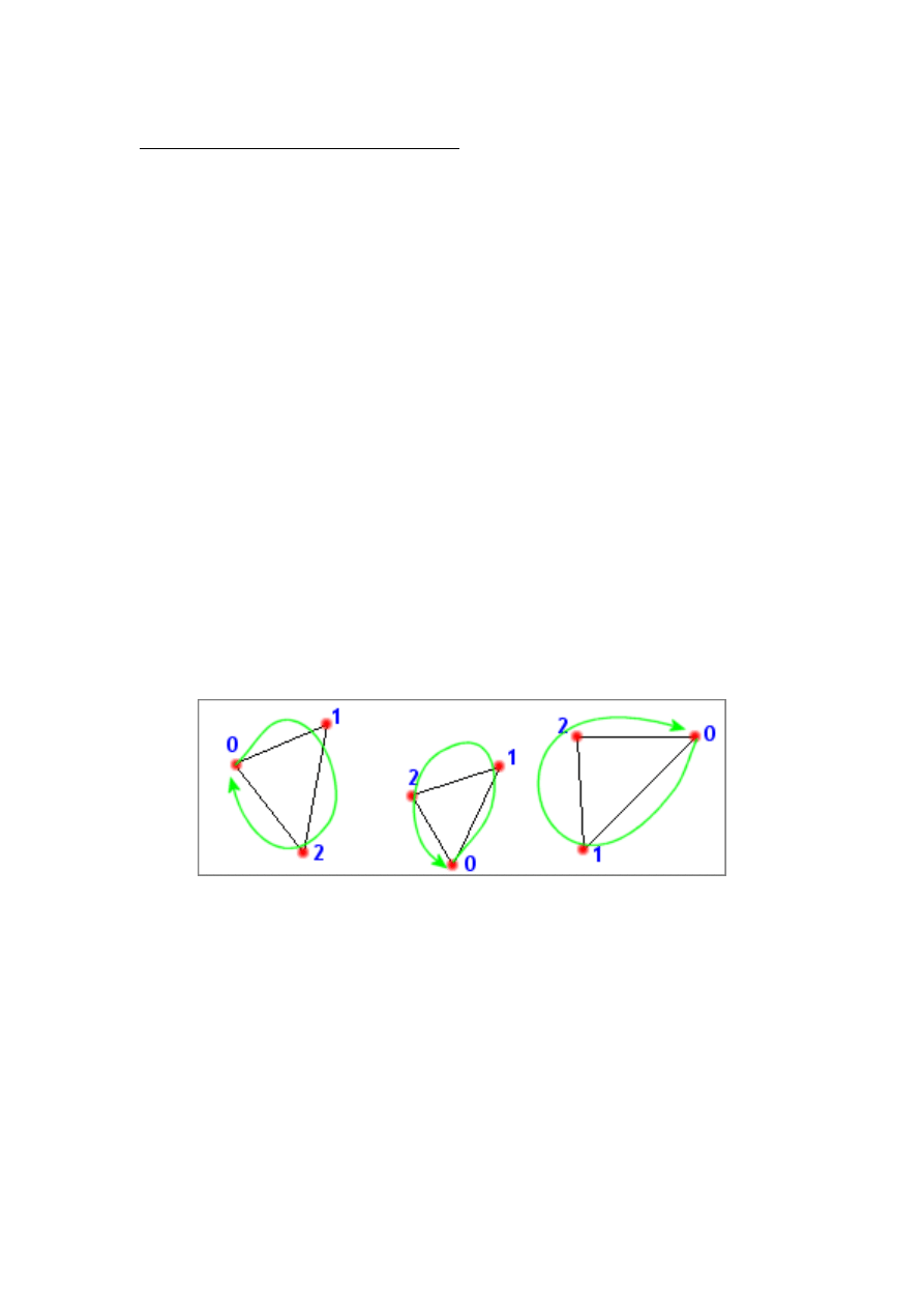
If you transform the 3 points of a triangle into screen-space (ie, they have their
2D coordinates as they’d be rendered on the screen), and you then draw a line
from vertex 0->1->2 (in the order arranged in memory) you’ll be able to make it
a clockwise or counter-clockwise pattern. If you have the culling set to counter
clockwise you’ll remove all those triangles that have a counter clockwise pattern,
if you have clockwise culling you’ll remove clockwise triangles. See the following 2
diagrams for an example:
The left-most diagram is clockwise – drawing a circle from 0->1->2 results in a
clockwise arrow. The Middle diagram is counter-clockwise and the right-most
diagram is clockwise.
It is usual to stick with counter-clockwise culling (in the above example, the
middle triangle would not be rendered) and design your models accordingly.
Industry-standard modelling packages (such as 3DS Max and trueSpace) export
their models with clockwise ‘winding’ such that they easily fit into a Direct3D
engine. It may be necessary (depending on the tools you use) to specify
clockwise culling.
No culling has its uses – particularly for some advanced effects (Such as those
involving semi-transparent surfaces), but for normal ‘solid’ geometry you
shouldn’t use it. It may seem like the easy way out – setting no-culling would
allow you to completely ignore this issue of geometry creation. However, in past
- 27 -

Introduction to Microsoft DirectX 9.0 (Managed Code)
written by Jack Hoxley ( Jack.Hoxley@DirectX4VB.com )
experience you can loose at least 40% of your rendering performance by
choosing this route. A drop from 200 to 120 frames per second isn’t that
amazing, but a drop from 40 to 26 frames per second will make a noticeable
difference (for lower-end systems).
Completing the Engine: loadGeometry()
Now that we’ve covered the specifics of geometry storage and rendering I’ll cover
the actual specifics – how to implement this in code. The code shown next looks
far more complicated than it actually is – I had to write out some of this on paper
before coding it to get it in the correct order.
loadGeometry() is the function in our class that is designed to handle all the
geometry loading and creation, by the time this function completes we should
have a complete set of geometry ready to be rendered.
Private
Sub
loadGeometry()
Try
'in this sample, we dont actually LOAD geometry from a file,
'rather we LOAD it into memory.
'[------------------------------------]
' LOAD 2D GEOMETRY INTO VBUFFERS
'[------------------------------------]
vbMenu =
New
VertexBuffer(
GetType
(CustomVertex.TransformedTextured), _
4, D3DDev, 0, _
CustomVertex.TransformedTextured.Format, _
Pool.Default)
Dim
v
As
CustomVertex.TransformedTextured() =
CType
(vbMenu.Lock(0, 0), _
CustomVertex.TransformedTextured())
Const
iMBWidth
As
Integer
= 158
Const
iMBHeight
As
Integer
= 93
'use the constructors to fill the data.
'laid out such that first line = coordinate (x,y,z,rhw)
'and second line = texcoord (u,v)
v(0) =
New
CustomVertex.TransformedTextured(0, 86, 0, 1, _
0, 2 / 127)
v(1) =
New
CustomVertex.TransformedTextured(iMBWidth, 86, 0, 1, _
iMBWidth / 255, 2 / 127)
v(2) =
New
CustomVertex.TransformedTextured(0, 86 + iMBHeight, 0, 1, _
0, iMBHeight / 127)
v(3) =
New
CustomVertex.TransformedTextured(iMBWidth, 86 + iMBHeight, 0, 1, _
iMBWidth / 255, iMBHeight / 127)
vbMenu.Unlock()
'[------------------------------------]
' LOAD 3D GEOMETRY INTO VBUFFERS
'[------------------------------------]
vbCube =
New
VertexBuffer(
GetType
(CustomVertex.PositionTextured), _
36, D3DDev, 0, CustomVertex.PositionTextured.Format, _
Pool.Managed)
'use CType() to typecast a pointer to the
'memory into an array of position&textured vertices
Dim
vCube
As
CustomVertex.PositionTextured() =
CType
(vbCube.Lock(0, 0), _
CustomVertex.PositionTextured())
'2a. Generate top plane
vCube(0) =
New
CustomVertex.PositionTextured(-0.5, 0.5, 0.5, 0, 0)
vCube(1) =
New
CustomVertex.PositionTextured(0.5, 0.5, 0.5, 1, 0)
vCube(2) =
New
CustomVertex.PositionTextured(-0.5, 0.5, -0.5, 0, 1)
vCube(3) =
New
CustomVertex.PositionTextured(0.5, 0.5, -0.5, 1, 1)
vCube(4) =
New
CustomVertex.PositionTextured(-0.5, 0.5, -0.5, 0, 1)
vCube(5) =
New
CustomVertex.PositionTextured(0.5, 0.5, 0.5, 1, 0)
'2b. Generate bottom plane
vCube(6) =
New
CustomVertex.PositionTextured(-0.5, -0.5, -0.5, 1, 0)
- 28 -

Introduction to Microsoft DirectX 9.0 (Managed Code)
written by Jack Hoxley ( Jack.Hoxley@DirectX4VB.com )
vCube(7) =
New
CustomVertex.PositionTextured(0.5, -0.5, 0.5, 0, 1)
vCube(8) =
New
CustomVertex.PositionTextured(-0.5, -0.5, 0.5, 0, 0)
vCube(9) =
New
CustomVertex.PositionTextured(0.5, -0.5, 0.5, 0, 1)
vCube(10) =
New
CustomVertex.PositionTextured(-0.5, -0.5, -0.5, 1, 0)
vCube(11) =
New
CustomVertex.PositionTextured(0.5, -0.5, -0.5, 1, 1)
'2c. Generate 'left' plane
vCube(12) =
New
CustomVertex.PositionTextured(-0.5, 0.5, -0.5, 0, 0)
vCube(13) =
New
CustomVertex.PositionTextured(-0.5, -0.5, -0.5, 1, 0)
vCube(14) =
New
CustomVertex.PositionTextured(-0.5, 0.5, 0.5, 0, 1)
vCube(15) =
New
CustomVertex.PositionTextured(-0.5, 0.5, 0.5, 0, 1)
vCube(16) =
New
CustomVertex.PositionTextured(-0.5, -0.5, -0.5, 1, 0)
vCube(17) =
New
CustomVertex.PositionTextured(-0.5, -0.5, 0.5, 1, 1)
'2d. Generate 'right' plane
vCube(18) =
New
CustomVertex.PositionTextured(0.5, 0.5, -0.5, 0, 0)
vCube(19) =
New
CustomVertex.PositionTextured(0.5, 0.5, 0.5, 1, 0)
vCube(20) =
New
CustomVertex.PositionTextured(0.5, -0.5, -0.5, 0, 1)
vCube(21) =
New
CustomVertex.PositionTextured(0.5, -0.5, 0.5, 1, 1)
vCube(22) =
New
CustomVertex.PositionTextured(0.5, -0.5, -0.5, 0, 1)
vCube(23) =
New
CustomVertex.PositionTextured(0.5, 0.5, 0.5, 1, 0)
'2e. Generate 'Back' plane
vCube(24) =
New
CustomVertex.PositionTextured(-0.5, 0.5, -0.5, 0, 0)
vCube(25) =
New
CustomVertex.PositionTextured(0.5, 0.5, -0.5, 1, 0)
vCube(26) =
New
CustomVertex.PositionTextured(-0.5, -0.5, -0.5, 0, 1)
vCube(27) =
New
CustomVertex.PositionTextured(0.5, -0.5, -0.5, 1, 1)
vCube(28) =
New
CustomVertex.PositionTextured(-0.5, -0.5, -0.5, 0, 1)
vCube(29) =
New
CustomVertex.PositionTextured(0.5, 0.5, -0.5, 1, 0)
'2f. Generate 'Front' plane
vCube(30) =
New
CustomVertex.PositionTextured(0.5, 0.5, 0.5, 1, 0)
vCube(31) =
New
CustomVertex.PositionTextured(-0.5, 0.5, 0.5, 0, 0)
vCube(32) =
New
CustomVertex.PositionTextured(-0.5, -0.5, 0.5, 0, 1)
vCube(33) =
New
CustomVertex.PositionTextured(-0.5, -0.5, 0.5, 0, 1)
vCube(34) =
New
CustomVertex.PositionTextured(0.5, -0.5, 0.5, 1, 1)
vCube(35) =
New
CustomVertex.PositionTextured(0.5, 0.5, 0.5, 1, 0)
vbCube.Unlock()
Catch
err
As
Exception
MsgBox("loadGeometry(): " + Chr(13) + Chr(13) + err.ToString())
Throw
New
Exception("could not complete loadGeometry()")
End
Try
End
Sub
The above code sample is considerably more complicated and ‘scary’ than it really
is. There are actually only 4 parts of this code that you need to pay attention to –
the rest are specific to this sample application, and to the process of creating a
cube.
The above function is split into two parts – firstly where we create a simple 2D
menu-bar, and the second where we create the cube. Both give different results,
yet both follow exactly the same programming.
Firstly, we need to create the vertex buffer – we have to tell Direct3D that we
want a new vertex buffer, we want it to store a specific type of vertex (vertex
buffers can only store one type of vertex at a time) and how many vertices
(which equates to how big the buffer will be).
vbCube =
New
VertexBuffer(
GetType
(CustomVertex.PositionTextured), 36, D3DDev, 0, _
CustomVertex.PositionTextured.Format, Pool.Managed)
We use the VertexBuffer class’ constructor to create a reference for our new
vertex buffer. The above line states: I want to create a buffer where all vertices
- 29 -

Introduction to Microsoft DirectX 9.0 (Managed Code)
written by Jack Hoxley ( Jack.Hoxley@DirectX4VB.com )
have a position and a texture coordinate, I want to store 36 of these vertices and
I want Direct3D to handle it’s position in memory for me. The GetType()
command tells the function what type of vertex we’ll be storing, the second
parameter ‘36’ is the number of vertices we’ll be storing, Pool.Managed indicates
that we want Direct3D to move our buffer from/to system memory and video-
memory accordingly. The CustomVertex class holds all the common types of
vertex – so that we don’t need to define them manually, have a look at it in the
object browser – there are quite a few different ones. It also holds the Flexible
Vertex Format (FVF) value for the vertex type, a number that we’ll need to use
later on.
Secondly, we lock the vertex buffer and retrieve a pointer to the vertex buffer’s
data. This will become a common theme in Direct3D – the process of locking a
resource, filling it with data, and then unlocking it. To lock the vertex buffer we
use this line of code:
Dim
vCube
As
CustomVertex.PositionTextured() =
CType
(vbCube.Lock(0, 0), _
CustomVertex.PositionTextured())
CType() is VB’s odd way of type-casting variables, but basically, we use the
Lock(0,0) call to lock the vertex buffer at the start (ie, index 0) and with no
special parameters. Whilst it’s not obviously subscript-checked, we can access
vCube(0) to vCube(35) as being the 36 available vertex-storage locations.
The third stage of geometry creation is to fill in this array of vertices with
meaningful data. In the sample code we’ll be making it a cube – out of 36
vertices. This is completely up to you – and it is where your choice of rendering
technique will first apply. The arrangement I’m using for the sample code is a
triangle-list – the simplest possible, it is more optimal to use triangle-strips and
potentially two triangle fans.
The final stage is possibly the simplest – an unlock command. If we lock the
vertex buffer, and acquire a pointer to its memory we must at some point free
this pointer. It makes good sense to free it as soon as we’re finished using it, but
more importantly we have to free it before we render. If we attempt to render the
vertex buffer while it’s locked you’ll find Direct3D throwing you a nasty
DirectXException.
- 30 -

Introduction to Microsoft DirectX 9.0 (Managed Code)
written by Jack Hoxley ( Jack.Hoxley@DirectX4VB.com )
In More Depth: Textures
Now we’ve covered geometry, we need to cover the basics of textures; as
mentioned earlier – geometry only really comes alive when you make clever use
of textures. It will be many, many years from now before we can render realistic
3D models with geometry alone (and no textures).
One useful thing to note before we work with textures; optimally textures are
stored with dimensions of 2
n
. The width and the height are powers of 2. 128x128,
256x256, 512x1024, 256x128 etc… This allows the hardware to use a few
optimizations to further speed up rendering of texture surfaces. Modern hardware
doesn’t always have this requirement (it will allow “non 2-to-the-power-n”
textures), but if you opt to use such a texture you should expect it NOT to
perform as well as one that is 2
n
. You don’t need to store your textures as 2
n
sizes, but they will (unless you specify otherwise) be converted to a 2
n
size by
Direct3D – so it generally helps to get used to this scheme early on. It is also
necessary to enumerate support for texture sizes – most hardware beyond the
GeForce-2 will allow textures up to and beyond 1024x1024 (big enough for most
situations) but it is still best to enumerate. Direct3D 9 is restricted to DDI 7 level
drivers, but there are a few (such as the popular ‘voodoo’ series) that have rather
odd texture requirements (256x256 maximum size).
How is a Texture Represented On-Disk
Textures on disk are nothing but standard image files – something you’ve
probably come across 1000’s of times. Typically they’ll be represented as two-
dimensional arrays of pixels – bitmaps. Many modern formats use lossy (or non-
lossy) compression schemes to reduce the size stored on disk. A perfect copy of a
printable photo would normally occupy around 24mb, however digital cameras
often store them in around 1/50
th
of this size – 400kb.
With Direct3DX – the helper library that ships with Direct3D, you don’t need to
worry too much about the format of the texture; as long as you stick to a
common format (BMP, TGA, GIF, JPG etc…) it’ll probably be able to load it. With
this in mind, the only compromise is regarding the quality and the size on the
disk (note, size in memory is not involved here). If you intend to ship your
product on a CD, you can very easily fill up 650mb with 3,500 medium-low
resolution textures alone (it’s not as difficult as you might think for a complete 3D
world / game).
There is one additional format to be aware of – Direct Draw Surface (DDS)
format. These files store (on disk) the same data as would be stored in memory
by the graphics card. This is a surprisingly powerful method – if the data is stored
on disk the same as it is stored in memory it can be loaded extremely quickly. It
also allows the artists to specify exactly how Direct3D will represent the color; if
the alpha channel has 2-bit accuracy, you can design it for 2-bit accuracy from
the start (rather than let Direct3DX sample an 8bit alpha channel down to 2bit as
is the case for TGA files). If you want to create DDS files, it is best to use the
‘DXTex’ tool shipped with the SDK; there are plugins for photoshop and other
graphics packages that allow you to directly export from these tools – but you’ll
have to search for these.
- 31 -

Introduction to Microsoft DirectX 9.0 (Managed Code)
written by Jack Hoxley ( Jack.Hoxley@DirectX4VB.com )
How is a Texture Represented in Memory
How textures are stored on disk is similar, but subtly different to how they are
stored in memory. It is important to appreciate this difference and it’s
consequences.
The first important difference – almost all textures will be stored in bitmap format
in memory. For a rendering system that attempts to give the greatest
performance possible it can’t be required to decompress often complex
compression schemes just to render a few 100 triangles. There are 5 texture
formats that are compressed – DXT1…5. They still offer good performance, and
DXT1 also offers 6:1 compression, which can be extremely useful when you want
to fit 256mb of textures onto a 64mb graphics card.
Texture formats are represented by the Format enumeration, which has over 40
possible textures formats defined. Direct3D9 introduces a few complications to
what used to be a relatively simple rule – but for simple applications like ours
these need not bother us. All of the formats described by this enumeration are
divided into the follow names:
<tag 1><bits 1><tag 2><bits 2> … <tag n><bits n>
Where tag is the single-letter name for the channel (A, R, G, B, Y, U, V and X)
and bits is the number of bits-per-pixel allocated to store the amount of that
channel required for that pixel.
X8
R8
G8
B8
Is a good example – one that you’ll probably become familiar with quite quickly.
It states: 8 bits for the ‘X’ channel, 8 bits for the ‘R’ channel, 8 bits for the ‘G’
Channel and 8 bits for the ‘B’ channel. Where X is an unused component, R is
Red, G is Green and B is blue. The number of bits indicates the space, stored as
an integer, allocated for that channel – thus in the above example there are 8
bits for the blue channel – 2
8
possible colors (256). It therefore follows that if you
add up all the numbers in the format descriptor you’ll get the number of bits per
pixel – in this case it’s 32bits. You’ll generally find common formats follow the 2
n
rule – 8,16,32,64 or 128 bits per pixel.
Direct3D9 has added 6 new formats that differ from this rule:
A16R16G16B16F
A32R32G32B32F
G16R16F
G32R32F
R16F
R32F
They all have the same naming scheme – except they have an ‘F’ appended to
the end. These six formats are all floating-point numbers. The A32R32G32B32F
format stores 4 Singles (in normal programming terms) per pixel – 1 float per
channel; this allows for much higher color fidelity and generally much better color
for rendered images – something that I hope developers make good use of in the
near future. You won’t need to use these in anything but the most advanced
graphics engines.
As a summary: when you create a texture in memory you’ll assign it a format (as
discussed above) and it’ll be stored accordingly. If you have a 32mb card you’ll
- 32 -

Introduction to Microsoft DirectX 9.0 (Managed Code)
written by Jack Hoxley ( Jack.Hoxley@DirectX4VB.com )
probably have around 20-25mb of memory available for textures, you’ll need to
decide how many textures of a given size and format you can fit into this space.
If you can fit an entire level/world’s textures in at the same time you’ll have to
devise an algorithm to load only the most important ones at any given time.
Texture Coordinate Theory
Now that we understand the way that data is stored both on disk and in memory,
we have to understand how Direct3D will be using these textures when applied to
geometry.
We have covered the idea of vertices – and the way that they are the
fundamental building block for all geometry rendered by Direct3D. Every vertex
has a set of properties – position, color, lighting values and texture coordinates.
It is texture coordinates that are important for our work in this section. A texture
is defined in two dimensions, so we’ll have a 2D coordinate for each vertex
associated with the texture we’ll be rendering on it – these coordinates are known
as the U and V coordinates (NOT X and Y).
As mentioned, a triangle, even if we define it in 3D-space, is still a planar two-
dimensional object (it is flat). If we take the 3 vertices that make up a triangle,
and examine the associated texture coordinates we can work out an area of the
texture (stored in memory) that we will map onto the triangle when it is
displayed on the screen. The area specified by the coordinates can be 500 square
pixels of 2 square pixels – it doesn’t matter. Direct3D will filter the texture
accordingly so that you get the correct piece of texture displayed on the triangle.
The surprising part about texture coordinates (if you’ve never come across them
before!) is that they’re not measured in pixels. Instead, they’re measured as
single-precision floating-point numbers in the range 0.0 to 1.0 (you can use
values outside this range, but that’s beyond the current level). This system of
measuring texture coordinates works as a scalar – if you specify 0.0 you’ll
reference the top or left of the texture, if you specify 1.0 you’ll specify the bottom
or right of the texture (the maximum width/height), if you specify 0.5 you’ll
reference the middle of one dimension of the texture.
U , V
0.0 , 0.0
= top left
1.0 , 0.0
= top right
0.0 , 1.0
= bottom left
1.0 , 1.0
= bottom right
0.5, 0.5
= absolute middle
It may seem odd that you don’t use pixel-measurements to specify texture
coordinates, but if you think about it (and appreciate 3D graphics concepts) it
does make a lot of sense. Textures when you load them, will be of the size you
expect – but there may also be several identical copies of the texture at lower
resolutions in memory. This has been a common feature for some time – Mip
Mapping (Latin for ‘much in little’); if you create a texture of size 256x256
Direct3D will silently create smaller, identical, textures of 128x128, 64x64,
32x32, 16x16, 8x8, 4x4, 2x2, 1x1. The reason for this is that when a triangle
gets further from the camera the area it occupies in the final image is significantly
smaller – so there’s no point in trying to map a very high-detail texture to a very
- 33 -

Introduction to Microsoft DirectX 9.0 (Managed Code)
written by Jack Hoxley ( Jack.Hoxley@DirectX4VB.com )
small space on-screen. Direct3D will dynamically choose which “level” of the mip-
map should be used based on the size of the triangle on the screen. This may
seem odd, but it works out as giving a much higher final-image quality. It also
allows you to change the texture size (at load-time) and not worry about altering
texture coordinates – you can store a 1024x1024 texture on the disk, but if the
system can’t handle it you can load it in as a smaller size and the texture
coordinates will behave as if nothing has changed and the end result will be
almost identical (although probably more blurred due to lower resolution data).
So, in summary, for every texture we’ll specify a U and a V coordinate for the
piece of texture we want to use. The code shown (for creating a cube) in the
geometry section earlier actually included texture coordinates. The last two
parameters of the vertex-constructor were the U and V coordinates.
Get your head around this… for its now going to get complicated again. It is
perfectly possible to have more than 1 texture per triangle. In fact, it’s possible to
have 8 textures per triangle. In practice, you’ll be unlikely to use more than 3
textures (and that’s for quite advanced graphics). You can ignore this for the
meantime – but it is useful to know that it is possible to have more than one set
of texture coordinates per texture, and that it’s also possible to have no texture
coordinates for a vertex.
Completing the Engine: loadTextures()
loadTextures() is actually quite a simple piece of code – the real ‘genius’ is in
using the textures – not loading them. It is interesting to note that Direct3D
doesn’t actually load the texture for you – Direct3DX (the helper library) does
everything related to moving/converting the data stored on the disk to the
location in memory.
The only ‘tricky’ part is the inclusion of enumeration for texture formats. The
Format class exposes 40+ possible texture formats to use, but this is no
guarantee that the target hardware will actually be able to use data in this
format. Before loading a texture into memory with a particular format it is best to
check to see if the device will later be able to render from it.
CheckDeviceFormat( ) is the function that we can use to decide if a texture
format is suitable for the current device. There is the odd exception whereby a
device does support 16bit textures but won’t allow us to use them with a 32bit
display mode – this will also be exposed by this function.
Public Shared Function
CheckDeviceFormat( _
ByVal
adapter
As Integer
, _
ByVal
deviceType
As
DeviceType, _
ByVal
adapterFormat
As
Format, _
ByVal
usage
As
Usage, _
ByVal
resourceType
As
ResourceType, _
ByVal
checkFormat
As
Format _
)
As Boolean
Is the actual function prototype. adapter is almost always 0 (signifying the
primary display hardware). devicetype is going to be ‘Hardware’; adapterformat
will be the display mode that you selected at the start (and was stored in the
back buffer format member of PresentParameters). usage will be ‘0’ for default
(and indicating no special usage), resourcetype will be ‘Textures’ and
checkformat is the format that we actually want information regarding.
- 34 -

Introduction to Microsoft DirectX 9.0 (Managed Code)
written by Jack Hoxley ( Jack.Hoxley@DirectX4VB.com )
The function will return true or false depending on whether checkformat is
compatible with the specified adapter and display mode. Simple as that.
The sample code only uses 3 textures – one for each cube, and one for a menu.
They are stored as 2
n
-sized 24bit .bmp textures. The code for loading them is as
follows on the next page:
- 35 -

Introduction to Microsoft DirectX 9.0 (Managed Code)
written by Jack Hoxley ( Jack.Hoxley@DirectX4VB.com )
Private
Sub
loadTextures(
ByVal
AdapterFmt
As
Format)
'attempt to load the menu texture
If
D3DRoot.CheckDeviceFormat(0, _
DeviceType.Hardware, _
AdapterFmt, _
0, _
ResourceType.Textures, _
Format.A8R8G8B8 _
)
Then
texMenu = TextureLoader.FromFile(D3DDev, _
Application.StartupPath + "\menubar.bmp", _
256, 128, 1, 0, _
Format.A8R8G8B8, Pool.Managed, _
Filter.None, Filter.None, _
Drawing.Color.Magenta.ToArgb())
ElseIf
D3DRoot.CheckDeviceFormat(0, _
DeviceType.Hardware, _
AdapterFmt, _
0, _
ResourceType.Textures, _
Format.A1R5G5B5 _
)
Then
texMenu = TextureLoader.FromFile(D3DDev, _
Application.StartupPath + "\menubar.bmp", _
256, 128, 1, 0, _
Format.A1R5G5B5, Pool.Managed, _
Filter.None, Filter.None, _
Drawing.Color.Magenta.ToArgb())
Else
Throw
New
Exception("…")
End
If
'attempt to load the cube textures
If
D3DRoot.CheckDeviceFormat(0, _
DeviceType.Hardware, _
AdapterFmt, _
0, _
ResourceType.Textures, _
Format.X8R8G8B8 _
)
Then
texCube1 = TextureLoader.FromFile(D3DDev, _
Application.StartupPath + "\cube1.bmp", _
256, 256, 1, 0, _
Format.X8R8G8B8, Pool.Managed, _
Filter.Linear, Filter.Linear, 0)
texCube2 = TextureLoader.FromFile(D3DDev, _
Application.StartupPath + "\cube2.bmp", _
256, 256, 1, 0, _
Format.X8R8G8B8, Pool.Managed, _
Filter.Linear, Filter.Linear, 0)
ElseIf
D3DRoot.CheckDeviceFormat(0, _
DeviceType.Hardware, _
AdapterFmt, _
0, _
ResourceType.Textures, _
Format.R5G6B5 _
)
Then
texCube1 = TextureLoader.FromFile(D3DDev, _
Application.StartupPath + "\cube1.bmp", _
256, 256, 1, 0, _
Format.R5G6B5, Pool.Managed, _
Filter.Linear, Filter.Linear, 0)
texCube2 = TextureLoader.FromFile(D3DDev, _
Application.StartupPath + "\cube2.bmp", _
256, 256, 1, 0, _
Format.R5G6B5, Pool.Managed, _
Filter.Linear, Filter.Linear, 0)
Else
Throw
New
Exception("…")
End
If
End
Sub
- 36 -

Introduction to Microsoft DirectX 9.0 (Managed Code)
written by Jack Hoxley ( Jack.Hoxley@DirectX4VB.com )
The source code is actually divided into two sections only because there is a
subtle difference for 1 of the 3 textures that we’ll be loading. Transparencies.
As you may have noticed – all textures so far have been described as either
square or rectangular grids of pixels. This is fine for most situations, but there are
a number of cases where this is not entirely useful. Some complex patterns (such
as leaves on a plant) would require an incredibly high polygon count if all textures
were mapped as a solid image. It would make much more sense to render a
slightly larger (and simpler) polygon and ‘skip’ a certain number of pixels so that
only a portion of the texture was actually visible giving the illusion of a much
higher-detailed mesh than that being used.
I’ve mentioned earlier in this section the ‘A’ channel in textures – the alpha
channel. This channel never directly contributes to the final color rendered on the
screen, rather it is fundamental in a set of equations that can be performed on
every pixel rendered – alpha blending operations. These allow for a number of
subtle per-pixel effects – color fades and alterations, and topically, optional
transparency.
We can specify values in the ‘A’ component to indicate whether a pixel is
transparent or not. If it is deemed as transparent Direct3D won’t render it to the
screen. If you look back to the previous page, the first set of If ... End If
statements examine two formats: A8R8G8B8 and A1R5G5B5 – 32bit and 16bit
(respectively) texture formats that allow at least one bit of alpha precision. 1 bit
allows for two states – on/off yes/no. For transparencies we need only two states
– transparent or opaque. Thus we create a texture with at least 1 bit of alpha
precision, if we can’t do this then we deem the operation a failure. The 32bit
format has 8bits of precision, but this is necessary – the only common 32bit
format with an alpha channel allocates it 8bits (the A2R10G10B10 format is new
and not widely supported).
We also need to specify a color value for the last parameter in the FromFile()
function. Note that for the first texture it is magenta, and for the remaining two
textures it is 0. This last parameter tells Direct3DX to examine every pixel loaded
– if it’s color is the same as the color key (magenta) we make it transparent,
otherwise we make it opaque. If you open up “menubar.bmp” in an image editor
you’ll see that the majority of the texture is magenta in color – if we were to
render any of this to the screen it would not appear because the loader has
deemed it transparent.
Two lines in the initialiseDevice() function configure the transparent
rendering:
D3DDev.RenderState.SourceBlend = Blend.SourceAlpha
D3DDev.RenderState.DestinationBlend = Blend.InvSourceAlpha
We’ll discuss the actual rendering of these textures in the next-but-one section.
The remaining two textures that we load don’t need an alpha channel –they’re
solid textures. As such we can stick to the common 32bit and 16bit textures:
X888 and 565 formats.
The TextureLoader class is the part of the Direct3DX library that allows us to
create a Texture object from either a stream (data already in memory) or from a
file on the disk. The FromFile() function is overloaded 5 times to allow us various
ways of creating files. In the above sample code I’ve used on of the more
complex overloads – it was necessary to explicitly state what options I wanted to
- 37 -

Introduction to Microsoft DirectX 9.0 (Managed Code)
written by Jack Hoxley ( Jack.Hoxley@DirectX4VB.com )
use for textures (this will continue to be necessary for any special formats,
including alpha-channel textures). I could have made the loadTextures() function
considerably simpler by using the 5
th
overload:
Public Shared Function
FromFile( _
ByVal
device
As
Device, _
ByVal
srcFile
As String
_
)
As
Texture
texMenu = TextureLoader.FromFile(D3Ddev, pplication.StartupPath + "\menubar.bmp")
A
texCube1 = TextureLoader.FromFile(D3Ddev, Application.StartupPath + "\cube1.bmp")
texCube2 = TextureLoader.FromFile(D3Ddev, Application.StartupPath + "\cube2.bmp")
However, by using this trivial loading mechanism I would not be allowed to
specify an alpha channel and color key for texMenu.
- 38 -

Introduction to Microsoft DirectX 9.0 (Managed Code)
written by Jack Hoxley ( Jack.Hoxley@DirectX4VB.com )
Matrices Revisited
Matrices, as mentioned earlier in this tutorial area a way of using a single set of
geometry mutliple times to appear as though it were a completely different
entity. You can use a transformation matrix to render, what appears to the user,
as three different models from the same original source data.
However, it’s not (as you might have guessed) as simple as it seems. Matrix
operations in D3D follow pretty-much exactly the same rules as they do for pure
mathematics. If you’re not familiar with these rules, you’ll very quickly get used
to them.
Order Counts
The first fact about matrices that you need to appreciate is this:
A*B is not equal to B*A
Unlike the majority of pure mathematics, the multiplication operation is not
commutative. You have to pay attention to the order that you multiply matrices.
This is particularly important because to create a final transformation matrix we
will use several smaller (and simpler) matrix transformations multiplied together.
The above example could be:
Rotation_X*Translation is not equal to Translation*Rotation_x
If you think about it, if you rotate an object and then translate it you’ll be left
with (at the translation point) a rotated object. If you translate then rotate you’ll
get an object that is rotated a given distance from the origin. In animated terms,
Rotation then translation will give you a spinning object at any given point in 3D
space. Translation then rotation will give you an object that rotates around the
origin at the distance specified by the translation matrix.
This subtle difference is extremely important. It matters a great deal which order
you specify the various transformation matrices. We’ll be dealing with (and you’re
unlikely to need to bother with) world transformation matrices – view and
projection matrices can be formed in one step (and thus don’t need any
multiplication). In general, for a world transformation you’ll use the following
formula:
1) Scale
2) rotation (x,y,z)
3) translation
There is no reason that you need to stick to this pattern, but it does (75% of the
time) yield the result that you’d expect. Swapping number 2 and 3 on the above
list can give interesting results.
The sample code that you’ll see in a minute offers two different ways of
translating the same geometry. It is well worth your time to experiment with
these methods – and the order in which they are applied.
- 39 -

Introduction to Microsoft DirectX 9.0 (Managed Code)
written by Jack Hoxley ( Jack.Hoxley@DirectX4VB.com )
The D3D Math Helper Library
Matrix math is an ugly subject – there’s no other way to describe it. The theory is
understandable, but in practice it’s either plain confusing or requires too many
calculations to be possible on paper. The three transformations: scaling, rotation
and translation are all different and respectably complicated – it is far beyond the
scope of this tutorial to explain them. We shall, however, use the Direct3DX math
library to do all the hard work for us.
The Matrix structure has over 25 functions that we can use to create a
transformation matrix. Of which, only 7 are of particular use:
Multiply()
- puts two different matrices together
Identity()
- the most basic transformation matrix
RotateX()
- rotates the matrix around the X-axis
RotateY()
- rotates the matrix around the Y-axis
RotateZ()
- rotates the matrix around the Z-axis
Scaling()
- scales the matrix by a given factor
Translation()
- translates the matrix a given distance
The above are all fairly self-explanatory, and where ‘matrix’ is involved you can
read it as being the object/geometry you’re about to render. I.e. “rotates the
matrix around the y-axis” is effectively the same as “rotates the geometry around
the y-axis”.
Most of the functions listed above have overloads – you can specify 3 singles or a
3-part vector – both are acceptable. A useful mechanic to remember, when
putting several matrices together is:
matCube1 = Matrix.Multiply(matCube1, Matrix.Scaling(3, 3, 3))
Using this system, you don’t need a temporary matrix to store the scaling factor.
More importantly, you can put many of these lines together (where the 2
nd
parameter is the new modifier) and keep very clean and readable code.
Completing the Engine: oneFrameUpdate()
Before we get stuck in, it’s important to appreciate how the world transformation
is applied to the geometry that you render. All transformation matrices are set
using the Device.Transform interface – world, view and projection matrices as
well as a few others. Once a matrix has been “set” to the device, all subsequent
geometry is affected by it – if you set a rotation matrix for the world matrix ALL
geometry from that point onwards is rotated. This somehow seems to get people
very confused – they don’t seem to see how you can render multiple objects with
different transformations. The key is to appreciate that you can change the
transformation matrix as many times in a frame as you want, and as soon as it’s
changed all geometry will be affected by the new matrix and not the old one. To
outline this further, take this piece of pseudo-code:
<Begin the frame>
<Set matrix 1>
<Render object 1>
<Set matrix 2>
<Render object 2>
…
- 40 -

Introduction to Microsoft DirectX 9.0 (Managed Code)
written by Jack Hoxley ( Jack.Hoxley@DirectX4VB.com )
<Set matrix n>
<Render object n>
<End the frame>
For this reason I added two cubes to the sample code – both using different
matrices. Follow the code structure used by the sample and you can easily see
how to render multiple pieces of geometry with different transformations.
Also to note is how I structured the graphics engine to handle transformation
calculation. For the sample, both the view and projection matrices remain static –
such that we can calculate that in initialiseEngine() and then ignore them.
The world matrices (one for each cube) need to be calculated every frame. It
makes for cleaner code if you split the rendering and the updating code apart;
hence the oneFrameUpdate() and oneFrameRender() functions.
Public
Sub
oneFrameUpdate()
If
Not
bInitOkay
Then
Throw
New
Exception("…")
'general variables
Dim
matTmp
As
Matrix
'calculate the current rotation angles for the two cubes
cube1Angle += ((Environment.TickCount() - lastFrameUpdate) / 1000) * cube1Speed
cube2Angle += ((Environment.TickCount() - lastFrameUpdate) / 1000) * cube2Speed
lastFrameUpdate = Environment.TickCount()
'calculate cube1's matrix
matCube1 = Matrix.Identity()
matCube1 = Matrix.Multiply(matCube1, _
Matrix.Scaling(3, 3, 3))
matCube1 = Matrix.Multiply(matCube1, _
Matrix.RotationX(cube1Angle * (Math.PI / 180)))
matCube1 = Matrix.Multiply(matCube1, _
Matrix.RotationY(cube1Angle * (Math.PI / 180)))
'calculate cube2's matrix
matCube2 = Matrix.Identity()
matCube2 = Matrix.Multiply(matCube2, _
Matrix.Scaling(4, 5, 0.75))
matCube2 = Matrix.Multiply(matCube2, _
Matrix.Translation(-8, -4, 0))
matCube2 = Matrix.Multiply(matCube2, _
Matrix.RotationZ(cube2Angle * (Math.PI / 180)))
'calculate the current framerate
If
(Environment.TickCount() - iLastFPSCheck >= iFPSProfileSpeed)
Then
iLastFPSCheck = Environment.TickCount()
iFrameRate = iCurrCnt * (1000 / iFPSProfileSpeed)
iCurrCnt = 0
End
If
iCurrCnt += 1
End
Sub
As you can see from the above code listing, oneFrameUpdate() is divided into 3
main parts, of which only the first two are concerned with
matrices/transformations.
I’ve implemented a time-based modeling system for this sample which is slightly
more complicated than some animation systems, but it pays off if you take the
time to learn how the equation works. It, fairly simply, uses a couple of constants
to increment the two angle variables at a constant rate – say 50 degrees every
second. If the frame rate is extremely high or extremely low the matrix will still
only ever rotate by 50 degrees in a second. The other animation methods involve
adding a fixed amount per frame and then “capping” the frame rate. This way, if
the application is capped to 45fps, you need at 1 to the angle each frame to get it
moving at 45 degrees per second. This only works properly when the frame rate
- 41 -

Introduction to Microsoft DirectX 9.0 (Managed Code)
written by Jack Hoxley ( Jack.Hoxley@DirectX4VB.com )
is constant (I.e. never fluctuates from 45) and most importantly never falls
below. For a fast computer this is quite possible, but there will still be moments
when the frame rate drops and/or you’re end user is not using a powerful-enough
PC; in these cases the animation will go completely wrong – and you’ll get no end
of odd looking results and physics calculations/models can be completely thrown
by this system.
The second and third parts actually construct the two matrices: matCube1 and
matCube2. We don’t actually set either matrix to the device in this code – we just
construct them and store them in memory for use later on.
Cube 1 is scaled first – such that it will be a cube of 3x3x3 units (if you look back
at the loadGeometry() code you’ll see that the cube is of size 1). It is then
rotated about the X axis, and then the Y axis. There is no translation. The net
result (as you’ll see when you run the sample code) is a cube of equal dimensions
rotating around one position (the origin).
Cube 2 is scaled first – except this time it isn’t uniformly scaled, it’s Z-size is
smaller and the X & Y sizes are different. It is therefore more of a rectangular
shape / flat cube. This object is then translated away from the origin by [-8,-4,0]
and then rotated about the Z axis. This gives the interesting effect of the cube
‘orbiting’ around the first cube – rotations are always with respect to the world
origin, so if you translate first it will still rotate around this point.
- 42 -

Introduction to Microsoft DirectX 9.0 (Managed Code)
written by Jack Hoxley ( Jack.Hoxley@DirectX4VB.com )
Finishing it all off
At this point in the tutorial we have covered almost all of the supporting code for
a Direct3D graphics engine. We can initialise the graphics, load textures and
create some simple geometry and we can configure a pair of transformation
matrices. However, this is still merely the supporting code – the meat of any D3D
engine is this next (and last) section.
If you play a commercial game, 99.9% of the graphics processing time will be
spent rendering – not loading media or initialising objects. Thus we must spend
the most time working on (and fine-tuning) the rendering functions. To fully
utilize the power of modern graphics cards you have to be very careful how you
design and implement your code – a slightly sloppy, or inefficient function can
make the difference between interactive and non-interactive graphics or more
importantly it can determine what the lowest-spec PC you can ship your product
for. The teams that work on the famous graphics engines – Doom/Quake/Unreal
(all FPS games) spend months working on algorithms to fine tune and optimize
rendering performance.
The techniques that graphics programmers employ to squeeze every last drop out
of your GeForce-4 are often well documented online; check out the references
section for some starting places. I can’t go into detail on any of these techniques
– and for the purposes of learning they’ll only serve to confuse.
Issues When Rendering to the Screen
Draw order is one of the first problems that you can come across when you step
into 3D graphics. I’ve mentioned draw order before – with respect to the depth
buffer features. Whilst the depth buffer does a great job, it’s far from perfect for
all situations. There are two factors to be aware of.
Firstly, the Z-Buffer is only informed as far as what has already been rendered
and has no knowledge regarding what will be rendered in the future; thus if you
render a complex object and then render a simple cube in front of it (such that it
blocks the camera’s view of the complex object) BOTH objects will in fact be
rendered – the depth buffer does not know (and hence will still allow rendering)
that the first object will not be visible in the final image. This is known as
overdraw – you can count overdraw for any pixel on the screen and you’ll
generally find that it’s in the region of 2-3 (each pixel in the final image has been
over drawn 2 or 3 times that frame). You can expect a certain degree of
overdraw, but if forgotten about it can get out of control. Occlusion
Culling/Queries have been introduced into D3D9 to allow some hardware to
reduce this problem – but it’s a fairly advanced topic.
The second factor to consider is that semi-transparent objects are very
dependent on draw order, and the depth buffer cannot help them at all. If an
object has a surface with semi-transparent textures or transparent areas (as
discussed earlier in the texturing section) then it’ll need to be drawn last. When
the color is written to the screen using blending equations, it can only use the
colors that already exist on the screen (objects rendered before). As a real-world
example, if you render a window you need to render everything you can see
through the window first. If you don’t you’ll end up with some objects being
blurred/faded by the window, and some objects appearing completely normally
(or not at all).
- 43 -
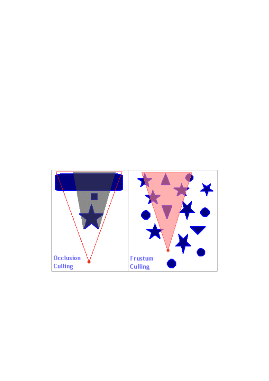
Introduction to Microsoft DirectX 9.0 (Managed Code)
written by Jack Hoxley ( Jack.Hoxley@DirectX4VB.com )
Another issue that you will come across as soon as you start creating large
and/or complex worlds is that of invisible geometry. It’s common-sense to realise
that you only want to render objects that you’ll actually see – any that are
behind/beside the camera and can’t be seen don’t need to be rendered. If you do
render these objects (commonly known as brute-force rendering) then you’ll
waste a huge amount of processing time. The objects will be ‘removed’ before
any texturing, blending or shading operations are computed, but they will still be
transformed, lit and clipped – and will also occupy a certain amount of memory
bandwidth in the process. If you could avoid sending this geometry to be
rendered you could cut out a lot of unnecessary work – which will make your
application run much faster and/or can allow you to spend more time on the
geometry that does appear on screen (more complex geometry, more textures,
more special effects).
However, how do you tell which objects can/can’t be rendered? This is quite a
complicated area, and isn’t included in this tutorial – but you can implement it
fairly easily if you read through some sample code/tutorials available on the net.
Frustum culling is a common technique and quite easy to understand, occlusion
culling, portal culling, BSP Tree’s, Quadtree’s and Octree’s are even more efficient
but generally more complicated to understand and implement. The basic idea
behind most of the algorithms is to ‘reject’ geometry at the application stage and
before attempting any 3D-based rendering – any additional computing done by
the application can be expensive but far outweighs the potential loss of rendering
invisible geometry.
In the above image I’ve outlined (on the right) the most common type of culling
and (on the left) one of the most advanced types of culling. Frustum culling works
by testing all rendered objects (all of the blue stars, triangles and circles) against
the visible area (the pink triangle); if an object is totally or partially in the pink
area it is rendered, if it’s outside the area it isn’t rendered. In the above diagram
7 of the 15 objects will be rejected – reducing the number of objects transformed,
lit and clipped by 47%. Occlusion culling works by taking each rendered object
and creating an occluded zone (the dark gray area), almost like casting a
shadow; all subsequent objects (such as the small blue square) are tested against
this zone – if it’s inside it is rejected, if it’s outside it’s rendered. This algorithm
works best when you draw objects in a front-back order.
- 44 -
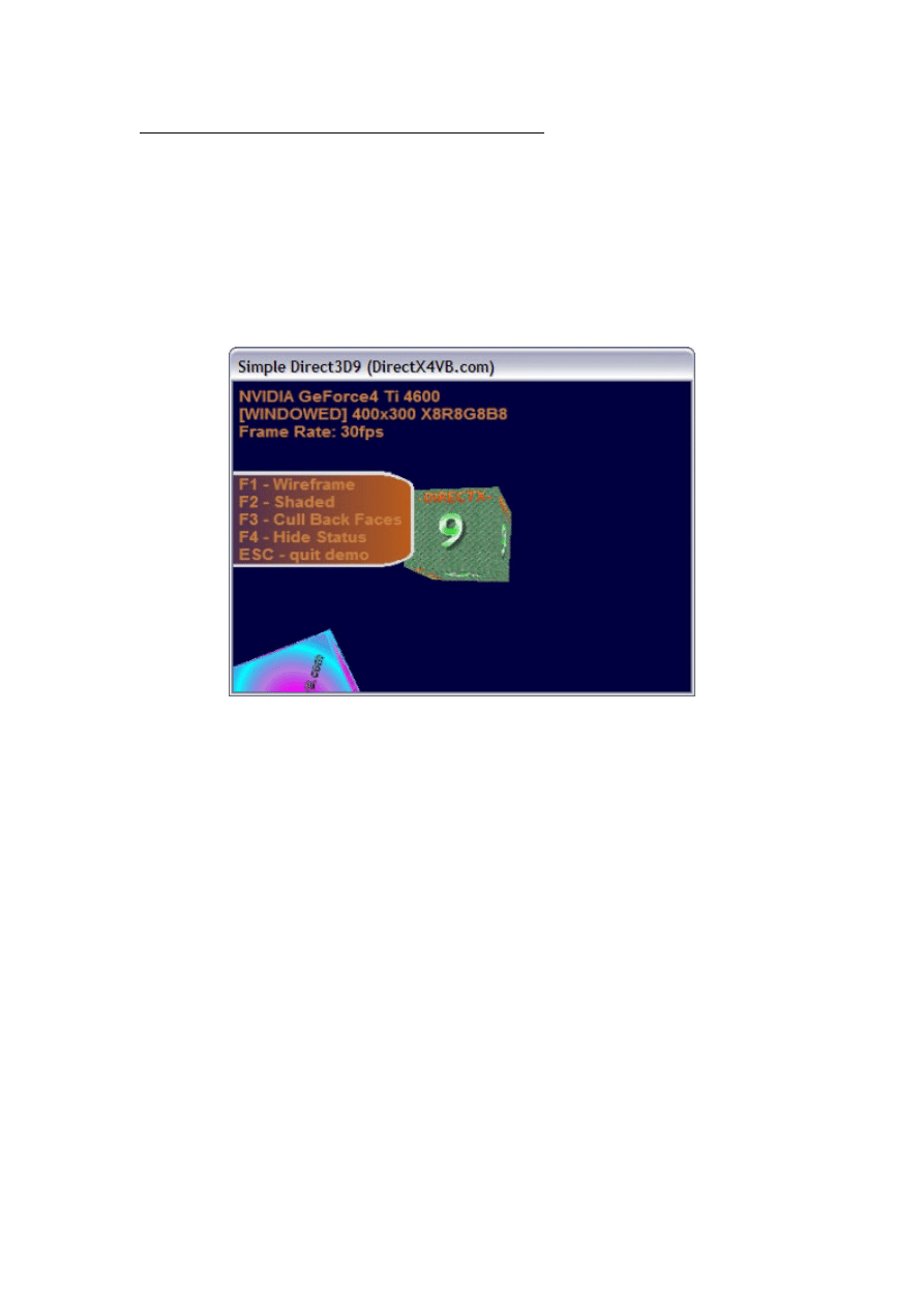
Introduction to Microsoft DirectX 9.0 (Managed Code)
written by Jack Hoxley ( Jack.Hoxley@DirectX4VB.com )
Completing the Engine: oneFrameRender()
Looking back to the original class definition we are left with only the
oneFrameRender() function to handle all our rendering. oneFrameUpdate() did
the necessary calculations, and now we just need to shift all the work over to the
D3D runtimes/drivers/hardware. Based on the previous section, this is the place
where you’d attempt early-rejection of invisible geometry and/or other
optimization algorithms.
For the sample code we have only 4 piece of rendering to do – the 3D objects, a
2D menu and some text. The final result will look something like this:
The text is fairly obvious, the menu is the orange background with a white border
and the 3D geometry is the two cubes you can see. One of the first things to
notice in the image is the transparent area on the menu background. The right-
most corners are both curved; and the areas outside the white border are
transparent. This is shown up further by the fact you can see part of the green
cube where the texture would normally be.
Before I show you the full code it is necessary to appreciate the most basic 3D
rendering structure – the 4 D3D9 function calls that make up 99% of all
rendering functions used on this planet:
Public
Sub
oneFrameRender()
If
Not
bInitOkay
Then
Throw
_
New
Exception("…")
D3DDev.Clear(ClearFlags.Target
Or
ClearFlags.ZBuffer, _
Drawing.Color.FromArgb(255, 0, 0, 64), 1.0F, 0)
D3DDev.BeginScene()
D3DDev.EndScene()
D3DDev.Present()
End
Sub
The first line in the above framework just catches errors early – if the engine is
not initalised properly then almost every D3D call made in this function will fail –
so just to keep things simple: if the engine isn’t initialised then we don’t render.
- 45 -

Introduction to Microsoft DirectX 9.0 (Managed Code)
written by Jack Hoxley ( Jack.Hoxley@DirectX4VB.com )
The second line, D3DDev.Clear(…), sets up the render target for us – clearing
what was rendered in the last frame (although, it is likely to have been
corrupted) and resets the depth buffer. You can achieve some interesting effects
by altering this line (try removing Target or ZBuffer and see what happens) but in
general you want to start each frame with a fresh canvas to work with. The first
parameter tells D3D what parts of the rendering system you want cleared –
Target, ZBuffer or Stencil. We’re not using a stencil buffer so don’t try to use that
flag. The target refers to the color buffer (where the final image is stored) and
the ZBuffer is the depth buffer. The second parameter indicates what color you
want the target to be cleared to – this is the color that you’ll see in any pixel that
you haven’t rendered over with geometry of some kind. In this example it’s a
dark blue color (alpha must be 255). The third parameter is the value to clear the
ZBuffer to (you don’t store any color information in the ZBuffer), this will always
be a value in the range 0.0 to 1.0, and you will rarely need to use anything but
1.0F. The last parameter is the stencil clear value; we’re not using stencil buffers
so we can leave this as 0.
The third and fourth lines make a matching pair – you have to begin the scene (a
scene is a single frame) and end it. All rendering (2D or 3D) should be done
within this pair of lines. For more advanced tricks it is possible to use multiple
begin/end scene calls, but you won’t need to use this.
The final line, Present(), appears to be a very simple function call – but is
incredibly important; without it you wont see anything on the screen. This
function takes the image you’ve been rendering from the back buffer and displays
it on the screen (as the front buffer) and then frees up the back buffer for you to
use on the next frame. Direct3D doesn’t actually copy the image that you’ve
rendered (that would be to slow), instead it cycles a set of pointers around –
effectively swapping the back-buffer and front-buffer over.
Back to the actual code that we’ll be using in the sample…
Because of the draw-order issues regarding transparent textures we’ll be
rendering the two cubes first, then the menu bar and then the text. This draw
order guarantees that everything will appear correctly on screen.
D3DDev.SetStreamSource(0, vbCube, 0)
D3DDev.VertexFormat = CustomVertex.PositionTextured.Format
The above two lines will configure the device to use the vertex data for the cube.
Both cubes work with the same original geometry such that this pair of lines
needs only be executed once. The first line just tells Direct3D where to find the
vertex data and the second line tells Direct3D what format the data will be in
(and what data each vertex contains).
If
bRenderTextures
Then
D3DDev.SetTexture(0, texCube1)
Else
D3DDev.SetTexture(0,
Nothing
)
End
If
D3DDev.Transform.World = matCube1
D3DDev.DrawPrimitives(PrimitiveType.TriangleList, 0, 12)
This next set of lines actually renders the first cube. Once these lines are
complete the cube will be drawn on the back buffer. The first conditional is just
for the sample – pressing F2 will allow you to toggle textures on/off. The next
part applies the transformation matrix to the device, telling Direct3D that all
incoming vertex data should be transformed by matCube1. The last line actually
renders the data, the first parameter is necessary to tell D3D how the vertices are
- 46 -

Introduction to Microsoft DirectX 9.0 (Managed Code)
written by Jack Hoxley ( Jack.Hoxley@DirectX4VB.com )
organised (see the geometry rendering section) and the second and third
parameters tell D3D which part of the vertex buffer we want rendered. In our
case we’re rendering a list of 12 triangles starting at the first vertex in the
stream. The second cube is rendered in an identical fashion, except it uses
texCube2 and matCube2.
Dim
bPrev
As
Boolean
= wireframe()
wireframe =
False
D3DDev.RenderState.AlphaBlendEnable =
True
D3DDev.SetStreamSource(0, vbMenu, 0)
D3DDev.VertexFormat = CustomVertex.TransformedTextured.Format
D3DDev.SetTexture(0, texMenu)
D3DDev.DrawPrimitives(PrimitiveType.TriangleStrip, 0, 2)
D3DDev.RenderState.AlphaBlendEnable =
False
wireframe = bPrev
This next part renders the 2D menu. It’s very similar to the previous code, but
with a couple of subtle differences.
Firstly, we disable wire-frame rendering, it is possible for the user to toggle
solid/wireframe rendering, but we only want this to apply to the 3D geometry.
However, to guarantee correctly operation we have to cache the previous
wireframe status (on/off) before changing it.
Secondly, we enable alpha blending – this tells Direct3D to use the color key
operations configured in initialiseDevice() and specified in loadTextures().
The net result is that all magenta colored pixels will not be rendered.
At this point we have finished rendering all the geometry. Take time to notice
that whilst they give very different results on-screen they are not very different
when written in code. You must tell D3D where the geometry is located, you must
tell it what format you’re using, and you have to set the texture (if you’re using
textures that is).
The last part of oneFrameRender() that we need to look at is text rendering. Text
is an often-required part of graphics applications but the method we’re using (and
that built into D3D) is not particularly efficient. For the amount of text shown in
the sample code it wont matter – but for a game that relies heavily on displaying
large amounts of text you can find it chokes. A custom text rendering system is
often far more efficient (you can fine tune it to do only the things you want it to).
fntOut.DrawText("Frame Rate: " + iFrameRate.ToString + "fps", _
New
Drawing.Rectangle(5, 5 + (2 * (iFontSize + 6)), 0, 0), _
DrawTextFormat.Left
Or
DrawTextFormat.Top, _
Drawing.Color.FromArgb(255, 200, 128, 64))
The above code is reasonably simple and powerful. You specify the text to be
rendered and the rectangle you want it rendered to (note, it will be clipped), the
text drawing operations (e.g. Left/center/right aligned) and the color. The only
complicated part is determining the size of the rectangle to use; trial-and-error is
often sufficient – but as a rule of thumb take the font size and add 2 for the
height. It might seem simpler to specify the whole screen as the rectangle (or a
very large area) but this works out to be quite inefficient (it has implications
further down the D3D runtime when it draws the text).
- 47 -

Introduction to Microsoft DirectX 9.0 (Managed Code)
written by Jack Hoxley ( Jack.Hoxley@DirectX4VB.com )
Using The Engine
We’ve now completed the engine. If it has been designed correctly we can now
use it – and hopefully use it without any detailed knowledge of how it works. It
would require a little more work, but we should be able to store
CSampleGraphicsEngine in it’s own library and import it into any project wanting
to use its features.
Linking the Class to the Form
We must link the engine to a control system and we must link Direct3D to a
windows form. The control system is necessary to keep the main loop executing
and to allow the user to specify options (such as those presented with the F1-F4
keys in this sample program), and Direct3D needs a form (or picture) object to fit
its rendered images into.
Because Direct3D handles all of the graphics for our sample we don’t need our
windows form to do anything special – it needs only “sit” there and act as a
container for our graphics engine. In windowed mode it is possible to add other
(normal) windows controls into the application like normal; however this isn’t
going to work properly when you switch to fullscreen. Unless you really need to,
try not to mix windows controls and Direct3D together too much – it is possible,
but it’s slightly tricky (the SDK contains a sample on how to do this).
For this sample I used the default form created by VisualStudio.Net when you add
a form to the project; I changed the settings such that you can’t
minimize/maximize/resize the window and left everything else alone. The rest is
all done using code.
Private
c3DEngine
As
CSampleGraphicsEngine
Private
bRunning
As
Boolea
False
n
=
#
Const
RENDER_WINDOWED = 1
I added a conditional compilation option to switch between windowed and
fullscreen initialisation; it would have been fairly easy to allow the user to specify
each time they started the application. Because of this, initialisation of the class
varies depending on which value the RENDER_WINDOWED constant has.
c3DEngine =
New
CSampleGraphicsEngine(
Me
)
Above is the simple windowed mode intialisation. The 2
nd
line is the only one that
actually does anything – the rest are error handling.
- 48 -

Introduction to Microsoft DirectX 9.0 (Managed Code)
written by Jack Hoxley ( Jack.Hoxley@DirectX4VB.com )
The next piece of code handles fullscreen initialisation; it makes particular use of
the shared function isDisplayModeOkay() defined in the
CSampleGraphicsEngine class.
dim
iW
as
Integer
= 0, iH
as
Integer
= 0, iD
as
Integer
= 0
If
CSampleGraphicsEngine.isDisplayModeOkay(1024, 768, 32)
Then
iW = 1024 : iH = 768 : iD = 32
ElseIf
(CSampleGraphicsEngine.isDisplayModeOkay(1024, 768, 16))
Then
iW = 1024 : iH = 768 : iD = 16
ElseIf
(CSampleGraphicsEngine.isDisplayModeOkay(640, 480, 32))
Then
iW = 640 : iH = 480 : iD = 32
ElseIf
(CSampleGraphicsEngine.isDisplayModeOkay(640, 480, 16))
Then
iW = 640 : iH = 480 : iD = 16
Else
'no modes supported?!
Throw
New
Exception("No supported display modes found")
End
If
c3DEngine =
New
CSampleGraphicsEngine(
Me
, iW, iH, iD)
The sample only attempts 2 resolutions at the two commonly supported display
modes, a real application would allow the user to select any of the supported
resolutions at any of the supported depths. I only implemented it this way for
simplicity.
We don’t actually need error checking around the graphics engine initialisation
calls – the whole of the procedure is wrapped in a try…catch block such that they
will pick up (and dispose of) the error.
Once we’ve created a valid reference to the CSampleGraphicsEngine class we
can go about configuring it. This is where we access the public properties we
created earlier to control how the 3D engine will work.
'set the initial properties for the engine
c3DEngine.backFaceCulling =
False
c3DEngine.drawFrameRate =
True
c3DEngine.useTextures =
True
c3DEngine.wireframe =
False
bRunning =
True
All fairly simple really – the initial properties set above will yield what you’d
expect to see from a 3D graphics engine.
The next part is the interesting part – the main application loop. High
performance multimedia applications generally work by bolting through all
relevant code as fast as is possible on the current hardware. In this sample we
only have to worry about graphics, such that as soon as we finish one frame we
start on the next frame. This is effectively an extremely tight loop:
Do
While
bRunning
'these two functions do all the work,
c3DEngine.oneFrameUpdate()
c3DEngine.oneFrameRender()
Application.DoEvents()
Loop
It is necessary to include the DoEvents() call – this allows the operating system
time to breathe and do any maintenance jobs; without it the application can run
faster but it wont process user input properly and can lead to an unstable system.
The loop will loop infinitely until the bRunning variable becomes false, we use this
flag to control termination – class destructors and the .Net framework will
- 49 -

Introduction to Microsoft DirectX 9.0 (Managed Code)
written by Jack Hoxley ( Jack.Hoxley@DirectX4VB.com )
generally clean up if we allow the user to click on the close button, but it removes
any control that we have over correctly unloading data.
The code mentioned thus far is all we need to get the graphics engine up and
running, however there are a few loose ends left to tie up. User input is still not
handled – we need to allow the user to press buttons and get results.
We can use the .Net frameworks built in keyboard handling functions for the
windows form object to do this job:
Protected Overrides Sub
OnKeyDown(
ByVal
e
As
System.Windows.Forms.KeyEventArgs)
Select Case
e.KeyCode
Case
Keys.Escape
bRunning =
False
Case
Keys.F1
c3DEngine.wireframe =
Not
c3DEngine.wireframe
Case
Keys.F2
c3DEngine.useTextures =
Not
c3DEngine.useTextures
Case
Keys.F3
c3DEngine.backFaceCulling =
Not
c3DEngine.backFaceCulling
Case
Keys.F4
c3DEngine.drawFrameRate =
Not
c3DEngine.drawFrameRate
End Select
End Sub
With all this code in place, we have a complete and working Direct3D9 sample
application!
- 50 -

Introduction to Microsoft DirectX 9.0 (Managed Code)
written by Jack Hoxley ( Jack.Hoxley@DirectX4VB.com )
Conclusion
Now that we’ve covered all the code and theory for this tutorial the only thing left
is to conclude…
What you Should Have Learnt
In this tutorial you should have become familiar with:
1. basic 3D theory; how a scene is built up (vertices, triangles etc…) and
most of the keywords associated with this field.
2. How Direct3D9 works and how it integrates with your system (drivers,
hardware, OS configuration etc…)
3. How to set up a simple Direct3D9 interface ready for you to work with.
4. How to create geometry manually
5. How to load textures of varying configurations
6. How to set up a simple matrix transformation for 3D geometry and learnt
the associated rules.
7. learnt the rules and theory of rendering geometry to the screen (in
particular draw order and invisible geometry)
Hopefully the way that I divided this tutorial up allows you to isolate individual
parts and re-read them if necessary.
What to do Next
Bare in mind that from the outset this tutorial could not (and did not intend to)
teach you everything about Direct3D9 managed code. If this is your first taster of
D3D then you’re only a few steps down an extremely long path – there is a lot
more to learn yet.
The next step is to make your own version of this tutorial code. Use my class
outline as a template and try something a little more complicated; try creating a
simple 3D world using simple 3D geometry.
However, the next step is not to start work on your own “simple quake-like
game”. I can’t stress how many emails I get from people who’ve only just started
with D3D and want to work on commercial-level projects. It isn’t going to happen
that quickly. The only way it will happen is if you’re a veteran of a previous
graphics-programming library (Direct3D, OpenGL, Glide or software).
Once you’re familiar with the basics – branch out a bit; try something a little
more complicated (a full, yet simple game). You need only try something a little
more adventurous to add a huge number of new challenges. Real games require
mathematics, physics and algorithms – make sure you’re ready to meet their
demands as and when they crop up.
- 51 -

Introduction to Microsoft DirectX 9.0 (Managed Code)
written by Jack Hoxley ( Jack.Hoxley@DirectX4VB.com )
Other Resources to Look at
Your key resource is the Internet. Books are great but they’re quite expensive –
there are a few books (see the references section below) that are worth the
asking price, but they’re often for the more advanced programmers. The internet
has a great wealth of sites like mine that host tutorials for all types of developers
trying to do all types of things. Web forums and newsgroups are also a key
resource – finding a website that you can ask questions (and eventually answers
other peoples questions) and get a good response is often worth more than an
individual tutorial.
All told, I really hope you’ve enjoyed this tutorial. Feel free to drop me an email:
- I always like to hear from people who’ve made
good use of the tutorials I write.
- 52 -

Introduction to Microsoft DirectX 9.0 (Managed Code)
written by Jack Hoxley ( Jack.Hoxley@DirectX4VB.com )
About Me
My name, as you’ve probably guessed is Jack Hoxley – I’m currently studying for
my BSc. Computer Science degree at the University of Nottingham, England.
Whilst I do work hard for my degree I still find myself with a substantial amount
of spare time ☺ which, if not for sleeping/socializing/partying, is often spent
reading further into the two areas of computer programming that interest me:
Graphics and Artificial Intelligence.
For some years now I’ve been messing around with various types of graphics
engines and AI systems – seeing if I can/can’t implement certain types of
algorithms and generally experimenting to see what happens. For the last year
(at time of writing) I’ve been working with a team of dedicated Formula-1 racing
fanatics to create the ultimate F1 management simulation – F1CM. Hopefully
that’ll be in the stores sometime in 2003.
I’ve also (as mentioned earlier) been participating in the DirectX9 beta program
for the last 6 months, which has greatly advanced my knowledge of the API.
Acknowledgements
I’d like to mention the following people/groups of people and sources (in no
particular order):
The Microsoft DirectX Developers
The DirectX9 beta developers
The Visual Basic gaming community
Any other developers I’ve come across in my travels.
The visitors to my website
- 53 -

Introduction to Microsoft DirectX 9.0 (Managed Code)
written by Jack Hoxley ( Jack.Hoxley@DirectX4VB.com )
References
The following list contains a few of the books and sources I’ve found useful in
extending my knowledge of computer graphics.
Web resources
- high quality articles and a reasonable forum (if only they’d
ban anonymous posting!)
- good for news and the image-of-the-day gallery.
- best source for games-industry news and articles.
- a good site with a great forum for meeting
other VB multimedia programmers
- lucky’s ever-popular site, no recent content but
some great web forums.
- how could I not mention my own website yet again? ☺
Books
None of these books directly contributed to the tutorial text, I’ve included them
because they’ve proven to be useful to me on many occasions – they are my
favorite/recommended books. All of these have been reviewed by myself and can
be viewed here:
http://www.DirectX4VB.com/reviews.asp
Real-Time Rendering 2nd Edition
Tomas Akenine-Möller & Eric Haines
ISBN: 1-56881-182-9
Mathematics for 3D Game Programming & Computer Graphics
Eric Lengyel
ISBN: 1-58450-037-9
Visual Basic Game Programming with DirectX
Jonathon S. Harbour
ISBN: 1-931841-25-X
Real-Time Rendering Tricks and Techniques in DirectX
Kelly Dempski
ISBN: 1-931841-27-6
Special Effects Game Programming with DirectX
Mason McCuskey
ISBN: 1-931841-06-3
- 54 -

Introduction to Microsoft DirectX 9.0 (Managed Code)
written by Jack Hoxley ( Jack.Hoxley@DirectX4VB.com )
Disclaimer
This tutorial was written entirely by me – including the source code. It’s draws
together some of the ideas I’ve highlighted in other tutorials on my site, but
where I’ve quoted from (or used) content from other sites I’ve mentioned it.
The bottom line is: I don’t get paid for this (or make any money), I do this in my
spare time (of which I don’t have a huge amount, this tutorial took me almost
20hrs to write), please don’t give me too much grief regarding little errors – I try
my best! Feel free to email me regarding any little bugs/mistakes, but I cant
guarantee I’ll get a chance to update the text. The source code was tested on as
many systems as possible and is known to work on compatible systems – this
doesn’t necessarily mean it’ll work on your system.
Distribution
I don’t mind if you distribute this pdf document or the source code, but they must
remain intact and I wish to retain full credit for the work contained within. If you
are going to host this document on your website/server please send me an email
– just so I can keep track of who has a copy…
©2003 Jack Hoxley – All Rights Reserved.
- 55 -

Introduction to Microsoft DirectX 9.0 (Managed Code)
written by Jack Hoxley ( Jack.Hoxley@DirectX4VB.com )
Revision and Latest Information
Version 1.0
Original document.
Version 1.1 (Monday 3
rd
February 2003)
Added additional supporting code in C# and C++ form. These are only provided
as-is, and aren’t actually part of the main tutorial text. The C++ version was
converted by myself, and the C# version was kindly donated by Joel Mueller. It is
advised that you view the projects in Visual Studio .Net 2002 but the C++
version should work under Visual C++ 6.0 with a little work.
- 56 -
Document Outline
- Introduction3
- What are 3D graphics, and where does Direct3D fit in?4
- Basic 3D theory5
- The Managed-code interfaces for Direct3D98
Wyszukiwarka
Podobne podstrony:
Direct3D 11 Tessellation
Premier Press Beginning DirectX 9
Active Directory
5. Prensa, Hiszpański, Kultura, España en directo
2009 11 17 arduino basics
Active Directory
LV Basics I (2)
Excel VBA Course Notes 1 Macro Basics
Direct3D Vertex shader 1
CATIA V5 Training Basics
Intermediate Short Stories with Questions, Driving Directions
Directional Movement Index, giełda(3)
directx
Komunikacja rynkowa direct response marketing
Aplikacje Direct3D
23 directionsforuse
więcej podobnych podstron