XT40.241, XT40.242
– X-Series
24V, 40A, T
HREE
-P
HASE
I
NPUT
Jan. 2007 / Rev. 1.0 DS-XT40.24x-EN All parameters are specified at 24V 40A, 3x400Vac (XT40.241) or 3x480Vac (XT40.242),
25°C ambient and after a 5 minutes run-in time unless otherwise noted.
www.pulspower.com Phone +49 89 9278 0 Germany
1/20
S
EMI
-R
EGULATED
P
OWER
S
UPPLY
•
Alternative or Replacement for AC Transformer
•
Three Phase Input – DC Output
•
DIN-Rail Mountable
•
Width only 96mm
•
95.5% Efficiency
•
125% Peak Power Capability
•
No Input Inrush Current
•
Active Input Transient Blocker
•
Full Power Between -25°C and +60°C
•
Easy Failure Diagnostics
•
No Electrolytic Capacitors on Input Side
•
Cost Effective and Robust
•
3 Year Warranty
1. G
ENERAL
D
ESCRIPTION
2. S
HORT
-
FORM
D
ATA
Output voltage
DC 24V
Factory setting to
24.1V
Adjustment range
none
Output current
40A
continuous
50A
for typ. 15s
Output power
960W
continuous
1200W
for typ. 15s
Output ripple
< 1500mVpp
20Hz-2kHz
< 200mVpp
2kHz to 20MHz
Input voltage
3AC 400V
XT40.241
3AC
480V
XT40.242
Mains frequency
50-60Hz
±6%
AC Input current
1.65A / phase
XT40.241, 3x400V
1.4A / phase
XT40.242, 3x480V
Power factor
0.93
24V, 40A
AC Inrush current
typ. 2A peak
Efficiency 95.5%
Losses 45.2W
Temperature range -25°C to +70°C
operational
Derating
24W/°C
+60 to +70°C
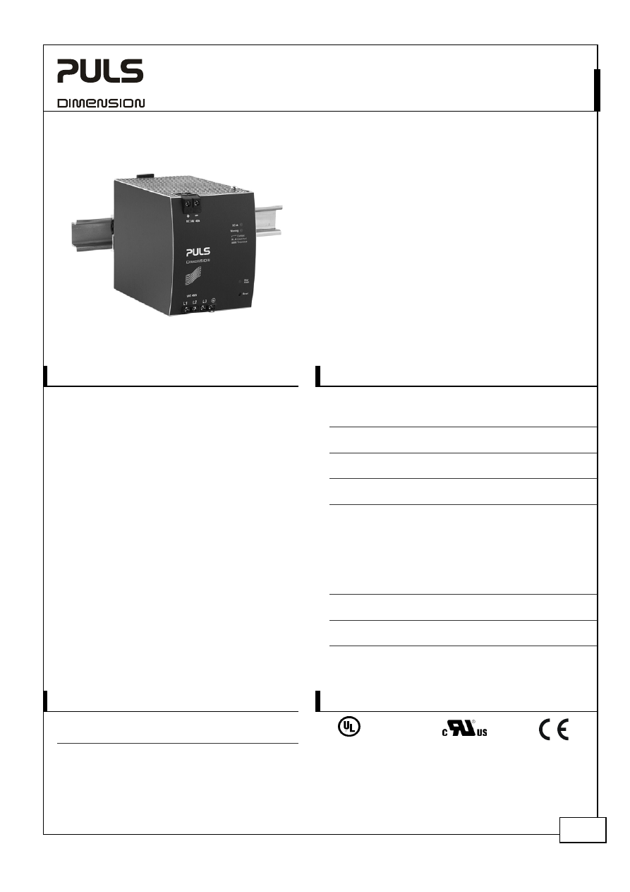
The power supplies in the Dimension X-Series include
a new and innovative concept for generating an
isolated DC voltage from a three-phase mains
system.
A semi-regulated resonant converter enables a very
compact design, maximum efficiency and extremely
competitive pricing with only a small compromise in
the output voltage regulation, output ripple and
hold-up time.
Weighing just 1.4 kg, the device provides 960 watts
of continuous output power and an additional 25%
power reserve for dynamic loads. The light-weight
design along with compact dimensions facilitate
straightforward mounting on DIN-rail.
Primary use are applications involving supplies to
motors, valves and other load circuits with a high
power consumption, where an accurate output
voltage regulation which is standard on traditional
switched-mode power supplies is not required.
Furthermore, these switched-mode power supplies
can often replace mains transformers with rectifiers.
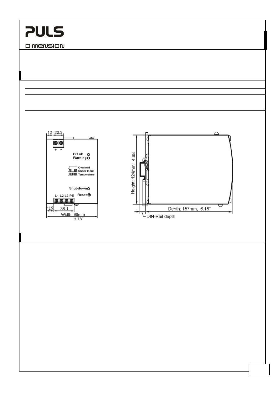
Dimensions 96x124x159mm
WxHxD
3. O
RDER
N
UMBERS
4. M
ARKINGS
Power
Supply XT40.241
400V Input
XT40.242
480V Input
IND. CONT. EQ.
18WM
LISTED
UL 508
UL 60950-1
EMC, LVD
Accessory UF20.241
SLR01
24V Buffer Unit
Redundancy Module
XT40.241, XT40.242
– X-Series
24V, 40A, T
HREE
-P
HASE
I
NPUT
Jan. 2007 / Rev. 1.0 DS-XT40.24x-EN All parameters are specified at 24V 40A, 3x400Vac (XT40.241) or 3x480Vac (XT40.242),
25°C ambient and after a 5 minutes run-in time unless otherwise noted.
www.pulspower.com Phone +49 89 9278 0 Germany
2/20
I
NDEX
P
AGE
I
NDEX
P
AGE
1.
General Description ............................................1
2.
Short-form Data ..................................................1
3.
Order Numbers....................................................1
4.
Markings ..............................................................1
5.
AC-Input...............................................................3
6.
Input Inrush Current ...........................................4
7.
Output .................................................................5
8.
Hold-up Time.......................................................6
9.
Efficiency and Power Losses................................7
10.
Functional Diagram.............................................8
11.
Front Side and User Elements.............................8
12.
Terminals and Wiring..........................................9
13.
Reliability .............................................................9
14.
EMC....................................................................10
15.
Environment ......................................................11
16.
Protection Features ...........................................12
17.
Safety .................................................................12
18.
Dielectric Strength ............................................12
19.
Approvals...........................................................13
20.
Fulfilled Standards ............................................13
21.
Used Substances ............................................... 13
22.
Physical Dimensions and Weight ..................... 14
23.
Installation and Operation Instructions .......... 14
24.
Accessories ........................................................ 15
25.
Comparison between the XT40, a Transformer
and a Traditional Switched-mode Power Supply .. 15
26.
Application Notes............................................. 16
26.1.
Periodical Peak Power Capability .......... 16
26.2.
Charging of Batteries ............................. 16
26.3.
Output Circuit Breakers ......................... 17
26.4.
External Input Protection....................... 18
26.5.
Back-feeding Loads ................................ 18
26.6.
Parallel Use to Increase Output Power . 18
26.7.
Parallel Use for Redundancy.................. 18
26.8.
Series Operation..................................... 19
26.9.
Inductive and Capacitive Loads ............. 19
26.10.
Loss of One Input Phase......................... 19
26.11.
Use in a Tightly Sealed Enclosure .......... 19
26.12.
Mounting Orientations .......................... 20
I
NTENDED
U
SE
The power supply shall only be installed and put into operation by qualified personnel.
This power supply is designed for installation in an enclosure and is intended for the general use, such as in industrial
control, office, communication, and instrumentation equipment. Do not use this device in aircraft, trains and nuclear
equipment, where malfunctioning of the power supply may cause severe personal injury or threaten human life.
T
ERMINOLOGY AND
A
BREVIATIONS
PE and
symbol
PE is the abbreviation for Protective Earth and has the same meaning as the symbol
.
Earth, Ground
This document uses the term “earth” which is the same as the U.S. term “ground”.
T.b.d.
To be defined, value or description will follow later.
3AC 400V
A figure displayed with the AC or DC before the value represents a nominal voltage with
standard tolerances (usually ±15%) included. 3AC means three phase input.
E.g.: DC 12V describes a 12V battery disregarding whether it is charged (13.7V) or
discharged (10V)
As long as otherwise stated, 3AC 400V parameters are valid at 50Hz and 3AC 480V
parameters are valid at 60Hz mains frequency.
3x 400Vac
A figure with the unit (Vac) at the end is a value which is used during testing without any
additional tolerances included. 3x 400Vac means a three phase input.
D
ISCLAIMER
The information presented in this document is believed to be accurate and reliable and may change without notice.
XT40.241, XT40.242
– X-Series
24V, 40A, T
HREE
-P
HASE
I
NPUT
Jan. 2007 / Rev. 1.0 DS-XT40.24x-EN All parameters are specified at 24V 40A, 3x400Vac (XT40.241) or 3x480Vac (XT40.242),
25°C ambient and after a 5 minutes run-in time unless otherwise noted.
www.pulspower.com Phone +49 89 9278 0 Germany
3/20
5. AC-I
NPUT
XT40.241 XT40.242
AC
input
nom.
3AC 400V
3AC 480V
Mains
arrangement
TN-, TT- or IT-Mains
consult factory if one phase is earthed
AC input range
min.
3x 360-440Vac 3x 432-528Vac fully regulated output (±2%), Pout > 48W
min.
3x 300-460Vac
*)
3x 360-552Vac
*)
permanently allowed,
see
Fig. 5-1
for output voltage regulation
max.
3x 475Vac
3x 565Vac
Absolute maximum input voltage with no
damage to the power supply. Output
might be off at this level.
Input
frequency
nom.
50 – 60Hz
50 – 60Hz
±6%
Turn-on
voltage
typ.
3x 325Vac
3x 390Vac
see
Fig. 5-2
Shut-down
voltage
typ.
3x 295Vac
3x 355Vac
see
Fig. 5-2
Input
current
nom.
1.65A
1.4A
at 40A, symmetrical input, see
Fig. 5-4
Power
factor
**)
typ.
0.93
0.93
at 40A, symmetrical input, see
Fig. 5-5
Turn-on
overshoot
typ.
480mV 480mV
see
Fig. 5-3
Start-up delay ***)
typ.
400ms
350ms
over the entire load range, see
Fig. 5-3
Rise
time
typ.
40ms
40ms
0mF, 40A, see
Fig. 5-3
typ.
70ms
70ms
40mF, 40A, see
Fig. 5-3
*)
A minimum voltage of 3x340Vac (XT40.241) or 3x408Vac (XT40.242) is required to turn the power supply on.
**)
The power factor is the ratio of the true (or real) power to the apparent power in an AC circuit.
***)
The start-up delay for mains voltage interruptions up to 350ms is close to zero. In such cases, the power supply will
immediately generate the output voltage once the mains voltage interruption is over. Do not use the buffer module
UF20.241 as an accessory when longer mains interruptions need to be bridged (see chapter 24).
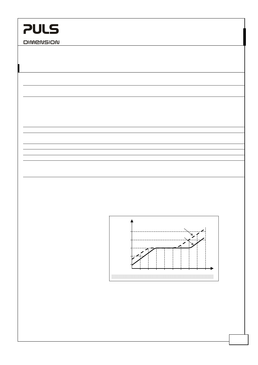
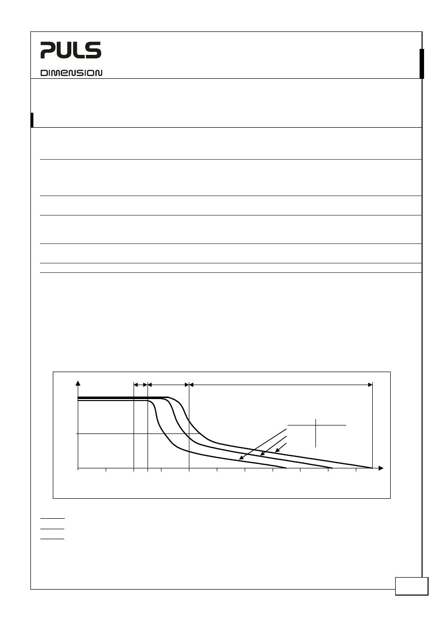
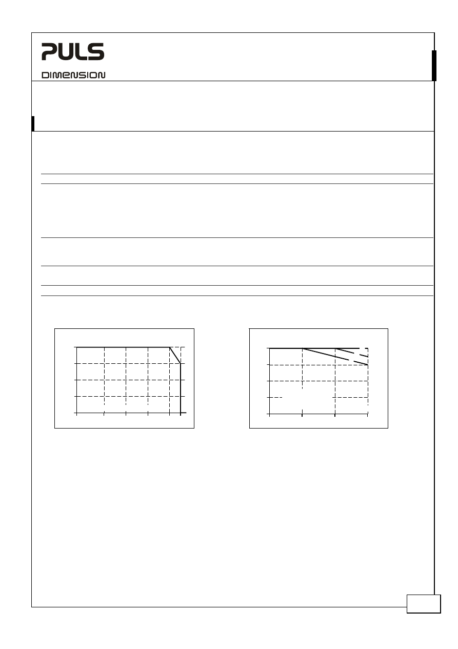
Input Voltage Range
Fig. 5-1 Output voltage vs. input voltage and input current
Changes of the input voltage will be fully
regulated within certain limits. The
output voltage will only start to change
proportionally to the input voltage with
extreme under or over-voltages. The
yellow LED reports an input voltage
problem if exceeded by a window of
±15%. The maximum increase of the
output voltage is limited to the 29.9V
OVP level. This level will be kept
regulated for 2s before the power supply
will shut down and reports “Shut-down”
by the red LED.
24V
20V
26V
22V
420
340
480Vac
320
504
456
576Vac
384
XT40.241:
V
OUT
V
IN
XT40.242:
400
360 380
440
480
460
300
28V
528 552
432
408
360
P
OUT
> 48W (5%)
P
OUT
= 0W
XT40.241, XT40.242
– X-Series
24V, 40A, T
HREE
-P
HASE
I
NPUT
Jan. 2007 / Rev. 1.0 DS-XT40.24x-EN All parameters are specified at 24V 40A, 3x400Vac (XT40.241) or 3x480Vac (XT40.242),
25°C ambient and after a 5 minutes run-in time unless otherwise noted.
www.pulspower.com Phone +49 89 9278 0 Germany
4/20
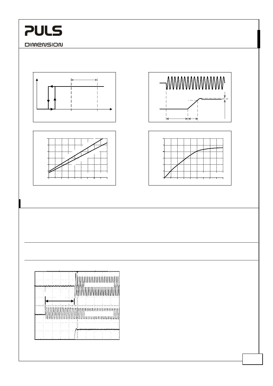
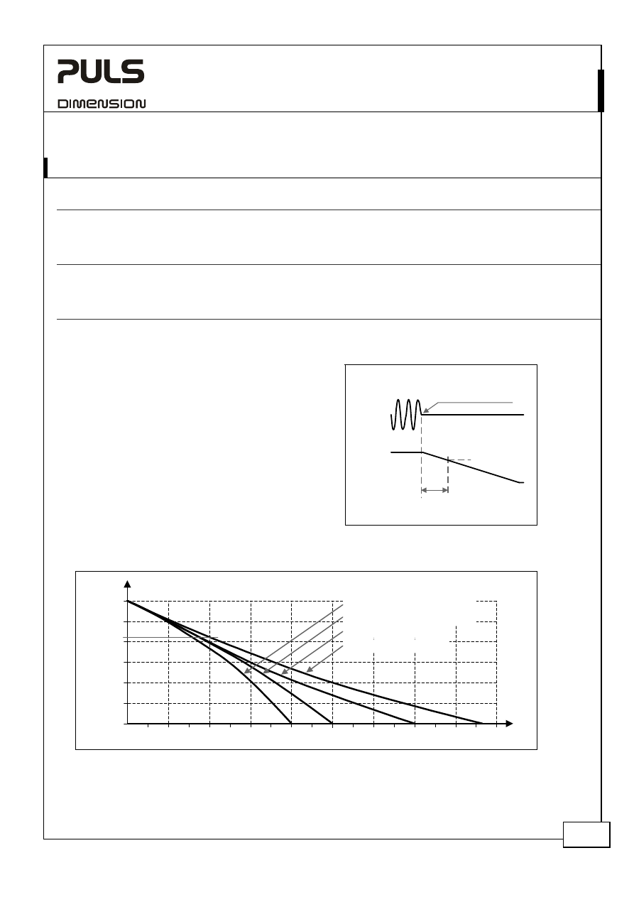
Fig. 5-2 Input voltage range
Fig. 5-3 Turn-on behavior definitions
Tur
n
-on
fully regulated
range
V
IN
P
OUT
3x 528Vac
S
hut
-down
3x 432Vac
480V Version:
3x 440Vac
3x 360Vac
400V Version:
Start-up
delay
Rise
Time
Ov
ershoot
- 5%
Output
Voltage
Intput
Voltage
Fig. 5-4 Input current vs. output load
Fig. 5-5 Power factor vs. output load
50A
5 10
30
45
0
0.3
0.6
0.9
1.2
1.5
1.8A
Input Current per Phase, typ.
Output Current
15 20 25
35 40
XT
40
.24
1 (
3x
40
0V
)
XT
40
.24
2 (
3x
48
0V
)
50A
5 10
30
45
0.70
0.75
0.8
0.85
0.9
0.95
1.0
Power Factor, typ.
Output Current
15 20 25
35 40
6. I
NPUT
I
NRUSH
C
URRENT
There is virtually no input inrush current surge as there are no electrolytic bulk-capacitors utilized on the input side of
the power supply.
The charging current into the EMI suppression capacitors is disregarded for the first millisecond after switch-on.
XT40.241 XT40.242
Inrush
current
max.
4A
peak
4A
peak
-25°C to +70°C, see
Fig. 6-1
Inrush
energy
max.
5A
2
s 5A
2
s
-25°C to +70°C, see
Fig. 6-1
Inrush
delay
typ.
400ms 350ms
see
Fig. 6-1
Fig. 6-1 Input inrush current, typical behavior
Input Current
Input Voltage
Output Voltage
A
A:
Inrush
delay
XT40.241:
Input:
3x400Vac, only one phase shown
Output:
24V, 40A
Ambient: 25°C
Upper curve:
Input current 2A / DIV
Medium curve: Input voltage 500V / DIV
(measured between L and N)
Lower curve:
Output voltage 20V / DIV
Time basis:
100ms / DIV
XT40.241, XT40.242
– X-Series
24V, 40A, T
HREE
-P
HASE
I
NPUT
Jan. 2007 / Rev. 1.0 DS-XT40.24x-EN All parameters are specified at 24V 40A, 3x400Vac (XT40.241) or 3x480Vac (XT40.242),
25°C ambient and after a 5 minutes run-in time unless otherwise noted.
www.pulspower.com Phone +49 89 9278 0 Germany
5/20
7. O
UTPUT
Output
voltage
nom.
24.1V
Output voltage adjustment range
none
The output voltage is fixed. No adjustment possible
Output current
nom.
40A continuous,
see
Fig. 7-1
50A
up to 15s with full output voltage, see
Fig. 7-1
Short-circuit current
typ.
180A
load impedance 25mOhm, see
Fig. 7-1
Note: The short-circuit current is available for 0.1s
Output
power
nom.
960W continuous
1200W
up to 15s
Line
regulation
max.
±2% see
Fig. 5-1
Load
regulation
max.
800mV
static value, 0A Æ 40A Æ 0A
max.
200mV
static value, 5A Æ 40A Æ 5A
Ripple and noise voltage *)
max.
1500mVpp 20Hz-2kHz,
50Ohm
max.
50mVpp
2kHz to 20MHz, 50Ohm
Output
capacitance
typ.
20 000µF
*) The ripple and noise voltage mostly consist of a mains ripple with 300Hz (50Hz mains) or 360Hz (60Hz mains). The ripple and
noise voltage can be reduced by the utilization of external capacitors.
The power supply is also designed to support loads with a higher short-term current and power requirement. The
short-term duration is firmware controlled by an output power manager. If the nominal output power is exceeded for
a certain period of time which is defined in the zone A, B and C, the power supply responds with an automatic shut-
down. Pressing the reset button or cycling the input power (10s off time is required) initiates an attempt to restart. If
the fault has been cleared the device will operate normally.
The short term power can be used periodically. See chapter 26.1 for further information.
Fig. 7-1 Output voltage vs. output current, typ.
V
OUT
40A 50A
140A
80A
0
A
15s
24V
200A
60A
20A
100A
120A
160A
180A
12V
I
OUT
B
5s
C
0.1s
3x 340V 3x 408V
3x 400V 3x 480V
3x 460V 3x 552V
XT40.241 XT40.242
Zone A: 25% extra output power for typ. 15s
Zone B: 100% higher output current for typ. 5s
Zone C: Quick-acting shut-down after typ. 0.1s
XT40.241, XT40.242
– X-Series
24V, 40A, T
HREE
-P
HASE
I
NPUT
Jan. 2007 / Rev. 1.0 DS-XT40.24x-EN All parameters are specified at 24V 40A, 3x400Vac (XT40.241) or 3x480Vac (XT40.242),
25°C ambient and after a 5 minutes run-in time unless otherwise noted.
www.pulspower.com Phone +49 89 9278 0 Germany
6/20
8. H
OLD
-
UP
T
IME
XT40.241 XT40.242
Hold-up
Time
typ.
2.0ms
2.0ms
40A, resistive load, see
Fig. 8-2
typ.
1.8ms
1.8ms
40A, constant power load, see
Fig. 8-2
typ.
4.0ms
4.0ms
20A, resistive load
typ.
3.6ms
3.6ms
20A, constant power load
Hold-up
Time
min.
1.6ms
1.6ms
40A, resistive load, see
Fig. 8-2
min.
1.45ms
1.45ms
40A, constant power load, see
Fig. 8-2
min.
3.2ms
3.2ms
20A, resistive load
min.
2.9ms
2.9ms
20A, constant power load
Fig. 8-1 Hold-up time, definitions
The energy is stored in the output capacitor. As
soon as the input is turned off, the output
capacitor will be discharged and the voltage will
dissipate according to the curves in
Fig. 8-2
. The
lighter the load, the longer the hold-up time. Half
the load means twice the hold-up time.
The hold-up time depends on the load
characteristic. The curves below show the hold-up
time for a load with a resistive and a constant
power characteristic.
The hold-up time is defined as the period of time
when the input is turned off and until the output
voltage falls below 24V
–15%
(20.4V). This value is
defined in the IEC61131-2 as the lower limit for the
supplying voltage.
-15%
Hold-
up
Time
Zero Transition
Output
Voltage
Intput
Voltage
Fig. 8-2 Hold-up time vs. input voltage
24V
12V
18V
14V
V
OUT
22V
16V
0.5 1.0 1.5 2.0 2.5 3.0 3.5 4.0 4.5
5.5 6.0 6.5 7.0 7.5 8.0
5.0
8.5 9.0ms
40A, constant power load, typ.
40A, resistive load, typ.
T
40A, constant power load, min.
40A, resistive load, min.
20.4V
Note: At no load, the hold-up time can be up to one minute. The green DC-ok LED is on during this time.
XT40.241, XT40.242
– X-Series
24V, 40A, T
HREE
-P
HASE
I
NPUT
Jan. 2007 / Rev. 1.0 DS-XT40.24x-EN All parameters are specified at 24V 40A, 3x400Vac (XT40.241) or 3x480Vac (XT40.242),
25°C ambient and after a 5 minutes run-in time unless otherwise noted.
www.pulspower.com Phone +49 89 9278 0 Germany
7/20
9. E
FFICIENCY AND
P
OWER
L
OSSES
XT40.241 XT40.242
Efficiency
typ.
95.5%
95.5%
40A
Power
losses
typ.
45.2W
45.2W
40A
typ.
18.2W
18.2W
0A
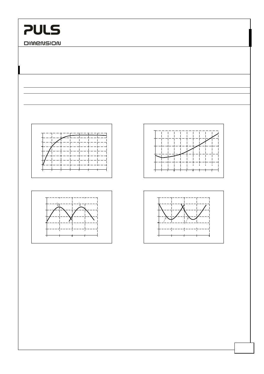
Fig. 9-1 Efficiency vs. output current
Fig. 9-2 Losses vs. output current
Efficiency
5
10
40A
88
89
90
91
92
93
Output Current
94
95
96%
15
20
25
30
35
Power Losses
0
4
8 12 16 20 24 28
40A
0
10
20
30
40
50W
32 36
Output Current
Fig. 9-3 Efficiency vs. input voltage, 24V, 40A
Fig. 9-4 Losses vs. input voltage, 24V, 40A
Efficiency
350
400
450
500 3x550
Vac
94.6
94.8
95.0
95.2
Input Voltage
95.4
95.6
95.8%
XT40.241
XT40.242
Power Losses
350
400
450
500 3x550
Vac
40
42
44
46
Input Voltage
48
50
52W
XT40.241
XT40.242
XT40.241, XT40.242
– X-Series
24V, 40A, T
HREE
-P
HASE
I
NPUT
Jan. 2007 / Rev. 1.0 DS-XT40.24x-EN All parameters are specified at 24V 40A, 3x400Vac (XT40.241) or 3x480Vac (XT40.242),
25°C ambient and after a 5 minutes run-in time unless otherwise noted.
www.pulspower.com Phone +49 89 9278 0 Germany
8/20
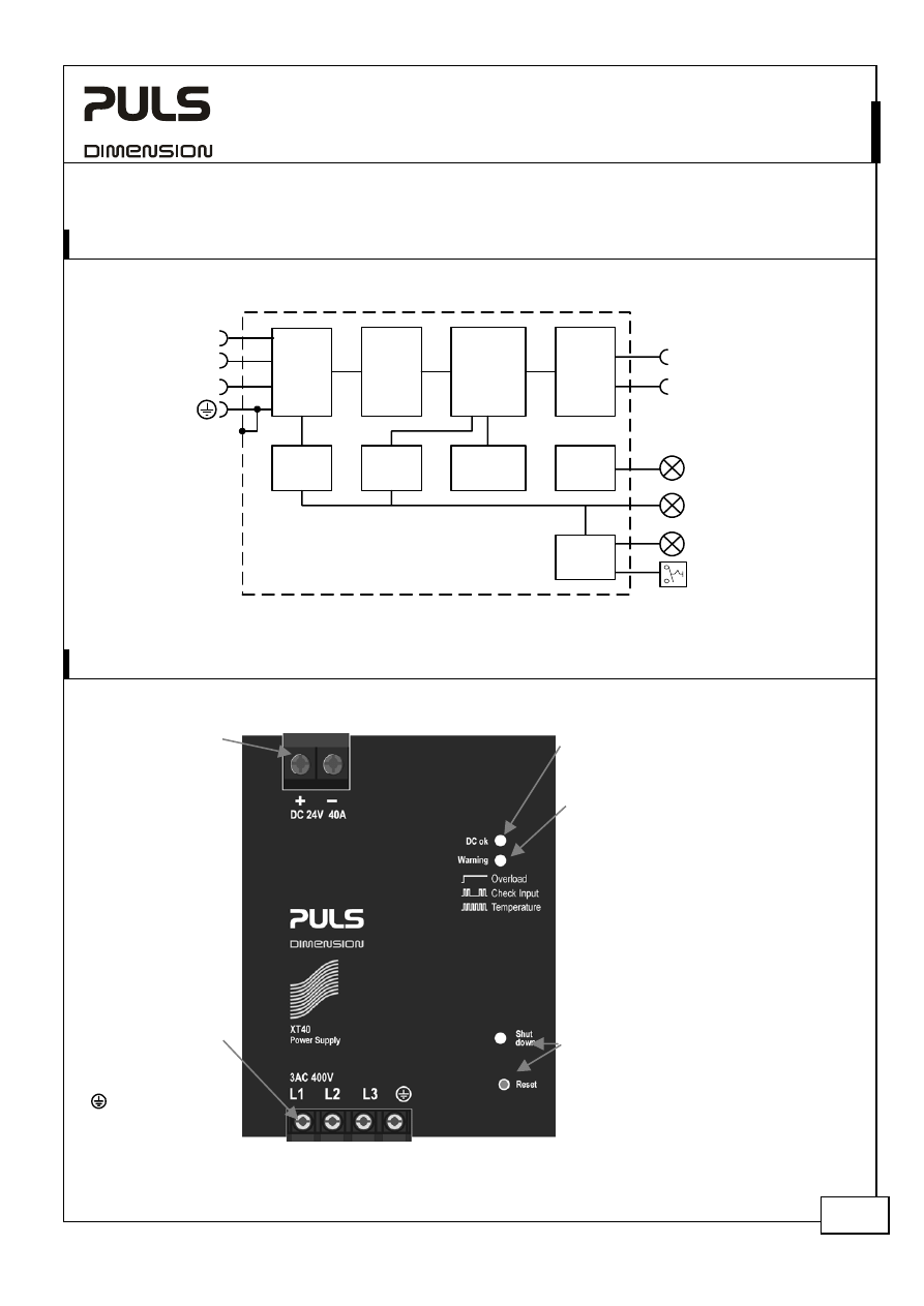
10. F
UNCTIONAL
D
IAGRAM
Fig. 10-1 Functional diagram
+
-
Active
Transient
Blocker
Input
Filter
Input
Rectifier
Reset
Output
Voltage
Monitor
Over-
Voltage
Protection
Output
Power
Manager
Temp.
Shut-
down
Input
Voltage
Monitor
L3
L2
L1
Semi-
regulated
Power
Converter
Output
Filter
DC-ok
LED
Warning
LED
Shut-down
LED
11. F
RONT
S
IDE AND
U
SER
E
LEMENTS
Fig. 11-1 Front side of XT40.241
Output Terminals
Large screw terminal
+ Positive output
- Negative (return)
output
See chapter 12
“Terminals and
Wiring” to choose
appropriate wire size.
Input Terminals
Screw terminals
L1, L2, L3:
Line inputs
PE (Protective
Earth) input
DC-ok LED (green)
Indicates a normal operation. The LED is on
if the output voltage is higher than 21.6V.
Warning LED (yellow)
- A steady-state light indicates an output
current higher than the nominal current
and that the internal shutdown timer is
running.
- A double flash indicates a phase-loss or
too low / too high input voltage.
(XT40.241: < 3x333Vac or > 3x467Vac
XT40.242: < 3x400Vac or > 3x560Vac)
- A fast flash warns of an impending
temperature shut-down. A shut-down
can be expected within 10 minutes, if
the ambient temperature or the load
current stays constant.
Shut-down LED (red) and reset button
The red LED flashes when the device has
shut down. Pressing the reset button or
cycling the input power (10s required)
initiates a restart. If the fault has been
cleared the device will operate normally.
XT40.241, XT40.242
– X-Series
24V, 40A, T
HREE
-P
HASE
I
NPUT
Jan. 2007 / Rev. 1.0 DS-XT40.24x-EN All parameters are specified at 24V 40A, 3x400Vac (XT40.241) or 3x480Vac (XT40.242),
25°C ambient and after a 5 minutes run-in time unless otherwise noted.
www.pulspower.com Phone +49 89 9278 0 Germany
9/20
12. T
ERMINALS AND
W
IRING
Use appropriate copper cables that are designed for a minimum operating temperatures of 60°C (for ambient up to
45°C) and 75°C (for ambient up to 60°C). Follow national installation codes and regulations! Ensure that all strands of
a stranded wire enter the terminal connection! Do not use the power supply without PE (Ground) connection! Up to
two stranded wires with the same cross section are permitted in one connection point (except PE wire). Ferrules are
allowed, but not required.
Input Output
Type
Screw terminal
Screw terminal
Solid
wire
0.5-6mm
2
0.5-16mm
2
Stranded
wire
0.5-4mm
2
0.5-10mm
2
American wire gauge
20-10 AWG
22-8 AWG
Wire stripping length
7mm / 0.26inch
12mm / 0.5inch
Recommended tightening torque
0.8Nm / 7lb.inch
1.2Nm / 10.6lb.inch
13. R
ELIABILITY
Lifetime expectancy
min.
51 000h
40°C, 24.1V, 40A
min.
t.b.d.
40°C, 24.1V, 20A
min.
142 000h
25°C, 24.1V, 40A
MTBF SN 29500, IEC 61709
529 000h
40°C, 24.1V, 40A
959 000h
25°C, 24.1V, 40A
MTBF MIL HDBK 217F
206 000h
40°C, 24.1V, 40A, Ground Benign GB40
276 000h
25°C, 24.1V, 40A, Ground Benign GB25
The Lifetime expectancy shown in the table above indicates the operating hours (service life) and is determined by
the lifetime expectancy of the built-in electrolytic capacitors.
Lifetime expectancy is specified in operational hours and is calculated according to the capacitor’s manufacturer
specification. The prediction model allows a calculation of up to 15 years from date of shipment.
MTBF stands for Mean Time Between Failure, which is calculated according to statistical device failures, and indicates
reliability of a device. It is the statistical representation of the likelihood of a unit to fail and does not necessarily
represent the life of a product.
XT40.241, XT40.242
– X-Series
24V, 40A, T
HREE
-P
HASE
I
NPUT
Jan. 2007 / Rev. 1.0 DS-XT40.24x-EN All parameters are specified at 24V 40A, 3x400Vac (XT40.241) or 3x480Vac (XT40.242),
25°C ambient and after a 5 minutes run-in time unless otherwise noted.
www.pulspower.com Phone +49 89 9278 0 Germany
10/20
14. EMC
The power supply is suitable for applications in industrial environments as well as in residential, commercial and light
industry environments without any restrictions. The CE mark is in conformance with EMC guideline 89/336/EEC and
93/68/EEC and the low-voltage directive (LVD) 73/23/EWG. A detailed EMC report is available on request.
EMC Immunity
EN 61000-6-1 and EN 61000-6-2
Generic standards
Electrostatic discharge
EN 61000-4-2
Contact discharge
Air discharge
8kV
15kV
Criterion A
Criterion A
Electromagnetic RF field
EN 61000-4-3 80MHz-1GHz
10V/m Criterion
A
Fast transients (Burst)
EN 61000-4-4
Input lines
Output lines
4kV
2kV
Criterion A
Criterion A
Surge voltage on input
EN 61000-4-5
L1 Æ L2, L2 Æ L3, L1 Æ L3
L1 / L2 / L3 Æ PE
2kV
4kV
Criterion A
Criterion A
Surge voltage on output
EN 61000-4-5
+ Æ -
+ / - Æ PE
500V
500V
Criterion A
Criterion A
Conducted disturbance
EN 61000-4-6
0.15-80MHz
10V
Criterion A
Mains voltage dips
EN 61000-4-11
0% of 400Vac
40% of 400Vac
70% of 100Vac
0% of 480Vac
40% of 480Vac
70% of 480Vac
20ms
200ms
500ms
20ms
200ms
500ms
Criterion B
Criterion C
Criterion C
Criterion B
Criterion C
Criterion C
Powerful transients
VDE 0160
over entire load range
1300V, 1.3ms
Criterion D
Criteria:
A: Power
supply shows normal operation behavior within the defined limits.
B: During the mains voltage dip, the output voltage will decrease according to curves in the section “Hold-up Time”. The unit works in normal mode
once the voltage dip is over. If criteria A is required, use one or two buffer modules UF20.241 in addition to the XT40 power supply.
C: Temporary loss of function is possible. Power supply might shut-down and restarts by itself. No damages or hazards for the power supply will occur.
D: The input transient blocker opens and the main converter is without input power during such transients. The output voltage decreases similar as
described in the hold-up time section during such an event.
EMC Emission
EN 61000-6-3 and EN 61000-6-4
Generic standards
Conducted emission
EN 55011, EN 55022, FCC Part 15, CISPR 11, CISPR 22
Class B, input lines
EN 55022
Class B, output lines
Radiated emission
EN 55011, EN 55022
Class B
Harmonic input current
EN 61000-3-2
Fulfilled, active PFC
Voltage fluctuations, flicker EN
61000-3-3
Fulfilled
This device complies with FCC Part 15 rules.
Operation is subjected to the following two conditions: (1) this device may not cause harmful interference, and (2) this
device must accept any interference received, including interference that may cause undesired operation.
Switching Frequency
Switching frequency
36kHz
nearly constant
XT40.241, XT40.242
– X-Series
24V, 40A, T
HREE
-P
HASE
I
NPUT
Jan. 2007 / Rev. 1.0 DS-XT40.24x-EN All parameters are specified at 24V 40A, 3x400Vac (XT40.241) or 3x480Vac (XT40.242),
25°C ambient and after a 5 minutes run-in time unless otherwise noted.
www.pulspower.com Phone +49 89 9278 0 Germany
11/20
15. E
NVIRONMENT
Operational temperature
-25°C to +70°C (-13°F to 158°F)
reduce output power above +60°C
Output de-rating
24W/°C
60-70°C (140°F to 158°F), see
Fig. 15-1
Storage temperature
-40 to +85°C (-40°F to 185°F)
storage and transportation
Humidity
5 to 95% r.H. no
condensation
allowed
Vibration
sinusoidal
2-17.8Hz: ±1.6mm; 17.8-500Hz: 2g
2 hours / axis
IEC 60068-2-6
Vibration
random
0.5m
2
(s
3
)
2 hours / axis
IEC 60068-2-64
Shock
15g 6ms, 10g 11ms
3 bumps / direction, 18 bumps in total
IEC 60068-2-27
Altitude
0 to 6000m (0 to 20 000ft)
Reduce output power or ambient
temperature above 2000m sea level.
Output de-rating (for altitude)
60W/1000m or 5°C/1000m
above 2000m, see
Fig. 15-2
Over-voltage
category
III
EN
50178, altitudes up to 2000m
II
Altitudes from 2000m to 6000m
Degree of pollution
2
EN 50178, non conductive
Fig. 15-1 Output current vs. ambient temp.,
Fig. 15-2 Output current vs. altitude
Allowed
Output Current
0
-25
0
20
40
70°C
10
20
30
40A
60
Ambient Temperature
Allowed Output
Current
0
0
2000
4000
6000m
10
20
30
40A
Altitude
A... Tamb < 60°C
B... Tamb < 50°C
C... Tamb < 40°C
A
B
C
The ambient temperature is defined 2cm below the unit.
XT40.241, XT40.242
– X-Series
24V, 40A, T
HREE
-P
HASE
I
NPUT
Jan. 2007 / Rev. 1.0 DS-XT40.24x-EN All parameters are specified at 24V 40A, 3x400Vac (XT40.241) or 3x480Vac (XT40.242),
25°C ambient and after a 5 minutes run-in time unless otherwise noted.
www.pulspower.com Phone +49 89 9278 0 Germany
12/20
16. P
ROTECTION
F
EATURES
Output
protection
Electronically protected against overload, no load and short circuits *)
Output over-voltage protection
max. 29.9Vdc
In case of an internal power supply failure, a redundant
circuit limits the maximum output voltage. The output
shuts-down and automatically attempts to restart.
Input overvoltage shut-down
typ. 3x 470Vac
XT40.241
typ. 3x 560Vac
XT40.242
Degree of protection
IP 20
EN/IEC 60529
Penetration protection
> 3.5mm
e.g. screws, small parts
Over-temperature
protection
yes
output shut-down, reset required
Input transient protection
MOV (Metal Oxide Varistor) and active transient blocker
Internal input fuse
not included
See section 26.4
*) An audible noise may be heard during a no load, overload or short circuit event.
17. S
AFETY
Input / output separation
SELV
IEC/EN 60950-1
PELV
EN 60204-1, EN 50178, IEC 60364-4-41
double or reinforced insulation
Class of protection
I
PE (Protective Earth) connection required
Isolation resistance
> 5MOhm
input to output, 500Vdc
PE resistance
< 0.1Ohm
between housing and PE terminal
Touch current (leakage current)
typ. 0.30mA
XT40.241: 3x400V, 50Hz, TN mains
< 0.35mA
XT40.241: 3x440V, 50Hz, TN mains
typ. 0.40mA
XT40.242: 3x480V, 60Hz, TN mains
< 0.45mA
XT40.242: 3x524V, 60Hz, TN mains
18. D
IELECTRIC
S
TRENGTH
Fig. 18-1 Dielectric strength
A B C
Type test
60s
2500Vac
3000Vac
500Vac
Factory test
5s
2500Vac
2500Vac
500Vac
Field test
5s
2000Vac
2000Vac
500Vac
A
C
B
L1
Input
Earth
Output
-
+
L3
L2
Type tests and factory tests:
Conducted by the manufacturer. Do not repeat these test in
the field!
Rules for field test:
Use appropriate test equipment which applies the voltage
with a slow ramp! Connect L1, L2 and L3 together as well as
all output poles.
The output voltage is floating and has no ohmic connection to ground. Grounding of output allowed.
To fulfill the PELV requirements according to EN60204-1 paragraph 6.4.1, PULS recommend that either the + pole or
the – pole shall be connected to the protective earth system. This helps to avoid situations in which a load starts
unexpectedly or cannot be switched off when an unnoticed ground fault occurs.
XT40.241, XT40.242
– X-Series
24V, 40A, T
HREE
-P
HASE
I
NPUT
Jan. 2007 / Rev. 1.0 DS-XT40.24x-EN All parameters are specified at 24V 40A, 3x400Vac (XT40.241) or 3x480Vac (XT40.242),
25°C ambient and after a 5 minutes run-in time unless otherwise noted.
www.pulspower.com Phone +49 89 9278 0 Germany
13/20
19. A
PPROVALS
IEC
60950-1
IECEE
CB SCHEME
CB Scheme,
Information Technology Equipment
UL
508
IND. CONT. EQ.
18WM
LISTED
LISTED for Industrial Control Equipment, E198865
UL
60950-1
RECOGNIZED E137006 recognized for the use in U.S.A. (UL 60950-
1) and Canada (C22.2 No. 60950)
Information Technology Equipment, Level 5
20. F
ULFILLED
S
TANDARDS
EN 61558-2-17
Safety of Power Transformers
EN/IEC 60204-1
Safety of Electrical Equipment of Machines
EN/IEC 61131-2
Programmable Controllers
EN 50178, IEC 62103
Electronic Equipment for Use in Power Installations
21. U
SED
S
UBSTANCES
The unit does not release any silicone and is suitable for the use in paint shops.
Electrolytic capacitors included in this unit do not use electrolytes such as Quaternary Ammonium Salt Systems.
Plastic housings and other molded plastic materials are free of halogens.
The materials used in our production process do not include the following toxic chemicals:
Polychlorinated Biphenyl (PCB), Pentachlorophenol (PCP), Polychlorinated naphthalene (PCN), Polybrominated
Biphenyl (PBB), Polybrominated Biphenyl Oxide (PBO), Polybrominated Diphenyl Ether (PBDE), Polychlorinated
Diphenyl Ether (PCDE), Polybrominated Diphenyl Oxide (PBDO), Cadmium, Asbestos, Mercury, Silica
XT40.241, XT40.242
– X-Series
24V, 40A, T
HREE
-P
HASE
I
NPUT
Jan. 2007 / Rev. 1.0 DS-XT40.24x-EN All parameters are specified at 24V 40A, 3x400Vac (XT40.241) or 3x480Vac (XT40.242),
25°C ambient and after a 5 minutes run-in time unless otherwise noted.
www.pulspower.com Phone +49 89 9278 0 Germany
14/20
22. P
HYSICAL
D
IMENSIONS AND
W
EIGHT
Weight
1400g / 3.09lb
DIN-Rail
Use 35mm DIN-rails according to EN 60715 or EN 50022 with a height of 7.5 or 15mm.
The DIN-rail height must be added to the depth (157mm) to calculate the total required
installation depth.
CAD files with mechanical data can be downloaded at www.pulspower.com
Fig. 22-1 Front view
Fig. 22-2 Side view
23. I
NSTALLATION AND
O
PERATION
I
NSTRUCTIONS
Mounting and installation:
Output terminal must be located on top and input terminal on the bottom. For other orientations see section 26.12.
An appropriate electrical and fire end-product enclosure needs to be considered in the end use application.
Cooling:
Convection cooled, no forced air cooling required. Do not block ventilation grill by more than 30%!
Installation clearances:
40mm on top, 20mm on the bottom, 5mm on the left and right side are recommended when loaded permanently
with full power. If the adjacent device is a heat source, 15mm clearance are recommended.
Risk of electrical shock, fire, personal injury or death!
Do not use the unit without proper earth connection (Protective Earth). Use the pin on the terminal block for earth
connection and not one of the screws on the housing.
Turn power off before working on the power supply. Protect against inadvertent re-powering.
Make sure the wiring is correct by following all local and national codes.
Do not open, modify or repair the unit.
Use caution to prevent any foreign objects from entering into the housing.
Do not use in wet locations or in areas where moisture or condensation can be expected
Service parts:
The unit does not contain any field replaceable parts. If damage or malfunctioning should occur, immediately turn
power off and send the unit back to the factory for inspection!
XT40.241, XT40.242
– X-Series
24V, 40A, T
HREE
-P
HASE
I
NPUT
Jan. 2007 / Rev. 1.0 DS-XT40.24x-EN All parameters are specified at 24V 40A, 3x400Vac (XT40.241) or 3x480Vac (XT40.242),
25°C ambient and after a 5 minutes run-in time unless otherwise noted.
www.pulspower.com Phone +49 89 9278 0 Germany
15/20
24. A
CCESSORIES
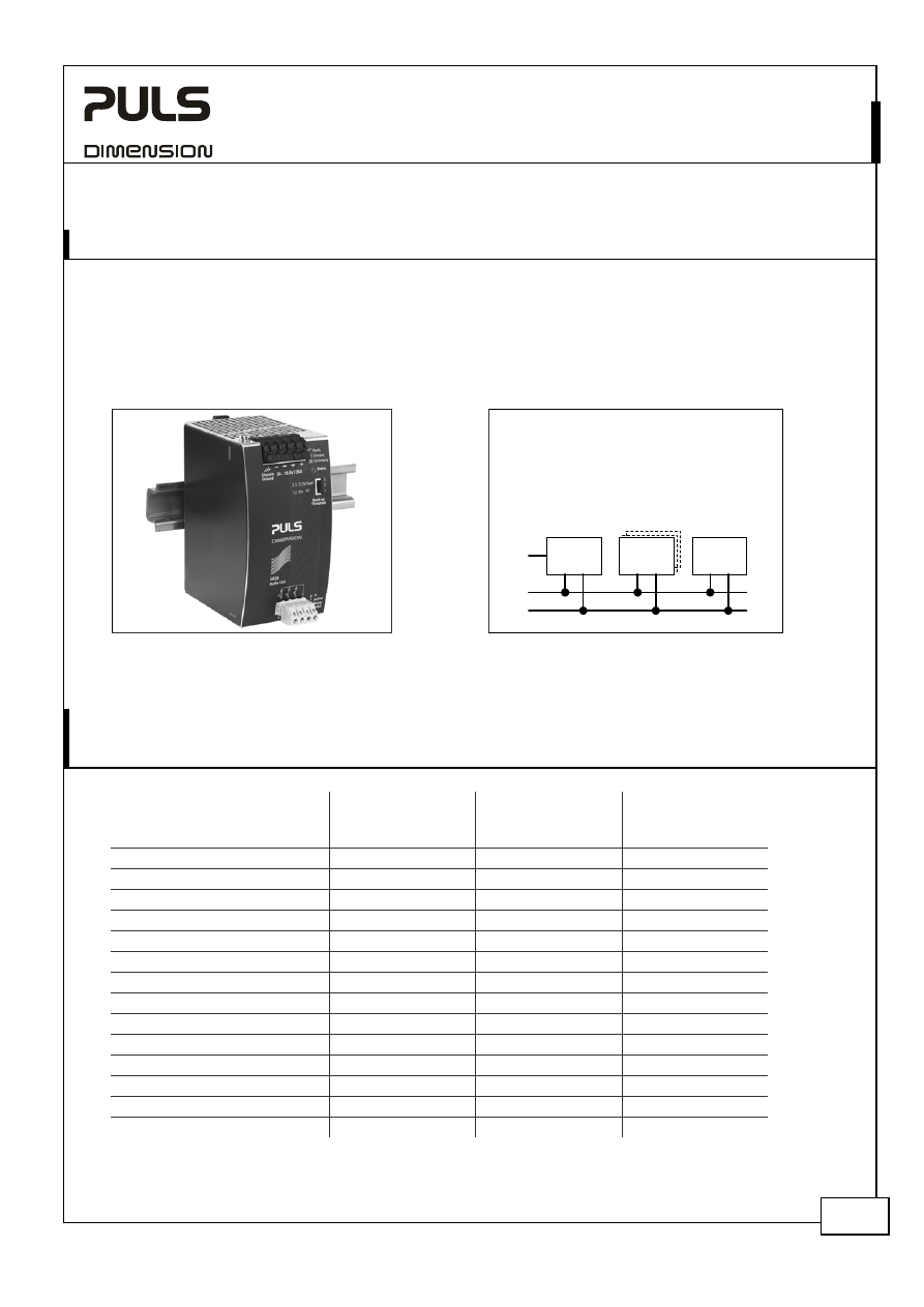
Buffer module UF20.241
This buffer unit is a supplementary device for DC24V power supplies. It delivers power to bridge typical mains failures
or extends the hold-up time after turn-off of the AC power. In times when the power supply provides sufficient
voltages, the buffer unit stores energy in integrated electrolytic capacitors. In case of mains voltage fault, this energy
is released again in a regulated process.
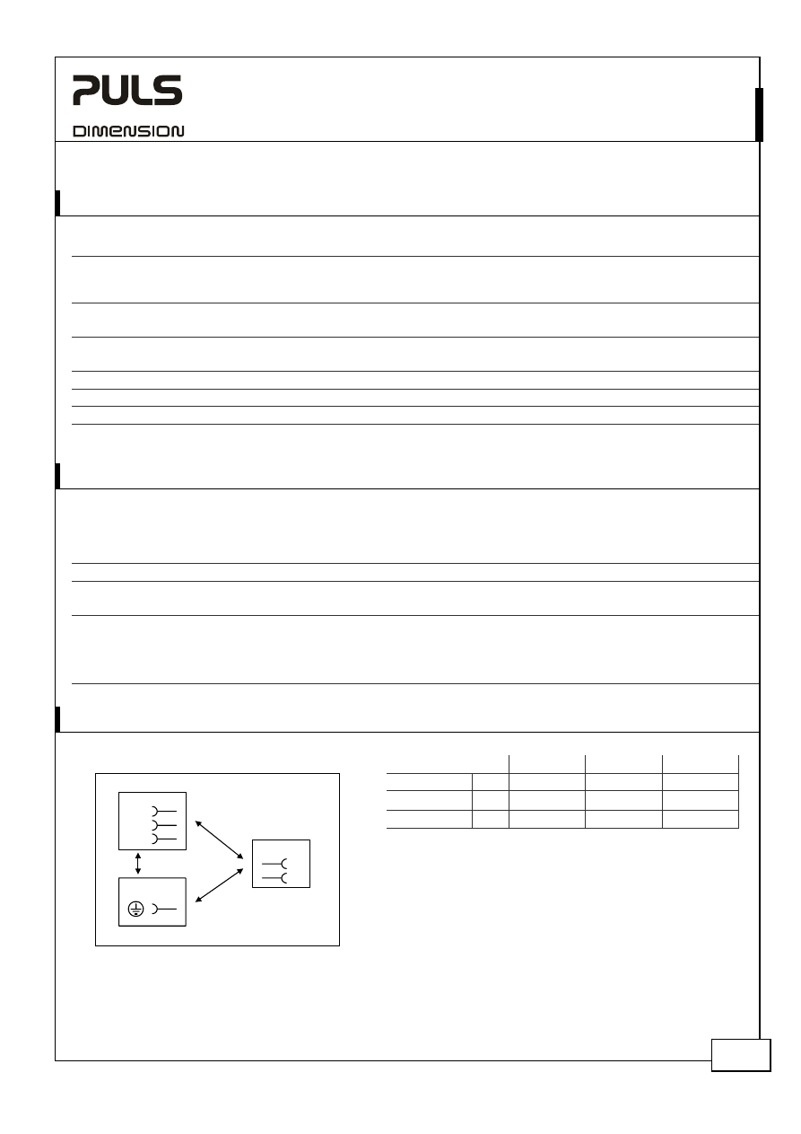
Fig. 24-1 Buffer module UF 20.241
Fig. 24-2 Wiring diagram XT40 and UF20.241
The buffer unit does not require any
control wiring. It can be added in parallel
to the load circuit at any given point.
Buffer units can be added in parallel to
increase the output ampacity or the hold-
up time.
Do not use the buffer module to bridge mains interruptions which are longer than typ. 350ms. Once the mains is off
for longer than typ. 350ms, the XT power supply needs an additional 1s to restart again.
25. C
OMPARISON BETWEEN THE
XT40,
A
T
RANSFORMER AND A
T
RADITIONAL
S
WITCHED
-
MODE
P
OWER
S
UPPLY
XT40 Semi-
regulated power
supply
Traditional
switched-mode
power supply
Transformer
power supply
Input voltage range
+ ++ -
Inrush current surge
++ + -
Hold-up time
- + -
Phase-loss operation
- + -
Efficiency
+++ ++ -
Output voltage regulation
+ ++ -
Output adjustment range
- ++ -
Ripple & noise voltage
- ++ -
Error diagnostics
++ ++ -
Harmonic distortion (PFC)
+ + -
EMC
++ ++ +
Ease of installation
++ ++ -
Size
+++ ++ -
Weight
+++ + -
+++…very, very good ++…very good +…good -…poor
DC
Buffer
Unit(s)
Power
Supply
Load
AC
+
-
XT40.241, XT40.242
– X-Series
24V, 40A, T
HREE
-P
HASE
I
NPUT
Jan. 2007 / Rev. 1.0 DS-XT40.24x-EN All parameters are specified at 24V 40A, 3x400Vac (XT40.241) or 3x480Vac (XT40.242),
25°C ambient and after a 5 minutes run-in time unless otherwise noted.
www.pulspower.com Phone +49 89 9278 0 Germany
16/20
26. A
PPLICATION
N
OTES
26.1. P
ERIODICAL
P
EAK
P
OWER
C
APABILITY
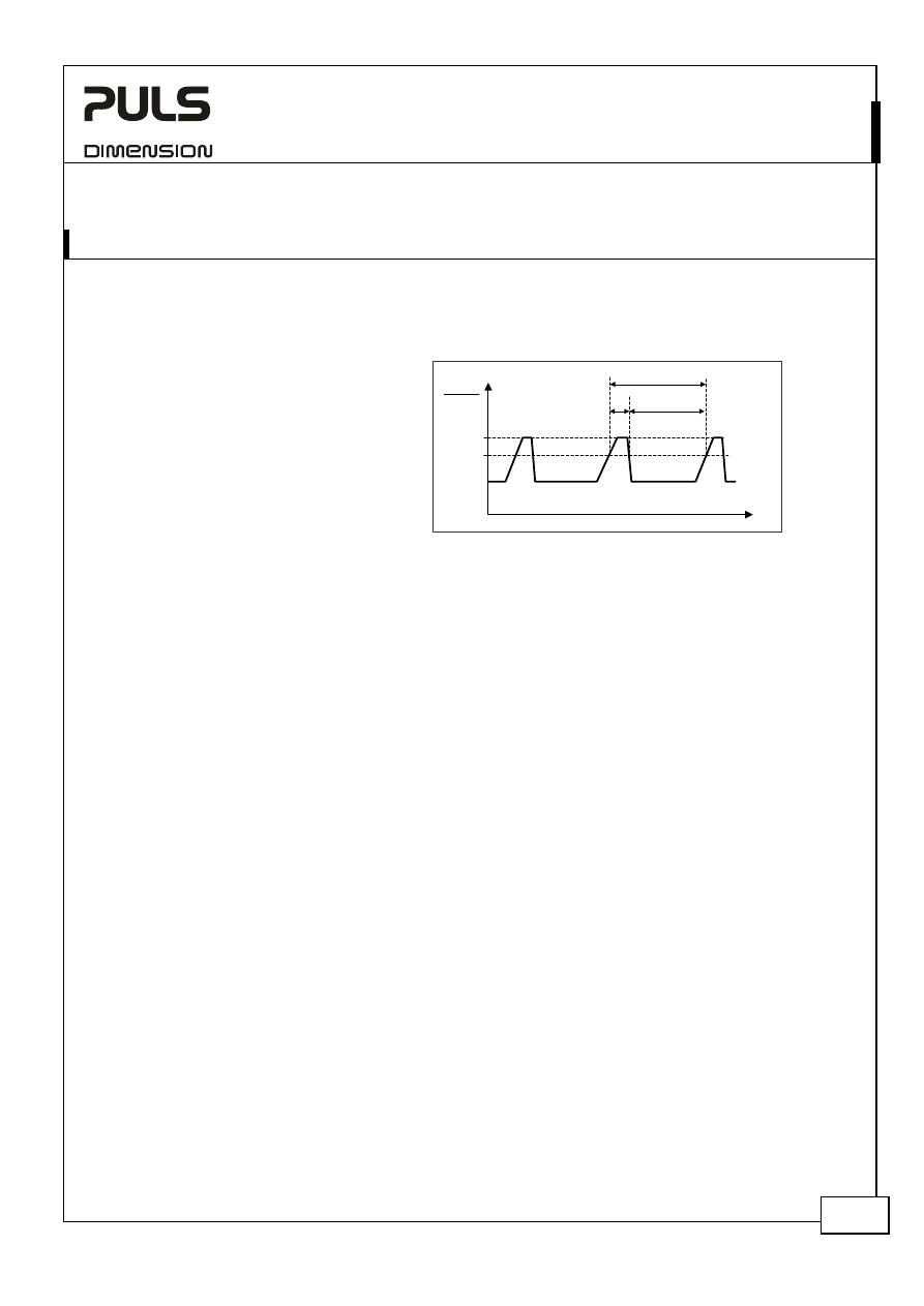
Fig. 26-Periodical peak power compatibility.
The short term power can be used
periodically.
The duration of the peak power (T
P
)
must be shorter than 15s.
The time between two peak power
pulses must be three times longer than
the duration of the preceding pulse
length.
t
T
100%
125%
P
OUT
P
NOM
T
P
> 3x T
P
26.2. C
HARGING OF
B
ATTERIES
The power supply shall not be used to charge batteries.
XT40.241, XT40.242
– X-Series
24V, 40A, T
HREE
-P
HASE
I
NPUT
Jan. 2007 / Rev. 1.0 DS-XT40.24x-EN All parameters are specified at 24V 40A, 3x400Vac (XT40.241) or 3x480Vac (XT40.242),
25°C ambient and after a 5 minutes run-in time unless otherwise noted.
www.pulspower.com Phone +49 89 9278 0 Germany
17/20
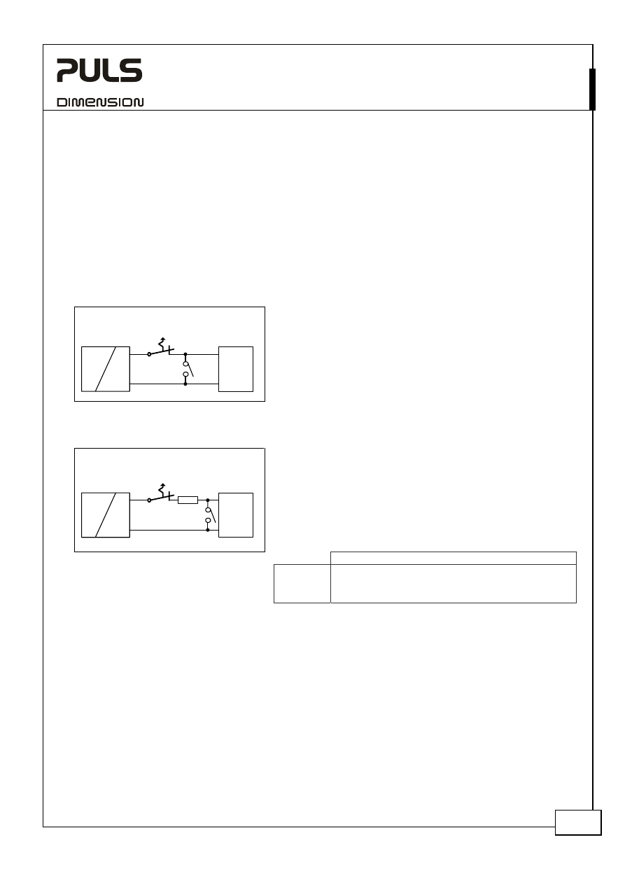
26.3. O
UTPUT
C
IRCUIT
B
REAKERS
Standard miniature circuit breakers (MCB`s or UL 1077 supplementary breakers) can be used for branch protection
but ensure, that the MCB is rated for DC voltage too. The following tests show which circuit breakers the power
supply typically will trip.
Circuit breakers have huge tolerances in their tripping behavior. Therefore, these typical tests can only be used as a
recommendation or for comparing two different power supplies. Furthermore, the loop impedance has a major
influence on whether a breaker trips or not. Two tests were performed, representing typical situations:
Test 1: Short circuit with S1 on the power supply end of the cable (loop impedance approx. 20mOhm)
Fig. 26-1 Branch protectors, test circuit 1
Circuit
Breaker
Power
Supply
AC
DC
+
-
I
Load
+
-
S1
Parameters:
Input voltage:
3x400Vac, load current: 0A
The following circuit breaker tripped during the test:
A- or Z- Characteristic:: equal or smaller 25A *)
B- Characteristic:
equal or smaller 32A *)
C- Characteristic:
equal or smaller 20A *)
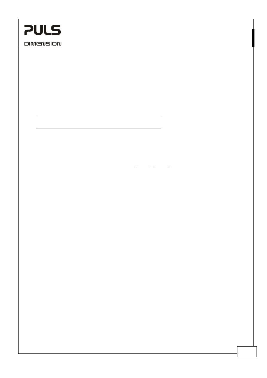
Test 2: Short circuit with S1 on the load end (additional impedance included; represents longer load wire length).
Fig. 26-2 Branch protectors, test circuit 2
R
Circuit
Breaker
Power
Supply
AC
DC
+
-
I
S1
Load
+
-
Parameters:
Input voltage:
3x400Vac, load current: 0A
The following circuit breaker tripped during the test:
A- or Z- Characteristic::
≤ 25A and R= 50mOhm *)
B- Characteristic:
≤ 25A and R= 50mOhm *)
C- Characteristic:
≤ 20A and R= 82mOhm *)
What does this resistance mean in wire length?
1.0mm
2
1.5mm
2
2.5mm
2
4.0mm
2
6.0mm
2
10mm
2
50mOhm
2.8m 4.2m 7.0m 11.1m
16.7m
27.9m
82mOhm
4.6m 6.9m 11.4m
18.3m
27.4m 45.7m
*) A list of the circuit breakers under test is available on request.
Example:
Which wire gauge must be used at a length of 10m before a B-Characteristic circuit breaker with 25A will trip?
Answer: A 25A B-Characteristic circuit breaker requires a loop impedance of less than 50mOhm based on the test
results. The wire length table shows that a length of 11.1m with a cross section of 4.0mm
2
has an impedance of
50mOhm. A wire not smaller than 4.0mm
2
shall be used.
XT40.241, XT40.242
– X-Series
24V, 40A, T
HREE
-P
HASE
I
NPUT
Jan. 2007 / Rev. 1.0 DS-XT40.24x-EN All parameters are specified at 24V 40A, 3x400Vac (XT40.241) or 3x480Vac (XT40.242),
25°C ambient and after a 5 minutes run-in time unless otherwise noted.
www.pulspower.com Phone +49 89 9278 0 Germany
18/20
26.4. E
XTERNAL
I
NPUT
P
ROTECTION
The power supply has no internal input fuses included. The unit is tested and approved for branch circuits up to 16A
(U.S.A 15A). External protection is only required if the supplying branch has an ampacity greater than this. In some
countries local regulations might apply so check all local codes and requirements. If an external fuse is necessary or
utilized, minimum requirements need to be considered to avoid nuisance tripping of the fuse.
B-Characteristic
C-Characteristic
Ampacity max.
20A 20A
min.
6A 3A
26.5. B
ACK
-
FEEDING
L
OADS
Loads such as decelerating motors and inductors can feed voltage back to the power supply. This feature is also called
return voltage immunity or resistance against Back- E.M.F. (Electro Magnetic Force).
This power supply is resistant and does not show adverse effects when a load feeds back voltage to the power supply.
It does not matter, whether the power supply is on or off.
If the power supply is fully loaded after a return-feeding event, the output voltage can dip to 21V for approx 20ms.
The maximum allowed feed back voltage is 28.9Vdc. The absorbing energy can be calculated according to the built-in
large sized output capacitor which is specified in chapter 7.
26.6. P
ARALLEL
U
SE TO
I
NCREASE
O
UTPUT
P
OWER
The XT40 Series of power supplies shall not be paralleled to increase the output power.
26.7. P
ARALLEL
U
SE FOR
R
EDUNDANCY
Power supplies can be paralleled for a 1+1 redundancy to gain a higher system availability and reliability. Redundant
systems require a certain amount of extra power to support the load in case one power supply unit fails. The simplest
way is to put two X-Series power supplies in parallel which is called a 1+1 redundancy. In case one power supply unit
fails, the other one is automatically able to support the load current without any interruption.
Please note: This simple way to build a redundant system does not cover failures such as an internal short circuit on
the secondary side of the power supply. In such a condition, the shorted unit becomes a load for the other power
supplies and the output voltage can not be maintained. This can be avoided by utilizing decoupling diodes which are
included in the SilverLine redundancy module SLR01.
Recommendations for building redundant power systems:
a)
Use separate input fuses for each power supply.
b)
Monitor the individual power supply units. A DC-ok LED and a DC-ok contact is included in the redundancy
module SLR01and can report a faulty unit.
XT40.241, XT40.242
– X-Series
24V, 40A, T
HREE
-P
HASE
I
NPUT
Jan. 2007 / Rev. 1.0 DS-XT40.24x-EN All parameters are specified at 24V 40A, 3x400Vac (XT40.241) or 3x480Vac (XT40.242),
25°C ambient and after a 5 minutes run-in time unless otherwise noted.
www.pulspower.com Phone +49 89 9278 0 Germany
19/20
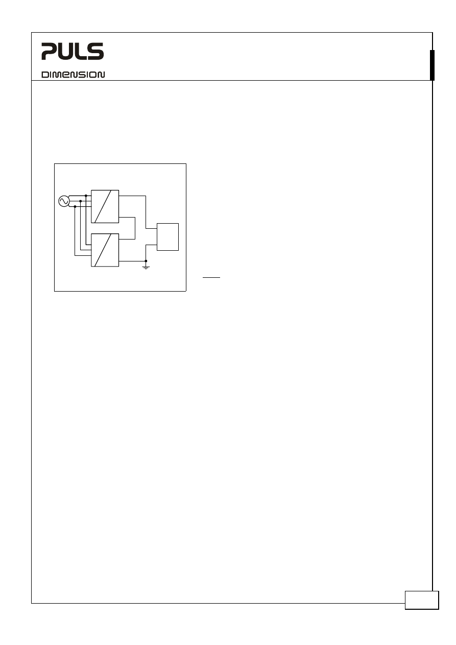
26.8. S
ERIES
O
PERATION
The power supplies of the X-Series can be put in series to increase the output voltage.
Fig. 26-3 Schematic for series operation
Installation notes for use in series:
Unit B
-
+
Load
+
-
AC
DC
AC
DC
-
+
Unit A
Earth
(see notes)
a)
It is possible to connect as many units in series as needed,
providing the sum of the output voltage does not exceed
150Vdc.
b)
Voltages with a potential above 60Vdc are no longer rated SELV
and can be hazardous in some situations. Such voltages must be
installed with a protection to make the unit touch-safe.
c)
For serial operation use power supplies of the same type.
d)
Earthing of the output is required when the sum of the output
voltage is above 60Vdc.
e)
Keep an installation clearance of 15mm (left/right) between two
power supplies and avoid installing the power supplies on top of
each other.
Note: Avoid return voltage (e.g. from a decelerating motor or
battery) which is applied to the output terminals.
26.9. I
NDUCTIVE AND
C
APACITIVE
L
OADS
The unit is designed to supply any kind of loads, including inductive loads or capacitive loads with a capacity of up
to160mF.
26.10. L
OSS OF
O
NE
I
NPUT
P
HASE
The unit protects itself against a loss of one input phase and does not require an external protection device.
A phase-loss operation is possible for output currents below 8A. Above this level, the yellow LED indicates an
impending shut-down. If the missing phase does not recover, the unit switches off after 3.5s. Pressing the reset
button or cycling the input power (10s required) initiates a restart.
Please note that the input current and the output ripple are higher during the time when one phase is missing.
26.11. U
SE IN A
T
IGHTLY
S
EALED
E
NCLOSURE
When the power supply is installed in a tightly sealed enclosure, the temperature inside the enclosure will be higher
than outside. The inside temperature defines the ambient temperature for the power supply.
Results from such an installation:
Power supply is placed in the middle of the box, no other heat producing equipment inside the box
Enclosure:
Rittal Typ IP66 Box PK 9519 100, plastic, 180x180x165mm
Load:
24V, 32A (=80% of the rated current); load is placed outside the box
Input:
3x400Vac
Temperature inside the box:
54.9°C (in the middle of the right side of the power supply with a distance of 2cm)
Temperature outside the box:
25.7°C
Temperature rise:
29.7K
XT40.241, XT40.242
– X-Series
24V, 40A, T
HREE
-P
HASE
I
NPUT
Jan. 2007 / Rev. 1.0 DS-XT40.24x-EN All parameters are specified at 24V 40A, 3x400Vac (XT40.241) or 3x480Vac (XT40.242),
25°C ambient and after a 5 minutes run-in time unless otherwise noted.
www.pulspower.com Phone +49 89 9278 0 Germany
20/20
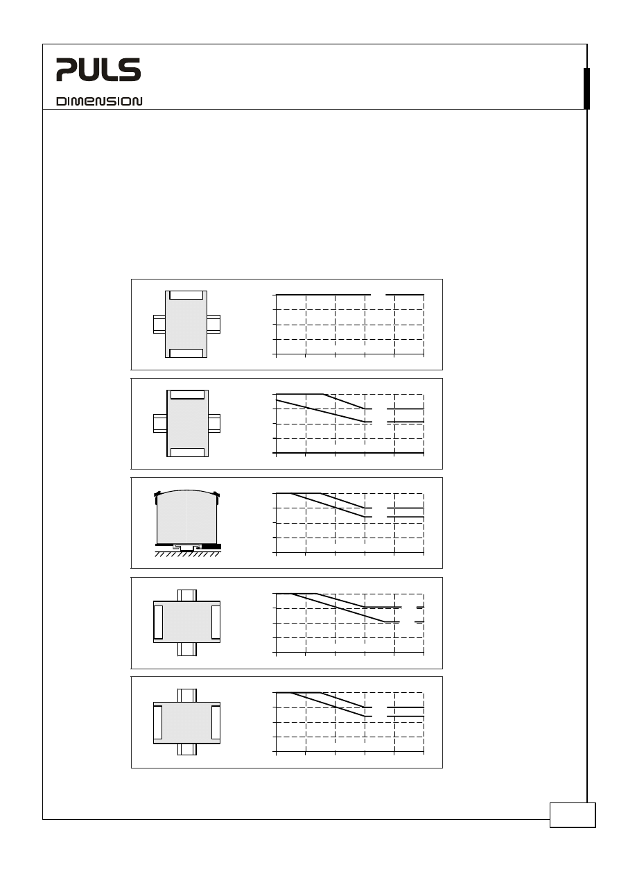
26.12. M
OUNTING
O
RIENTATIONS
Mounting orientations other than input terminals on the bottom and output on the top require a reduction in
continuous output power or a limitation in the max. allowed ambient temperature. The amount of reduction defines
the lifetime expectancy of the power supply. Therefore, two different derating curves for continuous operation can
be found below:
Curve A1
Recommended output current to achieve a minimum lifetime expectancy of 50 000h at 40°C ambient.
Curve A2
Max allowed output current for a safe operation (results approx. in half the lifetime expectancy of A1).
Fig. 26-4
Mounting
Orientation A
Standard
Orientation
Power
Supply
OUTPUT
INPUT
Output Current
0
10
20
30
40
60°C
10
20
30
40A
50
A1
Ambient Temperature
Fig. 26-5
Mounting
Orientation B
(Upside down)
Pow
er
Suppl
y
OUTP
UT
INPU
T
Output Current
0
10
20
30
40
60°C
10
20
30
40A
50
A2
Ambient Temperature
A1
Fig. 26-6
Mounting
Orientation C
(Table-top
mounting)
Output Current
0
10
20
30
40
60°C
10
20
30
40A
50
Ambient Temperature
A1
A2
Fig. 26-7
Mounting
Orientation D
(Horizontal cw)
Po
w
er
S
uppl
y
OUT
P
UT
INP
U
T
Output Current
0
10
20
30
40
60°C
10
20
30
40A
50
Ambient Temperature
A1
A2
Fig. 26-8
Mounting
Orientation E
(Horizontal ccw)
Po
w
er
S
uppl
y
OUT
P
UT
INP
U
T
Output Current
0
10
20
30
40
60°C
10
20
30
40A
50
Ambient Temperature
A1
A2
Wyszukiwarka
Podobne podstrony:
Datasheet QS10 241 C1
Datasheet QT20 241 C1
Datasheet QS20 241
Datasheet ML15 241
Datasheet XT40 361
Datasheet XT40 721
Datasheet CD5 241
Datasheet UF20 241
Datasheet XT40 481
Datasheet QT20 241
Datasheet QS20 241 C1
Datasheet QTD20 241
Datasheet CS10 241
Datasheet UB10 241
Datasheet QS5 241
Datasheet QS3 241
Datasheet CS5 241 C1
Datasheet CS3 241
więcej podobnych podstron