sla4e100 / 061020
1 / 4
Data
sheet
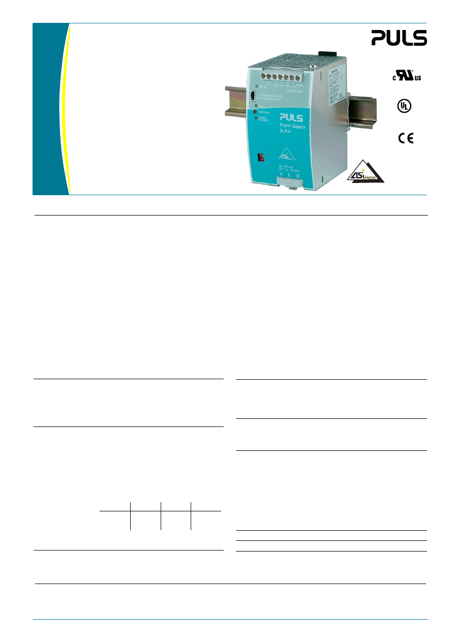
AS-Interface
Power Supply with 4A
SLA4.100
• Input: AC 115V / 230V
• Output: 30.5V / 4A
• AS Interface data decoupling
• Infrared (IR) addressing mode
• For highly demanding industrial
applications
• Ground Fault (GF) detector with
signal output
Input
Rated voltage
AC100-120/220-240V
(selectable by front panel slide switch)
Rated current
2.7A (switch in 115V position)
1.3A (switch in 230V position)
Frequency
47...63 Hz (alternatively DC also possible)
Voltage range
AC 85...132V/184...264V, DC 240...300V
Harmonic current
emissions
EN 61000-3-2 [PFC], Class A limits are fulfilled
Integrated internal
fuse
T3A15/250V HBC (not accessible)
Inrush current
limited by NTC resistor
T
amb
= +50°C, cold start
(line impedance acc. EN 61000-3-3)
Hold-up time
>30ms @ AC 100V or 196V and rated load
(also see diagram)
AC 120V
AC 132V
AC 230V
AC 264V
Peak current I
pk
<44.7A
<49.3A
<49.7A
<57.5A
I
2
t
<3.7A
2
s
<4.6A
2
s
<2.5A
2
s
<3.3A
2
s
Output
Rated voltage
DC 30.5V ±3% (not adjustable)
Rated current
4.0A
Isolation
Safe low voltage
PELV (IEC 60364-4-41)
SELV (IEC 60950)
Current limitation
>4.2 A
Overload behaviour
Continuous current (also see diagram)
Short-circuit current
>4.2A, <6.5A
Load regulation
stat. <250mV (no load / full load)
Line regulation
stat. <10mV (AC 85...132V/184...264V)
Ripple
<50 mV
PP
(500kHz bandw., 50
Ω measurem.,
ohmic load)
Noise (Spikes)
<150mV
PP
(20MHz bandw., 50
Ω measurem.,
ohmic load)
Over-voltage protection max. 55V
Operating indictor
Green LED (extinguishes at overload)
Output is protected against short-circuit, open circuit and overload.
Use AS-Interface power supplies only together with AS-Interface lines.
Data and energy:
The primary switched mode DIN rail power supply SLA4.100 specifically
supplies AS Interface
®
systems with energy. The AS-Interface bus tech-
nology allows to connect up to 62 participants to a control and to supply
them with energy with a single two-conductor cable. When connecting
slaves, the yellow AS-Interface cable offers the high degree of protection
IP67 in conjunction with the insulation displacement. The communica-
tion signals of the individual network participants are modulated onto
the supply voltage. For this purpose, specific power supply units with in-
tegrated data decoupling are required for AS-Interface systems.
Fast addressing of slaves:
The "IR addressing mode" selectable via jumper interrupts the data com-
munication on the yellow AS-Interface cable. Participants with an infra-
red interface can then quickly be assigned a new ID address by means of
an infrared programming unit without the need to disconnect them
from the AS-Interface cable. Afterwards, the "Communication Mode"
can be selected again to restart the data communication.
Worldwide operation:
This compact primary switched-mode built-in power supply can be oper-
ated on all usual single-phase line voltages. Its design corresponds to in-
ternational standards. The CE-Declaration allows for industrial and office
application.
Ground fault detector:
Acc. to EN60204 part 1 and DIN VDE0113 respectively, ground faults in
control circuits must neither cause a machine to start inadvertently or to
dangereously move nor prevent a controlled shutdown. The internal
SLA4 ground fault dectector makes external ground fault detector mod-
ules redundant. The AS-Interface network is monitored by the power
supply unit via the AS-Interface cable connected to the various partici-
pants. Detected ground faults are stored and signalled via front panel
LEDs and relay contacts. The ground fault detector may be manually
checked using the test/reset button.
Order information
Order number
Description
SLA4.100
SLZ13
SLZ02
AS-Interface power supply unit
Adapter for S7-300 rail
Wall mounting set (two pcs. per package)
Short description
Appr. No. 41801
EMC and
Low Volt.
Directive
CUL/CSA-C22.2
UL60950 E137006
No 60950
UL508 LISTED
IND. CONT. EQ.
18 WM, 60°C
2 / 4
sla4e100 / 061020
SLA4.100
Data sheet
Ground fault detector
Operating and environmental data
The ground fault detector monitors ground faults on the AS-Interface
lines and includes a self-test feature. The ground fault feature consists
of the LED 'Ground Fault (GF)', a 'Test/Reset' push-button and a relay
output. In case of failure, the output voltage will not switch off. For
proper functioning, it is essential to connect the shield terminal to PE
or machine ground. The AS-Interface network must not contain any
other ground fault detectors or insulation monitoring devices.
LED 'Ground Fault (GF)' displays a current or stored ground fault
push-button 'Reset/test'
• push <2s
• push >2s
to start test function
to reset stored ground fault
Ground fault relay
• max. V
switch
• max. I
switch
normally closed contact (NC); opens in the
event of ground fault
AC 25V or DC 60V
0.5A
Non-operating
temperature range
-25°C...+85°C
Operating
temperature range
-10°C...+70°C
(measured at 25mm below the unit)
Derating
from 60°C onwards 3W/K power reduction
necessary (see diagram)
Cooling
natural convection,
no forced air-cooling necessary
Over-temperature
protection
not implemented
Humidity
protect from moisture and condensation
Vibration
• Sinus
• Random
2 – 17.8Hz ±1.6mm (IEC 60068-2-6)
17.8Hz – 500Hz
2g (IEC 60068-2-6)
2...800Hz 0.5m
2
(s
3
) (IEC 60068-2-64)
Shock
15g (6ms), 10g (11ms), IEC 60068-2-27
Degree of pollution
2 (EN 60950)
Overvoltage category II (IEC 60950; IEC 60664), III (EN 50178)
Electromagnetic Compatibility (EMC)
Efficiency, Reliability
Emissions
EN 61000-6-3 (also includes EN 61000-6-4)
Class B (EN 55011, EN 55022)
EN 61000-3-2 and EN 61000-3-3
Immunity
• Electrostatic
Discharge (ESD)
EN 61000-6-2 (also includes EN 61000-6-1),
EN 61000-4-2, Level 4
(withstands 8 kV direct discharge,
15 kV air discharge)
• Electromagnetic
radiated fields
EN 61000-4-3, Level 3 (10 V/m)
• Burst, coupled to:
– ACin lines
– DCout lines
– Signal lines
EN 61000-4-4,
Level 4 (4 kV)
Level 3 (2 kV)
Level 3 (1 kV)
• Surge transients
– Differential
mode (L
→PE,
N
→PE)
– Common mode
(L
→ N)
EN 61000-4-5,
Installation class 4 (4 kV)
Installation class 4 (2 kV)
• Conducted noise
immunity
EN 61000-4-6,
Level 3 (10V, 150 kHz-80 MHz)
• Voltage dips
EN 61000-4-11
• Transient
immunity
Transient resistance acc. to VDE 0160 / W2
over entire load range
Efficiency
typ. 90%
(AC 230V, 4A)
Power dissipation
typ. 13.5W (AC 230V, 4A)
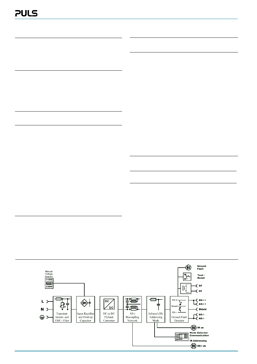
Schematic
sla4e100 / 061020
3 / 4
SLA4.100
Data sheet
Connectors and terminals
Front elements
Terminals
Fingertouch-proof terminals with captive
screws for 5.5mm slotted screwdriver or Philips
cross-recessed screwdriver No. 2
Position
Easy to reach terminals on the front panel;
input and output clearly separate from each
other
Tightening torque
0.8Nm
Wire gauge
• flexible cable
• solid cable
0.5-4mm
2
(20-10AWG)
0.5-6mm
2
(20-10AWG)
Ferrules
admissible
Stripping length
7mm
PE teminal
N
Input neutral
L
Input phase
GF ok
Ground Fault (GF) output (twice); normally
closed contact relay type, signals ground fault
brown
Positive AS-Interface output voltage (twice)
blue
Negative AS-Interface output voltage (twice)
Shield
Connection of machine ground
(Functional earth for balancing the AS-Inter-
face output. Connection is recommended for
EMC)
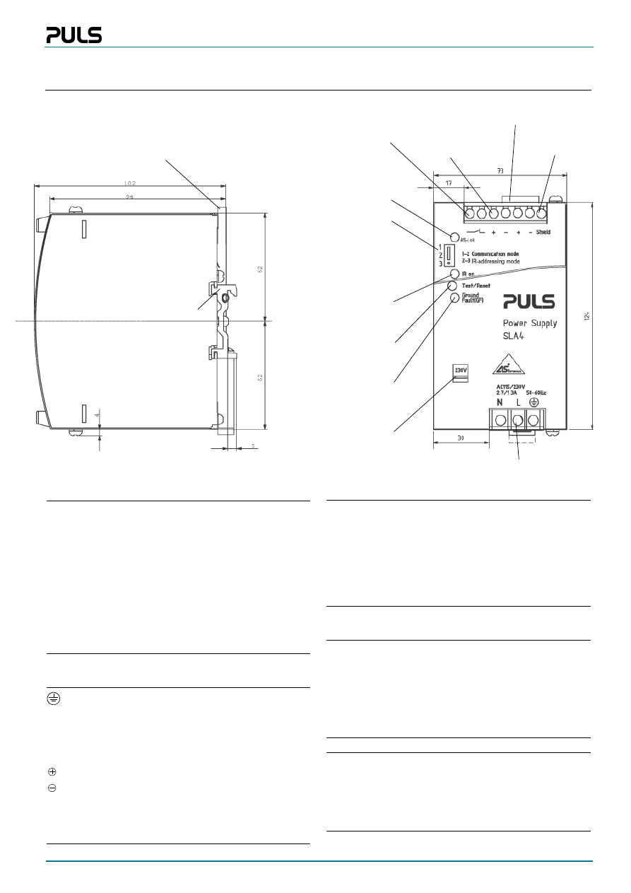
Construction / Mechanics
Installation notes
Housing
Robust metal housing for built-in installation
Degree of protection
IP20 (EN 60529)
Class of protection
1 (IEC 60536);
do not use without protective earth (PE)
Width w
Height h
Depth d
73 mm
124 mm
102 mm (without DIN rail)
Weight
650g
External fusing
• not necessary (internal fuse)
• observe national regulations
• circuit breaker with B-characteristic min. 6A
or slower action, or alternatively 6A HBC
fuse
Mounting position
vertical; input below, output above
Free space for cooling above / below 25mm recommended
left / right 15mm recommended
Always connect PE before operating the unit!
Operation without AS-Interface: This AS-Interface PSU has an in-
ductive output. When operating without AS-Interface structure (e.g. in
a laboratory test) you should connect a 470µF / 35V capacitor between
AS-Interface + and AS-Interface – as commercial electronic loads in
combination with the data decoupling often tend to oscillate, and the
oscillation may exceed the permitted modulation voltage. Otherwise,
equipment may be destroyed.
Operating indicators and elements
115/230V switch:
Slide switch to select the
input voltage range
DIN-rail mouting bracket
Plastic slider:
• Mounting: Place the unit onto the DIN-rail and push it
downwards and against the lower front edge until it
snaps into place.
• Detachment: Push downwards and detach the unit from
its DIN-rail mounting bracket.
Output terminals:
Dual terminals for
AS-Interface + and
AS-Interface –
Input terminals
Machine ground
connection
Green LED:
ON: AS-Interface volt-
age is within the limits
OFF: at overload
or missing input voltage
Red LED:
ON: Jumper position 2-3
OFF: Jumper position 1-2
Plug-in jumper:
Pos. 1-2: regular AS-In-
terface communication
Pos. 2-3: Data commu-
nication is interrupted.
IR-addressing can be
carried out
Plastic slider
Ground fault relay output:
Closed: no ground fault
Open: ground fault
Red LED:
ON: ground fault or stored
ground fault
OFF: faultless operation
Button:
Push <2s: test function
Push >2s: ground fault is reset
Your partner in power supply:
European
Power Supply
Manufacturers
Association
PULS GmbH
Arabellastraße 15
D-81925 München
Tel.: +49 89 9278-0
www.puls-power.com
Fax: +49 89 9278-199
SLA4.100
Data sheet
4 / 4
sla4e100 / 061020
Bayerns Best 50
Czech 100 Best
Europe’s 500
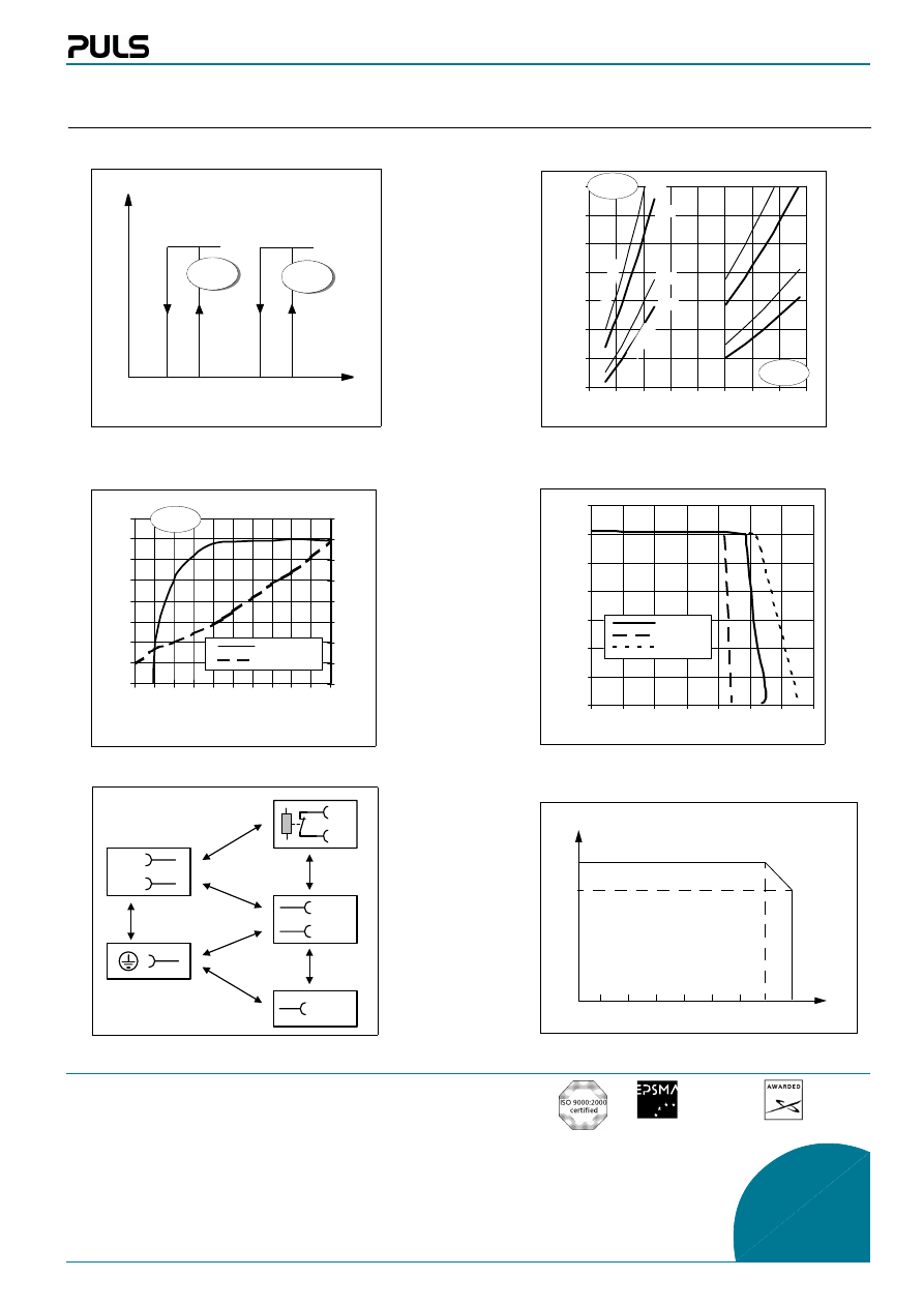
Functional diagrams
76
78
80
82
84
86
88
90
92
0 0,4 0,8 1,2 1,6 2 2,4 2,8 3,2 3,6 4
Output current Iout [A]
Efficiency [%]
0
2
4
6
8
10
12
14
16
Power
loss P
lo
ss
[W]
Efficiency
Power loss
10
30
50
70
90
110
130
150
70
95
120 145 170 195 220 245 270
Input voltage V ACin [V]
Ho
ld
-u
p ti
me
[ms
]
0
5
10
15
20
25
30
35
0
1
2
3
4
5
6
7
Output current Iout [A]
Output voltage Vout [V]
AC 230V
min
max.
Derating
Efficiency / Power dissipation
Start behaviour
Hold-up time
115 V
position
230 V
position
Output characteristic / Overload behaviour
I
max
(P
max
)
4A
3A
-10°C
0°C
10°C
20°C
30°C
40°C
50°C
60°C
70°C
T
amb
5
0
%
l
o
a
d
fu
ll
lo
ad
min.
typ.
typ.
min.
230 V
position
Unless otherwise stated, specifications are valid for AC 230V input voltage, +25°C ambient temperature, and 5 min. run-in time. They are subject to change without prior notice.
U
Out
U
In
115V
switch pos.
65
Vac
81
Vac
11
8 Vac
16
0 Vac
30.6V
230V
switch pos.
GF
GF
Shield
L
N
AS-i +
AS-i -
3.0
00V
ac
500
Vac
2.500Vac
500Vac
50Vac
50V
ac
3.000V
ac
Insulation diagram
Wyszukiwarka
Podobne podstrony:
Datasheet SL4 100
Datasheet SLR2 100
Datasheet SL30 100
Datasheet SL20 100
Datasheet SLD2 100
Datasheet MLY2 100
Datasheet SLR10 100
Datasheet ML70 100
Datasheet SLA3 100
Datasheet ML30 100
Datasheet SL10 100
Datasheet SL2 100
Datasheet ML50 100
Datasheet ML95 100
Datasheet SL5 100
Datasheet SLA8 100
Datasheet SLR5 100
więcej podobnych podstron