
Chapter
3
Flying Insects
The best model of a cat for biologists is another or better, the
same cat.
N. Wiener (1894-1964)
This Chapter reviews biological principles related to flight control in
insects. In the search for biological principles that are portable to artificial
implementation in lightweight flying robots, the review is organised into
three levels of analysis that are relevant for the control of both robots and an-
imals: sensors (perceptive organs), information processing, and behaviour.
This book has its main interest in flying insects since they face con-
straints that are very similar to those encountered by small aerial robots,
notably a minimal power consumption, ultra-low weight, and the control
of fast motion in real time. Relying on animal taxonomy, we first briefly
discuss which insects are the most interesting in our endeavour and why.
3.1
Which Flying Insects?
The animal kingdom is divided into phyla, among which the arthropods
are composed of four classes, one of those being the insects. Arthropods
are invertebrate animals possessing an exoskeleton, a segmented body, and
jointed legs. The compound eyes of arthropods are built quite differently
© 2008, First edition, EPFL Press
32
Which Flying Insects?
as opposed to eyes of vertebrates. They are made up of repeated units called
ommatidia, each of which functions as a separate visual receptor with its own
lens (see
).
Among arthropods, the most successful flying animals are found in the
insect class, which is itself divided into orders such as Diptera (flies and
mosquitoes), Hymenoptera (bees), Orthoptera (grasshoppers), Coleoptera
(beetles), Lepidoptera (butterflies), Isoptera (termites), Hemiptera (true
bugs), etc. This book focuses mainly on Diptera and Hymenoptera, not
only because flies and bees are generally considered to be the best flyers, but
also because a few species of these two orders, namely the blowflies (Cal-
liphora), the houseflies (Musca), the fruitflies (Drosophila), and the honey-
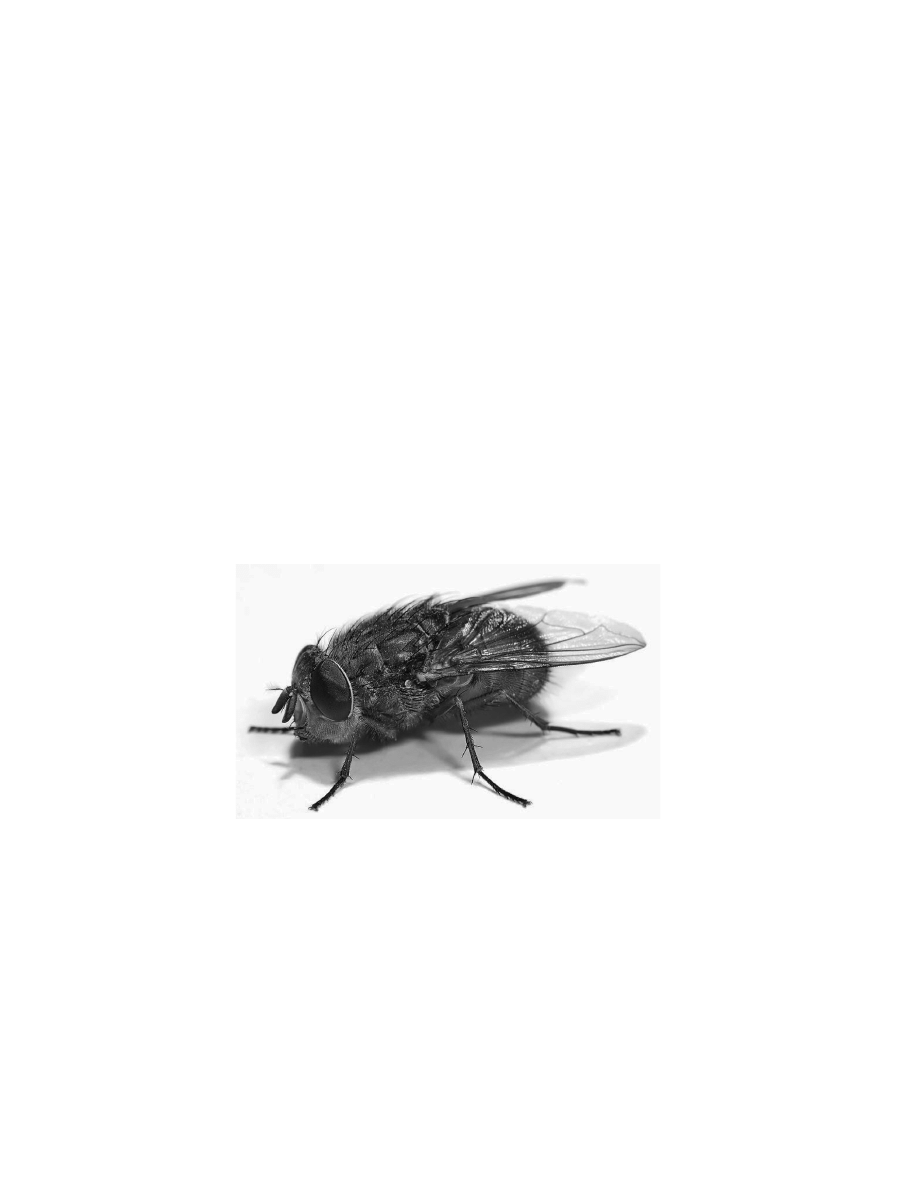
bees (Apis), have been extensively studied by biologists (Fig. 3.1). Almost
all insects have two pairs of wings, whereas Diptera feature only one pair.
Their hind wings have been transformed through evolution into tiny club-
shaped mechanosensors, named
halteres, which provide gyroscopic informa-
tion (see
).
Figure 3.1 An example of highly capable and thoroughly studied flying insect:
the blowfly Calliphora. Copyright by Flagstaffotos.
The sensory and nervous systems of flies have been analysed for decades,
which has resulted in a wealth of electrophysiological data, models of infor-
mation processing and behavioural descriptions. For example, many neu-
rons in the fly’s brain have been linked to specific visually-guided behaviours
© 2008, First edition, EPFL Press

Flying Insects
33
[Egelhaaf and Borst, 1993a]. Although honeybees are capable of solving
a great variety of visually controlled tasks [Srinivasan
et al., 1996, 2000],
comparatively little is known about the underlying neuronal basis. How-
ever, interesting models of visually guided strategies are available from be-
havioural studies.
Perception and action are part of a single closed loop rather than sep-
arate entities, but subdividing this loop into three levels helps to high-
light the possibilities of artificial implementation. At the first level, the
anatomical description of flying insects can be a source of inspiration for
constructing a robot. Although this book is not oriented toward mechan-
ical biomimetism, the choice of sensor modalities available on our robots
) is based on perceptive organs used by insects. At the second level,
models of biological information processing will guide us in the design of
sensory signal processing (
). Mainly related to vision, these models
have been essentially produced from neurophysiological studies or from be-
havioural experiments with tethered animals (see, e.g.
1993a). At the third level, the study of free-flight behaviour (ethology) pro-
vides significant insight into how insects steer in their environments and
manage to take full advantage of their sensor characteristics by using spe-
cific, stereotyped movements. Similar behaviours are implemented in our
robots (
).
In the remainder of this Chapter, existing descriptions of biological
principles are reviewed following the same three levels. However, this
brief overview is not an extensive detailing of the biology of flying insects.
Only models relevant to the basic behaviours described in the introduction
(e.g. attitude control, course stabilisation, collision avoidance and altitude
control) and that are potentially useful for small flying robots are presented.
3.2
Sensor Suite for Flight Control
Insects have sense organs that allow them to see, smell, taste, hear and touch
their environment [Chapman, 1998]. In this Section, we focus on the sen-
sors that are known to play an important role in flight control. Whereas fly-
ing insects use many sensor modalities, their behaviour is mainly dominated
© 2008, First edition, EPFL Press
34
Sensor Suite for Flight Control
by visual control. They use visual feedback to stabilise their flight [Egelhaaf
and Borst, 1993b], control their flight speed [Srinivasan
et al., 1996; Srini-
vasan and Zhang, 2000; Baird
et al., 2006], perceive depth [Srinivasan et al.,
1991; Tammero and Dickinson, 2002a], track objects [Egelhaaf and Borst,
1993b], land [Borst, 1990; Srinivasan
et al., 2000], measure self-motion
[Krapp and Hengstenberg, 1996; Krapp, 2000] and estimate travelled dis-
tances [Srinivasan
et al., 2000]. The compound eye is therefore presented
first together with the ocelli, a set of three photosensitive organs arranged
in a triangle on the dorsal part of the head (Fig. 3.2). Subsequently, the
gyroscope of Diptera, the halteres, is described since it is believed to pro-
vide the vestibular sense to flies. The last Section of this review is devoted
to other mechanosensors such as the antennas and hairs, that are likely to
play an important role in flight control, for example for sensing the airflow
around the body.
3.2.1
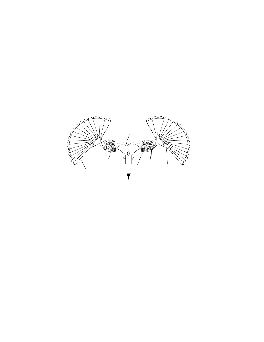
Vision
Flying insects (and arthropods in general) have two large compound eyes
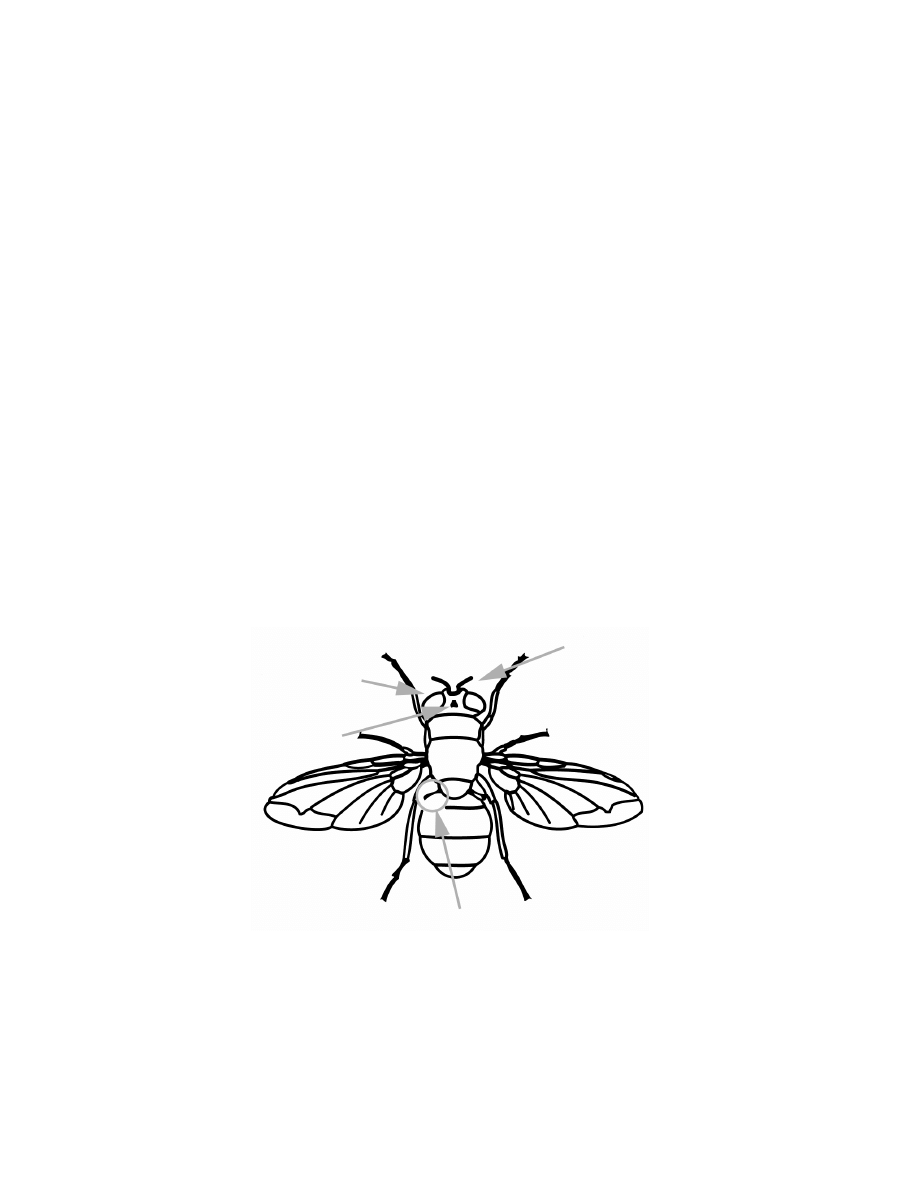
[Chapman, 1998, p. 587] that occupy most of their head (Fig. 3.2). Each
compound eyes
ocelli
halteres
antennas
and hairs
Figure 3.2 The most important perceptive organs related to flight control: the
large compound eyes (and the ocelli), the halteres, and the antennas and hairs.
© 2008, First edition, EPFL Press
Flying Insects
35
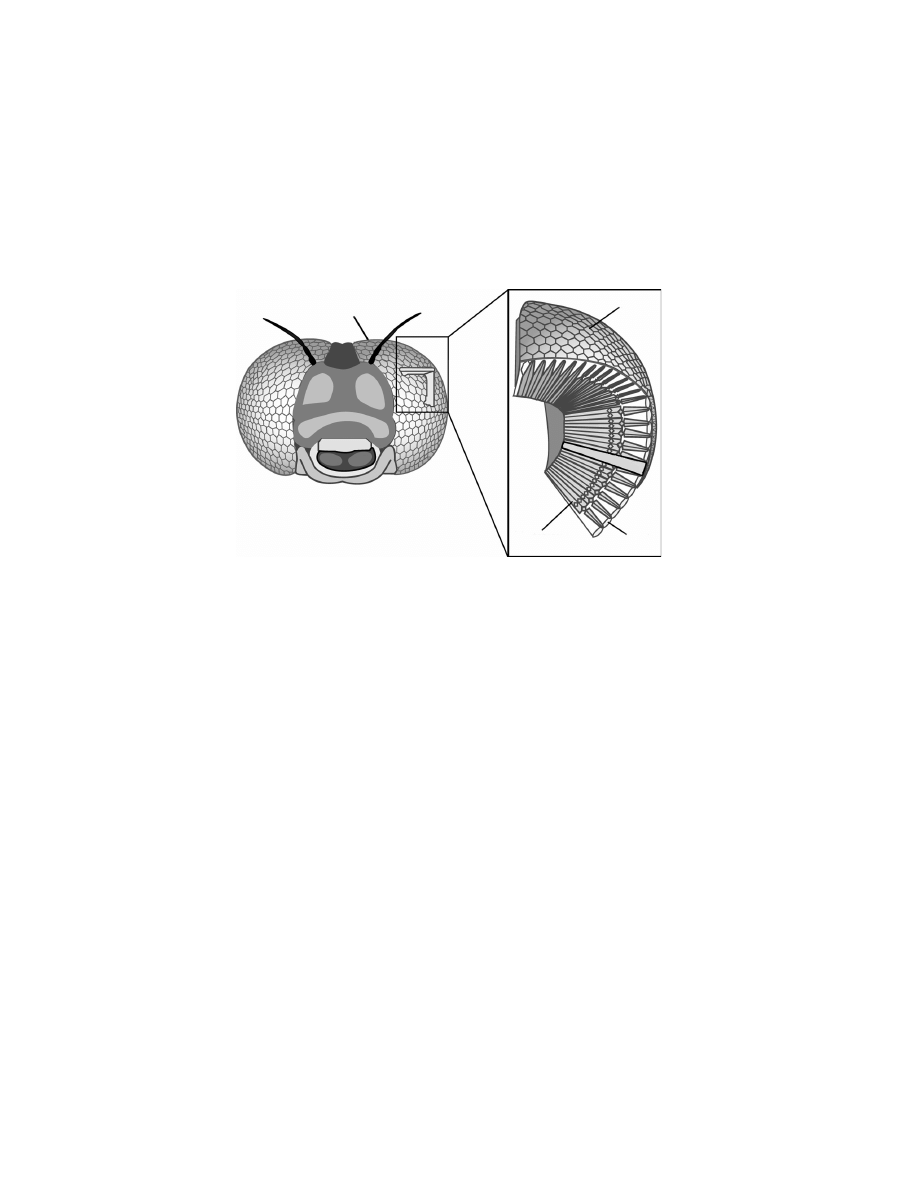
eye is made up of tiny hexagonal lenses, also called facets, that fit together
like the cells of a honeycomb (Fig. 3.3). Each lens admits a small part
of the total scene that the insect visualises. All the parts combine to-
gether and form the whole picture. Underlying the lens is a small tube,
Facet
Facet
Lens
Photoreceptor
ommat
idium
Figure 3.3 The compound eyes of flying insects. The compound eyes are made
up of repeating units, the ommatidia, each of which functions as a separate visual
receptor. Each ommatidium consists of a lens (the front surface of which makes up
a single facet), a transparent crystalline cone, light-sensitive visual cells arranged
in a radial pattern, and pigment cells that separate the ommatidium from its
neighbours.
the ommatidium, containing several photosensitive cells (for details, see
, 1975). For the sake of simplicity, we assume in this book
that one ommatidium corresponds to one viewing direction and thus to
one pixel, although different kinds of compound eyes exist with different
arrangements [Land, 1997]. In insects, the number of ommatidia varies
from about 6 in some worker ants up to 30
0
000 in dragonflies. In Diptera,
this range is smaller and varies from 700 in the fruitfly to 6000 ommatidia
per eye in the blowfly, covering roughly 85% of the visual field (maximum
possible solid angle whose apex is located at the center of the eye). Taking
the square root of the number of ommatidia, the eye of the fruitfly is thus
roughly equivalent to a 26 × 26 pixel array covering one visual hemisphere,
which is much less than in state-of-the-art artificial vision sensors (
© 2008, First edition, EPFL Press
36
Sensor Suite for Flight Control
Human retina (rods)
Human retina (cones)
HDTV resolution; Nikon D1 digital camera
XGA resolution
VGA resolution; Logitech Quickcam Pro digital camera
Dragonfly Anax junius
Blowfly Calliphora erythrocephala
Hausefly Musca domestica
Fruit fly Drosophila melanogaster
Number of pixels
10
8
10
7
10
6
10
5
10
4
10
3
10
2
Figure 3.4 The number of pixels in artificial and biological vision systems (single
eyes). The number of pixels in the eyes of flying insects is orders of magnitude lower
than in current silicon imagers [Harrison, 2000; Land, 1997].
To compare the resolution power of vision systems, one has to consider
not only the number of pixels but also the covered field, or more precisely
the ratio of the field of view (FOV) to the number of pixels. According
to Land [1997], many flying insects have an interommatidial angle in the
range of 1-5
◦
(blowfly: 1.1
◦
, housefly: 2.5
◦
, fruitfly: 5
◦
), and this angle
corresponds to the visual space that a single ommatidia is able to sample
(acceptance angle). The best resolving power achievable by the fly’s eye is
thus 60 times inferior of that of a human eye. However, the compound eye
configuration permits a much wider FOV because of the juxtaposition of
small tubes aimed at divergent orientations instead of a single lens and a
focal plane.
(1)
Indeed, flies can see in almost every direction except in the
blind spot caused by their own body.
It is remarkable that flies are capable of such impressive flight control
when considering the low-resolution of their eyes, which is a consequence
(1)
See [
, 2002] for a nice reconstruction of what flies see.
© 2008, First edition, EPFL Press

Flying Insects
37
of their compound design. Moreover, because of their eye arrangement
they cannot estimate distances from stereo-vision or focus, as outlined by
[Srinivasan et al., 1999]:
Unlike vertebrates, insects have immobile eyes with fixed-focus
optics. Thus, they cannot infer the distance of an object from the
extent to which the directions of gaze must converge to view the
object, or by monitoring the refractive power that is required to
bring the image of the object into focus on the retina. Further-
more, compared with human eyes, the eyes of insects are positioned
much closer together, and possess inferior spatial acuity. There-
fore the precision with which insects could estimate the range of
an object through binocular stereopsis would be much poorer and
restricted to relatively small distances, even if they possessed the
requisite neural apparatus.
However, fly vision greatly exceeds human vision in the temporal domain.
Human vision is sensitive to temporal frequencies up to 20 Hz, whereas
ommatidia respond to temporal frequencies as high as 200-300 Hz [Dudley,
2000, p. 206]. This allows flying insects to be very good at detecting
changes in the visual field and especially
optic flow (see
).
In addition to their compound eyes, numerous insects have three simple
photoreceptors, called
ocelli. These ocelli are set in the form of a triangle
between the compound eyes (
). Since they are unfocused, they
cannot form images. Rather, they are used to measure brightness and are
thought to contribute to the dorsal light response where the fly aligns
its head with sources of brightness [Schuppe and Hengstenberg, 1993].
Therefore, ocelli might be used to provide information about the location
of the horizon in outdoor environments.
3.2.2
Vestibular Sense
In many fast-moving animals inputs from mechanosensory organs (such as
the labyrinth in the ears of vertebrates) contribute to compensatory
reactions, and are generally faster than what can be detected through the
visual system independently of lighting conditions [Nalbach and Heng-
stenberg, 1994]. Diptera possess a remarkable organ for measuring angu-
lar velocities [Chapman, 1998, p.196]. Rotations of their body are per-
© 2008, First edition, EPFL Press

38
Sensor Suite for Flight Control
ceived through the halteres (
, also visible in Figure 3.1a), which
have evolved by the transformation of the hind wings into tiny club-shaped
organs that oscillate during flight in antiphase with the wings [Nalbach,
1993]. These mechanosensors measure angular velocity by sensing the peri-
odic Coriolis forces that act upon the oscillating haltere when the fly rotates
[Hengstenberg, 1991]. Coriolis effects are inertial forces acting on bodies
moving in a non-inertial (rotating) reference frame. The forces measured by
the halteres are proportional to the angular velocity of the fly’s body.
According to Dickinson [1999] haltere feedback has two roles. The first
one is gaze stabilisation:
One important role of the haltere is to stabilize the position of
the head during flight by providing feedback to the neck motor
system. (...) Nalbach and Hengstenberg demonstrated that the
blowfly, Calliphora erythrocephala, discriminates among oscilla-
tions about the yaw, pitch and roll axes and uses this information to
make appropriate compensatory adjustments in head position (...);
[Nalbach, 1993; Nalbach and Hengstenberg, 1994]. Such reflexes
probably act to minimize retinal slip during flight, thereby stabil-
ising the image of the external world and increasing the accuracy
with which the visual system encodes motion.
The second role of the halteres consists in direct flight stabilisation:
Although the role of the haltere in stabilising gaze may be impor-
tant, a more essential and immediate role of the haltere is to pro-
vide rapid feedback to wing-steering muscles to stabilize aerody-
namic force moments.
More recently, gyroscopic sense has also been discovered in insects that do
not possess halteres. Sane
et al. [2007] have shown that the antennas of
wasps could also vibrate and sense Coriolis forces much like the halteres in
Dipteras.
In summary, flight stabilisation in flies – and probably other flying
insects – is ensured by a combination of visual and vestibular senses and
both sensory modalities are of interest for the realisation of artificial systems.
© 2008, First edition, EPFL Press
Flying Insects
39
3.2.3
Airflow Sensing and Other Mechanosensors
Although less thoroughly studied, it is likely that flying insects integrate
information from other perceptive organs to control their flight. One of
those are the bell-shaped campaniform sensilla [Chapman, 1998, p. 195]
that act as strain gauges. About 335 sensilla are indeed located at the haltere
base in order to detect Coriolis forces [Harrison, 2000]. Campaniform
sensilla are also present on the wings allowing a perception of wing load
[Hengstenberg, 1991].
Aerodynamically induced bending in external structures such as anten-
nas potentially provides information concerning the changing speed and di-
rection of flight [Dudley, 2000]. As noted by [Hausen and Egelhaaf, 1989],
antennas are likely to participate in the mechanosensory feedback. Flying
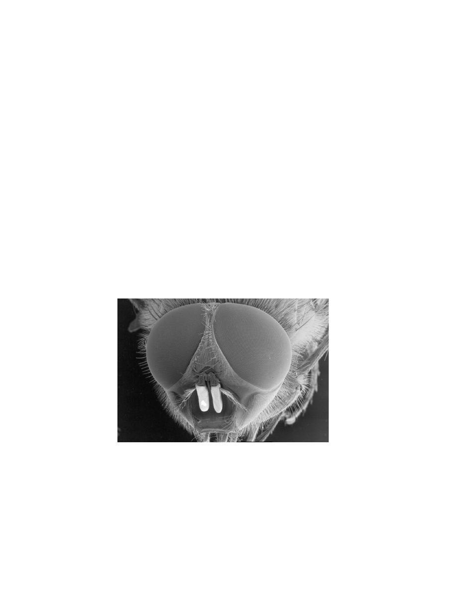
insects are also equipped with a multitude of tiny bristles (Fig. 3.5) that
could help in controlling flight by providing information about air move-
ments and changes in air pressure. In an experiment on the interaction be-
tween vision and haltere feedback, Sherman and Dickinson [2004] noted:
Figure 3.5 The head of a common blowfly. This image shows the hairy nature
of these insects. Copyright of The University of Bath UK and reprinted with
permission.
© 2008, First edition, EPFL Press

40
Information Processing
Posternal hairs on the neck, and wing campaniform sensilla could
contribute to both the basic response to mechanical oscillation and
the attenuation of the visual reflex during concurrent presentation.
As described in his thesis, Harrison [2000] also presumes that flies are able
to estimate linear accelerations through proprioceptive sensors that equip
the legs and neck, and that are able to measure position and strain.
What should be retained from this brief description of other mechano-
sensors that are found all around their body is that insects are very likely
to have a good perception of airflow and thus airspeed. Therefore, it may
be interesting to equip flying robots with airflow sensors, which should not
necessarily be linear.
3.3
Information Processing
Among the sensory modalities that are involved in insect flight control,
visual cues exert a predominant influence on orientation and stability. This
present Section thus focuses on vision processing.
The importance of
vision for flight is underlined by the relative size of the brain region
dedicated to the processing of afferent optical information. The visual sys-
tem of flies has been investigated extensively by means of behavioural ex-
periments and by applying neuroanatomical and electrophysiological tech-
niques. Both the behaviour and its underlying neuronal basis can some-
times be studied quantitatively in the same biological system under similar
stimulus conditions [Krapp, 2000]. Moreover, the neuronal system of flying
insects is far simpler than that of vertebrates, ensuring biologists a better
chance to link behaviour to single neuron activity. The fact that the direct
neuronal chain between the eye and the flight muscles consists of only 6-7
cells [Hausen and Egelhaaf, 1989] further illustrates the simplicity of the
underlying processing. When electrophysiological investigations are not
possible – e.g. because of the small size of some neurons – it is sometimes
still possible to deduce mathematical models of the functioning of neuronal
circuits by recording from downstream neurons.
© 2008, First edition, EPFL Press
Flying Insects
41
3.3.1
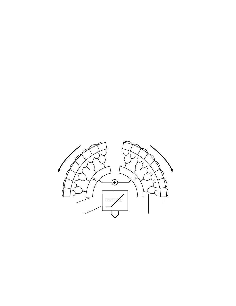
Optic Lobes
The optic lobes (i.e. peripheral parts of the nervous system in the head,
see Figure 3.6) of flies are organised into three aggregates of neurones (also
called ganglia or neuropils): the
lamina, the medulla, and the lobula complex
(lobula and lobula plate), corresponding to three centers of vision process-
ing. The retinotopic
(2)
organisation is maintained through the first two
neuropils down to the third one, the lobula, where a massive spatial inte-
gration occurs and information from very different viewing directions are
pooled together:
Facet (lens)
Ommatidium
Lobula
plate
Medulla
Lamina
Brain
Lobula
To motor centers in the thorax
Figure 3.6 A schematic representation of the fly’s visual and central nervous
system (cross section through the fly’s brain). Photoreceptor signals are transmitted
to the lamina, which accentuates temporal changes. A retinotopic arrangement
is maintained through the medulla. The lobula plate is made up of wide-field,
motion-sensitive tangential neurons that send information to the controlateral
optic lobe as well as to the thoracic ganglia, which control the wings. Adapted
from Strausfeld [1989].
•
The
lamina lies just beneath the receptor layer of the eye and receives
direct input from photoreceptors. The neurons in this ganglion act as
high-pass filters by amplifying temporal changes. They also provide a
gain control functionality thus ensuring a quick adaptation to varia-
(2)
The neighbourhood is respected, i.e. neurons connected to neighbouring ommatidia
are next to each other.
© 2008, First edition, EPFL Press

42
Information Processing
tions in background light intensity. Axons from the lamina invert the
image from front to back while projecting to the medulla.
•
Cells in the
medulla are extremely small and difficult to record from
(see, e.g.
, 1996). However, behavioural exper-
iments suggest that local optic-flow detection occurs at this level (see
Sect. 3.3.2).
The retinotopic organisation is still present in this sec-
ond ganglion and there are about 50 neurons per ommatidium. The
medulla then sends information to the lobula complex.
•
The third optic ganglion, the
lobula complex, is the locus of massive spa-
tial convergence. Information from several thousand photoreceptors,
preprocessed by the two previous ganglia, converges onto a mere 60
cells in the lobula plate [Hausen and Egelhaaf, 1989]. These so-called
tangential cells (or LPTC for Lobular Plate Tangential Cells) have broad
dendritic trees that receive synaptic inputs from large regions of the
medulla, resulting in large visual receptive fields (see
). The
lobula complex projects to higher brain centers and to descending neu-
rons that carry information to motor centers in the thoracic ganglia.
From an engineering perspective, the lamina provides basic functional-
ities of image preprocessing such as temporal and spatial high-pass filtering
as well as an adaptation to background light. Although generally useful,
such functionalities will not be further described nor implemented in our
artificial systems because of the relative visual simplicity of our test envi-
ronments (Sect. 4.4). The two following ganglia, however, are more inter-
esting since they feature typical properties used by flying insects for flight
control. Specificities of the medulla and the lobula will be further described
in the following two Sections.
3.3.2
Local Optic-flow Detection
Although the use of optic flow in insects is widely recognised as the pri-
mary visual cue for in-flight navigation, the neuronal mechanisms under-
lying local motion detection in the medulla remain elusive [Franceschini
et al., 1989; Single et al., 1997]. However, behavioural experiments cou-
pled with recordings from the tangential cells in the lobula have led to
functional models of local motion detection. The one best-known is the
© 2008, First edition, EPFL Press
Flying Insects
43
so-called
correlation-type elementary motion detector (EMD), first proposed by
Hassenstein and Reichardt [1956], in which intensity changes in neigh-
boring ommatidia are correlated [Reichardt, 1961, 1969]. This model was
initially proposed to account for the experimentally observed
optomotor re-
sponse in insects [Götz, 1975]. Such a behaviour tends to stabilise the insect’s
orientation with respect to the environment and is evoked by the apparent
movement of the visual environment.
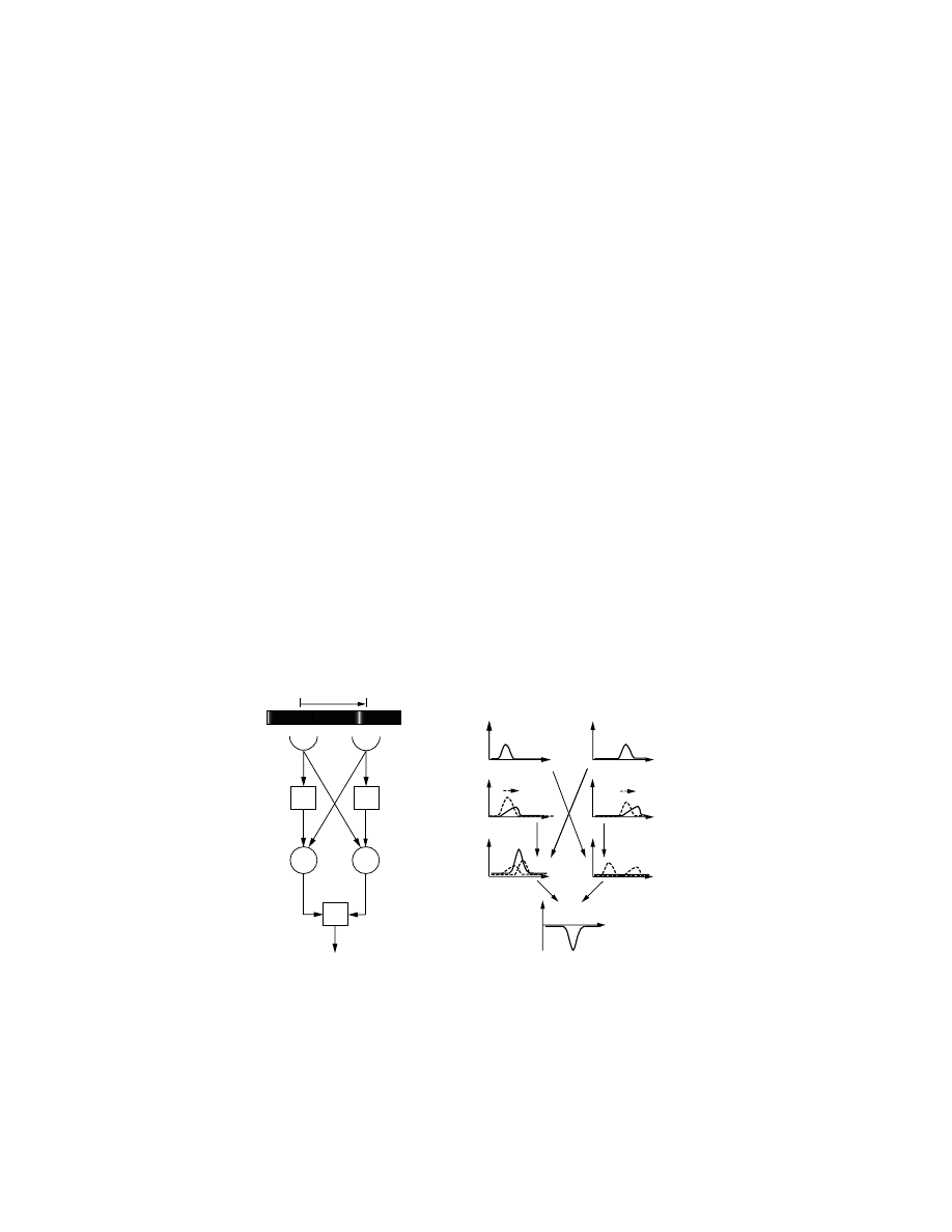
An EMD of the correlation type basically performs a multiplication of
input signals received by two neighbouring photoreceptors (Fig. 3.7). Prior
to entering the multiplication unit, one of the signals is delayed (e.g. using
by a first order low-pass filter), whereas the other remains unaltered. Due
to these operations, the output of each multiplication unit preferentially
responds to visual stimuli moving in one direction. By connecting two
of them with opposite directional sensitivities as excitatory and inhibitory
elements to an integrating output stage, one obtains a bidirectional EMD
(see also
, 1989, for a good review of the EMD principle).
This popular model has been successful at explaining electrophysiological
responses of tangential cells to visual stimuli (see, e.g.
,
1989) and visually-elicited behavioural responses (see, e.g.
, 1990).
D
–S+
D
M
correlation
substraction
M
interommatidia angle
I
1
I
1
I
2
t
t
t
t
t
t
I
2
– +
t
photo-
receptor
temporal
delay
Figure 3.7 The correlation-type elementary motion detector [Reichardt, 1969].
See text for details. Outline adapted from [
, 2003].
© 2008, First edition, EPFL Press
44
Information Processing
On the other hand, it is important to stress that this detector is not
a pure image velocity detector. Indeed, it is sensitive to the contrast fre-
quency of visual stimuli and therefore confounds the angular velocity of
Log angular velocity, V (deg/sec)
Normalised torque response
Normalised torque response
Log temporal frequency (Hz)
(d)
(a)
(b)
(c)
(e)
T
V
V
V
T
T
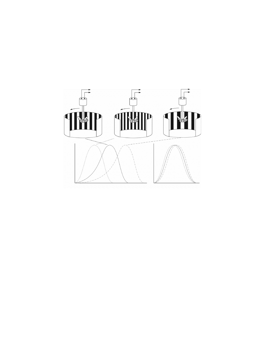
Figure 3.8 The optomotor response of insects [Srinivasan
et al., 1999]. If a flying
insect is suspended in a rotating striped drum, it will attempt to turn in the
direction of the drum’s rotation. The resulting yaw torque is a measure of the
strength of the optomotor response. For stripes of a given angular period (as in
a), the normalised strength of the optomotor response is a bell-shaped function of
the drum’s rotational speed, peaking at a specific angular velocity of rotation (solid
curve, d). If the stripes are made finer (as in b), one obtains a similar bell-shaped
curve, but with the peak shifted toward a lower angular velocity (dashed curve, d).
For coarser stripes (as in c), the peak response occurs at higher angular velocities
(dot-dashed curve, d). However, the normalised response curves coincide with each
other if they are re-plotted to show the variation of response strength with the
temporal frequency of optical stimulation that the moving striped pattern elicits
in the photoreceptors, as illustrated in (e). Thus, the optomotor response that is
elicited by moving striped patterns is tuned to temporal frequency rather than to
angular velocity. Reprinted with permission from Prof. Mandyam V. Srinivasan.
© 2008, First edition, EPFL Press

Flying Insects
45
patterns with their spatial structure [Reichardt, 1969; Egelhaaf and Borst,
1989; Franceschini
et al., 1989; Srinivasan et al., 1999]
(3)
. The correlation-
type EMDs are tuned to temporal frequency, rather than to angular veloc-
ity, as outlined by the summary of the optomotor response experiment in
Although visual motion processing in insects has been studied and
characterised primarily through the optomotor response, alternative tech-
niques have led researchers to contradictory conclusions with regard to lo-
cal motion detection. In the 1980’s, Franceschini and colleagues proposed
a different scheme of local motion detection using lateral facilitation of
a high-pass filtered signal [Franceschini
et al., 1989; Franceschini, 2004].
This was the result of experiments whereby single photoreceptors of the fly
retina were stimulated in sequence while the activity of a specific tangential
cell in the lobula was recorded. The underlying idea was that an intensity
change detected by a photoreceptor yields a slowly (exponentially) decaying
signal that is sampled by an impulse due to the same intensity change when
it hits the neighbouring photoreceptor.
Studies with free-flying bees have identified several other visually elic-
ited behaviours that cannot be explained by the optomotor response and the
correlation-type EMD model. These behaviours are essentially the center-
ing response, the regulation of flight speed, and the landing strategy (see
for further description). All these behaviours appear to be
mediated by a motion detection mechanism that is sensitive primarily to
the speed of the visual stimulus, regardless of its spatial structure or the
contrast frequency that it produces [Srinivasan
et al., 1999]. These findings
are further supported by an experiment with free-flying Drosophila, where
the fruitflies were found to demonstrate a good insensitivity to spatial fre-
quency when keeping ground speed constant by maintaining optic flow at
a preferred value, while presented with various upwind intensities [David,
1982].
A neurobiologically realistic scheme for measuring the angular speed
of an image, independent of its structure or contrast, has been proposed
(3)
However, recent work has shown that for natural scenes, enhanced Reichardt EMDs
can produce more reliable estimates of image velocity [Dror
et al., 2001].
© 2008, First edition, EPFL Press

46
Information Processing
[Srinivasan et al., 1991]. This non-directional model is still hypotheti-
cal, although recent physiological studies have highlighted the existence
of distinct pathways in the optic lobes responsible for directional and non-
directional motion detection [Douglass and Strausfeld, 1996]. Unlike Re-
ichardt’s (correlation-type) and Franceschini’s (facilitate-and-sample) mod-
els, Srinivasan’s model fairly accurately encodes the absolute value of image
velocity but not the direction of motion. Note that non-directional motion
detection is sufficient for some of the above-mentioned behaviours, such as
the centering response.
It is interesting to notice that the Reichardt model is so well estab-
lished that it has been widely used in bio-inspired robotics (e.g. Huber,
1997; Harrison, 2000; Neumann and Bülthoff, 2002; Reiser and Dick-
inson, 2003; Iida, 2003). Nevertheless some notable deviations from it
exist [Weber
et al., 1997; Franz and Chahl, 2002; Ruffier and Franceschini,
2004]. In our case, after preliminary trials with artificial implementation
of correlation-type EMDs, it became clear that more accurate image ve-
locity detection (i.e. independent of image contrast and spatial frequency)
would be needed for the flying robots. We therefore searched for non-
biologically-inspired algorithms producing accurate and directional optic
flow estimates. The image interpolation algorithm (also proposed by Srini-
vasan, see
) was selected. To clearly stress the difference, the term
optic-flow detector (OFD) is used to refer to the implemented scheme for
local motion detection instead of the term EMD. Of course, the fact that
local motion detection is required as a preprocessing stage in flying insects
is widely accepted among biologists and is thus also applied to the bio-
inspired robots presented in this book.
3.3.3
Analysis of Optic-flow Fields
Visual motion stimuli occur when an insect moves in a stationary environ-
ment, and their underlying reason is the continual displacement of retinal
images during self motion. The resulting optic-flow fields depend in a char-
acteristic way on the trajectory followed by the insect and the 3D structure
of the visual surroundings. These motion patterns therefore contain infor-
mation indicating to the insect its own motion and the distances from po-
tential obstacles. However, this information cannot be directly retrieved at
© 2008, First edition, EPFL Press
Flying Insects
47
the local level and optic flow from various regions of the visual field must be
combined in order to infer behaviourally significant information (Fig. 3.9).
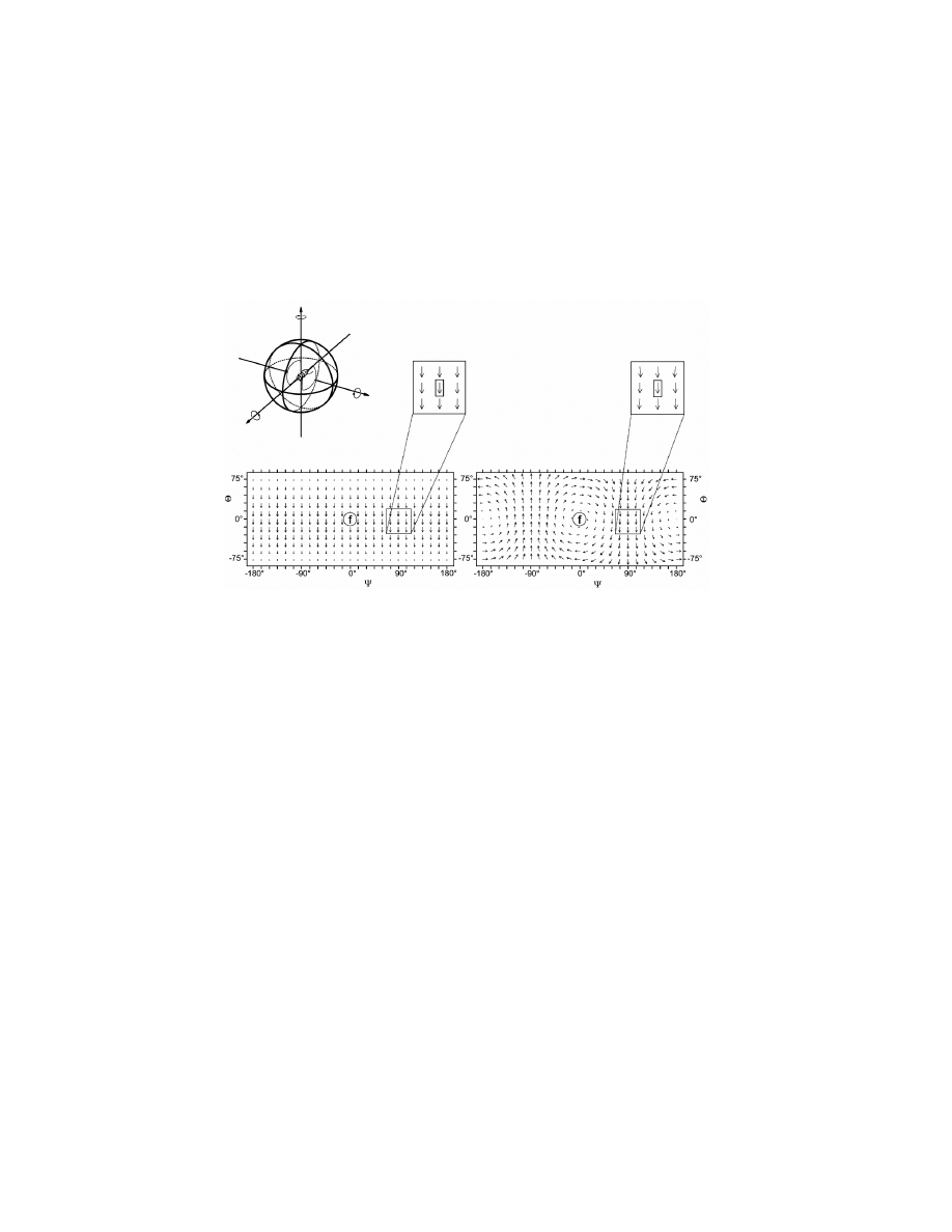
azimuth
elevation
elevation
azimuth
lift translation
roll rotation
(a)
(b)
(c)
yaw
lift
roll
pitch
slip
thrust
Figure 3.9 The global structures of translational and rotational optic-flow fields.
(a) The movements of a fly can be described by their translational (thrust, slip, lift)
and rotational (roll, pitch, yaw) components around the 3 body axes (longitudinal,
transverse, vertical). These different motion components induce various optic-flow
fields over both eyes of the moving insect. For simplicity, equal distances from the
objects in a structured environment are assumed. (b) An optic-flow field caused
by a lift translation. (c) An optic-flow field caused by a roll rotation. Optic-
flow patterns are transformed from the visual unit sphere into Mercator maps to
display the entire visual space using spherical coordinates. The visual directions
are defined by the angles of azimuth and elevation. The encircled f (frontal) denotes
the straight-ahead direction. Globally, the two optic-flow fields can easily be
distinguished from one another. However, this distinction is not possible at the
level of local motion detectors. See, e.g. the optic-flow vectors indicated in the
boxes: local motion detectors at this place would elicit exactly the same response
irrespective of the motion. Reprinted from Krapp
et al. [1998] with permission
from The American Physiological Society.
© 2008, First edition, EPFL Press

48
Information Processing
Analysis of the global motion field (or at least several different regions)
is thus generally required in order for the local measurements to be ex-
ploited at a behavioural level. Some sort of spatial integration is known
to take place after the medulla (where local motion detection occurs retino-
topically), mainly in the lobula plate where tangential neurons receive input
from large receptive fields [Hausen and Egelhaaf, 1989]. The lobula plate
thus represents a major centre for optic-flow field analysis. Some of the 60
neurons of the lobula plate are known to be sensitive to coherent large-field
motion (i.e. the VS, HS and Hx-cells), whereas other neurons, the Figure
detection cells (FD-cells), are sensitive to the relative motion between small
objects and the background [Egelhaaf and Borst, 1993b; Krapp and Heng-
stenberg, 1996]. As an example of the usefulness of these neurons at the
behavioural level, there is sound evidence that HS and VS-cells are part of
the system that compensates for unintended turns of the fly from its course
[Krapp, 2000].
Detection of Self-motion
Quite recently, neuroscientists have analysed the specific organisation of the
receptive fields, i.e. the distribution of local preferred directions and lo-
cal motion sensitivities, of about 30 tangential cells out of the 60 present
in the lobula. They found that the response fields of VS neurons resemble
rotational optic-flow fields that would be induced by the fly during rota-
tions around various horizontal axes [Krapp
et al., 1998]. In contrast to the
global rotational structure of VS cells, the response field of Hx cells have
the global structure of a translational optic-flow field [Krapp and Heng-
stenberg, 1996]. The response fields of HS cells are somewhat more difficult
to interpret since it is believed that they do not discriminate between rota-
tional and translational components [Krapp, 2000]. In summary, it appears
that tangential cells in the lobula act as neuronal matched filters [Wehner,
1987] tuned to particular types of visual wide-field motion (
). It is
also interesting to notice that these receptive-field organisations are highly
reliable at the interindividual level [Krapp
et al., 1998] and seem to be in-
dependent of early sensory experiences of the fly. This suggests that the sen-
sitivity of these cells to optic-flow fields has evolved on a phylogenetic time
scale [Karmeier
et al., 2001].
© 2008, First edition, EPFL Press
Flying Insects
49
Franz and Krapp [2000] experienced a certain success when estimating
self-motion of a simulated agent based on this theory of visual matched
filters. However, Krapp [2000] interprets this model of spatial integration
with caution:
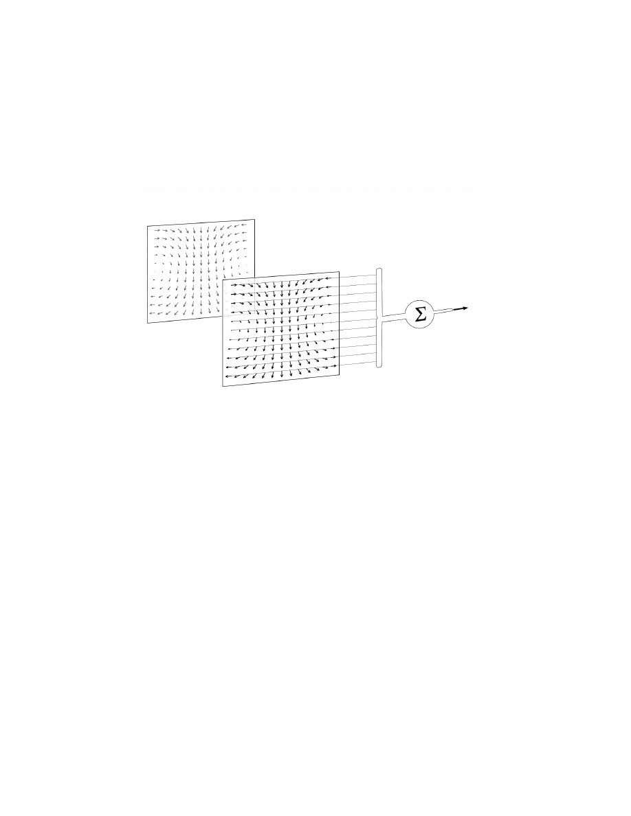
directions of
velocity-vectors of
a specific optic flow
distribution of
preferred directions
of converging EMD'S
thus the ne
uron is
tuned to de
tect a
specific self-
motion
correspond to
Figure 3.10 A hypothetical filter neuron matched to a particular optic-flow field
induced by self-motion (e.g. rotation). Local motions of the optic-flow field locally
activate those motion detectors with appropriate preferred directions. A wide-
field neuron selectively collects and spatially integrates the signals of these motion
detectors. Hence, it would be most sensitive to that particular optic-flow and
consequently to the self-motion that caused the flow. Reprinted from Krapp
et al.
[1998] with permission from The American Physiological Society.
[Some] approaches take for granted that the results of the local mo-
tion estimates are summed up in a linear fashion at an integrating
processing stage. For insect visual systems, however, it was found
that local motion analysis is achieved by elementary motion de-
tectors whose output is not simply proportional to velocity (...)
but also depends on pattern properties like spatial wavelength and
contrast (...). Hence, it remains unclear how biological sensory
systems cope with highly dynamic stimuli as encountered, for in-
stance, by the fly during free flight. It is by no means easy to pre-
dict the signals of the tangential neurons under such natural con-
ditions.
© 2008, First edition, EPFL Press

50
Information Processing
Another problem is that tangential neurons, such as the VS cells, cannot
be expected to be insensitive to optic-flow components induced by move-
ments that are not their own preferred self-motion. The output from those
neurons needs to be corrected for apparent rotations, which may be due to
translational self motions and to rotations around axes other than the pre-
ferred axis. In fact, the use of visual or gyroscopic information for correcting
such errors is a recurrent question which has yet to be resolved. According
to Krapp [2000],
The signals necessary to correct for these erroneous response con-
tributions could be supplied by other wide field neurons.
Or, alternatively:
Correction signals encoding fast self-rotations may also be sup-
plied by the haltere system [Nalbach, 1994]. Because the dynamic
range of the haltere system is shifted toward higher angular veloci-
ties, it is thought to complement the visual self-motion estimation
[Hengstenberg, 1991].
The computational properties of tangential neurons have mainly been char-
acterised in tethered flies with simplistic visual stimuli (e.g. Krapp
et al.,
1998). A recent study where blowflies were presented with behaviourally
relevant visual inputs suggests that responses of tangential cells are very
complex and hard to predict based on the results obtained with simplis-
tic stimuli [Lindemann
et al., 2003]. As explained by Egelhaaf and Kern
[2002], only few experiments with natural stimuli have been performed and
even less in closed-loop situation:
Neuronal responses to complex optic flow as experienced during
unrestrained locomotion can be understood only partly in terms of
the concepts that were established on the basis of experiments done
with conventional motion stimuli. (...) It is difficult to predict
the performance of the system during complex flight manoeuvres,
even when wiring diagrams and responses to simplified optic-flow
stimuli are well established.
© 2008, First edition, EPFL Press

Flying Insects
51
Perception of Approaching Objects
Apart from the widely covered topic of tangential cells in the lobula plate
and their resemblance to matched filters, another model of wide field inte-
gration has been proposed to explain the detection of imminent collision.
Here, the purpose is to estimate the distance from objects or the
time to con-
tact (TTC), rather than to detect self motion. Looming stimuli (expand-
ing images) have long been thought to act as essential visual cues for de-
tecting imminent collisions (see, e.g.
, 1976). When tethered flying
flies encounter a looming stimulus, they extend their forelegs in prepara-
tion for landing. This
landing response has been shown to be triggered by
visual looming cues [Borst and Bahde, 1988]. Experiments demonstrate
that the latency of the landing response is reciprocally dependent on the
spatial frequency content and on the contrast of the pattern, as well as on
the duration of its expansion. Borst and colleagues have proposed a model
based on a spatial integration of correlation-type EMDs (
), which
presents the same kind of dependence on spatial frequency and contrast (see
). Very recently, Tammero and Dickinson [2002b] have shown
that collision avoidance manoeuvres in fruitflies can also be explained by
the perception of image expansion as detected by an array of local motion
detectors (see
).
So far, neurons that extract image expansion from the retinotopic array
of local motion detectors have not been found at the level of the lobula
complex [Egelhaaf and Borst, 1993b]. In the cervical connective (just below
the brain in
), however, cells are known to be sensitive to retinal
image expansion. These neurons, which respond strongly when the insect
approaches an obstacle or a potential landing site, have been proposed to be
part of the neuronal circuit initiating the landing response [Borst, 1990].
Other biologists have proposed similar schemes, although based on
pure TTC and thus without any dependency on contrast or spatial fre-
quency, for explaining the deceleration of flies before landing [Wagner,
1982] or the stretching of their wings in plunging gannets [Lee and Red-
dish, 1981]. From a functional point of view, it would obviously be advan-
tageous to use a strategy that estimates TTC independently of the spatial
structure of the object being approached. Indeed, if the underlying local
optic-flow detection is a true image velocity detection, the measure of the
© 2008, First edition, EPFL Press

52
In-Flight Behaviours
TTC can be directly extracted from optic-flow measurements [Poggio
et al.,
1991; Ancona and Poggio, 1993; Camus, 1995].
In summary, individual cells (either in the lobula or in the cervical con-
nective) receive inputs from many local motion detectors and generate out-
put signals that appear to be tuned to estimate particular features of the
global optic-flow field that flying insects experience during flight. Spatial
integration of local optic-flow vectors is thus a necessary operation to pro-
vide useful information for several behaviours such as stabilisation, land-
ing, collision avoidance, etc. Although the weight limitations of the flying
platforms do not permit the presence of as many local motion detectors as
in flying insects, some kind of spatial integration (e.g. combining signals
from left and right OFDs) is used to detect typical patterns of optic flow.
3.4
In-Flight Behaviours
As previously described, flying insects use visual motion and mechanos-
ensors to gain information on the 3D layout of the environment and the
rate of self-motion in order to control their behaviours. In this Section, a set
of basic behaviours is reviewed and linked to possible underlying informa-
tion processing strategies presented in the previous Section. This restricted
palette of behaviours is not a representative sample of the biological liter-
ature, but rather a minimal set of control mechanisms that would allow a
flying system to remain airborne in a confined environment.
3.4.1
Attitude Control
One of the primary requirements for a flying system is to be able to con-
trol its
attitude in order to stay upright or bank by the right amount during
turns [Horridge, 1997]. The attitude of an aerial system is defined by its
pitch and roll angles (
). The so-called
passive stability encompasses
simple mechanisms providing flight stability without active control. For
instance, the fact that insect wings are inserted above the center of grav-
ity provides some degree of passive stability around the roll axis [Chapman,
1998, p. 214]. Other aerodynamic characteristics of the insect body provide
partial compensation for unintended pitch torques [Dudley, 2000, p. 203].
© 2008, First edition, EPFL Press

Flying Insects
53
However, in small flapping-wing insects relying on unsteady-state aerody-
namics
(4)
, such passive mechanisms can compensate only for a small subset
of unintentional rotations.
Insects thus require other mechanisms for attitude control. One such
mechanism is the so-called
dorsal light response [Schuppe and Hengstenberg,
1993] by which insects attempt to balance the level of light received in each
of their three ocelli (see
). This response is believed to help insects
keep their attitude aligned with the horizon [Dudley, 2000, p. 212]. Such
mechanisms have been proposed for attitude control in simulated flying
agents [Neumann and Bülthoff, 2002]. However, this approach is not viable
in indoor environments, since there exits no horizon nor a well defined
vertical light gradient. If insects could control their attitude exclusively
by means of a dorsal light response, they would demonstrate a tendency
to fly at unusual angles when flying among obstacles that partially occlude
light sources. The fact that this does not occur indicates the importance of
other stimuli, although they are not yet fully understood [Chapman, 1998,
p. 216].
It is probable that optic flow (see
) provides efficient cues for
pitch and roll stabilisation in a functionally similar manner to the optomo-
tor response (primarily studied for rotations around the yaw axis). However,
optic flow depends on the angular rate and not on absolute angles. Angular
rates must be integrated over time to produce absolute angles, but integra-
tion of noisy rate sensors results in significant drift over time. Therefore,
such mechanisms fail to provide reliable information with respect to the at-
titude. The same holds true for the halteres (see
), which are also
known to help at regulating pitch and roll velocities but are not able to pro-
vide an absolute reference over long periods of time.
In artificial systems, such as aircraft relying on steady-state aerodynam-
ics, passive stabilisation mechanisms are often sufficient in providing com-
pensation torques to progressively eliminate unintended pitch and roll. For
instance, a positive angle between the left and right wings (called dihedral,
see
for further details) helps in maintaining the wings hori-
zontal, whereas a low center of gravity and/or a well-studied tail geometry
(4)
Direction, geometry and velocity of airflow change over short time intervals.
© 2008, First edition, EPFL Press

54
In-Flight Behaviours
provides good pitch stability
(5)
. The aircraft described later on in this book
operate within the range of steady-state aerodynamics and therefore do not
need an active attitude control, such as the dorsal light response.
3.4.2
Course (and Gaze) Stabilisation
Maintaining a stable flight trajectory is not only useful when travelling from
one point to another, but it also facilitates depth perception, as pointed out
by Krapp [2000]:
Rotatory self-motion components are inevitable consequences of
locomotion. The resulting optic-flow component, however, does
not contain any information about the 3D layout of the environ-
ment. This information is only present within translational optic-
flow fields. Thus for all kinds of long-range and short-range dis-
tance estimation tasks, a pure translatory optic-flow field is desir-
able [Srinivasan
et al., 1996, (...)]. One possibility to, at least, re-
duce the rotatory component in the optic-flow is to compensate for
it by means of stabilising head movements and steering manoeu-
vres. These measures can be observed in the fly but also in other
visually oriented animals, including humans.
The well-known optomotor response (introduced in Section 3.3.2), which
is evoked by the apparent movement of the visual environment, tends to
minimise image rotation during flight and helps the insect to maintain
a straight course [Srinivasan
et al., 1999]. Hence, course stabilisation of
flying insects relies essentially on the evaluation of the optic-flow patterns
perceived during flight and reviewed in Section 3.3.3. Haltere feedback is
also known to play an important role in course stabilisation as well as in
gaze or head
(6)
orientation. As suggested in Krapp’s statement, a rapid head
compensation aids in cancelling rotational optic-flow before the rest of the
body has time to react (see also
, 1991). For instance, in the
(5)
Note however, that rotorcrafts are far less passively stable than airplanes and active
attitude control is a delicate issue because propriocetive sensors like inclinometers
are perturbed by centripetal accelerations during manoeuvres.
(6)
In this context, gaze and head control have the same meaning as a result of insect
eyes being mostly solidly attached to the head.
© 2008, First edition, EPFL Press

Flying Insects
55
free-flying blowfly the angular velocities of the head are approximately half
those of the thorax during straight flight [van Hateren and Schilstra, 1999].
The integration of visual and gyroscopic senses for course and gaze
stabilisation in flying insects seems intricate and is not yet fully understood.
Chan
et al. [1998] have shown that motoneurons innervating the muscles
of the haltere receive strong excitatory input from visual interneurons such
that visually guided flight manoeuvres may be mediated in part by efferent
modulation of hard-wired equilibrium reflexes. Sherman and Dickinson
[2004] have proposed a stabilisation model where sensory inputs from the
halteres and the visual system are combined in a weighted sum. What is
better understood, though, is that fast rotations are predominantly detected
and controlled by mechanosensory systems whereas slow drifts and steady
misalignments are perceived visually [Hengstenberg, 1991].
Whatever the sensory modality used to implement it, course stabilisa-
tion is clearly an important mechanism in visually guided flying systems.
On the one hand, it enables counteractions to unwanted deviations due to
turbulences. On the other hand, it provides the visual system with less in-
tricate optic-flow fields (i.e. exempt of rotational components), hence facil-
itating depth perception, and eventually collision avoidance.
3.4.3
Collision Avoidance
As seen in Section 3.3.3, a trajectory aiming at a textured object or sur-
face would generate strong looming cues, which can serve as imminent
collision warnings. Various authors have shown that the deceleration and
extension of the legs in preparation for landing are triggered by large-
field, movement-detecting mechanisms that sense an expansion of the im-
age [Borst and Bahde, 1988; Wagner, 1982; Fernandez Perez de Talens and
Ferretti, 1975]. Instead of extending their legs for landing, flying insects
could decide to turn away from the looming object in order to avoid it.
This subject has been recently studied by Tammero and Dickinson
[2002a]. The flight trajectories of many fly species consist of straight flight
sequences
(7)
interspersed with rapid changes in heading known as
saccades
(7)
During which the course stabilisation mechanisms described above are probably in
action.
© 2008, First edition, EPFL Press
56
In-Flight Behaviours
[Collett and Land, 1975; Wagner, 1986; Schilstra and van Hateren, 1999].
Tammero and Dickinson [2002a] have reconstructed the optic flow seen by
free-flying Drosophila. Based on the recorded data, they proposed a model
of saccade initiation using the detection of visual expansion, a hypothe-
sis that is consistent with the open-loop presentation of expanding stim-
uli to tethered flies [Borst, 1990]. Although differences in the latency of
the collision-avoidance reaction with respect to the landing response sug-
gest that the two behaviours are mediated by separate neuronal pathways
[Tammero and Dickinson, 2002b], the STIM model proposed by Borst
[1990] and reprinted in Figure 3.11 represents a good understanding of
the underlying principle. Several implementations of artificial systems ca-
pable of avoiding collisions have been carried out using a variant of this
model.The artificial implementation that was the most closely inspired by
the experiments of Tammero and Dickinson [2002a] was developed in the
same laboratory (Reiser and Dickinson, 2003, see also
).
Retina
Movement detectors
Temporal integrator
Spatial integrator
Landing!
Figure 3.11 The so-called STIM (spatio-temporal integration of motion) model
underlying the landing response of the fly [Borst and Bahde, 1988]. The output of
directionally selective correlation-type movement detectors are pooled from each
eye. These large-field units feed into a temporal leaky integrator. Whenever the in-
tegrated signal reaches a fixed threshold, landing is released and a preprogrammed
leg motor sequence is performed to avoid crash-landing.
© 2008, First edition, EPFL Press

Flying Insects
57
3.4.4
Altitude Control
Altitude control is a mechanism that has rarely been directly studied in
insects. However, it obviously represents an important mechanism for
roboticists with respect to the building of autonomous flying machines. In
this Section, we thus consider related behaviours in flying insects that help
to understand how an aerial system could regulate its altitude by using vi-
sual motion cues. These behaviours – especially studied in honeybees – are
the centering response, the regulation of the flight speed, and the grazing
landing.
Bees flying through a narrow gap or tunnel have been shown to main-
tain equidistance to the flanking walls (centering response) by balancing
the apparent speeds of the retinal images on either side [Srinivasan
et al.,
1996, 1997]. The experiments reported by Srinivasan
et al. [1991] unequiv-
ocally demonstrate that flying bees estimate lateral distances from surfaces
in terms of apparent motion of their images irrespective of their spatial fre-
quency or contrast.
In another set of experiments [Srinivasan
et al., 1996, 1997; Srinivasan,
2000], the speed of flying bees has been shown to be controlled by main-
taining a constant optic flow in the lateral regions of the two eyes. This
arguably avoids potential collisions by ensuring that the insect slows down
when flying through narrow passages.
The grazing landing (as opposed to the landing response described in
Section 3.4.3) describes how bees execute a smooth touchdown on horizon-
tal surfaces [Srinivasan
et al., 1997, 2000]. In this situation, looming cues
are weak as a result of the landing surface being almost parallel to the flight
direction. In this case, bees have been shown to hold the image velocity of
the surface in the ventral part of their eyes constant as they approach it, thus
automatically ensuring that the flight speed is close to zero at touchdown.
These three behaviours clearly demonstrate the ability of flying insects
to regulate self-motion using translational optic-flow. The advantage of
such strategies is that the control is achieved by a very simple process
that does not require explicit knowledge of the distance from the surfaces
[Srinivasan and Zhang, 2000].
© 2008, First edition, EPFL Press

58
Conclusion
Observation of migrating locusts have shown that these animals tend
to maintain the optic flow experienced in the ventral part of their eyes con-
stant [Kennedy, 1951]. This ventral optic flow is proportional to the ratio
between forward speed and altitude. Taking inspiration from these obser-
vations, Ruffier and Franceschini [2003] proposed an altitude control sys-
tem, an optic-flow regulator, that keeps the ventral optic flow at a reference
value. At a given ground speed, maintaining the ventral optic flow con-
stant leads to level flight at a given height. If the forward speed happens
to decrease (deliberately or as a consequence of wind), the optic flow regu-
lator produces a decrease in altitude. This optic-flow regulator was imple-
mented on a tethered helicopter and demonstrated an efficient altitude con-
trol and terrain following. Ruffier and Franceschini [2004] also showed that
the same strategy could generate automatic takeoff and landing, and suit-
able descent or ascent in the presence of wind [Franceschini
et al., 2007], as
actually observed in migrating locusts [Kennedy, 1951].
One of the major problems of such strategies lies, once again, in the per-
turbation of the translational flow field by rotational components. In partic-
ular, every attitude correction will result in rotation around the pitch or roll
axes and indeed create a rotational optic flow. Hence, a system correcting
for these spurious signals is required. In flying insects, this seems to be the
role of gaze stabilisation (described in Section 3.4.2). In artificial systems,
the vision system could be actively controlled so as to remain vertical (this
solution was adopted in Ruffier and Franceschini, 2004). However, such a
mechanism requires a means of measuring attitude angles in a non-inertial
frame, which is a non-trivial task. Another solution consists of measuring
angular rates with an inertial system (rate gyro) and directly subtracting ro-
tational components from the global optic-flow field (derotation).
3.5
Conclusion
Attitude control (see
) in insects is believed to be required in or-
der to provide a stable reference for using vision during motion [Horridge,
1997]; and in turn, vision seems to be the primary cue for controlling atti-
tude. The same holds true for course stabilisation (see
), whereby
© 2008, First edition, EPFL Press

Flying Insects
59
straight trajectories allow for the cancellation of rotational optic flow and an
easier interpretation of optic flow for distance estimation. This shows, once
again, that perception, information processing, and behaviour are tightly
interconnected and organised into a loop where adequate behaviour is not
only needed for navigation (and, more generally, survival), but also repre-
sents a prerequisite for an efficient perception and information processing.
This idea is equally highlighted by biologists like Egelhaaf
et al. [2002]:
Evolution has shaped the fly nervous system to solve efficiently and
parsimoniously those computational tasks that are relevant to the
survival of the species. In this way animals with even tiny brains
are often capable of performing extraordinarily well in specific be-
havioural contexts.
Therefore, when taking inspiration from biology, it is worth perceiving
these different levels as tightly connected to each other, rather than trying
to design artificial systems behaving like animals while featuring highly
precise, Cartesian sensors, or, contrarily, creating robots with biomorphic
sensors for cognitive tasks. Following this trend, our approach to robot
design will take inspiration from flying insects at the following three levels:
•
Perception. The choice of sensor modalities is largely based on those of
flying insects (
). Only low-resolution vision, gyroscopic and
airflow information will be fed to the control system.
•
Information processing. In the experiments described in
, the
manner of processing information is largely inspired by what has been
described above. Visual input is first preprocessed with an algorithm
producing local optic-flow estimates (
), which are then spa-
tially integrated and combined with gyroscopic information in order
to provide the control system with meaningful information.
•
Behaviour. Based on this preprocessed information, the control system
is then designed to loosely reproduce the insect behaviours presented
in Section 3.4, which are tuned to the choice of sensors and process-
ing. The resulting system will provide the robots with the basic naviga-
tional capability of moving around autonomously while avoiding col-
lisions.
© 2008, First edition, EPFL Press
Document Outline
- Table of Contents
- CHAPTER 3: Flying Insects
Wyszukiwarka
Podobne podstrony:
ef6684 c006
ef6684 bibliography
ef6684 c007
DK3171 C003
ef6684 c001
ef6684 c002
ef6684 c008
ef6684 c000
ef6684 c005
ef6684 c004
ef6684 c006
ef6684 bibliography
więcej podobnych podstron