PROJECTS
MICROCONTROLLERS
56
elektor - 1/2009
ATM18 on the Air
Connecting up
the RFM12 radio module
Wolfgang Rudolph & Burkhard Kainka (Germany)
Radio technology is fascinating: the almost ghostly ‘action at a distance’ that it allows would in former
times have been regarded as magic or witchcraft. In this article we describe a low-cost yet reliable radio
module that can be used with the ATM18 test system to build remote control and remote data capture
applications.
What would the people of 1800 think if
we could take today’s radio technology
back in time and show it to them? Per-
haps it is for the best that time travel
does not exist, as without a doubt they
would find it entirely beyond their
comprehension and our time travellers
might not prove popular visitors.
The earliest radio communications
were made using sparks. In 1864
James Clerk Maxwell had predicted
the possibility of the existence of
radio waves from theoretical consid-
erations, and just 24 years later, in
1888, Heinrich Rudolf Hertz demon-
strated the production of radio waves
experimentally. He used a spark gap
to create a broad-spectrum radio sig-
nal and was able to receive compo-
nents of it a short distance away from
the transmitter using a loop of wire
and another spark gap. It was another
twelve years before the first example
of message communication by radio:
in 1896 Guglielmo Marconi produced
electromagnetic waves using a spark
gap transmitter and a receiver by Alex-
ander Stepanovich Popov. These early
experiments achieved a range, incred-
ible at the time, of 5 km. This is con-
siderably more than the maximum
range of the author’s first home-made
transistorised FM transmitter, built in
1970, although that did not diminish
his sense of achievement at the time.
Indeed, that was the beginning of his
life-long fascination with radio (which
included the acquisition of an Amateur
Radio licence to put his experiments on
the right side of the law!).
These days it is very simple to commu-
nicate between remote devices using
RFM12S
IC
1
PD4_XCK_T0
GND
ATM18
RFM12
VCC
PB6_XTAL1
PB7_XTAL2
PD6_OC0A_AIN0
PD5_OC0B
080852 - 11
PD7_AIN1
PB0_ICP1
PB1_OC1A
PB2_SS-OC1B
GND_ISP
PC6_RESET
PB3_MOSI
PB4_MISO
PB5_SCK
7
8
16
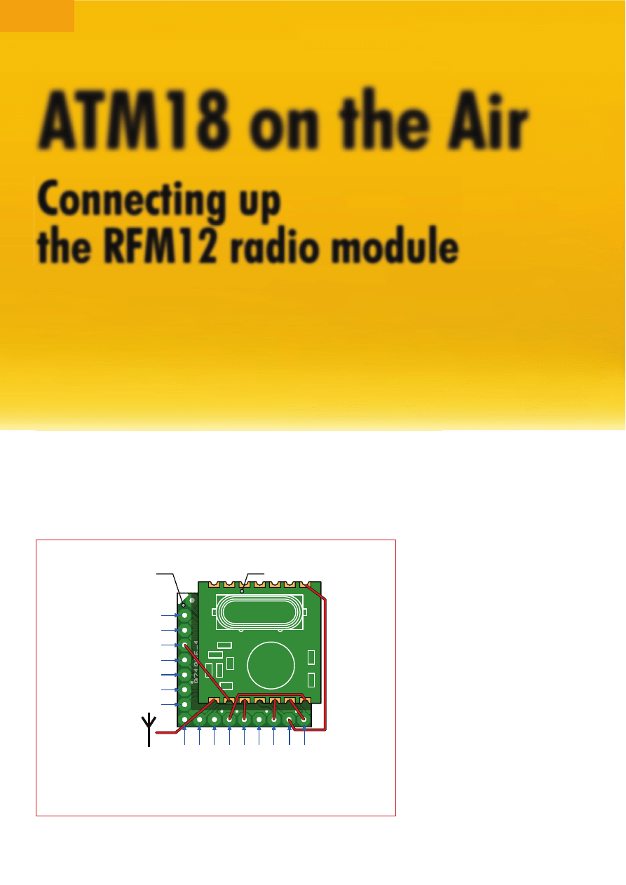
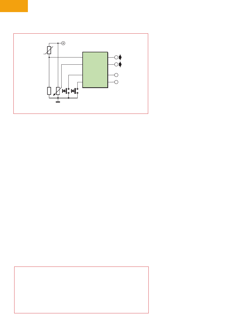
Figure 1. Connecting the RFM12 radio module to the ATM18 microcontroller module.
57
1/2009 - elektor
radio. Even computers, which once
were invariably connected together
using wires, have been affected by the
wireless revolution: Bluetooth, WiFi,
ZigBee and many other technologies
have become standardised. Until now
our tiny ATM18 microcontroller has
been left out: an omission which we
will definitively correct in this article.
ATM18 and RFM12
There is a range of easy-to-use low-
cost radio modules on the market.
We have selected a unit which com-
bines transmitter and receiver on
a single printed circuit board and
which requires no external circuitry.
It is capable of operating alternately
in transmit and receive modes, and
works in the 868 MHz band. Because
more stringent restrictions are placed
on operation in this band than in the
433 MHz band, more reliable operation
is possible with less interference.
The part number of the module is
RFM12. Its frequency of operation
is 868.3 MHz and a duty cycle of at
most 1 % is allowed, and the unit has
a maximum transmit power of around
2.5 mW. It is important to ensure that
these restrictions are complied with,
and that other users do not suffer inter-
ference: in such cases the transmitter
must be switched off immediately and
a different frequency used.
The 1 % duty cycle limit allows us to
use only short data packets; however,
even just one byte is enough to con-
trol eight remote devices. The data
transmission speed is high enough
to allow remote measurement data
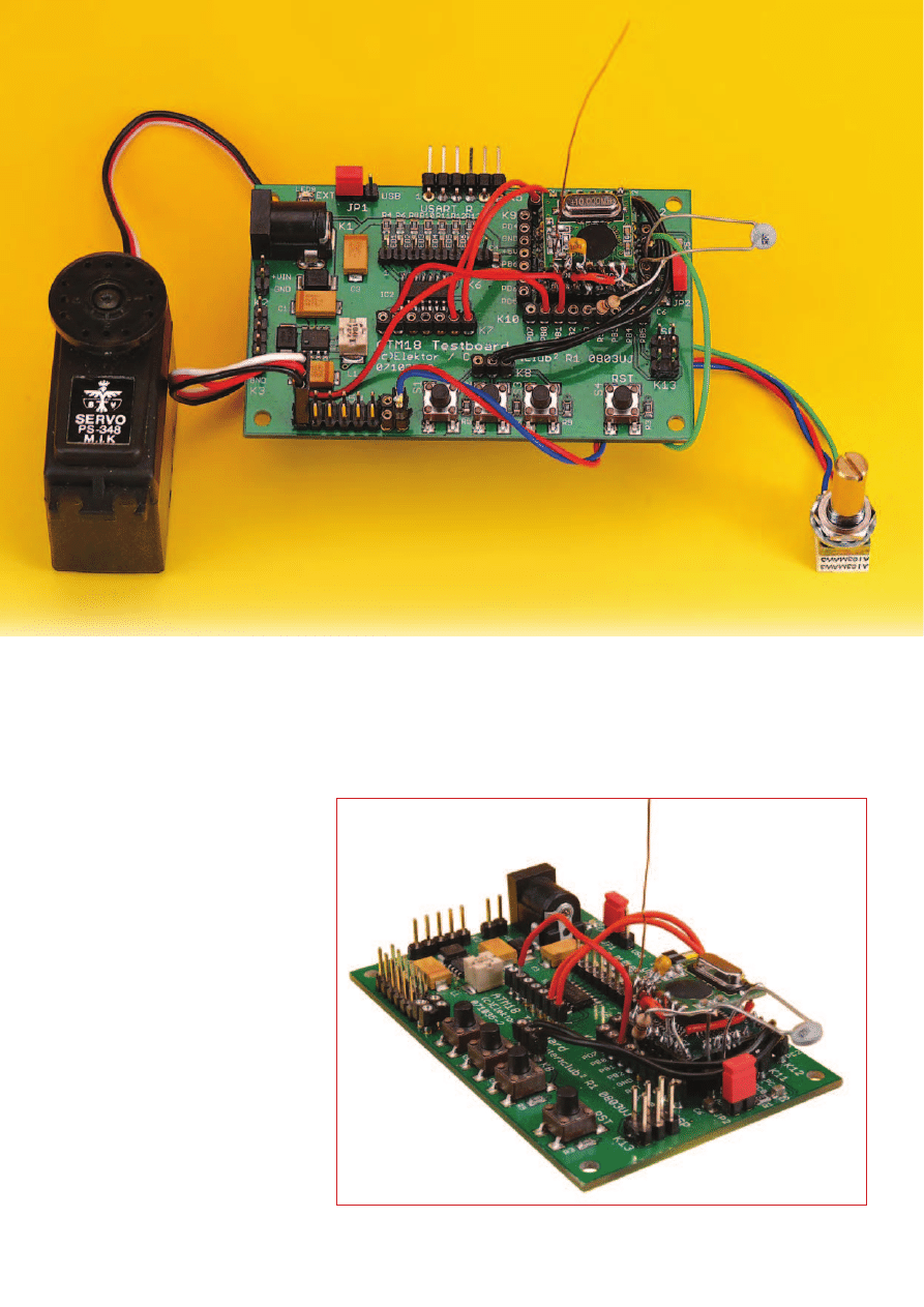
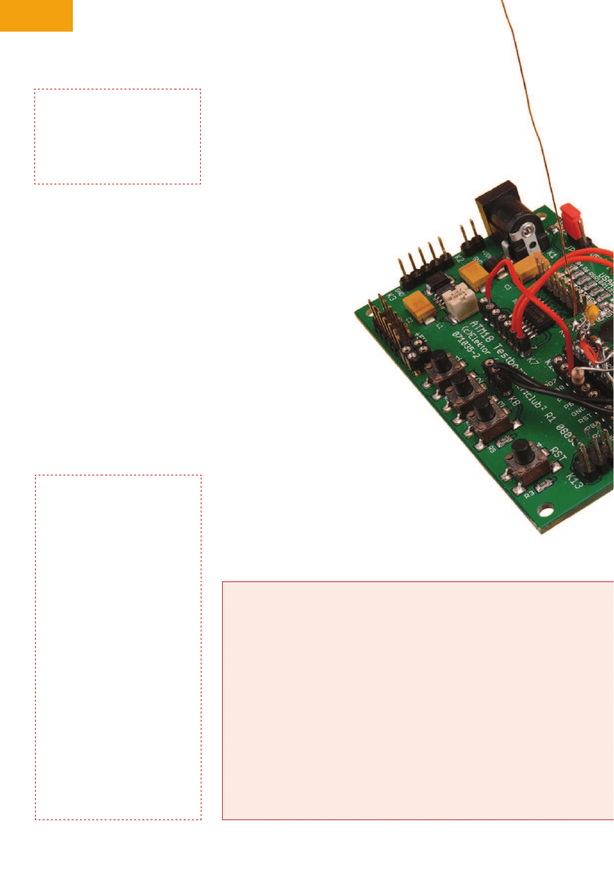
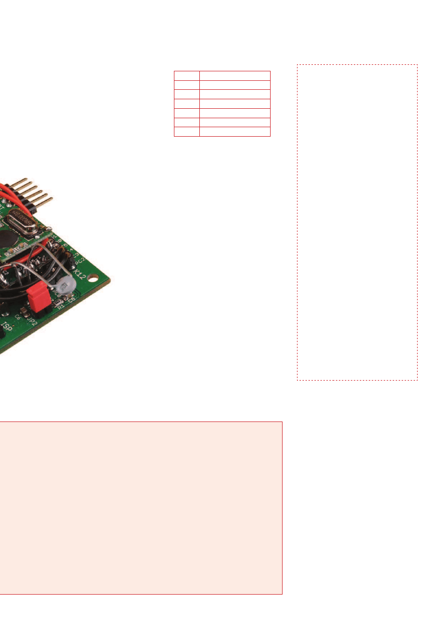
Figure 2. Prototype showing radio and microcontroller modules.
PROJECTS
MICROCONTROLLERS
58
elektor - 1/2009
to be communicated or, for example,
for simultaneous control of the actua-
tors of a robot and read-back of sen-
sor data.
Data communication using the RFM12
is covered in the article on the module
elsewhere in this issue, as are details
of the module’s pinout. When connect-
ing to the ATM18 board the follow-
ing pins on the ATMega88 should be
used:
NSEL to PB2
SDI to PB3
SDO to PB4
SEK to PB5
The radio module can be connected
to the ATM18 controller module using
short lengths of wire. Figure 1 shows
the required connections and Figure 2
ADC7 (two bytes)
Further bytes are needed
i n t h e
data packet to ensure
reli-
able communication. The
bytes in the data payload
is received by the other sys-
tem
which then sends
t h e m o u t a t
19200 baud
over the
serial
inter-
face,
a n d s o i t
is possible to
connect a PC
to the receiving
ATM18 test board
(itself remote from the
transmitting ATM18 test
shows our prototype: a compact micro-
controller unit with radio capability. For
the antenna an 8.5 cm length of wire is
required.
Example application
An important goal for us was to use
the transceiver module to extend
the ATM18 project and broaden the
range of possible applications. A sim-
ple skeleton program provides for the
exchange of data packets: for example,
unit A transmits ten bytes to unit B and
then unit B in turn transmits ten bytes
back to unit A. Such a data exchange
might take place every second.
For one example we wanted to
control a servo and read ana-
logue data. This required two
test boards, two microcon-
troller boards and two trans-
ceivers. The same program runs
on each of the two systems. Infor-
mation available to one unit is made
available almost immediately to the
other unit for further processing.
For example, when a button is pressed
on test board A, a LED or relay can be
activated or deactivated on test board
B. The data from two analogue chan-
nels are also transmitted at the same
time. This requires a total of five bytes
in each data packet, obtained from the
following ports:
Input ports PC2 to PC5 (first byte)
ADC6 (two bytes)
Listing 1
Control pins for the RFM12
Nsel Alias Portb.2
Sdi Alias Portb.3
Sdo Alias Portb.4
Sck Alias Portb.5
Listing 2
Transmitting data
Data_out(1) = 27
Checksum = 27
Data_out(2) = Pinc
Checksum = Checks-
um + Data_out(2)
Dat = Getadc(6)
Hi = High(dat)
Data_out(3) = Hi
Checksum = Checksum + Hi
Lo = Low(dat)
Checksum = Checksum + Lo
Data_out(4) = Lo
Dat = Getadc(7)
Hi = High(dat)
Data_out(5) = Hi
Checksum = Checksum + Hi
Lo = Low(dat)
Checksum = Checksum + Lo
Data_out(6) = Lo
Data_out(7) = Checksum
Send_rfm12
Enable Inter-
rupts ‘Servo
Waitms 500
Disable Interrupts
The basics of ISM
The ISM (Industrial, Scientific and Medical)
bands are radio frequency ranges freely
available for industrial, scientific and me-
dial applications, although there are also
many devices aimed a private users that
operate in these bands. ISM devices require
only general type approval and no indivi-
dual testing, and there are no fees for using
the bands.
The radio communication sector of the In-
ternational Telecommunication Union (ITU-
R) defines the ISM bands at an international
level. WiFi and Bluetooth operate in ISM
bands, as do many radio headphones and
remote cameras, although these are not
usually described as ISM devices. These de-
vices are responsible for considerable inter-
ference to radio communications, especial-
ly in the 70 cm and 13 cm bands (i.e., at
433 MHz and at 2.4 GHz).
ITU-R defines the following bands, not all of
which are available in every country:
6.765 to 6.795 MHz
13.553 to 13.567 MHz
26.957 to 27.283 MHz
40.66 to 40.70 MHz
433.05 to 434.79 MHz
902 to 928 MHz
2.400 to 2.500 GHz
5.725 to 5.875 GHz
24 to 24.25 GHz
59
1/2009 - elektor
board) to acquire and display the
received data and possibly carry out
further processing. The received data
can also be read from the microcontrol-
ler’s ports as follows:
Digital outputs: port D, outputs D2 to
D5
Analogue 1: PWM output on OC1A
Analogue 2: servo pulses on PB0
A terminal emulator will always dis-
play groups of three values, one byte
for the port status and two words
for the analogue channels. For
example, the data might
appear as follows:
63
512
1000
When configuring
the skeleton pro-
gram to drive
t h e r a d i o
module it
is impor-
tant to spec-
ify the SPI bus
pins that are used:
as can be seen from List-
ing 1, the SPI bus uses pins
B2 to B5.
The data packet is framed by a start
byte (27 decimal) and a checksum.
This allows the receiver to detect
reception errors. A typical message
therefore appears as follows:
27
Start byte
63
Port state
1
ADC6 high byte
251
ADC6 low byte
1
ADC7 high byte
252
ADC7 low byte
83
Checksum
Listing 2 shows how a data packet is
sent. An array Data_out is filled with
the required data and then Send_
rfm12 is called. The checksum is cal-
culated as the sum of all the data
bytes including the start byte (27).
The checksum is only one byte long
and so any carries out of this byte
are lost: this is equivalent to logically
ANDing the sum with 255.
Listing 3 shows how a data packet is
received and processed.
The total time available is divided
among the various tasks that are to
be performed.
Transmit: approximately 10 ms
Wait and generate servo pulses:
500 ms
Receive: normally 200 ms, timeout
400 ms to 1400 ms
Wait and generate servo pulses:
700 ms
However, if the two microcontrollers
are transmitting asynchronously (as
will invariably occur) it can happen
that they transmit simultaneously
with the result that neither receives
the other’s message. The problem
then is to arrange things so that as
many transmissions as possible are
received successfully; unfortunately
this requires considerable program-
ming effort as well as the develop-
ment of a suitable underlying protocol.
Things are simplified if it is not essen-
tial that every packet be received
successfully, as we can simply set
the two time delays in the program
to different values. After the success-
ful reception of a data packet the pro-
gram waits for 700 ms before trans-
mitting. After transmission there is a
delay of 500 ms before the receiver is
enabled. The receiver then waits for
at least 200 ms and at most 1400 ms
for a signal from the other unit. In nor-
mal situations this process ensures
that the two stations will synchro-
nise with one another. If something
goes wrong, or if the two units are not
started up at exactly the same time, it
Listing 3
Receiving and processing data
For N
= 1 To 10
Data_in(n) = 0
Next N
Timeout = 400 + Rnd(1000)
Receive_rfm12
If Data_in(1) = 27 Then
Checksum = 27
For N = 2 To 6
Checksum = Checks-
um + Data_in(n)
Next N
If Data_in(7)
= Checksum Then
Checksum = 27
Portd = Data_in(2)
Print Data_in(2)
Dat = 256
* Data_in(3)
Dat = Dat
+ Data_in(4)
Pwm1a = Dat
Print Dat
Dat = 256
* Data_in(5)
Dat = Dat
+ Data_in(6)
Print Dat
Dat = Dat / 11
Dat = Dat + 100
Servo(1) = Dat
Print
End If
End If
Enable Inter-
rupts ‘Servo
Waitms 700
Disable Interrupts
61 to 61.5 GHz
122 to 123 GHz
244 to 246 GHz
Some countries allocate further ISM bands
in addition to those above.
ISM applications have the lowest priority
within any given band. Many bands availa-
ble for ISM are shared with other spectrum
users: for example the 433 MHz ISM band
is shared with 70 cm amateur radio com-
munications. ISM users must not interfere
with other users, but must be able to tole-
rate the interference to their own commu-
nications caused by higher-priority users in
the same band.
The band from 868 MHz to 870 MHz is
often mistakenly characterised as an ISM
band. It is nevertheless available to short
range radio devices such as RFID tags, re-
mote switches, remote alarm systems, and
of course to our radio module.
The RFM12 module uses the frequenci-
es allocated to ‘non-specific short-range
devices’ (SRDs), from 868.000 MHz to
868.600 MHz. There are no restrictions
on channel width, and it is permitted to
transmit at 25 mW with a duty cycle of
1 %. Higher duty cycles are permitted if
the transmitter checks that the channel is
clear first. Operating at a centre frequency
of 868.300 MHz means that even at ma-
ximum frequency shift and with worst-case
tolerances the transmission will remain in
the allowable band. The transmission times
given in the article should not be exceeded
to ensure that other nearby devices in the
same band can operate reliably.
PROJECTS
MICROCONTROLLERS
60
elektor - 1/2009
can happen that the two units trans-
mit simultaneously and fail to attempt
to receive at the right moment. In
this case, a random timeout delay of
between 400 ms and 1400 ms comes
to the rescue. After perhaps a few fail-
ures the two units will get back into
step and from then on will operate cor-
rectly. In normal mode each side trans-
mits for 10 ms every 1.2 s, and so the
1 % limit on transmission duty cycle
is observed. Analogue readings and
port states are thus updated about
once per second on each side.
For our example programs it is impor-
tant to disable interrupts during
transmission and reception, as they
can interfere with the transceiver.
For this reason servo pulses are only
generated during the unit’s idle time,
which is entirely adequate for our
experiments.
Interference
It is a fact of life that radio links are
subject to distortion and interference.
Causes can include other transmitters
serial port, where they can be further
processed by a connected PC.
Then byte 2 is sent to the output
port. The next two bytes are sent to
the PWM generator, and the last two
are sent to the servo controller. Since
the servo requires a pulse lasting
between 1 ms and 2 ms with a resolu-
tion of 10 µs, the analogue value is first
divided by 11 and then 100 is added,
resulting in a value in the range from
100 to 200. This relatively low resolu-
tion means that we could have used
just one byte to transmit the servo
value, but the full resolution is made
available over the serial port in case
it is needed.
Peripherals
To make a practical demonstration of
the system we can, for example, con-
nect a potentiometer to one of the ana-
logue inputs and a potential divider
including an NTC thermistor to the
other, allowing us to measure temper-
ature (Figure 3). Power for the servo
can be supplied via the voltage regu-
lator on the test board. Note that for
reliable operation the servo should
have its own power supply if the test
board is being powered over the USB
connector.
It is also important to note that for reli-
able power-on-reset operation the sup-
ply voltage should rise rapidly when
the unit is switched on. A simple way
to achieve this is to use jumper JP1
on the ATM18 test board as a power
switch, as voltage output from the
regulator on the test board rises too
slowly. When power is obtained via the
USB/serial cable it is also best to fit the
jumper only after the USB interface has
been connected.
And finally
The simple experiments we have
described give a quick introduction
to how to use radio communications
with AVR microcontrollers and will, we
hope, prompt further interest in possi-
ble applications. With a little imagi-
nation you will be able to amaze your
friends, family and pets with the magic
of action at a distance!
The software was in this instance
developed using BASCOM-AVR. A
corresponding C project has yet to be
written, and we would welcome con-
tributions from interested readers.
(080852)
on the same frequency, powerful trans-
mitters on other frequencies, obsta-
cles in the link path, metal in build-
ings, multipath distortion resulting
from reflections, or excessive distance
between transmitter and receiver.
Radio transmission is thus inherently
unreliable, the distortion and interfer-
ence leading to errors in the received
data packet. It is therefore important
not to rely on the received data being
correct. The program includes dou-
ble protection against errors. First,
before the receiver code is called the
whole of the receive buffer is cleared.
This means that if no data packet is
received the program will find zeros
in the buffer, and the data can be
discarded.
If the first byte in the buffer is 27 (the
start byte), there is a reasonable chance
that the rest of the data in the buffer is
also correct. The program evaluates the
checksum of bytes 1 to 6 and compares
it with the received checksum in byte
7. If the values agree the data packet
can be used. The five bytes that com-
prise the payload are sent out over the
The ATM18 project at Computer:club
2
ATM18 is a joint project of Elektor and Computer:club
2
(www.cczwei.de) in collaboration
with Udo Jürsz, the editor in chief of www.microdrones.de. The latest developments and ap-
plications of the ATM18 are presented by Computer:club
2
member Wolfgang Rudolph in the
CC
2
-tv programme broadcast on the German NRW-TV channel.
CC
2
-tv is broadcast live by NRW-TV via the cable television network in North Rhine–Westpha-
lia and as a LiveStream programme via the Internet (www.nrw.tv/home/cc2). CC
2
-tv is also
available as a podcast from www.cczwei.de and – a few days later – from sevenload.de.
ATM18
ADC6
ADC7
PD2
PD3
PC2
PB0
PC3
PB1
NTC
10k
-
1
10k
1
0
k
+5V
Servo
PWM
080852 - 12
Figure 3. Connecting the peripherals for the example application.
Wyszukiwarka
Podobne podstrony:
Bach Air On The G String Suite Iii In D Strings Quartet
J S BACH Air on the G String
Air on the G String (Violin & Piano Duet)
The British Empire started the air war on Germany
TROMBONE PARTITURA Bach Air on the G String
Parzuchowski, Purek ON THE DYNAMIC
Enochian Sermon on the Sacraments
GoTell it on the mountain
Interruption of the blood supply of femoral head an experimental study on the pathogenesis of Legg C
CAN on the AVR
Ogden T A new reading on the origins of object relations (2002)
On the Actuarial Gaze From Abu Grahib to 9 11
91 1301 1315 Stahl Eisen Werkstoffblatt (SEW) 220 Supplementary Information on the Most
Pancharatnam A Study on the Computer Aided Acoustic Analysis of an Auditorium (CATT)
Newell, Shanks On the Role of Recognition in Decision Making
BIBLIOGRAPHY I General Works on the Medieval Church
Chambers Kaye On The Prowl 2 Tiger By The Tail
On The Manipulation of Money and Credit
Dispute settlement understanding on the use of BOTO
więcej podobnych podstron