Hepworth Heating Ltd.,
Nottingham Road, Belper, Derbyshire. DE56 1JT
General/Sales enquiries:
Tel: (01773) 824141 Fax: (01773) 820569
One Contact Local Service
Customer Services:
Tel: (01773) 828100
Fax: (01773) 828070
221906B.02.02
All replacement parts
All labour charges
All call-out charges
Thank you for installing a new Glow-worm appliance in your home.
Glow-worm appliances' are manufactured to the very highest standard so we are pleased
to offer our customers' a Comprehensive First Year Guarantee.
In the centre pages are to be found your Guarantee Registration Card, which we recommend you complete and
return as soon as possible.
If this card is missing you can obtain a copy or record your registration by telephoning the Heatcall Customer
Service number 01773 828100.
Our Guarantee gives you peace of mind plus valuable protection against breakdown by covering the cost of:
Guarantee Registration
BBU Fire Front
This is a Cat I
2H
Appliance
Reference in these instructions to British Standards and Statutory
Regulations/Requirements apply only to the United Kingdom.
For Ireland the rules in force must be used.
The instructions consist of three parts, User, Installation and Servicing Instructions, which includes the Guarantee Registration
Card. The instructions are an integral part of the appliance and must, to comply with the current issue of the Gas Safety
(Installation and Use) Regulations, be handed to the user on completion of the installation.
T o b e l e f t w i t h t h e u s e r
❏
✔
❏
✔
❏
✔
Instructions for Use
Installation and Servicing
G.C. No. 37-047-17
REGISTER YOUR GLOW-WORM APPLIANCE
FOR 1ST YEAR GUARANTEE PROTECTION
CALL 0208 247 9857
9514
BLACK BEAUTY
4
FOR USE WITH BBU 45/4 & BBU 54/4

2
221906B
Important Information
Safety
3
Introduction
3
Maintenance/Servicing
3
Operating your Boiler & Fire
4
Lighting the Boiler & Fire
4
Cleaning/Replacement Parts
6
General Data
1
7
Types of Installation
2
8
Types of Flue Installation
3
9
Fire Front Preperation
4
9
Installation
5
11
Controls & Pressure Checks
6
13
Final Review
7
15
Servicing and Replacement of Parts
8
16
Fault Finding
9
18
Spare Parts
10
20
CONTENTS
DESCRIPTION
SECTION
PAGE No.
INSTRUCTIONS
FOR USE
INSTALLATION
INSTRUCTIONS
Certification
This fire is certificated to the current issue of BS6332 part 2, invoking the current issue of BS5258 part 8 for safety and performance.
It is, therfore, important that no alteration is made to the fire, without permission, in writing, from Hepworth Heating Ltd.
Any alteration that is not approved by Hepworth Heating Ltd., could invalidate the certification, the warranty and could infringe the
statutory requirements.
CE Mark
The CE mark on this appliance shows compliance with:
1. Directive 90/396/EEC on the approximation of the laws of the Member States relating to appliances burning gaseous fuels.
2. Directive 73/23/EEC on the harmonization of the Laws of the Member States relating to electrical equipment designed for use
within certain voltage limits.
3. Directive 89/336/EEC on the approximation of the Laws of the Member States relating to electromagnetic compatibility - Boiler
and Fire.
INFORMATION FOR THE INSTALLER AND SERVICE ENGINEER.
Under Section 6 of the Health and Safety at Work Act 1974, we are required to provide information on substances hazardous to health.
The Adhesives and sealants used in this appliance are cured and give no known hazard in this state.
FUELBED
This product uses fuel effect Pieces containing Refractory Ceramic Fibre (RCF), which are man-made vitreous silicate fibres.
Excessive exposure to these materials may cause temporary irritation to eyes, skin and respiratory tract, consequently, it makes
sense to take care when handling these articles to ensure that the release of dust is kept to a minimum.
To ensure that the release of fibres from these RCF articles is kept to a minimum, during installation and servicing we recommend
that you use a HEPA filtered vacuum to remove any dust and soot accumulated in and around the fire before and after working
on the fire. When replacing these articles we recommend that the replaced items are not broken up, but are sealed within heavy
duty polythene bags, clearly labelled as RCF waste. This is not classified as “hazardous waste” and may be disposed of at a
tipping site licensed for the disposal of industrial waste. Protective clothing is not required when handling these articles, but we
recommend you follow the normal hygiene rules of not smoking, eating or drinking in the work area and always wash your hands
before eating or drinking.
INSULATION PADS, CERAMIC FIBRE, GLASSYARN & SEALANT
These can cause irritation to skin, eyes and the respiratory tract.
If you have a history of skin complaint you may be susceptible to irritation. High dust levels are usual only if the material is broken.
Normal handling should not cause discomfort, but follow normal good hygiene and wash your hands before eating, drinking or
going to the lavatory.
If you do suffer irritation to the eyes or severe irritation to the skin seek medical attention.
SERVICING
REMEMBER, When replacing a part on this appliance, use only spare parts that you can be assured conform to the safety and
performance specification that we require. Do not use reconditioned or copy parts that have not been clearly authorised by Hepworth
Heating Ltd.
SERVICING
INSTRUCTIONS

3
221906B
Instructions for Use
Notes and General Information
These instructions should be read and carefully followed for the
safe and economical use of your appliance.
These gas fire fronts are to be used with specially designed
Glow-worm 45/4 & 54/4 Back Boiler Units only.
The fire front and back boiler must be installed as a complete
unit.
The boiler and fire can be operated together or independently.
Important Notice
This appliance is for use on natural gas (G20) as distributed in
the United Kingdom and Ireland and must not be used on any
other gas.
A slight smell may occur for a short time after initial lighting, this
is quite normal and with use it will quickly disappear.
Combustible furniture or materials must not be placed closer
than 1m (39in) in front of the fire front.
Soft wall coverings (e.g. embossed vinyl, etc.) which have a
raised pattern, are easily affected by heat. They may, therefore,
scorch or become discoloured when close to a heating appliance.
Please bear this in mind whenever you are considering
redecorating
The convection air openings at the top of the fire front and air
inlet grilles at the sides and base must never be restricted.
Never use the fire with a damaged fuelbed.
The Gas Safety (Installation and Use)
Regulations
In your interests and that of safety it is the Law that ALL gas
appliances are installed by a competent person in accordance
with the current issue of the above regulations.
Maintenance
To ensure the continued efficient and safe operation of the
appliance it is recommended that it is checked and serviced as
necessary at regular intervals. The frequency of servicing will
depend upon the particular installation and usage, but in general
once a year should be enough.
If this appliance is installed in a rented property there is a duty
of care imposed on the owner of the property by the current
issue of the Gas Safety (Installation and Use) Regulations,
Section 35.
It is the law that servicing must be carried out by a competent
person.
Please be advised that the ‘Benchmark’ logbook (supplied with
the Back Boiler Unit) should be completed by the installation
engineer on completion of commissioning and servicing.
All CORGI Registered Installers carry a CORGI ID card, and
have a registration number. Both should be recorded in your
boiler Logbook. You can check your installer is CORGI registered
by calling CORGI direct on :- 01256 372300.
Servicing
In the United Kingdom servicing can be carried out either by a
Heatcall Service engineer or a CORGI registered installer.
If you require your appliance to be serviced, please contact
Heatcall on (01773) 828100 and quote the following details;
Model name and Serial numbers.
Fire front-positioned bottom right inside of the case.
Back Boiler-positioned on the base of the boiler next to the
control box
If you wish to replace the fuelbed and do not know where they
can be obtained please contact Hepworth Heating on (01773)
824141 or your nearest stockist.
In the United Kingdom, for general advice about gas and your
gas fire contact Hepworth Heating Ltd.
Electrical Supply
WARNING. The appliance must be earthed.
Connection of the appliance and any system controls to the
mains (230V-50Hz) must be through a 3A fused double pole
isolating switch, having a minimum double pole contact
separation of 3mm, serving only the boiler and system controls.
The colours of three core flexible cable are, Brown - live, Blue
- neutral, Green and Yellow - earth.
Frost
If the boiler is to be out of use for any long time during severe
weather conditions we recommend that the whole of the system,
including the boiler be drained off to avoid the risk of freezing up.
If fitted, switch off the immersion heater in the domestic hot
water cylinder.
If you are in any doubt your installation or servicing company or
the local gas undertaking should be contacted.
Clearance
A shelf or surround of a maximum depth of 150mm may be
fitted, provided that clearances above and at the sides of the fire
front are as shown in diagram 1. For a shelf made from wood or
other combustible materials deeper than 150mm add 12.5mm
for every 25mm of shelf depth over 150mm.
On no account must a carpet or other combustible material be
laid directly under the fire, unless the minimum clearances
shown in diagram 1, is achieved.
The dimension is taken from the bottom of the fire case to the
top of the carpet pile or other floor covering.
Hearth
A fire proof hearth under the fire front must have the minimum
dimensions as shown in diagram 2.
IF YOU SMELL GAS
DON'T SMOKE.
EXTINGUISH ALL NAKED FLAMES.
DON'T TURN ELECTRICAL SWITCHES
ON OR OFF.
TURN OFF THE GAS SUPPLY AT THE METER.
OPEN DOORS AND WINDOWS TO GET
RID OF THE GAS.
IMMEDIATELY CALL THE GAS EMERGENCY
SERVICE.
Advice/help should be obtained from your installation/
servicing company or the local gas undertaking.
4
221906B
Diagram 2
9507
Diagram 3
10170
CONTROL
THERMISTOR
KNOB 'A'
Instructions for Use
OPERATING YOUR BOILER AND FIRE
Safety Device
BOILER - This appliance is fitted with a flue blockage safety
device which will shut down the appliance in the event of
abnormal flue conditions. This device is NOT a substitute for an
independently mounted Carbon Monoxide detector.
FIRE FRONT- The fire is fitted with a safety device which will
shut it down if there is a lack of oxygen it also incorporates a
probe which senses that the heat from the pilot flame is correct.
If the probe is cool, the device will prevent any gas flow unless
the control knob is held down at the ignition position.
If, for any reason, the flames go out when the fire is hot or if the
fire is turned off when hot, always wait at least three minutes
before attempting to relight.
If the boiler and/or fire shuts down frequently for no apparent
reason the first things to be checked are the chimney and air
inlets into the room.
Any problems found must be put right, by a competent person,
before the appliance is used again.
Lighting the boiler
The boiler controls are situated at the bottom of the R/H louvre
of the fire front.
Refer to diagram 3 to identify the boiler controls.
See that all other controls are calling for heat.
The clock, room thermostat and programmer, if fitted, will
probably be some distance from the unit.
To see how these items work and need to be set, read the
manufacturers instructions supplied with them.
Turn the control thermistor knob “A” so that the pointer is
between maximum and minimum, "O" on the boiler user control,
see diagram 3.
Switch on electrical supply to the back boiler.
There will be a purge for approximately 30 seconds.
NOTE: If the electrical supply is switched rapidly off and on
without gas present the control will purge for 100 sec. Neither
of the indicators will be lit. The appliance will then operate
correctly.
The boiler will automatically light.
This is indicated by a green light on the boiler user control
coming on, see diagram 3.
Note: Should the red light on the boiler user control come on, it
indicates that the pilot light is not operating correctly, or the flue
blockage safety device has been activated.
When the fault has been corrected, turn the control thermistor
knob “A” fully anti-clockwise so that the pointer is against the
“Reset” position on the boiler user control, see diagram 3.
NO ATTEMPT SHOULD BE MADE TO RELIGHT THE BOILER
UNTIL ANY FAULT HAS BEEN CORRECTED. EXPERT
ADVICE SHOULD BE SOUGHT.
Adjust the control thermistor knob to the required setting between
the minimum, "O" and maximum position.
Maximum is approximately 82
o
C.
The temperature of the hot water cylinder should be periodically
raised to 60
o
C.
Check that all external controls are also set to your requirements.
If the burner goes out for no apparent reason it is IMPORTANT
that the advice given under “Safety Device” is followed.
To turn the boiler off
For short periods, turn the control thermistor knob “A” fully anti-
clockwise so that the pointer is against the “Reset” position on
the boiler user control, see diagram 3.
Diagram 1
9508
RESET
POSITION
RESET NEON
(RED)
BURNER ON NEON
(GREEN)
710mm
300mm
50mm
12mm NON-COMBUSTIBLE
MATERIAL
75mm
75mm
50mm FROM CARPET OR
COMBUSTIBLE MATERIAL
150mm
MINIMUM
MAXIMUM
BOILER USER CONTROL
5
221906B
To relight the main burner turn control thermistor knob “A”
clockwise to the desired setting between the minimum, "O" and
maximum position.
For longer periods, turn the control thermistor knob “A” to
“Reset” position. Switch off the electrical supply to the boiler.
To relight follow the full lighting instructions given above.
Lighting the fire
Please note:
When operating your fire for the first time, some vapours may
be given off which may cause a slight odour and could possibly
set off any smoke alarms in the immediate vicinity. These
vapours are quite normal with new appliances. They are totally
harmless and will disappear after a few hours.
To light the fire
The control is shown in diagram 4.
Depress the control knob and turn partially to the 1/IGN position
until you feel some resistance.
Keep the knob depressed at this position for a few seconds to
allow gas to flow to the burner.
While keeping the knob depressed, turn to the 1/IGN position.
While turning, a spark should light the pilot.
Keep the knob depressed at the 1/IGN position for a further 10
seconds then release it. The centre section of the coal will be
alight at this position.
Depress the control knob slightly and turn it to your desired
burner setting.
The control knob should be depressed slightly before turning
whenever you are changing the burner setting.
The burner settings are ;
1/IGN.............Centre section on low. Outer sections off.
2.................... Centre section fully on. Outer sections off.
3.................... Centre section fully on. Outer sections on low.
4.................... Centre section fully on. Outer sections fully on.
We recommend that the fire is set at position 4 for the first 10
minutes after lighting to warm up the chimney and so obtain full
efficiency quickly.
If operating the appliance for long periods it is beneficial
occasionally to change the settings. This will also help to
remove any carbon deposits that may form during operation.
Note: If the fire goes out while setting the control, repeat the full
lighting procedure. If the fire repeatedly goes out, have the fire
serviced.
To turn the fire off
Partially depress the control knob and turn clockwise to OFF.
Release the knob.
Wait at least 3 minutes after turning the fire off before relighting.
Lighting with a taper
In the unlikely event of failure of the ignition spark, the pilot can
be lit with a long taper or spill after the glass panel surround has
been removed. Removal of the surround is descibed in the
"Glass Panel" section.
Light the pilot by inserting the taper or spill below the centre of
the glass panel assembly while the control is kept depressed
at the 1/IGN position, see diagram 6.
When the pilot has lit follow the rest of the instructions in the
section headed "To light the fire".
Metal Parts
Clean the metal parts with a slightly damp cloth and then dry.
Do not use abrasive cleaners as these will scratch the fire
surface.
Diagram 5
9509
GLASS
PANEL
SURROUND
Diagram 4
9485
Instructions for Use
9488
GLASS PANEL
ASSEMBLY
Diagram 6
9705
6
221906B
Cleaning
Turn the fire off and allow it to cool before attempting any
cleaning.
Normally the fire will only need dusting. The bright metal trims
may be cleaned with a damp cloth and dried with a soft duster.
Obstinate marks can be removed from the trims using soapy
water. Never use abrasive cleaners.
Glass Panel
Remove any stains on the glass with a non-abrasive cleaner
such as a ceramic hob cleaner. Do not use abrasive cleaners.
The fire has been designed to so that you can remove the glass
panel without having to call in a service engineer. This allows
you to clean the inside of the glass.
To remove the glass panel assembly:
Detach the glass panel surround by sliding it upwards and then
swinging the bottom forwards. Lift and store carefully. See
diagram 5.
Remove the glass panel assembly by turning the screws each
side of the frame
1
/
4
turn anticlockwise. A tool is provided with
your fire for turning the screws. Lift the assembly clear, see
diagram 5.
After cleaning, replace and secure the glass panel assembly to
the firebox by turning the two screws
1
/
4
turn clockwise with the
tool provided. Refit the surround by sliding it upwards to locate
its upper tabs in the slots underneath the outer case hood. Push
the bottom of the surround fully against the case cross panel.
Drop the surround down so that the two screw heads at the back
of the surround locate in the cross panel, see diagram 7.
Ceramic Coal
This product uses a fuel effect piece containing Refractory
Ceramic Fibres (RCF), which are man-made vitreous silicate
fibres. Excessive exposure to this material may cause temporary
irritation to eyes, skin and respiratory tract. Consequently, it
makes sense to take care when handling this article to ensure
that the release of dust is kept to a minimum.
Although light coatings of soot are usually burnt off during
normal use, the coal may benefit from occasional cleaning.
Should any soot accumulation become excessive, the fuel
effect piece should be removed from the fire for cleaning.
Cleaning should be carried out in a well ventilated area or in the
open air by gently brushing with the pieces held away from your
face so that you avoid inhaling the dust. We do not recommend
the use of a normal domestic vacuum cleaner which may blow
dust back into the air.
The coal can be lifted out of the fire box when the glass panel
surround and glass have been removed as described above.
When replacing the coal, make sure that it rests on the ledges
at the sides of the firebox and that its back face is touching the
horizontal rib at the back of the firebox, see diagram 8.
Replace the glass panel assembly and surround after cleaning.
Replacement Parts
If replacement parts are required apply to your local supplier.
Please quote the name of the appliance and Part No. required.
Diagram 8
9489
FIREBOX
BACK RIB
Instructions for Use
SIDE
LEDGE
SIDE
LEDGE
SIDE
VIEW
FUEL BED
Diagram 7
9510
KEYHOLE
SLOT
LOCATING
TABS
GLASS PANEL
SURROUND
7
221906B
1 General
General Notes and Information
The Glow-worm Black Beauty 4 BBU gas fire front is to be used
with specially designed Glow-worm 45/4 & 54/4 Back Boiler
Units only.
This fire front and back boiler are NOT suitable for fitting to a
precast flue.
The fire front is delivered packed in one cardboard carton, which
contains all the parts necessary for the installation of the fire
front.
If the back boiler and fire front are to be installed at the same time
please read both sets of instructions before starting.
Wherever possible, all materials, appliances and components
to be used shall comply with the requirements of applicable
British Standards.
Where no British Standards exist, materials and equipment
should be fit for their purpose and of suitable quality and
workmanship.
1.1 Important Notice
This fire front is for use only on G20 gas.
This fire front is fitted with a flue blockage safety device which
will shut down the fire if there is an unacceptable spillage of
products at the draught diverter. If the fire front shuts down
frequently for no apparent reason the first things to be checked
are the chimney and the air inlets into the room. An additional
cause could be that the filter, in the gas tap has become blocked.
Any problems found must be put right by a competent person,
before the fire front is used again.
This appliance does not contain any component manufactured
from asbestos or asbestos related products.
Sheet Metal Parts
WARNING. When installing or servicing this fire front care
should be taken when handling metal parts (components) to
avoid any possibility of personal injury.
1.2 Data
Gas connection -
from the service cock
Total weight -
18.1kg
Injector
- upper -
Bray Cat. 99 size 115
- lower -
Bray Cat. 99 size 230A
Burner test pressure
setting
- cold -
17.4
±
0.75mbar 6.9
±
0.3in wg
Heat input (NETT)
Control setting 4
4.54kW - 15,500Btu/h
Control setting 3
3.11kW - 10,630Btu/h
Control setting 2
1.61kW - 5,500Btu/h
Control setting 1
1.41kW - 4,800Btu/h
Pilot & atmosphere
sensing device -
SIT Ref.OP9419
Ignition -
Piezo-electric integral with gas tap
Aeration -
Non-adjustable
Data label -
LH Side lower corner on the inner
face of back panel
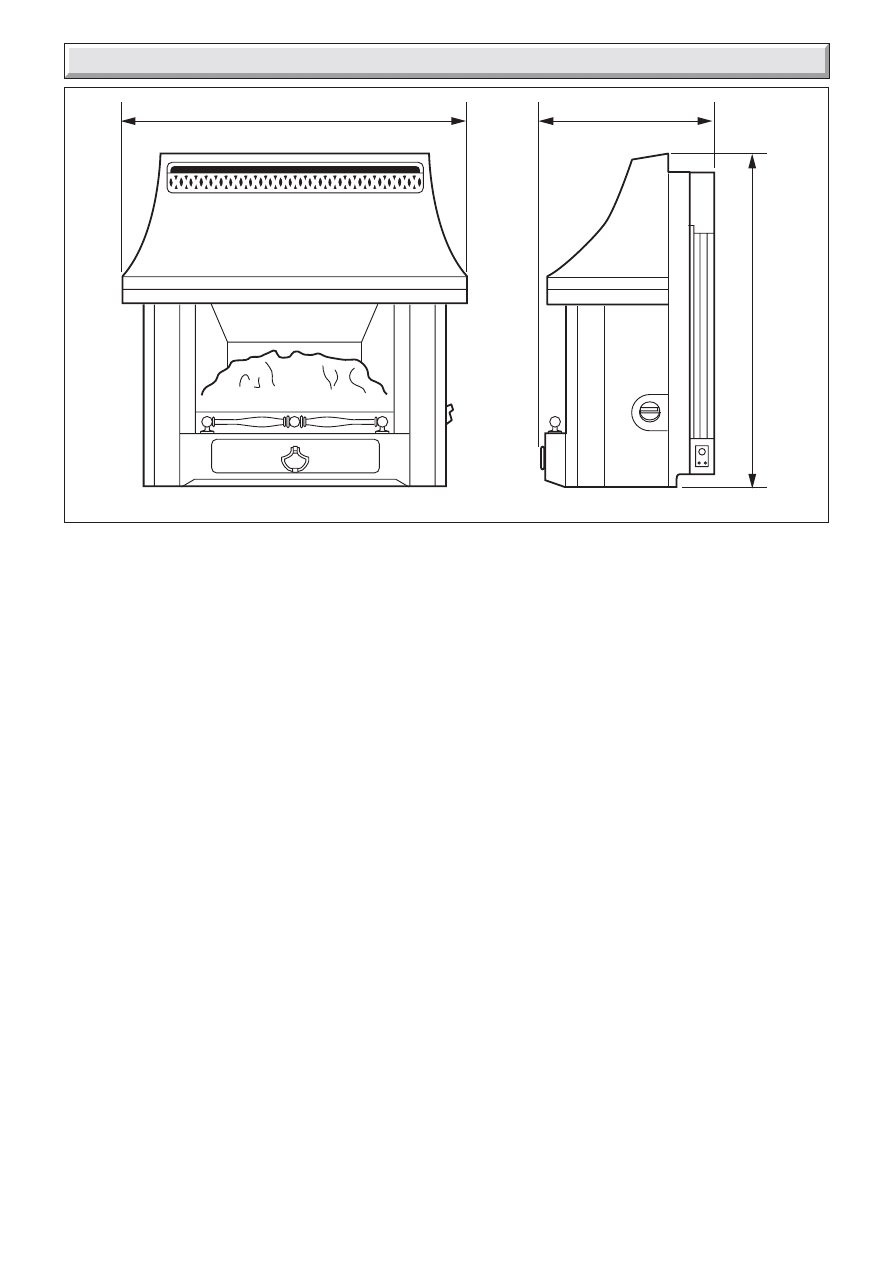
Diagram 1.1
657mm
655mm
302mm
9506

8
221906B
1 General
1.3 Statutory Requirements
The installation must be in accordance with these instructions.
For the user’s protection, in the United Kingdom it is the law that
all gas appliances are installed by competent persons in
accordance with the current edition of the Gas Safety (Installation
and Use) Regulations. Failure to install the appliance correctly
could lead to prosecution. The Council for the Registration of
Gas Installers (CORGI) requires its members to work to
recognised standards.
In the United Kingdom the installation must also be in accordance
with:
All the relevant parts of local regulations.
All relevant codes of practice.
The relevant parts of the current editions of the following British
Standards:-
BS 715, BS EN 1806 , BS 5440 Part 2
BS 6891, BS 1251, BS 4543 Part 2
BS 5871Part 1, BS 1289 Part 1, BS 5440 Part 1,
BS 6461Part 1
In England and Wales, the current edition of the Building
Regulations issued by the Department of the Environment and
the Welsh Office.
In Scotland, the current edition of the Building Standards
(Scotland) Regulations issued by the Scottish Executive.
In Northern Ireland, the current edition of the Building regulations
(Northern Ireland) issued by the Department of the Environment
for Northern Ireland.
In the republic of Ireland the installation must also conform to
the relevant parts of:
a)
The current edition of IS 813
b)
All relevant national and local rules in force.
1.4 Fire Front Location
This fire front can only be fitted to a specially designed Glow-
worm 45/4 & 54/4 Back Boiler Units, which itself has been
installed in accordance with the Glow-worm Installation and
Servicing Instructions.
The back boiler must have been correctly positioned in the
builder’s opening as the fire front is located by connection to the
back boiler.
The back boiler draught diverter and combustion chamber
extension acts as a support for the fire front.
The fire front flue spigot projects into the back boiler draught
diverter assembly.
The gas supply is taken from the back boiler service cock.
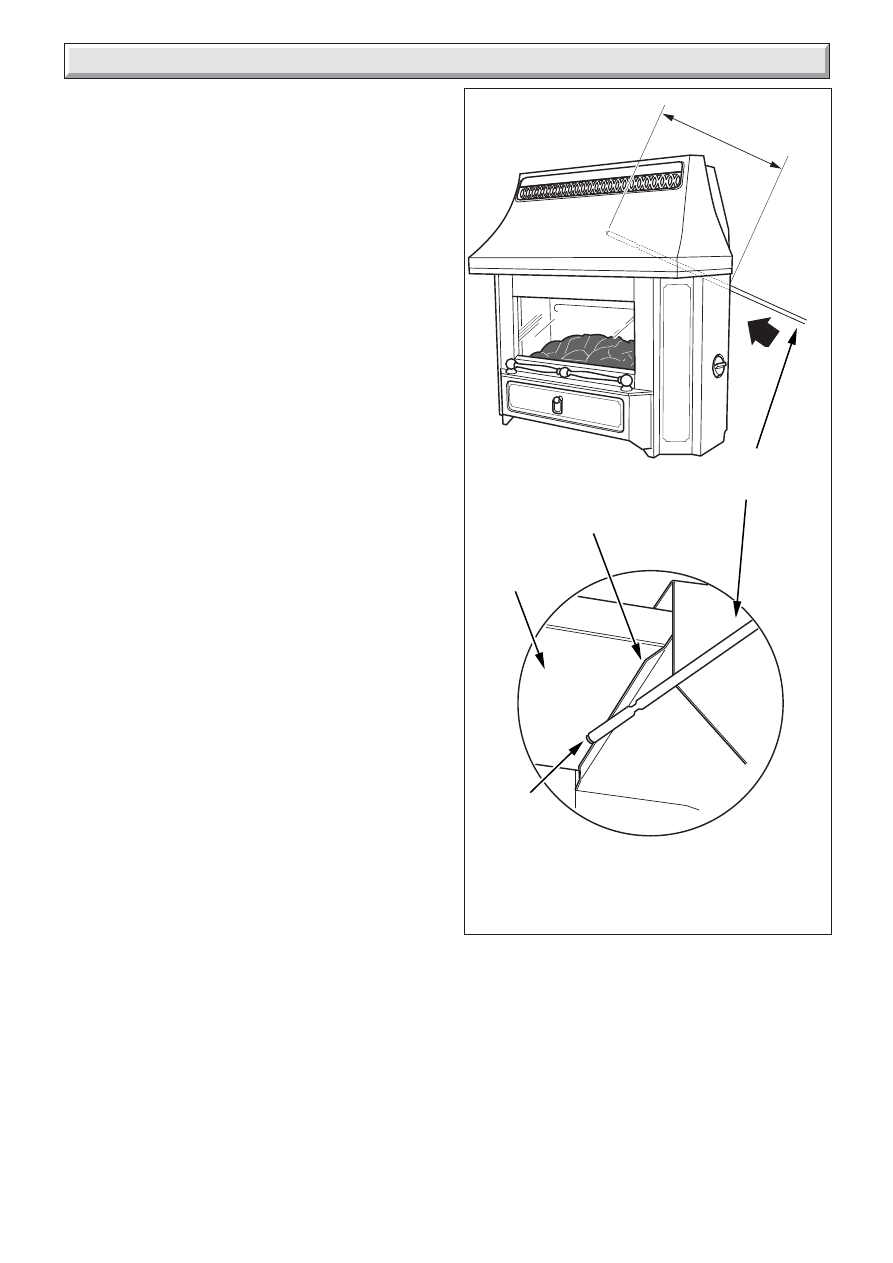
1.5 Clearances
Restrictions should not be placed around the assembled fire
front, see diagram 1 Instructions for Use. A shelf up to 150mm
deep may be fitted above.
Combustible furniture or materials must not be placed closer
than 1 metre in front of the fire front.
2.1 With Hearth
A fireproof hearth under the fire front must have the minimum
dimensions as shown in diagram 2 Instructons for Use.
2.2 With Surround
The fire front casing should cover the opening.
Any combustible material on the fire front fixing face area of the
surround must be removed, see diagram 2.1. This area, to the
depth removed, should then be rendered with a sand/cement
mixture.
2.3 Without Surround or Hearth
The minimum clearances for shelves or projections on the fire
front fixing wall face are as shown in diagram 1, (Instructions for
Use).
The information in the last two paragraphs of “With Surround”
should now be followed.
Under no account must carpet or other combustible material be
laid directly under the fire front, unless the minimum clearances
shown in diagram 2. (Instructions for Use) is achieved.
Diagram 2.1
5506
2 Types of Installation
C
L
640mm
520mm
REMOVE
COMBUSTIBLE
MATERIAL FROM
THIS AREA
BUILDERS
OPENING
INSTALLATION
CENTRE LINE
PREPARED BASE
3.1 Flue
The back boiler flue collector assembly accepts the fire front flue
spigot.
Note. Provision must be made during the installation of the back
boiler for the total ventilation requirement for the combined
appliance. See relevant section in the Back Boiler Installation
Instructions.
3 Types of Flue and Installation
9
221906B
4.1 Unpacking
The carton contains the following:-
1.
Fire assembly.
1.
Ceramic fuel effect (In packaging inside firebox).
1.
Fittings pack.
1.
Gas feed pipe and fittings.
1.
Literature pack.
1.
Tool for window removal.
Remove all the items carefully to prevent damage. Some items
may be contained in the packaging fitments. Examine the
packaging carefully before discarding. Check that all the items
are present and undamaged.
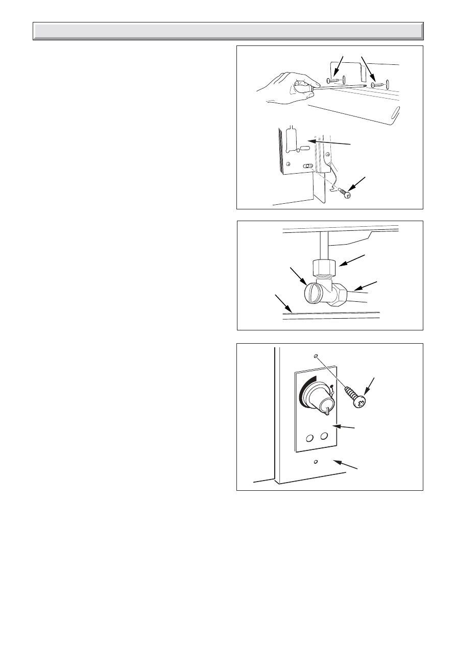
4.2 Appliance Preparation
Stand the fire upright.
Remove the two transit screws from the upper back panel, see
diagram 4.1.
Detach the glass panel surround by sliding it upwards and then
swinging the bottom forwards, see diagram 5 Instructions for
Use.
Remove the control knob by pulling clear of the gas tap spindle.
Remove the control bezel by unscrewing two screws see
diagram 4.2.
Detach the outer case by removing the screws at the case sides
see diagram 4.2.
Pull the bottom of the case forwards while springing the bottom
corners outwards to clear the fixing brackets. Lift the case
upwards and forwards to clear . Place carefully to one side.
IMPORTANT : The front fascia of the case is secured by two
screws as shown in diagram 4.1a. These screws have been
tightened to avoid damage to the case during transit. These
screws must be slackened to enable the customer to
remove this section of the case.
Remove the window unit by turning the screws each side of the
glass panel assembly
1
/
4
turn anticlockwise and lifting clear, see
diagram 7 Instructions for Use.
Remove the fuelbed from the firebox and keep it safe.
4 Fire Front Preparation
Diagram 4.2
CONTROL
BEZEL
RETAINING
SCREW (2)
OUTER CASE
SECURING SCREW (2)
9561
Diagram 4.3
9640
GAS FIRE
FEED PIPE
UNION
NUT
GAS FIRE
SUPPLY
COCK
GAS FIRE
SUPPLY
COCK
CAP
RESTRICTOR
SCREW
WASHER
GAS
SERVICE
COCK
Diagram 4.1
10175
10171
WINDOW SURROUND REMOVAL
Diagram 4.1A
TRANSIT
SCREWS
10
221906B
Diagram 4.6
9494
2.5-4.0mm
GAP
4 Fire Front Preparation
Diagram 4.4
9641
158mm
58mm
FIRE FRONT
WALL DATUM
FIRE FRONT
WALL FACE
GAS FIRE
FEED PIPE
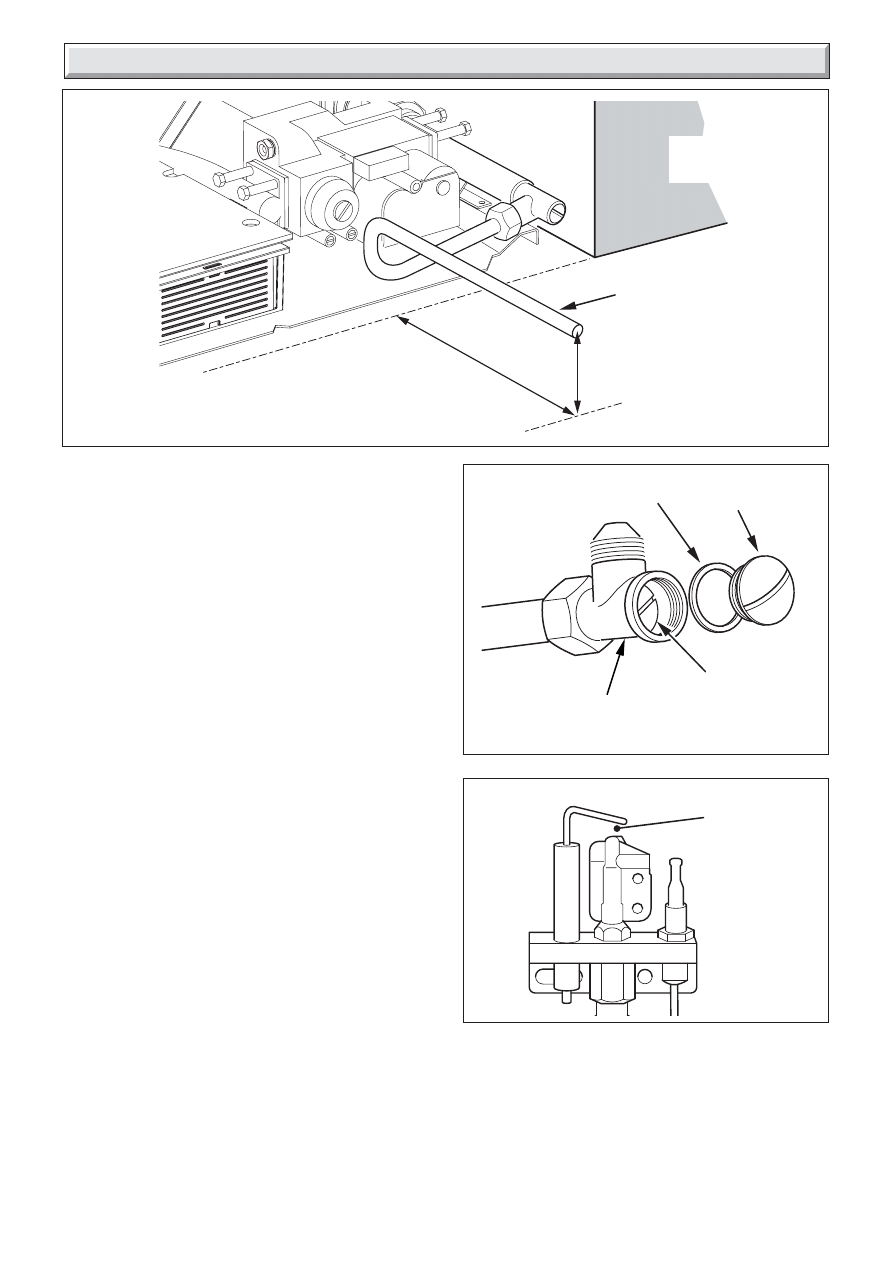
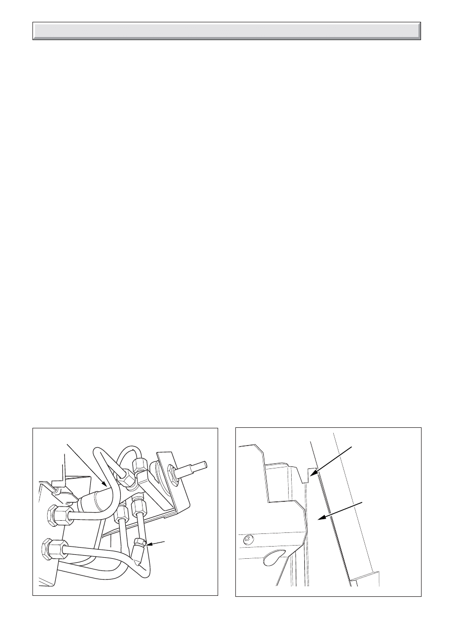
4.3 Gas Supply to Fire Front
Check that the gas service cock is in the Off position.
NOTE: The gas fire feed pipe will need cutting at the plain end
at a point depending upon the position of the BBU to the fire front
wall face.
From the fittings pack, fit the union nut to the flanged end of the
gas fire feed pipe.
Connect the gas fire feed pipe assembly to the gas fire supply
cock, see diagram 4.3.
The gas fire feed pipe must project from the fire front wall face,
158 mm, see diagram 4.4. Measure and cut to suit.
From the fittings pack, fit the gas fire isolating valve to the cut
end of the gas fire feed pipe, ensuring it is positioned correctly,
using an olive and nut, see diagram 4.5.
When fitted check that the gas fire feed pipe, where it projects
from the fire front wall face, is level and the centre of the feed
pipe is 58 mm above the back boiler base plate.
Tighten connections.
Make sure that the gas fire isolating valve is in the Off position
by removing cap and turning restrictor screw clockwise, see
diagram 4.5.
Turn the gas service cock to the On position.
Turn the gas fire supply cock to the On position by removing cap
and turning restrictor screw anti-clockwise, see diagram 4.3.
Pressure check the installation pipework for gas soundness. In
the United Kingdom check in accordance with the current
edition of BS6891. In the Republic of Ireland check in accordance
with the rules in force.
4.4 Check ignition spark
Before attempting to install, it is worth checking that the piezo
electric spark ignition system operates satisfactorily.
To initiate the spark, temporarily refit the control knob to the tap
spindle. Depress the control knob and while keeping it depressed,
turn anticlockwise through approximately 60
o
to the 1/IGN
position. A spark should track from the electrode pin to pilot
burner. If there is no spark or incorrect tracking, check that the
spark gap is between the limits shown in diagram 4.5. If the
spark gap is correct, check the ignition wiring.
Remove the control knob after checking.
Diagram 4.5
9639
FIRE
ISOLATING
VALVE
CAP
WASHER
RESTRICTOR
SCREW
11
221906B
COMBUSTION
CHAMBER
EXTENSION
9472
SECURING
SCREWS (2)
ADJUSTMENT
SCREWS (2)
FIRE FRONT
WALL FACE
FIRE
FRONT
WALL
FACE
43mm
FIRE LOWER
SUPPORT
BRACKETS (2)
9473
FIRE FRONT
WALL FACE
5 Installation
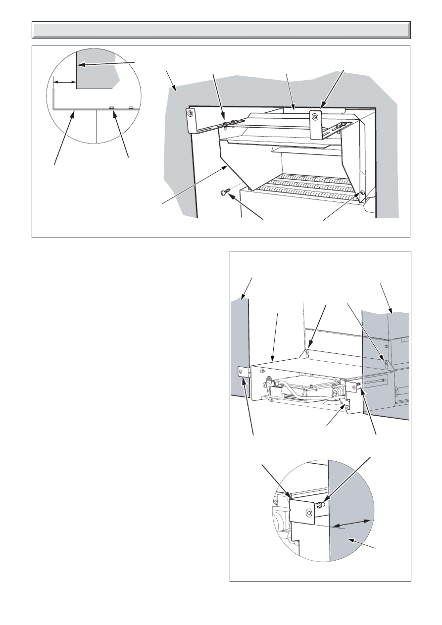
5.1 Fire Front Fixing
Slide the draught diverter, supplied with the boiler, into the
draught diverter body on the BBU and secure with two 5mm dog
point screws, see diagram 5.1.
Fit the two upper fire support brackets on to the draught diverter
with two dog points screws each and adjust so that the end of
each bracket extends about 62 mm from wall face, see diagram
5.1.
Check that the measurement between the centres of the fire
securing holes on the brackets is 238mm and adjust accordingly,
ensuring that the brackets are as near to 90
o
as possible from
the wall face, tighten the dog point screws.
Note. The Boiler User Control is supplied coiled and taped onto
the controls, remove tape an uncoil, carefully place to the right
hand side of the boiler.
Take the combustion chamber extension, supplied with the
back boiler, and fit the lower fire support brackets with two dog
point screws on each but do not tighten.
Fit the combustion chamber extension on the two BBU
combustion chamber front screws and secure, see diagram 5.2.
Note: If the mains electrical supply cable is routed from the right,
secure it with a cable clip, from fittings pack, to the combustion
chamber extension, see diagram 5.2.
Adjust the two lower support brackets so that the end of each
bracket extends about 43 mm from the fire wall front face, see
diagram 5.2.
Lift the fire chassis and position the spigot centrally into the back
boiler unit draught diverter assembly, gently slide the chassis
into place.
Note: It may be necessary to temporally remove the floor
protection plate, see diagram 5.4 to ease installation and fitting
of gas fire feed pipe to fire.
Secure fire chassis to the fire support brackets using the
M5x20mm dog point screws, see diagram 5.3.
Diagram 5.2
Diagram 5.1
9469
FIRE FRONT
WALL FACE
DRAUGHT
DIVERTER
DRAUGHT
DIVERTER BODY
SCREWS (2)
FIRE SUPPORT
BRACKETS (2)
ADJUSTMENT
SCREWS (2)
FIRE
SUPPORT
BRACKET
ADJUSTMENT
SCREWS (2)
62mm
MAINS
CABLE CLIP
POSITION
12
221906B
Diagram 5.4
UNION
NUT
GAS FIRE
FEED PIPE
Diagram 5.5
9480
SECURING
SCREWS (2)
9497
FIRE
ISOLATING
VALVE
BOILER USER
CONTROL
LOUVRE
ASSEMBLY
5 Installation
FLOOR
PROTECTION
PLATE
5.2 Gas Supply Connection
Connect and tighten the union nut at the fire front isolatingvalve,
see diagram 5.4.
Refit floor protection plate if removed.
Turn gas On at the fire isolating valve by removing the cap and
turning restrictor screw anti-clockwise..
Pressure check the installation pipework for gas soundness. In
the United Kingdom check in accordance with the current
edition of BS6891. In the Republic of Ireland check in accordance
with the rules in force.
5.3 Boiler User Control
Remove the two securing screws from the boiler user control.
Place the boiler user control in position from the inside to the
aperture on the bottom of the R/H louvre of the fire chassis,
making sure that it is the correct way up, see diagram 5.5.
Secure from the outside to the louvre with the screws, from
fittings pack, see diagram 5.5.
5.4 Fit the Coal and Glass Panel Assembly
Place the coal bed in position. Make sure that the coal rests on
the ledges at the sides of the firebox and that its back face is
touching the horizontal rib at the back of the firebox, see
diagram 8 Instructions for Use.
Replace the glass panel assembly and secure to the firebox by
turning the two screws 1/4 turn clockwise.
Diagram 5.3
DOG POINT SCREWS
9474
DOG POINT
SCREW (2)
TOP FIXING
BOTTOM FIXING
LOUVRE
ASSEMBLY
13
221906B
GAS
TAP
PRESSURE
TEST
POINT
Diagram 6.1
9498
6.1 Check Control Settings
If closed, open the isolating valve at the inlet elbow.
To help in checking the control positions while the outer case is
detached, place the control bezel over the gas tap spindle and
against the tap bracket. Temporarily secure to the tap bracket
with one of the screws.
Fit the control knob over the gas tap spindle.
Depress the control knob and turn anticlockwise partially towards
the 1/IGN position until some resistance is felt. Keep depressed
at this position to purge air from the system then, while keeping
it depressed, turn fully to the 1/IGN position. A spark should be
generated at the pilot while turning. The spark should ignite the
pilot.
When pilot ignition has been achieved, keep the control knob
depressed for approximately ten seconds to allow the
thermocouple probe to warm up and then release it. If the pilot
does not remain alight, ensure that the air has been purged, that
the pilot orifice is clear and that the thermocouple connections
are sound. Replace the pilot unit if necessary (see servicing
section of this manual).
Check all the control settings. These are:-
Knob
Burner appearance
Position
1/IGN
Centre section on low. Outer sections off.
2
Centre section fully on. Outer sections off.
3
Centre section fully on. Outer sections on low.4
4
Centre and outer sections fully on.
6.2 Flame Supervision Device
The pilot unit incorporates a system which will automatically
shut off the gas supply if the pilot flame goes out or if there is
insufficient oxygen due to spillage or lack of ventilation.
Check that the system operates properly as follows;
Light the appliance. Set at position 4 and leave for one minute.
Turn back to “OFF” to extinguish the pilot. Note the time when
the pilot goes out. Listen for a snap sound at the gas tap. Note
the time when the sound is heard. This sound is caused by an
electromagnetic valve shutting off the gas supply through the
tap. The valve is located in the body of the tap. The valve should
operate within 60 seconds of the pilot going out. If the valve does
not operate within this time limit do not allow the appliance to be
used until the fault has been corrected.
6 Control & Pressure Checks
9496
Diagram 6.2
BACK PANEL
WING (2)
CHASSIS
BACK PANEL
6.3 Flue Blockage Safety Device
This monitoring system must not be adjusted, bypassed or put
out of operation.
This monitoring system, or any of its parts, must only be
exchanged using Glow-worm authorised parts.
6.4 Check Burner Pressure
The appliance is pre-set to give the correct heat input at the inlet
pressure shown in section 1 of this manual. No adjustment is
necessary. Check the burner pressure by fitting a pressure
gauge at the test point, see diagram 6.1. Check the pressure
with the appliance alight and set at maximum output (Control
position 4).
After checking, turn off the appliance. Remove the pressure
gauge and replace the test point sealing screw. Relight the
appliance. Turn to the maximum output position and test around
the sealing screw for gas soundness with a suitable leak
detection fluid.
If all the above checks are satisfactory, continue with the
installation. If not, check the control and ignition circuitry and
components as described in the servicing section of this manual.
6.5 Fit The Outer Case
Refit the outer case. Make sure the ridges on the back of the
outer case is located behind the back panel wings on the
chassis back panel, see diagram 6.2.
Secure the case at the bottom sides with the two screws
previously removed.
Place the control bezel back in position and secure it to the gas
tap bracket with two screws.
Fit the control knob over the gas tap spindle.
Refit the glass panel surround by sliding it upwards to locate its
upper tabs in the slots underneath the outer case hood. Push
the bottom of the surround fully against the case cross panel.
Drop the surround down so that the two screw heads at the back
of the surround locate in the cross panel, see diagram 6
"Instructions for Use".
14
221906B
6.6 Test For Spillage
Note:
1. Take care. The appliance gets hot during testing.
2. To carry out the test you will need a 500mm emplume
tube and a torch.
TEST: WHERE NO FAN IS PRESENT
Close all outside doors and doors and windows in the room in
which the appliance is installed.
Light the fire front only. After 5 minutes apply spillage test.
Position the smoke match tip under the fire front flue duct on the
draught diverter lip by inserting the emplume tube 370mm from
the outside edge of the louvres, see diagram 6.3. During test
smoke should be drawn into the draught diverter and between
the fire front flue duct and the draught diverter lip. If spillage
occurs leave fire front alight for up to a further 10 minutes and
repeat tests.
Next, light the boiler only and after 10 minutes apply spillage test
by positioning smoke match tip as described above, and shown
in diagram 6.3. If spillage occurs, leave the boiler alight for up
to a further 5 minutes and repeat test.
Now light the boiler and fire front. After 10 minutes apply
spillage tests by positioning smoke match tip as described
above, and shown in diagram 6.3. During tests smoke should
be drawn into the boiler draught diverter. If spillage occurs,
leave the boiler and fire front alight for up to a further 5 minutes
and repeat tests.
Note: If spillage does occur smoke will be visible exiting the top
of the fire casing.
TEST. WHERE A FAN IS PRESENT
(A fan means an extractor fan, or a fan for other open flued
appliances, or a circulating fan for a warm air unit, whether or not
gas fired). With the fan switched off carry out the appropriate
spillage test with all doors and windows closed, as above.
If the above tests are satisfactory continue as follows,
Open all doors connecting the room containing the appliance
and the room in which the fan is fitted. Close all other doors and
windows in the premises.
If the fan is in the same room as the appliance close all doors
and windows in that room. Switch on fan and repeat spillage
test as above.
In ALL cases, if spillage continues after the specified test
periods steps MUST be taken to put right the fault(s).
Possible causes include, flue obstructions, down draught or
restricted fresh air supply into the room.
6 Control & Pressure Checks
9519
Diagram 6.3
EMPLUME
TUBE
DRAUGHT
DIVERTER LIP
SMOKE
MATCH
TIP
370mm
VIEW ON ARROW 'A'
(FIRE REMOVED FOR CLARITY)
FIRE FRONT
FLUE DUCT
A

15
221906B
7 Final Review
Please ensure the “Benchmark” logbook (supplied with Back
Boiler Unit) is completed and left with the user.
Check the operation of the fire at all control positions.
Visually inspect the appliance. Clean off any marks incurred
during installation.
Advise the customer how to operate the fire and boiler.
Explain to the customer that the appliance has a flame failure
and spillage monitoring system. Point out the explanation of this
system in the "Instructions for Use".
Advise that if the appliance goes out for any reason, they must
wait at least three minutes before relighting.
Stress that if the monitoring system repeatedly shuts off the
appliance that it must be switched off and their local installation
or service organisation must be contacted or the local gas
undertaking contacted.
Advise the user that the glass may require cleaning periodically
outside and inside as described in the users instructions.
Explain how to remove and replace the glass panel assembly
for cleaning the inside of the glass etc. Point out that a tool is
supplied for releasing the screws. Leave the tool in the instruction
pack.
Advise that the fire may give off a slight odour while new. This
is quite normal and it will disappear after a short period of use.
Advise the customer that they should read the Instructions for
Use before operating the fire and always follow the advice in the
section headed "Cleaning your fire".
If using the appliance for long periods it is beneficial to change
between settings. This will also help to remove any carbon
deposits that may form during use.
Recommend that the appliance should be serviced and the
chimney inspected by a competent person (In the UK a CORGI
registered person) at least annually.
If the appliance is in premises in the United Kingdom occupied
by a tenant, point out that by law a landlord must have any gas
appliance, flue and pipework which is situated in a tenant’s
premises checked for safety at least every 12 months.
Reminder- leave these instructions and the “Benchmark” logbook
with the user.
16
221906B
8 Servicing and Replacement of Parts
Servicing Notes
MAKE SURE THE FIRE FRONT IS COLD.
Servicing must be carried out by a competent person.
After completing a service, always test for gas soundness and
carry out functional check of controls.
Unless stated otherwise all parts are replaced in reverse order
to removal.
Before starting make sure that the gas supply is turned off at the
Fire isolating valve, see diagram 5.4.
NOTE: It is recommended that the back boiler be serviced
before refitting the fire front case, refer to Back Boiler Installation
Instructions.
CAUTION: Disconnect the boiler user control before removing
the fire front chassis when servicing the back boiler unit, refer
to Section 5.
After removing or disconnecting any pipework always make
sure that it is refitted correctly and does not interfere with the
fitting of the fire.
8.1 Servicing
Detach the glass panel surround by sliding it upwards and then
swinging the bottom forwards, see diagram 5 in section,
Instructions for Use. Lift and store carefully.
Remove the control knob by pulling clear of the gas tap spindle.
Remove the control bezel by unscrewing two screws, see
diagram 4.2.
Detach the outer case by removing the screws at the sides, see
diagram 4.2.
Pull the bottom of the case forwards while springing the bottom
corners outwards to clear the fixing brackets. Lift the case
upwards and forwards to clear. Place carefully to one side.
Remove the glass panel assembly by turning the screws each
side of the frame
1
/
4
turn anticlockwise and lifting the unit clear,
see diagram 5 in section, Instructions for Use.
Remove the fuel bed and clean, Refer to "Ceramic Coal" in
Instructions for Use.
Clean all around the fire front chassis with a soft brush or
vacuum cleaner.
Make sure that the electrode spark gap is as shown in diagram
4.6.
Clean injectors as necessary, but, Do not clean injectors with a
wire or sharp instrument.
Clean the burner with a soft brush or vacuum cleaner.
Replace in the reverse order. Make sure that the coal is not
dislodged when refitting.
NOTE: It is recommended that the back boiler unit be seviced
before refitting the fire front case, refer to the Back Boiler
Installation Instructions.
Replacement of Parts Notes
REMEMBER: When replacing a part on this appliance, use only
spare parts that you can be assured conform to the safety and
performance spcification that we require. Do not use
reconditioned or copy parts that have not been clearly authorised
by Hepworth Heating Ltd.
8.2 Fuel Bed
Remove the glass panel assembly as described in section 8.1.
Remove the fuel bed.
When replacing, make sure that the coal rests on the ledges at
the sides of the firebox and that its back face is touching the
horizontal rib at the back of the firebox, see diagram 8 in the
Instructions for Use section.
Replace and secure the glass panel assembly unit to the firebox
by turning the two screws
1
/
4
turn clockwise with the tool
provided. Refit the surround by sliding it upwards to locate its
upper tabs in the slots underneath the outer case hood. Push
the bottom of the surround fully against the case cross panel.
Drop the surround down so that the two screw heads at the back
of the surround locate in the cross panel, see diagram 7 in the
Instructions for Use section.
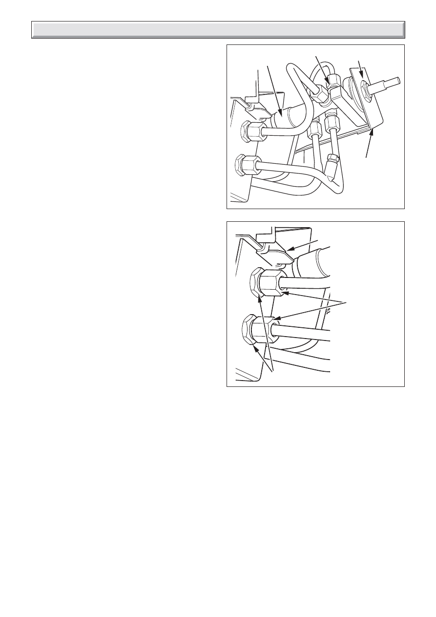
8.3 To Remove The Gas Tap
Remove the outer case as section 8.1.
Detach the electrode lead from the pilot unit by pulling the lead
down and away from the electrode situated at the centre rear of
the burner.
Disconnect the two pipes linking the upper and lower injectors
at the tap end and loosen their connections at the injector ends.
Swing the pipes clear of the tap, see diagram 8.1.
Disconnect the inlet pipe and pilot pipe from the gas tap and
remove the locknut holding the gas tap to the tap bracket, see
diagram 8.1.
Carefully lift the tap clear to allow access to the thermocouple
connection. Disconnect the thermocouple from the tap.
Replace in the reverse order.
Diagram 8.2
9498
Diagram 8.1
9498
PIEZO UNIT
LOCKNUT
GAS TAP
GAS TAP
BRACKET
INJECTOR
COMPRESSION
FITTING
INJECTORS
BURNER MODULE
SUPPORT LIP
17
221906B
8 Servicing and Replacement of Parts
8.4 To Remove The Piezo Generator
Remove the gas tap as section 8.3.
Make sure that the tap is in the off position.
Remove the circlip holding the piezo unit to the tap. Remove the
piezo unit, see diagram 8.1.
Replace in the reverse order.
8.5 To Grease The Control Tap
Detach the tap and remove the piezo generator as section 8.4
making sure that the tap is in the off position.
Remove the two screws from the head of the tap. Remove the
niting head and spindle complete with collar and spring.
Note the position of the slot in the plug - mark its position on the
tap body.
Remove the plug rotating slightly while pulling.
Clean and grease the plug lightly with a suitable grease. Do not
apply excessive grease. Particularly, make sure that the gas
ports in the tap are not restricted by grease.
Push the plug into the tap body and position the slot in line with
the mark previously made on the tap body.
Reassemble the niting head and spindle complete with collar
and spring making sure that the components are correctly
engaged. Check the operation of the tap.
Refit the piezo generator.
8.6 To Remove An Injector
Remove the outer case as section 8.1.
Refer to diagram 8.2.
Release the pipe compression fitting to the upper or lower
injector as required. Lock the injector with a second spanner to
ensure that it does not move.
Loosen the pipe compression fitting at the tap end and move the
pipe clear.
Remove the injector from the burner.
Replace in the reverse order.
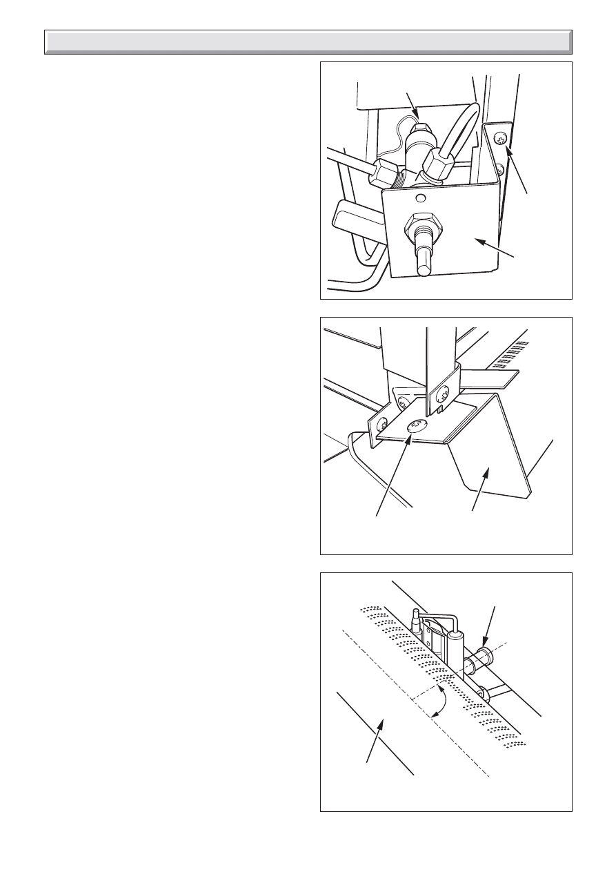
8.7 To Remove The Complete Burner Module,
Pipes and Pilot
Remove the outer case as section 8.1.
Remove the coal as section 8.2.
Support the inlet isolating elbow to avoid straining the pipework
and disconnect the appliance from the elbow.
Detach the gas tap bracket from the right side of the appliance
by removing three screws, see diagram 8.3.
Detach the left side of the burner from the firebox by removing
one screw, see diagram 8.4.
Carefully slide the burner module to free the support lip from the
right side of the firebox, see diagram 8.2.
Remove the pipes, or pilot unit if required.
Replace in the reverse order.
Note:
1.The pilot unit is an atmosphere sensing device. It must be
replaced as a whole assembly. Its individual components are
not separately replaceable.
2.Check that there is no blockage of the air intake tube at the
back of the pilot unit.
To allow optimum air intake, the air intake tube should be be
within the limits of angular relationship to the burner rail shown
in diagram 8.5. Rotate the tube if necessary.
Diagram 8.3
9592
Diagram 8.4
9594
SECURING
SCREW
BURNER
MODULE
GAS TAP
BRACKET
SECURING
SCREW (3)
THERMOCOUPLE
CONNECTION
Diagram 8.5
9599
PILOT AIR
INTAKE TUBE
BURNER
MODULE
70
°
-
110
°
18
221906B
START HERE
Fire will not light
Turn off appliance tap; turn
on appliance tap and
observe spark
Spark
across gap,
ignition
No spark
across
gap
Spark
no
ignition
Using a match, ensure correct
functioning of burner in
all setting positions. Check that
electrode and piezo unit connections
are satisfactory. Check that
burner pressure is as specified.
Correct any fault found.
Spark
across gap,
ignition
No spark
across
gap
Spark
no
ignition
Ensure gap is within specified
tolerance, refer to SERVICING
Turn tap to energise igniter
Disconnect ignition lead from
electrode, place connector
within 4mm of burner and
operate piezo
Spark
across gap,
ignition
Spark
no
ignition
Replace pilot assembly and
reassemble ignition system
Spark
across gap,
ignition
Spark
no
ignition
Ensure gap is within specified
tolerance. Turn tap to energise
igniter
Spark
across gap,
ignition
Spark
no
ignition
Remove ignition lead from piezo unit
and place screwdriver between
appliance chassis earth and piezo
unit, leaving 4mm gap between blade
and spade connector.
Operate igniter.
Spark
across
gap
No spark
across
gap
Renew ignition lead and
reassemble ignition system
Spark
across gap,
ignition
Spark
no
ignition
Change piezo unit and
reassemble ignition system
Spark
across gap
ignition
Check several times that
ignition is satisfactory
END
9 Fault Finding
Diagram 9.1
9631
9.1 Fire Font Ignition
Remove casing as section 8.1.
Refer to Fire Front Ignition Fault Finding, diagram 9.1.
9.2 Flue Blockage Safety Device
If the device operates it indicates there could be a problem with
the chimney. First make sure air vents are free of obstructions,
by carrying out spillage checks as section 6.3.
19
221906B
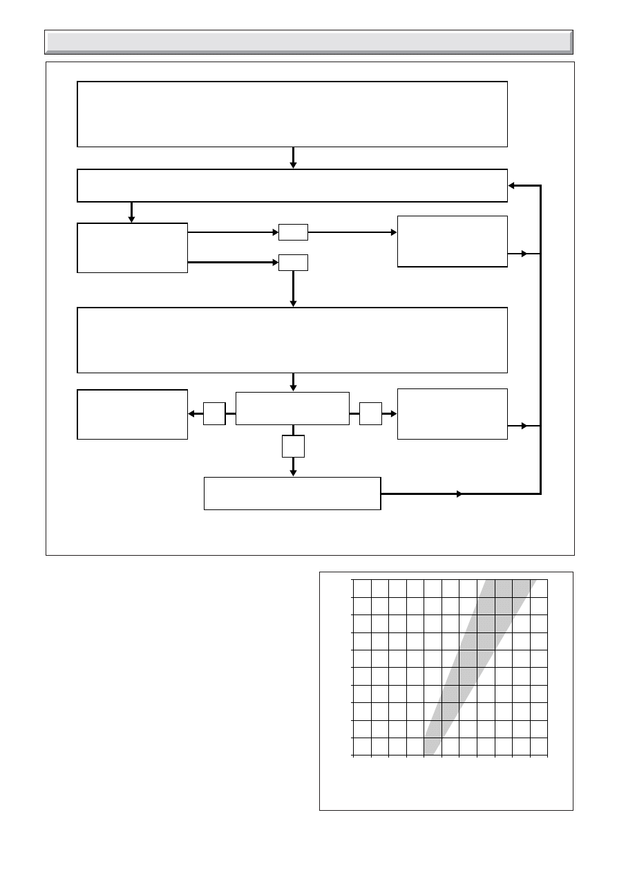
Closed Circuit Voltage (millivolts)
DIAGNOSIS GRAPH FOR FIRE
THERMOCOUPLE CIRCUIT
Open Circuit Voltage (millivolts)
0
1
2
3
4
5
6
7
8
9
10 11
7
8
9
10
11
12
13
14
15
16
17
A
B
C
Diagram 9.2
Diagram 9.3
9.3 Thermocouple
To test a thermocouple, a meter with a range of 0 to 30mV is
required together with a thermocouple interrupter test unit.
Refer to Fault Finding diagram 9.2 and Diagnosis Graph diagram
9.3.
9 Fault Finding
5243
0065M
Disconnect appliance thermocouple from the gas tap. Check that all connections are
clean and in good condition. Fit test meter interrupter into the magnet unit. Fit appliance
thermocouple into the test meter interrupter.
NO
YES
Hold down control tap in ignition position. Ignite burner, allowing thermocouple to attain
operating temperature. Measure the OPEN CIRCUIT voltage.
Is voltage greater
than 15mV?
Faulty thermocouple.
Replace flue blockage
safety device.
Faulty thermocouple.
Replace flue blockage
safety device.
Note the open circuit reading then measure the CLOSED CIRCUIT voltage. Note this voltage.
Referring to the diagnosis graph, mark the open circuit voltage on the VERTICAL axis,
and the closed circuit voltage on the HORIZONTAL axis. Note the point where these
two values intersect on the graph.
THERMOCOUPLE
CIRCUIT IS
SATISFACTORY
In which area of the
graph is the intersect
Faulty magnet unit in gas tap.
Replace gas tap
B
A
C
20
221906B
Because of our constant endeavour for improvement details may vary slightly from those in the instructions.
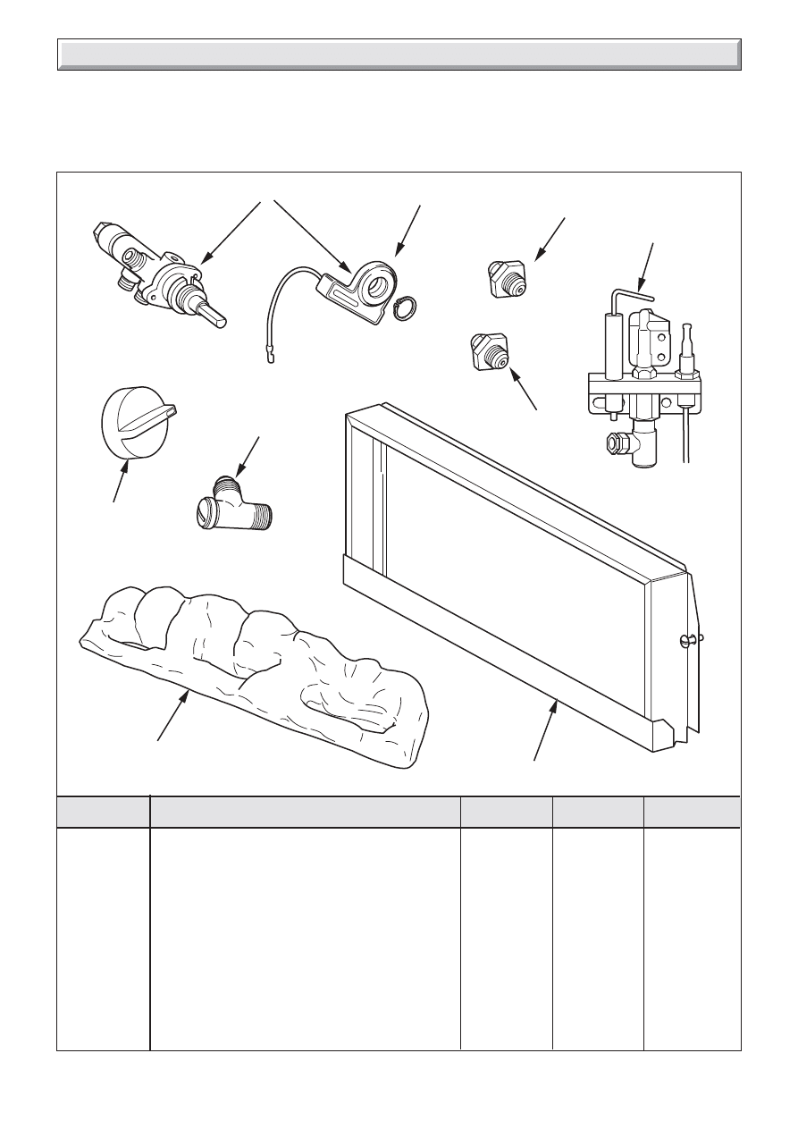
10 Spare Parts
A
Gas Tap & Spark Generator
1
462510
******
B
Spark Generator
1
462511
******
C
Upper injector Bray Cat.99 Size 115
1
462512
******
D
Lower injector Bray Cat.99 Size 230A
1
462513
******
E
Pilot Unit
1
462514
******
F
Control Knob
1
462515
******
G
Inlet & isolating 'T' connector
1
462516
******
H
Glass Panel Assembly
1
462517
******
J
Coal
1
462518
******
Diagram 8.6
KEY
DESCRIPTION
No. OFF
PART No
GC PART No
9598
A
B
C
D
E
F
G
J
H
When spare parts are required apply to your local supplier.
Please quote the name of the appliance, also the serial number which can be found on the data label on the appliance.
If ordering from the local gas undertaking the appropriate appliance GC number should also be quoted together with the GC number
of the part.
Wyszukiwarka
Podobne podstrony:
Glow Worm installation and service manual Black Beauty 4
Glow Worm installation and service manual Hideaway 70CF UIS
Glow Worm installation and service manual Ultimate 50CF UIS
Glow Worm installation and service manual Ultimate 60CF UIS
Glow Worm installation and service manual Glow micron 60
Glow Worm installation and service manual Glow micron 40
Glow Worm installation and service manual Hideaway 80BF UIS
Glow Worm installation and service manual Hideaway 50CF
Glow Worm installation and service manual Energy Saver 60 UI
Glow Worm installation and service manual Hideaway 120BF UIS
Glow Worm installation and service manual Hideaway 120CF UIS
Glow Worm installation and service manual 45 BBU 2
Glow Worm installation and service manual Ultimate 40CF UIS
Glow Worm installation and service manual Glow micron 70
Glow Worm installation and service manual Hideaway 100CF UIS
Glow Worm installation and service manual Miami GF UIS
Glow Worm installation and service manual Hideaway 70BF UIS
więcej podobnych podstron