SPECS 2005
HVAC Academy
The Balancing Act

Air-Conditioning Equipment and Systems
Air-Conditioning Operation
space
space
supply
supply
fan
fan
cooling
cooling
coil
coil
outdoor air
outdoor air
return air
return air
supply air
supply air
exhaust air
exhaust air

Air Conditioning Fans

Air Conditioning Fans
Fan Performance

Measuring Fan Pressure
atmospheric
atmospheric
pressure
pressure
duct
duct
pressure
pressure

Positive Duct Pressure
duct
duct
pressure
pressure
atmospheric
atmospheric
pressure
pressure
3 inches
3 inches
[76.2 mm]
[76.2 mm]

Inclined Manometer
reservoir
reservoir
duct
duct
pressure
pressure
atmospheric
atmospheric
pressure
pressure

Diagnostic Tools For The Service Engineer

What is “Static Pressure”?
velocity
velocity
pressure
pressure
static
static
pressure
pressure
total pressure (P
total pressure (P
t
t
) = static pressure (P
) = static pressure (P
s
s
) + velocity pressure (
) + velocity pressure (
P
P
v
v
)
)
fan
fan

Velocity Pressure vs. Static Pressure
damper
damper
vane
vane
fan
fan

damper
damper
fully open
fully open
Velocity Pressure vs. Static Pressure

damper
damper
partially open
partially open
Velocity Pressure vs. Static Pressure

damper
fully closed
Velocity Pressure vs. Static Pressure

Measuring Static Pressure
inclined
inclined
manometer
manometer

Measuring Total Pressure
inclined
inclined
manometer
manometer

Why does Static Pressure Matter
Add BHP-to-SP relationship equation &
example here

airflow
airflow
static pressure
static pressure
3,438 cfm
3,438 cfm
[1.69 m
[1.69 m
3
3
/s]
/s]
2.0 in. H
2.0 in. H
2
2
O
O
[491 Pa]
[491 Pa]
Fan Performance Points

airflow
airflow
static pressure
static pressure
Plotting Fan Performance Points

blocked
blocked
-
-
tight
tight
static pressure
static pressure
wide
wide
-
-
open
open
airflow
airflow
1,1
00 r
pm
1,1
00 r
pm
airflow
airflow
static pressure
static pressure
Fan Performance Curve

airflow
airflow
static pressure
static pressure
fan s
pee
d
fan s
pee
d
1,1
00 r
pm
1,1
00 r
pm
900
rpm
900
rpm
700 rp
m
700 rp
m
500
rpm
500
rpm
Fan Speed

airflow
airflow
static pressure
static pressure
2 hp
2 hp
3 hp
3 hp
0.5 hp
0.5 hp
1 hp
1 hp
input power
lines
Input Power
More
Energy $
More
Energy $

Tabular Performance Data

In your store:
System Resistance
fan
fan
cooling
cooling
coil
coil
supply duct
supply duct
supply
supply
diffuser
diffuser
return air grille
return air grille
return duct
return duct
damper
damper

static pressure
static pressure
airflow
airflow
3,500 cfm
3,500 cfm
[1.65 m
[1.65 m
3
3
/s]
/s]
2.0 in. H
2.0 in. H
2
2
O
O
[491 Pa]
[491 Pa]
System Resistance

System Resistance Curve
Static Pressure
2
Static Pressure
1
=
=
Airflow
2
Airflow
1
Airflow
2
Airflow
1
2
2

airflow
airflow
static pressure
static pressure
3,500 cfm
3,500 cfm
[1.65 m
[1.65 m
3
3
/s]
/s]
0.65 in. H
0.65 in. H
2
2
O
O
[159 Pa]
[159 Pa]
2,000 cfm
2,000 cfm
[0.94 m
[0.94 m
3
3
/s]
/s]
2.0 in. H
2.0 in. H
2
2
O
O
[491 Pa]
[491 Pa]
system
resistance
curve
system
system
resistance
resistance
curve
curve
System Resistance Curve

airflow
airflow
static pressure
static pressure
design system
resistance curve
design system
design system
resistance curve
resistance curve
A
Fan – System Interaction
surge
region
surge
surge
region
region

airflow
airflow
static pressure
static pressure
surge
region
surge
surge
region
region
B
C
des
ign
fan
sp
eed
des
ign
fan
sp
eed
new
fan
sp
eed
new
fan
sp
eed
A
actual system
resistance curve
actual system
actual system
resistance curve
resistance curve
Higher System Resistance

airflow
airflow
static pressure
static pressure
D
E
new
fan
spe
ed
new
fan
spe
ed
actual system
resistance curve
actual system
actual system
resistance curve
resistance curve
A
surge
region
surge
surge
region
region
de
sign
fan
spe
ed
de
sign
fan
spe
ed
Lower System Resistance

airflow
airflow
static pressure
static pressure
surge
region
surge
surge
region
region
design system
resistance curve
design system
design system
resistance curve
resistance curve
Constant-Volume System

Compressor Diagnosis
Compressor Diagnosis
“THE SYSTEM STANDPOINT”
“THE SYSTEM STANDPOINT”

Air-Conditioning Equipment and Systems
Refrigeration System
compressor
compressor
condenser
condenser
expansion
expansion
device
device
evaporator
evaporator
vapor-
compression
cycle
vapor-
compression
cycle

What Is The
Compressor’s
Job?

Compressor’s Job:
Compressor’s Job:
Increase The Heat Content Of A Gas
Vapor To A Workable Condensing
Temperature

Displace Vapor
From One Area To Another
Compressor’s Job:
Compressor’s Job:

Provide Work Necessary
To Transfer
Electrical Energy Into Heat Energy
Compressor’s Job:
Compressor’s Job:

“
“
Boyle’s Law”
Boyle’s Law”
If You Decrease The Area That A Given
Volume Of Gas Vapor Occupies,
Its Pressure And Density Increase Proportionately

Workable Condensing Temperature?
Workable Condensing Temperature?
This Depends On:
Condensing Surface Area
Condensing Media
Refrigerant Type And Charge
Condensing Pressure And Temperature
Compressor Design
Ambient Temperature
Evaporator Load

Condenser Coil
Condenser Coil
Entering Air
Temperature: 90 F
Leaving Air
Temperature: 120 F
Entering Gas Temp; 200 F
Pressure: 297 psig
Leaving Liquid Temp: 110 F
Ambient Temp:
Ambient Temp:
90 F
90 F
Head Pressure:
Head Pressure:
297 psig
297 psig
Saturated Gas
Saturated Gas
Temp: 130 F
Temp: 130 F

Compression Ratio
The Ratio Of The High Side Absolute Pressure
To The Low Side Absolute Pressure
OR,
How Strong Should I Build My Compressor?

Compression Ratio
Compression Ratio
(Cont’d.)
(Cont’d.)
PRESSURE
ENTHALPY (HEAT) PER POUND OF
REFRIGERANT
EVAPORATING
TEMPERATURE
40F (5 C)
CONDENSING
TEMPERATURE
120F (50 C)
Saturation
Curve
260 psig (18.4 bar)
68.5 psig (4.4 bar)

Compression Ratio Problems
Compression Ratio Problems
Caused By:
Poor System Design
Undersized Condenser
Poor Piping Design
High Head Pressure
Low Suction Pressure
Low Air Flow
Dirty Filters, Coils, Fans
Refrigerant Overcharge
Flooded Condenser

High Compression Ratios
High Compression Ratios
Effects Of:
Excessive Compressor Heat
Excessive Component Wear
End Results
Motor Failure
Compressor Bearing Failure
Inefficiency (Low EER)

Refrigerant Cycle Compressor Dangers
Refrigerant Cycle Compressor Dangers
Refrigerant Slugging
Refrigerant Loss Or Restriction
Oil Dilution
Oil Starvation

Caused By:
Expansion Valve Stuck Open
Incorrect TXV Setting
Short Cycling
Overcharge (Capillary System)
Wrong Size Coil For System Load
Refrigerant Cycle Compressor Dangers
Refrigerant Cycle Compressor Dangers

Refrigerant Slugging
Refrigerant Slugging

Refrigerant Slugging (Cont’d.)
Effect:
Oil Dilution
Oil Foaming
Hydrostatic Compression
Result:
Bearing Wash And Failure
Compressor Valve Failure

Refrigerant Restriction
Caused By:
Broken TXV Sensing Bulb
Loose TXV Sensing Bulb
Wrong TXV Setting
Undersized Piping
System Contamination
Low Evaporator Airflow
Incorrect Orifice Plate

Refrigerant Restriction Causes

Refrigerant Restriction Causes

Refrigerant Restriction Causes

Refrigerant Cycle Compressor Dangers
Effect:
Motor Overheating
Oil Loss
Excessive Superheat
Low Refrigeration Effect
Low Efficiency

Refrigerant Restriction Results

Partial Restriction Points

Electrical Cycle Compressor Dangers
Control Short Cycling
High Voltage (Overvoltage)
Low Voltage (Undervoltage)
Voltage Unbalance
Current Unbalance
Single-Phasing

Control Short Cycling
Improperly Sized Line Transformer
Improperly Sized Wire
Unbalanced Load Per Phase
Loose Wires And Terminals
Corroded Contacts
Low System Voltage:

Voltage And
Current Unbalance

Voltage Unbalance
Can Cause Motor Overheating
Max. Allowable Unbalance =
2%
Definition:
100 Times The Sum of The Deviation of
The Three Voltages, From The Average,
Divided By Twice The Average Voltage

Voltage Unbalance (Cont’d.)
The Three Measured Voltages Are:
221V, 230V and 227V
Average Is:
221 + 230 + 227 = 226V
Voltage Unbalance Is:
100 x [(226-221) + (230-226) + (227-226)] =
2.2%
3
3
2 x 226
2 x 226

What Conditions Create
High Current Flow?

High Current Flow
Caused By:
Excessive Condenser Load
Excessive Evaporator Load
Excessive Refrigerant Load
Undervoltage
Overvoltage
Voltage Unbalance

Compressor Protection Devices
High Pressure Switch
Low Pressure Switch
Current Overloads
Oil Pressure Switch
Motor Temperature Module
Failed Compressor

Diagnostic Tools For The Service Engineer

Predicting Cooling Performance
Superheat
Subcooling
Superheat
Subcooling
?
?

Superheat Is:
The Heat Added To A Refrigerant
Past The Point Of Vaporization
Superheat

Excess Superheat
Causes Motors To Overheat
And Burn Out
Inadequate Superheat
Causes Compressor Slugging
And Valve Breakage
Superheat

Evaporator Coil Refrigerant Level
Proper System
Superheat
12 - 14 F
(6 - 8 C)

Evaporator Coil Refrigerant Level
(Cont’d.)
Low Refrigerant
Flow
High Superheat
20 - 30 F
(11 - 17 C)

Evaporator Coil Refrigerant Level
(Cont’d.)
Excess
Refrigerant
Flow
Low Superheat
0 - 1 F
(0 - 1 C)

What Is Subcooling?
Subcooling

Subcooling
Subcooling
Is:
Is:
The Heat Removed From A
The Heat Removed From A
Refrigerant After It Has
Refrigerant After It Has
Reached Its Condensation
Reached Its Condensation
Point
Point
Subcooling
Subcooling

Excess Subcooling:
Indicates Refrigerant Remaining In
Condenser
Condenser Too Long
Effect On Head Pressure Depends On The
Cause
Subcooling
Subcooling

Subcooling
Subcooling
(Increased Liquid)
(Increased Liquid)
High Head
Pressure
Less Conden-
ser Surface
40 F (22.2 C) SUBCOOLING
20 F (11.1 C)
SUBCOOLING

Subcooling (Cold Weather)
Low ambient
temp-erature
causes liquid
temperature and
head pressure to
drop
50 F (27.8 C) SUBCOOLING
20 F (11.1 C) SUBCOOLING

Subcooling
Causes Flash Gas To Develop In
The Liquid Line Due To Pressure
Drop
Insufficient
Subcooling:

Good Vs. Bad Coil Conditions
Pressure Drop Causes Flash Gas
20 F (11.1 C) SUBCOOLING 0 F (0 C) SUBCOOLING

Good Vs. Bad Coil Conditions
Pressure Drop Causes Flash Gas
20 F (11.1 C) SUBCOOLING 0 F (0 C) SUBCOOLING

The
Balancing
Act
The
Balancing
Act

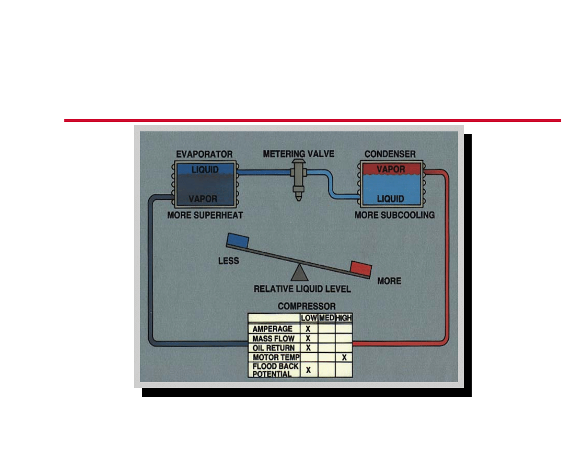
The Balancing Act (Cont’d.)

The Balancing Act (Cont’d.)

The Balancing Act (Cont’d.)

SECTION 4
System
Problems
System
Problems

Important Measurements
Compressor Motor Amp Draw
Liquid Line Pressure
Liquid Line Temperature
Subcooling (Calculation)
Suction Pressure
Suction Line Temperature
Superheat (Calculation)
Evaporator ∆T

Once You Have Your Measurements:
Are They Good?
Are They High?
Are They Low?
Compare To Standard Design
Conditions
Important Measurements (Cont’d.)

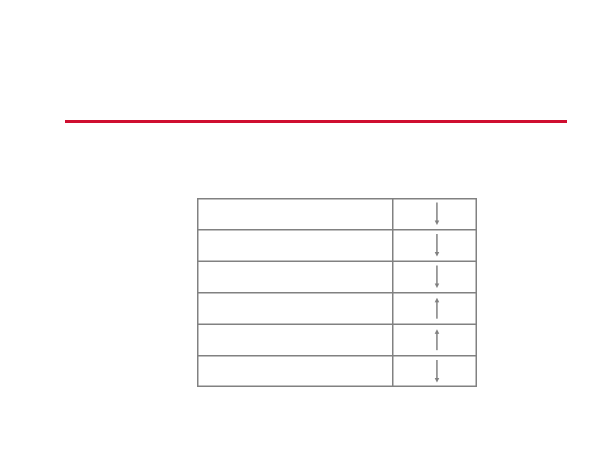
System Problem #1
Symptoms:
AMPERAGE
HEAD PRESSURE
SUBCOOLING
SUCTION PRESSURE
SUPERHEAT
EVAPORATOR ∆ T

System Problem #1
(Cont’d.)

Solution:
Restricted Liquid Line
Restricted Metering Valve (TXV)
Compressor Problems:
Low Motor Cooling
Low Oil Return
Bearing Wear
Motor Insulation Breakdown
System Problem #1
(Cont’d.)

Symptoms:
AMPERAGE
HEAD PRESSURE
SUBCOOLING
SUCTION PRESSURE
SUPERHEAT
EVAPORATOR ∆ T
System Problem #2

System Problem #2
(Cont’d.)

Solution:
Open Metering Valve
(TXV)
Compressor Problems:
Liquid Slugging
Washed Bearings
Oil Foaming
Rod Breakage
System Problem #2
(Cont’d.)

Symptoms:
AMPERAGE
HEAD PRESSURE
SUBCOOLING
SUCTION PRESSURE
SUPERHEAT
EVAPORATOR ∆ T
System Problem #3

System Problem #3
(Cont’d.)

Solution:
Low Condenser Airflow
Compressor Problems:
High Compression Ratio
Bearing Wear
High Motor Amperage
System Problem #3
(Cont’d.)

Symptoms:
AMPERAGE
HEAD PRESSURE
SUBCOOLING
SUCTION PRESSURE
SUPERHEAT
EVAPORATOR ∆ T
System Problem #4

System Problem #4
(Cont’d.)
X
X
X
X
X

Solution:
Low Evaporator Airflow
Compressor Problems:
Motor Failure
Rod Failure
Bearing Failure
System Problem #4
(Cont’d.)

Symptoms:
AMPERAGE
HEAD PRESSURE
SUBCOOLING
SUCTION PRESSURE
SUPERHEAT
EVAPORATOR ∆ T
System Problem #5

System Problem #5
(Cont’d.)

Solution:
Bad Compressor
Compressor Problems:
Motor Overheating
Low Oil Return
Bearing Wear
System Problem #5
(Cont’d.)
Wyszukiwarka
Podobne podstrony:
Open Access and Academic Journal Quality
Academic Word List
hvac override OUT
academicalgebra00milnrich bw
Audel Hvac Fundamentals, Air Conditioning, Heat Pumps And Distribution Systems (Malestrom)
Argentina Soccer Academy Practice[1]
Academic vobulary academic words 4th ed
academicalgebra00milnrich
55 HVAC
Botox, Migraine, and the American Academy of Neurology
Academisch schrijven 13
Instalacja HVAC parter
Bourdieu Homo Academicus
Secret Of The Academy, Slayers fanfiction, Prace niedokończone
Rozpoczecie zajec w Academia Electronica-Instytut Filozofii UJ - GTRK 2014, zarządzanie w kulturze,
Academics’ Opinions on Wikipedia and Open Access Publishing
ACADEMIE, kosmetologia
więcej podobnych podstron