
LabVIEW
TM
Advanced I
Course Manual
Course Software Version 4.0
August 1998 Edition
Part Number 321366C-01
LabVIEW Advanced I Course Manual
Copyright
Copyright © 1996, 1998 by National Instruments Corporation, 6504 Bridge Point Parkway, Austin, Texas 78730-5039.
Under the copyright laws, this publication may not be reproduced or transmitted in any form, electronic or mechanical, including
photocopying, recording, storing in an information retrieval system, or translating, in whole or in part, without the prior written consent
of National Instruments Corporation.
Trademarks
LabVIEW™ and The Software is the Instrument™ are trademarks of National Instruments Corporation.
Product and company names listed are trademarks or trade names of their respective companies.

Internet Support
E-mail:
support@natinst.com
FTP Site:
ftp.natinst.com
Web Address:
http://www.natinst.com
Bulletin Board Support
BBS United States: 512 794 5422
BBS United Kingdom: 01635 551422
BBS France: 01 48 65 15 59
Fax-on-Demand Support
512 418 1111
Telephone Support (USA)
Tel: 512 683 8248
Fax: 512 683 5678
International Offices
Australia 03 9879 5166, Austria 0662 45 79 90 0, Belgium 02 757 00 20, Brazil 011 288 3336, Canada (Ontario) 905 785 0085,
Canada (Québec) 514 694 8521, Denmark 45 76 26 00, Finland 09 725 725 11, France 01 48 14 24 24, Germany 089 741 31 30,
Hong Kong 2645 3186, Israel 03 6120092, Italy 02 413091, Japan 03 5472 2970, Korea 02 596 7456, Mexico 5 520 2635,
Netherlands 0348 433466, Norway 32 84 84 00, Singapore 2265886, Spain 91 640 0085, Sweden 08 730 49 70,
Switzerland 056 200 51 51, Taiwan 02 377 1200, United Kingdom 01635 523545
National Instruments Corporate Headquarters
6504 Bridge Point Parkway
Austin, Texas 78730-5039
USA Tel: 512 683 0100

Contents
©
National Instruments Corporation
iii
LabVIEW Advanced I Course Manual
Course Slides and Text
Module 1—Memory Management and Multithreading
Introduction................................................................................................................. 1
Lesson 1—LabVIEW Memory Basics ....................................................................... 8
Lesson 2—VI Components in Memory...................................................................... 22
Lesson 3—Data Types and Structures in Memory..................................................... 43
Lesson 4—Multithreading Issues ............................................................................... 89
Module 2—Connectivity
Introduction................................................................................................................. 113
Lesson 1—TCP/IP ...................................................................................................... 120
Lesson 2—VI Server .................................................................................................. 141
Lesson 3—ActiveX Automation Server ..................................................................... 182
Lesson 4—ActiveX Automation Client and ActiveX Container ............................... 202
Module 3—Calling External Functions
Introduction................................................................................................................. 227
Lesson 1—CIN Basics................................................................................................ 234
Lesson 2—LabVIEW Managers................................................................................. 257
Lesson 3—Passing Parameters ................................................................................... 273
Lesson 4—Advanced CIN Topics .............................................................................. 294
Lesson 5—Calling DLLs ............................................................................................ 315
Lesson 4—Writing DLLs ........................................................................................... 330
Module 1 Exercises
Lesson 1
Exercise 1-1 ................................................................................................................ 1-1-1
Additional Exercises ................................................................................................... 1-1-4

Contents
LabVIEW Advanced I Course Manual
iv
©
National Instruments Corporation
Lesson 2
Exercise 2-1 ................................................................................................................1-2-1
Exercise 2-2 ................................................................................................................1-2-5
Exercise 2-3 ................................................................................................................1-2-6
Additional Exercise.....................................................................................................1-2-8
Lesson 3
Exercise 3-1 ................................................................................................................1-3-1
Exercise 3-2 ................................................................................................................1-3-3
Exercise 3-3 ................................................................................................................1-3-6
Exercise 3-4 ................................................................................................................1-3-9
Exercise 3-5 ................................................................................................................1-3-12
Exercise 3-6 ................................................................................................................1-3-14
Exercise 3-7 ................................................................................................................1-3-17
Additional Exercises ...................................................................................................1-3-21
Lesson 4
Exercise 4-1 ................................................................................................................1-4-1
Exercise 4-2 ................................................................................................................1-4-4
Exercise 4-3 ................................................................................................................1-4-6
Exercise 4-4 ................................................................................................................1-4-9
Module 2 Exercises
Lesson 1
Exercise 1-1 ................................................................................................................2-1-1
Exercise 1-2 ................................................................................................................2-1-3
Exercise 1-3 ................................................................................................................2-1-7
Exercise 1-4 ................................................................................................................2-1-13
Additional Exercises ...................................................................................................2-1-17
Lesson 2
Exercise 2-1 ................................................................................................................2-2-1
Exercise 2-2 ................................................................................................................2-2-3
Exercise 2-3 ................................................................................................................2-2-7
Exercise 2-4 ................................................................................................................2-2-10
Lesson 3
Exercise 3-1 ................................................................................................................2-3-1
Exercise 3-2 ................................................................................................................2-3-5
Exercise 3-3 ................................................................................................................2-3-8
Lesson 4
Exercise 4-1 ................................................................................................................2-4-1

Contents
©
National Instruments Corporation
v
LabVIEW Advanced I Course Manual
Exercise 4-2 ................................................................................................................2-4-3
Exercise 4-3 ................................................................................................................2-4-5
Exercise 4-4 ................................................................................................................2-4-7
Exercise 4-5 ................................................................................................................2-4-9
Module 3 Exercises
Lesson 1
Exercise 1-1 ................................................................................................................3-1-1
Lesson 2
Exercise 2-1 ................................................................................................................3-2-1
Exercise 2-2 ................................................................................................................3-2-3
Exercise 2-3 ................................................................................................................3-2-4
Lesson 3
Exercise 3-1 ................................................................................................................3-3-1
Exercise 3-2 ................................................................................................................3-3-5
Exercise 3-3 ................................................................................................................3-3-7
Exercise 3-4 ................................................................................................................3-3-9
Exercise 3-5 ................................................................................................................3-3-11
Exercise 3-6 ................................................................................................................3-3-14
Exercise 3-7 ................................................................................................................3-3-16
Additional Exercises ...................................................................................................3-3-18
Lesson 4
Exercise 4-1 ................................................................................................................3-4-1
Exercise 4-2 ................................................................................................................3-4-4
Exercise 4-3 ................................................................................................................3-4-6
Exercise 4-4 ................................................................................................................3-4-10
Lesson 5
Exercise 5-1 ................................................................................................................3-5-1
Exercise 5-2 ................................................................................................................3-5-8
Additional Exercise.....................................................................................................3-5-13
Lesson 6
Exercise 6-1 ................................................................................................................3-6-1
Exercise 6-2A .............................................................................................................3-6-7
Exercise 6-2B..............................................................................................................3-6-12
Exercise 6-3A .............................................................................................................3-6-16
Exercise 6-3B..............................................................................................................3-6-20
Exercise 6-4 ................................................................................................................3-6-25

Contents
LabVIEW Advanced I Course Manual
vi
©
National Instruments Corporation
Appendix
A. Application Notes .................................................................................................A-2
B. The LabVIEW Style Guide...................................................................................A-3
C. Remote Automation using DCOM .......................................................................A-4
D. Dynamic Data Exchange ......................................................................................A-15
Exercise A-1 ...............................................................................................................A-19
Exercise A-2 ...............................................................................................................A-24
E. Networked DDE (NetDDE)..................................................................................A-30
Exercise A-3 ...............................................................................................................A-33
F. The LabVIEW Internet Toolkit ............................................................................A-36
G. Common Questions about Writing and Calling DLLs .........................................A-39
H. Common Questions about CINs ...........................................................................A-41
I.
Instructor’s Notes..................................................................................................A-43

LabVIEW Advanced 1 Course Manual
1
© National Instruments Corporation
Introduction
In conventional programming, memory allocation is the cause of many
problems and poor performance. Because LabVIEW is a programming
language, many of the same issues can affect your LabVIEW VIs. Memory
management using LabVIEW can be especially difficult because LabVIEW
handles the allocation and deallocation of memory transparently.
This module teaches you how to monitor and optimize LabVIEW memory use.
This module refers to good LabVIEW programming style and discusses several
general memory rules. It discusses the different data types in LabVIEW in
detail, concentrating on arrays and strings, with regard to memory use. This
module also teaches you about the multithreading capabilities of LabVIEW.
Hands-on exercises reinforce the various concepts.
Course Description
The LabVIEW Memory Management and Multithreading module teaches you
to make optimum use of LabVIEW for developing your applications. The
course is divided into lessons, each covering a topic or a set of topics. Each
lesson consists of:
•
An introduction that describes the lesson’s purpose and what you will learn.
•
A discussion of the topics
•
A set of exercises to reinforce the topics presented in the discussion.
•
A set of additional exercises to be done if time permits.
•
A summary that outlines important concepts and skills taught in the lesson.
LV Adv I 1
LabVIEW Advanced I Course
Module 1
Memory Management
and Multithreading
National Instruments
11500 N. MoPac Expressway
Austin, Texas 78759
(512) 683-0100
TM

LabVIEW Advanced 1 Course Manual
2
© National Instruments Corporation
Listed above are the various ways you can contact National Instruments for technical support.
LV Adv I 2
National Instruments Technical Support Options
Telephone Support (USA):
Fax
.............................................................
(512) 683-5678
Telephone
...........................................
(512)
683-8248
Fax-on-Demand: 24-hour information retrieval system with
a library of documents
.............…
(512) 683-1111
Internet Support:
Web Support - searchable KnowledgeBase, support
documents, and files
................
http://www.natinst.com
.......................................................
support@natinst.com
FTP - contains support files and documents to download
FTP Site:
ftp.natinst.com
login:
anonymous
password:
your Internet address

LabVIEW Advanced 1 Course Manual
3
© National Instruments Corporation
This course prepares you for the items listed above.
Additional optional exercises at the end of the lessons challenge you to enhance the basic
application features. Specific details regarding the program capabilities are in the relevant
exercises.
LV Adv I 3
Course Goals
• Understand system memory issues
• Monitor memory use
• Understand how the components of a VI use memory
• Understand the importance of using subVIs in LabVIEW
applications
• Understand memory use of arrays, strings, and other
data types
• Understand how local and global variables use memory
• Optimize the memory use in your applications with the
above information
• Understand how multithreading works in LabVIEW
• Understand how to optimize multithreaded tasks in
your VIs

LabVIEW Advanced 1 Course Manual
4
© National Instruments Corporation
It is not the purpose of this course to discuss any of the items listed above.
LV Adv I 4
Course Non-Goals
•
To teach LabVIEW basics
•
To teach programming theory
•
To discuss every built-in LabVIEW object, function,
or library VI
•
The development of a complete application for any
student in the class

LabVIEW Advanced 1 Course Manual
5
© National Instruments Corporation
The LabVIEW Memory Management Module is a one-day course. Here is a rough timeframe
for the material covered:
Lesson 1:
LabVIEW Memory Basics
Break
Lesson 2:
VI Components in Memory
Lunch
Lesson 3:
Data Types and Structures in Memory
Break
Lesson 4:
Multithreading in LabVIEW
LV Adv I 5
Course Outline
LabVIEW Memory Basics
VI Components in Memory
Data Types and Structures
in Memory
Multithreading Issues

LabVIEW Advanced 1 Course Manual
6
© National Instruments Corporation
Items You Will Need for this Course Module:
•
Computer running Windows 95/NT/98
•
LabVIEW for Windows Full Development System, ver. 5.0 or later
•
LabVIEW Advanced I Course Manual and disks
•
MIO Series DAQ board
•
DAQ Signal Accessory and cable
•
Optional—A word processing application such as Notepad or Wordpad
Install the course software by inserting the first course disk and double-clicking on the file
Module1.exe
. Extract the contents of this self-extracting archive into your
C:\
directory.
All of the files you need will be installed into the
C:\Exercises\LV_AdvI
directory. The
solutions to all the exercises will be installed into the
C:\Solutions\LV_AdvI
directory.
LV Adv I 6
Equipment Needed for this Course
Computer running Windows 95/NT/98
LabVIEW for Windows
ver. 5.0 or later
LabVIEW Advanced I
Course Manual
LabVIEW Advanced I
course disks
DAQ MIO Board
MIO Series
DAQ Board
DAQ Signal
Accessory

LabVIEW Advanced 1 Course Manual
7
© National Instruments Corporation
LV Adv I 7
Hands-On Exercises
• Exercises reinforce
the topics presented
• Each exercise shows
a finished VI after it
was run
• Descriptions of how
to build the VI follow
the picture
• Save exercises into
the VI library shown
here:
Logdata.txt

LabVIEW Advanced 1 Course Manual
8
© National Instruments Corporation
Introduction
This lesson gives an introduction to computer memory use with LabVIEW.
Because LabVIEW handles memory management for you, it is important to
know how and when memory is allocated. LabVIEW contains many tools,
utilities, and examples to help you monitor computer memory use.
LV Adv I 8
You Will Learn:
A. Some basic issues about LabVIEW and
memory use
B. Some system memory issues with LabVIEW
C. About the memory components of a VI
D. Ways to monitor memory use in LabVIEW
Lesson 1
LabVIEW Memory Basics

LabVIEW Advanced 1 Course Manual
9
© National Instruments Corporation
A. Introduction to LabVIEW and Memory
In conventional C, C++, or Pascal programming, memory allocation,
reallocation, and deallocation are the cause of many bugs and performance
bottlenecks. In C, for example, you explicitly allocate memory (with the
malloc()
function), and must remember to deallocate it when you are through
using it. No bounds checking exists when you write to this memory, so you must
add your own tests to make sure you do not corrupt memory. (That is why
people make money selling
malloc
-debugging libraries.)
LabVIEW takes care of most of these memory details. The memory allocation
still happens; it is just not explicit on the LabVIEW diagram. So why talk about
memory issues at all if LabVIEW already does it for you?
Because LabVIEW handles the memory allocation and deallocation behind the
scenes, you do not have as much control over memory management. If you have
a LabVIEW application or VI that runs out of memory, you may not know where
to start fixing the problems. The purpose of this course is to teach you how
LabVIEW handles memory and show you what aspects you can control and
ways to optimize the aspects you cannot control. Also, an understanding of how
to minimize memory usage can help to increase VI execution speeds, because
memory allocation and copying data can take a considerable amount of time.
LV Adv I 9
Why Talk About LabVIEW
Memory Management?
• LabVIEW handles memory allocation for you
– No allocating or freeing memory
– No array bounds-checking
• Because memory allocation is automatic, you
have less control over when it happens
• The most common and most mysterious reason
for poor performance of VIs in LabVIEW relates
to memory usage

LabVIEW Advanced 1 Course Manual
10
© National Instruments Corporation
Good Programming Style
The best way to improve LabVIEW memory usage is to use good
programming style. This course will be specifically focused on memory
use and will show some good programming techniques. Several other
references where you can get more information about good programming
style with LabVIEW are listed on the slide above. You can find more
information about obtaining any of these references from the NI Web page
at
http://www.natinst.com
.
•
The G Programming Reference Manual, Chapter 28—Performance
Issues discusses program execution speed and memory use.
•
The LabVIEW User Manual, Chapter 28—Program Design discusses
good programming style and methods of writing VIs.
•
The LabVIEW with Style book by Gary W. Johnson and Meg Kay
includes tips and techniques for building LabVIEW applications. You
can obtain this document from National Instruments via any of the
support options listed near the beginning of this course manual.
•
The LabVIEW Application Notes and Technical Notes contain
information regarding memory management, multithreading, and good
programming style. You can obtain these from National Instruments
using any of the support options listed in the beginning of this course
manual.
LV Adv I 10
The Best Way to Improve Memory Usage
Is to Use Good Programming Style
• The
G Programming Reference Manual, Chapter 28 -
Performance Issues
• The
LabVIEW User Manual, Chapter 28 - Program Design
• The
LabVIEW with Style document by Gary W. Johnson and
Meg Kay
• LabVIEW Application and Technical Notes
• LabVIEW Technical Resource (LTR) Newsletter
•
LabVIEW Graphical Programming by Gary W. Johnson
•
LabVIEW for Everyone by Lisa K. Wells and Jeffrey Travis
• Presentations by LabVIEW Software Engineers at LabVIEW
User Group Meetings, NI User Symposia, and NI Developers’
Conferences

LabVIEW Advanced 1 Course Manual
11
© National Instruments Corporation
•
The LabVIEW Technical Resource (LTR) is a quarterly newsletter circulated
by LabVIEW consultants and includes articles on all aspects of LabVIEW
programming. A diskette is included with each issue and contains all of the
VIs discussed in that newsletter. (For more information, contact LTR
Publishing at (214) 706-0587, fax (214) 706-0506, e-mail:
ltr@ltrpub.com
,
web: www.ltrpub.com.)
•
LabVIEW Graphical Programming by Gary W. Johnson is a book about
programming with LabVIEW. It includes many application descriptions and
discussions on programming techniques. McGraw-Hill publishes this book
and its ISBN is 0-07-032915-X.
•
LabVIEW for Everyone by Lisa K. Wells and Jeffrey Travis is a beginner’s
guide to LabVIEW programming. It is published by Prentice Hall and has
the ISBN 0-13-268194-3.
•
The LabVIEW software and applications engineers give presentations at
LabVIEW user group meetings, The National Instruments User Symposia,
and the National Instruments Developer Conferences.

LabVIEW Advanced 1 Course Manual
12
© National Instruments Corporation
B. LabVIEW Memory
This section discusses how LabVIEW allocates memory when it launches and the
LabVIEW components that use memory.
Windows/Sun/HP-UX
LabVIEW allocates a single block of memory when it is launched. When you
load a VI, its components are loaded into this block of memory. Likewise, when
you run a VI, all the memory that it manipulates is allocated from this block.
When LabVIEW is low on memory, more memory is dynamically allocated
through the operating system. This process is transparent to the user.
Macintosh/Power Macintosh
LabVIEW allocates a single block of memory at launch time, out of which all
subsequent allocations are performed. You configure the amount of memory that
LabVIEW allocates at launch time in the Get Info option from the File menu in
the Finder. Note that if LabVIEW runs out of memory, it cannot increase the
size of this memory pool. Therefore, you should set this parameter as large as
possible.
LV Adv I 12
LabVIEW Memory
• Windows/Sun/HP-UX
– Memory allocated dynamically as needed
• Macintosh
– Assign memory size using Get Info…
– Memory block allocated at launch time
– Fragmentation; be aware of other
applications running

LabVIEW Advanced 1 Course Manual
13
© National Instruments Corporation
Virtual Memory
If you have a machine with a limited amount of memory, you may want to
consider using virtual memory to increase the amount of memory available for
applications. Virtual memory is a capability of your operating system by which
it uses available disk space for RAM storage. If you allocate a large amount of
virtual memory, applications perceive this as memory that is generally available
for storage.
Windows 95/NT/98, Sun, and HP-UX automatically manage virtual memory
allocation. In Windows 3.x, you allocate virtual memory in the 386 Enhanced
program located in the Control Panel of the Main program group. On the
Macintosh, you allocate virtual memory using the Memory device in the Control
Panel folder.
LabVIEW does not differentiate between RAM and virtual memory. The
operating system hides the fact that the memory is virtual. However, accessing
data stored in virtual memory is much slower than accessing data stored in
physical RAM. With virtual memory, you may occasionally notice more
sluggish performance, when memory is swapped to and from the hard disk by the
operating system. Virtual memory can help run larger applications, but it is
probably not appropriate for applications that have critical time constraints.
LV Adv I 13
System Memory Issues
• Virtual memory
– Uses hard drive as RAM
– Can help to run larger applications
– Managed automatically in
Windows 95/NT/98, Sun, and HP-UX
– User must configure for Windows 3.x,
Macintosh, and Power Macintosh
– Not recommended for applications with
critical time constraints

LabVIEW Advanced 1 Course Manual
14
© National Instruments Corporation
C. VI Components
VIs have four main conceptual components: the front panel, the block diagram,
the icon, and the connector pane. However, these are not the VI components we
will discuss in respect to memory use in LabVIEW.
The four VI structure components listed above (front panel, block diagram,
compiled code, and data space) are the four major components in memory. You
never actually see the code, and you see the data only when it is represented on
the front panel. There are many other minor components to a VI, such as the
icons, descriptions, and so on, but these are small compared to the “big four”
listed above.
LV Adv I 14
VI Data Structures in Memory
Front Panel
Block Diagram
Code
• Diagram compiled
into machine code
Front
Panel
Block
Diagram
Code
Data
Space
Data Space
• Control/indicator values
• Default data
• Block diagram constant
data
• Dynamically defined data

LabVIEW Advanced 1 Course Manual
15
© National Instruments Corporation
When you open a VI, LabVIEW loads the front panel, the code (if it matches the
platform), and the data for the VI into memory. If the VI needs to be recompiled because
of a change in platform or in the interface to a subVI, LabVIEW loads the diagram into
memory as well.
Therefore, LabVIEW loads only the structure components it needs into memory, and
other parts are loaded later as needed. For example, a typical subVI has just its code and
data loaded when its parent VI is loaded. If you go to the parent’s diagram and double-
click on the subVI, the subVI panel will be loaded into memory. If you then select
“Show Diagram,” the subVI diagram will load into memory.
As shown above, you can save memory by converting some of your VI components into
subVIs. If you create a single, large VI with no subVIs, you end up with the front panel,
code, and data for that top-level VI in memory. If the VI is broken into subVIs, the code
for the top-level VI is smaller, and only the code and data of the subVIs are in memory.
In some cases, you may actually see lower run-time memory usage because the data
space in subVIs can be reused if the subVI is not running. You may also find that
massive VIs take longer to edit. You do not see this problem as much if you break your
VI into subVIs, because the LabVIEW editor can handle smaller VIs more efficiently.
This is in addition to the fact that a more hierarchical organization to your VIs is
generally easier to maintain and read.
LabVIEW has a variety of reasons for needing to load various parts of a VI. These are
discussed in the next lesson.
LV Adv I 15
When a VI Is Loaded into Memory
• Data is always loaded
• Code is loaded if platforms match
(68K, PPC, Win 95/NT/98, SPARC, HP-UX)
• Panel and Diagram are loaded if needed
(recompiling)
Front
Panel
Block
Diagram
Code
Data
Space
Front
Panel
Block
Diagram
Code
Data
Space
Main VI
SubVI
Always in memory
Resident sometimes

LabVIEW Advanced 1 Course Manual
16
© National Instruments Corporation
D. Ways to Monitor Memory Use
Before you can begin to use memory more efficiently or understand how
LabVIEW uses memory, you need to be able to monitor LabVIEW
memory usage. LabVIEW includes several tools and utilities you can use
to figure out how much memory is being used. We will discuss each of
them here and you will be using these different methods throughout the
course to examine how memory gets allocated and deallocated.
About LabVIEW…
To determine how much total memory LabVIEW has allocated from the
operating system, you can select the About LabVIEW... option from the
Help menu. The memory value that appears includes memory for VIs as
well as memory that LabVIEW uses. You can check this amount before
and after execution of a set of VIs to get an idea of how much memory is
being used. The About LabVIEW box is shown in the slide above and
indicates that LabVIEW has allocated about 3.5 MB of memory from the
operating system.
LV Adv I 16
Monitoring Memory Usage
About LabVIEW... (Help Menu)

LabVIEW Advanced 1 Course Manual
17
© National Instruments Corporation
Show VI Info…
You can use the Show VI Info... option from the Windows menu as shown
above to get a breakdown of the memory usage for a specific VI. The left
column summarizes memory used for resources, and the right column
summarizes how much RAM is being used for the various structure components
of the VI. Note that the information does not include memory usage of subVIs.
LV Adv I 17
Monitoring Memory Usage
Show VI Info...
(Windows Menu)

LabVIEW Advanced 1 Course Manual
18
© National Instruments Corporation
Profile Window
LabVIEW 4.0 introduced a new utility for monitoring memory use. The Profile
window displays the performance information for all VIs in memory in an
interactive tabular format. From that window, you can choose the type of
information to gather and sort the information by category. You can also monitor
subVI performance within different VIs. To show the Profile window, select
Show Profile Window from the Project menu. The window will appear as
shown above.
You can view the profiling statistics for the memory use of each VI in memory as
well as the timing information for VI execution. This course will concentrate
upon the memory statistics. To collect memory statistics with the Profile window,
you must select the Profile Memory Usage option before starting the profiling
session. You can also select the Memory Usage option after starting the Profiler
to collect additional memory information.
Note: Collecting information about VI memory usage adds a significant amount of overhead
to VI execution, which affects the accuracy of any timing statistics you gather during the
profiling session. Therefore, you should perform memory profiling separate from time
profiling.
LV Adv I 18
Monitoring Memory Usage
LabVIEW Profile Window (Project Menu)

LabVIEW Advanced 1 Course Manual
19
© National Instruments Corporation
The Profile window displays two sets of memory usage data. One set of data
shows the number of bytes of memory used, and the other shows the blocks of
memory. Recall that LabVIEW stores data such as arrays, strings, and paths in
contiguous blocks of memory. If a VI uses a large number of blocks of memory,
the memory can fragment, which degrades LabVIEW performance in general –
not just VI execution.
The Average Bytes statistic shows the average number of bytes of memory used
by a VI’s data space during a single execution. Min Bytes and Max Bytes
represent the least and greatest amount of memory used by a VI during an
individual run. Average Blocks indicates how many blocks of memory a VI
needs on average, while the Min Blocks and Max Blocks show the fewest and
greatest number of blocks of memory used by a VI during an individual run.

LabVIEW Advanced 1 Course Manual
20
© National Instruments Corporation
LV Adv I 20
Exercise 1-1
Students open the Temperature System Example
and use the various memory monitoring tools
Time to complete: 20 min.

LabVIEW Advanced 1 Course Manual
21
© National Instruments Corporation
LV Adv I 21
Summary
• Because LabVIEW handles memory management for you, it
is difficult to know when memory is allocated.
• Good programming style in LabVIEW will improve memory
usage.
• LabVIEW uses memory in physical RAM, virtual memory, or
a combination of the two, as defined by the operating
system.
• The four main data structure components that use memory
in LabVIEW are the front panel, block diagram, compiled
code, and data space.
• LabVIEW includes several memory monitoring tools and
utilities.
• The Profile Window gives the most accurate memory values
for the data space, but it does not report the size of the
other components.

LabVIEW Advanced 1 Course Manual
22
© National Instruments Corporation
Introduction
This lesson discusses the data structure components of a VI in LabVIEW and the
memory use of each component. You will also learn methods of controlling and
optimizing memory use by modularizing your VIs into subVIs.
LV Adv I 22
You Will Learn:
A. How the front panel and the block diagram
use memory
B. How the compiled code uses memory
C. How the data space uses memory
D. About the importance of using subVIs
Lesson 2
VI Components in Memory

LabVIEW Advanced 1 Course Manual
23
© National Instruments Corporation
A. Front Panel and Block Diagram
The front panel and the block diagram are the two main windows and
components of a VI. This section describes the memory use for each part and
how you can modify the panel and diagram to optimize memory use.
Front Panel Memory Usage
The front panel of a VI is the user interface to that LabVIEW program.
Controls and indicators have their own copy of data, so that your editing of front
panel data does not interfere with computations in the diagram. Likewise, data
is protected in the case of indicators so that they can reliably display the
previous contents until they receive new data. The data in controls and
indicators are called operate data because the information is updated when you
operate the VI. Data in the diagram is called execute data because it is defined
or updated when the VI executes, or runs.
Consider the panel and diagram shown above. The control and indicator each
have a copy of the operate data. The diagram has only one execute data
buffer—the data from the Input Array control. The Increment function operates
on that buffer, and the output wire from the Increment then passes its execute
data to the operate data of the Output Array indicator.
When you move the previous code to a subVI, copies are not necessarily made
for the controls and indicators on the subVI front panel. The number of data
buffers remains constant. Thus, you generally do not pay a penalty in memory
use for moving things into subVIs in LabVIEW.
LV Adv I 23
Front Panel Memory
Controls and indicators have their own copy of data,
so that front panel editing of data does not interfere
with computations in the diagram
Front
Panel
Block
Diagram
Code
Data
Space

LabVIEW Advanced 1 Course Manual
24
© National Instruments Corporation
Front panel controls and indicators keep their operate data when the panel resides
in memory. The entire front panel of a VI or subVI is kept in memory when:
•
The front panel is open.
•
The VI has not been saved after being created or edited.
•
The diagram uses attribute nodes. Many attributes such as colors and
numeric formatting operate on data structures that exist in the front panel
memory, so the panel is kept in memory.
•
Front panel dataprinting is enabled. Printing needs the panel in memory, so
dataprinting (where the panel is printed after each execution of the VI) causes
the panel always to be loaded. This way, LabVIEW does not need to load
and dispose the panel constantly during dataprinting.
In the following situations, the front panel is not in memory, but LabVIEW still
copies execute data to the operate data whenever data is sent to a front panel
terminal. Note that these are cases where just the data for panel controls and
indicators are copied:
•
When there is a control on the panel that might suspend the VI because of
data range checking. That way, if the panel does open, LabVIEW will be
displaying the proper data on the controls and indicators.
•
When front panel datalogging is enabled. Datalogging writes the operate
data to disk, so LabVIEW must copy the execute data to the operate data for
datalogging.
•
Local variables are used.
LV Adv I 24
Operate Data is in memory when:
• Front panel is open*
• VI has not been saved*
• Panel uses front panel datalogging
• Panel uses front panel data printing*
• Diagram uses attribute nodes*
• Panel uses “Suspend” data range checking
• Local variables write/read “operate data”
• Panels set up to display when called are not
set to Close if Originally Closed*
*The entire front panel will be in memory

LabVIEW Advanced 1 Course Manual
25
© National Instruments Corporation
Block Diagram Memory Use
The block diagram for a VI is the source code or flow chart of how a VI works
and is one of the larger components in memory. The block diagram of a VI will
reside in memory when:
•
The diagram is open.
•
The VI has been moved to another platform.
•
The VI has been changed but not saved.
The second two situations lead to the same result – LabVIEW needs to recompile
the block diagram into machine code before the diagram can be taken out of
memory.
As previously mentioned, front panel controls and indicators use operate data,
and the compiled diagram uses execute data. When panel controls are read,
operate data is injected into the execution system, and execute data is sent to the
panel to update indicators. LabVIEW accomplishes this by copying operate data
to execute data and vice-versa.
Because the diagram is one of the larger components of a VI, saving and closing
the diagram will free memory.
LV Adv I 25
Block Diagram Memory
Diagram data is called “Execute Data”
Diagram takes up memory when:
• Diagram is open
• VI has been moved to another platform
• VI has been changed but not saved
Front
Panel
Block
Diagram
Code
Data
Space

LabVIEW Advanced 1 Course Manual
26
© National Instruments Corporation
LV Adv I 26
Exercise 2-1
Students will create the Using Panel Memory VI
and examine how the operate and
execute data use memory
Time to complete: 20 min.

LabVIEW Advanced 1 Course Manual
27
© National Instruments Corporation
B. LabVIEW Compiled Code
The LabVIEW compiled code is the machine code that is associated with the VI.
When you load a VI into memory, the code for the main VI and all of its subVIs
will always be resident in memory. The compiled code for a VI is usually the
smallest component of the “big four.” However, if you have an application with
many subVIs (hundreds, maybe thousands), even the size of the compiled code
can be too much. An example of this is where you have a few large tests to run.
Each test is a separate VI that consists of many subVIs. The tests will be run in
sequence, and after a test is executed, it will not be run again until the program
restarts. If you are running the main program, the code for all the tests subVIs
will be in memory whether or not that test is currently running.
Although this is how LabVIEW normally loads the code into memory, there is a
way for you to control what code gets loaded and when. LabVIEW has the
capability to dynamically load a VI into memory. This is called the VI Server
and is discussed in detail in second module of this course – Module 2:
Connectivity.
LV Adv I 27
Code Memory
• The compiled code for all subVIs are in memory
when the main VI is in memory.
• Consider dynamically loading and unloading the
VIs using the VI Server capability.
– Frees both the memory used for the VI code
as well as the data the VIs referenced.
Front
Panel
Block
Diagram
Code
Data
Space

LabVIEW Advanced 1 Course Manual
28
© National Instruments Corporation
C. LabVIEW Data Space
As you know, LabVIEW executes code according to data flow programming. In
data flow programming, variables are not usually used. Data flow models
describe nodes as consuming data inputs and producing data outputs. A literal
implementation of this model would produce applications that allocate a new
data buffer for each wire in a LabVIEW diagram. This can use very large
amounts of memory and have sluggish performance because every function
would produce a copy of data for every destination to which an output is passed.
LabVIEW improves on this implementation by attempting to determine when
memory can be reused, and by looking at the destinations of an output to
determine whether it is necessary to make copies for each individual terminal.
For example, if LabVIEW took a more traditional approach (as it did in early
versions of LabVIEW), the diagram above would use two blocks of data
memory, one for the input and one for the output.
LV Adv I 28
Data Space Memory
• Functions take inputs and produce outputs
• Each wire corresponds to a buffer
• In some cases, a wire may share data with a
wire upstream
• In the following example, the output array is
stored in the same buffer as the input array
Front
Panel
Block
Diagram
Code
Data
Space

LabVIEW Advanced 1 Course Manual
29
© National Instruments Corporation
Reusing memory buffers
Suppose the input array to an operation and the output array contain the same
number of elements, and the data type for both arrays is the same. The
incoming array is represented in memory as a buffer of data. If LabVIEW
reuses the input buffer for the output array rather than creating a new buffer,
memory is saved. The operation might also run faster because no memory
allocation needs to take place during VI execution. LabVIEW tries to
minimize the number of data buffers needed during VI execution as described.
Consider the diagram shown in the slide above.
There are two different kinds of operations that a LabVIEW function can do to
an input array buffer – it can change the data in that array or it can just read the
data array. Functions that just read the data do not need to copy it. The Index
Array function does not alter the data in the array, so the three Index Array
functions above share the same input buffer. Therefore, only one copy of the
array exists in memory. Because the representation is I32 (4 bytes per value),
the buffer will use 4 KB of memory.
LV Adv I 29
Execute Data and Buffer Use
• LabVIEW tries to minimize the number of data
buffers needed
– Functions that just read data do not need to copy it:
Data space
memory ~ 4 KB

LabVIEW Advanced 1 Course Manual
30
© National Instruments Corporation
Unable to reuse buffers
If a function modifies an input array buffer and that input array is not used
elsewhere in the diagram, that function can reuse the input buffer for the output
data. However, if multiple functions modify incoming data, only one can reuse
the original data buffer while the others copy the buffer. Consider the diagram
shown above.
A single source of data is being passed to multiple destinations. The
destinations, Replace Array Element functions, modify the data to produce
resulting arrays. In this case, LabVIEW creates new data buffers for the
functions. If each function made its own copy, it would use 16 KB, but
LabVIEW recognizes that one function can reuse its input buffer. This diagram
uses about 12 KB (4 KB for the original array and 4 KB for each of the extra two
data buffers at markers 1, 2, and 3 in the diagram above). Also, there is no way
to know which buffer (1, 2, or 3) is the original data buffer or one of the copies.
LV Adv I 30
Buffer Reuse Cannot Always Occur
• If multiple destinations want to modify incoming
data, only one can reuse the buffer while the others
copy the buffer
~~
~~
~~
1
2
3
Data space
memory ~ 12 KB

LabVIEW Advanced 1 Course Manual
31
© National Instruments Corporation
Order of execution
LabVIEW has its own execution scheduler and will run nodes in any order as
long as all the inputs to a node are available. Because LabVIEW decides the
order of execution of functions that have no data dependency, LabVIEW
attempts to order the execution to minimize memory usage.
Consider the diagram shown in the slide above. If the Replace Array Element
function executes first, this diagram takes 8 KB of data space memory. If the
Index Array function executes first, the diagram takes 4 KB of memory, so
LabVIEW chooses to have the Index Array function execute first.
LV Adv I 31
Execute Data and Execution Order
• Functions that read can sometimes be
scheduled to run before functions that modify:
≈
≈

LabVIEW Advanced 1 Course Manual
32
© National Instruments Corporation
When LabVIEW reuses memory buffers, it prefers to use the top inputs.
Examine two diagrams that perform similar functions in the slide above.
The first diagram needs only two buffers of memory, as indicated by the
markers to perform the calculation. The first input array and the output of the
Add and Multiply functions are placed into one buffer and the other holds the
second input array. The second diagram shows the same equation implemented
differently. This version takes an additional buffer, because LabVIEW
observes that the output of the Add cannot reuse the first input array because it
is needed by the Multiply function. Therefore, LabVIEW creates a new buffer
for the output of the Add function, as indicated by the markers.
LV Adv I 32
Buffer Reuse Prefers Top Inputs
~32 KB of
data space
memory used
~24 KB of
data space
memory used
1
1
1
2
1
2
3
2
1
1

LabVIEW Advanced 1 Course Manual
33
© National Instruments Corporation
From the previous example, it appears that LabVIEW can reuse only the top
inputs of arithmetic functions. However, if the top input is scalar and the second
input is an array, the output of the Add will reuse the array buffer. So the
diagram above uses only one array buffer for the execute data.
Now you have an understanding of how LabVIEW allocates memory and reuses
memory buffers. Lesson 3, Data Types and Structures in Memory, will cover in
more detail how large data sets such as arrays, strings, and clusters use memory.
LV Adv I 33
Buffer Reuse Prevails
~16 KB of data space memory used

LabVIEW Advanced 1 Course Manual
34
© National Instruments Corporation
LV Adv I 34
Exercise 2-2
Build the diagrams mentioned in the previous section
(the last 6 slides) and verify the memory use of each VI.
Time to complete: 30 min.

LabVIEW Advanced 1 Course Manual
35
© National Instruments Corporation
D. The Importance of SubVIs
Now that you know how LabVIEW breaks a VI into components and have
observed how those components affect memory use, this section describes the
most effective way to optimize memory use and show good programming style –
by using subVIs.
In most cases, subVIs reduce memory use in a LabVIEW application because:
−
The four VI components get smaller as a VI is made modular with
subVIs.
−
More of the VI components can be taken out of memory.
−
LabVIEW can “reclaim” memory buffers in subVIs that are not
currently running.
−
Common operations placed inside a subVI reduce the need for
intermediate buffers.
−
A subVI can reuse the data buffers from its caller.
Encapsulating a common operation in a subVI avoids reproducing intermediate
buffers in each instance where the action is performed. For example, consider an
operation where you read an entire file and return a single line. If you avoid
subVIs and perform this operation in several locations, each location will have a
copy of the entire string as well as the single line. If you create a subVI that
reads the file and returns the desired line, you will have only one instance in
memory of the file string, but each call will still be able to get the desired line.
LV Adv I 35
SubVIs Reduce Memory Use
• Major components get smaller
• Fewer components in memory
• LabVIEW reclaims memory from
nonrunning subVIs
• Need for intermediate buffers is removed
• SubVI can reuse memory from its caller

LabVIEW Advanced 1 Course Manual
36
© National Instruments Corporation
A subVI can reuse the data buffers from its caller as easily as if the subVI’s
diagram were duplicated at the top level. See the diagrams in the slide above.
Because the Replace Array Element function always reuses its input buffer for its
output, placing this function inside a subVI does not change the memory use.
The example shown above is not a practical nor a recommended way to use
subVIs, because you would not make a subVI out of a single function. However,
the point of this example is that if a block of code reuses data buffers, and if that
block of code is placed into a subVI, the subVI would reuse data buffers as if it
were still part of the main block diagram.
LV Adv I 36
Example: Replacing an Array Element

LabVIEW Advanced 1 Course Manual
37
© National Instruments Corporation
If the output for a VI or function is not wired, the memory for that output is not
allocated. LabVIEW does not run some functions if their outputs are not wired.
The reason is that if the output from a function is not wired to anything, that data
is no longer needed, and the function that generates that data does not need to
execute.
In the top diagram shown above, the Sine & Cosine function generates a sine
array and a cosine array, and only the sine array is wired. Because the cosine
array is not wired, the buffer of data is not generated. In the bottom diagram, the
Multiply function does not run because its output array is not wired.
In previous versions of LabVIEW (before 5.0), data buffers were allocated for
outputs whether they were wired or not. Therefore, when using older versions of
LabVIEW, do not output arrays or other large data types from subVIs if you do
not plan to wire them. Also, try to use a different function (the Sine function in
the situation above) that does not produce unwanted array buffers.
LV Adv I 37
Unwired Outputs Do Not Use Memory
This diagram uses 16 KB of memory
Some functions do not run if their output
is not wired

LabVIEW Advanced 1 Course Manual
38
© National Instruments Corporation
Default Data in SubVIs Use Memory
Data in controls and indicators saved as default make an extra copy of that data
in memory and will be part of the VI as it is saved on disk. Large strings and
arrays, data in graphs and charts, large chart history lengths, and other such data
in controls and indicators use the most memory. When you are developing an
application, using default data in the controls and indicators is useful for testing
the VI stand-alone. This works well for debugging purposes, but once the VI is
tested, remove all the default data unless you need it.
LV Adv I 38
Default Data in SubVI Panel Controls

LabVIEW Advanced 1 Course Manual
39
© National Instruments Corporation
How Does Reentrancy Affect SubVI Memory Use?
Another setting you should remember when you are concerned with memory use
in a subVI is the Reentrant Execution option in the VI Setup. Reentrancy is
used to create a new data space for each instance of the VI. This means that if
your data space is already very large, you will get a copy of it if you have
Reentrancy enabled.
The memory monitoring tools in LabVIEW do not report information on
reentrant VIs. So you must keep track which subVIs have this feature enabled.
Reentrancy is usually used when you are calling a subVI in different locations at
the same time and that subVI is storing data in an uninitialized shift register
between each call. Otherwise, you may not need to configure subVIs for
reentrant execution.
LV Adv I 39
Reentrancy in SubVIs
• Separate data space for each instance of subVI
• Memory monitoring tools do not report
information for Reentrant VIs
subVI
A
Data space
subVI
A
Data Space
subVI
A*
Data Space
subVI
A*
*Reentrancy enabled

LabVIEW Advanced 1 Course Manual
40
© National Instruments Corporation
LV Adv I 40
Exercise 2-3
Students will modify the
Using Memory VI
to reduce the memory it uses.
Time to complete: 25 min.

LabVIEW Advanced 1 Course Manual
41
© National Instruments Corporation
LV Adv I 41
Summary
• Controls and indicators on open panels keep a copy of the
data they display in memory.
• Attribute Nodes cause the front panel of a subVI to remain in
memory whether or not that panel is displayed. The data
printing option also keeps the panel in memory.
• Suspend data range checking and the data logging option
make copies of the operate data in memory.
• LabVIEW reuses existing data buffers rather than allocating a
new buffer when it can.
• Using subVIs in your applications can reduce memory use
because LabVIEW can reclaim buffers from subVIs that are
not running.
• Unwired outputs of functions and subVIs do not have
memory buffers allocated to them. Some functions do not
run if their outputs are not wired.

LabVIEW Advanced 1 Course Manual
42
© National Instruments Corporation
LV Adv I 42
Summary Continued
• Default data in front panel controls and indicators make an
extra copy of the data in memory.
• Reentrant VIs have a copy of their data space memory for
each instance of the VI.

LabVIEW Advanced 1 Course Manual
43
© National Instruments Corporation
Introduction
This lesson will discuss the different data types in LabVIEW and how each uses
memory. Converting data from one type to another causes copies of that data in
memory. Larger data structures such as arrays, strings, and clusters can use more
memory than expected because of the way LabVIEW creates and stores those
structures. Local and global variables can create extra copies of data, but this can
be avoided when they are used correctly. You will see how you can use
alternatives to locals and globals in your VIs. Finally, the different structures –
loops, cases, and sequences – sometimes affect memory.
LV Adv I 43
You Will Learn :
A. How data type conversions use memory
B. How arrays and strings use memory
C. How complicated data types use memory
D. How local and global variables use memory
E. What alternatives exist for local and global
variables
F. How LabVIEW structures use memory
Lesson 3
Data Types and Structures in Memory

LabVIEW Advanced 1 Course Manual
44
© National Instruments Corporation
A. Type Conversions
Data you acquire with LabVIEW can come from many different places and in
many different formats. For example, you can acquire strings from serial, GPIB,
or VXI instruments, strings from files, and arrays and binary data from plug-in
data acquisition boards and other applications or devices. This data usually must
be converted to another type so it can be displayed on a graph, written to another
device, or written to a file. Therefore, some part of every LabVIEW diagram is
used for type conversion. There are two kinds of type conversions:
•
Explicit conversions, from the Numeric » Conversion subpalette.
•
Implicit conversions, when types get promoted to “wider” types (for
example, in binary operations involving different data types) or otherwise
coerced to a particular data type.
Type conversions add overhead because they take extra time to convert the data
and extra memory to store the new buffers. To avoid extra type conversions, you
should try to be as consistent as possible when choosing which data types to use.
Functions for performing different data conversions are shown in the slide above.
Type conversions are detected by a change in wire color from the input of a
function to the output or a coercion dot as a wire enters a function. Whenever
you see either of these situations, a copy of that data buffer is made in memory to
retain the new data type after the conversion. All of the functions shown above
create a copy of the input data buffers to produce the output data.
LV Adv I 44
Type Conversion
• Type conversions require extra time and memory
• Consistent data types reduce conversions
• Type Cast function generates copies
• Changes in wire color and coercion dots signal
type conversions

LabVIEW Advanced 1 Course Manual
45
© National Instruments Corporation
The diagram above shows a coercion dot as an array of 16-bit integers is wired to
a subVI that expects an array of double-precision floats. Coercion dots indicate
that the data representation in the wire does not match what the function or subVI
uses. The dot means that LabVIEW has automatically performed a type
conversion, and an extra copy of that data is in memory.
By keeping your data types consistent and removing coercion dots, you can
improve your memory use. However, if all the coercion dots are on scalar
values, it will take many copies to use any noticeable amount of memory.
Coercion dots are gray by default as in the diagram shown above, but you may
consider selecting Preferences from the Edit menu and Colors and choosing
another color such as bright red as the coercion dot color. This way, you will
more easily see the dots on your diagrams to remove them. Because coercion
dots copy the data in memory, eliminating them saves memory and time.
LV Adv I 45
Use Consistent Data Types and
Avoid Coercions
• Passing an array of a different numeric
representation causes a type conversion and an
extra copy of the data

LabVIEW Advanced 1 Course Manual
46
© National Instruments Corporation
Consider the first diagram shown above. The total data space for this VI is
160 KB. One 80 KB buffer is used for the entire execution data and another
80 KB is for the operate data to be displayed in the front panel indicator array.
Now consider the second diagram above that contains coercion dots. Although
this diagram performs the exact same operation on the array, it uses significantly
more memory – 400 KB. The array of double-precision random numbers gets
coerced to an extended-precision array at the Multiply and then coerced back to a
double-precision array to be displayed on the front panel. This is broken
down as:
• 80 KB for the array output from the For Loop
• 160* KB for the coercion dot on the Multiply and extended output
• 80 KB for the output coercion dot
• 80 KB for the operate data of the array
Therefore, if you keep a consistent numeric representation of double-precision
float, the coercion dots are eliminated and you save up to 240 KB of memory.
Note: When extended-precision numbers are saved to disk, LabVIEW stores
them in a platform-independent 16-byte format. In memory, the size and
precision vary depending on the platform:
Windows:
80 bits (10 bytes)
68K Macintosh:
96 bits (12 bytes)
Power Macintosh:
two DBLs put together (16 bytes)
Sun:
128 bits (16 bytes)
HP-UX:
same as DBL (8 bytes)
LV Adv I 46
Avoid Coercion Dots - cont.
This uses 160 KB of memory:
This uses 400 KB of memory:

LabVIEW Advanced 1 Course Manual
47
© National Instruments Corporation
Remove Coercion Dots Intelligently
You can spend a significant amount of time trying to remove each and every
coercion dot to save memory. This is not practical and often is unnecessary.
Consider the diagrams shown above.
Examples 1 and 2 use the same amount of memory, but their performance is not
identical. Example 1 executes slightly faster than Example 2 because it has one
less function to run. Coercion dots are faster than the To DBL function. The
choice between Example 1 and Example 2 should be based on personal
programming style, not performance. Some people also prefer the coercion dot
to the explicit conversion because it takes less diagram space. Examples 3 and 4
above are not equivalent. In Example 4, the conversion is done only once, saving
time and memory.
LV Adv I 47
Use Consistent Data Types
Examples 1 and 2 are equivalent.
Examples 3 and 4 are not equivalent. Example 4 does
the conversion only once, saving time and memory.

LabVIEW Advanced 1 Course Manual
48
© National Instruments Corporation
Where you do the data type conversions is also important. Consider the
diagrams above.
These diagrams show how to save memory by converting data to a smaller
representation. Method 1 uses 24 KB of data space broken down as 8 KB for
Array A and 8 KB for Array B. Array A’s memory is reused after the
multiplication. The coercion dot at C on the indicator terminal uses 4 KB, plus
4 KB for the front panel indicator. Method 2 uses even more (28 KB) data space
memory because the conversion functions create extra buffers for arrays C and
D. Method 3 is the preferred method because it uses only 12 KB of data space
memory; the type conversions are done inside the For Loops and the extra copy
is a scalar value rather than an array.
Scalars do not use much memory; for example, 8 bytes for a double-precision
floating point value. Therefore, when you are trying to optimize a VI for
memory use, do not concentrate on scalar values (even if they have coercion
dots). Arrays and strings have no size limits and can easily grow very large—
this is where the most memory use occurs in LabVIEW.
LV Adv I 48
Effective Use of Conversions
Method 1 (Incorrect)
Method 2 (Incorrect)
Method 3 (Correct)
24 KB total
28 KB total
12 KB total
8 KB
8 KB
4 KB
4 KB
8 KB
8 KB
4 KB
4 KB
4 KB
4 KB
4 KB
4 KB

LabVIEW Advanced 1 Course Manual
49
© National Instruments Corporation
LV Adv I 49
Exercise 3-1
Students will modify the Type Conversion VI
to use consistent data types (SGL)
and use memory more efficiently.
Time to complete: 20 min.

LabVIEW Advanced 1 Course Manual
50
© National Instruments Corporation
B. Arrays and Strings
By now you have noticed that extra copies of scalars in memory do not add
much to the memory use. If you want to use memory more efficiently, you
must look at the larger data structures such as arrays and strings. LabVIEW
arrays and strings are expensive in terms of memory and time. The extra time is
used because the array and string buffers may need to be resized or moved
around in memory. This section looks at LabVIEW arrays and strings in great
detail so that you will understand how you can use them efficiently.
Building Arrays
The amount of memory used by an array equals the array size multiplied by the
number of bytes in an element. For example, a double-precision float uses
8 bytes, so a 100-element array will use 800 bytes of memory. However, this is
the final size of the array buffer. How you build the array makes a big
difference in memory use because sometimes LabVIEW does not reuse the
input buffers, and copies must be made. To use memory most efficiently, avoid
functions that change the size of a string or an array from the input to the output,
because the memory buffers cannot usually be reused for these functions.
Several functions are listed above in regard to how they reuse buffers.
LV Adv I 50
Arrays and Strings are Expensive
• Arrays and strings take more time and memory
• Watch for places where the size of an input array
or string is different from the size of an output

LabVIEW Advanced 1 Course Manual
51
© National Instruments Corporation
Functions that reuse data buffers include the Arithmetic functions and the
Replace Array Element. The previous lesson described some of the rules
that LabVIEW uses to determine what buffers can be reused and how the
functions run.
Functions that cannot reuse data buffers and must reallocate new memory for
their outputs include the Array Subset, Match Pattern, Transpose 2D Array, and
the conversion functions. When wires change colors from the input to the output
of a function or when the size of the output is much different than the size of the
input are some of the ways you can tell that a new buffer must be allocated.
What about the Build Array and Concatenate Strings functions?
The rules for the Build Array and the Concatenate Strings functions are more
complicated than for other functions. In older versions of LabVIEW (before
5.0), these functions always had to allocate new buffers for their output data.
Because Build Array and Concatenate Strings are frequently used inside loops,
where an array or string is built one element or character at a time, these
functions were often the source of poor performance of a VI. Reallocating
memory buffers for each iteration of a loop is very time consuming. Some
commonly used functions such as the Build Array, Concatenate Strings, and
Reshape Array were rewritten for LabVIEW 5.0 to reuse data buffers for 1D
arrays and strings. Arrays of higher dimensions will cause these functions not to
reuse buffers.

LabVIEW Advanced 1 Course Manual
52
© National Instruments Corporation
The slide above shows different ways to build an array in LabVIEW and how
efficient each is based on memory use.
The best method to create an array is to use the auto-indexing feature of the For
Loop or While Loop to automatically build an array at the loop border. For
Loops are slightly more efficient because the number of iterations is preset and
the array buffer is preallocated. The While Loop must check the condition and
cannot preallocate the array buffer.
The least efficient method to create an array is to start with an empty array and
add one value each iteration of a loop with the Build Array function. This
method is quite efficient if you are building a 1D array. However, it can be
several orders of magnitude slower than any other method if the Build Array
function allocates a new data buffer for each iteration of the loop.
A very good method for building arrays one value at a time uses the Initialize
Array function to preallocate an array buffer of the correct size, and the new
elements are added to the array each iteration with the Replace Array Element
function. Because the Replace Array Element function always reuses its input
buffer, this method is much better than the previous method. The next slide
shows how you can use this method if you do not know how long the final array
will be.
LV Adv I 52
How to Build Arrays
The best method:
The least efficient method:
A very good method:

LabVIEW Advanced 1 Course Manual
53
© National Instruments Corporation
The diagram above shows how you can build an array if you do not know how
many iterations your loop is going to execute and you cannot use auto-indexing.
You still preallocate the array with the Initialize Array function to initialize the
shift register on the While Loop. Preallocate the array to a large size such as
1000 elements. If the loop runs more than 1000 times, you can resize the buffer
with the Build Array function to add another 1000 elements. When the loop is
finished, you resize the array to the exact size.
LV Adv I 53
Alternative Method to Build an Array
• If you do not know the final array size
– Resize the array every 1000 elements
– Remove excess elements at the end

LabVIEW Advanced 1 Course Manual
54
© National Instruments Corporation
Fragmentation
If you are calling a subVI that generates an array or string, and the size of that
array or string often changes, you may start to see slower performance. This
performance hit is caused by an internal fragmentation of the LabVIEW
memory. Arrays and strings require memory in a single contiguous block of
computer memory. If you allocate an array of 1000 bytes one time, but the
next time it is 1200 bytes, LabVIEW may be unable to place the array into the
same buffer. Other intermediate values may be allocated after the 1000-byte
array and before the 1200-byte array. This means LabVIEW must allocate a
new block of memory for the 1200-byte array, leaving a gap of 1000 bytes
behind. If the next time the subVI is called the array size is less than 1000
bytes, LabVIEW will reuse the first buffer. If the new array size is greater than
1200 bytes, yet another buffer may be allocated. The longer the VI runs and
the more the array sizes change, the more fragmented the memory becomes
until either LabVIEW or the operating system runs out of memory.
How can you reuse those empty gaps in memory? There is no direct method to
do this with LabVIEW, so you must use caution when creating and
manipulating arrays and strings. To avoid fragmentation problems with arrays,
use the Initialize Array function to define a fixed size of the largest array you
expect and then pad the array with bogus values until they are defined. You
then can search for the bogus values to resize the array to the correct length
when the VI finishes. To avoid fragmentation problems with strings, set a size
for a string and pad shorter strings with spaces (or another character) to let you
know the end of your data string.
LV Adv I 54
Avoid Resizing Arrays and Strings
(Fragmentation)
• Free memory can become
“fragmented” as memory blocks
are allocated and deallocated
• Memory Manager performance is
related to the number of free or
allocated memory blocks
Allocated memory blocks
Previous buffer, now free
New buffer, did not fit into
previous location
Free memory

LabVIEW Advanced 1 Course Manual
55
© National Instruments Corporation
How LabVIEW Internally Stores Arrays and Strings
You may think from all the previous examples that only large arrays and strings
can cause memory problems. However, because of the way arrays and strings
are stored internally by LabVIEW in memory, even the small ones can make a
sizable dent in your computer’s memory.
As you have learned, when you create an array of numeric data in LabVIEW, the
data is stored in a contiguous block of memory. The elements in the array are
stored in adjacent memory locations; this is one reason data buffers for arrays
must be moved in memory when a larger array is allocated. In addition to storing
the data for a one-dimensional array, LabVIEW also stores the number of
elements in the array in a 32-bit integer. Therefore, the largest array you can
create would contain 2
31
-1 elements. The slide above shows how LabVIEW
stores a one-dimensional array of 16-bit integers in memory.
When you create arrays containing more than one dimension, LabVIEW stores
the number of elements in each dimension in an array of 32-bit integers followed
by the data. Therefore, each dimension in the array can contain up to 2
31
-1
elements. The slide above shows how LabVIEW stores a two-dimensional array
of 16-bit integers, with three rows and two columns.
LV Adv I 55
LabVIEW Arrays
Arrays are stored in a
contiguous
block of memory
# elements = 4
I32
A
0
= 3
I16
A
1
= 21
A
2
= 7
A
3
= 9
A four-element, one-dimensional array of word integers
1D Array of I16
# rows = 3
I32
# columns = 2
I32
B
0,0
= 5
I16
B
0,1
= 3 B
1,0
= 76 B
1,1
= 33 B
2,0
= 12 B
2,1
= 18
A two-dimensional array with three rows and two columns of word integers
2D Array of I16

LabVIEW Advanced 1 Course Manual
56
© National Instruments Corporation
In LabVIEW 5.0 and later, Booleans are stored as 8-bit integers. A zero value is
a FALSE and a nonzero value is a TRUE. Arrays of Booleans are stored as
arrays of 8-bit integers as shown in the slide above.
Before LabVIEW 5.0, Booleans were stored as 16-bit integers. If bit 15 was set
to zero, the value was FALSE; if bit 15 was set to one, the value was TRUE.
Boolean arrays were stored as packed bits. For example, the Boolean array [T, F,
T, T] was stored as 0000 0004 B000. The binary encoding of a “B” is 1011.
LabVIEW stores a string in memory the same way it stores an array of unsigned
byte integers. The length of the string, a 32-bit integer, precedes the first
character in the string. Thus, the longest string you can create would contain
2
31
-1 characters, or 2 GB of information. The slide above shows how LabVIEW
stores a string in memory.
LV Adv I 56
Boolean Arrays and Strings
String data is stored in a
contiguous
block of memory
The string “LabVIEW” in memory
# elements = 7
I32
L
char
a
b
V
I
E
W
ASCII Character String
Booleans are stored in 8-bit integers
Boolean arrays are stored as arrays of 8-bit integers
# elements = 4
I32
A
0
= 0
I8
A
1
= 1 A
2
= 0 A
3
= 1

LabVIEW Advanced 1 Course Manual
57
© National Instruments Corporation
Arrays of strings are not stored contiguously in memory. Instead, each string in
the array is stored in a separate place in memory, along with the size of that
string. The array itself is stored in a separate place in memory. The number of
elements is stored in a 32-bit integer first and a pointer for each string follows.
Each pointer is an Unsigned 32-bit integer that specifies the location in memory
of the beginning of each string.
Accessing data from several different memory locations can be more time-
consuming than accessing data from a contiguous block. Therefore, try to use a
single string rather than an array of strings for maximum efficiency.
LV Adv I 57
Arrays of Strings
LabVIEW stores an array of strings
discontiguously
in memory
# elements = 4
I32
points to “All”
U32
points to “cows”
U32
points to “eat”
U32
points to “grass”
U32
A
char
l
l
# elements = 3
I32
c
char
o
w
s
# elements = 4
I32
e
char
a
t
# elements = 3
I32
g
char
r
a
s
s
# elements = 5
I32

LabVIEW Advanced 1 Course Manual
58
© National Instruments Corporation
The descriptions and tables on the past few slides tell only half the story of how
arrays and strings are stored in memory. Arrays and strings in LabVIEW are
also represented by a handle. A handle is a 4-byte pointer to a 4-byte pointer to
a relocatable, variable-length block of data (the actual values in the array or
string). Arrays and strings also have a header of 16 bytes plus another 4 bytes
for each additional dimension. Therefore, each array or string has at least
24 bytes of overhead including both the pointer and the header.
Note: The size for each dimension is part of the array and string header. The other part of
the header is a type descriptor that tells LabVIEW what data type is stored in the array.
These type descriptors are beyond the scope of this course. However, type descriptors are
discussed in Appendix A of the G Programming Reference Manual.
On the PC, the variable-length data blocks use memory in 16-byte blocks. For
example, an empty string uses 24 bytes, a string with 1 character uses 40 bytes
(24 + 16), and a string with 16 characters also uses 40 bytes (24 + 16). Also, an
array of 1000 empty strings uses 24,024 bytes (24 + 1000 * (24)). You can see
that if you have large arrays and strings, there is little handle overhead and more
data. But if you have many small arrays and strings, there is much handle
overhead and little data.
LV Adv I 58
Empty Strings Use Memory
This loop uses hundreds of KB
of memory:
An array of 10,000 strings is a 40 KB block of memory,
containing 10,000 string handles. Each string handle
is a separate memory block, with its own overhead
in the memory manager.
Do not forget that an extra copy of all those memory
blocks if the front panel is in memory.

LabVIEW Advanced 1 Course Manual
59
© National Instruments Corporation
Show VI Info..., which you have been using so far, does not show the entire
handle overhead for arrays and strings. The best approach is to estimate this
yourself.
The diagram on the previous slide shows an array of 10,000 empty strings being
created. LabVIEW reports in Show VI Info… that the array uses 80 KB of
memory (including the copy for the front panel indicator). Each string in the
array is represented as a 4-byte pointer, and the array contains 10,000 elements,
so Show VI Info… reports that the array uses 40 KB of memory and the front
panel makes a copy of that. The pointers point to separate memory blocks that
contain the actual string data. Because Show VI Info… does not accurately
represent all the headers and handles used, you can estimate that the diagram
actually uses 480,000 bytes (10,000 * 24 bytes – doubled for the front panel
copy) of memory.
The Profile Window shows the number of blocks used rather than bytes, so
it is more accurate than Show VI Info… The Profile Window reports that
20,000 blocks of memory are used in the previous example (10,000 for the
operate data and 10,000 for the execute data).
Thus, an array of empty strings is not empty when it comes to memory use. You
should avoid using a structure such as this for efficient memory use.

LabVIEW Advanced 1 Course Manual
60
© National Instruments Corporation
LV Adv I 60
Exercise 3-2
Students will modify the Under/Over Threshold VI
to reduce the number of arrays generated and
use memory more efficiently.
Time to complete: 25 min.

LabVIEW Advanced 1 Course Manual
61
© National Instruments Corporation
LV Adv I 61
Exercise 3-3
Students will examine the Parsing Strings VIs
that
use the Match Pattern function for searching data
strings with regard to efficient memory use.
Time to complete: 15 min.

LabVIEW Advanced 1 Course Manual
62
© National Instruments Corporation
C. Complicated Data Types
As you saw from the previous section, arrays and strings can use large
amounts of memory even if they are small. So how does LabVIEW
store complicated data types such as clusters, arrays of clusters of
objects, clusters of arrays of objects, and so on, in memory? As you
probably can guess, these structures are inefficient users of memory.
Also, keep in mind the concept of handles and headers, because Show
VI Info... does not accurately report those values.
How Clusters Are Stored in Memory
LabVIEW stores a cluster of elements of varying data types according to
the cluster order. LabVIEW stores scalar data directly in the cluster, but
cluster elements such as arrays, strings, other clusters, and paths are
stored indirectly, by handles. The cluster contains a handle that points
to the memory area in which LabVIEW actually has stored the data
element. Because of the alignment constraints of certain platforms, the
dimension size may be followed by a few bytes of padding so that the
first element of the data is correctly aligned (refer to Appendix A of the
G Programming Reference Manual for more information). How the
clusters on this and the next slide are stored in memory is shown.
LV Adv I 62
Complicated Data Structures
# of items = 3
I32
8 bytes
DBL
location of string
U32
location of array
U32
# elements = 7
I32
L
char
a
b
V
I
E W
# elements = 4
I32
A
0
= 5
I16
A
1
= 23 A
2
= 76

LabVIEW Advanced 1 Course Manual
63
© National Instruments Corporation
In addition to the handles used for arrays and strings, the cluster size and type
descriptors for each element in a cluster are also stored in a header for the cluster.
The cluster shown in the slide above contains two inner clusters. The sizes for
each of the three clusters are embedded in memory along with the actual data and
array handle as shown. The header information containing the type descriptions is
not shown for simplicity, but you can read the description in Appendix A of the G
Programming Reference Manual for more information. As with the arrays and
strings, the header information is not listed as part of the memory shown in the
Show VI Info… window.
An array of clusters is handled much like an array of strings, in that the array
contains handles that point to the location in memory where each cluster is stored.
The cluster may also contain handles that point to the cluster elements. You can
see how large amounts of memory could be used when so many handles and
headers are needed.
LV Adv I 63
Clusters in Memory
Stored in memory as:
Length
Data Type
4 bytes
size of cluster
4 bytes
size of inner cluster
1
4 bytes
SGL float
2 bytes*
16-bit integer
4 bytes Long integer
4 bytes
size of inner cluster
2
4 bytes
handle to array
4 bytes
Long integer
* 2 bytes padding is added here on
all UNIX platforms

LabVIEW Advanced 1 Course Manual
64
© National Instruments Corporation
If you are using several different data types, a cluster can be a good way
to organize the data. The slide above shows the difference between
simple and complex data types. Avoid using complicated data types
with several layers of nested structures because they are stored
inefficiently in memory and because unnecessary copies are generated
when you access individual values.
Hierarchical data structures, such as arrays of clusters containing large
arrays of clusters containing arrays and strings, cannot be efficiently
manipulated in memory. It is difficult to access and change elements
within a data structure without causing copies of the elements you are
accessing to be generated. When you index an element from an array, a
copy of that element is made. If these elements are large—as in the case
where the element itself is an array, cluster, or string—the extra copies
use more memory and more time. This may not be significant if you
plan to do it only a few times, but if your application centers around
accessing this data structure frequently, the memory and execution
overhead may add up quickly.
LV Adv I 64
Simple Data vs. Complicated Data
• For best performance, avoid creating deeply nested
structures

LabVIEW Advanced 1 Course Manual
65
© National Instruments Corporation
You can generally manipulate scalar data types very efficiently.
Likewise, you can efficiently manipulate small clusters, strings, and
arrays where the element is scalar. In the case of an array of scalars, you
need to use only one function—the Replace Array Element—to change a
value in the array. This is quite efficient because no extra copies of the
overall array are generated.
The slide above shows how many steps it takes and how many
unnecessary copies of data are generated when you access one value
inside a complicated data structure—an array of clusters of strings and
arrays.
LV Adv I 65
Example of Complicated Data
• To replace an element, you
must index and unbundle
the element
• Copies of the cluster and
subarray are generated

LabVIEW Advanced 1 Course Manual
66
© National Instruments Corporation
In the previous slide, each level of unbundling/indexing may result in a
copy of that data being generated; costly in terms of time and memory.
The solution is to try to make the data structures as simple as possible. In
this case, you could break the data structure into two arrays. The first
array should be the array of strings. The second array would be a 2D
array, where each row contains the results for a given test.
Notice that now you can access or change any value in either array with a
single function that does not copy the data. Try to use data structures
such as this to minimize memory use in your VIs.
LV Adv I 66
Example with Alternate Data Structures
• Two separate arrays are more efficient memory
users
• Changing a value in either array no longer
generates unnecessary copies

LabVIEW Advanced 1 Course Manual
67
© National Instruments Corporation
LV Adv I 67
Exercise 3-4
Students will compare the Using Complicated Data
and Using Efficient Data VIs to see how to use
complicated data types efficiently.
Time to complete: 15 min.

LabVIEW Advanced 1 Course Manual
68
© National Instruments Corporation
D. Local and Global Variables
Local and global variables are always discussed when memory is an
issue because they do not follow the general rules of dataflow
programming. When creating subVIs using dataflow programming, you
create a connector pane that describes how data is passed to and from
the subVI. Because data is not returned from the subVI until the subVI
is finished executing, the data buffers from the output terminals of the
subVI’s connector pane can reuse data buffers from the input terminals
and calling VIs.
By contrast, local and global variables can be written to or read from at
any point in a VI—locals from within the same VI, and globals from
within all VIs currently running. Therefore, the data buffers cannot
always be reused, and new data buffers are generated depending on how
the local or global is used. This section discusses how globals and locals
use memory and how you can use them most efficiently in your
applications.
LV Adv I 68
Local and Global Variables in LabVIEW
• Defy dataflow programming
• Copy data during reads
• Do not reuse data buffers as
subVI terminals do
• Make it difficult for you to:
– Debug your program
– Avoid race conditions
– Improve memory use

LabVIEW Advanced 1 Course Manual
69
© National Instruments Corporation
Local Variables
Local variables are used to read from or write to a front panel object in a VI,
regardless of whether that object is a control or an indicator. When you write
to a local variable, you are updating that front panel object. When you read
from a local variable, you are reading the current state of that front panel
object. Because the actual terminal of the front panel object is in another
location in the block diagram, some other process may be continuously writing
data to that terminal. Consequently, reading a local (or global) variable cannot
be done “in place” in memory without making copies, because the other
process that is accessing the local (or global) variable could write to the buffer
after you have read the value. This means that reading data from a local
variable creates a new buffer for the data from its associated front panel object.
If the data buffer for the extra copy is large, you will use much more memory
than intended.
Try to avoid reading local variables for large data sets. Common misuse of
local variables include avoidance of long wires in the diagram and duplication
of data in structures. Consider the diagrams shown in the slide above. In the
first diagram, a sequence structure has two frames. The first frame contains a
cluster of parameters written to an initialization subVI. The second frame
contains a local variable reading the values in the cluster and writing the
values to a file I/O subVI. An extra copy of the cluster is made because a read
local is used.
LV Adv I 69
Avoid Overusing Locals
• To avoid long wires across your diagram
• In sequence structures
Do not do this:
Do this:
This is best:

LabVIEW Advanced 1 Course Manual
70
© National Instruments Corporation
The second diagram shows a more efficient way to perform the same task. The
terminal for the cluster is moved to outside the sequence structure. Now only
one copy of the cluster resides in memory because the tunnel at the sequence
structure is accessed by both frames.
Note: Use of a sequence local to pass the cluster from one frame to the next
does not create an extra copy of the cluster. However, the use of sequence
locals is not the most efficient use of memory nor the best programming style
for this example.
The third diagram shows the best way to perform the original task; dataflow is
used, rather than the sequence structure. Now only the original terminal for the
cluster is used for the one copy in memory, and the error cluster defines the data
flow from the initialization subVI to the file writing subVI. Another reason this
third diagram is considered the best approach is because the entire diagram is
shown at once. In the second diagram, you must change frames to see the other
half of the diagram. Also, by using error clusters, you can better track the status
of the subVIs and attend to errors at the top level.
In summary, the terminals of the front panel objects use memory more
efficiently and are better to use than locals because the wire connected to a
terminal may share a data buffer with the calling VI, whereas reading a local
variable always makes a copy of the data buffer. If you use local variables to
transfer large amounts of data from one place on the diagram to another, you
generally use more memory, and consequently have slower execution speed
than if you can transfer data using an alternative wire path. Avoid overusing
locals and be aware of when locals generate extra copies of data.

LabVIEW Advanced 1 Course Manual
71
© National Instruments Corporation
Global Variables
Global variables also defy the LabVIEW dataflow paradigm by allowing you to
pass data from one VI to another without a wire connection. As with local
variables, whenever you read from a global variable, a copy of the data in that
global is created. When manipulating large arrays and strings, the time and
memory needed to manipulate global variables can be considerable. This is
especially inefficient if you want to modify only a single array element and then
store the entire array. If you read from the global variable in several places in
your diagram, you may end up creating several unnecessary data buffers in
memory.
A global variable is similar to a subVI in the way it is created, with one big
difference—the data buffers used in a subVI can be reused after the subVI is
finished executing. Global variables always make a new copy of their data
buffers whenever you read from the global. You should avoid overusing global
variables and consider using data management subVIs that minimize the number
of diagrams that manipulate the entire global data set.
Consider the diagrams shown in the slide above. If you have a global array and
you must replace selected elements in that array in several diagrams, the first
method above will create a copy of the global array each time it is used. If you
put this operation into a subVI instead (as in the second method above), the
subVI is the only place with a copy of the data regardless of the number of
callers. Also, if the extra copy of the array is used by the subVI, that array
buffer can be reallocated by LabVIEW when that subVI is not running.
LV Adv I 71
Avoid Overusing Globals
• Consider using subVIs that minimize the manipulation
of the entire global data set
If you perform this
operation on several
diagrams, each diagram
has a copy of the data
If you put this operation
in a subVI, the only place
with a copy of the data is
in that subVI

LabVIEW Advanced 1 Course Manual
72
© National Instruments Corporation
Global variables not only use extra memory by making a copy every time they
are read, but also take a small amount of overhead time to access the data.
Consider the diagrams shown above.
The top diagram shows a global variable being read and written to for each
iteration of a For Loop. If you know that a global variable is not read from or
written to by another diagram during the loop execution time, you are wasting
time and memory by reading from the global and writing to the global for each
iteration.
The second diagram shows an alternative that uses much less time and memory.
A shift register on the loop border stores the intermediate values. That way,
you read from the global variable only once and write to it once at the end of
the loop. Shift registers are fixed in memory and always reuse their memory
buffers, so no new buffers are generated. LabVIEW can also access shift
registers faster than global variables.
LV Adv I 72
Unnecessary Computation in Loops
• Avoid using globals
in loops that produce
same value each
iteration
• Instead, store
the value in a
shift register

LabVIEW Advanced 1 Course Manual
73
© National Instruments Corporation
Race Conditions
A race condition is when more than one VI is writing to a global variable
simultaneously (race conditions also occur with local variables). Because the
execution order of LabVIEW nodes is not defined if there is no wire
connection between them, you cannot be certain which VI wrote to the global
variable last and you would end up with incorrect or unexpected values in the
global variable. As an example of a race condition, consider the diagrams
shown above.
Assume that both of these diagrams are running simultaneously. After reading
the global variable in the first diagram, LabVIEW might switch to executing
the second diagram, which modifies the global. When LabVIEW finishes
executing the first diagram by writing data to the global, the data from the
second diagram will be accidentally overwritten.
LV Adv I 73
Globals and Race Conditions
• Diagram One reads the global
• Diagram Two modifies the global
• Diagram One writes data to the global
(overwriting the work of the second diagram)
Diagram One
Diagram Two

LabVIEW Advanced 1 Course Manual
74
© National Instruments Corporation
You can avoid race conditions by using a subVI instead of a global or local
variable. If you call the same subVI from two different places, by default,
LabVIEW will not execute that subVI in parallel (at the same time as itself).
Therefore, only one call to a subVI will execute to completion, then the other
call will execute. You can avoid race conditions by placing all the operations
that modify a global variable inside a single subVI. All operations to that
global data will be performed to completion before another call to the same
subVI modifies that global data.
The diagram above represents a single subVI that manages all access to a
global variable. There are separate cases to initialize, replace an element in,
and index an element out of a global array.
LV Adv I 74
Avoid Race Conditions with a SubVI

LabVIEW Advanced 1 Course Manual
75
© National Instruments Corporation
LV Adv I 75
Exercise 3-5
Students will run the Global Benchmarks VI to see
how the overuse of global variables affects performance.
Time to complete: 10 min.

LabVIEW Advanced 1 Course Manual
76
© National Instruments Corporation
E. Alternatives for Local and Global Variables
LabVIEW users created large applications for several years before global
and local variables were available. Several alternatives to global and
local variables exist depending on how the shared data will be accessed.
Three of these alternatives will be discussed in this section—shift register
globals, notifiers, and queues.
Shift Registers and “Old-Style” Globals
The previous example avoids race conditions by encapsulating global
access inside a subVI and reduces memory requirements by limiting the
number of VIs that work with the entire data set. You can actually reduce
the memory requirements further by using a shift register-based, or “old-
style,” global variable. Because LabVIEW existed as a product for many
years before global variables were added, you could use a subVI
containing an uninitialized shift register to store data. Because the shift
register is uninitialized, whenever you call the subVI, the last value
written to the shift register is stored inside it. The added advantage of this
method of storing data is that now you are using a subVI instead of a real
global variable and a copy of the data is no longer made each time you
read the data from it. However, if you pass data out of this subVI, a copy
of the data is generated. You should use this style of global data only if
you only need to access part and not the entire global data.
LV Adv I 76
Shift Register Globals
• Uninitialized Shift
Registers store the last
value written to them
• Shift registers do not
copy stored data

LabVIEW Advanced 1 Course Manual
77
© National Instruments Corporation
Although it may seem like more work to create global variables using
uninitialized shift registers in a subVI, you can think of it as an
optimization. If you use real global variables everywhere in your
LabVIEW application, it is very difficult to improve memory use and
execution speed because there is no single bottleneck with which to
work. If you instead perform all of your access to global data through a
subVI, as previously discussed, you then have a single performance
bottleneck to optimize. However, be careful to make that subVI a
“smart” interface that adds value. For example, if the subVI just returns
the entire data set each time it is accessed, it does not make sense to use
the subVI to store the global data. The subVI must perform common
operations such that only smaller pieces of data need to be passed in and
out to the calling VI.

LabVIEW Advanced 1 Course Manual
78
© National Instruments Corporation
LabVIEW 5.0 introduces the Synchronization palette -- a set of VIs that
you can use to store data and/or synchronize events—found in
Functions » Advanced » Synchronization. These VIs can replace the
use of a global or local variable in many situations, depending on how
you are using that global or local variable. Two methods to store and
pass data between multiple processes are the Queue and the Notification
VIs. You can learn more by reading about the Synchronization VIs in
Chapter 26: Understanding the G Execution System of the G
Programming Reference Manual.
Queues can store a set of data that can be passed between multiple loops
running simultaneously or between VIs. When you create a queue, you
specify whether the size of that queue is bounded or not. Queues work
best when only one process reads data from the queue while multiple
processes write data to the queue. The user can choose whether to
remove data from the beginning or the end of the queue. Data is stored
in string format, so any other data types (arrays, clusters) must be
flattened to a string before being written to the queue.
Notification is a means by which one process in an application can
notify one or more processes to start running. The Notification VIs also
store and send message data, so you can either send strings or flatten any
other data types to strings to transfer data between parallel processes.
The notification VIs can replace a global or local variable because you
LV Adv I 78
Other Alternatives for Globals and Locals
• Storing and passing data
– Queue
– Notification
• Synchronizing events
– Occurrence
– Semaphore
– Rendezvous

LabVIEW Advanced 1 Course Manual
79
© National Instruments Corporation
can pass data back and forth between them. The notification VIs also
remove the possibility of race conditions because the different processes
will wait until notification has been received before they execute.
Storing and passing data between independent parallel processes are just
one use for global and local variables. Another use for global and local
variables is for scheduling multiple events. For example, one loop waits
until a global is set before data is logged to disk or written to the front
panel. Another example is to have a subVI execute only at certain times
such as when data is available (to avoid race conditions). Three of the
Synchronization VI subpalettes address task scheduling from different
approaches.
Occurrences are used to put a portion of a diagram to sleep while other
tasks are running. The running tasks can call the Set Occurrence
function at any time. Any loops or code that is using the Wait on
Occurrence function will then execute. Occurrences are very similar to
the Notification VIs, except that Occurrences functions do not pass any
data between themselves.
Semaphore VIs are used to protect access to a global resource by
allowing only one task at a time to access that global resource. The
Create Semaphore VI creates a semaphore (or mutex), and you define
the number of tasks that can access the resource at a time. Each time
that semaphore is accessed, that number is decremented. When the
number is zero, no other task can access the global resource until
another task has finished. Tasks use the Acquire Semaphore and
Release Semaphore VIs to gain and lose access to the global resource.
The Destroy Semaphore VI deletes the semaphore when you no longer
need to access the global resource.
Rendezvous VIs are used when you need multiple tasks to be
synchronized at a certain place in the application. Each task that reaches
a rendezvous waits until all of a predetermined number of tasks reach
their rendezvous before all tasks can continue execution.
Global and local variables in LabVIEW are useful data structures. Now
that you understand how they use memory, you can design VIs that use
them or their alternatives efficiently. Be aware of the limitations of
local and global variables and know that they are not necessary in most
situations and can be replaced with subVIs or with one of the
Synchronization VIs. Remember the benefits of shift registers and how
an uninitialized shift register in a subVI can be used as a global variable.

LabVIEW Advanced 1 Course Manual
80
© National Instruments Corporation
LV Adv I 80
Exercise 3-6
Students will examine the
Accessing Globals VI
and build the Smarter Global VI to compare
the subVI globals with shift register globals.
Time to complete: 20 min.

LabVIEW Advanced 1 Course Manual
81
© National Instruments Corporation
F. LabVIEW Structures
LabVIEW contains many structures that define the data flow of a VI. Many of
them have been covered so far in this course, but this section will describe the
memory usage of each structure and go over some general rules of when and
how LabVIEW deallocates memory.
Loops and Memory
The While Loops and For Loops in LabVIEW are used to repeat diagram
operations. Loops in LabVIEW are extremely useful for creating and
manipulating arrays. As you saw previously, the auto-indexing feature on
loops is the most efficient way to create an array in LabVIEW. For Loops are
slightly more efficient with memory use because they know how many times
they will run, and all arrays can be preallocated. While Loops can run any
number of iterations, so arrays built on their border may need to be reallocated
as the While Loop continues to execute.
The auto-indexing feature of loops can also change array operations into scalar
operations, as shown in the diagrams above. Two equivalent operations are
shown, the first done with array operations, and the second done with scalar
operations in a loop. The first version requires four array buffers, but two of
those buffers become scalar buffers in the second version. However, you will
find that N array operations almost always will be faster than N scalar
operations in a loop. Therefore, you will trade memory for slower execution
speed if you do this.
LV Adv I 81
Loops and Memory
For Loop
•
Always executes N times
•
Can execute zero times
While Loop
•
Can break out of While
Loop at any time
•
Must execute at least once
Both loops
•
Autoindexing
•
Shift registers
•
Can turn array into scalar
operations

LabVIEW Advanced 1 Course Manual
82
© National Instruments Corporation
Shift registers allocate a block of memory that is fixed from one
iteration to the next, and that block of memory is reused even if the
block is resized. Remember that you can also store values into
uninitialized shift registers rather than using global variables.
A For Loop can be used to empty an array as shown above. If you have
an array auto-indexing (input or output) on the border of a For Loop and
set the N = 0, it will empty the arrays. The diagram fragment shown
here is inside a Case structure. You might use this method to remove an
array buffer from memory when you are finished using that array.
LV Adv I 82
Shift Registers and Emptying Arrays
• Shift registers reuse data buffers
• Auto-indexing For Loop empties arrays
when N = 0

LabVIEW Advanced 1 Course Manual
83
© National Instruments Corporation
Case Structures
Case structures can complicate the task of reusing buffers. The best situation
is when a Case selects between subVIs that can reuse data buffers. That way,
only one buffer of memory is needed for all the cases. However, usually the
different cases will require different amounts of data to be generated, and it
will depend on your knowledge of LabVIEW memory management to
optimize the memory use.
For example, the diagram shown above contains a Case structure with four
cases. The first two cases use the same amount of memory because their
operations are done in place and the array buffers do not change size. The
third case removes one of the array buffers because that array is emptied. The
fourth case doubles the size of the array and also doubles the memory buffer it
uses.
If you make one case where the data buffer is reused from the input to the
output of the case, each case will reuse data buffers when it can, even if the
data buffer changes sizes. If none of the cases can reuse data buffers from the
input to the output, new buffers will be defined each time a case runs,
resulting in longer execution times and more memory management.
LV Adv I 83
Case Structures and Memory
• Depends on what is done with the array;
consider this:
• Memory is allocated when that case is run
• Make at least one case in place in a subVI, even
if you do not use it
In place
In place -1 buffer 2x buffer

LabVIEW Advanced 1 Course Manual
84
© National Instruments Corporation
Sequence Structures
Sequence structures have no effect on memory consumption by themselves.
That means that if you lay the structure’s code out flat and use data
dependency, the memory consumption remains the same. On the other hand, it
is easier to implement inefficient code in Sequence structures, because you can
see only part of the program at one time. For example, refer to the section on
local variables and see the diagram that reads a local variable in each frame of
a sequence structure. If you remove the sequence structure and use the natural
dataflow of directly connecting one subVI to the next with a wire, the local
variables (and the extra memory used by them) can be eliminated.
Sequence locals do not copy the data buffers they transfer from one frame to
another. However, if there is data passed between adjacent sequence frames,
you do not need separate frames. Data dependency from one VI or node to the
next will automatically define the sequence in which the nodes run.
Formula Nodes
Formula Nodes have little effect on memory use, because they do only
calculations on scalar values. However, if you do have arrays that you want to
use in the Formula Node, you must be careful how you take those arrays apart
and how they are put back together. The most efficient way is to put the
Formula Node inside a loop and let the auto-indexing disassemble and
reassemble the arrays.
LV Adv I 84
Sequence Structures and Formula
Nodes in Memory
Sequence structures
• No direct effect on memory
• Inefficient code can result from
not seeing the entire diagram
Formula node
• Only operate on scalar values
• Use auto-indexing on loops to
assemble arrays

LabVIEW Advanced 1 Course Manual
85
© National Instruments Corporation
How/when does LabVIEW deallocate memory?
You have seen how the different data types are stored by LabVIEW in
memory and how the various programming structures affect memory use.
However, overall memory management is still handled from within
LabVIEW, and you have only two choices—let LabVIEW deallocate memory
when it chooses to, or have LabVIEW deallocate memory after every step.
Arrays used inside a function or subVI no longer are needed after the function
or subVI runs. Determining when data is no longer needed can become very
complicated in larger diagrams, so LabVIEW does not deallocate the data
buffers of a particular VI during its execution. Suppose you have a subVI that
is called multiple times inside a loop. If LabVIEW does not deallocate the
memory used by that subVI, the same block in memory can be used the next
time that subVI is called. This will save execution time and avoid
unnecessary memory management. If LabVIEW is low on memory, it
deallocates data buffers used by any VI that is not currently executing. This is
symbolized by the bulldozer cursor. LabVIEW does not deallocate memory
used by VIs currently running, uninitialized shift registers in subVIs, or front
panel controls and indicators, local and global variables, and shift registers in
the main VI.
You can force LabVIEW to deallocate its memory buffers immediately with
an option in Preferences… » Performance and Disk under the Edit menu.
However, this is not recommended because the VI will run much slower than
before. LabVIEW performance is optimal when it can decide when to
deallocate buffers.
LV Adv I 85
When LabVIEW Deallocates Memory
• SubVIs and functions that are not running (not
deallocated immediately to avoid unnecessary
memory management)
• LabVIEW is low on memory (Bulldozer cursor)
• LabVIEW does not deallocate
– Buffers in running subVIs
– Front panel display buffers
– Uninitialized shift registers in subVIs
– Shift registers in main VI
– Locals and globals
• You can force LabVIEW to deallocate buffers
immediately in Performance and Disk Preferences

LabVIEW Advanced 1 Course Manual
86
© National Instruments Corporation
LV Adv I 86
Exercise 3-7
Students will build the
Case Structure Memory VI
to examine the memory use.
Time to complete: 20 min.

LabVIEW Advanced 1 Course Manual
87
© National Instruments Corporation
LV Adv I 87
Summary
• Type conversions make copies of data
• Concentrate on arrays and strings rather than
scalars for memory use
• Use consistent data types and avoid coercion
dots when passing data to functions and subVIs
• In designing diagrams, watch for functions
where input size is different than output size
(Build Array or Concatenate Strings)
• Arrays, strings, clusters, and complicated data
types are stored in memory with handles and
sizes that are not reported with the memory
utilities
• Try to use simple data types

LabVIEW Advanced 1 Course Manual
88
© National Instruments Corporation
LV Adv I 88
Summary Continued
• Do not overuse global and local variables
• Encapsulate global data sets inside a subVI to
avoid race conditions
• Uninitialized shift registers inside a subVI can
store information similar to a global variable
without making extra copies of data
• The various LabVIEW structures do not add
unnecessary memory use but can sometimes
encourage inefficient programming style by hiding
parts of the diagram
• LabVIEW can deallocate memory in subVIs and
functions that are not currently running

LabVIEW Advanced 1 Course Manual
89
© National Instruments Corporation
Introduction
Modern operating systems such as Windows NT/95/98, Sun Solaris 2, and
Concurrent PowerMAX provide multithreading technology, and some have the
ability to exploit multiprocessor computers. Unfortunately, these technologies
and the associated terminology can be confusing to understand and difficult to
implement. LabVIEW 5.0 brings you the advantages of powerful multithreading
technology in a simple straightforward way. This lesson introduces the concepts
of multithreading and explains how you will benefit from multithreaded systems
as you build measurement and automation systems. In addition, you will learn
how you can use this technology in LabVIEW 5.0 without increasing your
development time or adding programming complexity. The effects of
multithreaded applications on performance issues will also be discussed.
LV Adv I 89
You Will Learn:
A. What multithreading is
B. How to enable multithreading in LabVIEW
C. What benefits you get from multithreading
D. When to not use multithreading
Lesson 4
Multithreading Issues

LabVIEW Advanced 1 Course Manual
90
© National Instruments Corporation
A. Definitions
The terms multitasking, multithreading, and multiprocessing are different
technologies often used interchangeably. Therefore, each of these terms will be
defined and described with examples to avoid confusion.
Multitasking
Multitasking refers to the ability of the operating system to quickly switch
between tasks, giving the appearance of simultaneous execution of those tasks.
For example, in Windows 3.1 or on a Macintosh, a task is generally an entire
application such as Microsoft Word, Microsoft Excel, or LabVIEW. Each
application executes for a small time slice before yielding to the next application.
In Windows 3.1, a technique known as cooperative multitasking is used, where
the operating system relies on running applications to yield control of the
processor to the operating system at regular intervals. Occasionally, applications
either do not yield or yield inappropriately and cause execution problems.
Windows 95/NT/98 rely on preemptive multitasking, under which the operating
system can take control of the processor at any instant, regardless of the state of
the application currently running. Preemptive multitasking guarantees better
response to the user and higher data throughput because the possibility of one
application monopolizing the processor is minimized.
LV Adv I 90
What Is Multitasking?
• Cooperative - Each application gets a time slice
on the CPU (Win 3.1, Macintosh)
• Preemptive - OS can take control of CPU at any
time (Win NT/95/98)
LabVIEW
Task 1
Task 2
Task 3
App 1
Task 1
Task 2
Task 3
App 2
Task 1
Task 2
Task 3
CPU
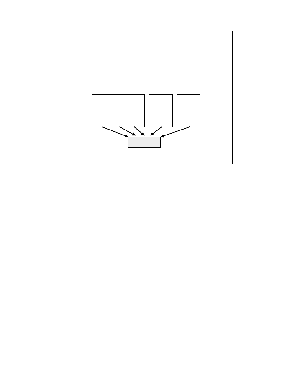
LabVIEW Advanced 1 Course Manual
91
© National Instruments Corporation
Multithreading
Multithreading extends the idea of multitasking into applications, so that specific
tasks within a single application can be subdivided into individual threads, each of
which can theoretically be executed in parallel. The operating system can then
divide processing time not only between different applications, but also between
each thread within an application. For example, Microsoft Word can separate the
printing of a document from the job of saving it to a file as well as from running
the editing window.
In another example, a multithreaded LabVIEW program written in version 5.0
might be divided into three threads—a user interface thread, a data acquisition
thread, and an instrument control thread—each of which can be assigned a
priority and operate independently. Thus, multithreaded applications can have
multiple tasks progressing in parallel along with other applications. The operating
system divides processing time on the different threads similar to the way it
divides processing time among entire applications in an exclusively multitasking
system.
LV Adv I 91
What Is Multithreading?
• Single application can have separate threads
that each get a time slice from the CPU
LabVIEW
Task 1 Task 2 Task 3
App 1
Task 1
Task 2
Task 3
App 2
Task 1
Task 2
Task 3
CPU
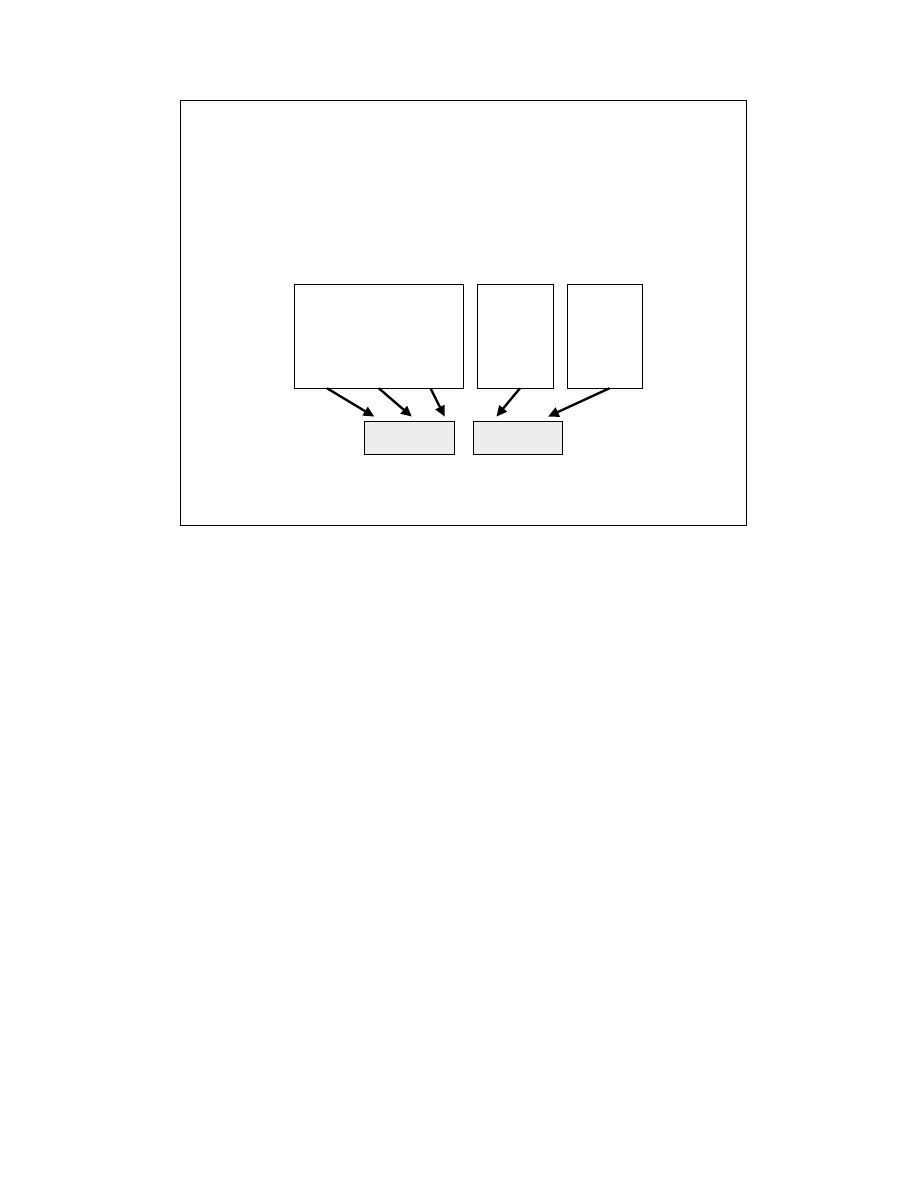
LabVIEW Advanced 1 Course Manual
92
© National Instruments Corporation
Multiprocessing
Multiprocessing refers to two or more processors in one computer. Each processor can
simultaneously execute a separate thread. In a symmetric multiprocessing system, the
operating system automatically uses all of the processors in the computer to run any
threads. Multithreaded programs with parallel executing threads can take full
advantage of any number of processors within the system. With multiprocessing
power, your multithreaded application can run multiple threads simultaneously,
finishing more tasks in less time.
While multiprocessor computers usually are brought into a project to increase
performance, single-threaded applications may experience little performance
improvement on a new multiprocessor machine. Single-threaded applications use only
one processor at any time. In fact, single-threaded applications may adversely affect
performance through the overhead of the operating system switching the application
from one processor to another. To achieve maximum performance from multithreaded
operating systems and multiprocessor machines, an application must be multithreaded.
LV Adv I 92
What Is Multiprocessing?
• Two or more processors in one computer
LabVIEW
Task 1 Task 2 Task 3
App 1
Task 1
Task 2
Task 3
App 2
Task 1
Task 2
Task 3
CPU 1
CPU 2

LabVIEW Advanced 1 Course Manual
93
© National Instruments Corporation
Operating System Support for Multitasking, Multithreading, and
Multiprocessing
While multithreading technology is not a new concept, only in recent years have
PC users been able to take advantage of this powerful technology. Today,
LabVIEW 5.0 users can create multithreaded applications on Microsoft Windows
NT and Windows 95/98, as well as Concurrent PowerMAX. With the exception
of Windows 95/98, these multithreaded operating systems are capable of running
on multiprocessor computers for maximum execution performance.
While the HP-UX and Solaris1 operating systems use preemptive multitasking,
LabVIEW can take advantage of multithreading on Sun Solaris 2 and Concurrent
PowerMAX. Solaris 1 and HP-UX allow independent processes to timeshare
with each other, but do not allow a single process such as LabVIEW to split itself
into several threads in a single memory address space.
LV Adv I 93
Multithreading Support
• Multitasking
– Macintosh
– Windows 3.1
– Solaris 1
– HP-UX
• Multithreading
– Windows 95/98
– Windows NT*
– Solaris 2*
– Concurrent PowerMAX*
* Multiprocessor capable
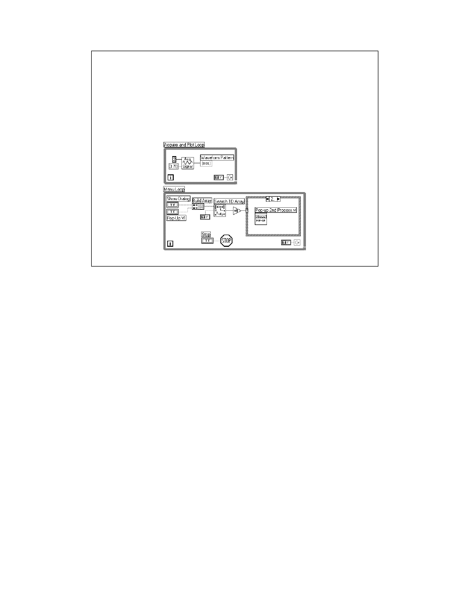
LabVIEW Advanced 1 Course Manual
94
© National Instruments Corporation
How does the LabVIEW execution system work?
VIs built in LabVIEW version 4.1 and earlier run in a single thread. That one
thread handles user interface tasks (attending to keyboard and mouse events,
menus, etc.) and runs the compiled code for the VI. However, within the single
thread, LabVIEW uses a cooperative multitasking methodology to run multiple
tasks concurrently. For example, multiple VIs or parallel loops will run
simultaneously in LabVIEW. Also, if you have an infinite While Loop (a TRUE
constant wired to the conditional terminal), the cooperative multitasking of the
LabVIEW environment allows you to stop the VI by pressing the Abort button.
VIs built in LabVIEW version 5.0 can be run in multiple threads under the
operating systems that support multithreading. The main thread contains all of
the user interface, the editor, and the compiler and uses a cooperative multitasking
system just like previous versions of LabVIEW. Other threads can be used to
perform tasks such as data acquisition, instrument control, and data analysis. If
the multithreading capability of LabVIEW is turned off, VIs are also run using the
cooperative multitasking system of previous versions of LabVIEW.
Chapter 26: Understanding the G Execution System in the G Programming
Reference Manual contains more information about how LabVIEW defines tasks,
threads, and how the execution system operates.
LV Adv I 94
The LabVIEW Execution System
• LabVIEW 4.1 and earlier
– Single thread
– Cooperative multitasking
• LabVIEW 5.0
– Cooperative multitasking
– Multiple threads
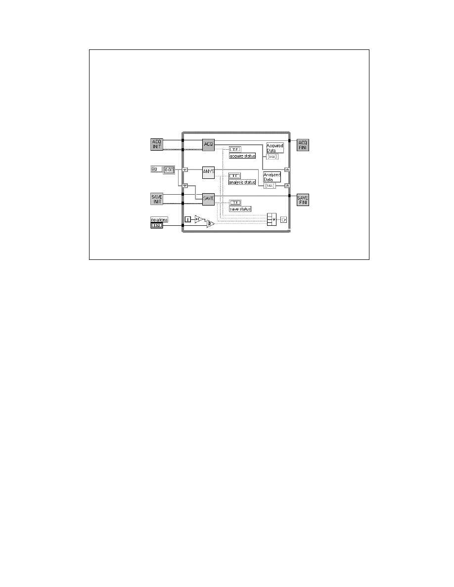
LabVIEW Advanced 1 Course Manual
95
© National Instruments Corporation
Creating a multithreaded application in a traditional programming language can
be difficult. Multithreading involves a new way of programming the parallel
execution of tasks and how they interact with each other versus the traditional
line-by-line execution of code. Although many control-flow, text-based
languages offer libraries for coding multithreaded applications, the very syntax of
the language is sequential and presents difficulties to developers trying to
visualize the parallel execution of code.
As programmers add more threads to their applications, the complexity of
managing those threads jumps exponentially. Creating and synchronizing the
separate threads for acquiring, processing, and displaying data by using events
plus managing the threads and events comprises much of the main program using
a traditional text-based programming language.
However, the graphical nature of LabVIEW makes it very simple to create
parallel tasks. The LabVIEW diagram above can execute in multiple threads.
You do not need to add any additional code for threading, because multithreading
is built into the environment. All of the threads or tasks in the diagram above are
synchronized for each iteration of the loop. As you add functionality to your
LabVIEW program, the thread management is handled automatically.
Another great feature of this built-in multithreading is that you can take your
LabVIEW 5.0 VI to a multiprocessor machine, and the VI will automatically take
advantage of the multiple processors. Each processor can be used to execute a
different thread without your having to add any code or make any other changes
to the VI.
LV Adv I 95
Writing Multithreaded VIs
• No additional code needed
• VI tasks run in multiple threads automatically
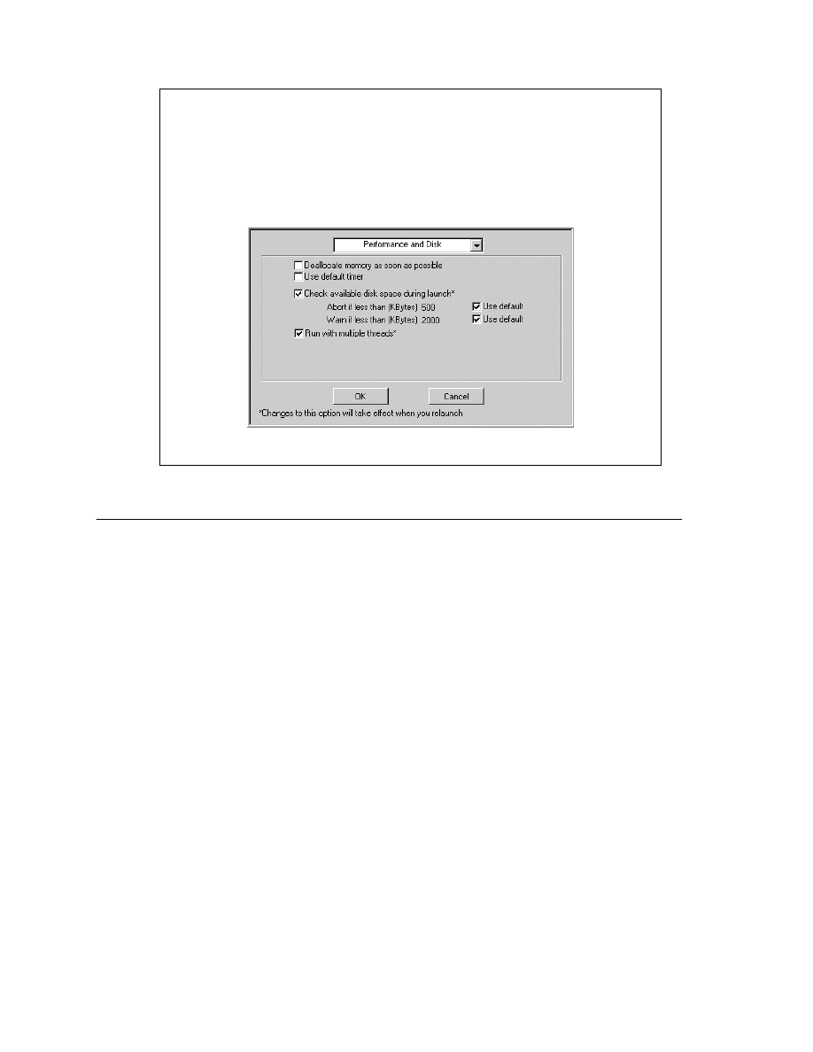
LabVIEW Advanced 1 Course Manual
96
© National Instruments Corporation
B. How to Enable Multithreading in LabVIEW
All of the complex tasks of thread management are transparently built into the
LabVIEW execution system, so that you never need to concern yourself with the
tedious details of thread management. Thus, while text-based programmers must
learn new, complex programming practices to create a multithreaded application,
all LabVIEW 5.0 programs are automatically multithreaded without any code
modifications. To make an existing LabVIEW VI multithreaded, you simply load
your LabVIEW programs into Version 5.0.
To check or set the multithreading state of the LabVIEW environment, go to the
Edit menu and choose Preferences » Performance and Disk. This window is
shown in the slide above. The last option is a checkbox for LabVIEW to “run
with multiple threads.” This box is checked by default. If you uncheck this box,
the next time you launch LabVIEW, it will no longer execute VIs multithreaded.
The environment will cooperatively multitask in a single thread, just as previous
versions of LabVIEW do.
When “run with multiple threads” is selected, several threads are allocated
automatically through the operating system when LabVIEW launches. The
execution threads of LabVIEW will initialize themselves, set up their priorities,
and then sleep while waiting for a VI to be scheduled on their run queue.
LV Adv I 96
Configuring LabVIEW for Multithreading
• Enable multithreading using Preferences (Edit menu)
• Threads are automatically allocated and used

LabVIEW Advanced 1 Course Manual
97
© National Instruments Corporation
LV Adv I 97
Exercise 4-1
Students will open and run the
Thread Exercise VI to
see the effect of enabling multithreading.
Time to complete: 20 min.
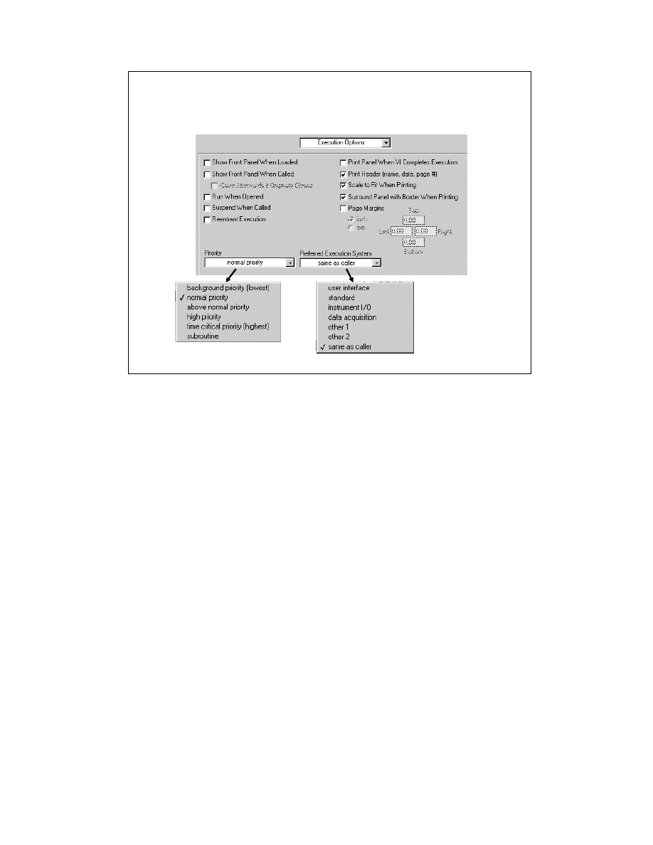
LabVIEW Advanced 1 Course Manual
98
© National Instruments Corporation
Defining and Allocating Threads in LabVIEW
Although LabVIEW automatically handles the multithreading of VI execution,
expert users who want to have specific control over threads can do so from a
straightforward dialog box option. You can select VI Setup from the pop-up
menu on the icon pane and see the settings above from the Execution Options
window. The Priority and Preferred Execution System settings allow you to
control which threads are allocated to a VI.
LabVIEW launches with a default set of execution systems and threads. The idea
behind this set of execution systems is to set up a framework of threads onto
which your VIs can be mapped. This eliminates any need on your part to directly
create, start, or stop threads and still leaves a large amount of flexibility.
The set of priorities and execution systems shown in the options window in the
slide above define the different threads available:
•
One user interface thread is used for screen drawing, keyboard, and mouse
input. This thread is also used for certain types of VI execution, such as
attribute nodes, thread-unsafe CINs and DLLs, debugging, and editing
operations.
•
The “same as caller” execution system is the default setting for all VIs. This
will allow a VI to run in any execution system and is the most efficient
method.
•
Two timer threads are used internally by LabVIEW. (Windows 95/NT/98
allocate one additional thread used internally.)
LV Adv I 98
Configuring Threads for VIs

LabVIEW Advanced 1 Course Manual
99
© National Instruments Corporation
•
Twenty execution threads are allocated per CPU in your system—one thread
for each of the four middle priorities shown above mixed with each of the five
middle execution systems listed above. Subroutine priority VIs always use
the execution system of their calling VI, because staying in the same
execution thread is the most efficient method. Background priority VIs do not
have a thread allocated to them and use the next higher priority threads when
nothing else is available to run.
In a multiprocessor environment, 20 threads per processor will be available to the
LabVIEW execution system. Because thread allocation is dynamic and depends
on which operating system you are using, there is no easy, straightforward way to
see exactly which threads are running at any specific instant.

LabVIEW Advanced 1 Course Manual
100
© National Instruments Corporation
LV Adv I 100
Exercise 4-2
Students will open, run, and compare the Single Thread
and Multiple Threads VIs.
Time to complete: 15 min.

LabVIEW Advanced 1 Course Manual
101
© National Instruments Corporation
C. What are the Benefits of Multithreading?
There are many advantages for a multithreaded environment. You have already
seen a few advantages from the exercises you have done. In exercise 4-1, you saw
that multithreading can improve performance, because operations such as
acquiring or generating data are separated from slower tasks such as panel
updates. In exercise 4-2, you saw that a multithreaded environment is more
deterministic than a single threaded environment. The CPU can be used more
efficiently because other tasks can run if one thread is waiting for an event.
Another example where multithreading provides better system reliability is
performing high-speed data acquisition and display. Screen updates are often
slow related to other operations such as continuous high-speed data acquisition. If
you attempt to acquire very large amounts of data at high speed in a single-
threaded application and display all of that data in a graph on the panel, your data
buffer may overflow because the processor is forced to spend too much time on
the screen update and data is lost. However, in a multithreaded application, the
data acquisition can reside on a different, higher priority thread than the user
interface. The acquisition can continuously run and send data into memory
without interruption while the data is displayed as quickly as possible. The data
acquisition thread will preempt the display thread so you will not lose data.
One of the most promising benefits of multithreaded applications is that it can
harness the power of a multiprocessor environment. Single-threaded applications
will not be able to use multiple processors, but maximum performance can be
achieved in a multithreaded operating system with a multithreaded application in
a multiprocessor machine.
LV Adv I 101
Benefits of Multithreaded Applications
• More efficient CPU use
• Performance increased; more deterministic
• Better system reliability
• Other threads in an application can run while
one is waiting (EX: DAQ, File I/O, user input)
• Multiprocessor environments fully utilized

LabVIEW Advanced 1 Course Manual
102
© National Instruments Corporation
LV Adv I 102
Exercise 4-3
Students will build the
Multiple Tasks
VI to
examine the effects of multithreading.
Time to complete: 25 min.

LabVIEW Advanced 1 Course Manual
103
© National Instruments Corporation
D. When You Should Avoid Multithreading
Many advantages exist for multithreaded applications. Increased performance and
more efficient CPU use are just two of them. LabVIEW makes it extremely easy to
write multithreaded VIs and to assign those threads different priorities. However,
there are some situations where multithreading can decrease performance. This
section will show you how to optimize the VI performance with regard to
multithreading issues.
Reasons Not to Use Multithreading in Your VI
•
If your application is written so that everything happens sequentially. For
example, if your application consists of open file -> read file -> close file,
multithreading will not help. Multithreading can help performance only when
the tasks run in parallel and can operate independently.
•
When your application does excessive thread swaps. Thread swaps are costly,
especially on a single-CPU system, because multiple threads still must share
time on the CPU. Therefore, several CPU-intensive threads running in parallel
will not perform their computations faster just because they are threaded.
Those threads may run slower because extra time is spent by the operating
system switching between threads. Another example is of one or more subVIs
that are all set to run in separate threads than the calling VI. The CPU could
spend more time switching between threads than running the application if the
subVIs are called many times and continually transfer data back and forth with
each other and the main VI.
LV Adv I 103
When to Avoid Multithreading
• Tasks are sequential
• Thread swaps are costly
• High-priority threads are starving other
threads
• Limited resources in system
• Heavy use of thread-unsafe CINs and DLLs
• Most tasks access the user interface thread
• Deadlocked threads need to share data
• Memory is limited

LabVIEW Advanced 1 Course Manual
104
© National Instruments Corporation
•
High-priority threads can starve other threads from CPU time. Use
priorities cautiously, because lower priority tasks easily get starved
for time by higher priority tasks. If the higher priority tasks are
designed to run for long periods, lower priority tasks are not going to
execute unless the higher priority task periodically waits or performs
I/O so it is taken off the execution queue. When using priorities,
consider adding waits to the less time-critical sections of your
diagrams to free up time. In most cases, do not change the priority
of a VI from the default in VI Setup.
•
System resources limit the number of threads that can be allocated.
Threads use system resources, so there is a limit to the number of
threads you can create depending upon the system configuration.
Also, running with multiple threads can affect other applications.
Each thread is scheduled independently by the operating system, so
applications with more threads will tend to get more CPU time.
Therefore, other applications may appear to run more slowly if
LabVIEW is running several VIs in different threads simultaneously.
•
LabVIEW 3.x and 4.x VIs may run slower on a multithreaded
system if they call Code Interface Nodes (CINs) or Dynamic Link
Libraries (DLLs). By default, when a LabVIEW 3.x/4.x CIN or
DLL is loaded into LabVIEW 5.0, the external code is considered
thread-unsafe and is colored orange. Thread-unsafe CINs and DLLs
are always run in the user interface thread to ensure that those nodes
can be called only from one thread at a time and thus protect data
integrity. Therefore, when a VI is running, the execution system
must switch between the normal execution system and the user
interface thread and back again each time that CIN or DLL is called.
This can add a large amount of overhead to the execution speed.
Module 3: Calling External Functions of this course describes how
you can make a CIN or DLL thread safe.

LabVIEW Advanced 1 Course Manual
105
© National Instruments Corporation
The LabVIEW functions, VIs, and operations listed above must run in the user
interface node. If the main VI repeatedly calls any of these nodes, performance
might suffer if the main VI is running in another execution thread and must
constantly switch back and forth to the user interface thread. What can you do
about these operations that need the user interface execution system?
The VI Server functions allow you to open, run, close, and operate LabVIEW
VIs dynamically. See Module 2: Connectivity in this course for more
information about the VI Server.
Attribute nodes, menu control VIs, and dialog boxes perform user interface-
oriented work. There is little advantage to separating them from the user
interface, so any subVI that uses these nodes extensively should be configured
to run in the user interface execution system in VI Setup to minimize the
transition overhead. Try to use single attribute nodes with several inputs and
outputs rather than multiple attribute nodes with only one input/output each.
Thread-unsafe CINs and DLLs also add overhead, which you can avoid by
either making that external code thread-safe as described in Module 3 of this
course or setting the VI that calls them to run in the user interface execution
system in VI Setup.
Multithreaded applications can be debugged using the LabVIEW debugging
tools. However, because the debugging tools themselves exist in the user
interface thread, the multithreaded state of the VI is not reflected accurately
when the debugging tools are used.
LV Adv I 105
Operations that Require the User
Interface Thread
• Attribute nodes
• Menu control VIs
• VI Server--Property Node and Invoke
Node
• Thread-unsafe CINs and DLLs
• Debugging code (probes, single
stepping, execution highlighting)
• Dialog boxes
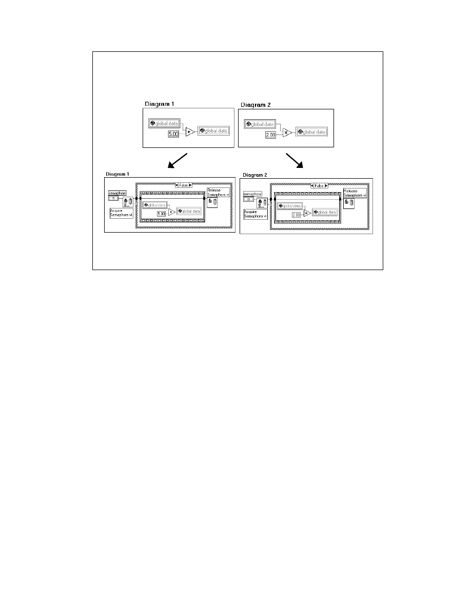
LabVIEW Advanced 1 Course Manual
106
© National Instruments Corporation
How to share and protect data between multiple threads is one problem that is
unique to a multithreaded environment. In the previous lesson, you learned that
race conditions with global and local variables can lead to unexpected data values.
Multithreading can lead to race conditions as well when different threads
manipulate the same data.
Consider the top diagrams in the slide above. The first diagram reads a global
numeric, adds five to it, and writes the value back to the global numeric. The
second diagram reads the global numeric, multiplies it by two, and writes the value
back to the global. If these two operations are running in different threads
simultaneously, what value will the global numeric contain when both diagrams
are finished executing? You cannot be sure unless you protect access to that global
variable.
A Semaphore is used in the bottom diagrams to limit access to the global variable.
If you remember from the last lesson, a semaphore is useful for protecting two or
more critical sections of code that should not be called concurrently. Semaphores
are located in the Advanced » Synchronization palette. Before entering a critical
section of code—such as reading and writing to the global numeric—the thread
must acquire a semaphore. If no thread is already in the critical section, the thread
proceeds to enter that part of the diagram immediately. This thread must release
the semaphore once the critical section is complete. Other threads that want to
enter the critical section must wait until the first thread releases the semaphore.
You can use the other Synchronization VIs to protect global data as well. Refer to
the previous lesson and to the examples in LabVIEW for more information.
LV Adv I 106
When Threads Need to Share Data
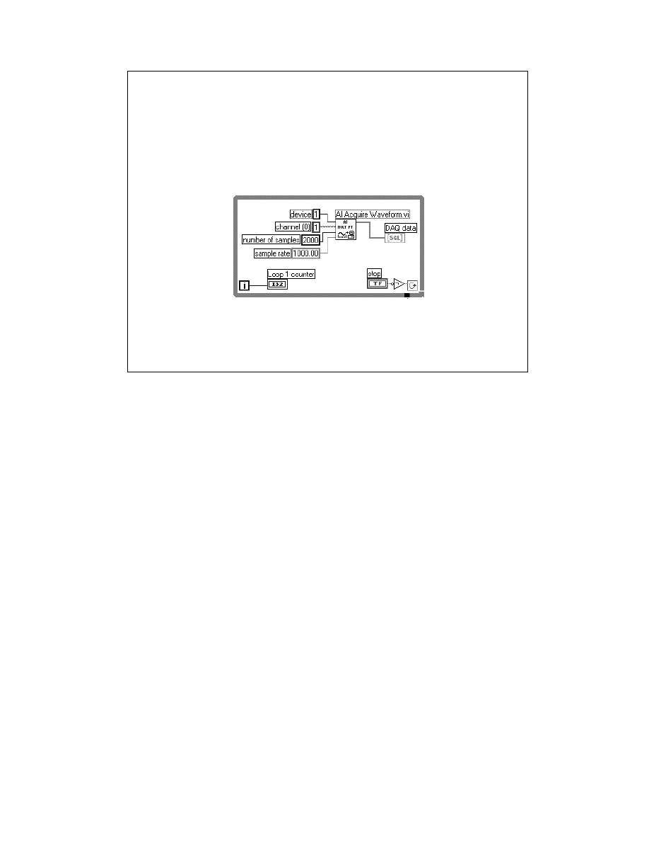
LabVIEW Advanced 1 Course Manual
107
© National Instruments Corporation
How does multithreaded execution affect memory use?
Multithreaded execution of VIs can cause extra copies of data buffers that
are not needed when the VIs run in a single thread. For example, you
already know that the diagram can execute independently from the user
interface. However, what happens when the diagram needs to send data to
the user interface or a user changes a control that affects the user interface?
Every control and indicator on the panel will have an extra transfer buffer so
the different threads can pass data back and forth.
In the second lesson of this module, you learned that you should avoid
displaying large strings and arrays on the front panel of a VI to avoid the
extra copy of that string or array in memory. Now you will get two copies
of those objects when LabVIEW is configured to run in multiple threads, so
you should be extra careful about displaying large data sets on the panel.
The only exception to the transfer buffers are waveform charts. Charts have
a history buffer of data that is always available, and LabVIEW uses this
history buffer as the transfer buffer between threads. Therefore, you will not
miss data or make extra copies when you use a chart instead of a graph.
LV Adv I 107
Memory Use in a Multithreaded Application
• Transfer buffers are required to pass data from
the execution thread to the user interface thread
• The chart history acts as the transfer buffer

LabVIEW Advanced 1 Course Manual
108
© National Instruments Corporation
Troubleshooting Performance Problems
If you have tried all the methods described in previous lessons and you still have
a problem with VI performance, here are some things you can try:
•
Disable the “Run in multiple threads” option in Edit » Preferences »
Performance and Disk. Restart LabVIEW and run the VI to see if the
performance changes to determine if the problem is related to threads.
•
Look for thread-unsafe CINs and DLLs. They will appear as orange instead
of the regular yellow color. Multiple calls to thread-unsafe CINs and DLLs
can cause a large performance hit.
•
Look for VIs that are running with different priorities and execution systems.
You might have the situation where a higher-priority thread is getting all the
CPU time and the other threads are starving for resources.
•
If the indicators on the panel are not displaying data, you should enable the
“Synchronous Display” option from their pop-up menu. The user interface
thread might not be able to keep up with the execution thread of the diagram
and the indicators will not update.
•
If you press the red abort button while a VI is executing, you could see a
dialog box that says “Waiting for reset…” and the VI will appear to hang in
this state. This means that one of the executing threads was unable to
complete immediately and you should wait for functions to timeout.
Sometimes the VI will be hung and you will need to kill the LabVIEW
process. This can happen if you abort while the VI is running a DLL.
Aborting threads can be a complicated internal process, and you should
avoid pressing the abort button while running in multiple threads.
LV Adv I 108
Troubleshooting Performance Problems
• Disable multithreading to determine if there
is a thread problem
• Look for orange CINs and DLLs
• Look for VIs with different priorities and
execution systems
• Enable synchronous display on indicators
• Be aware of the “waiting for reset”

LabVIEW Advanced 1 Course Manual
109
© National Instruments Corporation
LV Adv I 109
Exercise 4-4
Students will observe and optimize the
Thread Performance VI.
Time to complete: 30 min.

LabVIEW Advanced 1 Course Manual
110
© National Instruments Corporation
LV Adv I 110
Summary
• Multitasking is when different applications are run
simultaneously. Multithreading is when different tasks
within the same application can run simultaneously.
• LabVIEW 5.0 and later is capable of multithreaded
execution on the Windows 95/NT/98, Solaris 2, and
Concurrent PowerMAX operating systems.
• You do not need to rewrite any code to make your VIs
multithreaded. That option is enabled by default in Edit »
Preferences » Performance and Disk.
• You can configure VIs to run with different priorities and
different execution systems from VI Setup » Execution
Options.
• Multithreaded execution in general offers many benefits for
VI performance and system resource management.
• Multithreaded execution might decrease performance if it is
used incorrectly.

LabVIEW Advanced 1 Course Manual
111
© National Instruments Corporation
Performance Issues—Where to Go from Here
The best way to improve memory management and multithreaded performance
issues is to use good programming style. The books listed above describe how
LabVIEW works and how to program with good style. All of these references
can be found in the National Instruments catalog and on the web site at
www.natinst.com
.
LV Adv I 111
Best Way to Improve Memory Usage
is to Use Good Style
The
LabVIEW User Manual
The
G Programming Reference Manual
The
LabVIEW with Style
document
LabVIEW Application Notes
LabVIEW Technical Resource
(LTR) Newsletter
LabVIEW Graphical Programming
and
LabVIEW Power Programming
by Gary W. Johnson
LabVIEW for Everyone
by Lisa K. Wells and
Jeffrey Travis

LabVIEW Advanced 1 Course Manual
112
© National Instruments Corporation
Another good resource for LabVIEW information is the info-labview user-
sponsored Internet forum.
•
Info-labview is an Internet mailing list where LabVIEW users around the
world post questions, trade VIs, describe their applications, and discuss all
aspects of LabVIEW programming.
•
To subscribe to info-labview, just send an email to
info-labview-request@pica.army.mil
•
Include in your message what your email address is and if you want to
subscribe to a daily digest or individual messages (~30/day). If you want to
post a question to the group, send your email to:
info-labview@pica.army.mil
LV Adv I 112
• Presentations by LabVIEW software engineers at
LabVIEW user group meetings, NI User
Symposia, and NI Developers’ Conferences
• Info-LabVIEW user-sponsored Internet mailing
list
–
To subscribe, send your email address to
info-labview-request@pica.army.mil
–
Specify whether you want individual
messages or a daily digest
•
Info-LabVIEW FTP Site at
ftp.pica.army.mil
Where to Get More Information

LabVIEW Advanced 1 Course Manual
113
© National Instruments Corporation
Introduction
Connectivity between multiple applications allows one or more applications to use the
services of another application. For example, a data collection application such as
LabVIEW, running on a dedicated computer, can provide information to a database or
spreadsheet program directly. The applications can run on the same computer, or on
separate computers connected over a hardware network such as Ethernet.
For two processes to communicate, they must use a common protocol. A connection
protocol lets you specify the data you want to send or receive and the location of the
destination or source, without worrying about how the data gets there. This module
describes the different protocols and methods that LabVIEW supports for transferring
data to and from other applications.
Course Description
The LabVIEW Connectivity module teaches you to use the different protocols that
LabVIEW supports for interapplication communication. The course is divided into
lessons, each covering a topic or a set of topics. Each lesson consists of:
•
An introduction that describes the lesson’s purpose and what you will learn.
•
A discussion of the topics
•
A set of exercises to reinforce the topics presented in the discussion.
•
A set of additional exercises to be done if time permits.
•
A summary that outlines important concepts and skills taught in the lesson.
LV Adv I 113
LabVIEW Advanced I Course
Module 2
Connectivity
TM
National Instruments
11500 N. MoPac Expressway
Austin, Texas 78759
(512) 683-0100

LabVIEW Advanced 1 Course Manual
114
© National Instruments Corporation
LV Adv I 114
National Instruments Technical Support Options
Telephone Support (USA):
Fax
.............................................................
(512) 683-5678
Telephone
...........................................
(512)
683-8248
Fax-on-Demand: 24-hour information retrieval system with
a library of documents
.............…
(512) 683-1111
Internet Support:
Web Support - searchable Knowledgebase, support
documents, and files
................
http://www.natinst.com
.......................................................
support@natinst.com
FTP - contains support files and documents to download
FTP Site:
ftp.natinst.com
login:
anonymous
password:
your Internet address
Listed above are the various ways you can contact National Instruments for technical support.

LabVIEW Advanced 1 Course Manual
115
© National Instruments Corporation
LV Adv I 115
Course Goals
• Use TCP/IP functions and VIs in LabVIEW to
communicate with other applications and over a
network.
• Use UDP VIs in LabVIEW to transfer data to another
computer.
• Use the VI Server functions to load and operate a VI or
LabVIEW programmatically.
• Understand the importance of strictly-typed VI Refnums.
• Understand LabVIEW’s ActiveX automation capabilities.
• Understand LabVIEW’s ActiveX container capabilities.
• Use ActiveX automation client VIs to access an
automation server like Excel.
• Understand how automation clients access LabVIEW’s
automation servers.
This course prepares you for the items listed above.
Additional optional exercises at the end of the lessons challenge you to enhance the basic
application features. Specific details regarding the program capabilities are in the relevant
exercises.

LabVIEW Advanced 1 Course Manual
116
© National Instruments Corporation
LV Adv I 116
Course Non-Goals
• To teach LabVIEW basics
• To teach programming theory
• To discuss every built-in LabVIEW object,
function, or library VI
• The development of a complete
application for any student in the class
• To discuss every aspect of ActiveX
and OLE.
It is not the purpose of this course to discuss any of the items listed above.
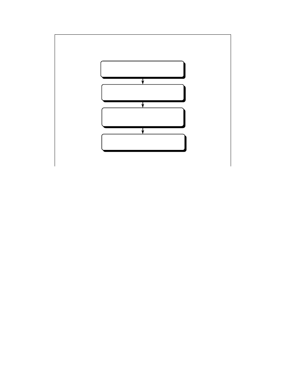
LabVIEW Advanced 1 Course Manual
117
© National Instruments Corporation
LV Adv I 117
Course Outline
TCP/IP Communications
VI Server
ActiveX Automation Server
ActiveX Automation
Client and Container
The LabVIEW Connectivity module is a one-day course. Here is a rough timeframe for the
material covered:
Lesson 1:
TCP/IP Communications
Break
Lesson 2:
VI Server
Lunch
Lesson 3:
ActiveX Automation Server
Break
Lesson 4:
ActiveX Automation Client and Container
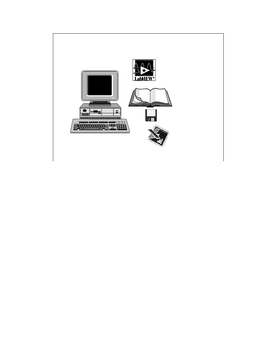
LabVIEW Advanced 1 Course Manual
118
© National Instruments Corporation
LV Adv I 118
Equipment Needed for this Module
Computer running Windows 95/NT/98
LabVIEW for Windows
ver. 5.0 or later
LabVIEW Advanced I
Course Manual
LabVIEW Advanced I
Course Disks
Microsoft Excel 97
Items You Will Need for this Course Module:
•
Computer running Windows 95/NT/98
•
One null-modem Ethernet cable connecting your computer to another
•
Networking support software to support the protocols covered in this module for the
operating system you are using
•
LabVIEW for Windows Full Development System, ver. 5.0 or later
•
LabVIEW Advanced I Course Manual and Disks
•
Optional—A word processing application such as Notepad or Wordpad
•
Optional—Microsoft Visual C++ 5.0
•
Microsoft Excel 97
•
AT-MIO-16E-2 DAQ board configured as Board ID 1 using the NI-DAQ configuration
utility (used for only two exercises)
•
DAQ Signal Accessory (used for only two exercises)
Install the course software by inserting the first course disk and double-clicking on the file
Module2.exe.
Extract the contents of this self-extracting archive into your
C:\
directory.
All of the files you need will be installed into the
C:\Exercises\LV_AdvI
directory. The
solutions to all the exercises will be installed into the
C:\Solutions\LV_AdvI
directory.
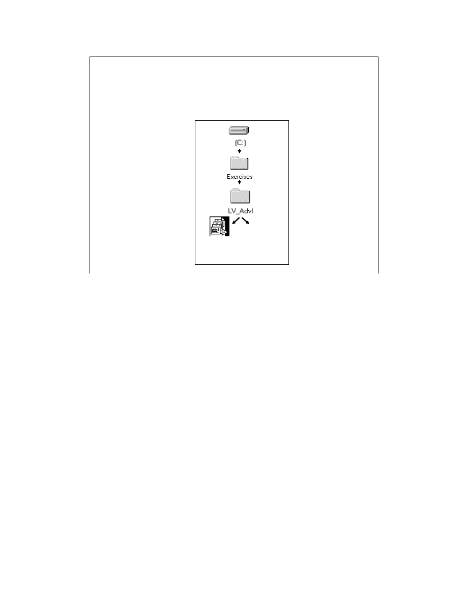
LabVIEW Advanced 1 Course Manual
119
© National Instruments Corporation
LV Adv I 119
Hands-On Exercises
• Exercises reinforce the topics presented
• Save exercises into the VI library shown here:
comclass.llb
Acquire.exe
Acquire.xls
Acquire.cpp
Vccalc.exe
vccalc.tlb
vccalc.reg
wave.xle
sin.xls

LabVIEW Advanced 1 Course Manual
120
© National Instruments Corporation
Several communication protocols are built into LabVIEW. This lesson discusses TCP/IP and
how you can use the LabVIEW TCP and UDP VIs to communicate with applications on
other computers connected across a network.
LV Adv I 120
Lesson 1
TCP/IP
You Will Learn:
• About the history and requirements of TCP/IP
• About the TCP/IP VIs and functions
• About UDP and LabVIEW

LabVIEW Advanced 1 Course Manual
121
© National Instruments Corporation
For two processes to communicate, a common communications language—or protocol—must
be used. A communications protocol lets you specify the data that you want to send or receive
and the location of the destination or source, without worrying about how the data gets there.
The protocol and network drivers take care of transferring data across the network.
Several networking protocols have emerged as acceptable standards for communications. In
general, one protocol is not compatible with another. Thus, one of the first things you must do is
decide which protocol to use. To communicate with an existing, off-the-shelf application, you
must work within the protocols supported by that application.
TCP/IP is a suite of communication protocols originally developed in the 1960s by the U.S.
Department of Defense as a means for different manufacturer’s computers to communicate
information. By the early 1970s, the Advanced Research Projects Agency (ARPA) had
ARPAnet, a network that linked major research universities. ARPA developed the TCP/IP
protocols and implemented them on interconnected networks. This allowed communication
between a number of computer systems, including VAX, IBM mainframes, and others. Since its
development, TCP/IP has become widely accepted and is available on a number of computer
systems. It is also the LabVIEW networking protocol that is available on all the platforms that
LabVIEW supports.
TCP/IP enables communication over single networks or multiple inter-connected
networks(known as an internetwork or Internet). The individual networks can be separated by
great geographical distances. TCP/IP routes data from one network or Internet computer to
another. Because TCP/IP is available on most computers, it can transfer information between
diverse systems.
LV Adv I 121
Introduction and History of TCP/IP
• Transmission Control Protocol/Internet Protocol
.
• 1960s
—
Developed by DOD to communicate between
different manufacturer’s computers
.
• 1970s
—
ARPA has a network that linked major research
universities
.
• UC Berkeley incorporated TCP/IP into UNIX
.
• TCP/IP becomes widely accepted and universities
distribute TCP/IP applications for free
.
• TCP/IP is the communications protocol supported on all
LabVIEW platforms
.
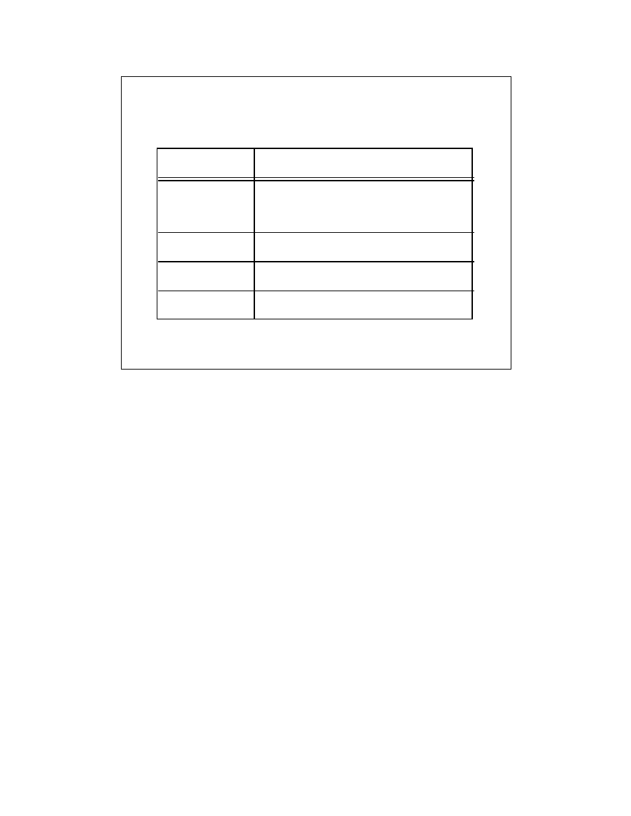
LabVIEW Advanced 1 Course Manual
122
© National Instruments Corporation
The name TCP/IP comes from two of the best known protocols in the suite, the Transmission
Control Protocol (TCP) and the Internet Protocol (IP). TCP, IP, and the User Datagram Protocol
(UDP) are the basic tools for network communication. Four layers of the TCP/IP protocol are
shown in the table on the slide above.
The Address Resolution Protocol (ARP) maps Ethernet to TCP/IP internet addresses and was
incorporated into TCP/IP in 1982. The Internet Protocol (IP) transmits data across the network.
This low-level protocol takes data of a limited size and sends it as a datagram across the
network. IP is rarely used directly by applications, because it does not guarantee that the data
will arrive at the other end. Also, when you send several datagrams, they sometimes arrive out
of order, or are delivered multiple times, depending on how the network transfer occurs.
TCP is a higher level protocol that uses IP to transfer data. TCP is connection oriented. It
establishes a session between the user processes, breaks data into components that IP can
manage, encapsulates the information, transmits the datagrams, and tracks the datagram
progress. Lost datagrams are retransmitted and data will arrive in order and without duplication.
For these reasons, TCP is usually the best choice for network applications.
UDP is for applications that do not need all the power of TCP. UDP is built on IP, but does not
have as much overhead and does not track datagrams the way that TCP does.
The IP protocol, on which both TCP and UDP are based, is responsible for error checking.
Hence, both the protocols support error checking, and a data packet is not delivered unless it
passes error checks.
LV Adv I 122
Protocol Layers
Layer
Protocol
Application,
Presentation,
or Session
SMTP
(Simple Mail Transfer Protocol)
FTP
(File Transfer Protocol)
Telnet
Transport
Network
Datalink (HW)
TCP, UDP
IP, ARP
(Address Resolution Protocol)
Ethernet

LabVIEW Advanced 1 Course Manual
123
© National Instruments Corporation
Each host on an IP network has a unique 32-bit Internet address. This address identifies the
network on the Internet to which the host is attached, and the specific computer on that network.
You use this address to identify the sender or receiver of the data. IP places the address in the
datagram headers so that each datagram is routed correctly. One way of describing this 32-bit
address is in IP dotted decimal notation. This divides the 32-bit address into four 8-bit numbers.
The address is written as the four integers, separated by decimal points. An example is shown in
the slide above.
Another way of using the 32-bit address is by using names that are mapped to the IP address.
Network drivers usually perform this mapping by consulting a local host’s file that contains
name-to-address mappings, or by consulting a larger database using the Domain Name System
to query other computer systems for the address of a given name. Your network configuration
dictates the exact mechanism for this process, which is known as hostname resolution.
In establishing TCP connections, you must specify both the address and a port at that address. A
port is represented by a number between 0 and 65535. With UNIX, port numbers less than 1024
are reserved for privileged applications. Different ports at a given address identify different
services at that address, making it easier to manage multiple simultaneous connections.
LV Adv I 123
Internet Addresses and Ports
32-bit Address
10000100 00001101 00000010 00011110
= 132.13.2.30
or hostname resolution (Domain Name System)
Port
Numbers between 0 and 65535
Specifies a service at the address
Numbers less than 1024 are reserved under
UNIX for privileged applications.

LabVIEW Advanced 1 Course Manual
124
© National Instruments Corporation
Before you can use TCP/IP, you need to make sure that you have the correct hardware and software. The
setup varies, depending on the computer you use.
Windows 95/NT/98
TCP support is built into these operating systems, although you must install a network board and its low-
level driver in your machine.
Windows 3.x
To use TCP/IP, you must install an Ethernet board along with its low-level driver. In addition, you must
purchase and install TCP/IP software that includes a Windows Sockets (WinSock) DLL conforming to
standard 1.1. WinSock is a standard interface that enables application communication with a variety of
network drivers. Several vendors provide network software that includes the WinSock DLL. Install the
Ethernet board, the board drivers, and the WinSock DLL according to the software vendor instructions.
SUN and HP-UX
TCP/IP support is built in. No additional setup for communicating through LabVIEW is necessary,
assuming your network is configured properly.
Macintosh and Power Macintosh
TCP/IP is built into the Macintosh operating system version 7.5 and later. To use TCP/IP with an earlier
system, you need to install the MacTCP driver software, available from the Apple Programmer
Developer Association(APDA).
LV Adv I 124
TCP/IP System Requirements
•
Windows 95/NT/98, Sun, and HP-UX
:
All the TCP/IP
software support is built into the operating system. Need
Ethernet hardware connection.
•
Windows 3.x
:
Must install TCP/IP software that includes a
Windows Sockets DLL conforming to standard 1.1. Also,
must have Ethernet hardware
.
•
Macintosh and PowerMac
:
TCP/IP software is built into
the MacOS version 7.5 and later. Earlier versions of MacOS
can get MacTCP from APDA. Must have Ethernet hardware
connection
.
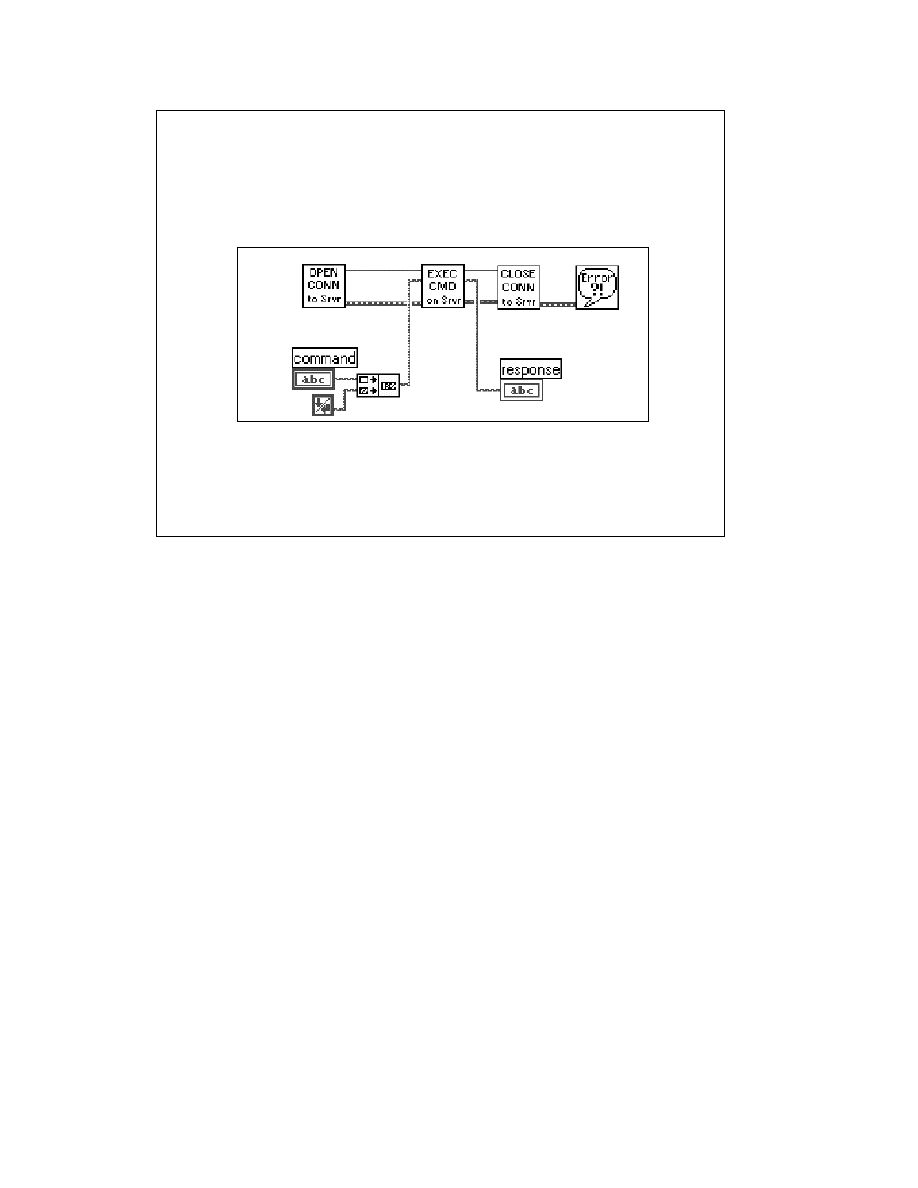
LabVIEW Advanced 1 Course Manual
125
© National Instruments Corporation
The client/server model is a common model for networked applications. In this model, one set
of processes (clients) requests services from another set of processes (servers).
Another way to think about clients and servers is to compare them to a restaurant. The waiter is
a server and you are a client. You ask for the menu, order a meal, and make requests of the
waiter similar to the way a client communicates with a server on a network. Your computer acts
as a server when it provides data to other computers or applications on request, and it acts as a
client when it requests another application—such as a database program—to record acquired
data.
The diagram on the slide above shows the simplified model for a client in LabVIEW. These are
not the TCP/IP VIs in LabVIEW. They represent the major steps in the flow chart model for
TCP/IP communication.
1.
LabVIEW opens a connection to a server.
2.
It sends commands to the server.
3.
It receives responses from the server.
4.
Finally, it closes the connection and reports any errors that occurred during the
communication process.
For higher performance, you can process multiple commands once the connection is open. After
the commands are executed, you can close the connection. This basic block diagram structure
serves as a model and is used elsewhere in this course to demonstrate how to implement a given
protocol in LabVIEW. The next section applies to TCP/IP communication using LabVIEW.
LV Adv I 125
Client Model
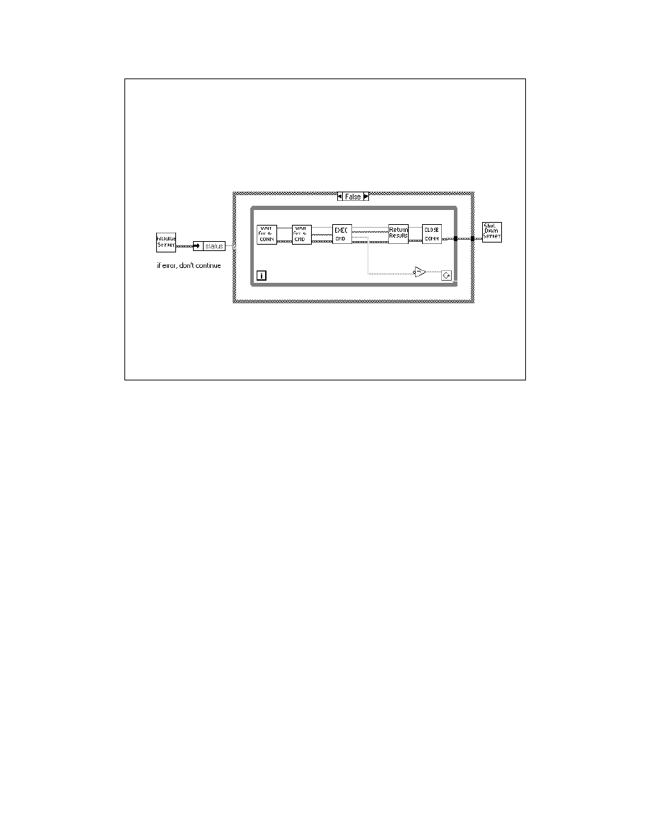
LabVIEW Advanced 1 Course Manual
126
© National Instruments Corporation
.The flow chart in the diagram above shows a simplified model for a server in LabVIEW. Again,
these are not the TCP/IP VIs, just the major steps that should be performed.
1.
LabVIEW first initializes the server.
2.
If the initialization is successful, LabVIEW goes into a loop, where it waits for a connection.
3.
Once the connection is made, LabVIEW waits to receive a command.
4.
LabVIEW executes the command and returns the results.
5.
The connection is then closed.
LabVIEW repeats this entire process until it is shut down remotely by sending a command to
end the VI. This VI does not report errors. It may send back a response indicating that a
command is invalid, but it does not display a dialog when an error occurs. Because a server
might be unattended, consider carefully how the server should handle errors. You probably will
not want a dialog box to be displayed, because that requires user interaction at the server
(someone would need to press the OK button). However, you might want LabVIEW to write a
log of transactions and errors to a file or a string.
LV Adv I 126
Server Model
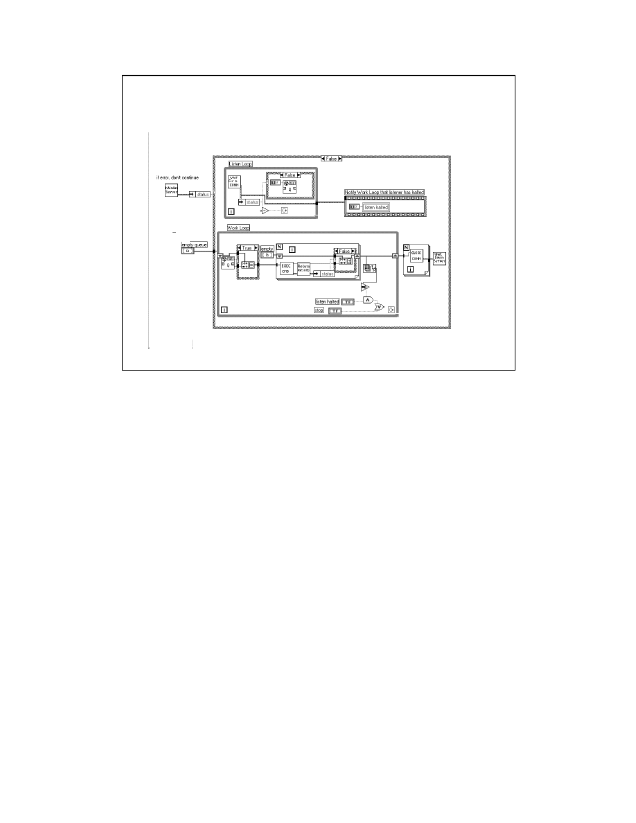
LabVIEW Advanced 1 Course Manual
127
© National Instruments Corporation
You can increase performance by allowing the connection to stay open. You can receive
multiple commands this way, but it also blocks other clients from connecting until the current
client disconnects. You can restructure the block diagram to handle multiple clients
simultaneously as shown in the slide above.
The diagram above uses the LabVIEW multitasking capabilities to run two loops
simultaneously. The top loop continuously waits for a connection and then adds the connection
to a synchronized queue. The bottom loop checks each of the open connections and executes
any commands that have been received. If an error occurs on one of the connections, the
connection is disconnected. When the user aborts the server, all open connections are closed.
LV Adv I 127
Server Model cont....

LabVIEW Advanced 1 Course Manual
128
© National Instruments Corporation
LV Adv I 128
Exercise 1-1
Students will determine the IP address
for their computers.
Time to complete: 10 min.
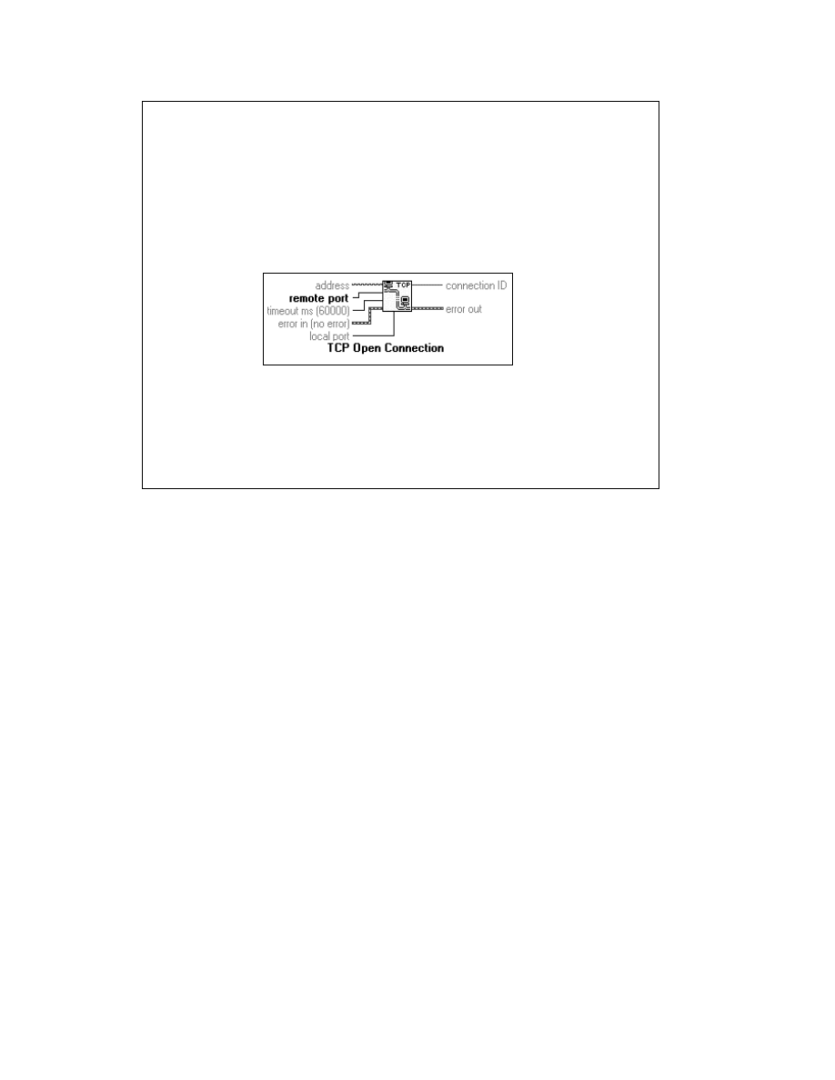
LabVIEW Advanced 1 Course Manual
129
© National Instruments Corporation
The previous slides discussed the background information about TCP and IP, discussed basic
terminology, and described the client and server models of network communication. This
section describes the TCP/IP VIs and functions in LabVIEW and how you can use LabVIEW as
a client or server application.
The TCP VIs and functions are located in Functions » Communication.
The TCP Open Connection function is used on the client machine to open a connection to a
server using the specified Internet address and port for the server. If the connection is not
established in the specified timeout period, the function completes and returns an error.
connection ID is a network connection refnum that uniquely identifies the TCP connection.
error in and error out clusters describe any error conditions.
The address identifies a computer on the network and can be expressed in IP dot notation or as
the hostname. The port is an additional number that identifies a communication channel on the
computer that the server uses to listen for communication requests. When you create a TCP
server, you specify the port that you want the server to use for communication. If the connection
is successful, the TCP Open Connection VI returns a connection ID that uniquely identifies
that connection. You will use this connection ID to refer to the connection in subsequent
VI calls.
LV Adv I 129
The TCP/IP Functions
Located in - Functions » Communication » TCP
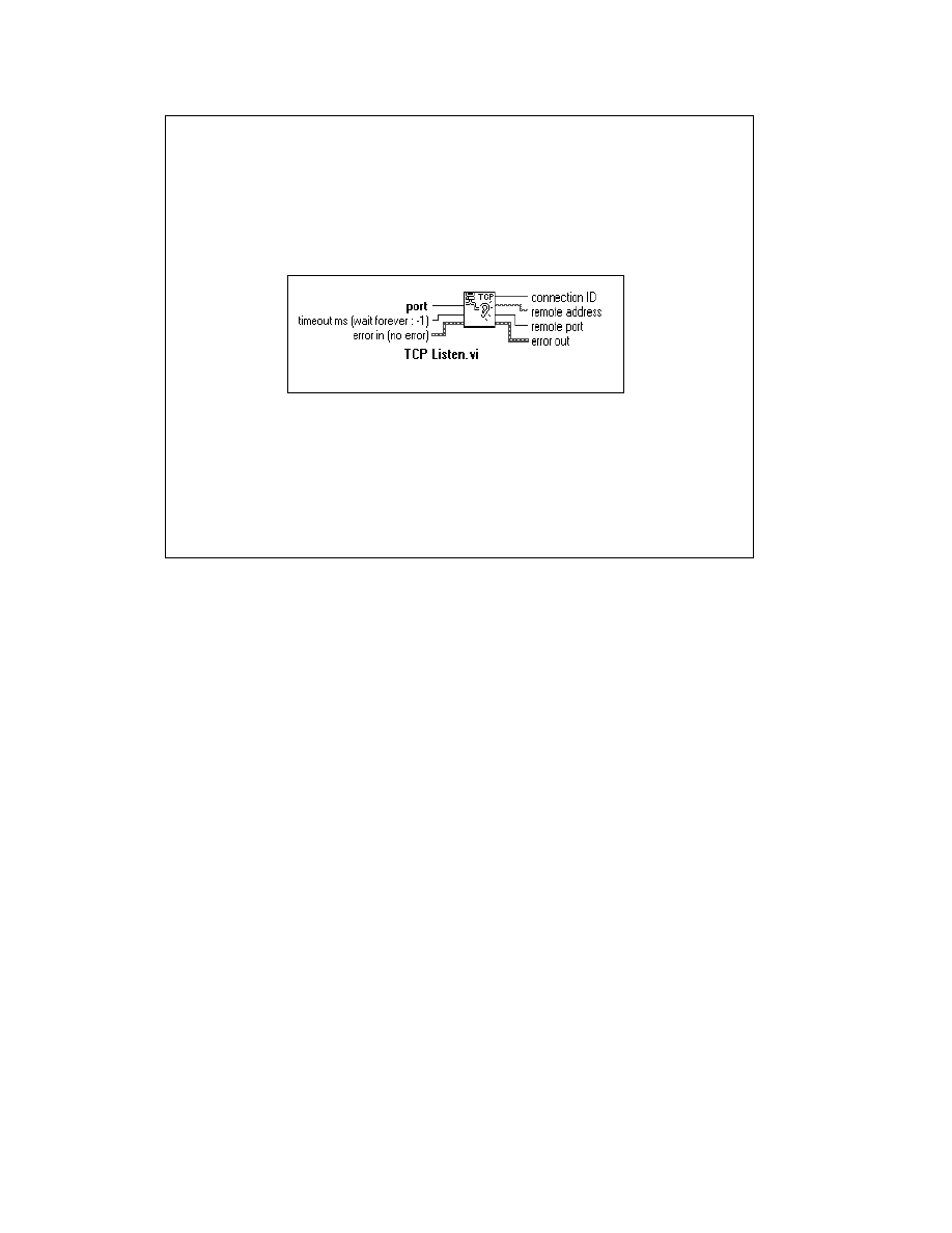
LabVIEW Advanced 1 Course Manual
130
© National Instruments Corporation
TCP Listen VI
The TCP Listen VI is on the server machine and waits for an accepted TCP connection at the specified
port. If the connection is not established in the specified timeout period, the VI returns an error.
connection ID is a network connection refnum that uniquely identifies the TCP connection. remote
address and remote port describe the remote machine associated with the TCP connection. Error in
and error out clusters describe any error conditions.
You can use two methods to wait for an incoming connection. With the first method, you use the TCP
Listen VI (as shown above) to create a listener and wait for an accepted TCP connection at a specified
port. If the connection is successful, the VI returns a connection ID and the address and port of the
remote TCP.
The second method is used in the example Date Server.vi located in EXAMPLES »
COMM » TCPEX.LLB. First, use the TCP Create Listener VI to create a listener on a computer that
will act as a server. Then use the Wait on Listener function to listen for and accept new connections.
Wait on Listener returns the same listener ID that was passed to the VI, as well as the connection ID for
a connection. When you are finished waiting for new connections, use TCP Close to close a listener.
You cannot read from or write to a closed listener.
The advantage of using this second method is that you can cancel a listen operation by calling TCP
Close. This is useful when you want to listen for a connection without using a timeout, but you want to
cancel the listen when some other condition becomes true (for example, when the user presses a button).
The TCP Listen VI is a combination of the TCP Create Listener and TCP Wait on Listener
primitives.
When a connection is established, you can read and write data to the remote application using the
functions explained in the following slides.
LV Adv I 130
The TCP Listen VI
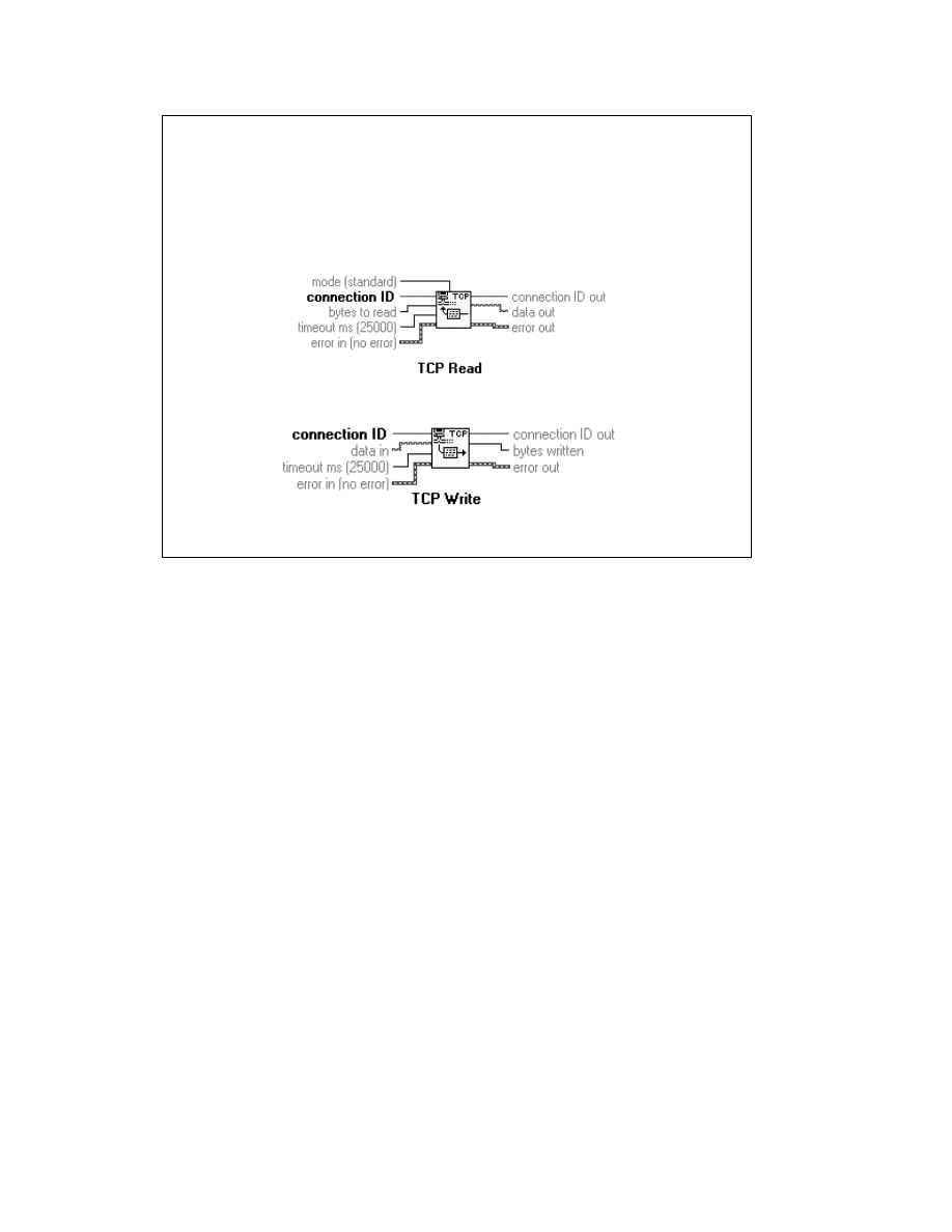
LabVIEW Advanced 1 Course Manual
131
© National Instruments Corporation
TCP Read Function
The TCP Read function receives up to the number of bytes specified by bytes to read from the
specified TCP connection ID and returns the results in data out. If the operation is not
complete in the specified timeout period, the function completes and returns an error. error in
and error out clusters describe any error conditions. The mode input specifies the behavior of
the read operation for the four different options: Standard, Buffered, CRLF, and Immediate.
These are described below:
Standard: If you use the standard mode, the function returns the number of bytes received so
far. If less than the requested number of bytes arrive, it reports a timeout error.
Buffered: If you use the buffered mode, the function returns the number of bytes requested or
none. If less than the requested number of bytes arrive, it reports a timeout error.
CRLF: If you use the CRLF mode, the function returns the bytes read up to and including the
CR (carriage return) and LF (line feed) or nothing. If a CR or LF are not found, it reports a
timeout error.
Immediate: If you use the Immediate mode, the function will wait until any bytes are received.
This function will wait the full timeout if no bytes have been received.
LV Adv I 131
The TCP/IP Functions
TCP Read Function
TCP Write Function

LabVIEW Advanced 1 Course Manual
132
© National Instruments Corporation
TCP Write Function
The TCP Write function writes the string data in to the specified TCP
connection ID. If the operation is not complete in the specified timeout
period, the function returns an error. bytes written identifies the number of
bytes transferred. error in and error out clusters describe any error
conditions.
Notice that all the data written or read is in a string data type. The TCP/IP
protocol does not state the type or format of the data transferred, so a string
type is the most flexible method. You can use the type cast and flatten to string
functions to send binary or complicated data types.
However, the receiver of this information must be informed of the exact type
and representation of the data to reconstruct the original information. Also,
when you use the TCP Read function, you must specify the number of bytes
to read. A common method of handling this is to send a 32-bit integer first to
specify the length of the data string that follows. The TCP Examples provided
with LabVIEW and the exercises in this lesson will provide more information
on these topics and on how the data typically is formatted for TCP/IP
communications.
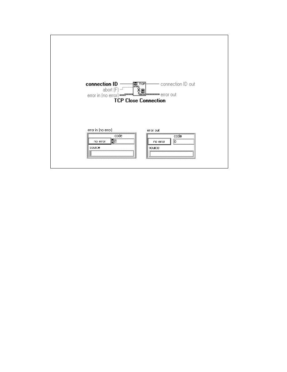
LabVIEW Advanced 1 Course Manual
133
© National Instruments Corporation
TCP Close Connection Function
The TCP Close Connection function closes the connection associated with connection ID. abort
determines whether LabVIEW closes the connection normally or aborts the connection. error in and
error out clusters describe any error conditions.
The TCP Close Connection function closes the connection to the remote application. Note that if there
is unread data and the connection closes, the unread data may be lost. This behavior is dependent on
your operating system. For example, the Sun operating system implementation will keep unread data
even after the remote application closes the connection. However, Windows NT immediately will delete
any unread data when a close connection is received. Connected parties should use a higher level
protocol to determine when to close the connection. Once a connection is closed, you may not read or
write from it again.
TCP Errors
The TCP functions and VI report errors in clusters in the same manner as the VIs for file I/O, data
acquisition, GPIB, and VISA, as shown below.
The error cluster contains the following:
•
status: a Boolean that has a value of TRUE if an error occurred
•
code: a numeric that is the error code returned
•
source: a string that gives one of the following:
- the name of the TCP function or VI where the error occurred followed by the error message, or
- the name of the last TCP function or VI to execute followed by the no error message.
If a TCP function or VI receives an error cluster with a TRUE status flag, the function passes the error
cluster out without changing it or attempting any TCP commands. If you do not wire error in, it
defaults to
no error
.
LV Adv I 133
The TCP/IP Functions
TCP Close Connection
TCP Errors

LabVIEW Advanced 1 Course Manual
134
© National Instruments Corporation
LV Adv I 134
Exercise 1-2
Students will examine a TCP Client VI
and TCP Server VI.
Time to complete: 10 min.

LabVIEW Advanced 1 Course Manual
135
© National Instruments Corporation
LV Adv I 135
Exercise 1-3
Students will build TCP client and server VIs
that pass information back and forth.
Time to complete: 20 min.
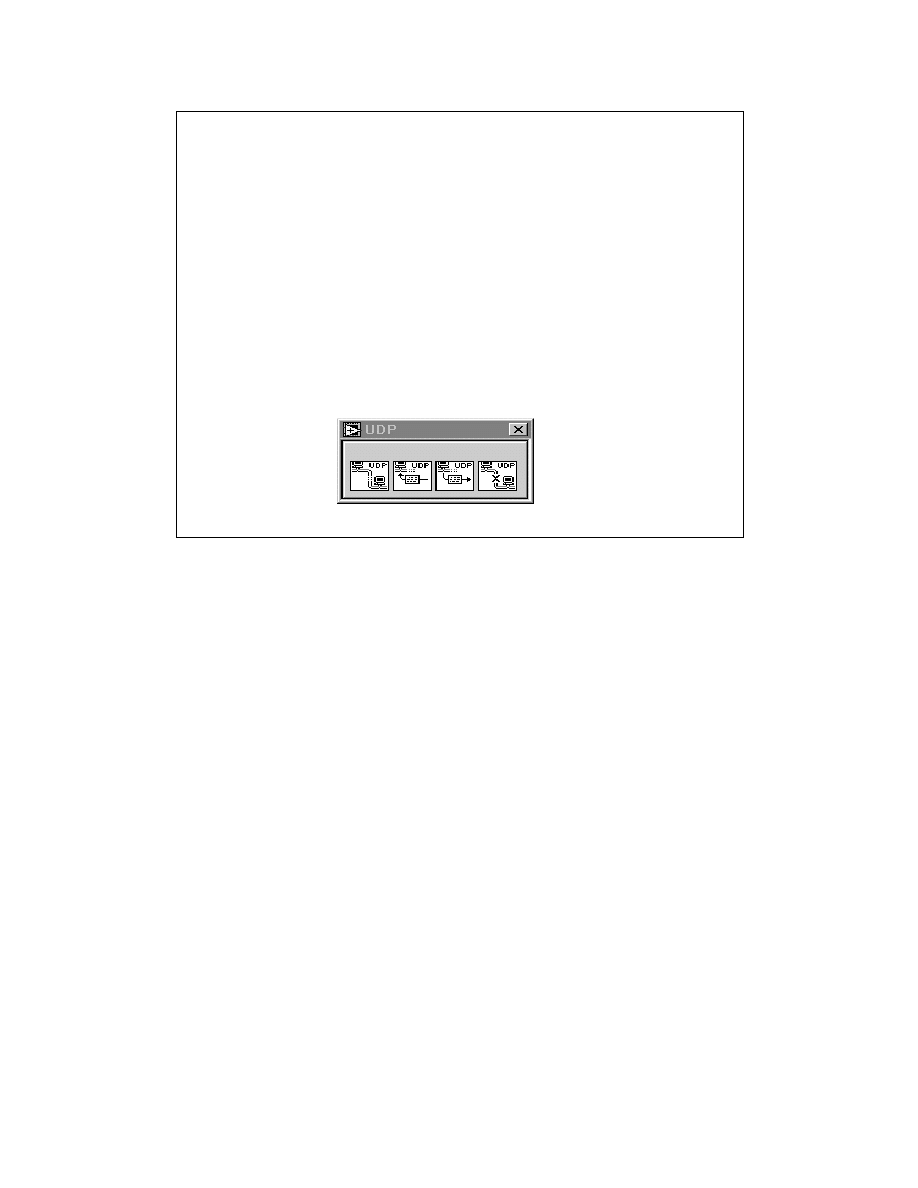
LabVIEW Advanced 1 Course Manual
136
© National Instruments Corporation
Another protocol that sits on top of IP is the User Datagram Protocol (UDP). You can use UDP
when you do not need all the power of TCP. Consider different methods of sending a package to
a friend. TCP is like using an overnight courier service to send the package, while UDP is like
mailing the package through the regular postal service. TCP has special tracking information
that assures that all data is sent and in the correct order, while UDP just sends the information as
is. UDP does not have as much overhead, does not perform data tracking, and uses shorter
header than TCP. UDP can communicate to specific processes on a computer. When a process
opens a network connection to a particular port, it receives only datagrams that are addressed to
that port on that computer. When a process sends a datagram, it must specify the computer
through its IP address and port as the destination. UDP is not a connection-based protocol like
TCP. This means that a connection does not need to be established with a destination before
sending or receiving data. Instead, the destination for the data is specified when each datagram is
sent. The system does not report transmission errors.There are several reasons why UDP is
rarely used directly. UDP does not guarantee data delivery. Each datagram is routed separately,
so datagrams may arrive out of order, or may be delivered more than once or not at all.
Typically, UDP is used in applications where reliability is not critical. For example, an
application might transmit informative data to a destination frequently enough that a few lost
segments of data are not problematic.
LV Adv I 136
User Datagram Protocol(UDP)
• UDP does not have as much overhead, does not
perform data tracking, and uses shorter headers
than TCP.
• UDP communicates with specific processes; it is not
connection based like TCP.
• Data delivery is not guaranteed.
• The LabVIEW UDP VIs are located in the Functions »
Communication » UDP subpalette.
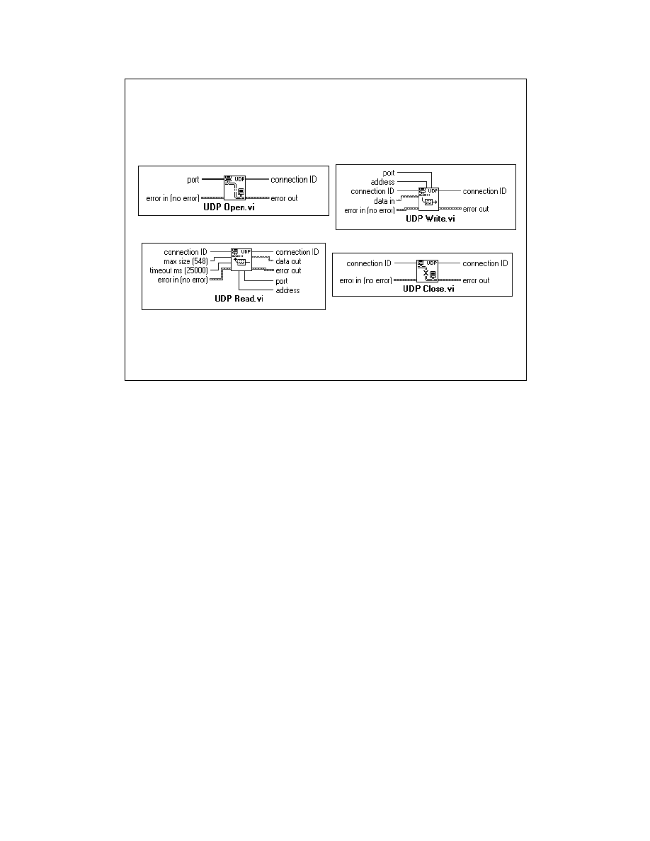
LabVIEW Advanced 1 Course Manual
137
© National Instruments Corporation
You can use the UDP Open VI to create a connection. A port must be associated with a
connection when it is created, so that incoming data can be sent to the appropriate application.
The number of simultaneously open UDP connections depends on the system. Similar to the TCP
VIs, the UDP Open VI returns a Network Connection refnum, connection ID, which is used in
all subsequent operations pertaining to that connection.
You can use the UDP Write VI to send data to a destination and the UDP Read VI to read data.
Each write requires a destination address and port. Each read contains the source address and port.
Packet boundaries are preserved. That is, a single read never contains data sent in two separate
write operations. In theory, you should be able to send data packets of any size. If necessary, a
packet is disassembled into smaller pieces and sent on its way. At their destination, the pieces are
reassembled and the packet is presented to the requesting process. In practice, systems allocate
only a certain amount of memory to reassemble packets. A packet that cannot be reassembled is
thrown away. The largest size packet that can be sent without disassembly depends on the
network hardware.When LabVIEW finishes all communications, calling the UDP Close VI frees
system resources.
LV Adv I 137
User Datagram Protocol (UDP)

LabVIEW Advanced 1 Course Manual
138
© National Instruments Corporation
LV Adv I 138
Exercise 1-4
Students will use UDP to transfer data
between VIs on different computers.
Time to complete: 15 mins.

LabVIEW Advanced 1 Course Manual
139
© National Instruments Corporation
LV Adv I 139
Summary Lesson 1
•
TCP/IP and UDP are a set of communication
protocols, where IP(Internet Protocol) is the bottom
layer and TCP(Transmission Control Protocol) or UDP
(User Datagram Protocol) is the method of
communication between two computers.
•
TCP is usually the best choice for network
communications between applications, because it
makes sure that all data is delivered to its destination.
TCP and UDP also are the protocols supported by all
the different operating systems on which LabVIEW
runs.
•
Each computer on an IP network has a unique 32-bit
address called the IP address. You also must specify
a communication port number between 0 and 65535.
•
Make sure your computer has the correct hardware
and software installed for TCP/IP communications.

LabVIEW Advanced 1 Course Manual
140
© National Instruments Corporation
LV Adv I 140
Summary Lesson 1 cont.
•
The client and server models are commonly used for
networked communication.
•
A client application initiates the connection and
instructs the server to read and/or write data. A server
application waits for a connection and then reads or
writes data as instructed by the client.
•
The UDP VIs in LabVIEW are lower level than the TCP
VIs and used when you do not need all the features
of TCP.

LabVIEW Advanced 1 Course Manual
141
© National Instruments Corporation
Introduction
This lesson describes a mechanism for controlling LabVIEW VIs and
applications programmatically. It also allows you to control VIs and
applications remotely over a TCP/IP network. This powerful mechanism is
called the VI server.
LV Adv I 141
Lesson 2
VI Server
You Will Learn:
• About VI Server capabilities
• About application objects
• About virtual instrument objects
• About strictly typed and non-strictly
typed refnums
• About remote communication

LabVIEW Advanced 1 Course Manual
142
© National Instruments Corporation
The new concept of the VI server in G allows programmatic access to many of its features. This
provides a mechanism for controlling VIs and applications programmatically. In previous
versions of LabVIEW, you could control LabVIEW functionality mostly interactively. The VI
Control VIs were used in previous versions of LabVIEW to control certain features in
LabVIEW, such as when a VI is loaded into memory and when it is released. You could also
control other properties of a VI such as opening, closing, and resizing panels, etc. These VIs
were name based and not available outside of LabVIEW. The new VI server functionality is
refnum based. This new interface provides a powerful but simple mechanism for controlling the
properties of LabVIEW VIs and LabVIEW itself, as well as invoking methods on them. This
extends the flexibility of the language. Now, the VI Server can be controlled programmatically
from LabVIEW, as well as externally from a client application.
LV Adv I 142
Introduction
Provides programmatic access to LabVIEW
objects and functionality
• LabVIEW application and LabVIEW VIs
• Previously only available interactively, via
dialogs, menu items, etc.
Supercedes VI Control VIs
• Were name based, not available from outside
of LV
• Now is refNum based, has external interfaces
What is a VI Server?

LabVIEW Advanced 1 Course Manual
143
© National Instruments Corporation
LV Adv I 143
Using the VI Server
• Dynamically load VIs
• Programmatically control a VI’s user interface
• Create server and client applications
• Create plug-in architecture
Some tasks using the LabVIEW VI Server
You can use the VI Server capabilities to accomplish various enhancements to your
applications. Some tasks you can implement are described below.
You can load VIs into memory dynamically, rather than having them statically linked into your
application, and call them just like a normal subVI call using VI server functions. This can be
useful if you have a large application and want to save memory or startup time.
You can also control aspects of the user interface of a VI programmatically. For example, you
might want to determine the location of a VI window dynamically, or scroll a panel so that a
particular part of the panel is visible, or close or open the panel window. All these properties of
a VI front panel can be controlled programmatically through the VI Server.
You can easily create a server application that exports functions that can be called from
LabVIEW on the Internet.
You can change properties of a VI programmatically and save those changes to disk. For
example, during development of your application, you might want VIs configured so that
debugging is available, run-time pop-up menus are available, scroll bars are visible, and
windows are resizable. However, when you distribute your application, you may want to turn
off these features, as well as ensure that certain other properties are correctly set, such as
whether a VI is reentrant, what execution system the VI is set to run within, and the path to the
help file of a VI. All these properties can be programmatically set and queried via the VI Server,
enabling you to write applications that edit VIs, rather than going through the VI Setup dialog
box for each and every VI.

LabVIEW Advanced 1 Course Manual
144
© National Instruments Corporation
You can create a plug-in architecture for your application to add functionality to your
application after it is distributed to customers. For example, you might have a set of data
filtering VIs, all of which take the same parameters. By designing your application to
dynamically load these filters from a plug-in directory, you can ship your application with a
partial set of these filters and make more filtering options available to users by simply placing
the new filtering VIs in the plug-in directory.

LabVIEW Advanced 1 Course Manual
145
© National Instruments Corporation
Object-oriented programming is based on objects. An object is a self-contained software
component. Some examples of objects are windows, buttons, files, etc. An object is defined in
terms of the data it contains and the functions it provides for using and manipulating this data.
Most object-oriented programming languages support a class-based approach to develop
objects. A class defines the type of data contained in an object and the methods and properties to
be used to manipulate the data.
LV Adv I 145
Glossary of Terms
Object-Oriented Terminology
• Objects are self-contained software components.
• Class defines the type of data contained in the
object.
• Methods are functions that can be performed on
the object.
• Properties are functions that manipulate the state
of an object.

LabVIEW Advanced 1 Course Manual
146
© National Instruments Corporation
An object in this case is the Person object. The data stored by the object is all the attributes of
the object, such as name, address, etc. The functions that can be performed on the object are its
methods and properties. In the case of the Person object, they are get_name, set_name,
get_address, set_address, etc.
LV Adv I 146
Objects
Example of an Object
Person Object
Data
name: Mark Doe
address: 102, West Street,
etc...
Methods & Properties
get_name()
set_name()
get_Address()
set_address()
etc...
LabVIEW Advanced 1 Course Manual
147
© National Instruments Corporation
The LabVIEW VI Server is made up of a core set of services. These services are accessible
through the different clients as show in the figure on the slide above. The different client
interfaces like ActiveX Automation client, TCP/IP client, and G language functions allow
access to the LabVIEW VI Server.
Diagram Access: LabVIEW diagram functions enable you to control the VI server from any
platform to another.
Network Access: An instance of LabVIEW can be controlled from another LabVIEW across
the network using TCP/IP.
ActiveX Interface: Automation clients like a Visual Basic script or a Visual C++ program can
control the VI server.
You can program the VI server through either LabVIEW diagram functions or an ActiveX
client. In this lesson, you will study the diagram and network access functions. The ActiveX
interface is discussed in later lessons in this module.
LV Adv I 147
VI Server Clients
VI Server
ActiveX Interface
Diagram Functions
TCP/IP
ActiveX Automation
Client
TCP/IP
Client
LabVIEW Advanced 1 Course Manual
148
© National Instruments Corporation
The VI Server functionality is exposed through references to two main classes of objects: the
Application object and the VI object. Each of these classes exposes the operations on the object
through methods and properties.
An application class reference refers to a local or remote LabVIEW environment (object). The
properties and methods of the LabVIEW application object can, for example, change LabVIEW
preferences and return system information.
A virtual instrument class reference refers to a specific VI in LabVIEW. The properties and
methods of the VI object can, for example, change the VI’s execution and window options. The
LabVIEW diagram functions for manipulating these properties and methods are discussed next.
LV Adv I 148
VI Server Capabilities
•
Two classes of objects
- Application
—
just one per G/LabVIEW application
- Virtual Instruments
• Each class offers:
- Properties
—
single valued attributes of the object:
read/write, read only, write only
- Methods - functions that operate on the object
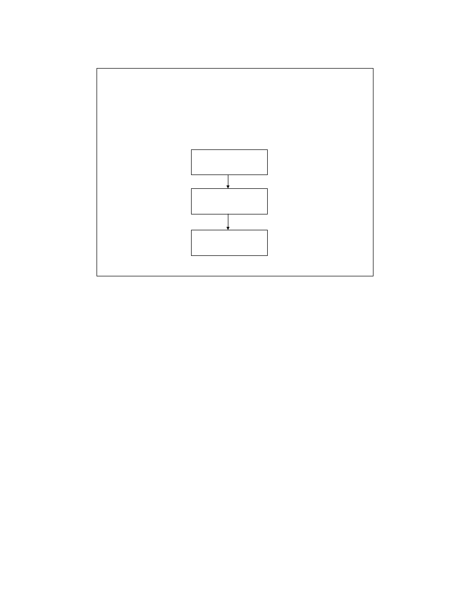
LabVIEW Advanced 1 Course Manual
149
© National Instruments Corporation
.The VI server programming model follows the convention similar to File I/O and network
references. First, you create a reference to either the Application object or the VI object. When
you create a reference to an object, it holds on to an object. You can pass the reference to a
function that operates on the object. When you are finished with it, you close the reference as
shown in the flowchart in the slide above. When you close a reference, you release the object.
In the next two slides, we will discuss the various LabVIEW functions to reference the
Application and Virtual Instrument objects.
LV Adv I 149
Programming Model
- Follows file I/O, VISA model
Open Reference
Invoke Methods
Get/Set Properties
Close Reference
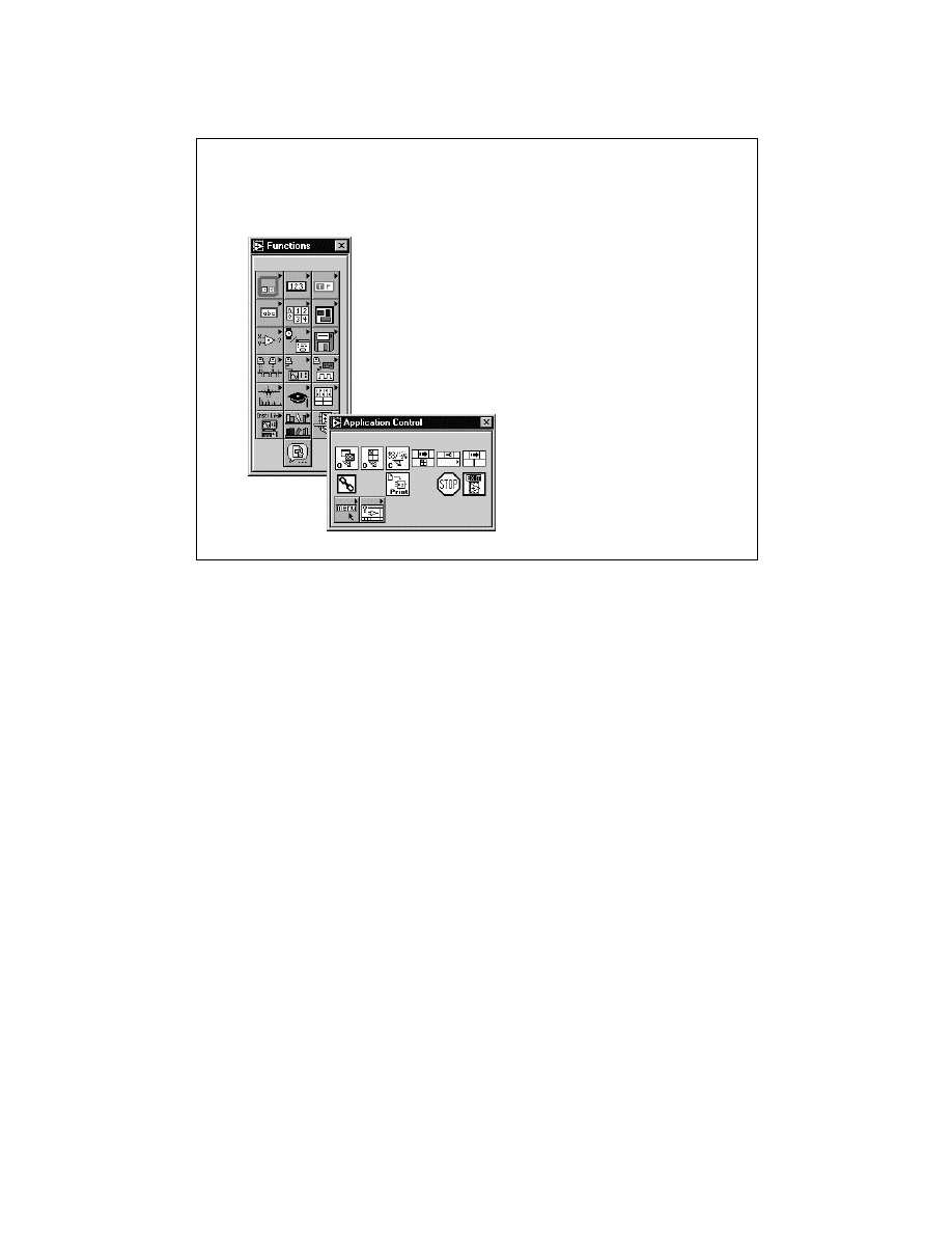
LabVIEW Advanced 1 Course Manual
150
© National Instruments Corporation
.You can access all the VI Server related functions by choosing Functions » Application
Control.
LV Adv I 150
VI Server Functions
All VI Server functions accessed
by selecting
Functions »
Application Control
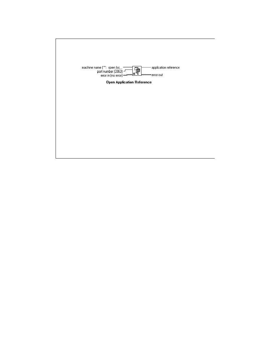
LabVIEW Advanced 1 Course Manual
151
© National Instruments Corporation
LV Adv I 151
Application Object - Opening
If machine name is
•
Unwired or empty string
– A “local” reference to the LabVIEW application is
generated
•
Otherwise, an IP address to a LabVIEW server
– Upon completion: a TCP connection has been
established and LabVIEW servers are ready to talk
– A “remote” reference is generated
Port number
• Allows multiple servers on a single machine
Open Application Reference
When you open a reference to the Application object using the Open Application Reference
function, the reference is either to the current LabVIEW or a LabVIEW across the network. If
the machine name is left unwired or empty, the function creates a reference to the current
application. Otherwise, the machine name is treated as a TCP/IP address and can be in dotted
notation or domain name notation.
The port number input allows you to specify multiple servers on a single machine.
You can use the application reference output as an input to the Property and Invoke nodes to
get or set properties and invoke methods on the application. You can also use the application
reference as the input to the Open VI Reference function to get references to VIs in that
application.
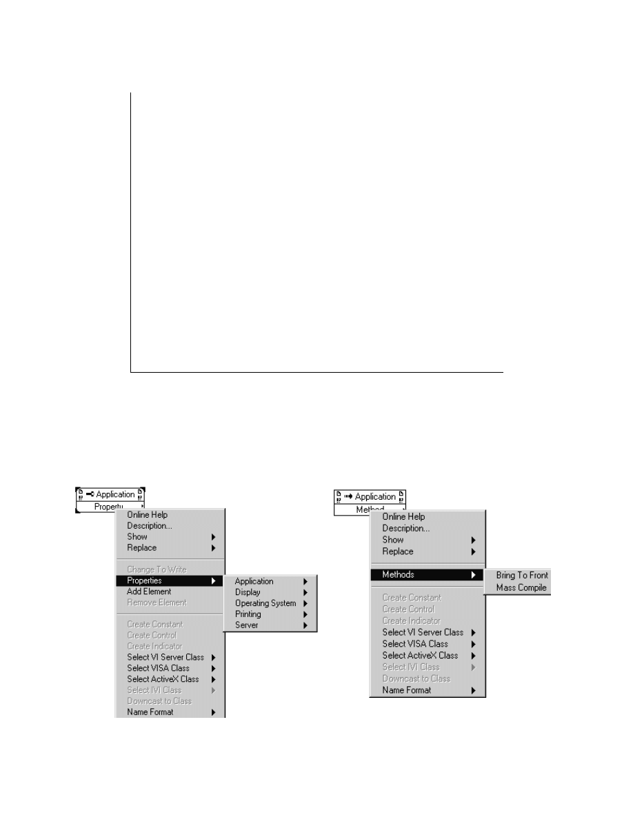
LabVIEW Advanced 1 Course Manual
152
© National Instruments Corporation
LV Adv I 152
Application Object - Operations
Properties: mostly read only
• Environment: OS name, version, CPU type
• Application name, version, directory
• VIs in memory
• Printing attributes: supports custom
printing
• All read/write
Methods
• Few currently exported
The operations that can be performed on the Application object are through its properties and methods.
For operations on a remote object, the VI server takes care of sending the information across the network
and sending the results back. Your program looks virtually identical, regardless of whether the operation
is remote or local. However, for remote (or external) clients, information is filtered for security.
The properties and methods of the Application object are shown below.
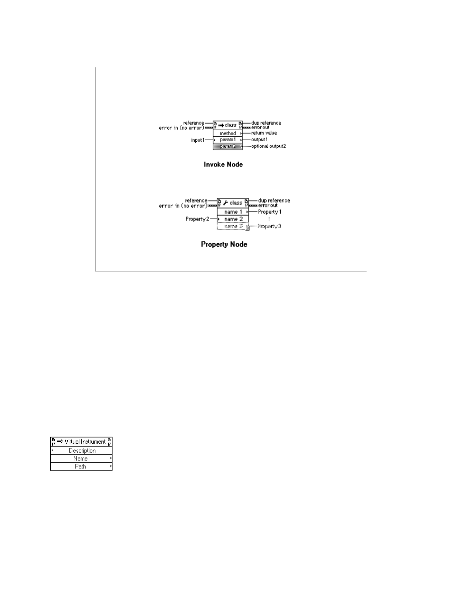
LabVIEW Advanced 1 Course Manual
153
© National Instruments Corporation
LV Adv I 153
Using Functions
Invoke Node and Property Node
Many of the operations on Application and VI objects are available through the Property and
Invoke node functions. Both of these nodes have two inputs and two outputs at the top of the
node, and a variable list of inputs and outputs below that.
Reference is an Application or VI reference, and dup reference is a copy of the reference used
to pass the value to other functions.
When you wire an Application or VI refnum to the reference input, the node automatically
adapts to that data type and makes available only those operations applicable to that type.
You can use the Property node to get and set properties of an application or a VI. You can get
or set multiple properties using a single node, as shown below. VI Description, VI Name, and
VI Path properties have been selected on a single node. You choose to read or write properties
by selecting Change to Read or Change to write in the pop-up menu.
LabVIEW Advanced 1 Course Manual
154
© National Instruments Corporation
The property node executes from the top to the bottom. If an error occurs midway down the
node, the remaining properties are ignored and an error is returned.
You can use the Invoke Node to perform actions, or methods, on an application or a VI. A
single node can execute only one single method on an application or VI.
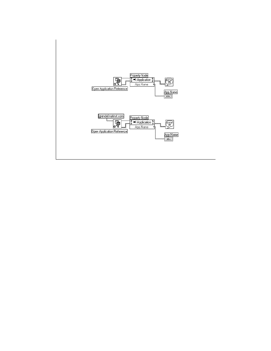
LabVIEW Advanced 1 Course Manual
155
© National Instruments Corporation
LV Adv I 155
Example of Accessing an
Application Property
Open a local reference
Open a remote reference
Before accessing properties or methods of the application, you must create an application
reference by executing the Open Application Reference function. The examples on the slide
above demonstrate how you can access the filename of the application executable on a local
machine and a remote machine.
The first example shows that a local reference is opened and the name of the application is
displayed in App.Name. The second example demonstrates the same functionality over the
network. A remote reference is opened to the server
grendel.natinst.com
, and then the
name of the remote application is displayed.
Next, we will discuss the VI object functions.
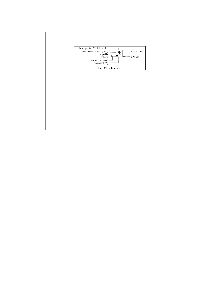
LabVIEW Advanced 1 Course Manual
156
© National Instruments Corporation
LV Adv I 156
1
VI Object Functions
Open VI Reference
•
vi path: by path: loads VI into memory (if
necessary)
• Will use VI of same name if already in memory
• Relative path: relative to directory of caller
•
vi path: by name (string): VI must already be in
memory
•
application reference (optional input)
• Specifies the LV where the VI resides
• If remote, specifies the remote LV where the VI
resides
The Open VI Reference function returns a reference to a VI specified by a name string or path
to the VI’s location on disk.
VI path control or name is polymorphic and can accept a string containing the name of the
desired VI, or a path containing the complete path (including the name) to the desired VI. If you
wire a name string, the VI must already be in memory. If you wire a path and the VI is already
in memory, you get the one in memory, whether its path is the same as the input or not.
application reference is a reference to a LabVIEW application to which the specified VI
belongs. It is obtained from the Open Application Reference function. This input is optional. If
you do not wire anything to the application reference, it will assume that you would like to refer
to the local application.

LabVIEW Advanced 1 Course Manual
157
© National Instruments Corporation
LV Adv I 157
VI Object Functions
Open VI Reference (cont.)
•
Options: bitset of flag
• Advanced feature
• 0x1: record modifications
• 0x2: open templates for editing
•
Password:
• If valid, allows editing of VI via this reference
The Options input to the Open VI reference function is an advanced feature. It may be a
combination of the following values: 0x01: Record Modifications
0x02: Open Templates for Editing
If Options is set to 0x01, it starts recording modifications and if it is set to 0x02, it acts as if the
File » Edit Template menu item is selected.
The password input is needed when you would like to modify password protected VI through
the VI reference. If the VI is password protected and you enter an incorrect password, the
function returns an error and an invalid VI reference. If you provide no password when opening
a reference to a VI that is password protected, you can still get the reference, but you can
perform only operations that do not edit the VI. If the VI is not password protected, this input is
ignored.
We will discuss the type specifier input later in this lesson.

LabVIEW Advanced 1 Course Manual
158
© National Instruments Corporation
LV Adv I 158
VI Object - Operations
Many of the functions “edit” the VI
• Require that the VI be in an editable state
To be editable, a VI can not be
• Active (running as a top level VI)
• Reserved for running - some caller is
active
• Locked
• Password protected
The operations that can be performed on a VI object are through its properties and methods (that
is, through the Property and Invoke nodes). Most of these functions edit the specified VI.
If you intend to perform editing operations on a VI, the VI should be in an editable state.
For a password protected VI, you must provide the password to the password string input of the
Open VI Reference function. Also, a VI that needs to be edited should not be executing or
reserved for execution. Any time you have a strictly-typed reference to a VI, your VI is reserved
for running. This reference must be closed before you can invoke editing methods or editing
properties.
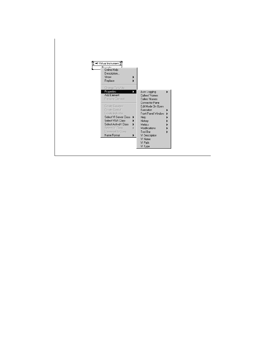
LabVIEW Advanced 1 Course Manual
159
© National Instruments Corporation
LV Adv I 159
VI Object - Properties
You can access the Property Node function from the Functions » Application Control
menu. Once you wire the VI reference to the Property Node, you can access all the VI
class properties. The properties of the VI object are shown in the slide above.
Many of the properties of the VI that are exposed correspond to the properties available
in the VI Setup… dialog box. Most of the properties are read and write. Properties such
as name, path, type, metrics, etc. are read-only. Some properties are transient (for
example, window position, title, etc.).
Once you select a property, you can get help information about it by popping up and
selecting “Help for Property Name”.
In the next slide, you shall examine a simple VI that demonstrates how to access a
property of a specific VI.
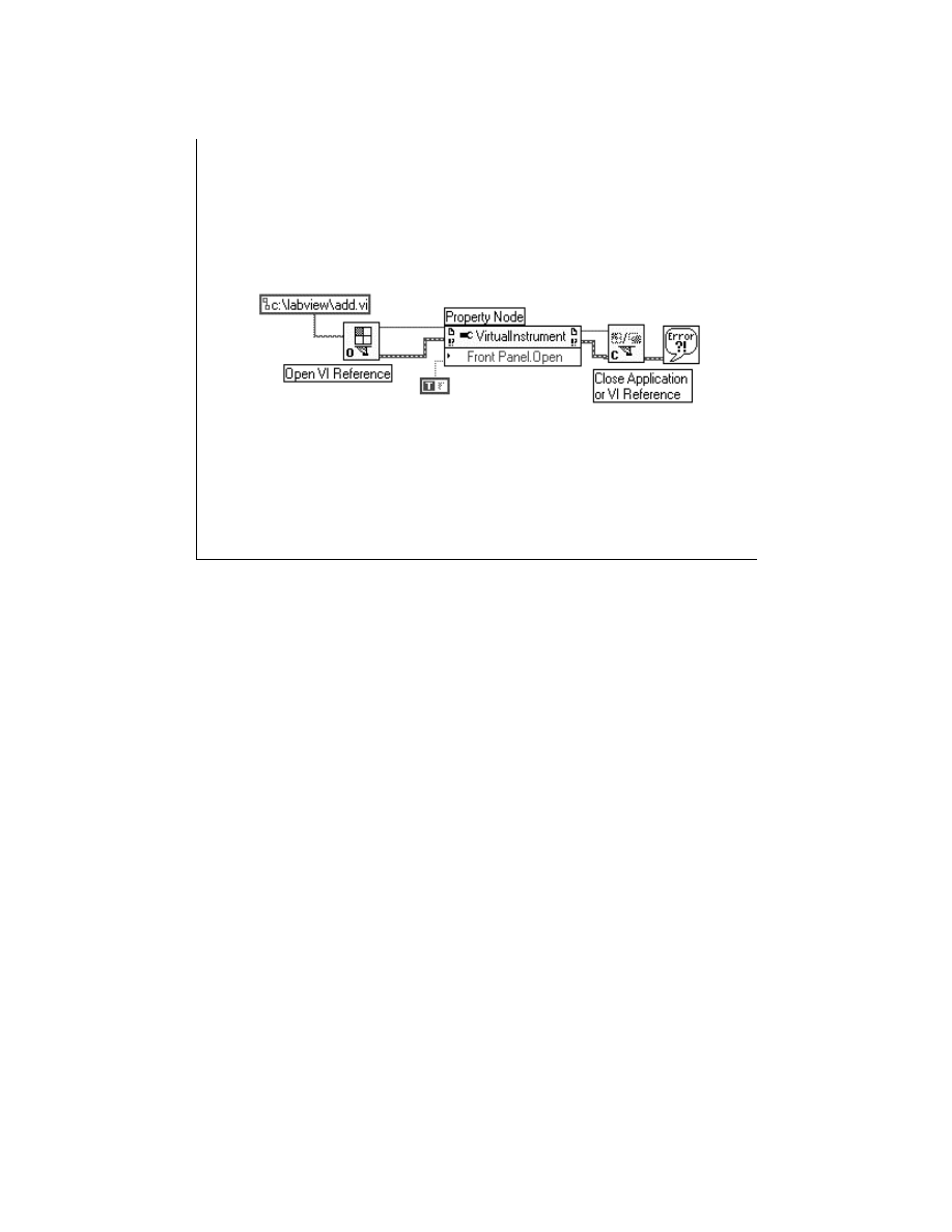
LabVIEW Advanced 1 Course Manual
160
© National Instruments Corporation
LV Adv I 160
VI Object - Properties- Example
The above example shows how to access a property of class Virtual Instrument.
This VI opens a reference to the specified VI (add.vi), and opens its front panel.
Wiring a TRUE to its Front Panel.Open property opens the front panel of the VI.
Note: In this example, the Open Application Reference function is not required to
generate a reference to a local version of LabVIEW, because the Open VI
Reference function assumes local application if nothing is wired to its reference
input.
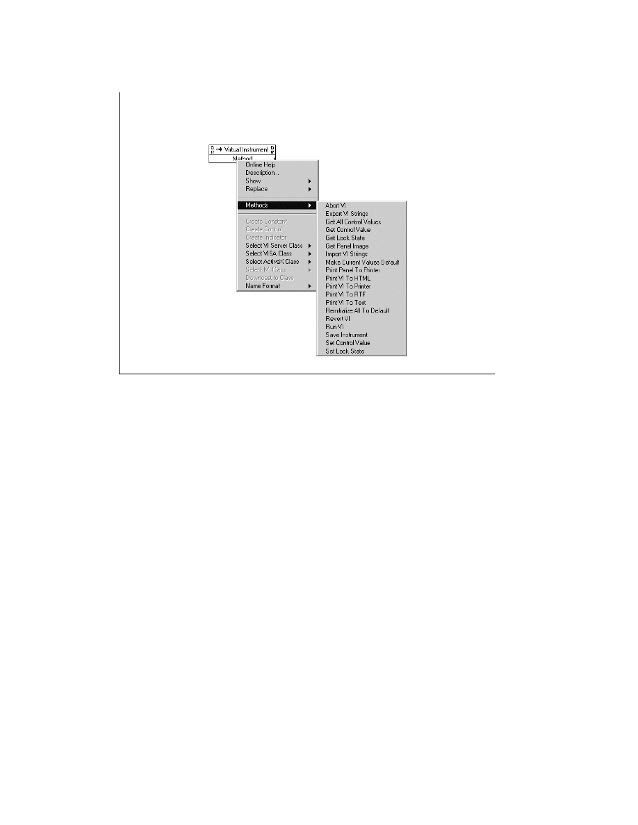
LabVIEW Advanced 1 Course Manual
161
© National Instruments Corporation
LV Adv I 161
VI Object - Methods
When you wire the VI reference to the Invoke Node function, you can access all the VI
class methods.
Some of the important methods exported by the VI Server are Export VI strings, Set Lock
State, Run VI, Save Instrument, etc. The Export VI Strings method exports strings
pertaining to VI and front panel objects to a tagged text file. The Set Lock State method
sets the lock state of a VI. The Run VI method starts VI execution. The Save Instrument
method saves a VI.
Once you select a method, you can get help information about it by popping up and
selecting “Help for Method Name.”
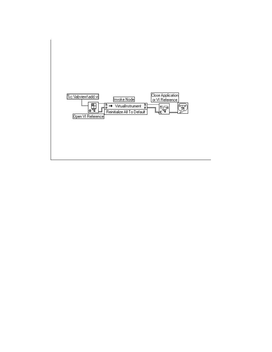
LabVIEW Advanced 1 Course Manual
162
© National Instruments Corporation
LV Adv I 162
VI Object - Methods - Example
The above example uses the Reinitialize All To Default method to change the
current values of all controls on the front panel of add.vi to their defaults. First, the VI
opens a reference to add.vi, which belongs to the local version of LabVIEW. This VI
Reference is used to access the Reinitialize All To Default method.
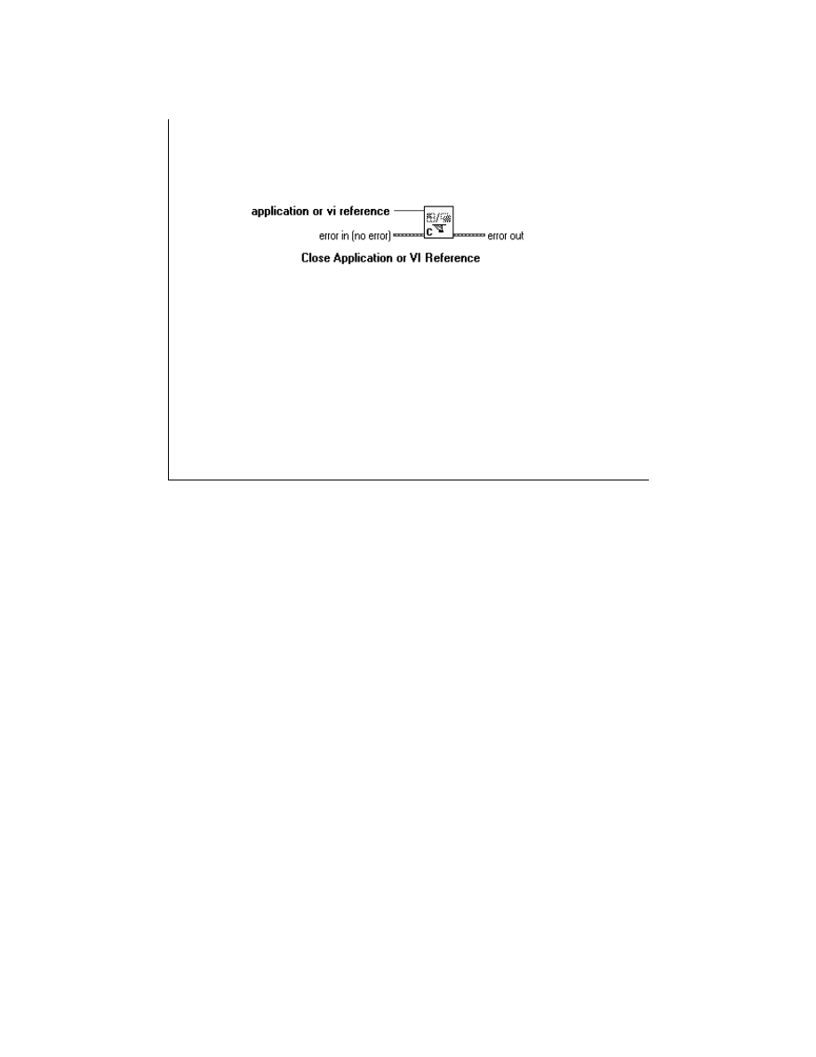
LabVIEW Advanced 1 Course Manual
163
© National Instruments Corporation
LV Adv I 163
VI Object - Closing Function
Close Application or VI Reference
•
Used for both application references and
VI references
•
VI may be unloaded from memory
•
Does NOT prompt to save changes!
The Close Application or VI Reference function releases the application or VI
reference. If you close a reference to a specified VI, and there are no other references to
that VI, the VI maybe unloaded from memory.
This function does not prompt you to save changes to the VI. By design, VI Server
actions should avoid causing user interaction. You must use the Save Instrument
method to save the VI programmatically.
Note: If you do not close the application or VI reference with this function, the
reference closes automatically when the top-level VI associated with this function
finishes execution. However, it is a good programming practice to conserve the
resources involved in maintaining the connection by closing the reference when you
finish using it.

LabVIEW Advanced 1 Course Manual
164
© National Instruments Corporation
LV Adv I 164
Exercise 2-1
Students will build and run a VI to call another VI
programmatically through the VI Server Interface.
Time to complete: 10 min.

LabVIEW Advanced 1 Course Manual
165
© National Instruments Corporation
LV Adv I 165
Exercise 2-2
Students will complete and run a VI to set/reset
properties of another VI through the VI Server Interface.
Time to complete: 10 min.

LabVIEW Advanced 1 Course Manual
166
© National Instruments Corporation
LV Adv I 166
Strictly-Typed VI Refnums
• A data type that encodes the connector pane type
information or (LV calling conventions)
- Open VI Reference function
Uses only type info at edit/compile/run time;
value is ignored at run time
- Call By Reference
Uses type info at edit/compile time to
determine the VI to call
A strictly-typed VI refnum is a data type that contains the connector pane information
of a VI.
Applications of strictly-typed refnums
Strictly-typed refnums are used in applications where you need to call a VI
dynamically. In these applications, there are two different situations in which they are
used. The first situation is when you want to pass a strictly-typed VI reference into a
subVI as a parameter. To implement this, connect the strictly-typed VI refnum control
to the connector pane of the VI and wire the refnum terminal to the input of a Call By
Reference node. The value of the refnum is used to determine the VI to call.
In the second situation, you can determine whether the VI that is opened has the same
connector pane as that of the strictly-typed VI. For this, you can use a strictly-typed
refnum control as the type specifier for the Open VI Reference function. This function
ignores the value of the control. Only the type information is used by the Open VI
Reference function to check whether the VI that is opened has the same connector
pane as that of the strictly-typed VI refnum. This type specifier determines the type of
the Open VI Reference’s output VI reference, and this type information flows wherever
that wire goes.
We will discuss the Call By Reference Node later in this lesson.
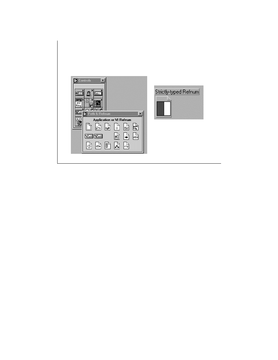
LabVIEW Advanced 1 Course Manual
167
© National Instruments Corporation
LV Adv I 167
Creating a Strictly-typed
Refnum
• Pop-up
• Drag and drop
To create a strictly-typed refnum, select Controls » Path&Refnum » Application or
VI Refnum from the front panel of a new VI. Pop up on the refnum and choose Select
VI Server Class » Browse…. Next, the Choose VI to open dialog box will appear and
prompt you for a VI. Choose a VI. The refnum stores the connector pane information
of the VI (takes a snapshot of the connector pane of the VI). Its connector pane is
displayed in the type specifier. This means that you are opening a reference to a VI
that has a connector pane of the type you have just chosen. It does not store any link to
the VI you select.
You can also create a strictly-typed refnum by using Drag and Drop. Wherever you
find a VI icon, you can drag it on to the refnum.

LabVIEW Advanced 1 Course Manual
168
© National Instruments Corporation
LV Adv I 168
Configuring a Strictly-typed
Refnum
• Configure the data type of the refnum
control
• The value of the refnum control is
determined at run time
• from the Open VI Reference function
Note: Configuring a strictly-typed refnum does not open
a reference to the selected VI.
Once you configure a strictly-typed refnum, you establish its type (or connector
pane). There is no permanent association between the reference and the selected VI.
It does not open a reference to a specific VI. You must still use the Open VI
Reference function to obtain a valid VI Reference. The value of the strictly-typed
reference is determined at run time by the Open VI Reference function.
After you select connector panes for strictly-typed refnums, the connector pane is
retained in the VI refnum. Select VI Server Class » Strictly-typed VIs. If you exit
LabVIEW, these connector pane selections are not retained the next time you launch
the application.
Note: Establishing a refnum’s type does not give you a reference to a selected VI.
You will need to use the Open VI Reference function to get a reference to a
selected VI.

LabVIEW Advanced 1 Course Manual
169
© National Instruments Corporation
LV Adv I 169
Advantages of Strictly-Typed
Refnums
• Moves type checking up front
- Happens in Open VI Reference at run time
• Allows strong typing at Call By Reference
Node
- At edit time, NOT run time
• Strong typing means…
- No interpretation or type checking at call
•
Result: VERY FAST CALL!
Strictly-typed VI Refnums are used while dynamically calling a VI. They have an
advantage of speed over the virtual instrument references. A strictly typed reference
makes passing data easier and faster. Because all type checking is done at edit time, the
call to the VI is very fast. For a virtual instrument class reference, passing data is more
difficult because you must flatten and unflatten the data.

LabVIEW Advanced 1 Course Manual
170
© National Instruments Corporation
LV Adv I 170
Behavior of Strictly-Typed VI
Refnums
• When a refnum is opened, the
referenced VI is reserved for running.
• Makes it non-editable
• Opening a strictly-typed VI refnum may
cause a recompile
• Can happen only at root loop
When a strictly-typed refnum is opened, the referenced VI is reserved for running. Hence the
VI becomes noneditable.
For example, you can open a VI Reference to a target VI and edit the VI. While this reference
is still open, you can open another reference (for example, a strictly-typed reference) and call
the target VI as a subVI through the Call By Reference node. However, while the strictly-
typed reference is active (that is, until the reference is closed), editing operations through the
Property and Invoke nodes will fail because the VI to which they refer is reserved for running
by the strictly-typed reference.
Because opening a strictly-typed VI refnum puts it in the “reserved for running” state, it
means that the VI has been checked to make sure it is not bad, that it is not currently running
as a top level VI, and that it has been compiled (if necessary), as well as a few other checks. A
VI referenced by a strictly-typed VI Reference can be called using the Call By Reference
node at any moment without having to check all these conditions again. Thus, in this state you
cannot edit the VI or do anything to it that would change the way it would execute.
The next exercise will demonstrate the difference between a strictly-typed VI reference and a
virtual instrument reference.

LabVIEW Advanced 1 Course Manual
171
© National Instruments Corporation
LV Adv I 171
Exercise 2-3
Students will complete and run a VI that
demonstrates the difference between strictly typed
and plain refnums.
Time to complete: 10 min.
LabVIEW Advanced 1 Course Manual
172
© National Instruments Corporation
LV Adv I 172
Remote Communication
LabVIEW Running
on local machine controls
the LV on remote machine
programmatically
LabVIEW Running
on Remote machine
Called VIs must exist
TCP/IP
LabVIEW allows most VI Server operations in a remote version of LabVIEW across a
TCP/IP network. You can easily create a server application that exports functions that can
be called over the network from LabVIEW. For example, you may have a data acquisition
application that acquires and logs data at a remote site and you may want to sample that
data occasionally from your local machine. Through a simple preference setting, you can
make some VIs callable from across the Internet so that transferring the latest data is as
easy as a subVI call. The VI Server handles all the networking details and makes it work,
no matter what platform the client or the server are running on.
You will use the very same functions and references to access objects on remote machines.
An important aspect of both the Application and VI references is their network
transparency. Thus, you may open references to remote objects the same way you open
references to those objects on your local machines. For operations on remote objects, the
VI Server takes care of sending the information about the operation across the network and
sending results back. For all practical purposes, your program should look virtually
identical regardless of whether the operation is remote or local.
To open an application reference to a remote version of LabVIEW, you must specify the
machine name input to the Open Application Reference function. Then LabVIEW
attempts to establish a TCP connection with a remote VI Server on that machine on the
specified port.
For security purposes, to access the server, certain configurations must be set. In the next
two slides, we will discuss these configurations and protocols.
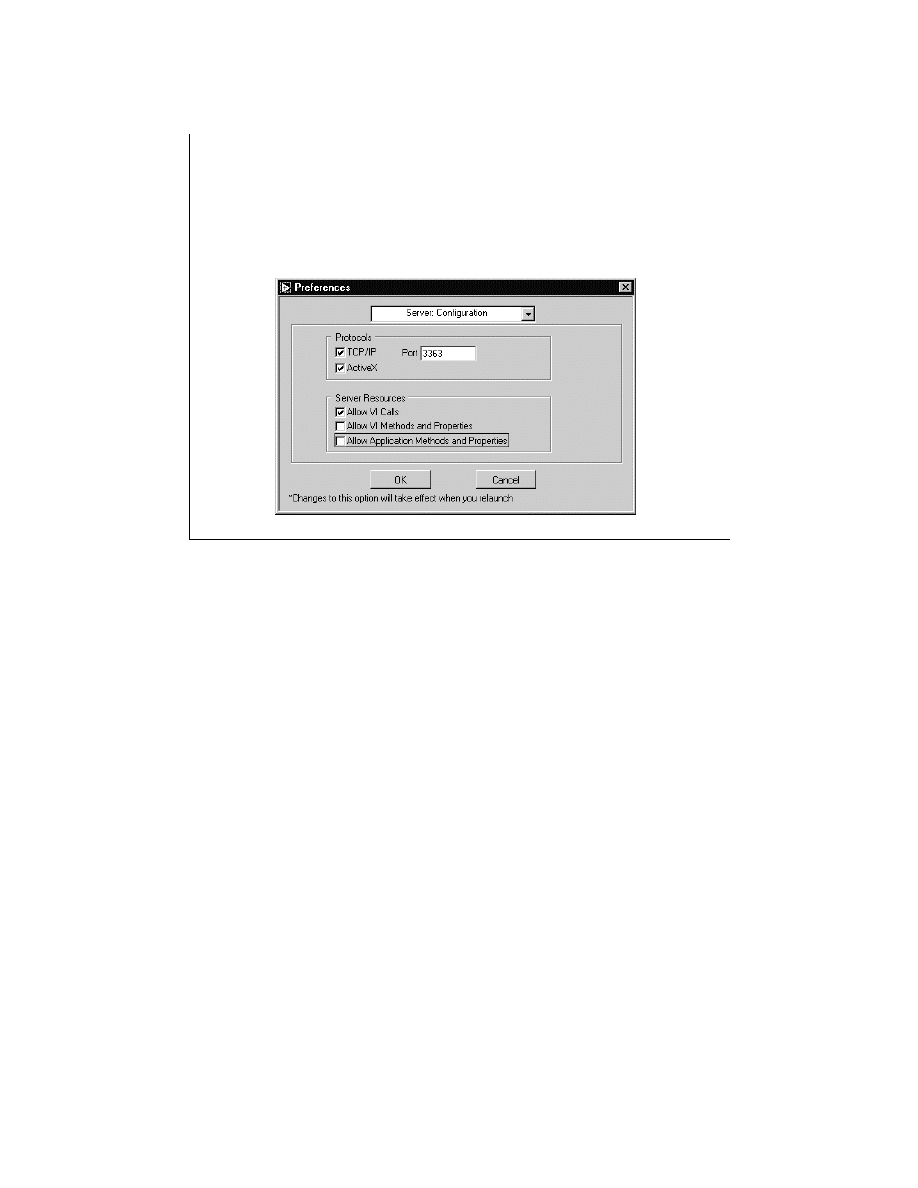
LabVIEW Advanced 1 Course Manual
173
© National Instruments Corporation
LV Adv I 173
Server Configuration
Select Edit » Preferences and then Server » Configuration
from the drop down menu.
To configure the VI Server for external applications, select Edit » Preferences on the server
machine and then select Server:Configuration from the drop-down menu. The screen shown
on the above slide appears.
The options shown on this screen specify through which communication protocols other
applications can access the VI Server: TCP/IP or ActiveX protocols. For a remote machine,
you must enable TCP/IP and you must enter a Port number that client applications can use
to connect to the server. We will discuss the VI Server ActiveX interface in later lessons in
this manual.
Once you have enabled TCP/IP, you should also configure which Internet hosts have access
to the server. We will discuss this in the next slides.
With Server:Configuration selected, you should also specify which server resources are
available to applications that access the VI Server. The server resources are discussed below:
VI Calls allow applications to make calls to VIs on the server. You can also configure which
VIs they have access to. This is discussed in the next slide.
VI Methods and Properties allows applications to read and set the properties of VIs on the
server.
Application Methods and Properties allows applications to read and set the properties of
the server.
In the slide above, TCP/IP server access has been enabled for port 3363. The server allows
remote clients to call VIs, but does not allow access to VI or application methods and
properties.
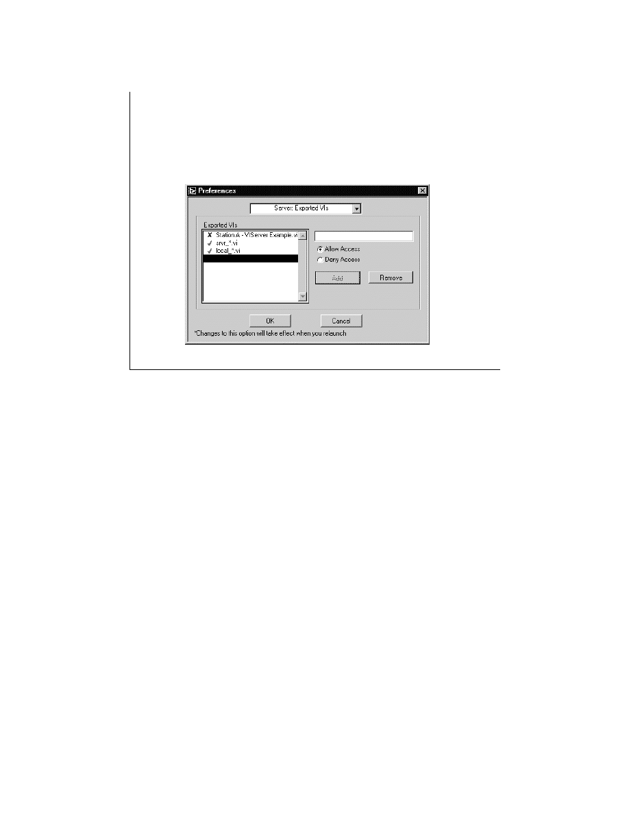
LabVIEW Advanced 1 Course Manual
174
© National Instruments Corporation
LV Adv I 174
Exported VIs Configuration
Select Edit » Preferences and then Server » Exported VIs
from the drop down menu.
When you allow remote applications to access VIs on the VI Server, you should specify
which VIs these applications can access. To configure the exported VIs, select Edit »
Preferences on the server machine and then select Server:Exported VIs from the drop-
down menu. The screen shown on the slide above appears.
This screen allows you to specify which VIs other applications can access through the VI
Server. The Exported VIs list specifies which VIs are exported. To change an entry, select
it from the list then type into the text box at the right of the Exported VIs list. To specify
whether remote computers can or cannot access that VI, click on the Allow Access or
Deny Access radio buttons. Click on the Add button to insert a new entry after the
current selection. Click on the Remove button to delete the current selection. If an entry
allows access to VIs, a check mark appears next to the entry. If an entry denies access to
VIs,
Χ
appears next to the entry. If no symbol appears next to the entry, the syntax of the
entry is incorrect.

LabVIEW Advanced 1 Course Manual
175
© National Instruments Corporation
LV Adv I 175
Exported VIs Configuration
“?” matches exactly one arbitrary character
“*” matches zero or more arbitrary characters
“**” together match zero or more arbitrary
characters including path separator
*
Matches all VIs
/usr/labview/*
Matches all VIs in the directory /usr/labview
Test.vi
Matches any VI named "Test.vi"
*export*
Matches any VI with name that contains the string "export"
OK?
Matches any VI with the name OK?
Examples of Exported VI list entries
Each entry in the Exported VIs list describes a VI name or a VI path and may contain
wildcard characters. When a remote client tries to access a VI, the server examines the
Exported VIs list to determine whether to grant access to the requested VI. If an entry in the
list matches the requested VI, the server either allows or denies access to that VI, based on
how that entry is set up. If a subsequent entry also matches the VI, its access permission is
used in place of the previous permission. If there is not a VI in the list that matches the
requested VI, access to the VI is denied.
The wildcard characters you can use in the Exported VIs list are specified on the slide
above.
You may use the “?”, “*”, and “**” characters. “?” and “*” can be used, but do not include
the path separator. “**” includes the path separator.
The table on the slide above shows some examples of Exported VI list entries using
wildcard characters. The default Exported VIs setting allows access to all VIs.
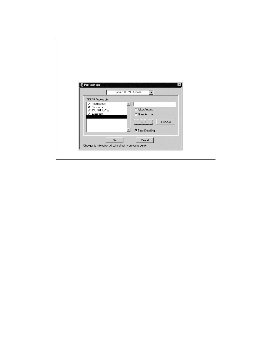
LabVIEW Advanced 1 Course Manual
176
© National Instruments Corporation
LV Adv I 176
TCP/IP Access Configuration
Select Edit » Preferences and then Server » TCP/IP
Access from the drop-down menu.
When you allow remote applications to access the VI Server using the TCP/IP protocol, you
should specify which Internet hosts have access to the server. You can configure the TCP/IP
access permissions in the TCP/IP Access dialog box from the Preferences menu. This box
is shown on the slide above.
The TCP/IP access List describes clients that either have access to or are denied access to the
LabVIEW server. To change an entry, select it from the list, then type into the text box at the
right of the TCP/IP Access list. To specify whether a client has access to the server, click on
the Allow access or Deny access radio buttons. If an address is allowed access, a check mark
appears next to the entry. If an address is denied access, an X appears next to the entry. If no
symbol appears next to the entry, the syntax of the entry is incorrect.
When a client tries to open a connection to the server, the server examines the entries in the
TCP/IP access list to determine whether it grants access to the client. If an entry in the list
matches the client’s address, the server either allows or denies access, based on how you set
up the entry. If a subsequent entry also matches the client’s address, its access permission is
used in place of the previous permission. For example, in the list above, a.test.com is
allowed access even though the list indicates that all addresses ending in test.com are not
allowed access.
An Internet (IP) address, such as 130.164.15.138, may have more than one domain name
associated with it. The conversion from a domain name to its corresponding IP address is
called name resolution. The conversion from an IP address to its domain name is called
name lookup. A name lookup or a resolution can fail when the system does not have access
to a DNS server or when the address or name is not valid. A DNS server is a Domain Name
System server.

LabVIEW Advanced 1 Course Manual
177
© National Instruments Corporation
The Strict Checking option determines how the server treats access list entries that cannot
be compared to a client’s IP address because of resolution or lookup problems.
When Strict
Checking is enabled, a denying access list entry that encounters a resolution problem is
treated as if it matched the client’s IP address. When Strict Checking is disabled, an access
list entry that encounters a resolution problem is ignored.

LabVIEW Advanced 1 Course Manual
178
© National Instruments Corporation
LV Adv I 178
TCP/IP Access Configuration
*
Matches all hosts
test.site.com
Matches the host whose domain name is test.site.com
*.site.com
Matches all hosts whose domain name ends with site.com
130.164.15.138 Matches the host with the IP address 130.164.15.138
130.164.15.*
Matches all hosts whose IP address starts with 130.164.15
Some examples of use of * wildcard in IP addresses
To specify an Internet host address, you can specify either its domain address or IP address.
You can also use the * wildcard when specifying Internet host addresses. The table in the
slide above shows the use of the wildcard character in IP addresses.
Note: If the VI Server runs on a system that does not have access to a DNS server, do not
use domain name entries in the TCP/IP access list. Requests to resolve the domain name
or an IP address will fail, slowing down the system. For performance reasons, place
frequently matched entries toward the end of the TCP/IP Access List.
Next, you will work on an exercise that demonstrates the use of the VI server on a remote
machine.

LabVIEW Advanced 1 Course Manual
179
© National Instruments Corporation
LV Adv I 179
Exercise 2-4
Students will study the communication of client
and server VIs using the LabVIEW VI server.
Time to complete: 10 min.

LabVIEW Advanced 1 Course Manual
180
© National Instruments Corporation
LV Adv I 180
Summary Lesson 2
•
The VI Server concept provides programmatic access
to LabVIEW objects and functionality (that is, control a
VI or LabVIEW itself).
•
All VIs and LabVIEW have properties that can be set
or read and methods that can be invoked using these
VI server functions.
•
The VI Server functionality is exposed through
references to two main classes of objects: the
Application object and the VI object.
•
A strictly-typed VI refnum is a data type that contains
the connector pane information of a VI.
•
LabVIEW 5.0 exports two classes of objects:
Application class and Virtual Instrument class.

LabVIEW Advanced 1 Course Manual
181
© National Instruments Corporation
LV Adv I 181
Summary Lesson 2
•
The LabVIEW VI Server supports its operations on a
local version or a remote version of LabVIEW.
•
For operations on a remote object, the VI Server is
responsible for sending information across the
network and returning results.
•
To configure the VI server, you must select
communication protocols, a list of exported VIs, and
a list of clients that have access to the server.

LabVIEW Advanced 1 Course Manual
182
© National Instruments Corporation
Microsoft ActiveX technology provides a standard model for interapplication
communication that different programming languages can implement on
different platforms. LabVIEW supports the ActiveX Automation and container
technologies. This lesson discusses the Automation Server technology, which
enhances the interactions between LabVIEW and other ActiveX-enabled
applications, such as Microsoft Excel.
LV Adv I 182
Lesson 3
ActiveX Automation Server
You Will Learn:
• About the history of OLE and emergence of
ActiveX
• About ActiveX Automation
• About LabVIEW and ActiveX Automation
• About LabVIEW as an ActiveX Automation
Server

LabVIEW Advanced 1 Course Manual
183
© National Instruments Corporation
OLE incorporates many different technologies that all work toward the goal of seamless
interaction between applications. With OLE, you can create and edit documents that contain
data of different formats, created by multiple applications. These documents are called
compound documents. OLE objects consist of data and a set of methods for manipulating that
data. Objects created maintain the data and also provide an interface through which other
objects can communicate.
The OLE technologies described below are the actions that objects perform:
Linking and Embedding—These are two methods of storing objects inside a
compound document. For example, embedding is placing a spreadsheet inside a
Word document, while linking is saving a link to the spreadsheet file in the
document.
In-Place Activation—For example, if a table from a spreadsheet is embedded in
your document, you could edit the tables with the container application
document.
Automation—For example, programming MS Word from another application
such as LabVIEW or a “C” program.
LV Adv I 183
OLE Technologies
OLE was originally an acronym for Object Linking and
Embedding. Some of the OLE technologies are listed below
:
– Linking and embedding
– In-place activation
– Automation
– Compound files
– Uniform data transfer
– Drag and drop
– Moniker

LabVIEW Advanced 1 Course Manual
184
© National Instruments Corporation
Compound Files—How objects are stored. This technology is useful in implementing a
structured storage technology for creating disk files and improving performance.
Uniform Data Transfer—Data transfer mechanism for objects. For example, an application
can handle clipboard transfers that deal with disk-based storage mediums, such as files,
storage objects, etc.
Drag and Drop—Objects in a Container application respond to mouse clicks. This
technology is useful in moving objects (components) around on pages.
Monikers—An internal object containing information about the link path to a linked
object. A moniker is basically an intelligent name for an object. Monikers are like treasure
maps that know how to follow themselves. All you need to do is say, “Give me treasure,”
and they do everything. Thus, monikers can resolve information to generate an object,
such as loading a file or connecting to a database and sending it a query.
An application that contains these compound documents is called a container application.
A container application can also contain OLE custom controls or OCX, which are now
called ActiveX controls.

LabVIEW Advanced 1 Course Manual
185
© National Instruments Corporation
ActiveX is a diverse set of technologies based on the COM (Component Object Model). The
COM standard allows developers to create code and applications from any of a multitude of
different languages, and build a defined interface to that code, making it easily accessible by
other applications. Applications can access other applications’ functionality through the
standard interface.
Several of the common ActiveX technologies are:
ActiveX Controls are interactive objects that can be used in containers such as a Web site.
ActiveX Documents enables users to view documents, such as Microsoft Word or Excel files,
in an ActiveX container.
Automation enables communication of data and commands between different applications.
Active Scripting controls are the integrated behavior of a lot of ActiveX controls and/or Java
programs from a browser or server.
LV Adv I 185
ActiveX Technologies
ActiveX is a set of technologies that uses the Component Object
Model (COM).
Some of the ActiveX technologies include
– ActiveX controls in containers
– ActiveX documents
– Automation
– Active scripting controls

LabVIEW Advanced 1 Course Manual
186
© National Instruments Corporation
OLE vs. ActiveX: The name OLE denotes the technologies associated with linking and
embedding, including OLE containers, OLE servers, OLE items, in-place activation (or visual
editing), trackers, drag and drop, and menu merging. The name ActiveX applies to the
Component Object Model (COM) and COM-based objects such as ActiveX controls. OLE
Automation is now called Automation.
LV Adv I 186
OLE
• The OLE 2.0 specification was originally a
technology for embedding and linking
objects between software packages.
• As Microsoft began placing emphasis on
Internet, intranet, and active content
technologies, OLE grew into what we now
call
ActiveX
.

LabVIEW Advanced 1 Course Manual
187
© National Instruments Corporation
.ActiveX automation defines the communication protocol between two applications. One
application plays the role of the server, and the other acts as a client.
An automation server exposes methods or actions that can be controlled by a client application.
For example, a spreadsheet application can be an automation server application. Such a server
may expose objects like a spreadsheet, a chart, a range of cells, etc.
An automation client creates and controls objects exposed by a server application. For example,
a LabVIEW program can launch Excel, open an existing spreadsheet, etc.
Recall that we studied that a class defines the type of data contained in an object. An ActiveX
automation object is an instance of a class that exposes properties, methods, and events to
ActiveX clients. An automation object can have both methods or properties. For example, the
methods of a Windows object would be actions you can perform from a Windows control menu,
such as, Restore, Minimize, Maximize, Close, etc. The properties would be functions that
describe the appearance of the window, such as Height, Width, or Window State.
LV Adv I 187
ActiveX Automation
With ActiveX automation, you can:
• Create applications that expose objects - called
automation servers.
• Create and control objects exposed in one
application from another application - called an
automation client.
An automation object can have:
• Methods
- Functions that perform an action on an
object, such as resizing it.
• Properties - Functions that set or return
information about the state of an object.

LabVIEW Advanced 1 Course Manual
188
© National Instruments Corporation
To create and access objects, automation clients need information about a server’s objects,
properties, and methods. Often, properties have data types, and methods return values and
accept parameters.
A list of exposed objects is provided in the type library of the application. A type
library contains specifications for all objects, methods, or properties exposed by an
automation server.
Also, the documentation of the server application contains information about exposed
objects, properties, and methods. The type library file usually has a
.TLB
filename
extension.
LV Adv I 188
ActiveX Automation
To create and access objects, automation clients
need information about a server’s objects,
properties, and methods. This information is
available from the following sources:
• Documentation of that server application.
• Type library of that application. Type Libraries
usually have *.tlb or *.olb extensions.
LabVIEW Advanced 1 Course Manual
189
© National Instruments Corporation
The ActiveX technologies supported by LabVIEW 5.0 are grouped into two categories:
Automation and Container functionalities.
ActiveX Automation: For example, LabVIEW acting as a client can launch Excel, open a
Workbook, etc. You can use a Visual Basic script to control LabVIEW acting as a automation
server.
ActiveX Container: The technology that allows an application to contain (embed) components
from some other software packages. For example, a LabVIEW container can contain a
Microsoft Excel worksheet.
LV Adv I 189
ActiveX Features in LabVIEW 5.0
• Automation Support
Automation Client
Automation Server
• Container Support
SERVER
Excel.exe
labview.exe
CLIENT
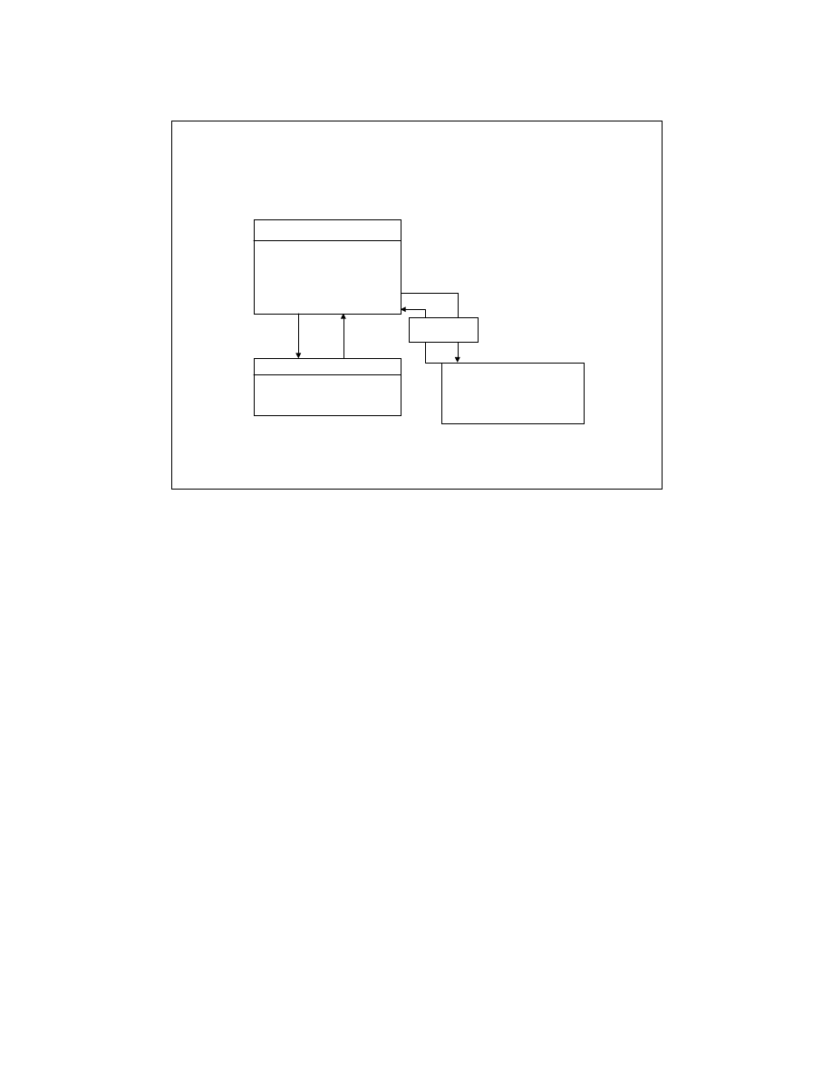
LabVIEW Advanced 1 Course Manual
190
© National Instruments Corporation
Recall that in an earlier lesson, we discussed that LabVIEW supports an ActiveX interface to the
LabVIEW VI Server. This interface is the Automation server interface that allows client
applications to access LabVIEW functionality programmatically.
The graphic shown on the slide above shows how LabVIEW acting as a server interacts with
client applications . LabVIEW’s type library
labview50.tlb
provides information about
LabVIEW objects, methods, and properties. Client Applications can access methods and set or
get properties of the LabVIEW automation server.
LV Adv I 190
LabVIEW as Automation Server
CLIENT APPLICATION
Possible Actions:
Creates Object Instance
Gets an existing object
Get or Sets Properties
Invokes Methods
LabVIEW SERVER
Defines and exposes
Automation objects
Describes
Programmable
Objects
(Maybe part of DLL or standalone)
Maps names to
interface
LabVIEW’s Type Library (labview50.tlb)
Gets Properties
Dispatches Action
Sets Properties
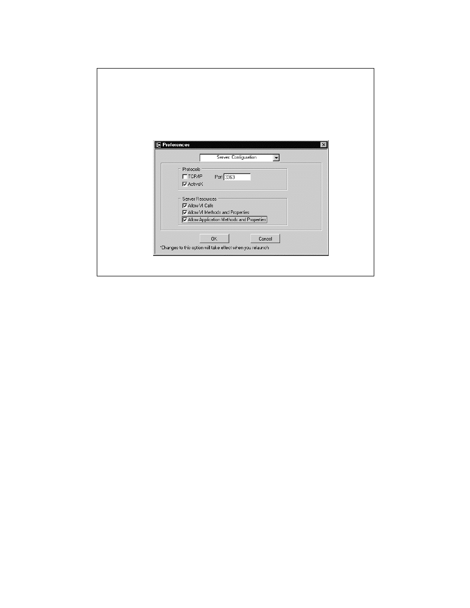
LabVIEW Advanced 1 Course Manual
191
© National Instruments Corporation
LabVIEW can be used as an ActiveX Automation server, so other ActiveX-enabled automation
clients can request properties and methods from LabVIEW and individual VIs. To configure
LabVIEW as an automation server, follow the steps shown on the slide above.
LV Adv I 191
ActiveX Automation Server
To activate LabVIEW as an ActiveX server, select
Edit » Preferences » Server: Configuration. Next, select the
ActiveX protocol.

LabVIEW Advanced 1 Course Manual
192
© National Instruments Corporation
LabVIEW exports a createable class “Application” and a dispatch class “VirtualInstrument”
to ActiveX. The dispatch class allows automation clients to invoke methods and access the
properties of an ActiveX Automation object. A co-class or a createable class is a component
object class and is the top-level object in the object hierarchy.
LV Adv I 192
LabVIEW 5.0 exposes a hierarchy of objects that allow external
applications to control it.
ActiveX Automation Server
LabVIEW 5.0 server objects
• Application Class
• Creatable or “Coclass” class
• GetVIReference method allows access to
VirtualInstrument object
• VirtualInstrument class
• Dispatchable class

LabVIEW Advanced 1 Course Manual
193
© National Instruments Corporation
An application object is created using the progId “LabVIEW.Application” or
“LabVIEW.Application.5”.
LV Adv I 193
Application Object
• Application object - creatable class
progID "LabVIEW.Application"
The following example shows a typical Visual Basic
script for creating an application object.
Dim app as LabVIEW.Application
Set app = CreateObject("LabVIEW.Application")

LabVIEW Advanced 1 Course Manual
194
© National Instruments Corporation
The slide above lists all the properties and methods of the Application Class. Detailed information
about these functions can be found in the online reference manual.
For example, to access the ExportedVIs property information, navigate to Help » Online
Reference » Network and Interapplication Communication » Communication Function and
VI Descriptions » ActiveX Server Application Class Property and Method Descriptions »
Exported VIs in LabVIEW. The Exported VIs property returns a list of VIs in memory.
LV Adv I 194
Application Class
Properties - Application Class
AllVIsInMemory PrintSetupCustomDiagram
AppKind
PrintSetupCustomDiagramHidden
ApplicationDirectory
PrintSetupCustomDiagramRepeat
AppName PrintSetupCustomHierarchy
AppTargetCPU PrintSetupCustomHistory
AppTargetOS PrintSetupCustomPanel
AutomaticClose PrintSetupCustomPanelBorder
ExportedVIs PrintSetupCustomSubVIs
OSName PrintSetupCutomControlTypes
OSVersion
PrintSetupFileWrapText
PrintSetupCustomConnector PrintSetupJPEGQuality
PrintSetupCustomControlDesc PrintSetupPNGCompressLevel
PrintSetupCustomControls UserName
PrintSetupCustomDescription Version
Methods - Application Class
BringToFront
GetVIReference
MassCompile
Quit

LabVIEW Advanced 1 Course Manual
195
© National Instruments Corporation
The Application method GetVIReference creates and returns a pointer to a VI object. In the slide
above, a typical Visual Basic script is shown to instantiate a virtual instrument object for test.vi.
LV Adv I 195
Virtual Instrument Class
• Virtual Instrument class - dispatchable class.
• A Virtual Instrument object exports properties and
methods that affect a given VI.
To instantiate a Virtual Instrument object for a
“test.vi”:
Dim vi as LabVIEW.VirtualInstrument
Set vi = app.GetVIReference("c:\myVIs\test.vi")

LabVIEW Advanced 1 Course Manual
196
© National Instruments Corporation
All the properties and methods of the Virtual Instrument class are listed above. All function
details are available in the online reference.
LV Adv I 196
Virtual Instrument Class
Properties
AllowDebugging
FPWinPanelBounds
BDModificationBitSet FPWinTitle
BDSize HelpDocumentPath
Callees HelpDocumentTag
Callers HistAddCommentsAtSave
CloseFPAfterCall HistoryText
CodeSize HistPromptAtClose
DataSize HistPromptForCommentsAtSave
Description HistRecordAppComments
EditMode HistUseDefaults
ExecPriority IsReentrant
ExecState LogAtFinish
FPAllowRTPopup LogFilePath
FPAutoCenter Name
FPHiliteReturnButton Path
FPIsDialog PreferredExecSystem
FPModificationBitSet PrintLogFileAtFinish
FPResizable RevisionNumber
FPShowMenuBar RunOnOpen
FPShowScrollBars ShowFPOnCall
Methods
Call PrintVIToPrinter
ExportVIStrings
PrintVIToRTF
GetControlValue
PrintVIToText
GetLockState
ReinitializeAllToDefault
GetPanelImage
Revert
ImportVIStrings
Run
MakeCurValueDefault
SaveInstrument
PrintPanel SetControlValue
PrintVIToHTML
SetLockState
Properties
FPSize ShowFPOnLoad
FPSizeToScreen
SuspendOnCall
FPTitleBarVisible TBShowAbortButton
FPWinBounds TBShowFreeRunButton
FPWinClosable TBShowRunButton
FPWinCustomTitle TBVisible
FPWinIsFrontMost VIModificationBitSet
FPWinOpen VIType
FPWinOrigin
LabVIEW Advanced 1 Course Manual
197
© National Instruments Corporation
The slide above shows the flowchart for programming LabVIEW automation server’s objects,
properties, and methods. The first step for a client application is to create a reference to the
LabVIEW application by accessing the object LabVIEW.Application. Then you get or set
properties or execute methods of the Application object. Next, you should access a specific VI
by getting a reference to it. Once you have a reference or pointer to your VI, you can manipulate
the properties and methods of your VI. Finally, you should release Application and VI
references.
The next three exercises use this programming model.
LV Adv I 197
Flowchart for Accessing
LabVIEW Server
Create an Object
LabVIEW.Application
Get/Set Properties
of Application Object
Execute Methods
Of Application Object
Execute Method
GetVIReference Of
Application object
Get/Set Properties
of Virtual Instrument Class
Execute Methods
Of Virtual Instrument Class
Close References to
Application Object

LabVIEW Advanced 1 Course Manual
198
© National Instruments Corporation
LV Adv I 198
Exercise 3-1
Students will observe and run a macro written in
Visual Basic script to run a VI and tabulate results.
Time to complete: 10 min.

LabVIEW Advanced 1 Course Manual
199
© National Instruments Corporation
LV Adv I 199
Exercise 3-2
Students will complete and run a macro written in
Visual Basic script to run a VI and tabulate results.
Time to complete: 10 min.

LabVIEW Advanced 1 Course Manual
200
© National Instruments Corporation
LV Adv I 200
Exercise 3-3
Students will examine and run a C++
program written in Visual C++ to access
the LabVIEW Automation server.
Time to complete: 10 min.

LabVIEW Advanced 1 Course Manual
201
© National Instruments Corporation
LV Adv I 201
Summary Lesson 3
•
LabVIEW 5.0 supports ActiveX technologies such as
automation and container functionalities.
•
Using ActiveX automation, software components can
communicate using a client/server model.
•
An automation client accesses objects that have been
exposed by an automation server.
•
An automation server is an application that exposes
objects.
•
The LabVIEW 5.0 application can function as an
automation server.
•
A user-defined VI can function as an automation
client.
•
LabVIEW 5.0 exports two classes of objects:
Application class and Virtual Instrument class.

LabVIEW Advanced 1 Course Manual
202
© National Instruments Corporation
LV Adv I 202
Lesson 4
ActiveX Automation Client
and ActiveX Container
You Will Learn:
• About LabVIEW as an ActiveX
Automation Client
• About LabVIEW’s Automation functions
• About LabVIEW as a client to Excel
• About Remote Automation
• About LabVIEW as an ActiveX Container
Introduction
This lesson continues to discuss the different ActiveX technologies that LabVIEW supports.
First, you will be introduced to the Automation Client capabilities of LabVIEW, followed by
remote automation technology. Finally, Automation Control capabilities will be introduced.
LabVIEW Advanced 1 Course Manual
203
© National Instruments Corporation
LV Adv I 203
LabVIEW as an ActiveX
Automation Client
LabVIEW CLIENT
Possible Actions:
Creates object instance
Gets an existing object
Get or sets properties
Invokes methods
ACTIVEX AUTOMATION
SERVER
Defines and exposes
Automation objects
Describes
Programmable
Objects
(Maybe part of DLL or standalone)
Maps names to
interface
Gets properties
Dispatches action
Sets properties
Type Library
LabVIEW allows users to write VIs that function as automation clients. These VIs access the
exposed objects of automation servers to get and set the properties of those objects and invoke
their methods.
The diagram shown on the slide above shows how LabVIEW, acting as a ActiveX automation
client, interacts with server applications. LabVIEW accesses the server’s type library to obtain
information about its objects, methods, and properties. LabVIEW can perform actions such as
invoking methods, getting or setting properties, etc.
LabVIEW Advanced 1 Course Manual
204
© National Instruments Corporation
LV Adv I 204
LabVIEW’s ActiveX Client
Functions
To communicate with ActiveX
Automation servers, use the
following functions in
LabVIEW:
Choose Functions »
Communication » ActiveX
palette.
You will find the tools for creating ActiveX automation client VIs in the Functions palette
under Communications » ActiveX.
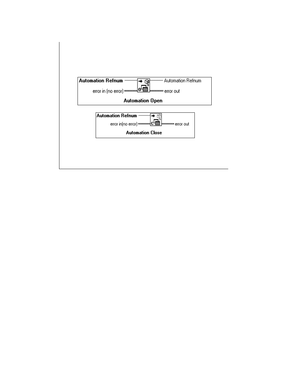
LabVIEW Advanced 1 Course Manual
205
© National Instruments Corporation
LV Adv I 205
Automation Function Descriptions
Open Automation Refnum
The Open Automation Refnum function opens an automation refnum that refers to a specific
ActiveX Automation object. You can select the class of the object by popping up on the
function and selecting Select ActiveX class.
You should select only createable classes as inputs to this function. This list of createable
objects is generated by accessing the Windows Registry. Once you create a refnum, it can be
passed to other ActiveX functions.
Close Automation Refnum
The Close Automation Refnum function closes an automation refnum. Make sure that you
close every automation refnum when you longer need it.
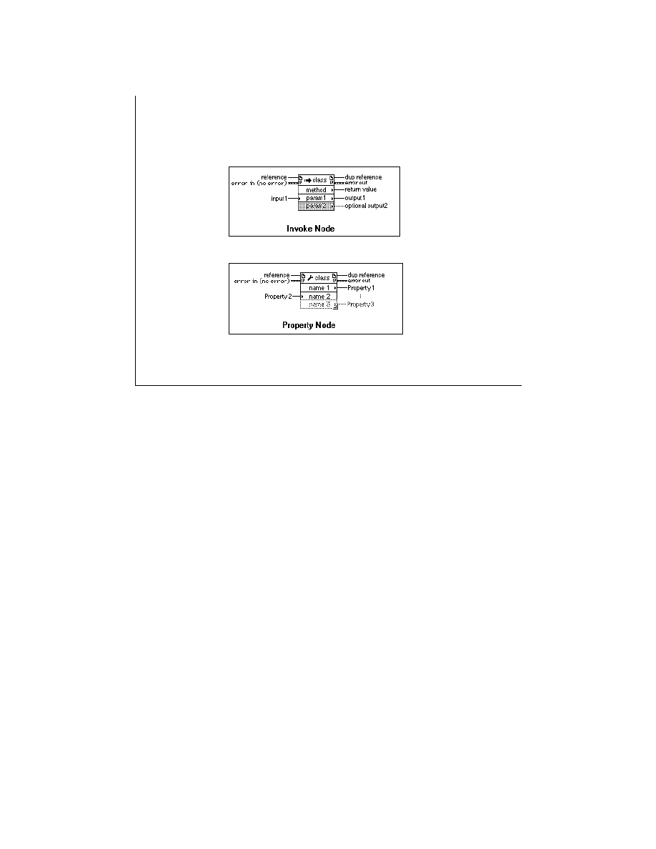
LabVIEW Advanced 1 Course Manual
206
© National Instruments Corporation
LV Adv I 206
Automation Function Descriptions
Invoke Node
Invoke Node function invokes a method or an action on an ActiveX automation object. To choose an
ActiveX class object, pop up and choose Select » ActiveX Class. Or wire an automation refnum to the
input. To select a method related to the object, pop up on the second section of the node and select
Methods. Once you select a method, the appropriate parameters appear automatically below it.
Parameters with white backgrounds are required inputs and the parameters with a gray background are
optional inputs.
Property Node
The Property Node function sets or gets ActiveX object property information. To select an ActiveX class
object, pop up and choose Select » ActiveX class. Then to select a property related to that object, pop up
on the second line of the node and select Properties. To set property information, pop up and select
Change to Write. To get property information, pop up and select Change to Read.
Some properties are read-only or write only, hence Change to write or Change to Read, respectively,
is grayed out in the pop-up menu.
The property node works the same way as Attribute nodes. If you want to add items to the node, pop up
and select Add Element or click and drag the node to expand the number of items in the node.
Note: The Property node and Invoke node functions on the ActiveX subpalette and Application
Control subpalette (VI Server) are the same. The same interface is used to access both ActiveX objects
and references to VIs through the VI Server. The nodes are replicated to be logically near the
subpalette with which they can be used.
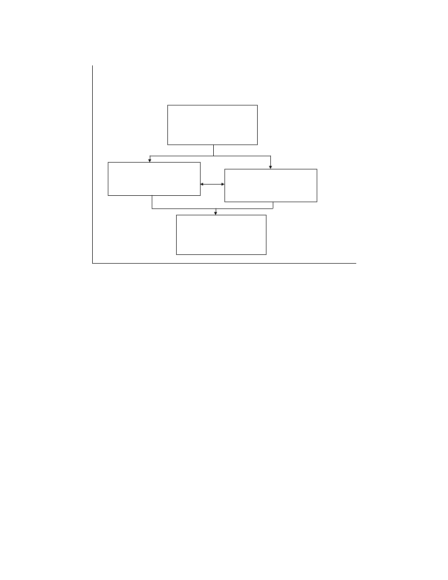
LabVIEW Advanced 1 Course Manual
207
© National Instruments Corporation
LV Adv I 207
Flowchart for Automation
Functions
Open a Reference
to Automation Server
Using
Automation Open Function
Get/Set Properties Using
Property Node Function
Invoke Methods Using
Invoke Node Function
Close the Reference
to Automation Server
Using
Automation Close Function
The flow chart in the slide above depicts the order in which automation functions can be used to
communicate with an Automation server.
When writing an automation client VI, you first open a reference to the automation server using
the Automation Open function. You choose which automation server you want to use by
popping up on the Automation Refnum input of this function and select ActiveX Class…
Choose the server from the list of available automation servers on your system.
Use the returned reference number to get or set property values using the Property Node and
invoke methods using the Invoke Node function. Finally, you close the reference to the
automation server with the Automation Close function.
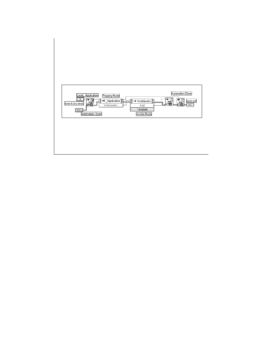
LabVIEW Advanced 1 Course Manual
208
© National Instruments Corporation
LV Adv I 208
Automation Example
The example shown above adds a Workbook to Microsoft Excel from LabVIEW. In this
example, first you open an Excel refnum with Open Automation Refnum function. This
launches Excel. Then you can access the workbook refnum with the Property Node. After you
add a workbook to Excel, a refnum referring to that Workbook is returned to LabVIEW. When
you no longer need Excel to be open, you must close the Excel and Workbook refnum.
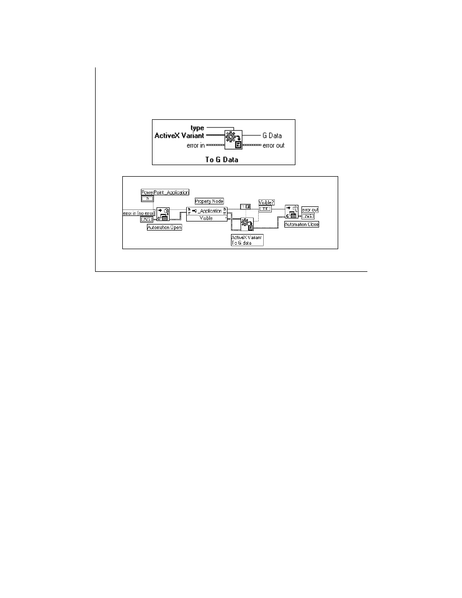
LabVIEW Advanced 1 Course Manual
209
© National Instruments Corporation
LV Adv I 209
Data Conversion Function
ActiveX Variant to G data
This is a data conversion function and converts ActiveX Variant data to data that can be displayed
in LabVIEW.
Some applications provide ActiveX data in the form of a self-describing data type called an
ActiveX or OLE Variant. To view the data or process it in G, you must convert it to the
corresponding G data type.
The example shown above shows how to convert ActiveX Variant data to G data. In this example,
you open the application object of Microsoft PowerPoint and display the Visible property using
the Property Node.
The Visible Property returns the data in ActiveX Variant format. The G Data Function then
converts the property information to a format supported by LabVIEW, which in this case is a
Boolean.
Note: If you are writing a property of ActiveX variant type, you can wire the LabVIEW/G data
types and they will be automatically converted to variant data types, and this will be indicated by
a coercion dot.
LabVIEW Advanced 1 Course Manual
210
© National Instruments Corporation
LV Adv I 210
Table of New and Old
ActiveX Functions
New ActiveX Functions
Automation Open
Automation Close
Invoke Node
Property Node
Old ActiveX Functions
Create Refnum
Release Refnum
Execute Method
List Methods or Properties
Get Property
Set Property
ActiveX support from LabVIEW 5.0 onward has changed from LabVIEW 4.x. LabVIEW
ActiveX client programming has been simplified.
LabVIEW still supports the old OLE Automation functions using compatibility functions. But, all
new applications should be built using the new ActiveX functions. The table above shows how
old functions map to the new functions.

LabVIEW Advanced 1 Course Manual
211
© National Instruments Corporation
LV Adv I 211
Automation with LabVIEW
and Excel
• Objects - Every unit of content and functionality in
Excel is an object.
Examples: A Workbook, a Worksheet
• Object Models - Access Excel online help to view
the Excel object Models by selecting Help »
Content » Index » Microsoft Visual Basic Reference.
• Object Models can also be found at
http://www.microsoft.com/officedev/articles/OMG
Objects are discrete units of related content and functionality in an application. Examples of
objects are Microsoft Excel workbooks, worksheets, cell ranges, etc. An object hierarchy or the
object model is the way in which objects that make up an application are arranged relative to
each other.
The Microsoft Excel object hierarchy can be found in the Microsoft Visual Basic reference in the
Help menu. Excel objects are arranged hierarchically with an object named Application at the
top of the hierarchy. All other objects fall under Application. To call the properties and methods
of an object in Excel, you must reference all objects that lie on the hierarchical path to that
object. For example, to access the Chart object, you must first access the Application object, the
Workbook object, and then the Chart object.

LabVIEW Advanced 1 Course Manual
212
© National Instruments Corporation
LV Adv I 212
Exercise 4-1
Students will examine and run a VI using
ActiveX Automation calls to access
Microsoft Excel to input values.
Time to complete: 10 min.

LabVIEW Advanced 1 Course Manual
213
© National Instruments Corporation
LV Adv I 213
Exercise 4-2
Students will examine and run a VI that
changes the text and font style of an
existing chart in Microsoft Excel using
ActiveX Automation calls from a
LabVIEW VI.
Time to complete: 10 min.

LabVIEW Advanced 1 Course Manual
214
© National Instruments Corporation
LV Adv I 214
Exercise 4-3
Students will complete and run an
Automation Client VI that controls an
ActiveX Automation Server.
Time to complete: 10 min.

LabVIEW Advanced 1 Course Manual
215
© National Instruments Corporation
LV Adv I 215
Remote Automation
• Automation across the network is implemented
using DCOM.
• DCOM (Distributed Component Object Model).
• DCOM is a technology for software applications to
communicate across the network.
• DCOM is supported only on Windows 95/NT/98.
DCOM (the Distributed Component Object Model) is a Microsoft technology that allows
software applications to communicate directly with each other across networks. You will be able
to communicate over the network using ActiveX remote automation to build distributed
applications.
LabVIEW 5.0 supports remote automation by using DCOM. Thus, ActiveX clients can leverage
off DCOM to communicate with LabVIEW running on a remote machine.
Note: DCOM is supported only on the Windows 95/NT/98 operating systems.
Next, we will discuss some of the issues in using DCOM.

LabVIEW Advanced 1 Course Manual
216
© National Instruments Corporation
LV Adv I 216
Limitations of Remote
Automation
At present, you cannot communicate between two
copies of LabVIEW on different machines.
• The client LabVIEW will intercept all the calls to
the server.
You cannot do remote activation if the server is on
a Windows 95 machine.
• LabVIEW has to be launched manually on the
server machine.
DCOM is a very complex technology and it can be very confusing while you are trying to use
it to configure an application. There are several security issues that must be considered.
Note: Before we discuss this further, consider the two limitations of DCOM and LabVIEW:
1.
You cannot communicate between two copies of LabVIEW on different machine. The
client LabVIEW will intercept all calls to the server.
2.
You cannot do remote activation if the server is on a Windows95/98 machine.
LabVIEW must be launched manually on the server machine.
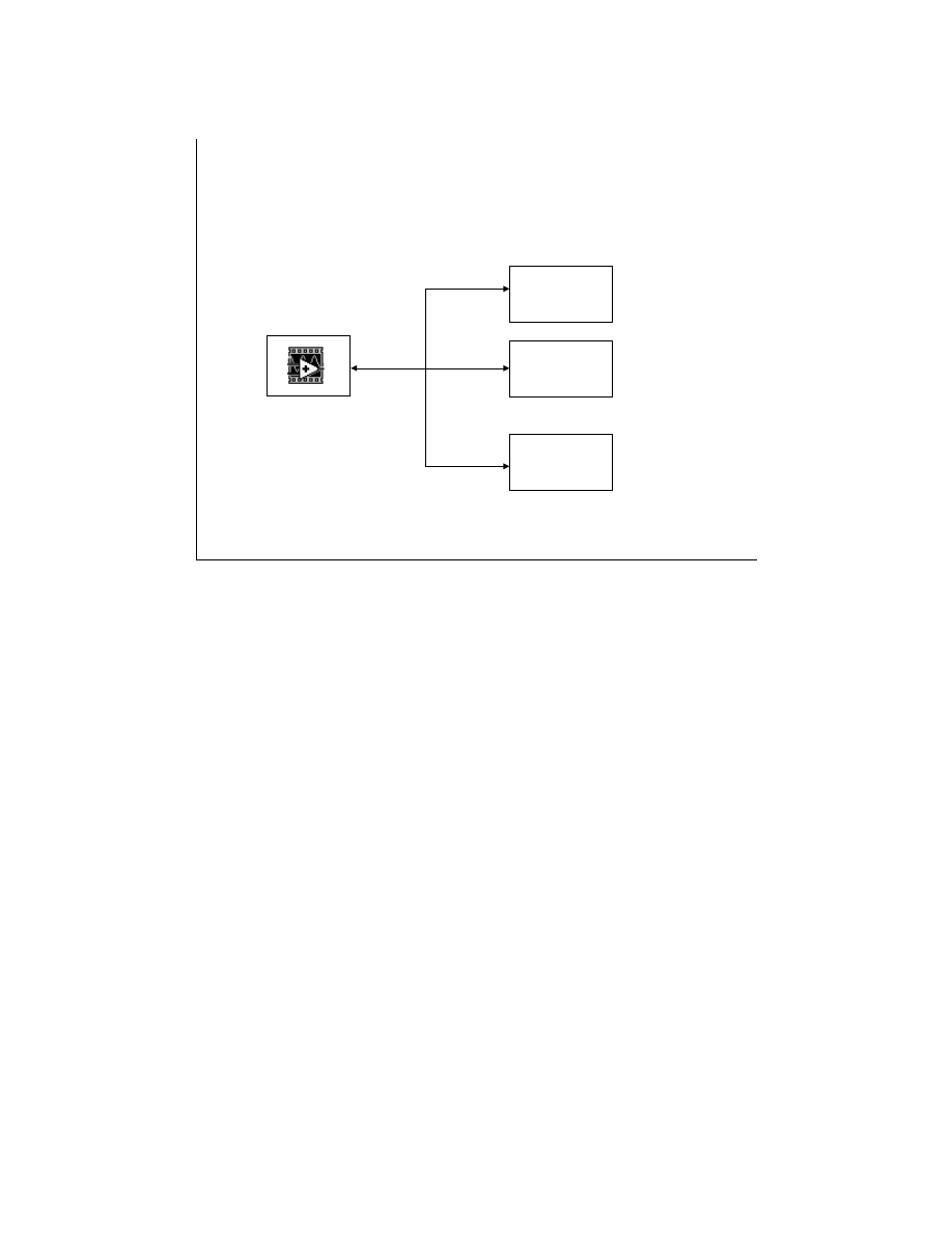
LabVIEW Advanced 1 Course Manual
217
© National Instruments Corporation
LV Adv I 217
Configuring DCOM
SERVER
On
Windows 95/NT/98
Client 1 on
Windows
95/NT/98
Client 2 on
Windows
95/NT/98
Client 3 on
Windows
95/NT/98
To use LabVIEW 5.0 and ActiveX remote automation, you need a Windows NT server machine
and one or more client machines running Windows 95 or NT. LabVIEW 5.0 should be installed
on the server machine. You should configure DCOM on both the server and client machines.
DCOM is configured differently on Windows 95 and Windows NT machines.
If you have a Windows NT or Windows 95 machine available to set up as a server or a client,
all the detailed instructions for configuring the server and client are attached in the Appendix
section of this manual.

LabVIEW Advanced 1 Course Manual
218
© National Instruments Corporation
LV Adv I 218
ActiveX Container
A container application can:
• Embed controls
- Controls have Automation Interface
- Controls can be programmed from using
that interface
• Embed/link documents
- Documents may or may not have
Automation interface
An application acting as an ActiveX container can contain objects from other software packages.
An ActiveX container can contain two types of objects: controls and documents.
A control is an ActiveX object that you can act on directly. An example of an ActiveX control
could be the Microsoft Web browser. All controls have an automation interface that allows you
to work with them programmatically.
Documents are objects that you can either link to or embed in a container. When you link to a
document with a container, you establish a “view” to that document. Any changes to that
document are reflected in the container application. When you embed a document, the document
now becomes a part of the container application. If you make any changes to the document
outside of the container application, the container will not see these changes. Some documents,
like Microsoft Excel charts, additionally have an automation interface that allows you to work
programmatically with them. An example of an ActiveX document is a Microsoft Word
document embedded in a PowerPoint application.
A LabVIEW 5.0 VI can act as an ActiveX container.
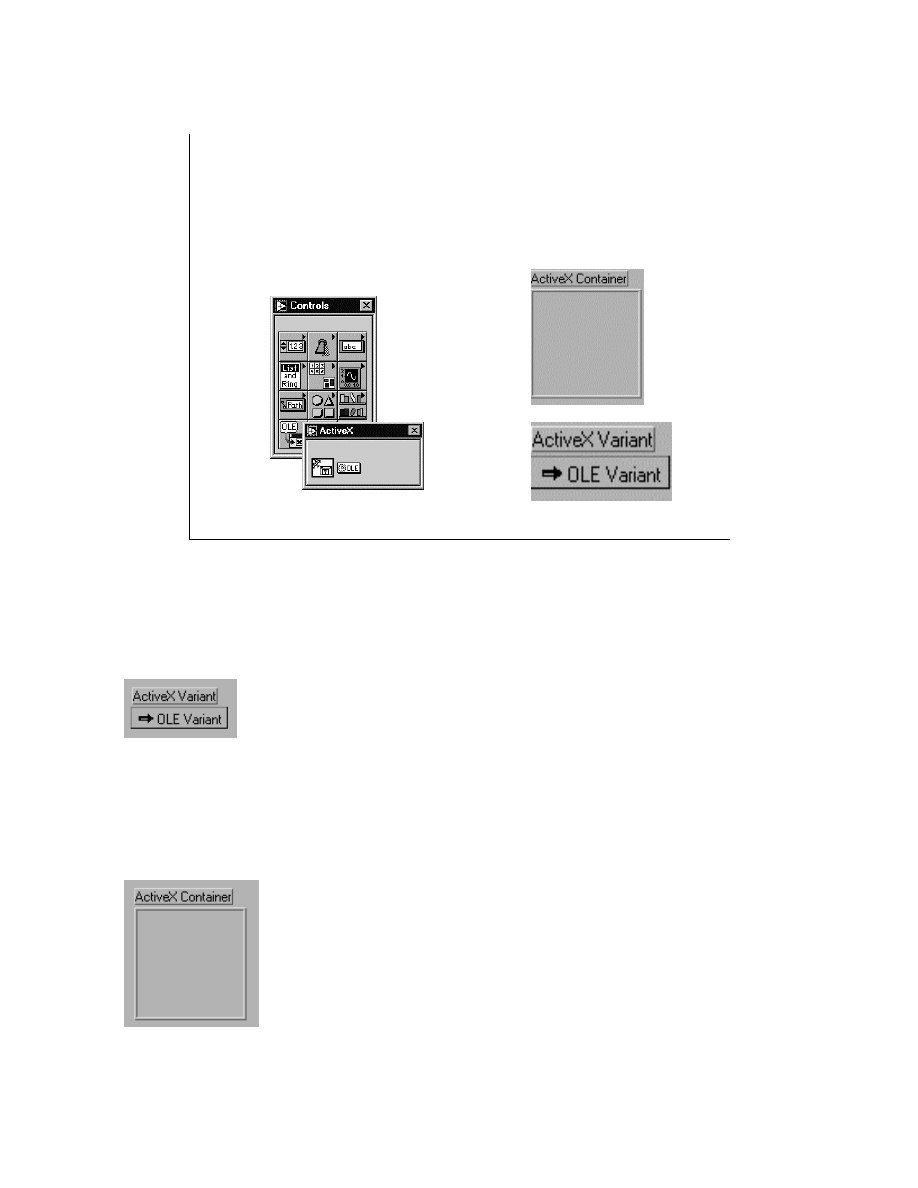
LabVIEW Advanced 1 Course Manual
219
© National Instruments Corporation
LV Adv I 219
LabVIEW as an ActiveX Container
To access LabVIEW’s new ActiveX control subpalette,
select Controls » ActiveX
The two new controls in LabVIEW, ActiveX Container and ActiveX Variant, as shown in the slide above
enable you to take advantage of the ActiveX Container capability.
ActiveX Variant Control and Indicator
The ActiveX Variant control and indicator allows you to pass ActiveX Variant data into LabVIEW.
When you place the ActiveX Variant control and indicator on the block diagram, it appears as follows:
Use this front panel object when ActiveX Variant data is converted to data that LabVIEW can display.
ActiveX Container
The ActiveX container manipulates data on ActiveX objects. You can use this container to display
ActiveX controls and embedded documents on the front panel. When you place the ActiveX Container on
the front panel, it appears as:
The ActiveX Container appears as an automation refnum terminal on the block diagram. You can wire
this terminal to Automation functions and control the object embedded in the container.
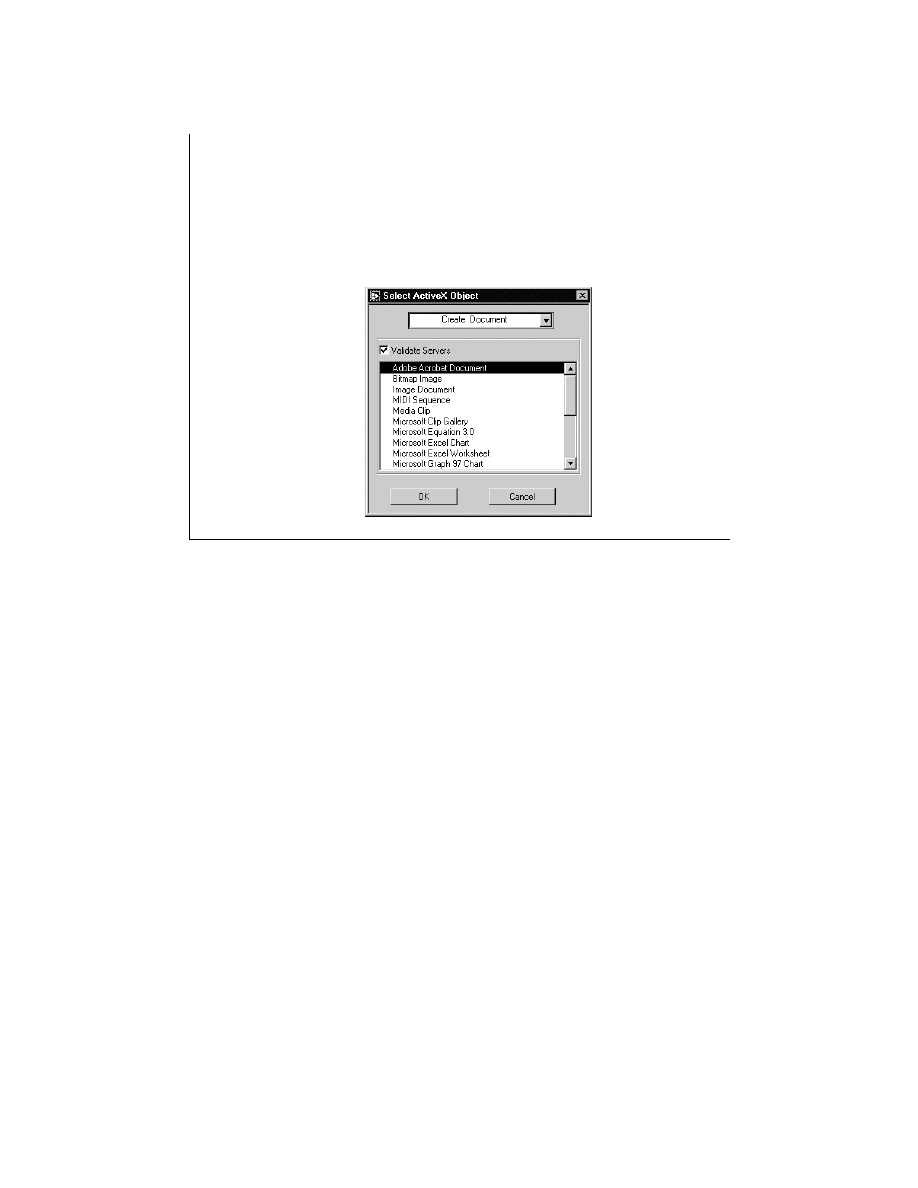
LabVIEW Advanced 1 Course Manual
220
© National Instruments Corporation
LV Adv I 220
LabVIEW as an ActiveX Container
To insert a document in the ActiveX Container:
Pop up, select Insert ActiveX Object, and select
Create Document
ActiveX Documents and Controls are the two types of objects that can be contained in the
ActiveX Container (like LabVIEW 5.0).
ActiveX Documents
These objects can be contained by the container object and can be edited by popping up and
selecting the Edit Object option. This brings up a new window to edit the object. Some
documents support automation and can be manipulated by automation functions on the diagram.
ActiveX Controls
These objects can be activated and operated on inside the container. Because they support
automation, they can be controlled by automation functions on the diagram.
In LabVIEW, objects can be dropped in the Container by choosing one of the three ways shown
in the menu selection at the top of the Select ActiveX Object dialog box.
Create Document—Choose a document registered with your system.
Create Object from File—Choose a document from a file located anywhere on your file
system. This object can either be linked to the file or can be statically copied into the panel.
Create Control—Choose a control registered on your system.
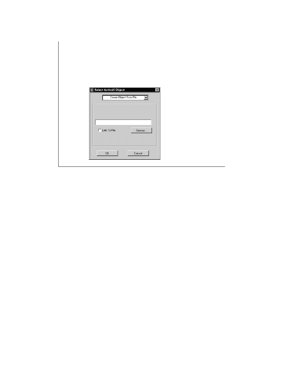
LabVIEW Advanced 1 Course Manual
221
© National Instruments Corporation
LV Adv I 221
LabVIEW as an ActiveX Container
To insert an object from file, select
Create Object From File, and the dialog box changes:
To insert an existing document or file into an ActiveX Container, select Create Object from
File. Then you can use Browse… to find the document for insertion.
If the Link To File option is selected, the document is updated when the front panel object is
updated. If this option is not selected, a static version of the document is inserted.
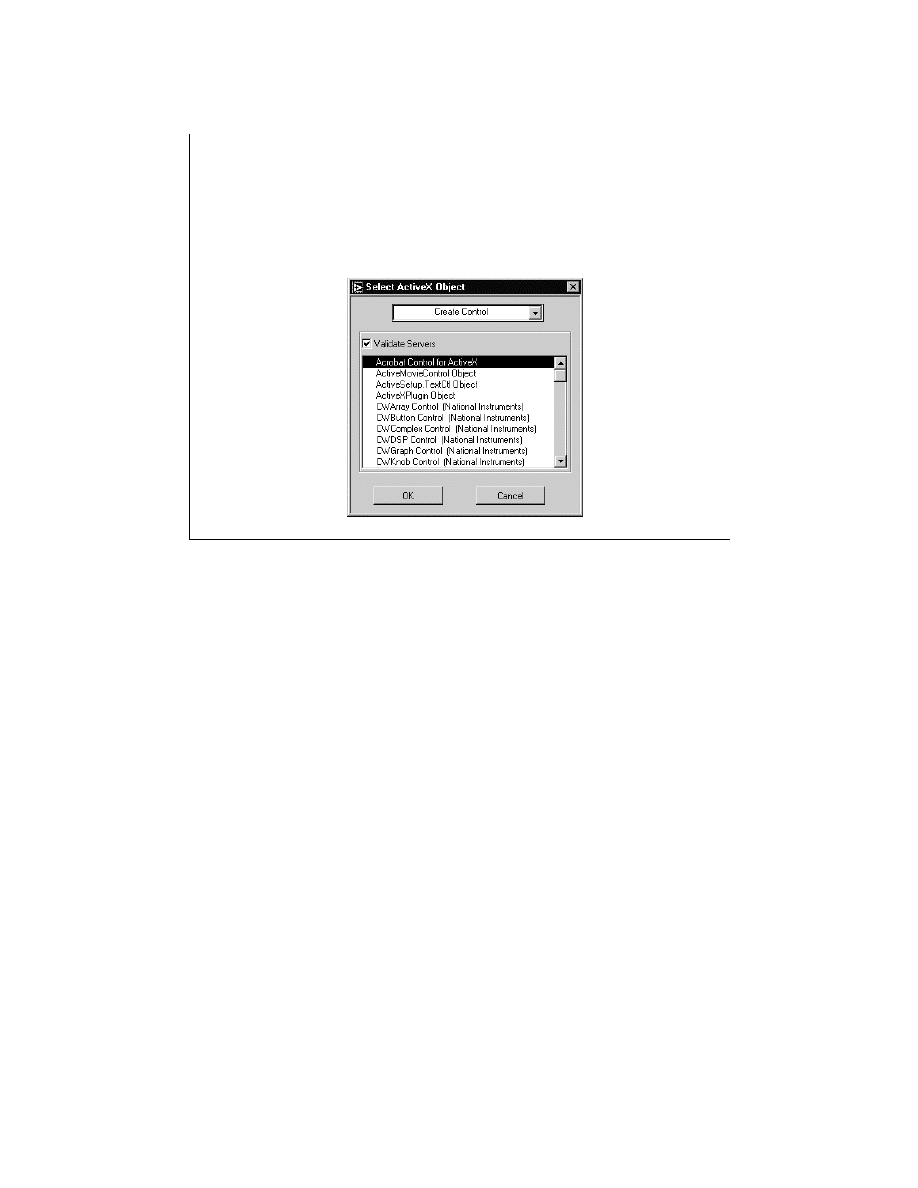
LabVIEW Advanced 1 Course Manual
222
© National Instruments Corporation
LV Adv I 222
LabVIEW as an ActiveX Container
To insert an existing control, select
Create Control, and the dialog box changes:
To insert an existing control into an ActiveX Container, select Create Control. All the available
control types are registered with your system.
Once you insert an object in the ActiveX container, because it appears as an automation refnum
terminal on the block diagram, you can wire it to the Automation functions we discussed earlier
and control the object embedded in the container.
Note: If an object does not support an Automation interface, the terminal will have an invalid
refnum and cannot be used with the Automation functions.
You will now work on exercises that demonstrate how you can use the Automation functions to
control the ActiveX container objects.

LabVIEW Advanced 1 Course Manual
223
© National Instruments Corporation
LV Adv I 223
Exercise 4-4
Students will create a Web Browser
Object using an ActiveX Control
in LabVIEW.
Time to complete: 10 min.

LabVIEW Advanced 1 Course Manual
224
© National Instruments Corporation
LV Adv I 224
Exercise 4-5
Students will complete a VI to control
different ActiveX controls through the
LabVIEW ActiveX Container Control.
Time to complete: 15 min.

LabVIEW Advanced 1 Course Manual
225
© National Instruments Corporation
LV Adv I 225
Summary of Lesson 4
•
LabVIEW allows users to write VIs that function as
automation clients.
•
To create an automation client VI
:
1. Open a reference to the Automation Server.
2. Use the returned reference to get/set properties.
3. Use the reference to invoke methods.
4. Close the reference to the Automation Server.
•
When you receive ActiveX data in G/LabVIEW, that
data format is called an
ActiveX Variant.
•
The Microsoft Excel object hierarchy defines the way
in which objects are arranged relative to one another.

LabVIEW Advanced 1 Course Manual
226
© National Instruments Corporation
LV Adv I 226
Summary Lesson 4
•
A LabVIEW 5.0 VI can act as an ActiveX container.
Hence, it can embed two types of objects: controls
and documents.
•
An ActiveX Container appears as an automation
refnum terminal on the LabVIEW block diagram, and it
can be wired to automation functions for
programming.

LabVIEW Advanced 1 Course Manual
227
© National Instruments Corporation
LV Adv I 227
LabVIEW Advanced I Course
Module 3
Calling External Functions
TM
National Instruments
11500 N. MoPac Expressway
Austin, Texas 78759
(512) 683-0100
Introduction
LabVIEW is a graphical programming language rich in data acquisition, data analysis,
and data presentation capabilities. Usually, the VIs included in the LabVIEW
Development System meet the needs of most users. However, if you have existing
applications written in C or if you want to implement a task that is difficult to
accomplish within the block diagram, you can use CINs (Code Interface Nodes) or
DLLs (Dynamic Link Libraries).
This module teaches you to write CINs and simple DLLs. The module discusses CIN
basics first, and then you will learn about the various LabVIEW manager functions,
basic data types, and pointers and handles. You also will learn how parameters are
passed from LabVIEW to CINs and external subroutines, and how to call DLLs from a
CIN. In addition, you will learn about the LabVIEW Call Library Function, which
calls DLLs directly, and how to write DLLs using LabWindows/CVI and Visual C++.
Hands-on exercises reinforce the various concepts.
Course Description
The LabVIEW Calling External Functions module teaches you to write and call CINs
and DLLs. The course is divided into lessons, each covering a topic or a set of topics.
Each lesson consists of:
•
An introduction that describes the lesson’s purpose and what you will learn.
•
A discussion of the topics
•
A set of exercises to reinforce the topics presented in the discussion.
•
A summary that outlines important concepts and skills taught in the lesson.

LabVIEW Advanced 1 Course Manual
228
© National Instruments Corporation
LV Adv I 228
National Instruments Technical Support Options
Telephone Support (USA):
Fax
.............................................................
(512) 683-5678
Telephone
...........................................
(512)
683-8248
Fax-on-Demand: 24-hour information retrieval system with
a library of documents
.............…
(512) 683-1111
Internet Support:
Web Support - searchable Knowledgebase, support
documents, and files
................
http://www.natinst.com
.......................................................
support@natinst.com
FTP - contains support files and documents to download
FTP Site:
ftp.natinst.com
login:
anonymous
password:
your Internet address
Listed above are the various ways you can contact National Instruments for technical support.

LabVIEW Advanced 1 Course Manual
229
© National Instruments Corporation
LV Adv I 229
Course Goals
• Learn the basics of writing Code Interface Node code
• Understand how to pass parameters to LabVIEW
• Understand how to call LabVIEW manager functions
• Understand how to write and call external subroutines
• Understand how to call DLLs through CINs
• Understand how to call DLLs through the LabVIEW Call
Library Function.
• Understand how to write DLLs using the Visual C++
compiler and the LabWindows/CVI compiler
• Understand about multithreading with CINs and DLLs
• Understand how to troubleshoot DLLs
This course prepares you for the items listed above.

LabVIEW Advanced 1 Course Manual
230
© National Instruments Corporation
LV Adv I 230
Course Non-Goals
• To teach LabVIEW basics
• To teach programming theory
• To discuss every built-in LabVIEW object,
function, or library VI
• To teach C/C++ programming
• Win95 or Win32 API programming
• The development of a complete application
for any student in the class
It is not the purpose of this course to discuss any of the items listed above.
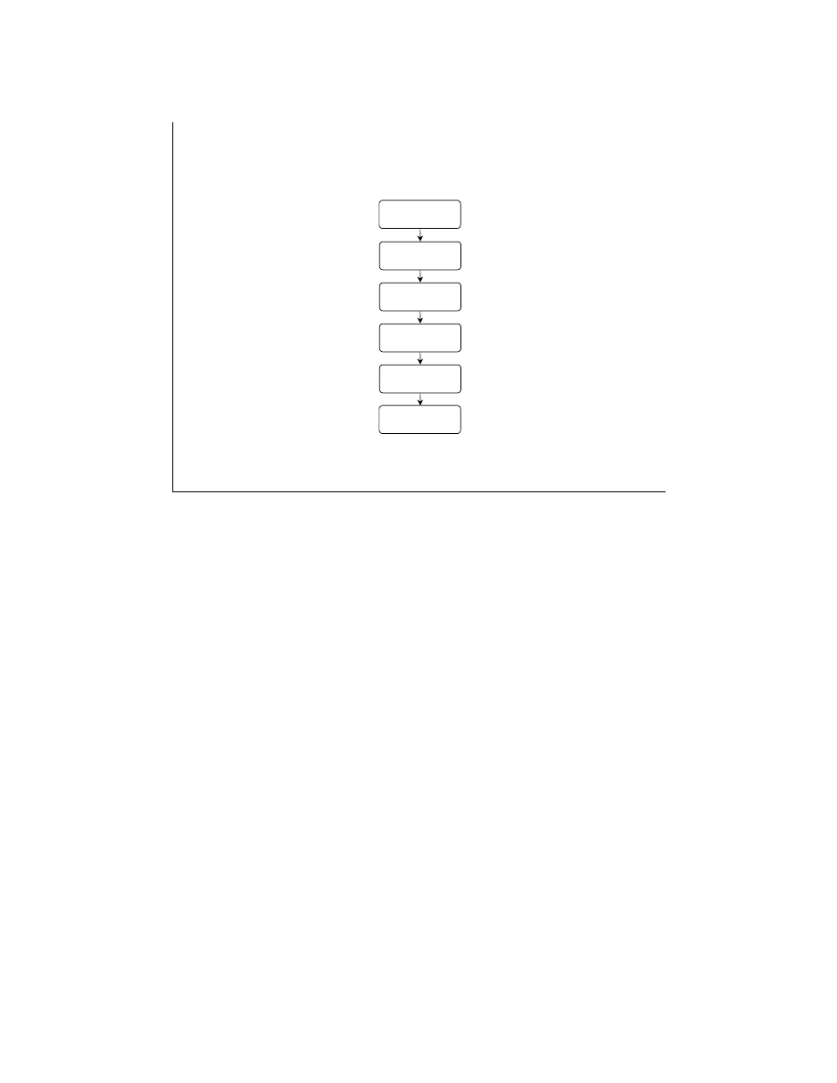
LabVIEW Advanced 1 Course Manual
231
© National Instruments Corporation
LV Adv I 231
Module Outline
CIN Basics
LabVIEW
Manager Functions
Passing
Parameters
Advanced Topics
Calling DLLs
Writing DLLs
The LabVIEW Calling External Functions Module covers the following topics.
Lesson 1:
CIN Basics
Break
Lesson 2:
LabVIEW Manager Functions
Break
Lesson 3:
Passing Parameters
Lunch
Lesson 4:
Advanced Topics
Break
Lesson 5:
Calling DLLs
Break
Lesson 6:
Writing DLLs
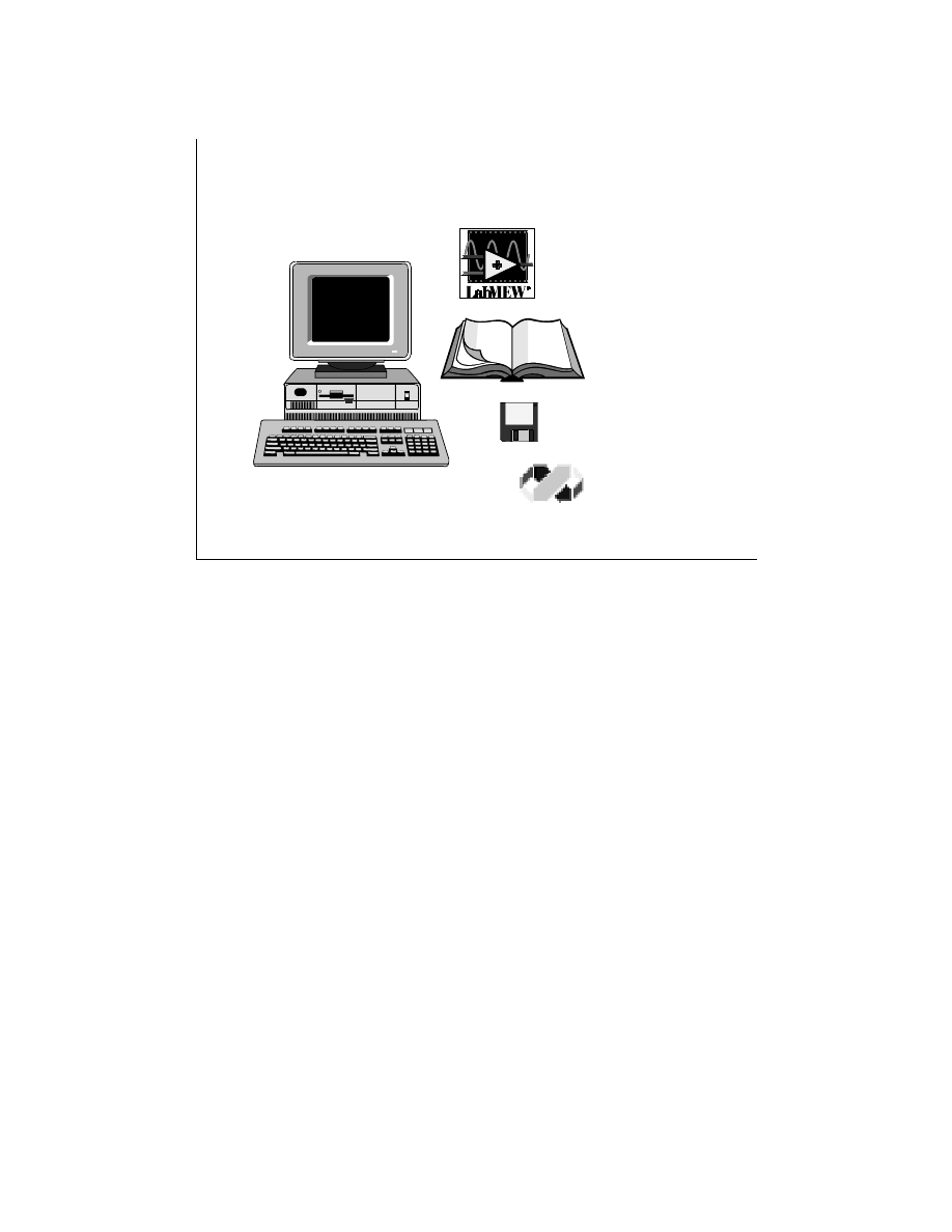
LabVIEW Advanced 1 Course Manual
232
© National Instruments Corporation
LV Adv I 232
Equipment Needed for this Course
Computer running Windows 95/NT
LabVIEW for Windows
ver. 5.0 or later
LabVIEW Advanced I
Course Manual
LabVIEW Advanced I
Course Disks
Microsoft Visual C++
5.0 (Optional)
Items You Will Need for this Course Module:
•
Computer running Windows 95 or Windows NT
•
LabVIEW for Windows Full Development System, ver. 5.0 or later
•
LabVIEW Advanced I Course Manual and Disks
•
Optional—A word processing application such as Notepad or Wordpad
•
Optional—Microsoft Visual C++ 5.0
•
Optional—LabWindows/CVI compiler
•
MIO Series DAQ board
•
DAQ Signal Accessory
Install the course software by inserting the third course disk and double-clicking on the file
Module3.exe.
Extract the contents of this self-extracting archive into your
C:\
directory.
All of the files you need will be installed into the
C:\Exercises\LV_AdvI
directory. The
solutions to all the exercises will be installed into the
C:\Solutions\LV_AdvI
directory.
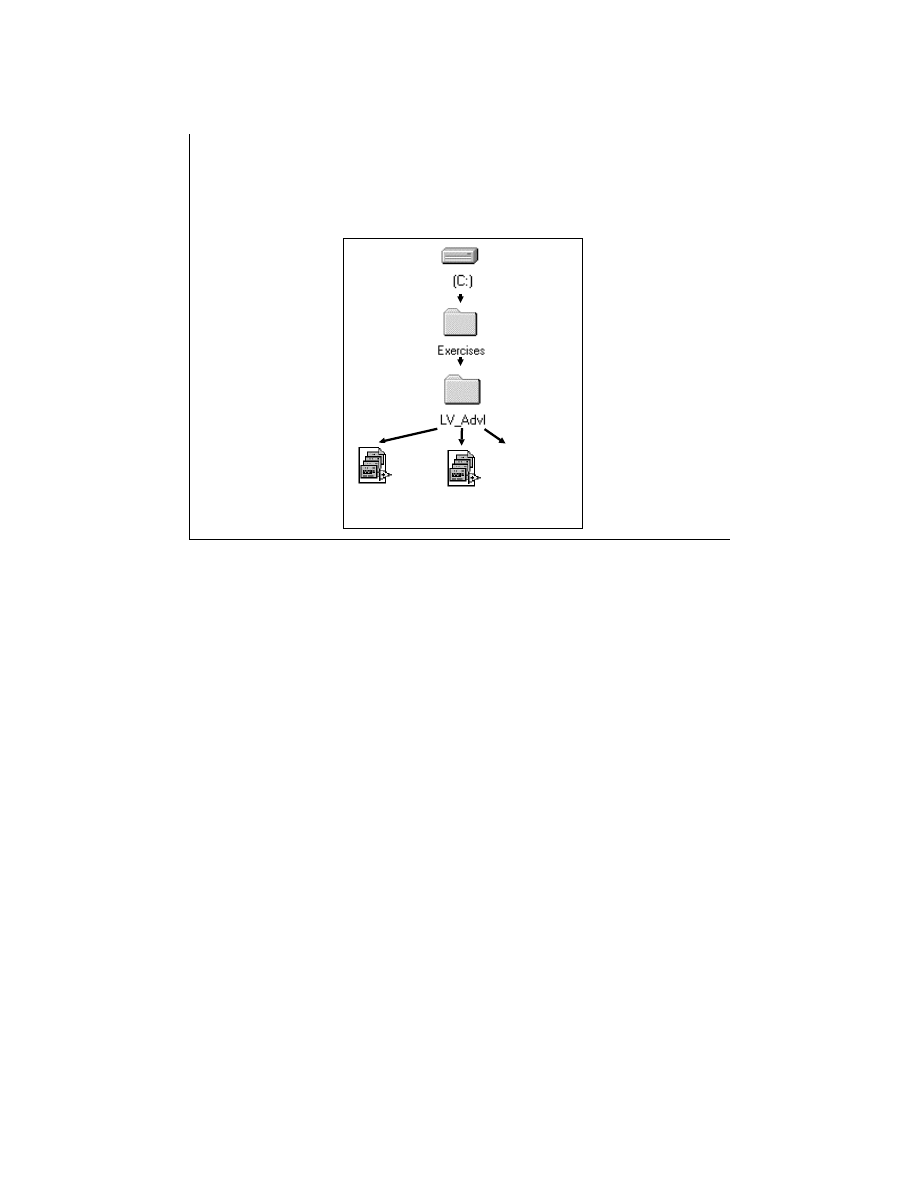
LabVIEW Advanced 1 Course Manual
233
© National Instruments Corporation
LV Adv I 233
Hands-On Exercises
• Exercises reinforce the topics presented
• Save exercises into the VI libraries shown here:
Dllclass.llb
cinclass.llb
C FILES
SOURCES
acquire.dll
ourdll.dll
resize.dll
firstdd.dll
concat.dll

LabVIEW Advanced 1 Course Manual
234
© National Instruments Corporation
LV Adv I 234
Lesson 1
CIN Basics
You Will Learn:
• When to use CINs or DLLs
• What a CIN is
• Advantages and disadvantages of using CINs
• What compilers are supported for WIN32
• How to create a simple CIN
This lesson discusses basic Code Interface Node (CIN) concepts.

LabVIEW Advanced 1 Course Manual
235
© National Instruments Corporation
LV Adv I 235
When to Use CINs and DLLs
There are three common reasons for you to
write CINs or DLLs:
• You have existing C code that you want to
use within a VI.
• You need to talk with hardware that LabVIEW
does not directly support.
• You want to implement something that is
impossible or impractical in the context of a
block diagram.
LabVIEW is a graphical programming language rich in data acquisition, data analysis, and data
presentation capabilities. It includes VIs to acquire data from plug-in data acquisition boards,
programmable instruments, and other applications. LabVIEW also includes VIs that analyze
data and present results through a graphical user interface.
In most cases, the VIs and functions included in the LabVIEW development system meet the
needs of users. However, if you have existing applications written in a traditional language, you
would like to implement a task that cannot be done directly from the diagram (such as calling
system routines for which no corresponding LabVIEW functions exist), or you would like to
perform a task that is time-critical or requires a great deal of data manipulation, you can use
CINs or DLLs. DLLs are called through the LabVIEW Call Library function.
In summary, there are three common reasons for you to write CINs or DLLs:
•
You have existing C code that you want to use within a VI.
•
You need to talk with hardware that LabVIEW does not directly support.
•
You want to implement a task that is impossible or impractical in the context of a block
diagram.

LabVIEW Advanced 1 Course Manual
236
© National Instruments Corporation
LV Adv I 236
When to use CINs or DLLs
• Except on Windows 3.1, DLLs can perform most
tasks that CINs and external subroutines can with
a couple of exceptions.
• DLLs cannot be stored inside VIs or LLBs.
• DLLs do not support CIN-specific procedures
such as CINLoad, etc.
The call library node in LabVIEW calls a 16-bit Windows 3.1 DLL or a 32-bit Windows
95/NT DLL. In Windows 3.1, there are certain limitations due to which you cannot use
LabVIEW-specific datatypes such as the LabVIEW String Handle or Adapt to Type.
Hence, Windows 3.1 DLLs cannot modify LabVIEW data types.
Unlike CINs, DLLs cannot be stored inside VIs or LLBs, because LLBs are LabVIEW-
specific VI libraries. So, if you use DLLs, you must ship them along with your LLBs.
Also, DLLs cannot support CIN-specific procedures such as CINLoad.
Hence, if you do not need to modify LabVIEW datatypes or do not need to use CIN-
specific procedures, you may choose to write a DLL instead of a CIN.
LabVIEW Advanced 1 Course Manual
237
© National Instruments Corporation
LV Adv I 237
Code Interface Nodes
A Code Interface Node (CIN) is a LabVIEW function
that links external code written in a conventional
programming language to LabVIEW.
Applications
– Time-critical events
– Large set of data manipulations
– Numerically intensive calculations
– Calls to system routines
– Link to an existent code (that is, Windows DLL)
– Control non-National Instruments hardware
sub()
{ }
Code Resource
VI
A Code Interface Node (CIN) is a LabVIEW function that links external code written in a
conventional programming language to LabVIEW.
You compile the source code and link it to form an executable code resource. LabVIEW calls the
executable code when the code interface node executes, passing input data from the block
diagram to the executable code, and returning data from the executable code to the block
diagram.
External Subroutines
An external subroutine is a section of code you can call from other external code, such as
CINs and other shared external subroutines. If you write multiple CINs that call the same
subroutine, you may want to make the shared subroutine an external subroutine. The code
for an external subroutine is a separate file; when LabVIEW loads a section of external code
that references an external subroutine, it also loads the appropriate external subroutine into
memory. Using an external subroutine makes each section of calling code smaller, because
the external subroutine does not require embedded code. Further, you need to make changes
only once if you want to modify the subroutine.

LabVIEW Advanced 1 Course Manual
238
© National Instruments Corporation
LV Adv I 238
Issues of Using CINs
• CINs execute synchronously (that is, LabVIEW
cannot use the execution thread used by the CIN
for any other purpose).
• When LabVIEW runs in a multithreaded mode,
there is a separate thread for monitoring user
interface tasks.
• If LabVIEW has only a single thread of control, all
of LabVIEW is stopped until the CIN object code
executes.
• In multithreaded operating systems such as
Windows 95/NT/98, only the execution thread
running the CIN is locked up.
Issues of Using CINs
CINs execute synchronously, which means that LabVIEW cannot use the execution thread
used by the CIN for any other purpose. When a VI executes, LabVIEW monitors menus and
the keyboard. When running multithreaded, there is a separate thread for these tasks. When
running single-threaded, the VI returns to LabVIEW to allow it time to scan menus and the
keyboard, and run other VIs or applications.
When CIN object code executes, it takes control of its execution thread. If LabVIEW is
running in a single-threaded mode, all of LabVIEW is stopped until the CIN object code
executes. On single-threaded operating systems such as Macintosh and Windows 3.1, CINs
even prevent other applications from running. In multithreaded operating systems such as
Windows 95/NT/98, only the execution thread running the CIN is locked up. However, if
there is only one execution thread, other VIs are prevented from running.
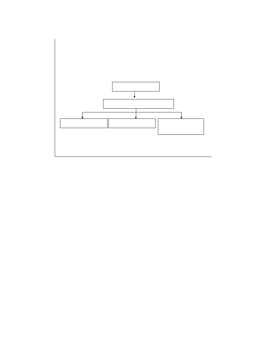
LabVIEW Advanced 1 Course Manual
239
© National Instruments Corporation
LV Adv I 239
LabVIEW supplies the header, libraries, objects, and
applications files used for the compiler utilities to create code
resource. The following compilers are supported:
CIN Tools
CINTOOLS
Windows 95/NT/98
Microsoft Visual C++
Symantec C Compiler
Watcom C Compiler
for Win 3.1 under
Windows 95/NT/98
The interface for CINs and external subroutines supports a variety of compilers, although
not all compilers can create code in the correct executable format. External code must be
compiled as a form of executable appropriate for a specific platform. The code must be
relocatable, because LabVIEW loads external code into the same memory space as the
main application. LabVIEW supplies CIN tools, including the header files, applications,
utilities, and other files you need to develop CINs in the different programming
environments for each platform.
All the compilers supported by LabVIEW on the Windows platform are listed above.
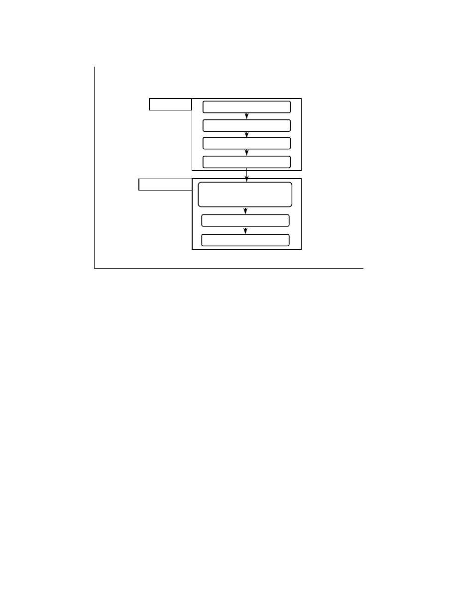
LabVIEW Advanced 1 Course Manual
240
© National Instruments Corporation
LV Adv I 240
How to Create a Simple CIN
LabVIEW
Place CIN Function
Add I/O terminals
Wire all I/O terminals
Create the .c file
C Compiler
Load the .lsb file
Run the VI
Write the external function
and build the code resource
into .lsb format
The figure above outlines the basic steps for creating a CIN.
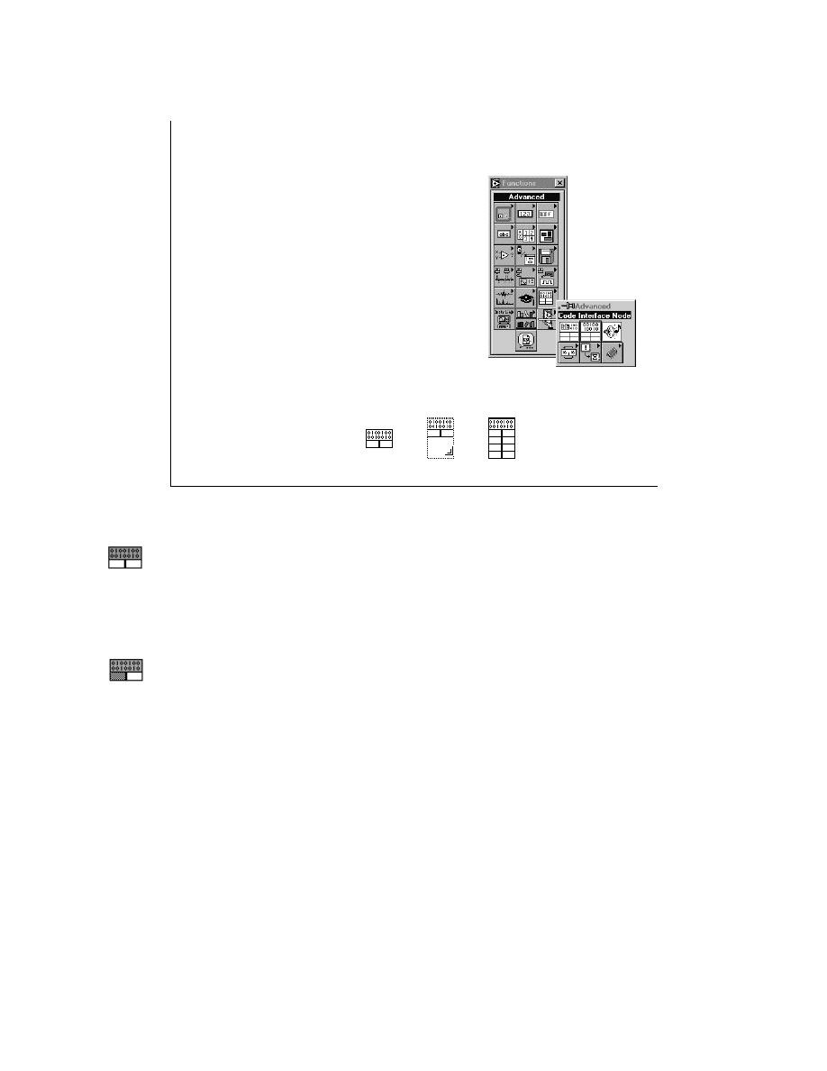
LabVIEW Advanced 1 Course Manual
241
© National Instruments Corporation
LV Adv I 241
1. Place the CIN function
To place a CIN icon on the
block diagram, select it from
the Advanced subpalette of
the Functions palette.
2. Add Input and Output Terminals
Resize the node to add parameters,
or select Add Parameters from the
CIN pop-up menu.
Creating a CIN
Input-Output Terminals
By default, a terminal pair is an input-output terminal that accepts and returns data.
Output Only Terminals
The Output Only option from the CIN terminal pop-up menu defines a parameter that
returns only data. If a terminal pair is output only, the input terminal is gray.
When the VI calls the CIN, the only argument that LabVIEW passes to the CIN object
code is a pointer to the value in the input terminal. When the CIN finishes executing,
LabVIEW receives the value that the output terminal references.
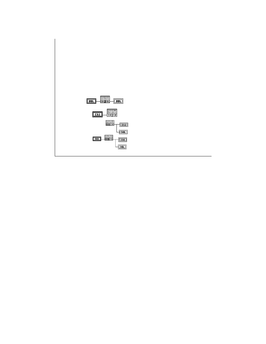
LabVIEW Advanced 1 Course Manual
242
© National Instruments Corporation
LV Adv I 242
Creating a CIN
3. Wire all the input and output terminals
Connect wires to all the terminal pairs on the CIN to
specify the data that you want to pass to the CIN.
Input-Output
The CIN can modify the data
passed
The CIN will not modify the data
passed
The output terminal adapts to
the data type connected to the
left terminal
Output Only
Connect wires to all the terminal pairs on the CIN to specify the data you want to pass to
the CIN. The order of terminal pairs on the CIN corresponds to the order of the parameters
in the CIN routine. You can use any LabVIEW data types as CIN parameters.
LabVIEW sets the terminal data type based on what you wire to the terminal. If you are
using numeric controls and indicators, be sure to set the data type for the object by using
the Representation option from the Object pop-up menu.
If you do not wire an indicator to the output terminal of a terminal pair, LabVIEW assumes
that the CIN will not modify the value you pass to it. If another node uses the input data,
LabVIEW does not make a copy of the data.
Note: If you don’t wire the output terminal, the source code should not modify the value
passed into the input terminal. Nodes connected to the input terminal wire may receive the
modified data.
An output-only terminal, which has an object connected to the left terminal of the terminal
pair, adapts itself to the type of that object. If nothing is wired to the left terminal,
LabVIEW determines the output terminal type by checking the data type of the indicator
wired to the output terminal. If the output terminal is wired to more than one object,
LabVIEW uses the first valid type it finds.
The example above shows the CIN with one output terminal. Assume that the desired output
terminal type is a 32-bit float (SGL). In the top figure, LabVIEW selected the wrong data type
(as the gray dot on the SGL indicator indicates). This problem is corrected in the lower figure by
wiring a 32-bit floating-point (SGL) variable to the left terminal

LabVIEW Advanced 1 Course Manual
243
© National Instruments Corporation
LV Adv I 243
Creating a CIN
4. Create the .c File
Create the .c file by selecting
Create .c File... from the CIN
pop-up menu
/*
* CIN source file
*/
#include "extcode.h"
CIN MgErr CINRun(float64 *var1, int32 *var2, LVBoolean *var3);
CIN MgErr CINRun(float64 *var1, int32 *var2, LVBoolean *var3) {
/* ENTER YOUR CODE HERE */
return noErr;
}
When you select Create .c file... from the CIN pop-up menu, LabVIEW creates a
.c
file in
the style of the C programming language. The
.c
file describes the routine you must write
and the data types that pass to the CIN.
The code shown on the slide above is the initial
.c
file for its node. Eight routines may be
written for a CIN. The CINRun routine is a required routine and hence its function structure
is defined in the initial
.c
file. These eight routines are described in detail later in the
lesson.
Notice that
extcode.h
is automatically included; it is a file that defines basic data types
and a number of routines that can be used by CINs and external subroutines. CINRun is the
only routine that deals with input and output parameters. The order of the variables
corresponds to the order given by the CIN terminal pairs. In this example, the first
parameter is the float64 (DBL), the second parameter is an int32 (I32), and the third
parameter is an LVBoolean (TF).

LabVIEW Advanced 1 Course Manual
244
© National Instruments Corporation
LV Adv I 244
Creating a CIN
Note:
LabVIEW passes generic data types to create code that works
identically across multiple platforms
.....
CIN MgErr CINRun(float64 *var1, int32 *var2, LVBoolean
*var3);
.....
LabVIEW Data Types
Visual C++
floatExt
(EXT)
long double*
float64
(DBL)
double
float32
(SGL)
float
int32
(I32)
long (int)
int16
(I16)
short int
int8
(I8)
char
uint32
(U32)
unsigned long int
uint16
(U16)
unsigned short int
uint8
(U8)
unsigned char
LVBoolean
(T/F)
unsigned short int
* The long double
data type (80-bit,
10-byte precision)
is mapped to
double (64-bit,
8-byte precision)
in Windows NT.
Because the
.c
file is intended for use with C programming languages, the file uses
generic references that make it possible to create a code that works identically across
multiple platforms.
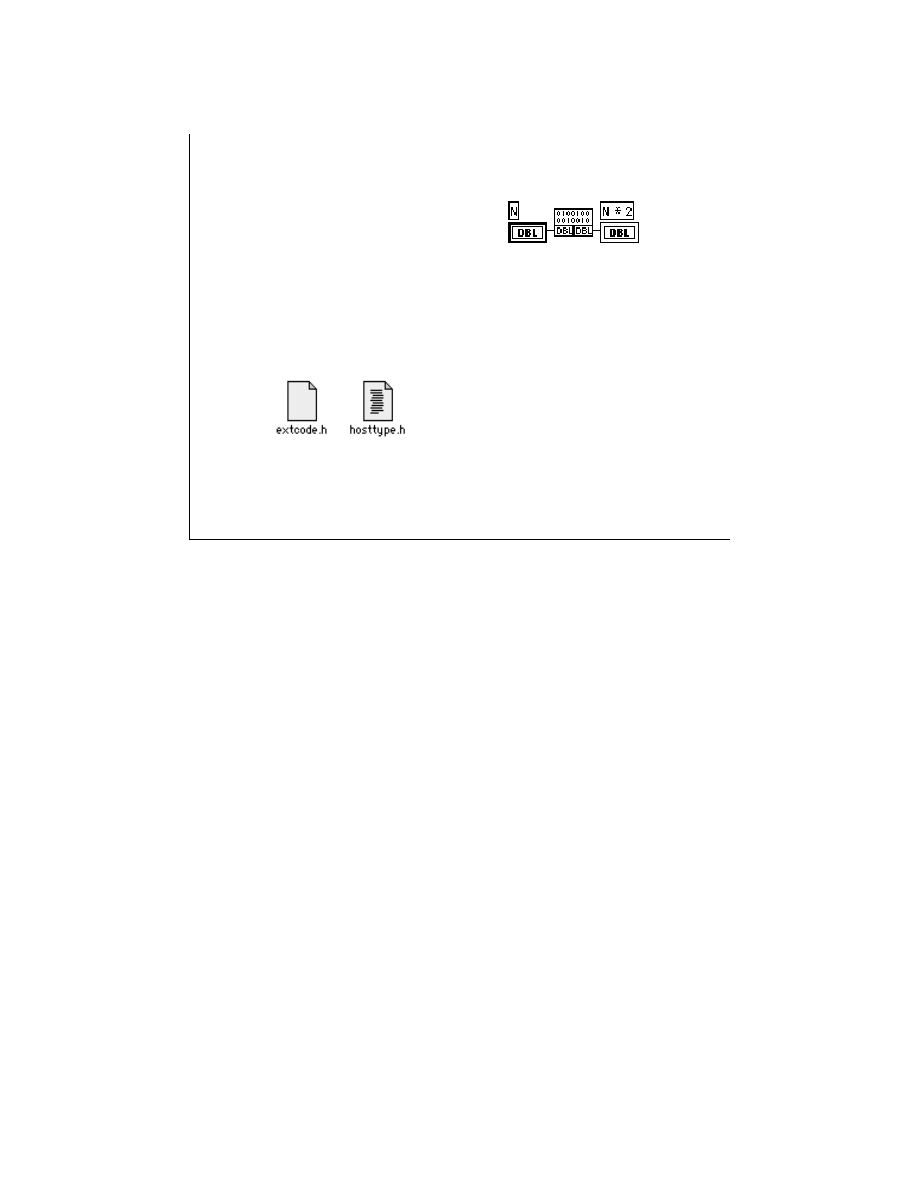
LabVIEW Advanced 1 Course Manual
245
© National Instruments Corporation
LV Adv I 245
Creating a CIN
5. Create the CIN Source Code
The code for CIN consists of eight
routines that LabVIEW calls when
it is time for the CIN to execute
and in response to several other
events. When LabVIEW calls
CINRun, it sends the input and
receives the output value
parameters.
/*
* CIN source file
*/
#include "extcode.h"
CIN MgErr CINRun(float64 *N);
CIN MgErr CINRun(float64 *N)
{
*N = *N * 2.0;
return noErr;
}
Note:
You should always include the
extcode.h
header file. The
hosttype.h
file resolves platform-dependent issues
Write the C code for your CIN in the
.c
file. LabVIEW supplies two basic header files
to help you build the CIN:
extcode.h
You always should include
extcode.h
at the beginning of your
source code, before you include your other header files. It defines basic
data types and a number of routine prototypes that CINs and external
subroutines can use.
extcode.h
defines some constants and types
whose definitions may conflict with the definitions of system header
files.
hosttype.h
If your code needs to make system calls, include
hosttype.h
immediately after
extcode.h
.
hosttype.h
resolves the differences
between
extcode.h
and the system header files. It also includes a
subset of header files for a given operating system. If the
.h
file you
need is not included by
hosttype.h
, you can include it in the
.c
file
for your CIN immediately after you include
hosttype.h
.
The code for a CIN consists of eight routines that LabVIEW calls when it is time for the
CIN to execute and in response to several other events. When LabVIEW calls the CIN,
the CINRun routine receives the input and output parameters. The other routines—
CINInit, CINDispose, CINAbort, CINLoad, CINUnload, and CINSave, CINProperties—
are housekeeping routines called at specific times to take care of specialized tasks with
your CIN.
The slide above shows an example CIN for multiplying a number by two.
LabVIEW Advanced 1 Course Manual
246
© National Instruments Corporation
LV Adv I 246
Creating a CIN
When does LabVIEW call the CIN routines?
Note:
The CINInit and the CINDispose functions work as a
pair. You can clean up in CINDispose what you set up in
CINInit.
The CINLoad and the CINUnload functions work as a
pair. You can clean up in CINUnload what you set up in
CINLoad
.
Loading VI Compiling VI Running VI Saving VI Closing VI Aborting VI
CINInit CINDispose CINRun CINSave CINDispose CINAbort
CINLoad CINInit CINProperties CINUnload
CINInit
Called immediately after the block diagram compiles, or each time
LabVIEW loads a VI that contains the CIN into memory. Use this routine
to initialize data, allocate memory for data structures, or perform other
setup procedures.
CINDispose Called when you close the VI containing a CIN or before calling another
CINInit. You can use this routine to dispose of data structures allocated in
memory with CINInit, and for other cleanup operations.
CINAbort
Called for every reference to a given code resource when the VI is aborted
while the diagram containing a CIN executes. If a VI is aborted, CINAbort
also is called for any active subVIs containing a CIN. This routine is useful
for aborting pending asynchronous I/O.
CINRun
Contains the code to perform the task for which the CIN is designed. It
receives the input parameters and returns any output parameters.
CINLoad
Called when you load the VI containing a CIN for the first time or when
the object code is loaded into a VI. LabVIEW passes a parameter of type
RsrcFile (a LabVIEW data type) that you can use to store and retrieve
information along with the VI.

LabVIEW Advanced 1 Course Manual
247
© National Instruments Corporation
CINProperties Contains code to make your CIN run in the diagram’s current execution
thread on multithreaded operating systems.
CINUnload
Called when you close the VI or when the VI unloads the CIN code. You
can use this routine to free memory for data structures, or perform other
clean-up procedures.
CINSave
Called when you save a VI containing the CIN. LabVIEW passes a
parameter of type RsrcFile that you can use to store and retrieve
information along with the VI.
The table on the previous slide summarizes this information.
For example, if you need to accomplish some special task when your VI is first loaded, put
the code for that task in the CINLoad routine. To do this, write your CINLoad routine as
follows:
CIN MgErr CINLoad(RsrcFile reserved){
/* your code goes here */
return noErr;
}
Note: The CINInit and CINDispose functions work as a pair; For every CINInit call,
there will be a CINDispose call. Generally, CINDispose is called to undo what was
done in CINInit. The CINLoad and CINUnload functions also work as a pair. For
every CINLoad call, there will be a CINUnload. Generally, CINUnload is called to
undo what was done in CINLoad.

LabVIEW Advanced 1 Course Manual
248
© National Instruments Corporation
LV Adv I 248
Creating a CIN
6. Compile the CIN source code and modify the CIN
object code
Create a file with the specifications of the file that you need to create
a CIN (name, directories, external subroutines, etc.). The file should
have the same name of your CIN code, with a .lvm extension. The file
should resemble the following pseudo code:
Windows 95 and NT - Visual C++
name = name
Name for your code
type = type
Code type (CIN or external
subroutines)
objDir = objDir
List of additional object files
needed to compile
subrNames = subrNames
List of external subroutines
the CIN call
!include $(cinToolsDir)\ntlvsb.mak
After creating the source code, you must compile. This step is different for each compiler.
LabVIEW CINs are customized code resources, prepared using separate utilities that
LabVIEW includes in the cintools directory. Additionally, you should keep each CIN in a
separate folder or directory. All associated CIN files such as
cin.c
and
cin.lvm
should
be placed in the same directory.
The CINTOOLS directory includes all the header, libraries, objects, and applications files
used by the nmake or smake utility to create a code resource. The utility follows the steps
and directory settings listed in the
ntlvsb.mak
file for compiling the code and linking
the libraries and object files.
Additionally,
ntlvsb.mak
directs nmake (or smake) to use the CIN tools utilities to put
the code in the correct form for LabVIEW. At the end, it produces the
name.lsb
file that
you can load into LabVIEW.
Add a CINTOOLSDIR definition to your list of user environment variables. In Windows
NT, you can edit this list with the System control panel accessory. For example, if you
installed LabVIEW for Windows 95/NT/98 in
c:\lv50nt
, the CIN tools directory should
be
c:\lv50nt\cintools
. Hence, you would add the following line to the user
environment variables using the System control panel:
CINTOOLSDIR= c:\lv50nt\cintools

LabVIEW Advanced 1 Course Manual
249
© National Instruments Corporation
LV Adv I 249
Creating a CIN
As an example, the name.lvm file is shown
C:\LabVIEW\CINCLASS\NAME>
nmake /f name.lvm
At the DOS prompt, run the nmake utility included
with Visual C++
name = name
type = CIN
!include $(cinToolsDir)\ntlvsb.mak
Under Windows 95/98, you will need to modify
AUTOEXEC.BAT
to set
CINTOOLSDIR
to
the correct value.
Note: Under Windows 95, before you use the DOS prompt for CIN compilation with
Visual C++, do the following:
a. Create a batch file with the following lines:
set cinToolsDir=c:\labview\cintools (or your path to labview\cintools)
c:\msdev\bin\vcvars32.bat x86 (sets the Visual C++ environment edit path as
necessary)
b. Edit properties of MS-DOS in Win95/98:
1. Pop up on the MS-DOS icon and select Properties » Program.
2. Add the batch program you created in Part a to the program properties.
c.
Ensure that a path is defined (in autoexec.bat) to \msdev\bin.

LabVIEW Advanced 1 Course Manual
250
© National Instruments Corporation
LV Adv I 250
Creating a CIN
Windows 95/NT/98 - Using the Visual C++ IDE
You can use the Visual C++ IDE for CIN compilation.
Complete the following steps:
Create a new DLL project. Select File » New… and select Win32
Dynamic-Link Library as the project type. You can name your
project whatever you like.
Add CIN objects and libraries to the project. Select Project » Add To
Project » Files… and select cin.obj, labview.lib, lvsb.lib, and
lvsbmain.def from the Cintools\Win32 subdirectory. These files
are needed to build a CIN.
Add Cintools to the include path. Select Project » Settings… and
change Settings for: to All Configurations. Select the C/C++ tab
and set the category to Preprocessor. Add the path to your cintools
directory in the Additional include directories: field.
You can also use the Visual C++ IDE ro CIN compilation. The instructions for CIN
compilation are on this and the next slide.

LabVIEW Advanced 1 Course Manual
251
© National Instruments Corporation
LV Adv I 251
Creating a CIN
Windows 95/NT/98 - Using the Visual C++ IDE cont.
Set alignment to 1 byte. Select Project » Settings… and change
Settings For: to All Configurations. Select the C/C++ tab and
set the category to Code Generation. Choose 1 Byte from the
Struct member alignment: tab.
Choose run-time library. Select Project » Settings… and change
Settings for: to All Configurations. Select the C/C++ tab and set
the category to Code Generation. Choose Multithreaded DLL
from the Use run-time library: tab.
Make a custom build command to run lvsbutil. Select
Project » Settings… and change Settings for: to All
configurations. Select the Custom Build tab and change the
Build commands field to < your path to cintools>\win32\
lvsbutil $(TargetName) -d $(WkspDir)\$(OutDir) and
the Output file fields to $(OutDir)$(TargetName).lsb.

LabVIEW Advanced 1 Course Manual
252
© National Instruments Corporation
LV Adv I 252
Creating a CIN
Windows 95/NT/98 - Symantec C
C:\LabVIEW\CINCLASS\NAME>
smake /f name.lvm
The process for compiling CINs is similar to Visual
C++. The only difference is to use the smake
command as shown below.
Note:
You cannot currently create external subroutines using Symantec C.
You can also use the Symantec C compiler for creating CINs. The process is similar to
the process for Visual C++ Command Line. The only difference is that you should use
the
smake
instead of the
nmake
command, as shown on the slide above.
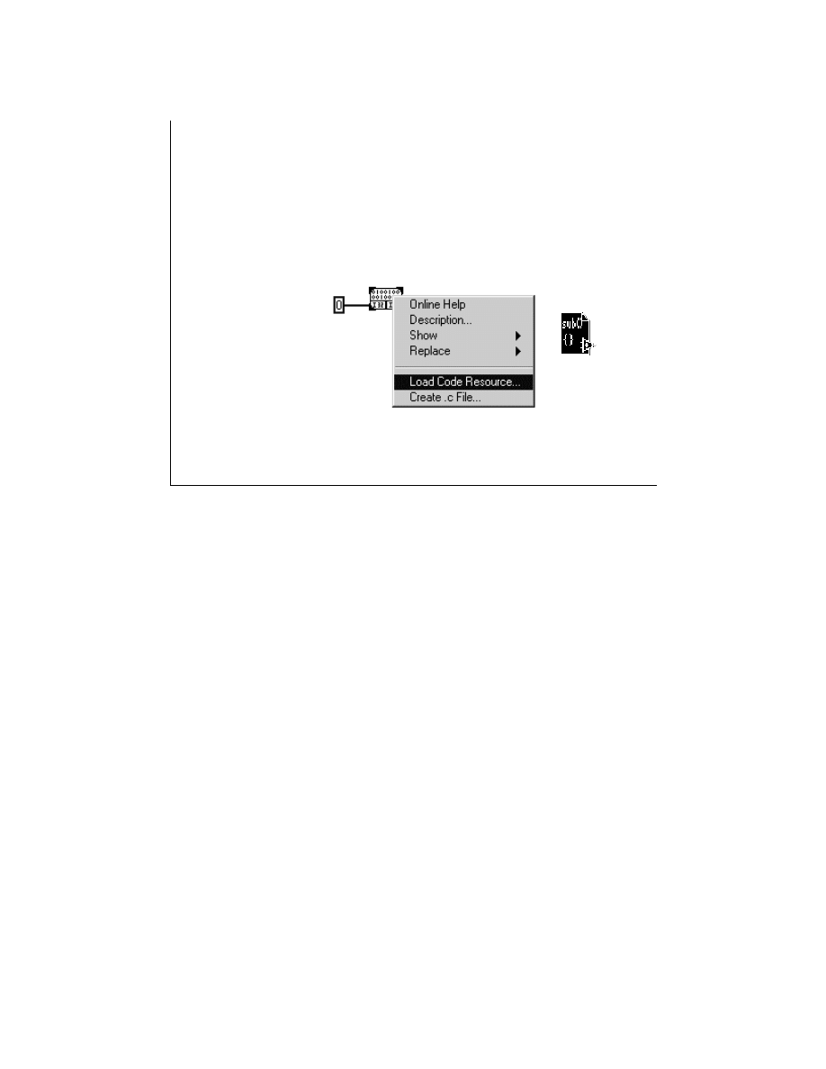
LabVIEW Advanced 1 Course Manual
253
© National Instruments Corporation
LV Adv I 253
Creating a CIN
7. Load the CIN Object Code
8. Save the VI
9. Run the VI
After modifying the code resource, load it by choosing Load
code resource... from the CIN pop-up menu. Select the
.lsb file created in the previous step
name.lsb
The Load Code Resource… command loads your code into LabVIEW memory and links the
code to the current block diagram. After saving your VI, the file containing the object code
need not be resident on the computer running LabVIEW for the VI to execute.

LabVIEW Advanced 1 Course Manual
254
© National Instruments Corporation
LV Adv I 254
Exercise 1-1
Students will observe when the CIN routines are called
during the operation of a VI.
Time to complete: 10 min.

LabVIEW Advanced 1 Course Manual
255
© National Instruments Corporation
LV Adv I 255
Summary Lesson 1
•
A code Interface Node (CIN) is a LabVIEW function
that links external code written in a
conventional
programming language, such as C, to LabVIEW.
•
The basic steps for creating a CIN are
:
1. Place the CIN on the block diagram.
2. Add the input and output terminals.
3. Wire all the input and output terminals.
4. Create the .c file.
5. Write the code of the external function.
6. Compile the code into a LabVIEW code resource
(.lsb) format.
7. Load the LabVIEW code resource into the CIN.
8. Run the VI.
9. Save the VI.

LabVIEW Advanced 1 Course Manual
256
© National Instruments Corporation
LV Adv I 256
Summary Lesson 1
•
The CIN code may contain eight interface routines-
CINInit, CINDispose, CINAbort, CINRun,
CINProperties, CINLoad, CINUnload and CINSave. The
only routine that is required is the CINRun routine,
which receives the input parameters and returns the
output parameters.

LabVIEW Advanced 1 Course Manual
257
© National Instruments Corporation
LV Adv I 257
Lesson 2
LabVIEW Managers
You Will Learn:
• About the LabVIEW manager functions.
• About the basic data types.
• About how to use pointers and handles.
• About some specific LabVIEW manager
functions.
Introduction
This lesson gives an overview of function libraries, called managers, that you
can access from a CIN.

LabVIEW Advanced 1 Course Manual
258
© National Instruments Corporation
LV Adv I 258
LabVIEW Manager Routines
• LabVIEW offers a set of libraries that can be
called from CINs.
• CINs built on top of the manager functions are
identical across platforms.
• These LabVIEW functions range from low level
byte manipulation to routines for sorting data
and managing memory.
• All LabVIEW manager routines are platform
independent.
LabVIEW includes a set of functions that you can call from CINs and external
subroutines. These functions, organized into libraries called managers, range
from low-level bit manipulation to routines for sorting data and managing
memory. All LabVIEW manager routines are platform independent. If you use
these routines, you can create external code modules that work on all platforms
that LabVIEW supports. In other words, you can compile the source code for
CINs and external subroutines written with the manager functions without
modifying the source code for all platforms that LabVIEW supports.
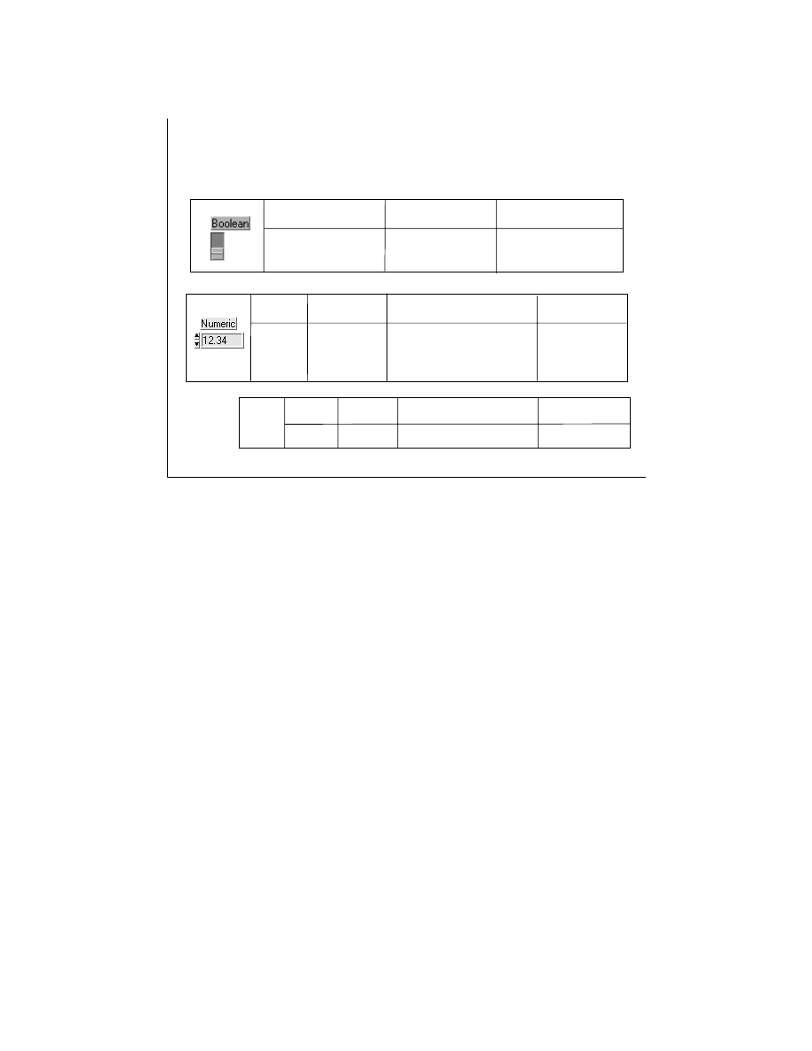
LabVIEW Advanced 1 Course Manual
259
© National Instruments Corporation
LV Adv I 259
LabVIEW Manager Data Types
Booleans
Numerics
Type
Code
Description
Representation
LabVIEW Boolean
LVBoolean 1/ 0 = T/F
Manager Boolean
Bool32 1/0 = T/F
Type
Size
Code
Description
Representation
Integer
8,16,32 bits
uInt8,uInt16,uInt32,int8,
unsigned and
int16, int32
signed
Floating
32,64,EXT bits
float32,float64,floatEXT
Complex
32,64,EXT bits
cmplx64,cmplx128,cmplxEXT
real/imaginary
Chars
Uchar 8 bits U8 Unsigned Char
Type
Size
Code Representation Description
a
A fundamental component of platform independence is the use of data types that do not
depend on the peculiarities of various compilers. The C language, for example, does not
define the size of an integer. Without an explicit definition of the size of each data type, it is
impossible to create code that works identically across multiple compilers.
Because the LabVIEW manager is intended for use with various C programming languages
on different platforms, it uses generic references to the data types. For example, if a routine
requires a 4-byte integer as a parameter, you define the parameter as an int32. The managers
define data types in terms of the fundamental data types for each compiler. Thus, on one
compiler, the managers might define an int32 as an int, while on another compiler, the
managers might define an int32 as a long int. When writing external code modules, use the
manager data types instead of the host computer data types, because your code will be more
portable and have fewer errors. The data types the manager uses also include specific
LabVIEW data types. In general, the LabVIEW data types are described with the prefix “LV”
as in LVBoolean, or “L” as in LStr, when necessary.
Manager functions return errors coded in the private data type MgErr. The different error
codes are defined in the header file
extcode.h
. For example, noErr and mFullErr refer to
no error found and memory full error, respectively.
The tables on this and the next slide describe some of the basic data types that LabVIEW and
the manager routines use.
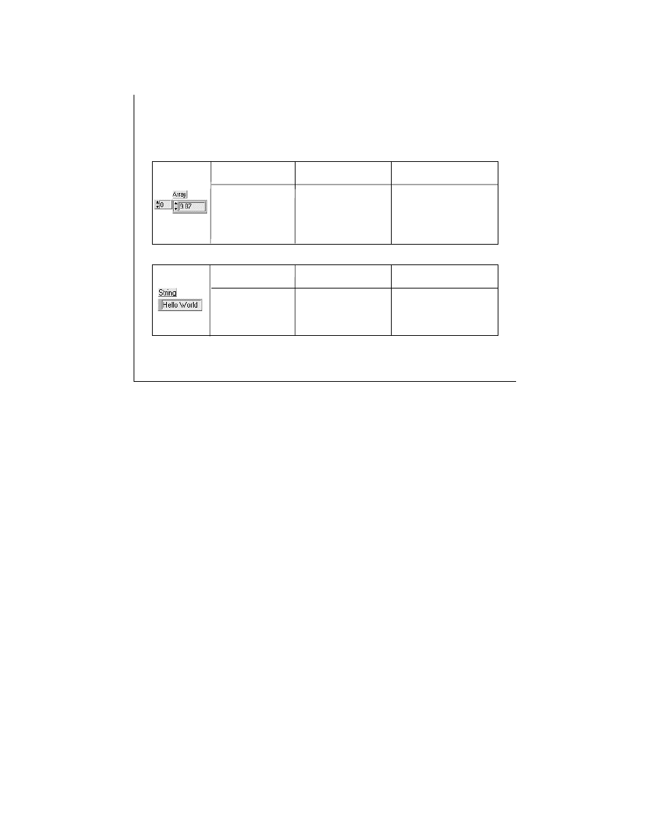
LabVIEW Advanced 1 Course Manual
260
© National Instruments Corporation
LV Adv I 260
LabVIEW Manager Data Types
Arrays
Strings
Type
Code
Description
Representation
Size: Integer typedef struct { Structure with the
int32 dimsize; size followed by the
elemType arg1[1]; elements.
} TD1;
Buffer: elemType
Type
Code
Description
Representation
C String
CStr
Ends with NULL
Pascal String
PStr
255 maximum
LabVIEW String LStr
First four bytes
indicates the length
Note : LabVIEW stores strings and Boolean arrays in memory as
one-dimensional arrays of unsigned 8-bit integers.
CINs work with two kinds of Booleans—those existing in LabVIEW block diagrams
(called LVBooleans) and those passing to and from manager routines (called Bool32).
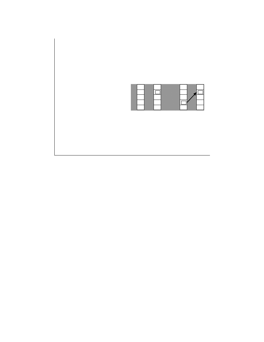
LabVIEW Advanced 1 Course Manual
261
© National Instruments Corporation
LV Adv I 261
Using Pointers and Handles
Manager functions may have parameters that are pointers or
handles. The manager can write a value to a preallocated
memory, or the manager routine reads a value from the memory
location, so you do not need to allocate memory for the return
value.
x
&x
ip:
x
ip:
int32 x; /* x is an int32 value */
int32 *ip; /* ip points to an int32
value */
ip = &x; /* ip points to x */
int32 space
A pointer is a variable that contains an address. A
handle is a pointer to a pointer.
Pointers reference data stored in a block of memory of a given size. Pointers are
nonrelocatable; this means that the LabVIEW memory manager cannot move the memory
block while that memory is allocated to a pointer.
A handle (a pointer to a pointer) solves this problem. A handle is the address of an address.
The second pointer, or address, is a master pointer, which the memory manager maintains. If
you reallocate a handle and it moves to another address, the memory manager updates the
master pointer to refer to the new address.
Some manager functions have parameters that are pointers or handles. In most cases, this
means that the manager writes a value to a preallocated block of memory. In some cases, the
function reads a value from the memory location, so you don’t need to allocate memory for the
return value.

LabVIEW Advanced 1 Course Manual
262
© National Instruments Corporation
LV Adv I 262
Using Pointers and Handles
A handle is a pointer to a pointer.
Correct:
foo (UHandle a) {
UHandle h; /*h is a space allocated for a handle*/
h = a; /* h has a value */
AZHandToHand (&h); /*Function copies data into correct new handle h*/
}
Incorrect:
foo (UHandle a) {
UHandle *h; /* h is a pointer to a space allocated for a handle*/
*h = a; /* h is undefined */
AZHandToHand (h) ; /*function writes to the incorrect address */
The examples on the slide above illustrate correct and incorrect ways to call a routine with a
handle parameter. The AZHandtoHand function copies the data referenced by the handle “h”
into a new handle and returns a pointer to the new handle in “h.” You can use this routine to
copy an existing handle into a new handle. The old handle remains allocated. This routine
writes over the pointer that is passed in, so you should maintain a copy of the original handle.

LabVIEW Advanced 1 Course Manual
263
© National Instruments Corporation
LV Adv I 263
LabVIEW Memory Manager
Applications use either
• Static Memory Allocation or
• Dynamic Memory Allocation
Memory Zones
• DS (Data Space Zone)
• AZ (Application Zone)
Note: The DS and AZ zones are currently only one zone,
but this may change in future releases of LabVIEW. Hence,
you should write your programs as if the two zones exist.
Most applications need routines for allocating and deallocating memory on request. The
LabVIEW memory manager functions can be used to allocate, manipulate, and release
memory.
Applications use two types of memory allocation: static and dynamic. With static
allocation, the compiler determines memory requirements when you create a program.
When you launch the program, LabVIEW creates memory for the known global memory
requirements of the applications. This memory remains allocated while the program runs.
However, static memory allocation cannot address the memory management requirements
of most real-world applications because most memory requirements cannot be determined
until run time.
With dynamic memory allocation, you reserve memory when you need it and free memory
when you are no longer using it. The LabVIEW memory manager supports two kinds of
dynamic memory allocation: one that uses pointers and another type that uses handles. In
other words, the LabVIEW memory manager supports dynamic memory allocation of both
nonrelocatable and relocatable blocks, using pointers and handles, respectively.
The memory manager defines generic handle and pointer data types as follows:
typedef uChar
*UPtr;
typedef uChar
**UHandle;

LabVIEW Advanced 1 Course Manual
264
© National Instruments Corporation
LV Adv I 264
LabVIEW Memory Manager
Functions
Memory Manager Functions
UHandle XXNewHandle(int32 size)
MgErr
XXDisposeHandle(UHandle h)
MgErr
XXSetHandleSize(UHandle h, int32 size)
int32
XXGetHandleSize(UHandle h)
Handle
XXHandToHand(UHandle *hp)
void
MoveBlock(UPtr *ps, Uptr * pd, int32 size)
Ptr
XxNewPtr(int32 size)
MgErr
XXDisposePtr(UPtr p)
Descriptions
Creates a handle to a relocatable block of size
bytes
Releases the memory referenced by h
Changes the memory referenced by h in size
bytes
Gets the memory referenced by h in bytes
Copies the data referenced by hp into a new hp
Moves size bytes from
address ps to address pd
Creates a pointer to a nonrelocatable block of
size bytes
Releases the memory referenced by p
LabVIEW’s memory manager interface has the ability to distinguish between two distinct
sections, which are called zones. LabVIEW uses the data space (DS) zone to hold VI
execution data, while the application zone (AZ) holds all other data. Most memory manager
functions have two corresponding routines, one for each of the two zones. Routines that
operate on the data space zone begin with DS and routines for the application zone begin
with AZ.
All data passed to and from a CIN are allocated in the DS zone (except for Paths, which use
AZ handles). You should use only file manager routines (not the AZ memory manager
routines) to manipulate Paths. This means that your CINs should use the DS memory
routines when working with parameters passed from the block diagram. The only exceptions
to this rule are handles created using the SizeHandle function, which allocates handles in
the application zone. If you pass one of these handles to a CIN, your CIN should use AZ
routines to work with the handle.
Some of the most common memory manager functions for memory allocation and
deallocation are listed in the table shown above. (XX can be either DS or AZ.)
Note: Currently, the two zones AZ and DS are actually one zone, but this may change in
future releases of LabVIEW. Hence, a CIN programmer should write programs as if the
two zones actually exist.

LabVIEW Advanced 1 Course Manual
265
© National Instruments Corporation
LV Adv I 265
LabVIEW Support Manager
Functions
Mathematical Operations
Descriptions
Double sin
(double x)
double
pow(double x, double y)
double
Sqrt (double x)
void
RandomGen(float64*xp)
Returns the sine of
x
Returns the value of
x
to the power of y
Returns the square root of
x
Generates a random number between 0 and 1 in
* xp
String Manipulations
Descriptions
int32 LStrLen(LStrPtr s)
uChar *LStrBuf(LStrPtr s)
Returns the length of s (s->cnt)
Returns the address of the data of s (s->str)
Note: You can use the string functions with LabVIEW, Pascal, or C Strings.
The support manager contains a collection of useful functions, such as string and array
manipulation, mathematical operations, sort functions, search functions, and so on. The
table on the slide above lists some commonly used support manager routines.
LabVIEW also supports a number of other mathematical functions defined in The C
Programming Language by Brian W. Kernighan and Dennis M. Ritchie. The support
manager also includes routines for complex and extended floating-point operations.

LabVIEW Advanced 1 Course Manual
266
© National Instruments Corporation
LV Adv I 266
LabVIEW Support Manager
Functions
Utility Functions
Descriptions
void QSort (UPtr array, int32 n, int32 elementSize,
procPtr CompareProcPtr)
int32 CompareProcPtr(UPtr a, UPtr b)
Sorts
n elements of array of any data type
with the QuickSort algorithm
Returns a negative, zero, or positive value if
a<b, a=b, or a>b, respectively
Timing Functions
Descriptions
CStr DateCString(ulnt32 secs, int32 fmt)
CStr TimeCString(ulnt32 secs, int32 fmt)
Returns a pointer to the date string of the secs
according to fmt
Returns a pointer to the time string of the secs
according to fmt
You can use the utility functions such as sort or search with arbitrary data types. However,
you must implement the comparison procedure.

LabVIEW Advanced 1 Course Manual
267
© National Instruments Corporation
LV Adv I 267
LabVIEW File Manager
Functions
Relative Paths: Location of a file or a directory relative to an arbitrary location
in the file system.
Absolute Paths: Location of a file or a directory starting at the top level of the file
system.
Platform
Absolute Path
Relative Path
to the Home Directory
Empty Path
absolute relative
PC
C:\HOME\LABVIEW\README
..\LABVIEW\README
" "
.
You can use functions in the file manager to create and manipulate files and directories.
This library supports basic file operations such as creating, opening, and closing files;
writing data to files, and reading data from files. You also can use the file manager
functions to create and manipulate directories or folders, including copying files. The file
functions use the LabVIEW data type for paths that create a platform-independent way of
specifying a file or directory path. You can translate the path to and from a specific host
platform’s conventional format for describing a path.
When working with files and directories, you need to identify the target of operation.
Operations such as copying and moving work on closed files; others such as reading and
writing work on open files. If a target is a closed file or a directory, you specify the target
using its pathname. If the target is an open file, you use the file descriptor. The file
descriptor is an identifier that the file manager associates with the file when it is opened.
When you close the file, the file manager disassociates the file descriptor from the file.
There are two types of paths: relative paths and absolute paths. A relative path describes
the location of a file or directory relative to an arbitrary location in the file system. An
absolute path describes the location of a file or a directory starting at the top level of the file
system. The table on the slide above describes some tags you can use (in place of a name) to
describe the path or its level from the current location. (Note that the “ ” characters indicate
an empty string.)
In LabVIEW, you specify the path using a special path data type. The exact structure of the
file path is private to the file manager. The path is also a dynamic structure (the same as
pointers and handles), and you use file manager routines to allocate and deallocate paths.

LabVIEW Advanced 1 Course Manual
268
© National Instruments Corporation
LV Adv I 268
LabVIEW File Manager
Functions
File Manager Functions
Descriptions
MgErr
MgErr
MgErr
MgErr
MgErr
MgErr
MgErr
FCreate(fdp, path, permissions, openMode,
denyMode, group)
FMOpen(fdp, path, openMode, denyMode)
FMClose(fd)
FMRead(fd, inCount, outCountp, buffer)
FMWrite(fd, inCount, outCountp, buffer)
FGetEOF(fd, sizep)
FMakePath(path, type, [volume, directory, name],
NULL)
FDisposePath(path)
Creates a file with Path
name
Opens a file with
path name
Closes the file with fd descriptor
Reads buffer from a file with
fd descriptor
Writes buffer to a file with fd descriptor
Returns the size of a file with
fd
descriptor
Creates a new path
Disposes of the specified path
Path
All operations performed on an open file use a file descriptor to identify the file. A file
descriptor has the special LabVIEW manager file data type. LabVIEW block diagrams use
file refnums to identify open files. To pass open file references into or out of a CIN, you
must use the manager functions to convert refnums to file descriptors because there is a
one-to-one correspondence.

LabVIEW Advanced 1 Course Manual
269
© National Instruments Corporation
LV Adv I 269
Exercise 2-1
Students will examine the syntax of
some memory manager functions.
Time to complete: 10 min.

LabVIEW Advanced 1 Course Manual
270
© National Instruments Corporation
LV Adv I 270
Exercise 2-2
Students will examine the syntax of
some support manager functions.
Time to complete: 10 min.

LabVIEW Advanced 1 Course Manual
271
© National Instruments Corporation
LV Adv I 271
Exercise 2-3
Students will examine the syntax of
some file manager functions.
Time to complete: 10 min.

LabVIEW Advanced 1 Course Manual
272
© National Instruments Corporation
LV Adv I 272
Summary Lesson 2
• The LabVIEW manager contains functions to manipulate data
within your CIN.
• You can use the memory manager to dynamically allocate,
manipulate, and release memory.
• The support manager contains generally useful functions for
mathematical operations and string or array manipulations.
You should use them instead of the routines that the C
compilers supply.
• You can use the functions in the file manager to manipulate
files, such as creating, opening, and writing to files.
• All manager routines are platform independent.

LabVIEW Advanced 1 Course Manual
273
© National Instruments Corporation
LV Adv I 273
Lesson 3
Passing Parameters
You Will Learn:
• About numerics and Booleans.
• About how to pass arrays and strings.
• About how to resize arrays and strings.
• About how to pass paths.
• About how to pass clusters.
Introduction
This lesson discusses passing parameters between LabVIEW diagrams
and CINs.
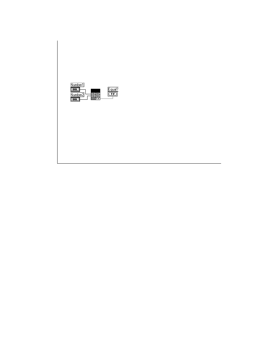
LabVIEW Advanced 1 Course Manual
274
© National Instruments Corporation
LV Adv I 274
Numerics and Booleans
/* Equal.c */
#include "extcode.h"
CIN MgErr CINRun(float64 *Number1,
float64 *Number2, LVBoolean *Equal);
CIN MgErr CINRun(float64 *Number1,
float64 *Number2, LVBoolean * equal){
if (*Number1 == *Number2)
*equal = LVTRUE;
else
*equal = LVFALSE;
return noErr;
}
Pointers to the data
Scalar parameters, such as numerics and Booleans, are passed by reference. The CINRun
routine receives pointers to the scalar input parameters and returns pointers to the scalar
output parameters.
LabVIEW stores Booleans in memory as 8-bit integers. If any bit of the integer is 1, the
Boolean is TRUE; otherwise, the Boolean is FALSE.
In LabVIEW 4.x and earlier, Booleans were stored as 16-bit integers. If the high bit of the
integer was 1, the Boolean was TRUE; otherwise the Boolean was FALSE.
For example, consider a CIN that compares two LabVIEW double-precision (DBL)
numbers, returning a LabVIEW Boolean TRUE if they are equal and a FALSE otherwise.
The block diagram and the
.c
file are shown on the slide above.

LabVIEW Advanced 1 Course Manual
275
© National Instruments Corporation
LV Adv I 275
Exercise 3-1
Students will pass numeric and Boolean arguments
between a CIN and a code resource.
Time to complete: 20 min.

LabVIEW Advanced 1 Course Manual
276
© National Instruments Corporation
LV Adv I 276
One-Dimensional Arrays
• 1D Numeric Arrays
Structures containing both the size and the data of the array.
•
1D Boolean Arrays
Structures containing both the size and the data of the array.
Boolean arrays are stored as one-dimensional array of 8-bit integers.
typedef struct {
int32 dimsize;
LVBoolean buf[1];
} **LVBooleanArrayHdl;
typedef struct {
int32 dimsize;
float32 buf[1];
} **LVArrayHdl;
dimSize = 3
buf[0] = 1.23
buf[1] = 4.56
buf[2] = 7.89
A 1D numeric array in LabVIEW is a structure containing both the data and the size of the
array. The size of the array is stored first in a 32-bit integer, followed by the data. The
figure above shows an example of a LabVIEW array of three numeric double-precision
(DBL) numbers with the corresponding array structure and memory offset.
LabVIEW Advanced 1 Course Manual
277
© National Instruments Corporation
LV Adv I 277
Strings
Structures containing both the size and the data of
the string.
typedef struct {
int32 cnt; /* number of bytes that follow */
uChar str[1]; /* cnt bytes */
} LStr, *LStrPtr, **LStrHandle;
Hello
String
0 4
0 5
0 6
0 7
0 8
0 0
str[0] = H
str[1] = e
str[2] = l
str[3] = l
str[4] = o
cnt = 5
Like arrays, LabVIEW strings are structures pointed by handles. The handle to the string is
passed as the argument between the block diagram and the code resource. The string
structure contains both the data and the string length. The string length is stored first in a
32-bit integer, followed by the data.
The header file
extcode.h
defines the following structure for LabVIEW strings:
typedef struct {
int32 cnt;
/* number of bytes that follow */
uChar str[1];
/* cnt bytes */
} LStr, *LStrPtr, **LStrHandle;
The support manager has functions to access both components. To find the string length or
number of characters in the buffer, you use the LStrLen function. To find the buffer
address, you can call the LStrBuf function.
The example on the slide above shows a LabVIEW string with five characters and its
memory offset representation.
LabVIEW Advanced 1 Course Manual
278
© National Instruments Corporation
LV Adv I 278
Multidimensional Arrays
Structures containing both the sizes (elements
per dimension) and the data of the array.
5
6
1
2
3
4
0
0
2D Array
typedef struct {
int32 dimSizes[2]; /* 2 dimensions */
int16 data[1];
/* elements */
} LV2DArray;
typedef LV2DArray **LV2DArrayHdl;
1 6
1 8
0 4
0 8
1 0
1 2
14
0 0
data [1][2]
data [1][1]
data [1][0]
data [0][2]
data [0][1]
data [0][0]
dimSizes[0] = 2
dimSizes[1] = 3
LabVIEW stores N-dimensional arrays much like 1D arrays. However, the handle begins with N
4-byte values that describe the number of values stored in a given dimension. The example
above shows a two-dimensional (2D) array of integers with two rows and three columns. The
code fragment that defines the structure is also shown.

LabVIEW Advanced 1 Course Manual
279
© National Instruments Corporation
LV Adv I 279
Exercise 3-2
Students will observe how LabVIEW passes a
1D numeric array to a code resource.
Time to complete: 10 min.

LabVIEW Advanced 1 Course Manual
280
© National Instruments Corporation
LV Adv I 280
Exercise 3-3
Students will observe and/or write code that shows
how LabVIEW passes a Boolean array to a CIN.
Time to complete: 15 min.

LabVIEW Advanced 1 Course Manual
281
© National Instruments Corporation
LV Adv I 281
Exercise 3-4
Students will observe and/or write code that shows
how LabVIEW passes a string to a CIN.
Time to complete: 15 min.

LabVIEW Advanced 1 Course Manual
282
© National Instruments Corporation
LV Adv I 282
Exercise 3-5
Students will observe or write code that shows how
LabVIEW passes a multidimensional array to a CIN.
Time to complete: 10 min.

LabVIEW Advanced 1 Course Manual
283
© National Instruments Corporation
LV Adv I 283
Resizing Arrays and Strings
typeCode
uB
uW
uL
iB
iW
iL
fS
fD
fX
cS
cD
cX
LabVIEW Data Type
Unsigned Byte
U8
Unsigned Word U16
Unsigned Long
U32
Integer Byte
I8
Integer Word
I16
Integer Long
I32
Floating Single
SGL
Floating Double DBL
Floating Extended EXT
Complex Single CGL
Complex Double CBL
Complex Extended CXT
• SetCINArraySize(UHandle dataH, int32 paramNum,
int32 newNumElements)
• NumericArrayResize(int32 typeCode, int32 dimension,
(UHandle *) dataH, int32 newNumElements)
Note:
Resizing the
handle does not update
the dimension field
(number of elements
per dimension) of array
and string handles.
Note:
Only the
NumericArrayResize
function can be used to
resize LabVIEW strings
because they are
considered 1D arrays of
characters (bytes).
Sometimes output variables require you to modify the size of the block of memory needed
by the array or the string within the CIN code.
The SetCINArrayResize and the NumericArrayResize functions resize arrays and strings.
Note: The paramNum is the position of the handle parameter in the CIN argument list, where
the left parameter has the position 0. For example, in the code: CINRun(int32 var1,
LVArrayHdl var2, LVBoolean var3, LVArrayHdl var4); the parameter number for the first
array, var2, is 1. For the second array, var4, the parameter number is 3.
Both the SetCINArraySize and NumericArrayResize functions define the exact amount of
memory required for the new array structure, but the new array size is undefined. If you
successfully resize the array, either with the SetCINArraySize or NumericArrayResize, you
need to update the dimension field with the number of elements in the array.
Use the SetCINArraySize function to resize arrays returned by the CIN. The function
resizes a data handle based on the data structure of an argument that you pass to the CIN.
Although you specify the new number of elements and the parameter number, the function
does not update the dimension field in the array; you must do that separately.
You can resize numeric arrays more easily with NumericArrayResize. This function resizes
a data handle that refers to a numeric array. Although you specify the total new number of
elements, the type of numeric elements, and dimension(s), the function does not set the
dimension field in the array; you must set that field in your code. DimSize contains the
number of elements in the array.

LabVIEW Advanced 1 Course Manual
284
© National Instruments Corporation
LV Adv I 284
Resizing Arrays and Strings
#include "extcode.h"
typedef struct {
int32 dimSizes[2];
float64 arg1[1];
} TD1;
typedef TD1 **TD1Hdl;
#define
ParamNum 1
CIN MgErr CINRun(TD1Hdl Array, TD1Hdl New_Array);
CIN MgErr CINRun(TD1Hdl Array, TD1Hdl New_Array) {
int32 i, j, nrows, ncols;
float64 *fElmnt, *rElmnt;
MgErr mgError = noErr;
nrows = (*Array)->dimSizes[0];
ncols = (*Array)->dimSizes[1];
if(!(fElmnt = (*Array)->arg1)){
mgError = mFullErr;
goto out;
}
N e w _ A r r a y
A r r a y
Array
New_Array
Now consider a CIN similar to the example where the 2D array is transposed. The result is
passed in a new array with the same characteristics as the input array. The block diagram
and the source file for this transpose CIN is shown on this and the next slide.
Notice that LabVIEW passes the handle that points to the input array. The code resource
dynamically defines a new array structure and its size, based on information from the input
array handle. Then the source code performs the transposition.

LabVIEW Advanced 1 Course Manual
285
© National Instruments Corporation
LV Adv I 285
Resizing Arrays and Strings
/* Allocate memory for transposed array */
if (mgError = SetCINArraySize((UHandle) New_Array, ParamNum, (nrows
*ncols)))
goto out;
rElmnt = (*New_Array)->arg1;
/* Perform the transposition */
for (i=0; i< nrows ; i++)
for (j=0; j < ncols ; j++)
rElmnt[i + nrows * j] = fElmnt[i * ncols + j];
/* Transposed array has rows and columns interchanged */
(*New_Array)->dimSizes[0] = ncols;
(*New_Array)->dimSizes[1] = nrows;
out:
return mgError;
}

LabVIEW Advanced 1 Course Manual
286
© National Instruments Corporation
LV Adv I 286
Exercise 3-6
Students will examine and write code that
shows how to resize an array handle
within a code resource.
Time to complete: 15 min.

LabVIEW Advanced 1 Course Manual
287
© National Instruments Corporation
LV Adv I 287
Exercise 3-7
Students will examine and write code that shows how to
resize an string handle within a code resource.
Time to complete: 15 min.

LabVIEW Advanced 1 Course Manual
288
© National Instruments Corporation
LV Adv I 288
Paths
• Paths - Dynamic data structures
typedef Private *Path;
/* PathStr.c -> Converts a Path into a LabVIEW string
* parameters: input: pathIn-> handle to a path
* stringOut-> handle to a LabVIEW string */
#include "extcode.h"
CIN MgErr CINRun(Path pathIn, LStrHandle stringOut);
CIN MgErr CINRun(Path pathIn, LStrHandle stringOut) {
MgErr
cinErr = noErr;
cinErr = FPathToDSString(pathIn,&stringOut) /* path to a string */
return cinErr;
}
Paths are dynamic data structures that LabVIEW passes the same way it passes arrays. The
data for paths belong to the application zone handle.
Usually, you do not need to know the exact structure of a path. As an example, consider a CIN
that uses one of the file manager functions to convert a LabVIEW path into a LabVIEW string,
as shown on the slide above.
LabVIEW Advanced 1 Course Manual
289
© National Instruments Corporation
LV Adv I 289
Clusters
• Clusters - Structures containing different elements.
Numerics and Booleans are stored directly in the
cluster structure. Arrays and strings are stored
indirectly.
1.00
Number
Boolean
String
0
0
Array
Cluster
typedef struct {
float32 sglNumber;
LVBoolean booleanSw;
LVStrHdl lvString;
LVArrayHd intArray
} Cluster;
A cluster stores elements of different data types according to cluster order. Numerics and
Booleans are stored directly in the cluster structure, while arrays and strings are stored
indirectly. The cluster structure contains the handle that points to the memory block that the
arrays or strings use.
For example, consider a cluster containing a double-precision (DBL) number, a Boolean, a
string, and an array of integer numbers. The diagram above shows the cluster with its order.
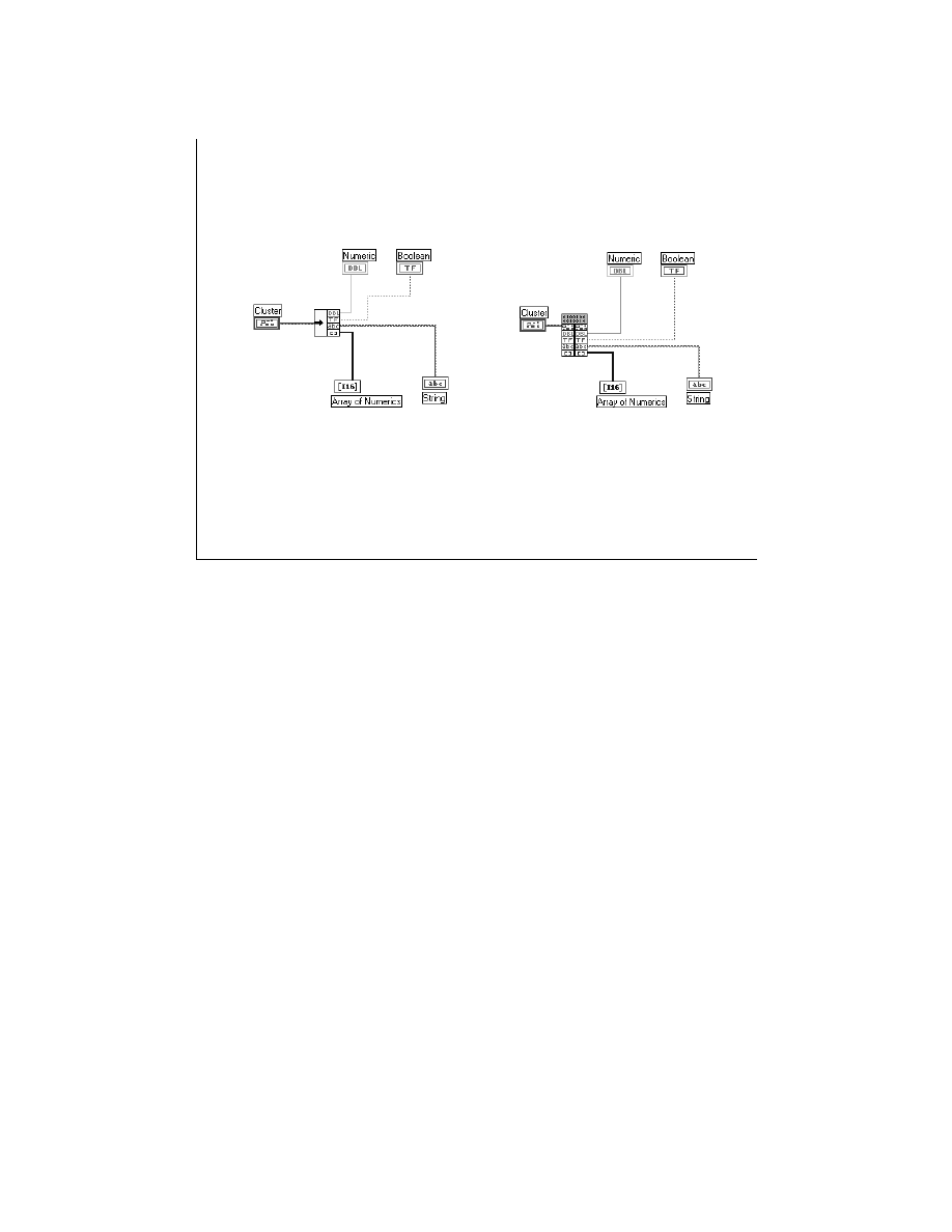
LabVIEW Advanced 1 Course Manual
290
© National Instruments Corporation
LV Adv I 290
Clusters
Unbundle
CIN Unbundles Cluster
The slide above shows the Unbundle function with the cluster order. If a CIN unbundles the
elements of the cluster, the block diagram may resemble the diagram shown above.

LabVIEW Advanced 1 Course Manual
291
© National Instruments Corporation
LV Adv I 291
Clusters
#include "extcode.h”
#define DIMENSION 1L
typedef struct {
int32 dimSize;
int16 buf[1];
} LVArray;
typedef LVArray **LVArrayHdl;
typedef struct {
float64 dblNumber;
LVBoolean booleanSw;
LStrHandle lvString;
LVArrayHdl intArray;
} Cluster;
CIN MgErr CINRun(Cluster *clusterIn, float64 *numberOut, LVBoolean
*booleanOut, LStrHandle stringOut, LVArrayHdl arrayOut);
The source code for a CIN that unbundles the elements of the cluster is shown on this and
the next slide.
Notice that the LabVIEW manager functions allocate memory for the string and array
outputs (NumericArrayResize) to get the length of the string in the cluster and to set the
length of the string output (LstrLden). The functions also get the data buffer address of the
strings (LstrBuf) and copy bytes from the cluster elements to the array and string outputs
(MoveBlock).

LabVIEW Advanced 1 Course Manual
292
© National Instruments Corporation
LV Adv I 292
Clusters
CIN MgErr CINRun(Cluster *clusterIn, float64 *numberOut, LVBoolean
*booleanOut, LStrHandle stringOut, LVArrayHdl arrayOut) {
int32 arraySize, stringLength;
MgErr
err = noErr;
*numberOut = clusterIn ->dblNumber;
/* get/set the number */
*booleanOut = clusterIn ->booleanSw;
/* get/set the boolean */
stringLength = LStrLen(*(clusterIn ->lvString)); /* get the length */
arraySize = (*(clusterIn ->intArray))->dimSize;
/* get the size */
/* set StringOut memory */
if(err = NumericArrayResize(uB,DIMENSION,(UHandle *)&stringOut,
stringLength)) goto out;
/* set ArrayOut memory */
if(err = NumericArrayResize(iW, DIMENSION, (UHandle *)&arrayOut,
arraySize)) goto out;
LStrLen(*stringOut) = stringLength;
/* update the string length */
(*arrayOut)->dimSize = arraySize;
/* update the array size */
/* copy the string buffer */
MoveBlock(LStrBuf(*(clusterIn->lvString)), LStrBuf(*stringOut),
stringLength);
/* copy the array buffer */
MoveBlock((*(clusterIn->intArray))->buf, (*arrayOut)->buf, arraySize * sizeof(int16));
out: return err;
}

LabVIEW Advanced 1 Course Manual
293
© National Instruments Corporation
LV Adv I 293
Summary Lesson 3
• LabVIEW passes numeric and Boolean arguments
and clusters with numeric or Boolean data types to
the code resource by reference.
• Arrays and strings are stored as relocatable objects
pointed by handles, and the handle structure is
passed as an argument.
• Whenever you output an array, string, or cluster
handle, be sure to first allocate the memory for the
handle. Also, remember to update the dimension
field in every output array or string structure.

LabVIEW Advanced 1 Course Manual
294
© National Instruments Corporation
LV Adv I 294
Lesson 4
Advanced CIN Topics
You Will Learn:
• About shared external subroutines.
• About the advantages of using external
subroutines.
• About how to create and call external
subroutines.
• About multithreading and CINs.
• About how globals work within CINs.
• About how to call WIN32 DLLs from CINs.
Introduction
This lesson discusses topics that are needed only in advanced applications using
CINs in LabVIEW.
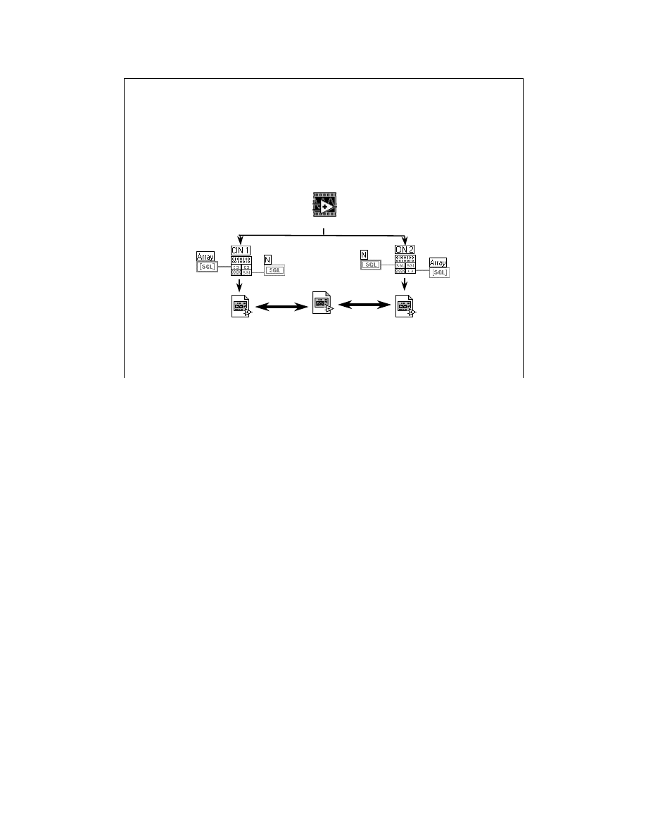
LabVIEW Advanced 1 Course Manual
295
© National Instruments Corporation
LV Adv I 295
External Subroutines
An external subroutine is a function that you can call
from CINs and other external subroutines. External
subroutines are stored in their own separate files.
LabVIEW
code 2.lsb
External
Subroutine
code 1.lsb
An external subroutine is a function you can call from CINs or other external subroutines.
External subroutines differ from CINs in that LabVIEW diagrams do not call them directly.
Instead, an external subroutine is a function that CINs or other external subroutines call.
External subroutines are stored in separate files, not in VIs. When you load a VI that contains a
CIN, LabVIEW determines whether the CIN references external subroutines. If it does,
LabVIEW loads the subroutine into memory and modifies the calling code so that it can call the
subroutine. When you close a VI containing a CIN with an external subroutine reference,
LabVIEW unloads the external subroutine.

LabVIEW Advanced 1 Course Manual
296
© National Instruments Corporation
LV Adv I 296
Advantages of Using
External Subroutines
• Easier to maintain
• Reduce memory requirements
• Shared code between CINs
• Ready-to-use analysis external
subroutines
• It is your responsibility to handle
error checking and pass
parameters correctly when
calling an analysis or any other
external subroutine
There are several advantages to external subroutines.
•
A single subroutine is easier to maintain, because you modify only a single file to affect all
calls on the subroutine.
•
A single subroutine can reduce memory requirements. Only a single instance of the code is
in memory, regardless of the number of calls to the subroutine.
•
An external subroutine can maintain information that several external code modules use.
The external subroutine can store data in global variables that multiple code resources can
access.
External analysis subroutines do not check for errors. It is your responsibility to handle error
checking and pass parameters correctly. Failure to do so may result in erroneous results or
system crashes. Typically, a VI passes parameters to a CIN, which checks for errors. If the code
detects any invalid parameters, the CIN returns the proper error code to the calling VI. If there
are no errors, the CIN invokes the external subroutine.
External subroutines are separate pieces of code needed each time you load a CIN that calls the
subroutine. When LabVIEW loads the VI containing a CIN that calls a given external
subroutine, it searches for the subroutine as a separate file, loads its code, and modifies the
calling CIN to point to the memory location of the external subroutine code. When you close the
VI, LabVIEW unloads the external routine as a different file.
Note: One way to ensure that LabVIEW can find the external subroutines is to place them in
directories that you defined in the search path section of the LabVIEW Preferences window
(Edit Menu). If you are using the Application Builder to build the executable, be sure that the
external subroutine is in the same directory as the application executable.

LabVIEW Advanced 1 Course Manual
297
© National Instruments Corporation
LV Adv I 297
Creating an External Subroutine
The external subroutine code must have an entry
point
LVSBMain().
The type of the subroutine is
LVSB
(LabVIEW subroutine).
#include "extcode.h"
/* prototype */
int32 LVSBMain(int32 *n);
/* subroutine */
int32 LVSBMain(int32 *n) {
int32 i, fact;
fact = 1L;
for (i=1; i<*n+1; i++)
fact *= i;
return fact;
}
Fact.c
External subroutines differ from standard CINs in that LabVIEW calls CINs and only your code calls
external subroutines. An external subroutine is a code that doesn’t need the eight CIN subroutines
(CINInit, CINDispose, CINAbort, CINRun, CINLoad, CINUnload, CINProperties). For an external
subroutine, you need only one entry point—LVSBMain. It is similar to the CINRun routine.
For example, consider a shared external subroutine that calculates the factorial number of an integer. The
shared external subroutine source code is shown in the slide above.
Note: The external subroutine can have an arbitrary number of parameters, and each parameter can
be of arbitrary data type. Notice that you can declare any return data type because only your code calls
the subroutine.
You call external subroutines the same way that you call standard C subroutines. However, you do not
compile the code for the external subroutine with the code of the calling subroutine. Instead, you compile
the code resource without the subroutine code.
For example,
int32 Fact(int32 *N);
defines the prototype of the previous factorial external subroutine. Any CIN can call this external
subroutine with the statement:
var1 = Fact(*var2);
where
var1
is an integer and
var2
is a pointer to an integer value.
However, the external subroutine code is not compiled with the CIN code. Instead, the CIN code is
prepared for LabVIEW with the reference to an external subroutine. When LabVIEW loads the CIN,
LabVIEW also loads the external subroutine based on the information that indicates the calling code
references to a given external subroutine. LabVIEW also modifies the calling code to ensure that it
correctly passes control to the subroutine.

LabVIEW Advanced 1 Course Manual
298
© National Instruments Corporation
LV Adv I 298
Compiling an External Subroutine
name = Fact
type = LVSB
!include $(CINTOOLSDIR)\ntlvsb.mak
Fact.lvm
You compile an external subroutine in almost the same way you compile a CIN. The external
subroutine should use the extension
.lsb
(for example,
fact.lsb
). The following
descriptions show how to compile a shared external subroutine using the Visual C++ compiler.
Windows 95/NT/98—Visual C++
Create one makefile with the same characteristics as a standard CIN. However, specify a code
type of LVSB (external subroutine) instead of the CIN type used for code resources.
type = LVSB
You build the external routine the same way you build a CIN (see Lesson 1, CIN Basics). For
this example, the makefile for the Visual C++ compiler is:
name = Fact
type = LVSB
!include $(CINTOOLSDIR)\ntlvsb.mak

LabVIEW Advanced 1 Course Manual
299
© National Instruments Corporation
LV Adv I 299
Calling an External Subroutine
Notice that the directive subrNames is used to
identify the subroutine the CIN references.
#include “extcode.h”
extern int32 Fact(int32 *n);
CIN MgErr CINRun(int32 *n);
CIN MgErr CINRun(int32 *n) {
*n = Fact(*n);
/*external call */
return noErr;
}
Fact calling code
name = FactCall
type = CIN
subrNames = Fact
!include $(CINTOOLSDIR)\ntlvsb.mak
Calling code .lvm file
* To use Visual C++ IDE
add lvsb.obj instead of cin.obj
Consider a CIN that calls the external subroutine defined earlier that calculates the factorial number of an
integer variable. The source code of the calling CIN is shown in the slide above.
When you call the external subroutine, you do not use the function name LVSBMain to call the function,
but you use the name you gave the external subroutine. In this case, the name of the function is Fact.
You should also declare the function prototype with the keyword
extern
so that the compiler will
compile the CIN, even though the subroutine is not present.
Windows 95/NT/98—Visual C++ Compiler
Create one makefile with the same characteristics as a standard CIN. The only difference is that you use
the optional
subrNames
directive to identify the subroutines that the CIN references. Specifically, if
your code calls two external subroutines,
A
and
B
, you must add the directive
subrNames = A B
prior to the
!include
statement. For example, consider the makefile that links your calling code with
the shared external subroutine
Fact.lsb
. The file list for the Visual C++ compiler is shown below.
name=FactCall
type=CIN
subrNames = Fact
!include <$(CINTOOLSDIR)\ntlvsb.mak>
You can create the
FactCall.lsb
CIN using the following command for Visual C++:
C:\LABVIEW\CINCLASS\FACTCALL>nmake /f factcall.lvm
After you create the code resource, you can load it with the CIN using the pop-up menu.
Note: If you are using the Visual C IDE, follow the steps described in Steps for Creating a CIN
section of Lesson 1, CIN Basics, with the exception of adding lvsb.obj instead of cin.obj to your
project.

LabVIEW Advanced 1 Course Manual
300
© National Instruments Corporation
LV Adv I 300
Exercise 4-1
Students will examine code that creates
and calls an external routine.
Time to complete: 15 min.
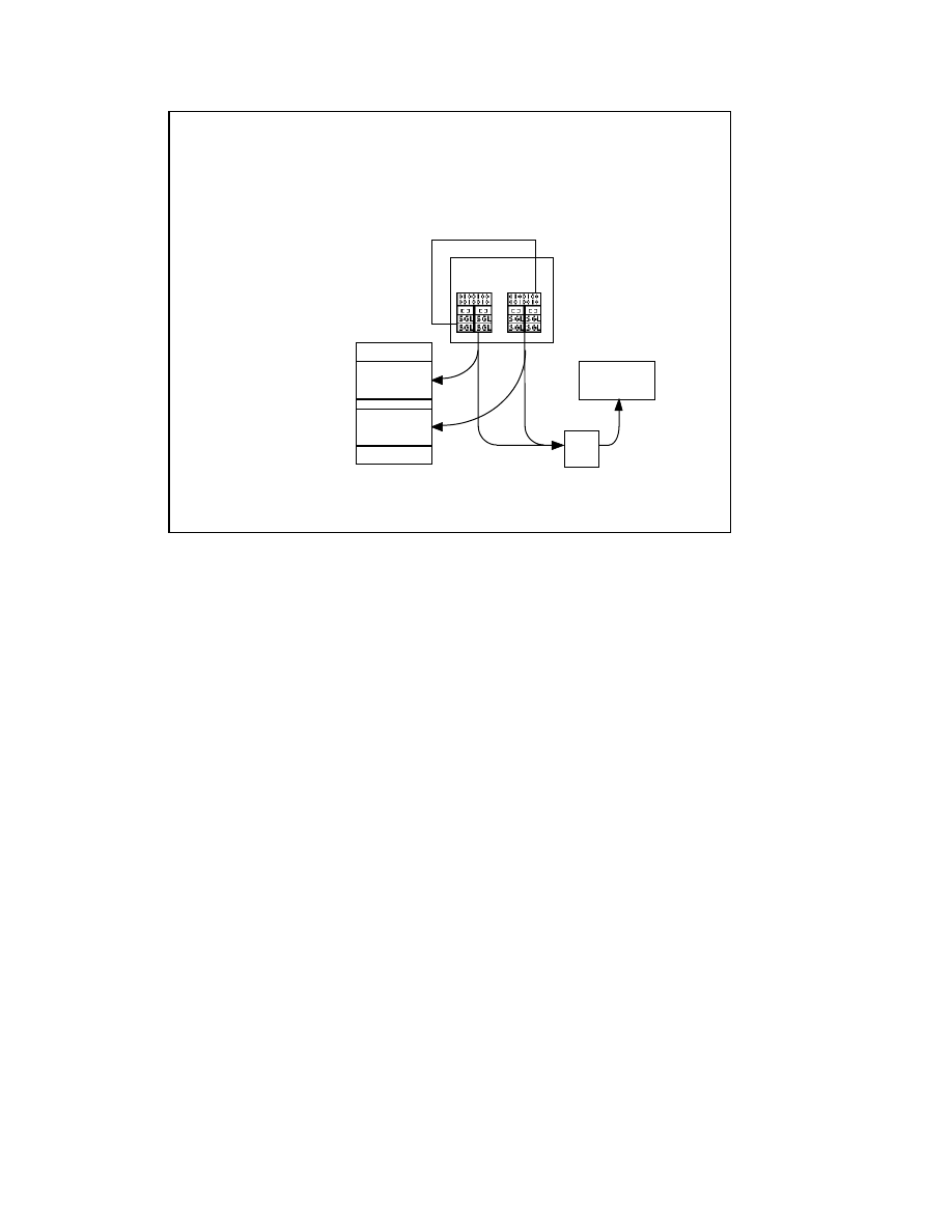
LabVIEW Advanced 1 Course Manual
301
© National Instruments Corporation
When you declare global or static local data within a CIN code resource, LabVIEW allocates
storage for that data and maintains your globals across calls to various routines. LabVIEW
features two methods to maintain the global variables—code globals or data space globals.
When you design your code, decide which method is appropriate to use. (If you have only
one CIN and the VI is not reentrant, it doesn’t matter which method you choose.)
When using code globals, calling the same code resource from multiple nodes or different
reentrant VIs affects the same set of globals. On the other hand, if you use CIN data space
globals, each CIN that calls the same code resource and each VI (if the VI is reentrant) can
have its own set of globals. When you allocate a code global in a CIN, LabVIEW creates
storage for only one instance of the global, regardless of the number of references to the
same code resource or external subroutine in memory.
LV Adv I 301
Using Global Variables
LabVIEW offers two methods to maintain global
variables within CINs.
• Code globals
• Data space globals
4-bytes CIN
Data Space
4-bytes CIN
Data Space
VI Data Space
(data space globals)
Call 1
Call 2
VI Diagram
VI Front Panel
code resource
global storage
(code globals)

LabVIEW Advanced 1 Course Manual
302
© National Instruments Corporation
LV Adv I 302
Using Code Globals
• When you use code globals, calling the same code
resource from multiple nodes or different reentrant
VIs affects the same set of globals.
• The variables can be initialized in CINLoad. If the
variables are pointers or handles, you can allocate
the memory in CINLoad and deallocate it in
CINUnload.
Code Globals
When you use code global variables, the variables are initialized in CINLoad. This is because
LabVIEW calls the CINLoad routine only once when the resource is first loaded into memory,
regardless of the number of data spaces and the number of references to that code resource. After the
last reference for that code resource is removed from memory (when closing the VI), LabVIEW calls
the CINUnload allocated in CINLoad. If the variables are pointers or handles, you can allocate the
memory in CINLoad and deallocate it in CINUnload.

LabVIEW Advanced 1 Course Manual
303
© National Instruments Corporation
LV Adv I 303
Data Space Globals
• When you use CIN data space globals, each CIN that
calls the same code resource and each VI (if the VI
is reentrant) can have its own set of globals.
• The variables can be initialized in CINInit. If the
variables are pointers or handles, you can allocate
the memory in CINInit and deallocate it in
CINDispose.
In some cases, such as when the VI that contains the CIN is reentrant, you may want a separate
reference to the CIN global variables for each use of the VI. LabVIEW allocates a CIN data
space for each instance of this type of global (called a CIN data space global). You should
initialize the CIN data space globals in CINInit because LabVIEW calls the CINInit function for
each use of the CIN or the surrounding VI (if the VI is reentrant). Remember that LabVIEW
also calls CINDispose for each CINInit call. Within CINInit, CINDispose, CINAbort, and
CINRun, you can retrieve or set the value of the CIN data space for the current instance of the
global with the following functions:
int32 GetDSStorage(void);
This routine returns the value of the 4-byte quantity in the CIN data space that LabVIEW
allocates for each use of the CIN or the surrounding VI (if the VI is reentrant).
int32 SetDSStorage(int32 NewVal);
This routine sets the value of the 4-byte quantity in the CIN data space that LabVIEW allocates
for each use of the CIN or the surrounding VI (if the VI is reentrant). It also returns the old value
of the 4-byte quantity in that CIN data space.

LabVIEW Advanced 1 Course Manual
304
© National Instruments Corporation
LV Adv I 304
Exercise 4-2
Students will examine code that shows
how a CIN uses code global variables.
Time to complete: 10 min.

LabVIEW Advanced 1 Course Manual
305
© National Instruments Corporation
LV Adv I 305
Exercise 4-3
Students will examine code that shows how
LabVIEW uses a CIN data space global variable.
Time to complete: 10 min.
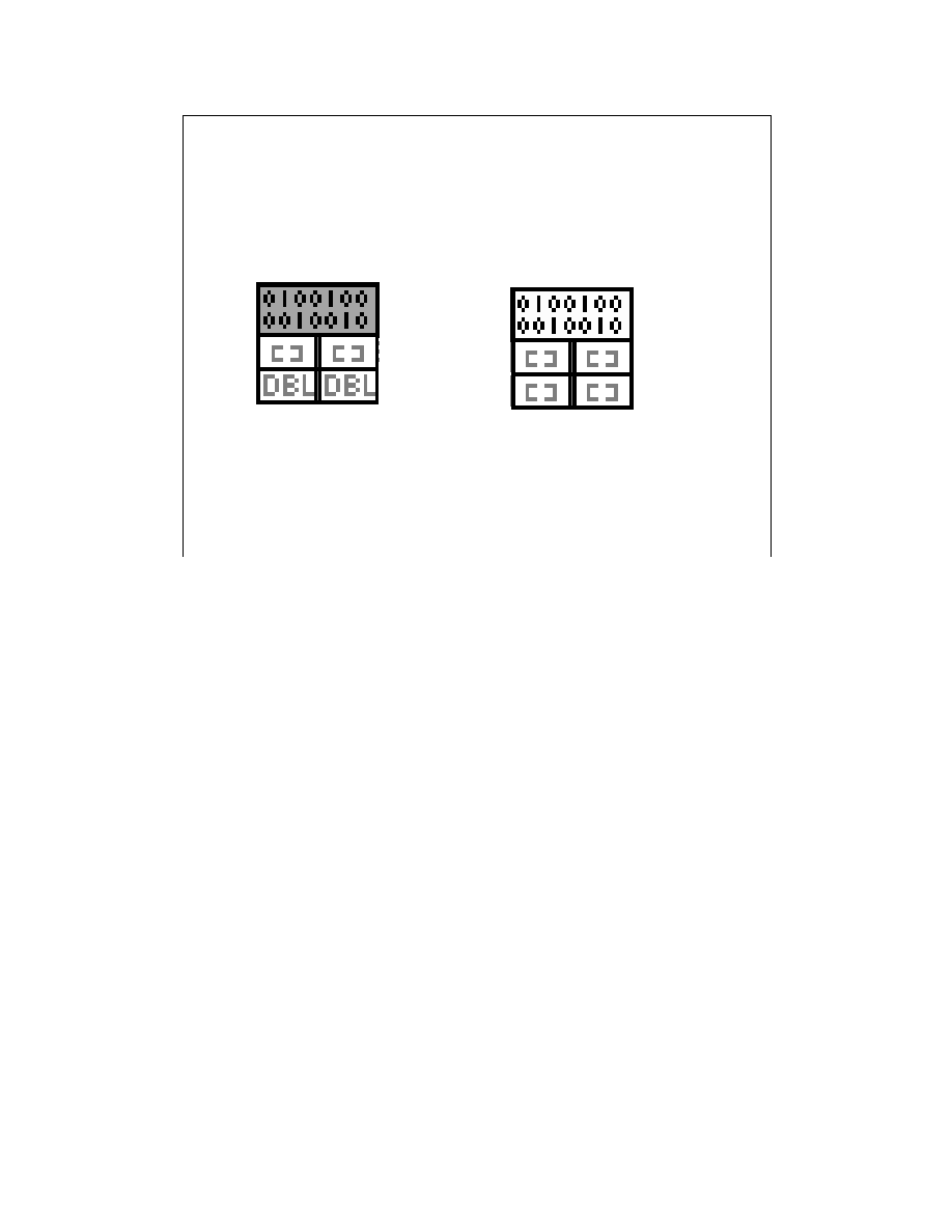
LabVIEW Advanced 1 Course Manual
306
© National Instruments Corporation
LV Adv I 306
Multithreading in LV 5.0
CIN marked
pale yellow
is thread
safe
CIN marked
ORANGE
is thread
unsafe
In Module 1, we discussed how LabVIEW handles multithreading and the various
execution systems. In this section, we will discuss how multithreading affect CINs and their
execution. It is important to know that CINs are synchronous. So, in a multithreaded
environment, this means that they execute to completion, and the thread in which they run
is monopolized by that task until it completes. If your CIN is thread unsafe, the execution
of your multithreaded VI is interrupted to switch to the user interface thread, run the CIN or
shared library, then switch back. This context switch time can be significant, especially if
the CIN or DLL is called often.
By default, CINs written before LabVIEW 5.0 run in a single thread, the user interface
thread. A CIN node that is orange in color indicates that the CIN is thread-unsafe, and
hence will not be able to take advantage of LabVIEW’s multithreaded capabilities. After
making certain changes to your source code, you can mark the CIN as thread-safe. The CIN
node then appears pale yellow in color. Now your CIN is safe to run in multiple threads.

LabVIEW Advanced 1 Course Manual
307
© National Instruments Corporation
LV Adv I 307
Multithreading in LV 5.0
CIN MgErr CINProperties(int32 prop, void *data)
{
switch (prop) {
case kCINIsReentrant:
*(Bool32 *) data = TRUE;
return noErr;
break;
}
return mgNotSupoorted;
}
To mark your CIN source file thread-safe:
Add this function to your “C” file:
The inclusion of the CINProperties function allows you to set whether LabVIEW treats
your CIN as thread-safe or not. When you open a new CIN node from the Functions »
Advanced menu, it appears orange in color as discussed in the earlier slide. If you specify
the above function in the source file, compile the CIN, and load the
.lsb
file, the CIN
node is converted to pale yellow, indicating that your CIN is thread-safe. If your CIN is
thread-safe or reentrant (execute in multiple threads), more than one execution thread can
call the CIN at the same time. Whether the CIN is actually thread-safe depends entirely on
your code. Next, we will discuss some of the guidelines for deciding whether a CIN or a
DLL is thread-safe.

LabVIEW Advanced 1 Course Manual
308
© National Instruments Corporation
LV Adv I 308
Writing Thread-Safe CINs
Your CIN /shared library
•
Does not have any global storage data (global variables, files
on disk, etc).
• AND it does not access any hardware (register-level programming)
•AND it does not call any functions/shared libraries/drivers that are thread-
unsafe
Your CIN/shared library protects
• Access to global resources with semaphores or mutexes
OR
OR
Your CIN
• Is only called from one nonreentrant VI.
• AND it does not have access to any global resources from
CINInit, CINAbort, etc., procedures
CINs are thread-safe if:
For detailed implementation on how to write thread-safe CINs, please refer to your favorite C
programming reference. Some of the guidelines for writing thread-safe CINs are mentioned on
the slide above. If you read or write a global or static variable or call a nonreentrant function
within your CINs, keep the execution of those CINs in a single thread. Even though a CIN is
marked reentrant, the CIN functions other than CINRun are called from the user interface
thread. Thus, for example, CINInit and CINDispose are never called from two different threads
at the same time, but CINRun may be running when the user interface thread is calling CINInit,
CINAbort, or any of the other functions.
To be reentrant, the CIN must be safe to call CINRun from multiple threads, and safe to call any
of the other CIN… procedures and CINRun functions at the same time. Other than CINRun, you
do not need to protect any of the CIN… procedures from each other, because calls to them are
always in one thread.
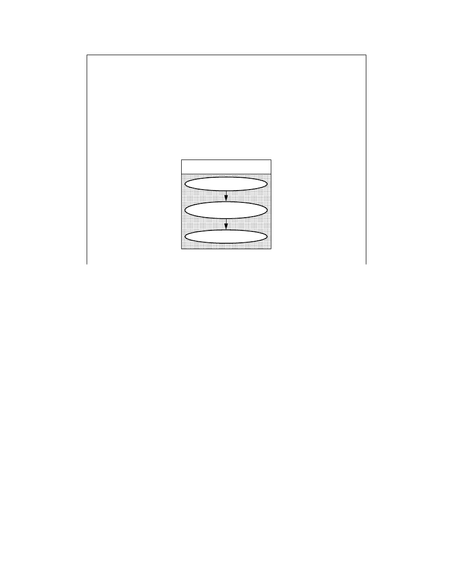
LabVIEW Advanced 1 Course Manual
309
© National Instruments Corporation
LV Adv I 309
Calling WIN32 DLLs from CINs
• A 32-bit dynamic link library (DLL) is a code that a
program can call at any point during its code
execution. There are many DLLs that allow you to
link code to a system task or a specific hardware
function. No special techniques are necessary to
call a Windows 95/NT/98 DLL.
Calling a 32-bit DLL
Load the DLL
Get the function address
Call the function
To call a Windows 95/NT/98 32-bit DLL, no special techniques are required. You would use the
same technique that you would use ordinarily in a “C” program. Dynamic Link Libraries can either
be implicitly loaded by Windows or must be explicitly loaded by the calling application using the
LoadLibrary function. To call your DLL implicitly through your CIN, you should generate an import
library (
.lib
) for your DLL. Then in your
.lvm
file, place the name of that import library in the
expression that defines the symbol CinLibraries. (for example,
cinLibraries = libc.lib
yourDLL.lib
). You need not specify the full path to the import library if it is in one of the paths
defined by the compiler. Also, prototype the function in a header file.
Note: If you are using the Visual C++ IDE, you can just add the .lib file to your project.
The three steps in explicitly calling a DLL are to first load the DLL, get the address of the function in
the DLL you would like to call, and then call the function.

LabVIEW Advanced 1 Course Manual
310
© National Instruments Corporation
LV Adv I 310
Calling WIN32 DLLs
1. Load the DLL
2. Get the address of the desired function
HINSTANCE hinstLib;
hinstLib = LoadLibrary("library name");
MYPROC ProcAdd;
ProcAdd=(MYPROC)GetProcAddress(hinstLib,
"function name");
3. Call the function
*ret_value=(ProcAdd)
(param1, param2, …..);
The functions used for loading a Dynamic Link Library are explained in the slide above. The
first function is the
LoadLibrary
function, which is used to load the DLL by its name. For
example, the code in the slide above returns a handle to the library specified by “
library
name
”. The
GetProcAddress
function returns the address of the function whose name is
specified in
function name
. Finally, you can call the function using its address as shown
above. Next, you will work on an exercise that uses these functions to call a Windows DLL.

LabVIEW Advanced 1 Course Manual
311
© National Instruments Corporation
LV Adv I 311
Exercise 4-4
Students will examine code that shows how to call a
WIN32 system DLL from a CIN.
Time to complete: 15 min.

LabVIEW Advanced 1 Course Manual
312
© National Instruments Corporation
LV Adv I 312
Summary
• The shared external routine is a LabVIEW
subroutine that you call from your CIN, but only
LabVIEW loads and then links to your code
resource. Your CIN code does not include the
subroutine code.
• The external subroutine code has only the
LVSBMain main entry, and the calling code
resource references the shared external routine by
its name.
• You must prepare the calling code for LabVIEW
with new or different directives that tell LabVIEW to
load the external resources when the CIN is loaded.

LabVIEW Advanced 1 Course Manual
313
© National Instruments Corporation
LV Adv I 313
Summary cont....
• When you design your code, decide whether it is
appropriate to use code globals or data space
globals. If you have only one CIN and the VI is not
reentrant, it doesn’t matter which method you
choose.
• Code globals affect the same set of global variables
for any number of references to the CIN in memory.
CIN data space globals affect a different set of
globals for each CIN reference call in memory when
a VI is reentrant.

LabVIEW Advanced 1 Course Manual
314
© National Instruments Corporation
LV Adv I 314
Summary cont....
• A CIN node that is orange in color is marked as
thread-unsafe. A CIN node that is pale yellow is
marked as thread-safe.
• The inclusion of the CINProperties function allows
you to set whether LabVIEW treats the CIN as
thread-safe or not.
• No special techniques are necessary to call a
Windows 95/NT/98 DLL. You can call DLLs the way
you ordinarily would in a Windows 95/NT/98
program.

LabVIEW Advanced 1 Course Manual
315
© National Instruments Corporation
LV Adv I 315
Lesson 5
Calling DLLs
You Will Learn:
• About DLLs.
• About WIN16 DLLs.
• About WIN16 DLLs versus Win32 DLLs.
• About LabVIEW’s Call Library Function.
Introduction
This lesson discusses basic Dynamic Link Library (DLL) concepts.

LabVIEW Advanced 1 Course Manual
316
© National Instruments Corporation
LV Adv I 316
What is a DLL?
• Dynamic linking is a mechanism that links
applications to libraries at run time. These
libraries are called Dynamic Link Libraries
(DLLs) to emphasize the fact that DLLs link to
an application when it is run, rather than when it
is created.
• A DLL consists of:
– A special function(DllMain)
– Several programmer-defined functions to
accomplish common tasks.
Dynamic linking is a mechanism for linking applications to libraries at run time. The libraries
remain in their own files and are not copied into the executable files of the applications. These
libraries are called Dynamic Link Libraries (DLLs) to emphasize the fact that DLLs link to an
application when it is run, rather that when it is created.
DLLs consist of a few special functions and a number of programmer-defined functions to
accomplish common tasks, such as computing the square root of a number or allocating
memory.
When an application uses a DLL, the operating system automatically loads the DLL into
memory. The DLL linkage is specified in the IMPORTS section of the module definition file as
part of the compile, or you can explicitly load the DLL using the loadLibrary() function.
Note: DLLs can be placed in files with different extensions such as
.EXE
,
.DRV
or
.DLL
.

LabVIEW Advanced 1 Course Manual
317
© National Instruments Corporation
LV Adv I 317
WIN16 DLLs
LabVIEW calls
• 16-bit DLLs under Windows 3.1
• 32-bit DLLs under Windows 95/NT/98
Note: If you have a 16-bit DLL that you would like
to call from LabVIEW for Windows 95/NT/98, you
must either recompile the DLL as a 32-bit DLL or
create a “thunking” DLL.
LabVIEW can call only 16-bit DLLs under Windows 3.1; under Windows 95/NT/98, DLLs must be
32-bit. If you want to call a 16-bit DLL from LabVIEW for Windows 95/NT/98, you must either
recompile the DLL as a 32-bit DLL or create a “ thunking” DLL.
The way in which WIN32 DLLs call 16-bit DLLs is called a thunk. The main difference between the
32-bit world and the 16-bit world is the way in which memory is addressed. In the 16-bit world,
Windows 3.1 uses a segmented memory architecture in which a segment:offset addressing scheme is
used to access up to 4 GB of memory. To specify an address in memory, you must specify a segment
and the offset within that segment. A pointer that includes information on both segment and offset is
called a FAR pointer. A pointer that specifies only the offset is called a NEAR pointer. LabVIEW
passes FAR pointers to DLLs. If you are passing more than 64 KB of data to a DLL, you must use
the HUGE pointer type, which is selectable from LabVIEW. In the 32-bit world, 4 GB can be
accessed using a flat pointer rather than the segment:offset style. The process of thunking allows
code from one side of the 16-32 process boundary to call into the other side of the boundary.
Windows 95 supports a thunk compiler, which enables a WIN32-based application to load and call a
16-bit DLL.
For more information on thunking, please refer to the Microsoft documentation.
Note: For information on using 16-bit DLLs with LabVIEW, refer to Application Notes 057 and
072, How to Call Windows 3.X 16-Bit Dynamic Link Libraries (DLLs) from LabVIEW, and
Writing Windows 3.X 16-Bit Dynamic Link Libraries (DLLs) and Calling Them from LabVIEW.
These application notes are available from www.natinst.com.

LabVIEW Advanced 1 Course Manual
318
© National Instruments Corporation
LV Adv I 318
WIN16 DLLs Vs. WIN32 DLLs
DLLs can use either C or
Pascal calling convention.
LabVIEW provides the HUGE
pointer type for arrays and
strings larger than 64 KB.
LabVIEW arrays can be passed
only as an Array Data Pointer.
You can use both the void and
integer return types.
LabVIEW strings can be passed
as C or Pascal-style strings,
depending on the DLL called.
DLLs can use either C or the
Default (stdcall) calling
convention.
You do not need to be concerned
about HUGE, NEAR, or FAR
pointer types.
LabVIEW arrays can be passed
as an Array Data Pointer or as a
LabVIEW Array Handle.
You can use void, integer, and
float return types.
LabVIEW strings can be passed
as C or Pascal string pointers, or
as a LabVIEW string handle,
depending upon the DLL called.
Some of the differences between calling WIN16 and WIN32 DLLs from LabVIEW are
specified in the table above.
The default calling convention for C and C++ programs is C calling convention. It passes
arguments in reverse order, right to left. The stack is cleaned up by the caller. The “C”
calling convention creates a larger executable than _stdcall, because it requires each
function call to include stack cleanup code. The stdcall calling convention also passes
arguments from right to left. The callee is responsible for cleaning up the stack.
Functions that use this calling convention require a function prototype.
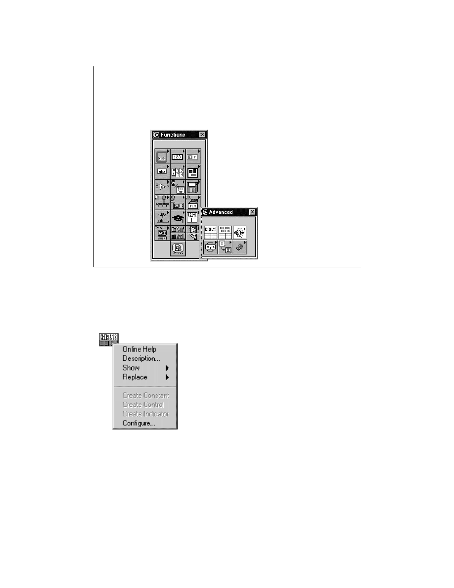
LabVIEW Advanced 1 Course Manual
319
© National Instruments Corporation
LV Adv I 319
The Call Library Function and
Win32 DLLs
LabVIEW features the Call Library Function node to
access your DLLs.
Note: LabVIEW for
WIN95/NT/98 calls
Windows 32-bit DLLs.
The Call Library Function is located in the Advanced subpalette of the Functions palette.
To configure the Call Library Function to call a specific function within a DLL, pop up on the
icon and select the Configure... option, as shown below:
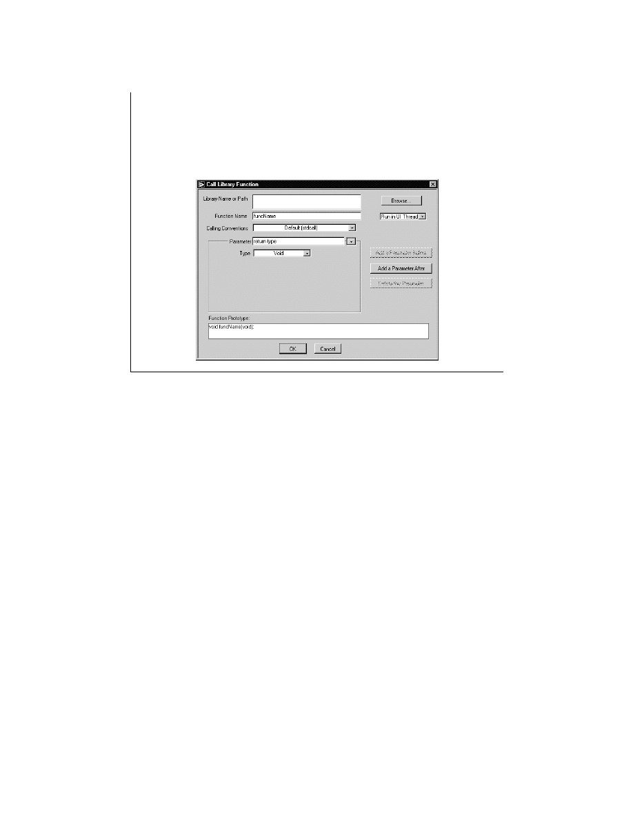
LabVIEW Advanced 1 Course Manual
320
© National Instruments Corporation
LV Adv I 320
The Call Library Function and
Win32 DLLs
0 4
0 5
0 6
0 7
0 8
0 0
str[0] = H
str[1] = e
str[2] = l
str[3] = l
str[4] = o
cnt = 5
In the configuration window, you specify the DLL
function to call and the function parameters.
To call a function in a DLL, you need to know the following information:
•
The data type returned by the function. You can use LabVIEW to call functions that return
void, numeric, or string data types (signed or unsigned 8, 16, and 32-bit integers, or 32-bit
and 64-bit floating point data types).
•
The calling convention used. Both C and Default (stdcall) conventions are available. The
Win32 API uses the Default (stdcall) convention, whereas most user-written DLLs use the C
convention.
•
The parameters to be sent to the function, their types, and the order in which they must be
passed. The parameters can be of void, numeric, arrays, strings or Adapt to type.
•
The location of the DLL on your computer.
•
Whether the DLL can be called safely by multiple threads simultaneously.
The above information can be obtained from the documentation of the DLL, or, if it is a system
DLL, from the appropriate Win32 include file (
windows.h
,
winuser.h
, and so on).
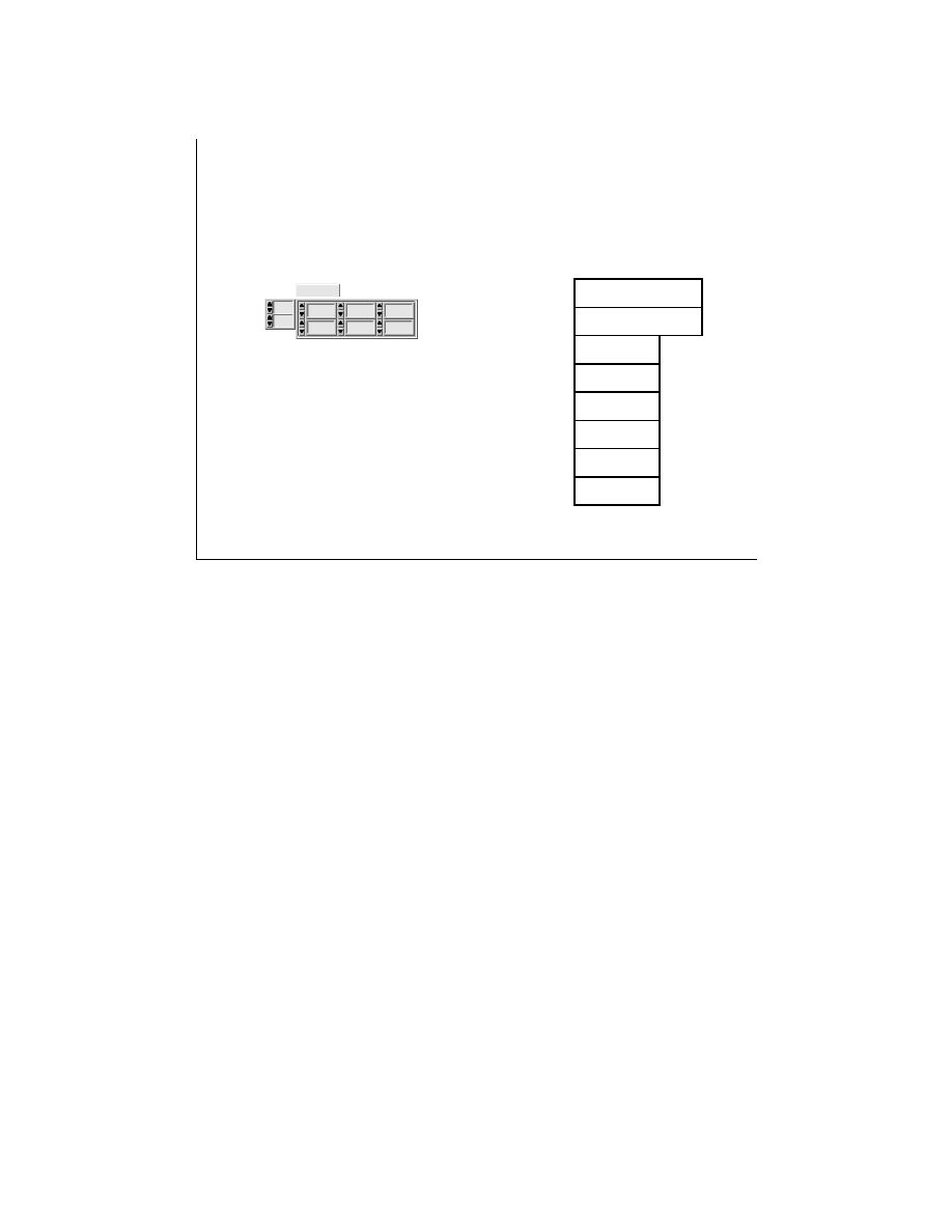
LabVIEW Advanced 1 Course Manual
321
© National Instruments Corporation
LV Adv I 321
The Call Library Function and
Win32 DLLs
5
6
1
2
3
4
0
0
2D Array
1 6
1 8
0 4
0 8
1 0
1 2
14
0 0
data [1][2]
data [1][1]
data [1][0]
data [0][2]
data [0][1]
data [0][0]
dimSizes[0] = 2
dimSizes[1] = 3
The function parameters can be of the following
types:
• Void
• Numerics
- Signed and unsigned versions of 8-bit,
16-bit, and 32-bit integers.
- 4-byte, single-precision numbers
- 8-byte, double-precision numbers
• Arrays
- Array Data Pointer
- Array Handle
• Strings
- C, Pascal, or G.
•Adapt to Type
The Call Library Function allows you to select the following return types and parameters for
your DLL.
Void—The type void is accepted only for the return value. This is not available for parameters.
You should use this return value if your function does not return any values.
Numerics—For numeric data types, you must specify the exact numeric type out of the
following items:
•
Signed and unsigned versions of 8-bit, 16-bit, and 32-bit integers.
•
Four-byte, single-precision numbers.
•
Eight-byte, double-precision numbers.
You must use the format ring to indicate if you want to pass the value or a pointer to the value.
Arrays—You can indicate the data type of arrays (using the same items as for numeric data
types), the number of dimensions, and the format to use in passing the array. Use the Format
item to select if you want to pass an Array Data Pointer or an Array Handle. If you use the
Array Data Pointer, pass the array dimension as separate parameter(s).
Strings—You should specify the format for strings. The items can be C, Pascal, or G
(LabVIEW). Choose the string format that the DLL function expects. If the library function you
are calling is written specifically for G, you might want to use the String Handle format, which
is a pointer to a pointer to four bytes for length information, followed by string data.

LabVIEW Advanced 1 Course Manual
322
© National Instruments Corporation
LV Adv I 322
MessageBoxA function
return type
function name
int MessageBoxA (hWnd, lpText, lpCaption, uType)
parameters
Parameters:
HWND
hWnd 32-bit unsigned
integer. Identifies the parent
window. In this case, it is
NULL.
LPCSTR pText C-style string
LPCSTR lpCaption C-style string
UINT
uType unsigned 32-bit
integer value.
Return Type:
int 32-bit signed integer
In the next exercise, you will call the MessageBoxA function from the user32.dll via the Call
Library Function node. We have already called this function through a CIN in Lesson 4.
LabVIEW Advanced 1 Course Manual
323
© National Instruments Corporation
LV Adv I 323
Multithreading and
the Call Library Function
Thread-Unsafe
Call Library Node
Thread-Safe
Call Library Node
From LabVIEW 5.0 onwards, the Call Library Node, by default, runs in the user interface
thread or a single thread. Hence, when you first select the Call Library Node function, it
appears orange in color. To mark your DLL thread safe or reentrant, choose the Reentrant
option in the Configuration window, as shown on the next slide.
When you mark your DLL as thread safe, the Call Library node changes to a yellow colored
icon, indicating that the function in the DLL is thread safe. A DLL is defined to be thread
safe if it can be reliably called from two or more separate threads.
For a DLL to be truly thread safe, regardless of how it is identified, you should follow some
guidelines. These are discussed in the next lesson. Lesson 4 has already discussed the
guidelines for creating a thread-safe CIN.
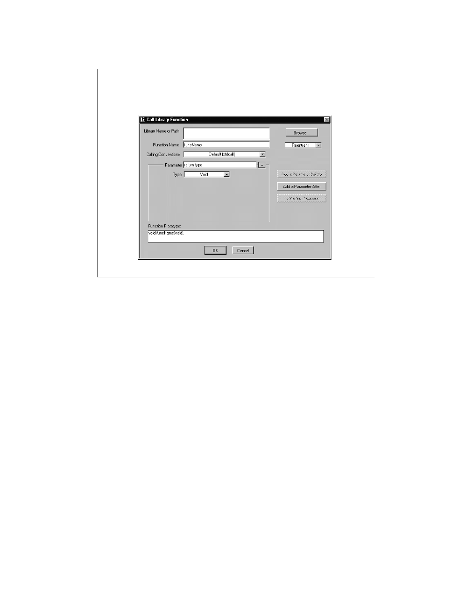
LabVIEW Advanced 1 Course Manual
324
© National Instruments Corporation
LV Adv I 324
Thread-Safe Call Library Node

LabVIEW Advanced 1 Course Manual
325
© National Instruments Corporation
LV Adv I 325
Exercise 5-1 (Windows 95/NT/98 only)
Students will call the MessageBoxA
function in user32.dll.
Time to complete: 20 min.

LabVIEW Advanced 1 Course Manual
326
© National Instruments Corporation
LV Adv I 326
Exercise 5-2
Students will call the FindWindowA and
FlashWindow functions in user32.dll
Time to complete: 15 min.

LabVIEW Advanced 1 Course Manual
327
© National Instruments Corporation
LV Adv I 327
Debugging Call Library
Function Errors
If you see a Broken Run arrow in LabVIEW or if your VI crashes,
check the following:
•
Make sure that the path to the DLL file is correct.
•
If you get the error message Function not found in library, check
the spelling, syntax, and case sensitivity of the function name
you want to call.
•
Make sure that all the parameters passed to a DLL function
have data wired to all of the input terminals of the Call Library
Function icon. Be sure to properly configure the function for
all
input parameters.
•
Make sure you use the proper calling convention (C or
Default(stdcall)). The Win32 API uses the Default(stdcall)
convention.
After configuring the Call Library Function dialog box, if you still see a broken run arrow in
LabVIEW or if your VI crashes, check the following points. Some of the points have already
been mentioned on the slide above.
•
Make sure the path to the DLL file is correct.
•
If you get the error message “ function not found in library,” check the spelling, syntax, and
case sensitivity of the function name you want to call.
•
Make sure that all the parameters passed to a DLL function have data wired to all of the
input terminals of the Call Library Function icon. Be sure to properly configure the function
for all input parameters.
•
Check that the return types and data types of arguments for your functions exactly match the
data types your function uses. Failure to do so may result in crashes.
•
Make sure you use the proper calling convention (C or Default (stdcall)). The Win32 API
uses the Default (_stdcall) convention.
•
Make sure that you pass the correct order of the arguments to the function.
•
When passing strings to a function, select the correct type of string to pass—C or Pascal
string pointers, or LabVIEW string handle. The Win32 API uses the C-style string pointer.
Note: Calling shared libraries written and compiled in C++ has not been tested and might not
work.

LabVIEW Advanced 1 Course Manual
328
© National Instruments Corporation
LV Adv I 328
Summary Lesson 5
• Dynamic linking is a mechanism that links applications to libraries at
run time. These libraries are called Dynamic Link Libraries (or DLLs) to
emphasize the fact that DLLs link to an application when it is run,
rather that when it is created.
• LabVIEW can call only 16-bit DLLs under Windows 3.1. Under
Windows 95/NT/98, DLLs must be 32-bit. If you have a 16-bit DLL that
you like to call from LabVIEW for Windows 95/NT/98, you must either
recompile the DLL as a 32-bit DLL or create a “thunking” DLL.
• LabVIEW features the Call Library Function node to offer easy access
to your 16-bit and 32-bit Dynamic Link Libraries.
• In Windows 3.1, you can view function names with utilities such as
exemap.exe and exehdr.exe, which come with your compiler.
• In Windows 95, you can use QuickView to view the exported function
names within a 32-bit DLL. If you have the Visual C++ compiler
installed on your machine, you can also use the dumpbin utility to
view exported function names.

LabVIEW Advanced 1 Course Manual
329
© National Instruments Corporation
LV Adv I 329
Summary Lesson 5
• To call a function in a DLL, you need to know the data type
returned by the function, the calling convention used, the
parameters to be sent to the function, their types and the order
in which they must be passed, the location of the DLL on your
computer, and if the function can be called safely by multiple
threads simultaneously.

LabVIEW Advanced 1 Course Manual
330
© National Instruments Corporation
LV Adv I 330
Lesson 6
Writing DLLs
You Will Learn:
• About the anatomy of a DLL.
• About writing a DLL in LabWindows/CVI.
• About writing a DLL in Microsoft Visual C++.
• About array and string options.
• Troubleshooting the Call Library Function.
This lesson discusses how you can create simple 32-bit DLLs and call them in LabVIEW.
Because a DLL uses a format that is standard among several development environments,
you should be able to use almost any development environment to create a DLL that
LabVIEW can call.

LabVIEW Advanced 1 Course Manual
331
© National Instruments Corporation
LV Adv I 331
Anatomy of a DLL
The following code shows the basic structure of a DLL:
BOOL WINAPI DllMain(HINSTANCE hinstDLL,
DWORD fdwReason, LPVOID
lpvReserved {
switch (fdwReason){
case DLL_PROCESS_ATTACH:
/* Init Code here */
break;
case DLL_THREAD_ATTACH: /* Thread-specific init code here */
break;
case DLL_THREAD_DETACH: /* Thread-specific cleanup code
here. */
break;
case DLL_PROCESS_DETACH: /* Cleanup code here */
break;
}
/* The return value is used for successful DLL_PROCESS_ATTACH */
return TRUE;
}
/* One or more functions */
__declspec (dllexport) DWORD Function1(....){}
__declspec (dllexport) DWORD Function2(....){}
As shown in the example code above, in Win32, the DllMain function is called when a DLL is
loaded or unloaded. The DllMain function is also called when a new thread is being created in a
process already attached to the DLL, or when a thread has exited cleanly. Finally, a DLL also
contains functions that perform the activities the DLL expects to accomplish. These functions
are exported by using the _declspec (dllexport) keyword when prototyping and declaring
functions. The _declspec (dllexport) keyword is a Microsoft-specific extension to the C or C++
language. Other compilers will have different keywords. Check the documentation for your
compiler for the correct keywords.
Alternately, the EXPORTS section in module definition files can be used to export functions.
For more information about module definition files, please refer to the Example-Writing a DLL
in Microsoft Visual C++ 5.0 section.
The
DllMain
function has the
WINAPI
keyword before it.
WINAPI
is typedefed to
_stdcall
in the
windef.h
header file. This defines the calling convention for the function.

LabVIEW Advanced 1 Course Manual
332
© National Instruments Corporation
LV Adv I 332
Writing a DLL in LabWindows/CVI
• If you do not explicitly define a DllMain,
LabWindows/CVI will create a default one that
does nothing.
• In addition to the source code, you should
create a header file containing the prototypes
of the functions you want exported from
the DLL.
In some cases, you may want to write your own DLL (for example, to communicate with your
own custom-built hardware). In this section, you will find sample code that illustrates how to
create a simple DLL using the LabWindows/CVI compiler. Creating DLLs is no more
difficult than creating a static C library or object. Although they behave differently (DLLs are
linked at run time, while static libraries are linked when the build occurs), the source code can
be identical. For example, you should be able to take an existing source file, change the target
in LabWindows/CVI to Dynamic Link Library, and build the DLL.
One difference in source code is that a DLL contains a DllMain function. The DllMain
function is called when an application loads and unloads the DLL. This gives you a
mechanism to do initializations when the DLL is first loaded and to free system resources
when the DLL is unloaded. If you do not explicitly define a DllMain, LabWindows/CVI will
create a default one that does nothing.
In addition to the source code, you should create a header file containing the prototypes of the
functions you want exported from the DLL. You need to let the compiler know which
functions to export, because DLLs can have many functions, some of which are used
internally by the DLL and not exposed to any calling program. All exported functions can be
called by external modules.

LabVIEW Advanced 1 Course Manual
333
© National Instruments Corporation
LV Adv I 333
Exercise 6-1
Students will create a simple DLL using the
LabWindows/CVI compiler.
Time to complete: 15 min.

LabVIEW Advanced 1 Course Manual
334
© National Instruments Corporation
LV Adv I 334
Writing a DLL in Microsoft
Visual C++ 5.0
To create a DLL, you need the following four files:
• A C Language source file (required)
• A custom header file (optional - may be part of
the source code)
• A module definition file (optional - may be
required if using _stdcall calling convention - or
functions can be exported by
using the
keyword
dllexport)
• A make file, or set compiler options to generate a
DLL (required - except when some development
environments create and execute the make file)
In this section, you will learn to write a DLL using the Visual C++ 5.0
compiler. To create a DLL, you will need the following four files:
•
A C language source file (required)
•
A custom header file (optional—may be part of the source code)
•
A module definition file (optional—may be required if using the _stdcall calling
convention—or functions can be exported by using the keyword dllexport)
•
A make file, or set compiler options to generate a DLL (required—except when some
development environments create and execute the make file)

LabVIEW Advanced 1 Course Manual
335
© National Instruments Corporation
LV Adv I 335
C Language Source File
When writing “C” source files, you must decide the following:
•
Which calling convention to use: the C or _stdcall.
•
Exporting functions in the DLL by using the _declspec
(dllexport) keyword or exporting functions using the
module definition file.
If you use the standard calling convention:
• You may need to export the correct function names using
the module definition file.
• _stdcall calling convention may put an “_” (underscore) in
front of a function name.
If your source file has a .cpp extension:
• Visual C++ mangles or changes the function names. Visual
C++ refers to “mangling” as “name decoration.” You can
use QuickView in Windows 95 to determine how a name
was decorated.
When you write the C language source file for the DLL, you need to decide which calling
convention to use: the C or _stdcall calling convention. Functions can be exported by using the
declspec (dllexport) keyword. Declaring the dllexport keyword eliminates the need for exporting
a function via the module definition file. If you would like to use the standard calling
convention using the stdcall keyword in your code, you may need to export the correct function
names in your DLL using the module definition file. You may need to do this because stdcall
may put an “_” (underscore) in front of your function name. If your source code has a
.cpp
extension, the Visual C++ compiler will always mangle names. To prevent name decoration,
you must declare the functions with extern “ c.” However, if you do not declare your functions
with extern “ c,” you still may be able to call your functions if you can find the mangled names.
Visual C++ refers to mangling as “ name decoration.” You can use QuickView in Windows 95
(or
Dumpbin.exe
from the
msdev\bin
directory of your Visual C++ compiler) to
determine how a name was decorated.

LabVIEW Advanced 1 Course Manual
336
© National Instruments Corporation
LV Adv I 336
The Module Definition File
A Module Definition File (.def) contains the statements for
defining a DLL.
• The LINK option in Project Setting of the Visual C++
compiler provides equivalent command line options for
most module-definition statements, and hence a typical
program for Win32 does not require a .def file.
• The only mandatory statements are the LIBRARY statement
and the EXPORT statement.
• The LIBRARY statement is the first statement and identifies
the name of the DLL.
• The EXPORTS statement lists the names of the functions
exported by the DLL.
A module definition file (
.def
) can be associated with a DLL file. The
.def
file contains the
statements for defining a DLL (for example, the name of the DLL and the functions it exports).
The LINK option in Project Settings of the Visual C++ compiler provides equivalent command-
line options for most module-definition statements, and hence a typical program for Win32 does
not usually require a
.def
file. The only mandatory entries in the
.def
files are the LIBRARY
statement and the EXPORT statement. The LIBRARY statement must be the first statement in
the file. The name specified in the LIBRARY statement identifies the library in the DLL’s
import library. The EXPORT statement lists the names of the functions exported by the DLL.
If you were using the _stdcall calling convention in your DLL, you would need to use the
module definition file to export the functions that the DLL exposes. This must be done because
the compiler decorates the function names.

LabVIEW Advanced 1 Course Manual
337
© National Instruments Corporation
LV Adv I 337
The Module Definition File
If you were using the _stdcall calling convention in
your DLL, you would have to use the module
definition file to export the correct function names.
LIBRARY ourDLL
EXPORTS
avg_num
add_num
numIntegers
An Example Module Definition File
A module definition file (
.def
) can be associated with a DLL file. The
.def
file contains the
statements for defining a DLL (for example, the name of the DLL and the functions it exports).
The LINK option in Project Settings of the Visual C++ compiler provides equivalent command-
line options for most module-definition statements, and hence a typical program for Win32 does
not usually require a
.def
file. The only mandatory entries in the
.def
files are the LIBRARY
statement and the EXPORT statement. The LIBRARY statement must be the first statement in
the file. The name specified in the LIBRARY statement identifies the library in the DLL’s
import library. The EXPORT statement lists the names of the functions exported by the DLL.
If you were using the _stdcall calling convention in your DLL, you would need to use the
module definition file to export the functions that the DLL exposes. If you use a source file with
the
.cpp
extension, the compiler decorates function names. You can either declare the
functions as extern “ c” or use a module definition file.

LabVIEW Advanced 1 Course Manual
338
© National Instruments Corporation
LV Adv I 338
Exercise 6-2A
Students will create a simple DLL
using the Visual C++ compiler.
Time to complete: 15 min.

LabVIEW Advanced 1 Course Manual
339
© National Instruments Corporation
LV Adv I 339
Exercise 6-2B
Students will create a simple DLL
using the LabWindows/CVI compiler.
Time to complete: 15 min.

LabVIEW Advanced 1 Course Manual
340
© National Instruments Corporation
LV Adv I 340
Writing Thread-Safe DLLS
Your shared library
• Does not have any global storage data( global variables,files on
disk, etc).
• AND it does not access any hardware (register-level programming)
• AND it does not call any functions/shared libraries/drivers that are
thread-unsafe
Your shared library protects
• With semaphores or mutexes access to those global resources
OR
DLLs are thread-safe if:
OR
Your shared library
• Is called from one nonreentrant VI
We have reviewed some of the guidelines for writing thread-safe CINs in Lesson 4. Most of the
guidelines for writing thread-safe DLLs are similar and are listed on the slide above. For
detailed information on programming thread-safe DLLs, please consult your favorite book on C
programming.

LabVIEW Advanced 1 Course Manual
341
© National Instruments Corporation
LV Adv I 341
Arrays Options
Arrays of numeric data can be:
• Any integer type
• Single (4-byte) precision floating-point numbers
• Double (8-byte) precision floating-point numbers
If you pass an array data pointer:
• Do not resize the array within the DLL, because the
array pointer refers to LabVIEW data.
• If you need to return an array of data, allocate an array
of sufficient size in LabVIEW, pass it to your function,
and have it act as the buffer
If you pass a LabVIEW Array Handle:
• You can use the LabVIEW CIN functions (such as
Numeric Array Resize) to resize the array within
the DLL.
Arrays of numeric data can be of any integer type, or single-precision (4-byte) or double-
precision (8-byte) floating-point numbers. When you pass an array of data to a DLL function,
you will see that you have the option to pass the data as an Array data pointer or as a LabVIEW
Array Handle. When you pass an Array Data Pointer, you can also set the number of dimensions
in the array, but you do not include information about the size of the array dimension(s). DLL
functions either assume the data is of a specific size or expect the size to be passed as a separate
input. Also, because the array pointer refers to LabVIEW data, do not resize the array within
the DLL using system functions, such as realloc. Doing this may cause your computer to crash.
If you need to return an array of data, allocate an array of sufficient size in LabVIEW, pass it to
your function, and have it act as the buffer. If the data takes less space, you can return the
correct size as a separate parameter and then, on the calling diagram, use array subset to extract
the valid data.
Alternately, if you pass the array data as a LabVIEW Array Handle, you can use the LabVIEW
CIN functions (such as NumericArrayResize) to resize the array within the DLL. To call
LabVIEW CIN functions from your DLL while using the Visual C++ compiler, you must
include the
labview.lib
library in the
LabVIEW/cintools/Win32
directory. Also, to
access these CIN functions using the Symantec compiler, you must link to the
labview.sym.lib
library in the
LabVIEW/cintools/win32
directory.
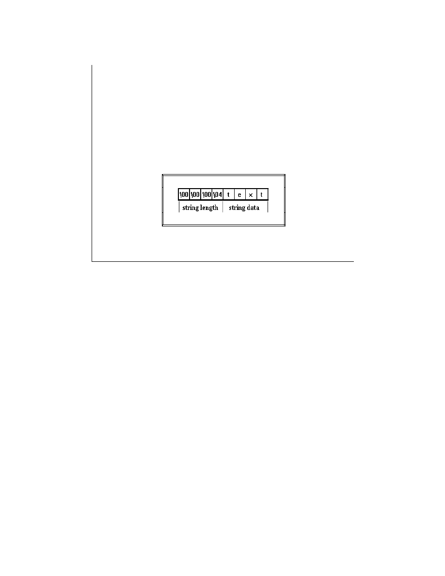
LabVIEW Advanced 1 Course Manual
342
© National Instruments Corporation
LV Adv I 342
String Options
The Call Library function works with:
• C String Pointers
• Pascal String Pointers
• LabVIEW String Handles
The LabVIEW String Format
Recall that LabVIEW stores strings as arrays (that is, structures pointed to by handles). The Call
Library Function works with C and Pascal-style string pointers or LabVIEW String Handles.
You already have studied the structure of LabVIEW string handles. You now will review the
difference between these three formats, as explained below.
You can think of a string as an array of characters; assembling the characters in order forms a
string. LabVIEW stores a string in a special format in which the first four bytes of the array of
characters form a signed 32-bit integer that stores how many characters appear in the string.
Thus, a string with n characters will require n + 4 bytes to store in memory. For example, the
string text contains four characters. When LabVIEW stores the string, the first four bytes contain
the value 4 as a signed 32-bit number, and each of the following four bytes contains a character
of the string. The advantage of this type of string storage is that NULL characters are allowed in
the string. Strings are virtually unlimited in length (up to 2
31
characters). This method of string
storage is shown above.
The Pascal string format is nearly identical to the LabVIEW string format, but instead of storing
the length of the string as a signed 32-bit integer, it is stored as an unsigned 8-bit integer. This
limits the length of a Pascal style string to 255 characters. A graphical representation of a Pascal
string appears on the next slide. A Pascal string that is n characters long will require n + 1 bytes
of memory to store.
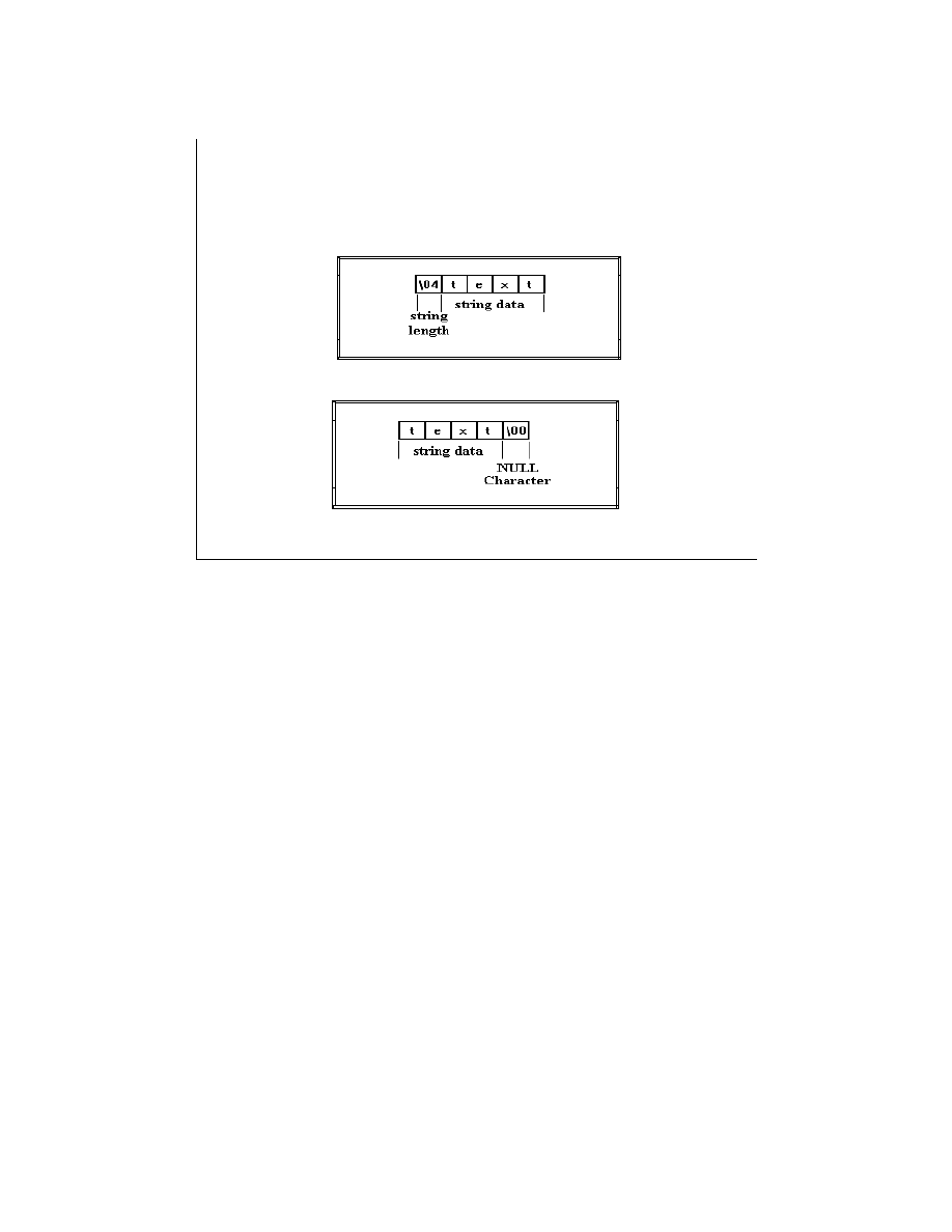
LabVIEW Advanced 1 Course Manual
343
© National Instruments Corporation
LV Adv I 343
String Options
The Pascal String Format
The C String Format
C strings are probably the type of strings you will deal with most often. The similarities between the C-
style string and normal numeric arrays in C becomes much clearer when one observes that C strings are
declared as char *. C strings do not contain any information that directly gives the length of the string, as
do the LabVIEW and Pascal strings. Instead, C strings use a special character, called the NULL
character, to indicate the end of the string. NULL is defined to have a value of zero in the ASCII
character set. Note that this is the number zero and not the character “ 0” .
Thus, in C, a string containing n characters requires n + 1 bytes of memory to store: n bytes for the
characters in the string and one additional byte for the NULL termination character. The advantage of C-
style strings is that they are limited in size only by available memory. However, if you are acquiring data
from an instrument that returns numeric data as a binary string, as is common with serial or GPIB
instruments, values of zero in the string are possible. For binary data where NULLs may be present, you
probably should use an array of unsigned 8-bit integers. If you treat the string as a C-style string, your
program will assume incorrectly that the end of the string has been reached, when in fact your instrument
is returning a numeric value of zero. The way a C-style string is stored in memory is shown above.
When you pass a C string pointer or a Pascal string pointer from LabVIEW to a DLL, you must follow
the same guidelines as for arrays. Specifically, never resize a string, concatenate strings, or perform
operations that may increase the length of string data passed from LabVIEW. If you must return data as a
string, you first should allocate a string of the appropriate length in LabVIEW and pass this string into
the DLL to act as a buffer.
If you pass a LabVIEW String Handle from the Call Library function to the DLL, you can use the
LabVIEW CIN functions such as DSSetHandleSize to resize the LabVIEW string handle. Also, you will
need to add
labview.lib
to your project if you are using Visual C++ and
labview.sym.lib
if
you are using the Symantec compiler from the
LabVIEW/cintools/Win32
directory while building
your DLL.

LabVIEW Advanced 1 Course Manual
344
© National Instruments Corporation
LV Adv I 344
String Options
If you pass a C or Pascal string pointer:
• Do not resize the string within the DLL, because
the string pointer refers to LabVIEW data.
• If you need to return an array of data, allocate a
string of appropriate length in LabVIEW, pass this
string to your function, and have it act as the
buffer
If you pass a LabVIEW String Handle:
• You can use the LabVIEW CIN functions (such as
DSSetHandleSize) to resize the LabVIEW String
Handle within the DLL.

LabVIEW Advanced 1 Course Manual
345
© National Instruments Corporation
LV Adv I 345
Array and String Options
The LabVIEW CIN function calls can be made only
by adding labview.lib, located in the LabVIEW
/cintools/Win32 directory (for Visual C++ compiler)
and labview.sym.lib, located in the
LabVIEW/cintools/Win32 directory (for Symantec
compiler) to your project while building your DLL.

LabVIEW Advanced 1 Course Manual
346
© National Instruments Corporation
LV Adv I 346
Exercise 6-3A
Students will create a 32-bit DLL with two exported
functions using the Visual C++ compiler
and calling them from LabVIEW.
Time to complete: 15 min.

LabVIEW Advanced 1 Course Manual
347
© National Instruments Corporation
LV Adv I 347
Exercise 6-3B
Students will create a 32-bit DLL with two
exported functions using the CVI compiler
and calling them from LabVIEW.
Time to complete: 15 min.

LabVIEW Advanced 1 Course Manual
348
© National Instruments Corporation
LV Adv I 348
Exercise 6-4
Students will create a 32-bit DLL with one exported
function containing a CIN function to resize an array
using the Visual C++ compiler.
Time to complete: 15 min.

LabVIEW Advanced 1 Course Manual
349
© National Instruments Corporation
LV Adv I 349
Troubleshooting the
Call Library Function
• Make sure you use the proper calling convention (C or
stdcall).
•
NEVER resize arrays or concatenate strings using the
arguments passed directly to a function. Remember, the
parameters you pass are LabVIEW data. Changing array or
string sizes may result in a crash by overwriting other data
stored in LabVIEW memory. You MAY resize arrays or
concatenate strings if you pass in LabVIEW Array Handle or
LabVIEW String Handle and are using the Microsoft Visual
C++ compiler or Symantec compiler to compile your DLL.
• When passing strings to a function, remember to select the
correct type of string to pass C or Pascal or LabVIEW string
Handle.
• Pascal strings are limited to 255 characters in length.
If, after configuring the Call Library Function dialog, you still have a Broken Run arrow in
LabVIEW, check to be sure that the path to the DLL file is correct. If LabVIEW gives you an
error message saying the function was not found in the library, double-check the spelling of the
name of the function you want to call. Remember that function names are case sensitive. Also,
recall that you need to declare the function with the _declspec (dllexport) keyword in the header
file and the source code or define it in the EXPORTS section of the module definition file. Even
if you have used the _declspec (dllexport) keyword and are using the _stdcall calling
convention, then you must declare the DLL function name in the EXPORTS section of the
module definition file. If this is not done, a process known as name mangling may have altered
the function names for C++ programs. The function will be exported with the mangled name,
and the actual function name will be unavailable to applications that call the DLL.

LabVIEW Advanced 1 Course Manual
350
© National Instruments Corporation
LV Adv I 350
Troubleshooting the
Call Library Function
• C strings are NULL terminated. If your DLL function returns
numeric data in a binary string format (for example, via GPIB
or the serial port), it may return NULL values as part of the
data string. In such cases, passing arrays of short (8-bit)
integers is most reliable.
• If you are working with arrays or strings of data,
ALWAYS
pass a buffer or array that is large enough to hold any results
placed in the buffer by the function unless you are passing
them as LabVIEW handles, in which case you can resize them
using CIN functions under Visual C++ or Symantec compiler.
• If you are using the _stdcall calling convention, you should
list DLL functions in the EXPORTS section of the module
definition file, as the compiler may add an underscore to the
function names.
If you already have double-checked the name of the function and have properly exported the function,
find out whether you have used the C or C++ compiler on the code. You can do this by checking whether
you saved the source file with the
.cpp
extension. If you have used the
.cpp
extension, the names of
the functions in the DLL will be mangled (or decorated). The easiest way to correct this problem is to
enclose the declarations of the functions you want to export in your header file with the extern “ C”
statement:
extern “C”
{
/* your function prototypes here */
}
After properly configuring the Call Library Function, run the VI. If it does not run successfully, you
might get errors or a General Protection Fault. If you get a General Protection Fault, there are several
possible causes. First, make sure that you are passing exactly the parameters that the function in the DLL
expects. For example, make sure that you are passing an int16 and not an int32 when the function
expects int16. Also, confirm that you are using the correct calling convention—_stdcall or C.
Another troubleshooting option is to try to debug your DLL by using the source level debugger provided
with your compiler. In the Project » Settings » Debug section of Microsoft Visual C++, you can set
Executable for Debug session as
labview.exe
to debug your DLL. Specify the working directory and
the Program argument to be the VI that calls your DLL. Using your compiler’s debugger, you can set
breakpoints, step through your code, watch the values of the variables, etc. Debugging using
conventional tools can be extremely beneficial.
For more information about debugging, please refer to the appropriate manual for your compiler.

LabVIEW Advanced 1 Course Manual
351
© National Instruments Corporation
LV Adv I 351
Troubleshooting the
Call Library Function
• You should
list DLL functions that other applications call in
the module definition file EXPORTS section or include the
_declspec (dllexport) keyword in the function declaration.
• If you save the source code with the .cpp extension, you must
export functions with the extern “C” { } statement in your
header file to prevent name mangling (decoration).
• If you are writing your own DLL, you should not recompile a
DLL while the DLL is loaded into memory by another
application (for example, your VI). Before recompiling a DLL,
make sure that
all applications making use of the DLL are
unloaded from memory. This ensures that the DLL itself is not
loaded into memory. You may fail to rebuild correctly if you
forget this and your compiler does not warn you.
If the function has not been properly exported, you will need to recompile the DLL. Before
recompiling, be sure to close all applications and VIs that may make use of the DLL. If the DLL
is still in memory, the recompile will fail. Most compilers will warn you if the DLL is in use by
an application.

LabVIEW Advanced 1 Course Manual
352
© National Instruments Corporation
LV Adv I 352
Troubleshooting the
Call Library Function
• Test your DLLs with another program to ensure that the
function (and the DLL) behave correctly. Your compiler’s
debugger or a simple C program that allows you to call a
function in a DLL will help you identify whether possible
difficulties are inherent to the DLL, or LabVIEW related.
Calling the DLL from another C program is also an excellent way to debug your DLL. By
doing this, you have a means of testing your DLL independently of LabVIEW, thus helping
identify possible problems more quickly.

LabVIEW Advanced 1 Course Manual
353
© National Instruments Corporation
LV Adv I 353
Summary Lesson 6
• In Win32, the DllMain function is called when a DLL
is loaded or unloaded. Besides the DllMain
function, a DLL also contains functions that
perform the activities it expects to accomplish.
• LabWindows/CVI and Visual C++ are just some of
the compilers you can use to build DLLs.
• The LabVIEW CIN function calls can be made only if
you are using the Visual C++ compiler by adding
labview.lib to your project and if you are using the
Symantec compiler by adding labview.sym.lib to
your project.


©
National Instruments Corporation
1-1-1
LabVIEW Advanced I Course Manual
Module 1
Lesson 1
Exercises
Exercise 1-1
Objective:
To use the memory monitoring tools in LabVIEW to examine a VI.
You will open a LabVIEW example called the Temperature System Demo
VI and monitor its memory usage with each of the methods described.
Instructor’s Note
Make sure multithreading is disabled and the number of undo steps is
set to zero before beginning any exercises. These settings can greatly
affect memory use in LabVIEW.
1. Launch LabVIEW. Select Search Examples from the opening window.
If LabVIEW is already running, select Search Examples from the Help
menu.
2. Open Temperature System Demo.vi from the Demonstrations »
Analysis window.
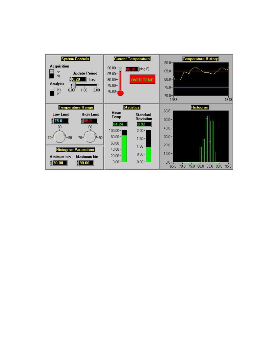
Module 1 Lesson 1 Exercises
LabVIEW Advanced I Course Manual
1-1-2
©
National Instruments Corporation
Front Panel
3. Select About LabVIEW... from the Help menu and note the memory
size here: _____________________
4. Examine the diagram for the Temperature System Demo VI.
5. Return to the panel and run the Temperature System Demo VI.
Observe the operation of the VI for a few seconds and then stop the VI
by clicking off the Acquisition switch.
6. Select Show VI Info... from the Windows menu. Write down the
memory usage for:
Front Panel ______________
Block Diagram ___________
Code ___________________
Data ____________________
VI Total Memory _________
7. Close the Show VI Info window by pressing the OK button.
8. Now you will use the Profile Window to display the memory statistics
for the Temperature System Demo VI. Select Show Profile Window
from the Project menu.
9. Check the Profile Memory Usage box in the Profile window. Press the
Start button, and check the Memory Usage box. Do not close the
Profile window.
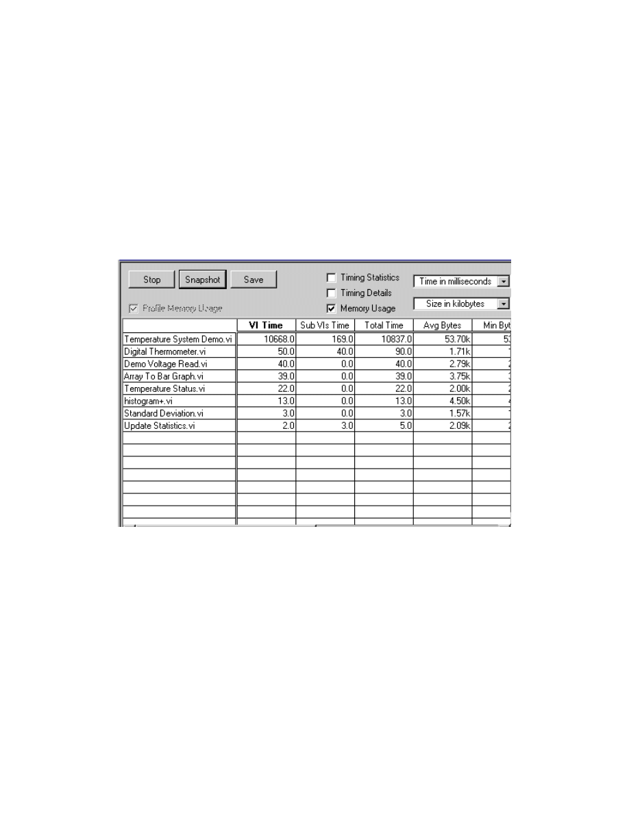
Module 1 Lesson 1 Exercises
©
National Instruments Corporation
1-1-3
LabVIEW Advanced I Course Manual
10. Run the Temperature System Demo VI.
11. While the Temperature System Demo VI is running, press the
Snapshot button in the Profile window. Notice that the data memory for
each subVI is recorded but not for the main VI.
12. Record which subVI is using the most memory:
__________________________ uses ___________ KB
13. Stop the Temperature System Demo VI by clicking off the Acquisition
switch.
14. Return to the Profile window and press the Snapshot button. The Profile
window should resemble the following:
15. Scroll to the memory statistics in the Profile window. Observe the
memory used by each VI in memory.
16. Record how much memory the Temperature System Demo VI used
here: _________________________. Compare this value with the value
for data space memory shown in the Show VI Info window. The
numbers should be similar.
17. Stop the memory profiling by pressing the Stop button. Close the Profile
window and the Temperature System Demo VI.
18. Close the Search Examples window.
End of Exercise 1-1

Module 1 Lesson 1 Exercises
LabVIEW Advanced I Course Manual
1-1-4
©
National Instruments Corporation
Additional Exercises
1-2
Open the Two Channel Oscilloscope VI from Help » Search
Examples » Demonstrations » Instrument I/O. Use the Show VI
Info window to determine the size of the VI components and write
them here:
_______________________Front Panel
_______________________Block Diagram
_______________________Code
_______________________Data
_______________________VI Total Memory
Use the Profile Window to get more memory information. Run the
Two Channel Oscilloscope VI with different settings. Then look at
the memory statistics in the Profile Window. Which subVI used the
most memory? Close the Two Channel Oscilloscope VI when you
are finished.
1-3
Open the Frequency Response VI from Help » Search
Examples » Demonstrations » Instrument I/O. Use the Show VI
Info window to determine the size of the VI components and write
them here:
_______________________Front Panel
_______________________Block Diagram
_______________________Code
_______________________Data
_______________________VI Total Memory
Use the Profile Window to get more memory information. Run the
Frequency Response VI with different numbers of steps and other
settings. Then look at the memory statistics in the Profile Window.
Which VIs used different amounts of memory when you changed the
parameters? Close the Frequency Response VI when you are
finished.
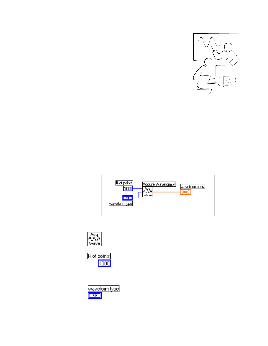
©
National Instruments Corporation
1-2-1
LabVIEW Advanced I Course Manual
Module 1
Lesson 2
Exercises
Exercise 2-1
Objective:
To examine how the front panel and block diagram use memory.
You will create a VI that demonstrates how the front panel and block
diagram use memory as described in the previous section.
Part 1: Observing Front Panel Operate Data
Block Diagram
1. Open a new VI in LabVIEW and build the block diagram shown above.
Acquire Waveform VI (Select a VI… » C:\Exercises\
LV_AdvI\Mod1_mem.llb) generates a waveform of the type,
length, and scaling factor specified.
Numeric Constant (pop up on the # of points [top left]
input of the Acquire Waveform VI with the wiring tool
and select Create Constant from the menu) specifies how
many data points to generate for the waveform. Type the
value of 1000 into the constant.
Enumerated Control (pop up on the waveform type
input [middle left] of the Acquire Waveform VI and
select Create Control from the menu) specifies the
type of waveform to generate.
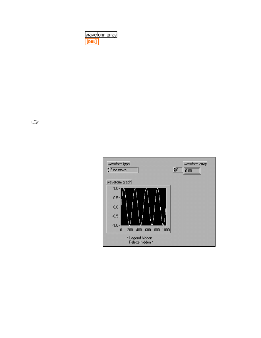
Module 1 Lesson 2 Exercises
LabVIEW Advanced I Course Manual
1-2-2
©
National Instruments Corporation
Numeric Array Indicator (pop up on the waveform
output [right side] of the Acquire Waveform VI and
select Create Indicator from the menu) contains the
waveform array that the subVI generates.
2. Go to the front panel, select a waveform type of a Sine wave, and run
the VI.
3. Select Show VI Info… from the Windows menu to see the memory use
of each component.
The data space for the top-level VI will use approximately 16 KB of
memory. This is because the array has the representation of DBL
(double precision floating point), or 8 bytes per value. The Acquire
Waveform VI generates 1000 values or 8 KB of data. Another 8 KB is
used to display the data in the numeric array indicator on the front panel.
Note
If you are using a version of LabVIEW later than 5.0, the memory use might
be less than reported in the next few steps. LabVIEW memory use continues
to be more efficient with each new version.
Front Panel
1. Go to the front panel of the VI and add the waveform graph as shown
above. Return to the block diagram and wire the waveform data to the
waveform graph.
2. Run the VI and select Show VI Info… from the Windows menu to see
the memory use again. Adding the graph made another copy of the 8 KB
buffer, and the data space reports over 24 KB. The extra memory used
is part of the graph indicator.
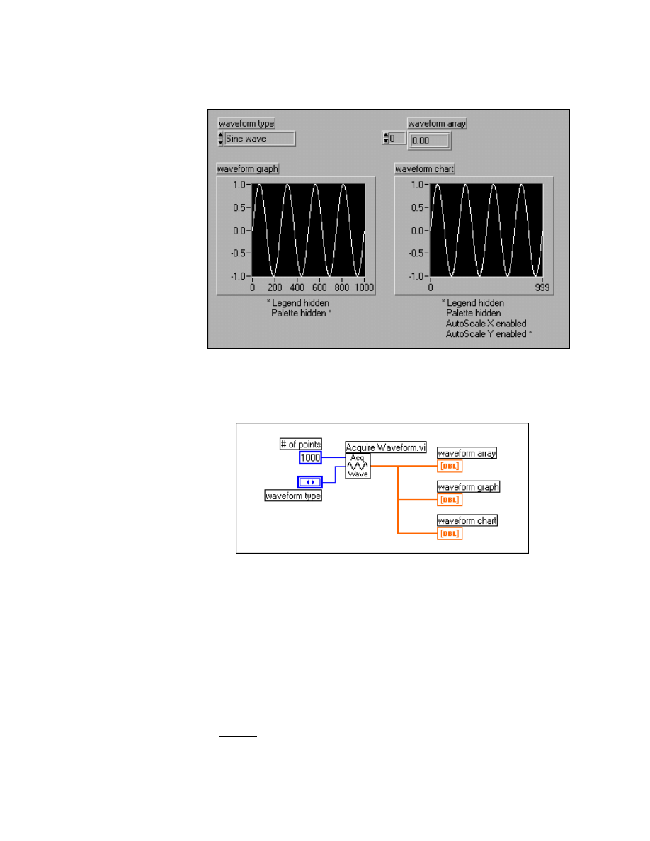
Module 1 Lesson 2 Exercises
©
National Instruments Corporation
1-2-3
LabVIEW Advanced I Course Manual
Front Panel
3. Go to the front panel and add the waveform chart as shown above.
Block Diagram
4. Return to the diagram and modify it as shown above.
5. Run the VI. Again choose Show VI Info… from the Windows menu
and now see how much memory each component uses. The data space
is now more than 40 KB. Here are where the data buffers are being
allocated:
8 KB - waveform array generated by the Acquire Waveform VI
8 KB - waveform array indicator on the front panel
8 KB - waveform graph on the front panel
8 KB - waveform array displayed on the waveform chart
+ 8 KB - waveform chart stores 1024 x 8 (DBL) bytes in the chart
40 KB
history

Module 1 Lesson 2 Exercises
LabVIEW Advanced I Course Manual
1-2-4
©
National Instruments Corporation
A total of 40 KB memory is used for all the data in the top-level VI. The
8 KB generated by the Acquire Waveform VI is execute data; the rest
is operate data.
The point of this part of the exercise is that you should not display large
data sets (particularly arrays, graphs, charts, and strings) on the front
panel unless you need to see that information. Otherwise, extra copies
of that data will use memory.
Part 2: Removing the Diagram
6. Save the VI into the
C:\Exercises\LV_AdvI\Mod1_mem.llb
library and name it Using Panel Memory.vi.
7. The block diagram usually is one of the larger components of memory
use. You will now take the block diagram out of memory.
8. Close the diagram window. Under the Operate menu, choose Change
to Run Mode. Select Show VI Info… from the Windows menu. The
diagram component should have a dash for memory use, indicating that
it no longer resides in memory.
9. Close the VI and any other open windows.
End of Exercise 2-1

Module 1 Lesson 2 Exercises
©
National Instruments Corporation
1-2-5
LabVIEW Advanced I Course Manual
Exercise 2-2
Objective:
To understand how the data space memory is allocated and buffers are reused.
1. Build each of the diagrams shown in this section of the lesson.
2. Run the VIs and check the memory use of each. Verify that the slides
give the correct values.
3. List two things that the LabVIEW application does to conserve
memory use.
______________________________________________________
______________________________________________________
4. List three basic rules of how a data buffer in memory is reused.
______________________________________________________
______________________________________________________
______________________________________________________
End of Exercise 2-2
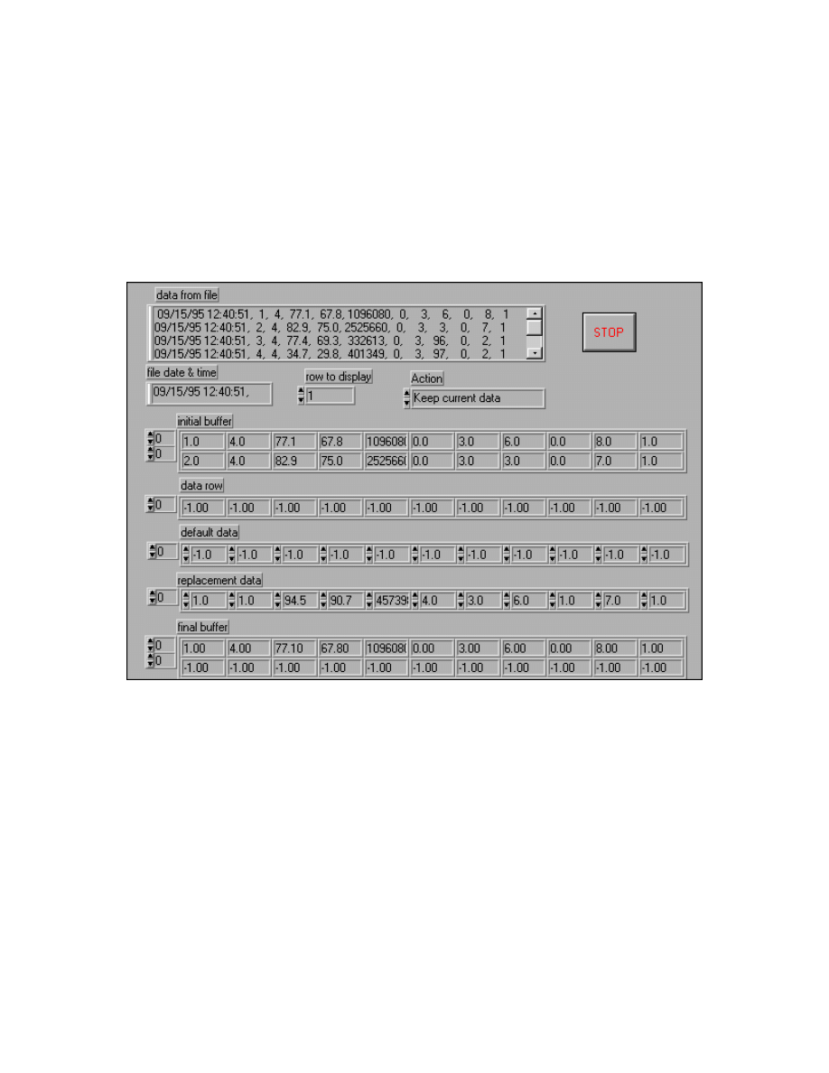
Module 1 Lesson 2 Exercises
LabVIEW Advanced I Course Manual
1-2-6
©
National Instruments Corporation
Exercise 2-3
Objective:
To use the concepts presented in this lesson to optimize memory usage in a VI.
You will open a VI that uses much more memory than the original
programmer expected. You will modify the VI to use memory more
efficiently, as per the information in this lesson.
Front Panel
1. Open the Using Memory VI from
mod1_mem.llb
and examine both
the panel and the diagram.
This VI reads a text file containing data. Then the file string is parsed
into the time and date string and a two-dimensional array of numbers.
You can then select any row out of this two-dimensional array and either
keep it or replace it with a default row or a row of values you define.
After you push the Stop button, the 2D array is reassembled with the
new values and you are prompted to write the data to a file in the same
format as the original file.
2. Run the VI. The file used for this exercise is
memfile.txt
, located in
the
C:\Exercises\LV_AdvI
directory. Change some of the rows in
the data file by selecting a particular action on a specified row of data.
Select the Stop button and type
newfile.txt
at the prompt.

Module 1 Lesson 2 Exercises
©
National Instruments Corporation
1-2-7
LabVIEW Advanced I Course Manual
3. Select Show VI Info… from the Windows menu and write the values
for each components memory use here:
Panel: ________________________
Diagram ______________________
Code: ________________________
Data: _________________________
Total: ________________________
4. Now you will modify this VI to use some of the memory optimizing tips
in this lesson. The following tips show the major things to change.
a. Notice that the diagram for this VI is larger than one screen. This is
one sign that the VI can be broken into subVIs. SubVIs can be
made for reading the data file and converting it to an array,
formatting and writing the array to file, and for replacing a row in a
two-dimensional array. Use the Create SubVI feature in the
LabVIEW Edit menu to create subVIs easily and quickly. (You can
use Revert under the File menu if you make a mistake.)
b. Remove front panel indicators and controls in the main VI that are
redundant or do not need to be displayed. Some controls and
indicators will not be needed when parts of the diagram are
converted to subVIs and intermediate buffers are eliminated.
c. Once you have created subVIs and made the program more modular,
you can modify each subVI to create the icon and connector pane.
d. Remove default data from front panel controls and indicators unless
the data is needed.
e. Remove the diagram from memory as you did in Exercise 2-1.
5. Return to the front panel and run the VI again. Choose Show VI Info…
from the Windows menu and now note the memory usage for each
component.
Panel: ________________________
Diagram _____________________
Code: ________________________
Data: ________________________
Total: ________________________
6. You can reduce the total memory use for this VI almost by a factor of
three by implementing the suggestions listed. Improvements like this
can be used for many VIs once you understand how LabVIEW allocates
memory for the various components and subVIs.
7. Close the VI and name it Using Memory (revised).vi.
End of Exercise 2-3

Module 1 Lesson 2 Exercises
LabVIEW Advanced I Course Manual
1-2-8
©
National Instruments Corporation
Additional Exercise
2-4
Create a VI that generates two arrays of random numbers with 1000
elements each. Add the two arrays together and display the result in
an array on the front panel. Name the VI Reusing Buffers.vi.
Run the VI and record the data space memory use here:
____________________.
Add a graph to the front panel and display the resulting array in it.
Run the VI again and record the data space memory use here:
____________________.
Create indicators to display both the random arrays before the Add
function. Run the VI and record the data space memory use here:
____________________.
Save all the indicator contents as the default by selecting Make
Current Values Default from the Operate menu. Note how this
changes the memory used by this VI.
_____________________________________________________
©
National Instruments Corporation
1-3-1
LabVIEW Advanced I Course Manual
Module 1
Lesson 3
Exercises
Exercise 3-1
Objective:
To modify a VI to use consistent data types for optimal memory usage.
You will open the Type Conversion VI and modify it to use memory more
efficiently by using smaller numeric representations and consistent data
types.
Front Panel
1. Open the Type Conversion VI from
C:\Exercises\LV_AdvI\mod1_mem.llb
.
2. Examine the front panel and the block diagram.
This VI generates 100 rows of sine waves and uniform white noise. The
sine waves and noise arrays are added together and scaled by
multiplying the result by 3.0. The average value for each row is
computed. The scaled noisy sine waves and the array of averages are
displayed.
3. Run the VI and select Show VI Info… from the Windows menu. Note
the data space memory size here:
_________________________
4. You will now modify this VI to remove coercion dots and convert the
numeric arrays to the smallest representation (SGL) to save data space
memory. Do not change the functionality of the VI, remove anything

Module 1 Lesson 3 Exercises
LabVIEW Advanced I Course Manual
1-3-2
©
National Instruments Corporation
from the panel, or change the number of samples generated. You should
be able to get the data space memory to less than 100 KB. Record your
optimized data space memory value here:
________________________
In general, be careful when you convert a VI to a different numeric
representation. If you plan to use any existing VIs or subVIs, many of
them use double-precision floats or 32-bit integers. If you try to reduce
memory use in one place by using a smaller numeric representation, you
actually may increase memory use due to inconsistent types.
5. Close the VI and name it Type Conversion (revised).vi.
End of Exercise 3-1
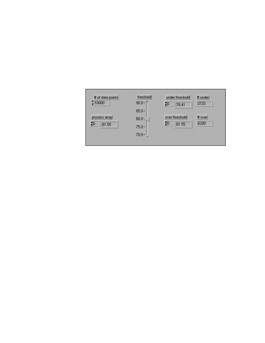
Module 1 Lesson 3 Exercises
©
National Instruments Corporation
1-3-3
LabVIEW Advanced I Course Manual
Exercise 3-2
Objective:
To build arrays efficiently.
You will modify a VI that takes an input array and creates two arrays from
the values over and under a user-specified threshold value to use memory
efficiently.
Front Panel
1. Open the Under/Over Threshold VI from
C:\Exercises\
LV_AdvI\mod1_mem.llb
. Open the diagram and examine how the VI
works.
This VI generates a waveform and displays it on the front panel. The
user selects a threshold value and the waveform is separated into two
waveforms, one consisting of values under the threshold value and the
other consisting of values over the threshold. The number of values over
and under the threshold are also displayed. Notice that the over and
under arrays start as empty arrays and are built one element at a time
with the Build Array function with each iteration of the loop. You
already know that this method is inefficient. Now you will monitor the
performance of this VI.
2. Select Show Profile Window from the Project menu. Make sure
Profile Memory Usage is not selected. This option slows down the VI,
and because memory management affects execution speed, you will just
monitor the timing statistics. Press the Start button and check the
Timing Statistics option.
3. Run the Under/Over Threshold VI several times and adjust the
threshold.
4. Return to the Profile Window and push the Snapshot button. Record the
average time it takes to run the Under/Over Threshold VI here:
_____________________
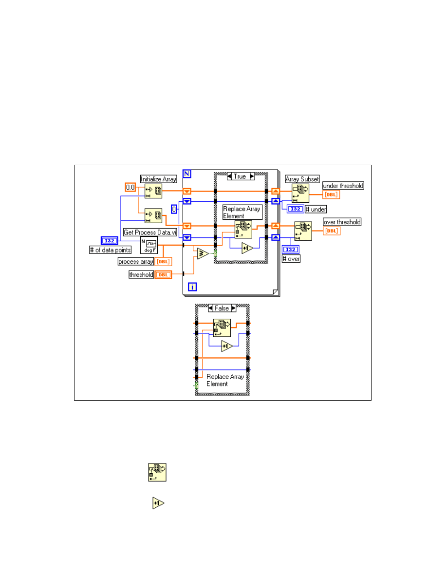
Module 1 Lesson 3 Exercises
LabVIEW Advanced I Course Manual
1-3-4
©
National Instruments Corporation
5. Select Show VI Info… from the Windows menu and record the data
space memory size here:
_____________________
6. Select Save As from the File menu and rename this VI Under/Over
Threshold (revised).vi. This assures that the original VI remains intact
as you make changes to the diagram. You will change how the over and
under arrays are generated to optimize memory use.
Block Diagram
1. Modify the block diagram to match the one shown above.
Remove the Build Array functions and the Array Size functions. Add
two more shift registers and initialize them to 0. Add the following
functions:
Replace Array Element function (Array palette). This
function replaces a new value into an array without allocating a
new buffer for the output.
Increment function (Numeric palette). In this exercise, this
function counts the number of values in the under and over
arrays.

Module 1 Lesson 3 Exercises
©
National Instruments Corporation
1-3-5
LabVIEW Advanced I Course Manual
Array Subset function (Array palette). In this exercise, this
function takes the subset of the under and over arrays that are
valid. Otherwise, the resulting over and under arrays would
have zeros at the end and contain 10,000 elements.
2. Save the VI.
3. Select Show Profile Window from the Project menu. Make sure
Profile Memory Usage is not selected. Press the Start button and check
the Timing Statistics option.
4. Run the Under/Over Threshold (revised) VI several times and adjust
the threshold.
5. Return to the Profile Window and push the Snapshot button. Record the
average time it takes to run the Under/Over Threshold VI here:
_____________________
6. Select Show VI Info… from the Windows menu and record the data
space memory size here:
_____________________
The revised VI runs faster than the original VI, although Show VI
Info… reports that the revised VI used more memory. This is because
Show VI Info… does not include the intermediate array buffers that are
generated, or the buffers that must be moved around in memory to make
them larger with the Build Array function. The revised VI shows that
even if you do not know how many elements a resulting data array
needs, you can allocate a larger buffer than you need, replace values into
that buffer, and then strip off the values you do not need after the
operation is finished.
If you are using a version of LabVIEW before 5.0, the difference
between the two VIs will be much greater because the Build Array never
reused memory buffers. Now that Build Array reuses memory buffers
when it can, its performance is much faster. The larger the array, the
more efficient the second VI will be in comparison with the first VI. The
Replace Array Element function will always be more efficient than the
Build Array function, but the difference will be smaller for smaller
arrays.
7. Close the Profile window and the Under/Over Threshold (revised) VI.
End of Exercise 3-2
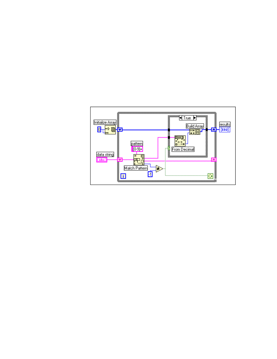
Module 1 Lesson 3 Exercises
LabVIEW Advanced I Course Manual
1-3-6
©
National Instruments Corporation
Exercise 3-3
Objective:
To examine two VIs parsing strings of data and their effect on memory use.
A common application is to read a string of data from file or an instrument
and then parse the useful information out of that string and display the
results. You can use the Match Pattern function to search a string for a
pattern. Depending on how you use it, you may decrease performance by
unnecessarily creating string data buffers.
Block Diagram
1. Open the Parsing Strings (part 1) VI from
C:\Exercises\
LV_AdvI\mod1_mem.llb
. The block diagram is shown above.
This is one method to find all integers in a string. The VI initially creates
an empty array, and then each time through the loop, searches the
remaining string for the numeric pattern. If the pattern is found (offset is
not -1), this diagram uses Build Array to add the number to a resulting
array of numbers. When there are no values left in the string, Match
Pattern returns -1 and this diagram completes execution.
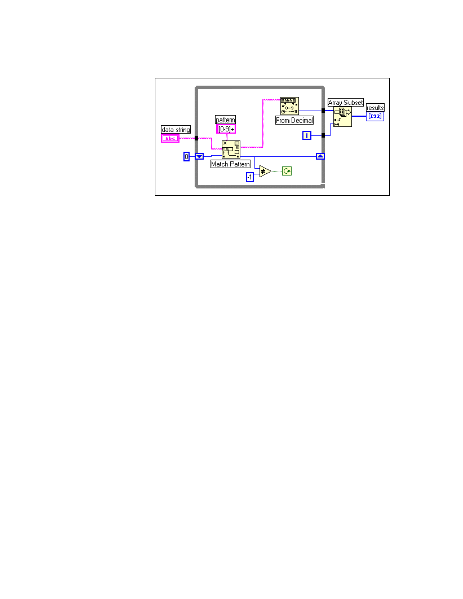
Module 1 Lesson 3 Exercises
©
National Instruments Corporation
1-3-7
LabVIEW Advanced I Course Manual
Block Diagram
2. Open the Parsing Strings (part 2) VI from
C:\Exercises\
LV_AdvI\mod1_mem.llb
. The block diagram is shown above.
This diagram fixes two problems the previous diagram displayed. One
problem with the first diagram is that it used Build Array in the loop to
concatenate the new value to the previous value. Instead, this diagram
uses auto-indexing to accumulate values on the edge of the loop. Notice
that you end up getting an extra, unwanted value in the array from the
last iteration of the loop where Match Pattern fails to find a match. A
solution is to use the Array Subset function to remove the extra
unwanted value.
The other problem with the previous diagram is that you create an
unnecessary copy of the remaining string every time through the loop.
Match Pattern has an input you can use to specify where to start
searching. If you remember the offset from the previous iteration with a
shift register on the loop, you can use this number to specify where to
start searching on the next iteration. Now you use only the one string
buffer in memory and no longer generate the intermediate strings.
3. Select Show Profile Window from the Project menu. Make sure
Profile Memory Usage is not selected. Press the Start button and check
the Timing Statistics option.
4. Run each VI several times. Return to the Profile Window and press the
Snapshot button. Record the average time it took to run the VIs here:
Parsing Strings (part 1) ___________________
Parsing Strings (part 2) ___________________

Module 1 Lesson 3 Exercises
LabVIEW Advanced I Course Manual
1-3-8
©
National Instruments Corporation
5. Select Show VI Info… from the Windows menu to compare the
memory usage of the VIs and record the total memory used by each
here:
Parsing Strings (part 1) ___________________
Parsing Strings (part 2) ___________________
The memory use reported by parts 1 and 2 is similar. However, the
second VI ran much faster because of the differences noted previously.
6. Close the Profile Window and both string parsing VIs.
End of Exercise 3-3
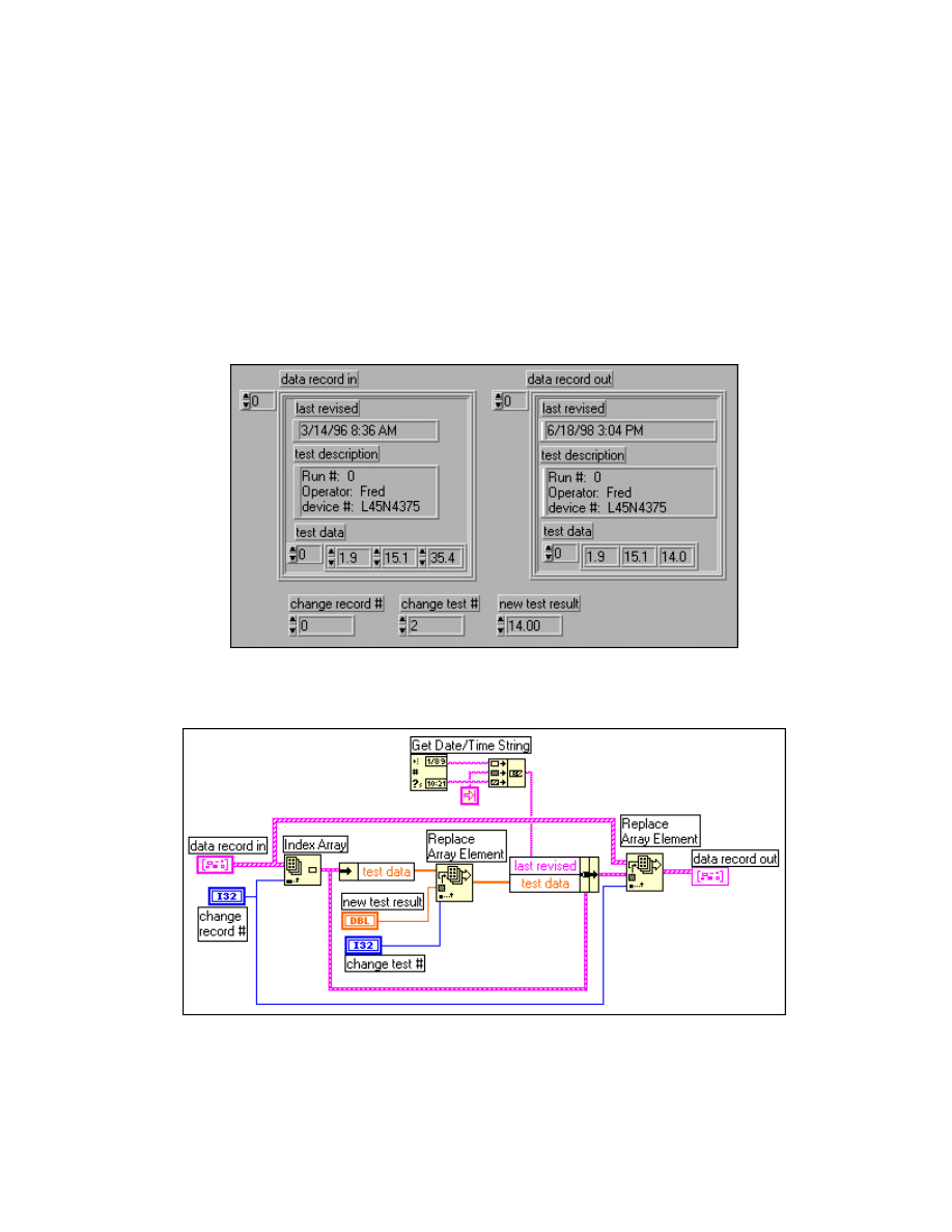
Module 1 Lesson 3 Exercises
©
National Instruments Corporation
1-3-9
LabVIEW Advanced I Course Manual
Exercise 3-4
Objective:
To examine how clusters use memory and how alternative data structures are more
efficient.
You will examine two VIs that perform operations on a mixture of different
data types. The difference will be in how the data is stored
—
one VI will use
a cluster to group the different data types, and the other will use more
efficient data types.
Front Panel
Block Diagram
1. Open the Using Complicated Data VI from
C:\Exercises\
LV_AdvI\mod1_mem.llb
. The panel and diagram are shown above.
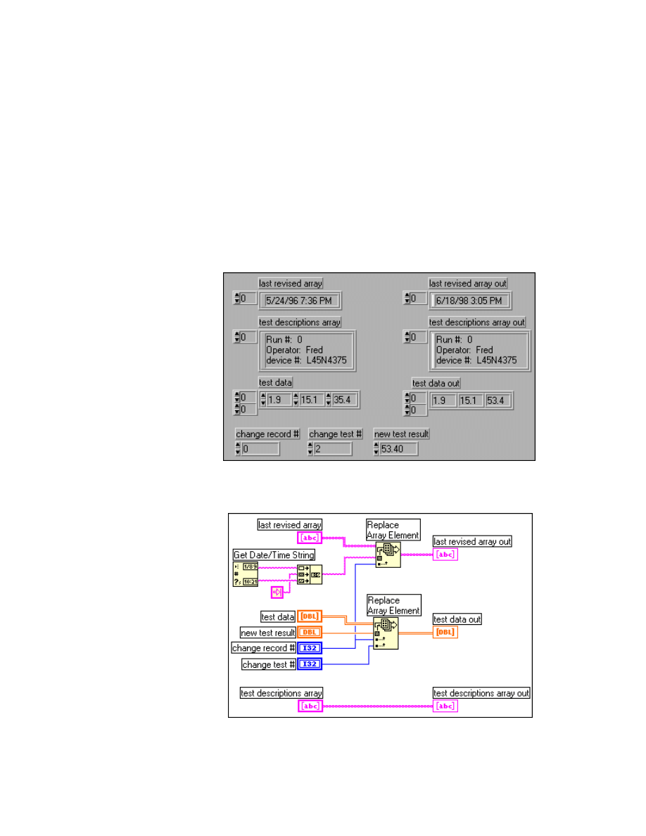
Module 1 Lesson 3 Exercises
LabVIEW Advanced I Course Manual
1-3-10
©
National Instruments Corporation
This VI has an array of clusters containing two strings and an array of
data. The purpose of the VI is to change one of the array values and log
the current date and time. This VI could be used inside a larger test
program for when a particular test is rerun and you want to replace the
old test result with the new value. To replace those elements in the array
of clusters, you must index and unbundle the elements. Each level of
unbundling/indexing may result in a copy of that data being generated
in memory. Notice that a copy is not necessarily generated. Copying
data is costly in terms of both time and memory when the data types are
large.
Front Panel
Block Diagram
2. Open the Using Efficient Data VI from
C:\Exercises\
LV_AdvI\mod1_mem.llb
. The panel and diagram are shown above.

Module 1 Lesson 3 Exercises
©
National Instruments Corporation
1-3-11
LabVIEW Advanced I Course Manual
This VI performs exactly the same operation on the same data as the
previous VI. However, to avoid extra copies that the
unbundling/indexing can cause, the data is stored in a different data
structure. The solution is to try to make the data structures as simple as
possible. In this case, you could break the data structure into three
arrays. The first array should be the array of strings for the date and time.
The second array can be the array of test descriptions. The third array
would be a two-dimensional array, where each row contains the results
for a given test. Notice you can now access or change any value in any
array with a single function and not copy the data.
You now will use the Profile Window to see if the changes in data
structure had an affect on memory or execution time.
3. Select Show Profile Window from the Project menu. Select the Profile
Memory Usage option. Press the Start button and check the Timing
Statistics and Memory Usage options.
4. Run both VIs several times. Return to the Profile Window and push the
Snapshot button. Record the average time it took to run the VIs and the
average memory used by the VIs here:
Average Time
Average Bytes
Using Complicated Data _______________
________________
Using Efficient Data
_______________
________________
5. Select Show VI Info… from the Windows menu to compare the
memory usage of the VIs and record the total memory used by each
here:
Using Complicated Data _______________
Using Efficient Data
_______________
6. The timing values reported by both VIs show that using efficient data
types is slightly faster than using complicated data types. Also, the VI
that used arrays of clusters used more memory than the VI that did not
use clusters. Considering these arrays had only 20 data records by
default, this shows that complicated data types can add overhead with
copies of data from unbundling and indexing large data components.
Also, remember that the reported memory values do not include the
handles and type descriptor headers used by the complicated data types.
7. Close the Profile Window and both VIs.
End of Exercise 3-4
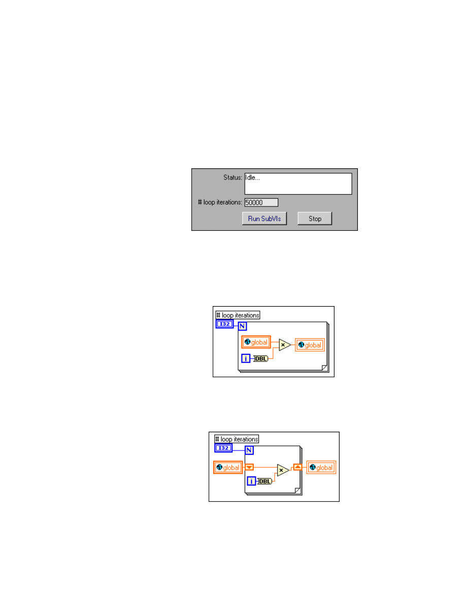
Module 1 Lesson 3 Exercises
LabVIEW Advanced I Course Manual
1-3-12
©
National Instruments Corporation
Exercise 3-5
Objective:
To examine the effect of overusing global variables inside loops.
You will use the Profile window to compare the performance of two VIs.
The first VI reads from and writes to a global variable for each iteration of
a loop. The second VI uses shift registers to temporarily store the data
between loop iterations.
Front Panel
1. Open the Global Benchmarks VI from
C:\Exercises\
LV_AdvI\mod1_mem.llb
.
This VI calls two subVIs. The first subVI reads from and writes to a
global variable inside a loop that executes 50,000 times as shown in the
diagram below:
The second subVI reads from a global once, stores the temporary values
in a shift register for the loop execution, and then writes to the global
once as shown in the diagram below:
You will now use the Profile Window to see how accessing global
variables unnecessarily will add to the execution time.

Module 1 Lesson 3 Exercises
©
National Instruments Corporation
1-3-13
LabVIEW Advanced I Course Manual
2. Select Show Profile Window from the Project menu. Press the Start
button and check the Timing Statistics option.
3. Run the Global Benchmarks VI and press the Run SubVIs button several
times. Return to the Profile Window and push the Snapshot button.
Record the average time it took to run the subVIs here:
Average Time
Update Globals Inside Loop ____________
Globals Outside Loop
____________
4. The timing values reported by both subVIs show that overusing global
variables can be much slower than using shift registers to store data. The
allocation for a copy of the global data each time a global variable is read
is the main reason for the slower performance. A small amount of
overhead (similar to accessing a subVI) is also associated with accessing
a global variable.
5. Close the Profile Window and the Global Benchmarks VI.
End of Exercise 3-5
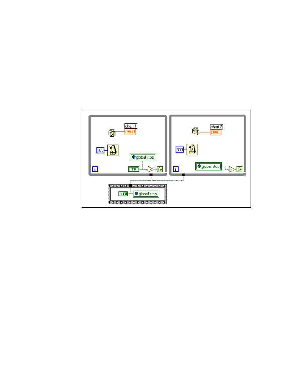
Module 1 Lesson 3 Exercises
LabVIEW Advanced I Course Manual
1-3-14
©
National Instruments Corporation
Exercise 3-6
Objective: To build a global variable using uninitialized shift registers.
You will examine two approaches for accessing a global Boolean. One VI
is already built with global variables and performs the action of stopping
multiple parallel loops. You will build a subVI that uses uninitialized shift
registers instead of global variables. Then you will rewrite the original VI to
use this new shift register global.
Block Diagram
1. Open the Accessing Globals VI from
mod1_mem.llb
. Examine the
diagram as shown above.
This VI contains two independent While Loops running at different
rates. Each loop generates a random number and displays that number
in a chart. When the user presses the Stop button, both loops end
execution through the use of a global variable.
2. Now you will build a global variable using an uninitialized shift register
inside a subVI.
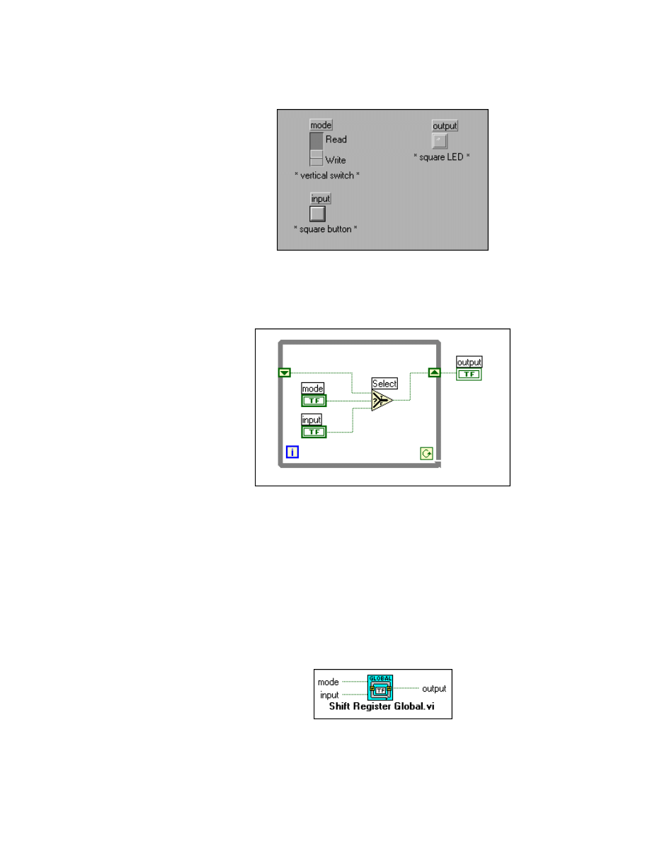
Module 1 Lesson 3 Exercises
©
National Instruments Corporation
1-3-15
LabVIEW Advanced I Course Manual
Front Panel
3. Open a new panel and build the panel shown above.
Block Diagram
4. Build the block diagram shown above.
Nothing is wired to the conditional terminal of the While Loop, so the
loop only executes once. The uninitialized shift register contains the last
value written to it. Mode determines whether you write a new value to
the global Boolean or you read the current value from the shift register.
As with built-in global variables, you must write a value to this shift
register global before you read from it. Otherwise, you may get an
unwanted value left over from the last time this shift register global was
called.
5. Make the icon and connector for the VI.
6. Save and close the VI. Name it Shift Register Global.vi.
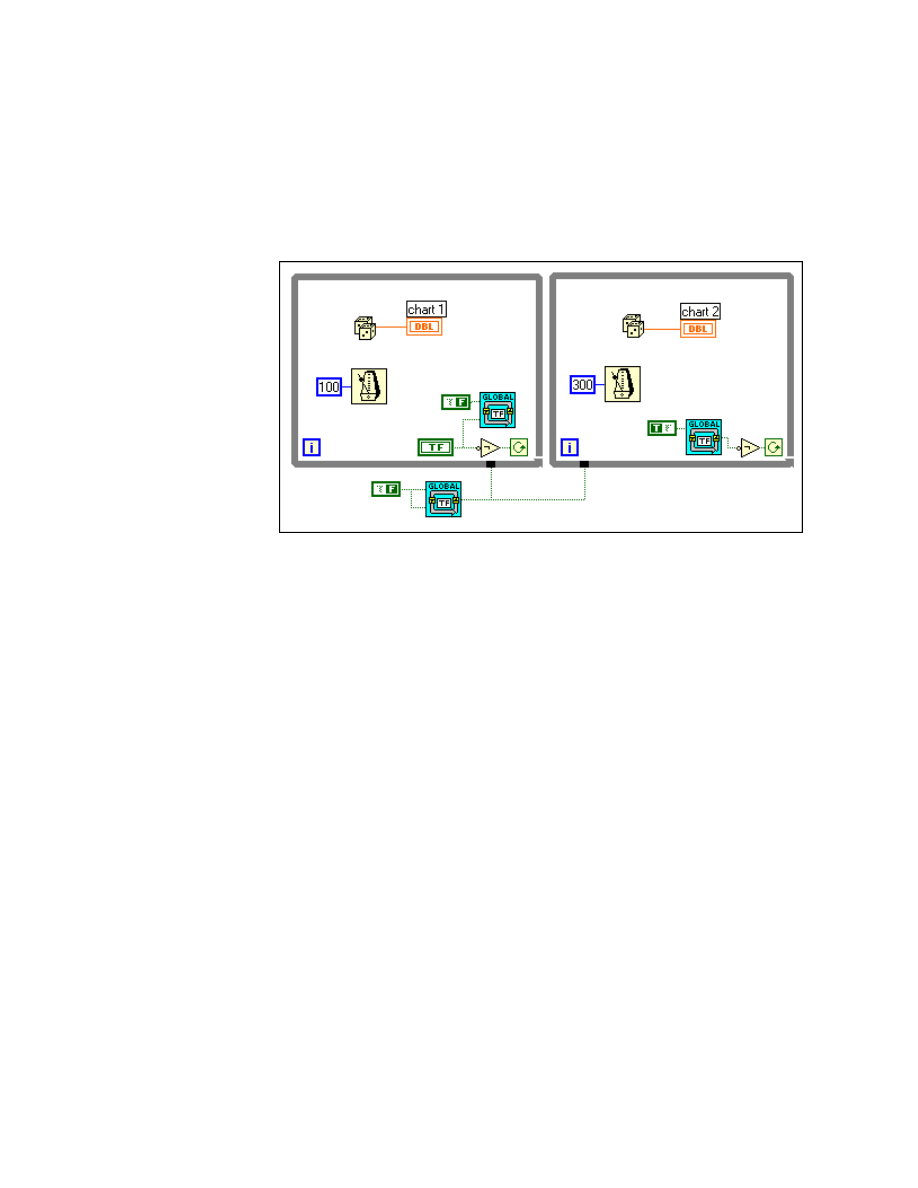
Module 1 Lesson 3 Exercises
LabVIEW Advanced I Course Manual
1-3-16
©
National Instruments Corporation
7. Return to the diagram for the Accessing Globals VI. Select Save As…
from the File menu and rename this VI Smarter Global.vi to avoid
overwriting the previous VI. You are now going to replace the global
variables with the shift register global you just created.
Block Diagram
8. Modify the block diagram as shown above. Remove all the global
variables, place Boolean constants where needed, and add three copies
of the Shift Register Global subVI.
9. Return to the front panel and run the VI. This VI performs the same
operations as the previous VI and has the same front panel. However,
instead of accessing a global variable, an “old style” global made from
an uninitialized shift register is used to store the Boolean.
You will not see any significant changes to the memory use between
these two examples because the global variable was a scalar Boolean.
However, in a situation where you are storing a global array or a global
cluster of arrays, the method used in the second VI uses memory more
efficiently because a new copy of the global variable is not made each
time the global is read. Shift registers reuse memory buffers. Also, when
all operations on shared data happen inside a subVI, the possibility of a
race condition is eliminated.
10. Save and close all open VIs.
End of Exercise 3-6
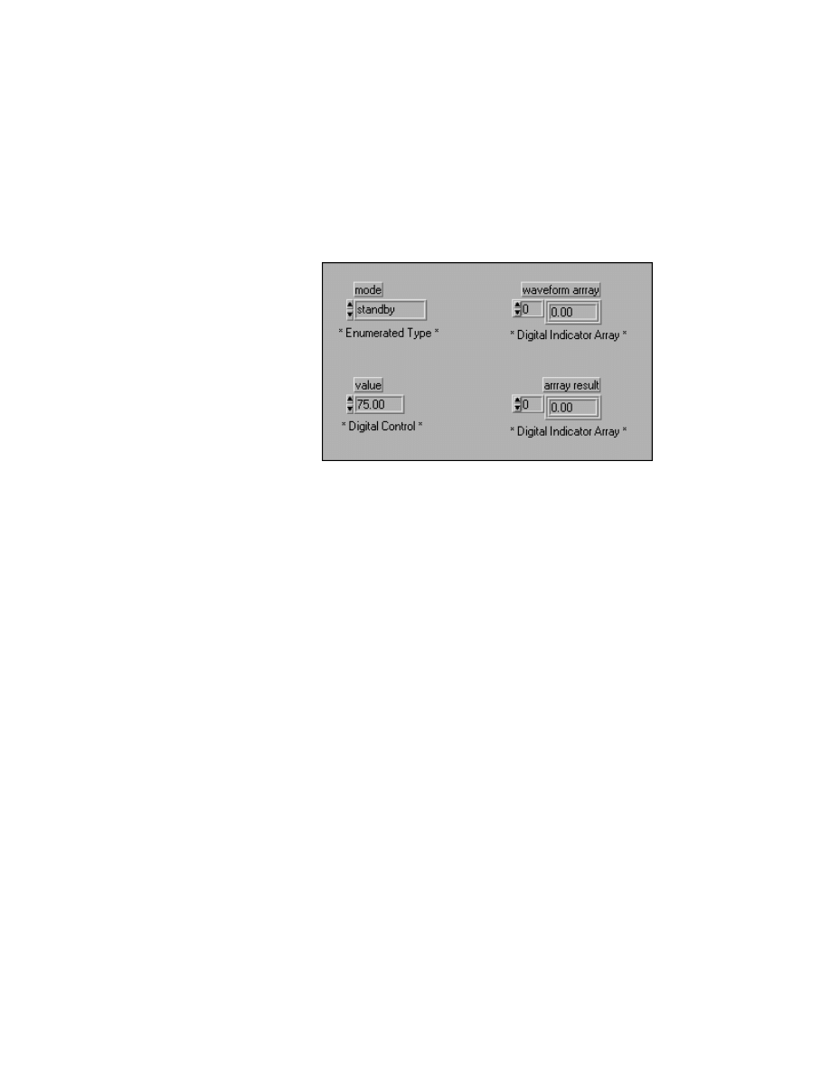
Module 1 Lesson 3 Exercises
©
National Instruments Corporation
1-3-17
LabVIEW Advanced I Course Manual
Exercise 3-7
Objective:
To examine how memory is used in a Case Structure.
You will create a VI that demonstrates how memory usage in a Case
structure changes depending on what that case is doing.
Front Panel
1. Open a new VI in LabVIEW and build the front panel shown above.
You get an Enumerated Type from the List & Ring palette. The
enumerated type control entries are entered by typing in the text and
then popping up on the control and selecting Add Item After from the
menu. The text entries and their order are:
0 – standby
1 – scale array
2 – empty array
3 – double array
When you create the two digital indicator arrays remember to first create
the array shell and then select a digital indicator and place it inside the
array shell.
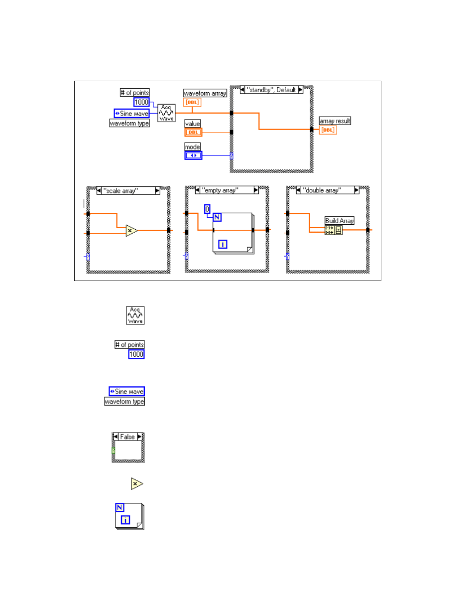
Module 1 Lesson 3 Exercises
LabVIEW Advanced I Course Manual
1-3-18
©
National Instruments Corporation
Block Diagram
1. Build the block diagram shown above.
Acquire Waveform VI (Select a VI… » C:\Exercises\
LV_AdvI\Mod1_mem.llb) generates a waveform of the type, length,
and scaling factor specified.
Numeric Constant (pop up on the # of points (top left) input of the
Acquire Waveform VI and select Create Constant from the menu)
specifies how many data points to generate for the waveform. Type in
the value of 1000 into the constant.
Enumerated Control (pop up on the waveform type input (middle
left) of the Acquire Waveform VI and select Create Constant from the
menu) specifies the type of waveform to generate. Use the Operating
tool to select Sine wave.
Case Structure (Structures palette) runs one of four different
operations depending on the front panel menu ring selection. Two cases
appear automatically; create the other two by popping up on the border
of the Case structure and select Add Case.
Multiply function (Numeric palette) scales the array by multiplying it
by a value.
For Loop structure (Structures palette) empties the array when N = 0.

Module 1 Lesson 3 Exercises
©
National Instruments Corporation
1-3-19
LabVIEW Advanced I Course Manual
Numeric Constant is created by popping up on the N of the For Loop
and selecting Create Constant from the menu; it is zero by default.
Build Array function (Array palette) doubles the waveform array by
concatenating a copy of itself and adding it to the end of the original
waveform array. Drag this function to include two inputs. Pop up on
each input and select Change to Array.
The Case structure selects one of four operations to perform on an array:
to do nothing, to multiply the array by a value, to empty the array, and
to double the size of the array. You will see what happens to the memory
used by this VI as you run each case in turn.
2. Save the VI as Case Structure Memory.vi.
3. Select Show VI Info… from the Windows menu and record the size of
the data space memory here:
____________________
4. Run this VI with mode set to standby. Select Show VI Info… from the
Windows menu and record the data memory use here:
____________________
5. Run this VI with mode set to scale array. Select Show VI Info… from
the Windows menu and record the data memory use here:
____________________
6. Run this VI with mode set to empty array. Select Show VI Info… from
the Windows menu and record the data memory use here:
____________________
7. Run this VI with mode set to double array. Select Show VI Info… from
the Windows menu and record the data memory use here:
____________________
You should notice that the memory use for the standby and scale array
cases are the same. The empty array case removes two copies of the
array buffer, and the double array case doubles the number of array
buffers used.
Sometimes the order in which you run a set of cases makes as much
difference as to what the cases actually do. Try running the VI again and
select the different modes in different order. Record any differences you
see compared with the memory use you observed previously.
If none of the cases can reuse data buffers from the input to the output,
an extra data buffer will exist. You can remove the extra buffer by

Module 1 Lesson 3 Exercises
LabVIEW Advanced I Course Manual
1-3-20
©
National Instruments Corporation
ensuring that one case (like the standby case in this exercise) reuses the
input buffer even if you never execute that case.
8. Close the VI when you are finished.
End of Exercise 3-7

Module 1 Lesson 3 Exercises
©
National Instruments Corporation
1-3-21
LabVIEW Advanced I Course Manual
Additional Exercises
3-8
Create a VI that generates a 1000-element array of random numbers
between 0 and 10 and then produces an array of all the values that
are over a threshold value chosen by the user. Use all the concepts
presented in this lesson to optimize this VI for memory use. Name
the VI Data Over Threshold.vi.
3-9
Create a VI that reads a data file called
logdata.txt
(in the course
exercises directory) and parses out the time and date, the number of
channels, the sampling rate, and displays the data in a graph. (Tip -
you will need to break down this project into stages.) First, read the
data file to understand the format. Then correctly parse out the
information of interest. Go over your VI one last time and optimize
it for memory use. Name the VI Getting Data.vi.
3-10
Select Search Examples... from the Help menu and go to the
Advanced » Execution Control section. Examine each of the
Synchronization Examples and make notes so you can tell the
difference between queues, notifiers, occurrences, rendezvous, and
semaphores. Also, make notes on how each of these synchronization
examples replaces global and local variables.

Module 1 Lesson 3 Exercises
LabVIEW Advanced I Course Manual
1-3-22
©
National Instruments Corporation
Notes
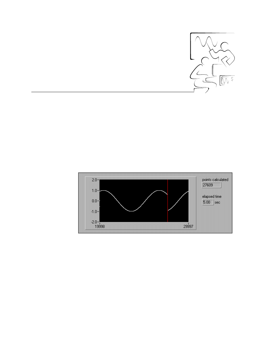
©
National Instruments Corporation
1-4-1
LabVIEW Advanced I Course Manual
Module 1
Lesson 4
Exercises
Exercise 4-1
Objective:
To examine the effect of enabling multithreaded execution for a simple VI.
You will open a VI that calculates and displays a sinusoid in a waveform
chart. The number of points calculated in five seconds is displayed. You will
compare the number of points calculated when the VI is run in a
single-threaded and in a multithreaded execution system.
Front Panel
1. Open the Thread Exercise VI from
C:\Exercises\LV_AdvI\
mod1_mem.llb
. Examine the panel and diagram.
This VI first clears the waveform chart and sets the number of points
calculated to zero. Then the While Loop calculates and displays a
sinusoid and shows the time elapsed for five seconds. The final number
of points calculated is displayed when the loop is finished.
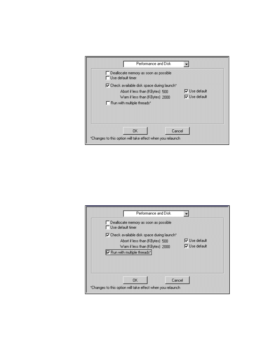
Module 1 Lesson 4 Exercises
LabVIEW Advanced I Course Manual
1-4-2
©
National Instruments Corporation
2. Verify that LabVIEW is currently running in single-threaded mode by
selecting Edit » Preferences » Performance and Disk and make sure
the Run with multiple threads option is unchecked as shown below:
If the “Run with multiple threads” box is selected, uncheck the box,
close all VIs, exit LabVIEW, and restart this exercise.
3. Run the VI several times and record the approximate number of points
calculated here:
____________________
4. Enable multithreading by selecting the Run with multiple threads
option in Edit » Preferences » Performance and Disk as shown below:
5. Close all VIs and exit LabVIEW.

Module 1 Lesson 4 Exercises
©
National Instruments Corporation
1-4-3
LabVIEW Advanced I Course Manual
6. Relaunch LabVIEW from the Start menu. Multithreading should now
be activated.
7. Open the Thread Exercise VI again from
mod1_mem.ll
b. Verify that
the Run with multiple threads option in Edit » Preferences »
Performance and Disk is still checked.
8. Run the VI several times and record the approximate number of points
calculated here:
____________________
Multithreading sped up the execution significantly for this VI. Updating
the elapsed time and chart indicators for each iteration of the While
Loop is a fairly slow task. With multithreading turned on, these tasks run
in the User Interface thread while the sine calculation and the While
Loop run in another thread. The diagram and the user interface are being
run asynchronously; that is, the chart and digital indicator are not
updated for each iteration of the loop anymore. This allows the Loop to
run several more iterations within the same five seconds.
9. Configure the waveform chart to show each data point generated in the
loop by popping up on the chart and selecting Synchronous Display
from the menu.
10. Run the VI several times and record the approximate number of points
calculated here:
____________________
11. Now that the chart is updated for each data value generated in the loop,
the increase in execution speed is now as slow as when the VI was
running in a single thread.
12. Sometimes you may notice that the indicators on the front panel of a VI
are not being updated properly. With multithreading, the user interface
is decoupled from the diagrams that create the data to display. So, for
example, if you are continuously acquiring data faster than you can plot
it, some data may be discarded by the user interface thread if it has
already been subsumed by new data. This allows the user interface to
“catch up” to what the diagram is doing. If it is important to see all of
the data, you can enable Synchronous Display on each indicator so the
diagram will wait for the panel to draw.
13. Close the VI when you are finished.
End of Exercise 4-1
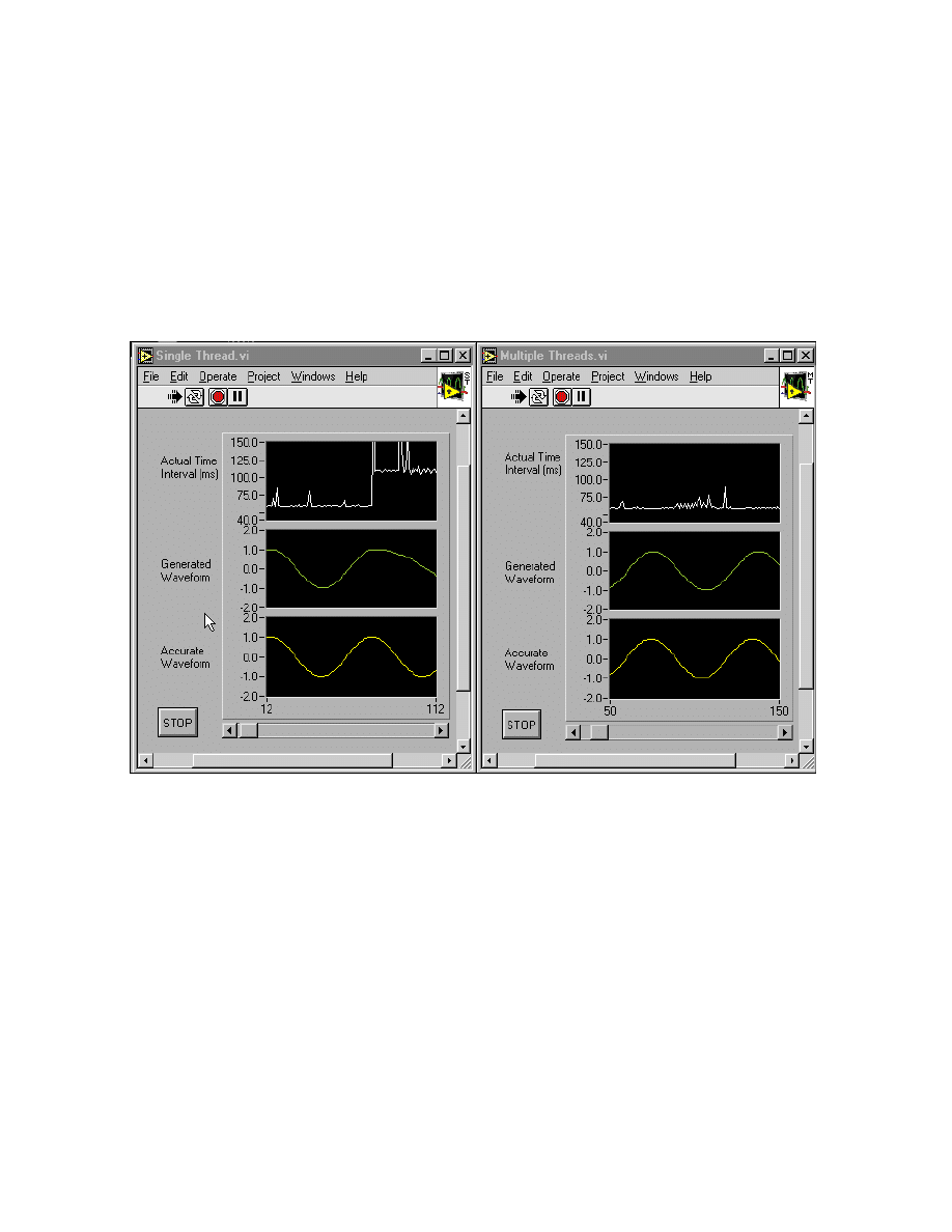
Module 1 Lesson 4 Exercises
LabVIEW Advanced I Course Manual
1-4-4
©
National Instruments Corporation
Exercise 4-2
Objective:
To show further effects of multithreading and how to make a VI run in a single thread
although the system is in multithreaded mode.
You will open two VIs that calculate and display a sinusoidal waveform in
a strip chart. One VI will run in a single thread and the other will run in
multiple threads as defined by LabVIEW.
Front Panels
1. Open the Single Thread and Multiple Threads VIs from
mod1_mem.llb
.
Examine the diagrams for these two VIs. The While Loop delay is set to
a fixed value of 60 ms. The top plot on the chart displays the actual loop
delay, the second chart display shows the generated sine wave based on
the actual loop delay, and the last chart display shows the sine wave
based on the desired loop delay.
The difference between the two VIs is that the Single Thread VI runs
completely in the user interface thread, while the Multiple Threads VI
runs in the standard execution system. You can double-check these
settings by popping up on the icon pane and selecting VI Setup »
Execution Options for each VI.

Module 1 Lesson 4 Exercises
©
National Instruments Corporation
1-4-5
LabVIEW Advanced I Course Manual
2. Run both VIs. You should see that each executes with an Actual Time
Interval close to 60 ms.
3. Select File » Open from either panel. The file dialog window will open.
Move the window so you can see the effect it has on the charts in
both VIs.
You should notice that the Actual Time Interval for the Single Thread
VI significantly increases, because it must share time with the file
dialog, mouse movements or clicks, keyboard selection, and any other
user interface operations. The Actual Time Interval for the Multiple
Threads VI increases slightly but still maintains a value close to 60 ms.
It is more deterministic because the diagram can execute independently
of user interface operations. The Multiple Threads VI is not completely
deterministic, because the operating system has to share the CPU among
the threads. Because Windows 95/NT/98 is not a real-time operating
system, there is no guarantee that the VI is deterministically scheduled.
4. Close the file dialog window by selecting Cancel.
5. Select other menu options and move and resize the various windows.
Note how each operation affects the actual time intervals for each
VI here:
______________________________________________________
______________________________________________________
______________________________________________________
6. Close any open windows when you are finished. Stop and close
both VIs.
End of Exercise 4-2
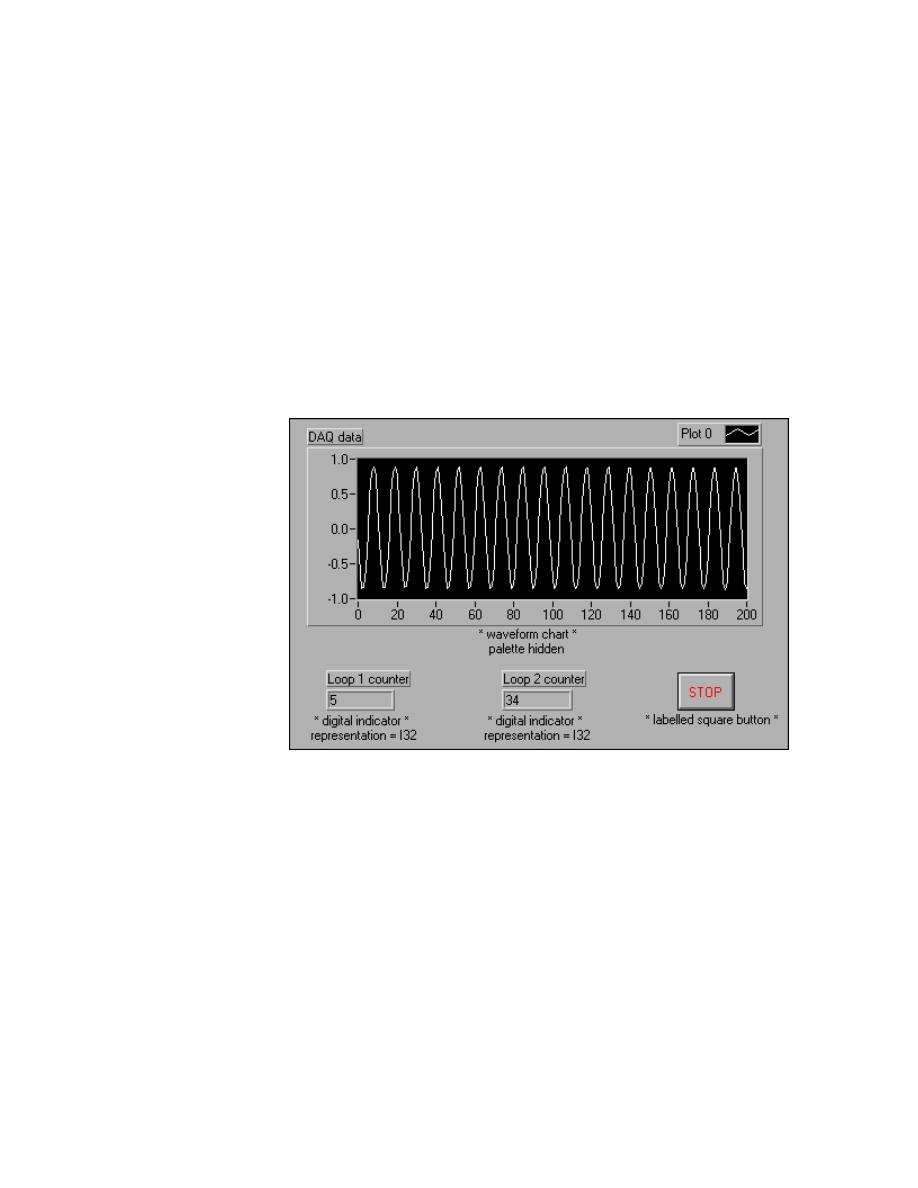
Module 1 Lesson 4 Exercises
LabVIEW Advanced I Course Manual
1-4-6
©
National Instruments Corporation
Exercise 4-3
Objective:
To build a VI that shows how multithreaded execution prevents one task from
interfering with another.
You will build a VI that reads data from a plug-in data acquisition (DAQ)
board and a DAQ Signal Accessory. The VI will have two loops in parallel.
The DAQ loop will acquire two seconds of data and then plot it to a graph.
The other loop executes four times per second and displays the loop
iteration.
Connect either the sine wave or the square wave to Analog Input Channel 1 on the
DAQ Signal Accessory.
Front Panel
1. Open a new VI and build the panel shown above.
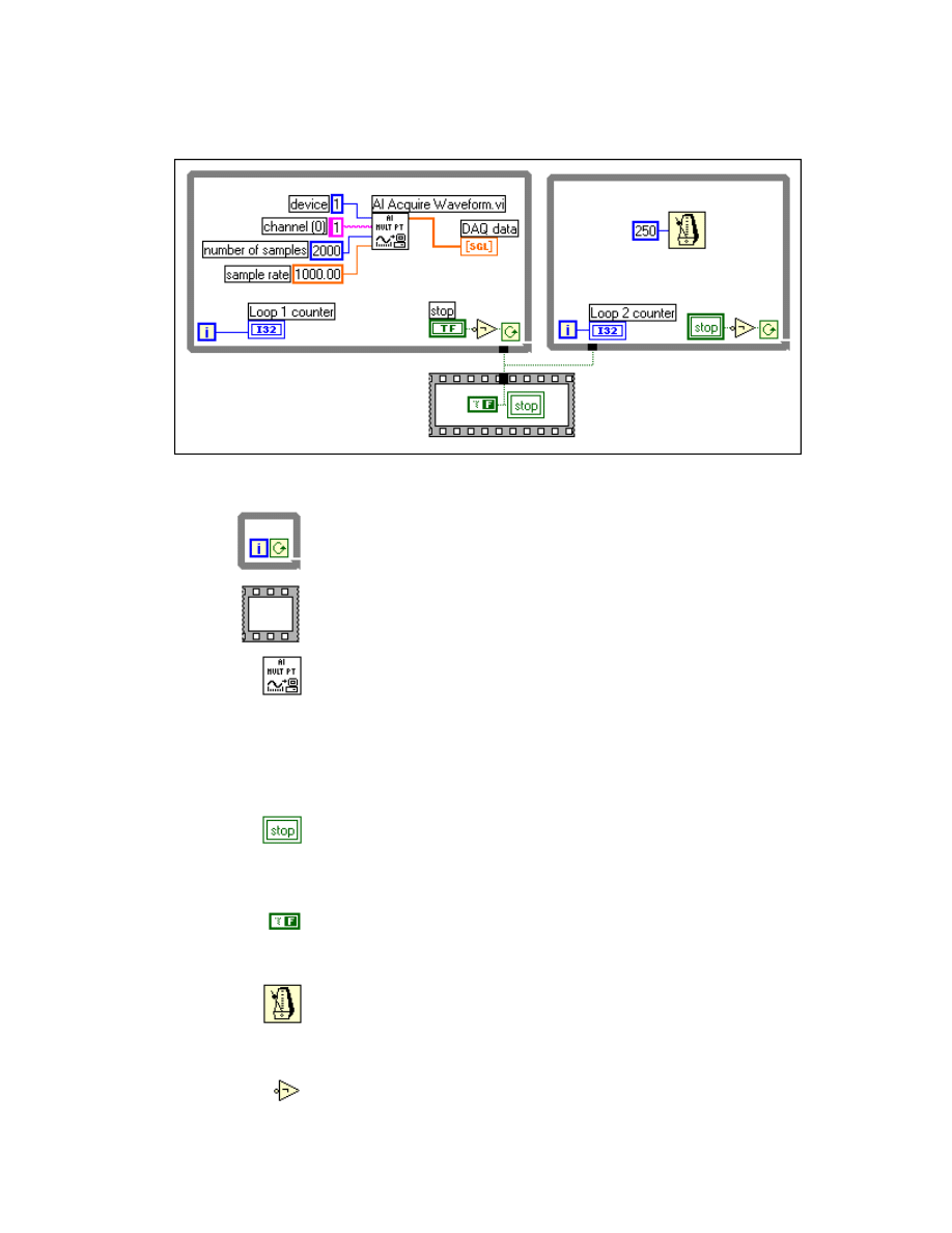
Module 1 Lesson 4 Exercises
©
National Instruments Corporation
1-4-7
LabVIEW Advanced I Course Manual
Block Diagram
2. Build the block diagram shown above.
While Loop structure (Structures palette) You will need two While
Loops. One performs DAQ and the other just displays the iteration
count.
Sequence structure (Structures palette). This structure initializes the
local variable for the stop button before the loops start.
AI Acquire Waveform (Data Acquisition » Analog Input palette).
This VI acquires the specified number of data values from the specified
board and channel at the specified sampling rate. Pop up on each of the
four left-hand-side input terminals and select Create Constant. You
will acquire data from device = 1 and channel = 1 for 2000 data values
at a sampling rate of 1000 Hz. This should acquire two seconds of data
from the DAQ board.
Local variable (pop up on the terminal for the Stop button and select
Create » Local from the menu). You will need to create two local
variables. Place one in the sequence structure. Pop up on the second one,
select Change To Read Local, and place it in the second While Loop.
Boolean constant (pop up on the write local inside the sequence and
select Create Constant from the menu). This constant initializes the
Stop button to False when the VI runs.
Wait Until Next ms Multiple function (Time & Dialog palette). This
function sets the second While Loop to execute every 250 ms. Pop up
on the input to this function and select Create Constant from the menu.
Type
250
into the resulting numeric constant.
Not function (Boolean palette). This function controls the While Loops.
When the Stop button is not pressed, the loops continue.

Module 1 Lesson 4 Exercises
LabVIEW Advanced I Course Manual
1-4-8
©
National Instruments Corporation
3. Save the VI as Multiple Tasks.vi.
4. Run this VI. You should see the waveform update every two seconds,
and the second loop counter should continue to count while the first loop
waits the two seconds to acquire the data and then display it. This is how
the VI works in a multithreaded environment.
5. Turn off multithreading by selecting Edit » Preferences »
Performance and Disk and unchecking the Run with multiple
threads option.
6. Stop and close the VI and exit LabVIEW.
7. Relaunch LabVIEW and open the Multiple Tasks VI.
8. Run the VI. Notice that this time, the second
loop counter does not
increment. When LabVIEW runs in a single thread, the CPU will sit idle
while the DAQ VI is acquiring two seconds of data. The operation of the
first loop is starving the second from getting any processor time.
9. You have learned from the LabVIEW Basics II course that if you put a
wait function inside the loop that is hogging all the system resources,
you can force the diagram to be asynchronous. Try this now by stopping
the VI and placing a wait function inside the first loop. You can set the
time interval to zero.
10. Run the VI again. Now you will see that the second loop runs in time
with the first loop. This is because the first loop is still holding the CPU
idle while the data is collected. The asynchronous wait function allows
the second loop to get one iteration completed before the first loop takes
over the CPU again.
Single-threaded tasks must run from a single queue, thus allowing any
one task to force the CPU to sit idle while waiting for a specified event.
Multithreaded execution uses the CPU more efficiently because it
allows multiple tasks to run independently within one application; if one
task needs to wait for an event, the other tasks can continue to execute.
11. Stop and close the VI when you are finished.
End of Exercise 4-3
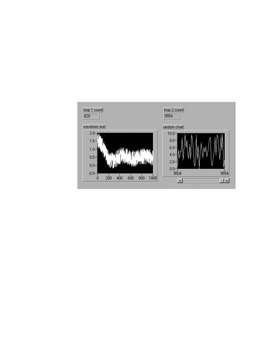
Module 1 Lesson 4 Exercises
©
National Instruments Corporation
1-4-9
LabVIEW Advanced I Course Manual
Exercise 4-4
Objective:
To examine the effect of two subVIs running in different threads with different
priorities.
You will open a VI that calculates and displays data from two different
subVIs. Each of these subVIs has a different execution system and different
priority. You will see how the performance of each subVI changes when
different threads and priorities are used.
Front Panel
1. Open the Thread Performance VI from
mod1_mem.llb
. Examine the
panel and diagram.
This VI contains two parallel While Loops. Each loop contains a subVI
that acquires data and plots that data. The first loop has a subVI that
generates 1000 data values and plots them in a waveform graph. The
second loop has a subVI that generates one value at a time and displays
it on a waveform chart. The loops run for five seconds each loop
iteration count is displayed.
You will now observe the changes in performance as this VI is run in
single-threaded mode and then as it is run in multithreaded mode with
the subVIs set for various different priorities and execution systems.
2. Verify that LabVIEW is currently running in single-threaded mode by
selecting Edit » Preferences » Performance and Disk and making sure
the Run in multiple threads box is unchecked.
3. Run the VI. Open Show VI Info… from the Windows menu and record
the total memory use here:
____________________

Module 1 Lesson 4 Exercises
LabVIEW Advanced I Course Manual
1-4-10
©
National Instruments Corporation
Record the loop iteration counts here:
Loop 1 count: ________________
Loop 2 count: ________________
Notice that LabVIEW will cooperatively multitask between the
different loops when it is in single-thread mode. Each subVI will get to
run for a specified amount of time. You could make one of the loops run
with lower priority by adding a wait function.
4. Set LabVIEW to run in multiple threads by selecting Edit »
Preferences » Performance and Disk and making sure the Run in
multiple threads box is checked. Close all open VIs and exit LabVIEW.
5. Relaunch LabVIEW and open the Thread Performance VI from
mod1_mem.llb
.
6. Open the diagram and record the priorities and execution systems for
both subVIs here. (Hint: Open VI Setup from the icon pane and look at
the Execution Options window.)
SubVI—Get Waveform SubVI—Get Random Data
Priority
___________________
_____________________
Execution
System
___________________
_____________________
7. Run the main VI. Open Show VI Info… and record the total memory
use here:
____________________
Record the loop iteration counts here:
Loop 1 count: ________________
Loop 2 count: ________________
8. Change the Priority for both subVIs to be Normal and change the
Preferred Execution System for both subVIs to be Standard.
9. Run the main VI. Record the loop iteration counts here:
Loop 1 count: ________________
Loop 2 count: ________________
Notice that changing the priorities and execution systems for the subVIs
can greatly affect how much CPU time each subVI is allocated. Watch
for situations like this if you run into performance problems in the
future.
10. Change the Priority for SubVI—Get Waveform to be time critical
priority (highest) and change the Preferred Execution System for that
subVI to be Data Acquisition.

Module 1 Lesson 4 Exercises
©
National Instruments Corporation
1-4-11
LabVIEW Advanced I Course Manual
11. Run the main VI. Record the loop iteration counts here:
Loop 1 count: ________________
Loop 2 count: ________________
Notice that when the first subVI is marked as highest priority, the second
subVI does not get to execute. This is how a high-priority thread can
starve lower priority threads from getting CPU time.
12. Close the VIs when you are finished. Do not save any changes.
End of Exercise 4-4

Module 1 Lesson 4 Exercises
LabVIEW Advanced I Course Manual
1-4-12
©
National Instruments Corporation
Notes
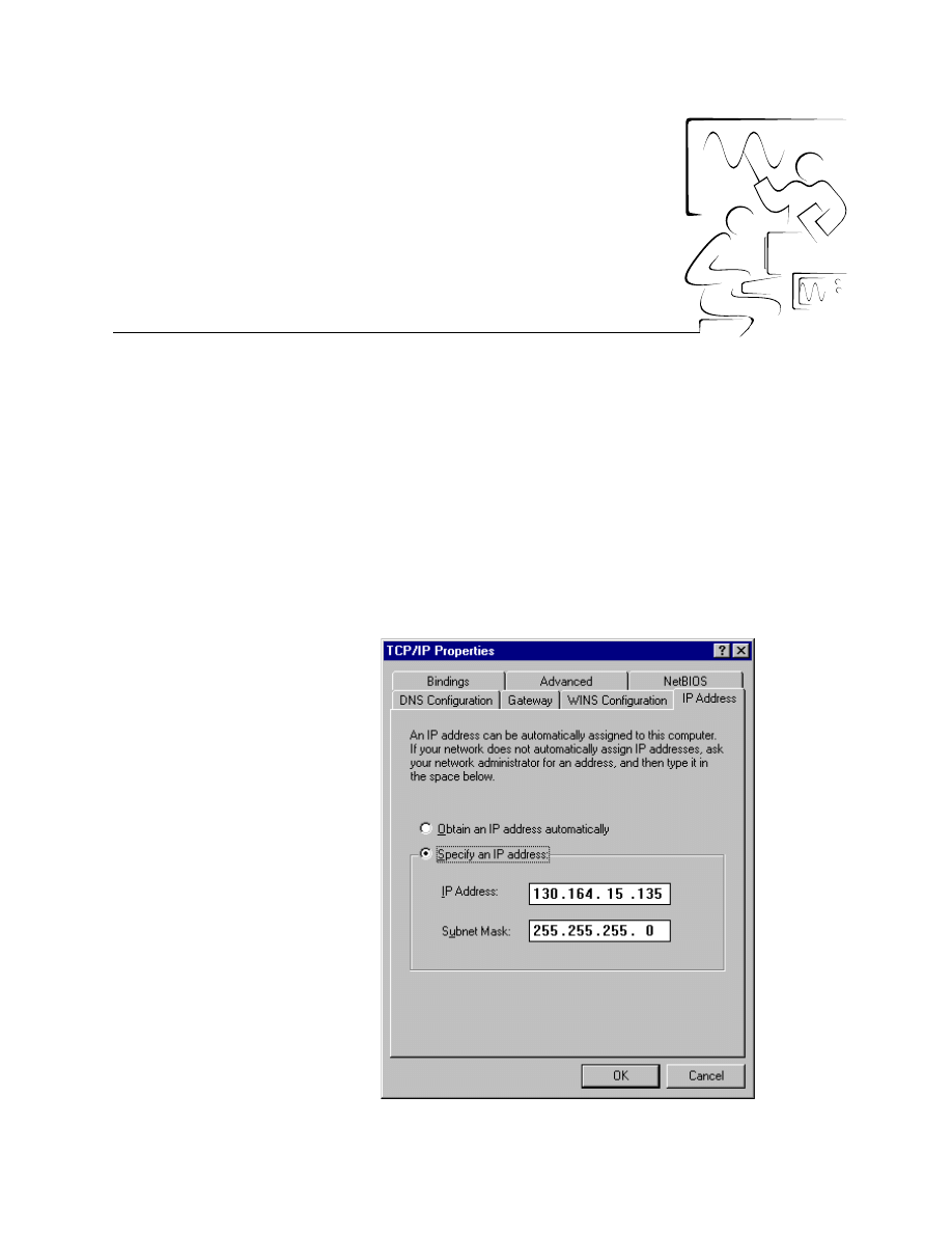
©
National Instruments Corporation
2-1-1
LabVIEW Advanced I Course Manual
Module 2
Lesson 1
Exercises
Exercise 1-1
Objective:
To determine the IP address for your computer.
You will examine some of the TCP/IP utilities on your computer to
determine your IP address.
1. From the Start option, select Settings » Control Panel » Network.
2. In the Configuration tab, you will see the list of network components
installed. Click to select TCP/IP and push the Properties button. The
following window will appear on the Windows 95 platform.

Module 2 Lesson 1 Exercises
LabVIEW Advanced I Course Manual
2-1-2
©
National Instruments Corporation
3. The seven tabs each describe the TCP/IP settings of your computer.
Enter your IP address here, as it may not match the one shown in the
previous graphic:
IP address: _________________________________
You will need this address later when communicating with other
computers. Go through the other tabs and observe the TCP/IP settings.
Depending on what kind of network communications you have enabled,
different tabs must be configured. This usually is done by your system
administrator. However, for this course, the computers are not
networked to a server and will be communicating peer-to-peer via
LabVIEW.
4. Close the TCP/IP properties windows by selecting the OK buttons.
None of the settings should have been changed, so you will not need to
reboot the computer.
End of Exercise 1-1
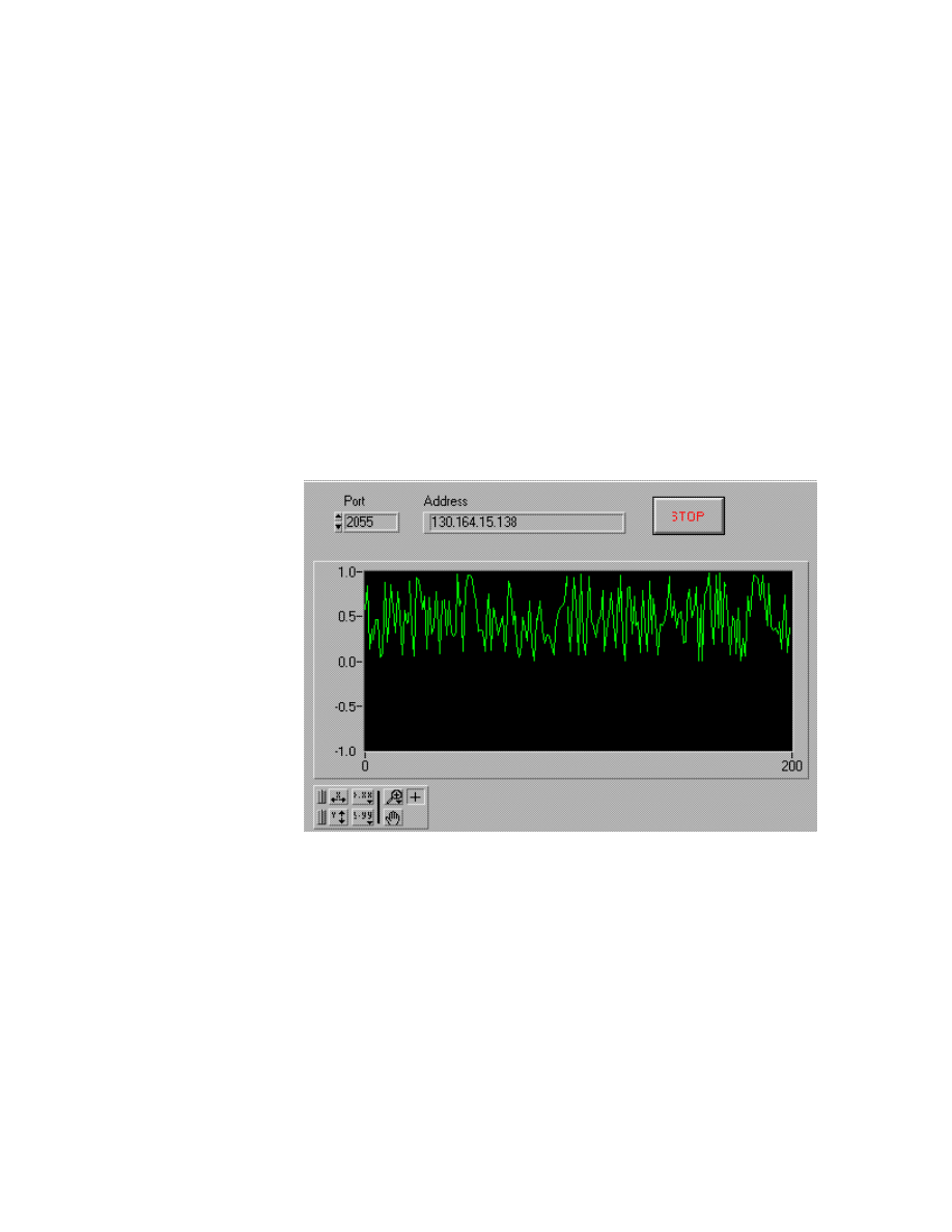
Module 2 Lesson 1 Exercises
©
National Instruments Corporation
2-1-3
LabVIEW Advanced I Course Manual
Exercise 1-2
Objective:
To examine a TCP Client VI and a TCP Server VI.
You will open two of the TCP/IP example VIs that show how LabVIEW can
be used as a TCP client and as a TCP server. If your computer is connected
to another through a network connection and you know the IP addresses or
hostnames of the computers, you can run this VI as described to see how the
TCP VIs/functions work.
Part 1—TCP Client
1. Select Open from the File menu and open the Simple Data Client VI
in
EXAMPLES\COMM\TCPEX.LLB
. The front panel and block diagram
are shown below.
Front Panel
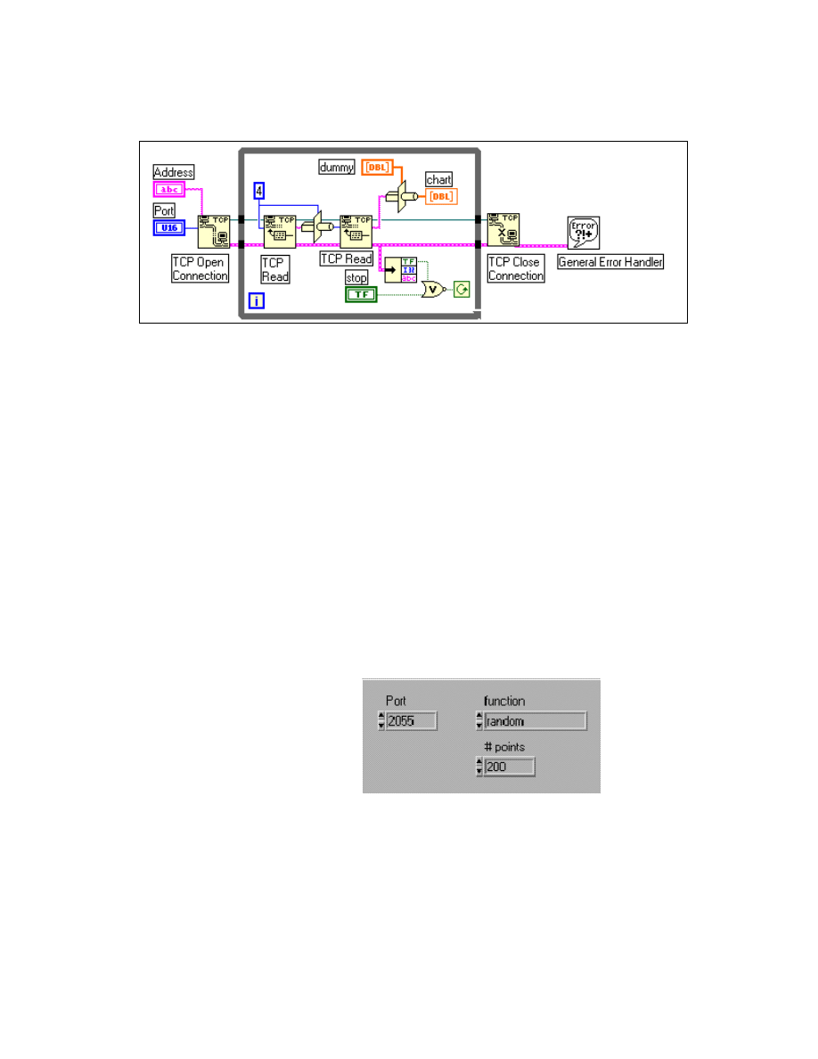
Module 2 Lesson 1 Exercises
LabVIEW Advanced I Course Manual
2-1-4
©
National Instruments Corporation
Block Diagram
2. Examine the block diagram shown above.
The TCP Open Connection function specifies which address and port
you should use to open the connection. Then the TCP Read function
reads four bytes of information. These four bytes are the size of the data
and are type cast to an I32 and used for the # of bytes to read on the
second TCP Read function. The resulting data is type cast to an array of
DBL (double-precision floats) and displayed in a chart. The TCP Read
functions are continuously called in a loop until either you press the
STOP button or an error occurs. In either situation, the TCP Close
Connection function stops the connection and errors are reported by the
General Error Handler VI.
Part 2—TCP Server
1. Select Open from the File menu and open the Simple Data Server VI
in
EXAMPLES\COMM\TCPEX.LLB
. The front panel and block diagram
are shown below.
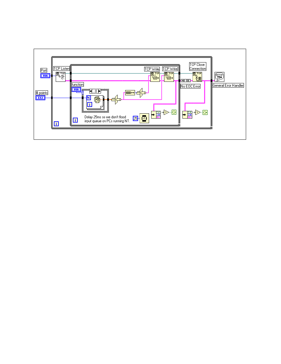
Module 2 Lesson 1 Exercises
©
National Instruments Corporation
2-1-5
LabVIEW Advanced I Course Manual
Block Diagram
1. Examine the block diagram above.
The TCP Listen VI will wait for a connection on the specified port
indefinitely (timeout = -1 or wait forever). Then, depending on the value
of function, either a random or sine waveform is generated and type cast
to a string. The length of that string is then type cast to a string and sent
to the client with the TCP Write function. A second TCP Write
function then sends the actual waveform string. Waveforms will
continue to be sent until an error occurs. If the error indicates that the
connection has been closed, as by the client VI, the error is reset and the
process of waiting for a connection on that port begins again. Also, there
is a delay of 25 ms in the loop so that you do not flood the input queue
on PCs running the Windows NT operating system.
The connection is terminated by the server in only two ways:
•
By an error other than the connection being closed by the client. An
example VI called No EOC Error.vi is used to check if the error is
a connection closed error.
•
By the user pressing the Abort Execution button in the toolbar.
2. If your computer is connected through TCP/IP to another computer that
has LabVIEW, and each computer has a unique IP address, you can run
the Simple Data Client on one computer and the Simple Data Server
on the other. You can run both the client and server VIs on the same
machine if your machine is not networked. Decide which computer will
be the server and make sure you know its IP address or hostname. Run
the Simple Data Server VI. Now run the Simple Data Client VI with
the server’s IP address or hostname. You should see the random or sine
waveform on the chart in the client VI as you change the Function ring
control on the server VI. To end the connection, press the STOP button

Module 2 Lesson 1 Exercises
LabVIEW Advanced I Course Manual
2-1-6
©
National Instruments Corporation
on the client VI. Stop the server VI by pressing the Abort Execution
button in the toolbar, because there is no other way to end its execution.
3. Close the Simple Data Client and Simple Data Server VIs. Do not
save any changes you may have made.
End of Exercise 1-2
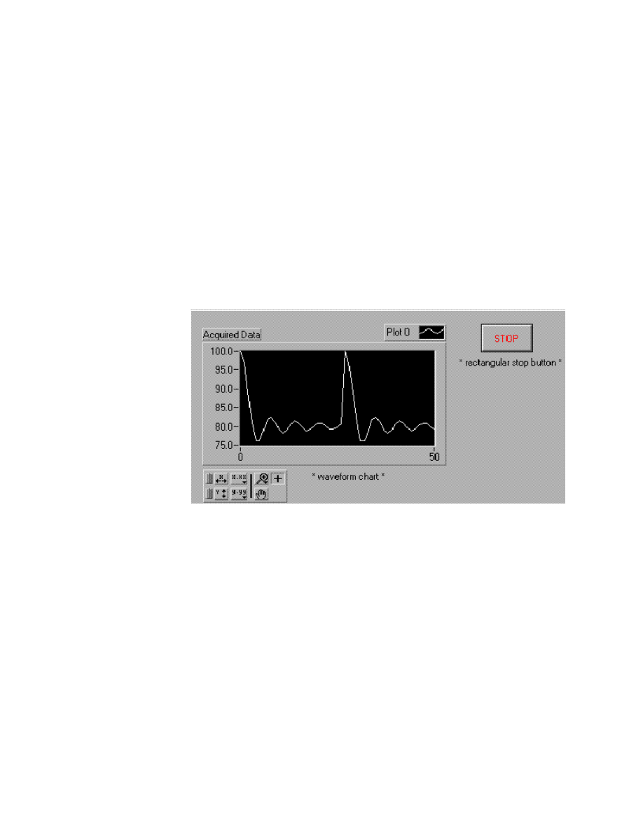
Module 2 Lesson 1 Exercises
©
National Instruments Corporation
2-1-7
LabVIEW Advanced I Course Manual
Exercise 1-3
Objective:
To build TCP client and server VIs that pass information back and forth.
You will build two VIs, one a TCP client and the other a TCP server. The
client VI will collect data and send that data and a time stamp to the server
VI. The server VI will accumulate the data and time stamp and display the
information on the front panel. When an error occurs or the user presses a
stop button on either VI, both VIs will close the connection, the server will
write the data to a file, and both VIs will stop execution.
1. Find a partner who has a computer connected to yours through TCP/IP
and decide which of you is the client and which is the server. You will
then build the corresponding VI as described below.
Client Front Panel
2. Select New from the File menu and build the panel shown above.
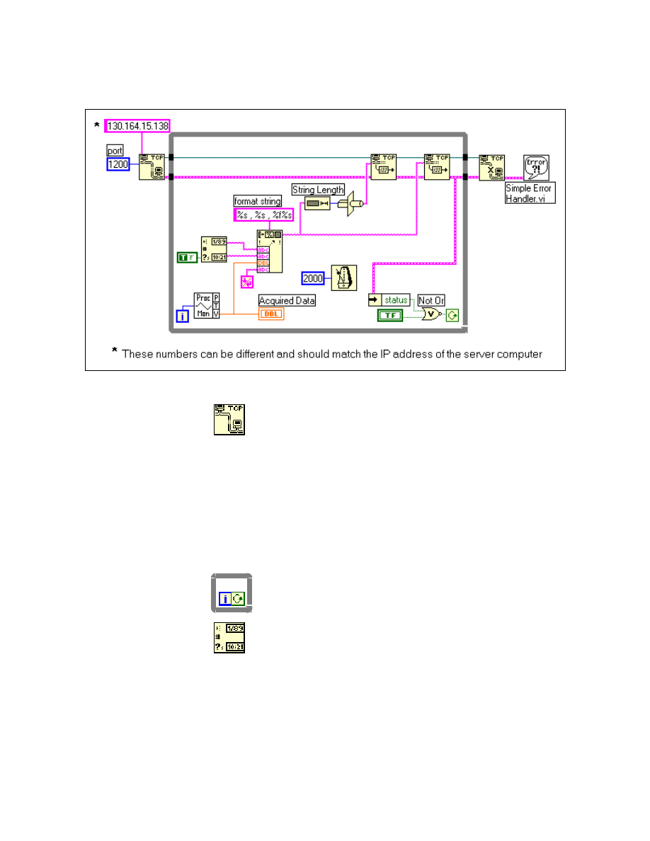
Module 2 Lesson 1 Exercises
LabVIEW Advanced I Course Manual
2-1-8
©
National Instruments Corporation
Client Block Diagram
3. Build the block diagram shown above.
TCP Open Connection function (Communication » TCP
palette). Opens the TCP communication with the other
computer. Once you have this function, get the Wiring tool.
Move the Wiring tool over the TCP Open Connection
function until the input says address, pop up on the function,
and choose Create Constant from the menu. Type the IP
address of the server obtained in Exercise 1-1 into this string
constant. Then move the Wiring tool down to the remote port
input, pop up again, and choose Create Constant from the
menu. Type the value of 1200 into the resulting numeric
constant.
While Loop structure (Structures palette). Used to
continuously run the VI until you press the STOP button or
until an error occurs.
Get Date/Time String function (Time & Dialog palette).
Returns the current date and time strings as specified by the
system clock of the PC. Get the Wiring tool and move it across
this function until it is over the want seconds? (F) input. Pop
up on the function and choose Create Constant from the
menu. Change the resulting Boolean constant to TRUE by
clicking on it with the Operating tool.
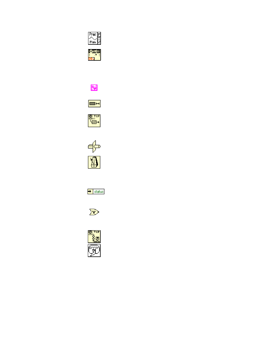
Module 2 Lesson 1 Exercises
©
National Instruments Corporation
2-1-9
LabVIEW Advanced I Course Manual
Process Monitor VI (Functions » Select a VI …) in
LV_AdvI\COMCLASS.llb
. Generates simulated data.
Format Into String function (String palette). Creates a string
that combines the time, date, and data value. You create the
format string by popping up on the function and choosing Edit
Format String from the menu. In the bottom of the window,
type
%s, %s, %f %s
and choose Create String.
End of Line constant (String palette). Places an end of line
character at the end of the formatted data string.
String Length function (String palette). Specifies the number
of characters in the formatted string.
TCP Write function (Communication » TCP palette). Writes
the data string to the other computer via TCP. You will need two
of these functions—one to send the byte count and the other for
the data string.
Type Cast function (Advanced » Data Manipulation palette).
Converts the byte count of the data string into a string format.
Wait Until Next ms Multiple function (Time & Dialog
palette). Controls the timing such that a new data string is
written every two seconds. Pop up on the input of this function
and choose Create Constant. Enter the value of 2000 into the
resulting numeric constant.
Unbundle By Name function (Cluster palette). Unbundles
the error status from the error cluster. If an error has occurred,
the loop will end and the TCP connection is closed.
Not Or function (Boolean palette). Tells the While Loop to
continue running if there is no error and the user has not pressed
the STOP button.
TCP Close Connection VI (Communication » TCP palette).
Closes the TCP communication on the port.
Simple Error Handler VI (Time & Dialog palette). Displays
a dialog box that reports any errors that have occurred.
4. Save this VI into
Exercises\LV_AdvI\COMCLASS.LLB
and name it
Acquire Data Client.vi.
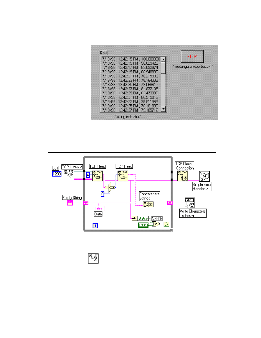
Module 2 Lesson 1 Exercises
LabVIEW Advanced I Course Manual
2-1-10
©
National Instruments Corporation
Server Front Panel
1. Select New from the File menu and build the panel shown.
Server Block Diagram
2. Build the block diagram shown above
TCP Listen VI (Communication » TCP palette). Listens on a
port for the client to make a connection. Move the Wiring tool
over the VI until the port input is highlighted. Pop up on the VI,
select Create Constant from the menu, and enter the value of
1200 into the resulting numeric constant.
Module 2 Lesson 1 Exercises
©
National Instruments Corporation
2-1-11
LabVIEW Advanced I Course Manual
While Loop structure (Structures palette). Continues to read
data from the client until either an error occurs or the user
presses the STOP button. Pop up on the loop boundary and
select Add Shift Register from the menu. This value will
hold the accumulated data string sent from the client.
TCP Read function (Communication » TCP palette). You
will need two of these functions. The first reads the byte count
from the client and the second reads the data string. On the first
TCP Read VI, pop up with the wiring tool on the bytes to read
input and choose Create Constant from the menu. Type the
value of
4
into the resulting numeric constant.
Type Cast function (Advanced » Data Manipulation
palette).Converts the byte count string into the original number.
Select a Numeric Constant from the Numeric palette and make
sure its representation is I32 so that the Type Cast will convert
the value to the correct representation.
Concatenate Strings function (String palette). Combines the
current data string with the accumulated string and stores it into
a shift register.
Empty String constant (String palette). Initializes the shift
register to an empty string.
Unbundle By Name function (Cluster palette). Unbundles
the error status from the error cluster. If an error has occurred,
the loop will end and the TCP connection is closed.
Not Or function (Boolean palette). Tells the While Loop to
continue running if there is no error and the user has not pressed
the STOP button.
TCP Close Connection function (Communication » TCP
palette). Closes the TCP communication on the port.
Simple Error Handler VI (Time & Dialog palette). Displays
a dialog box reporting any errors that have occurred.
Write Characters To File VI (File I/O palette). Writes the
accumulated data string to a file chosen by the user from a
dialog box.
3. Save this VI in
COMCLASS.LLB
and name it Acquire Data Server.vi.
4. Run the Acquire Data Server VI and then run the Acquire Data Client
VI. The string indicator in the front panel of the Acquire Data Server
VI should receive a new line of data every two seconds.
5. Continue to let the VIs run for a few more seconds and then press the
STOP button on either the client or the server panel. The other VI should
report an error that states a peer closed the connection. The server VI

Module 2 Lesson 1 Exercises
LabVIEW Advanced I Course Manual
2-1-12
©
National Instruments Corporation
also will show a dialog box asking the user to enter the filename in
which to save the data. Notice that you may not always want to show
TCP/IP error messages because in this case, you knew that the
connection had been terminated. Remember that in the previous
exercise, the Simple Data Server VI used the No EOC Error VI from
the Examples » Comm » TCPEX.LLB library to check if a connection
close error occurred and if so, reset the error to none. Therefore, you
may want to use this example VI to catch a closed connection error, or
log all the TCP errors to a file for the user to review at a later time.
6. Close both VIs.
End of Exercise 1-3
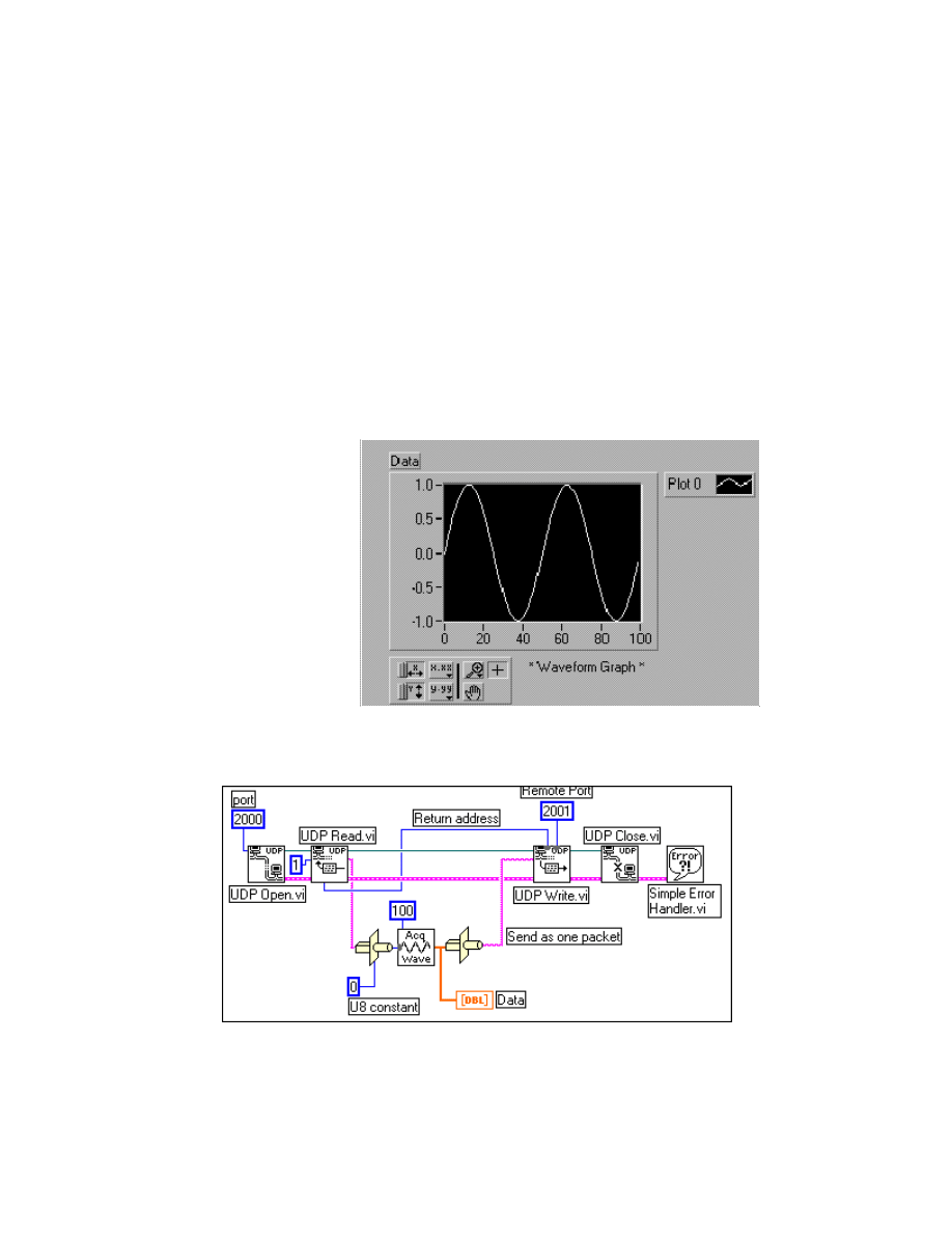
Module 2 Lesson 1 Exercises
©
National Instruments Corporation
2-1-13
LabVIEW Advanced I Course Manual
Exercise 1-4
Objective:
To use UDP to transfer data between VIs on different computers.
You will build two VIs, one to send waveform data through a UDP
connection and the other to receive data. The receiver VI will request the
waveform type and the sender VI will generate and send the appropriate
waveform over UDP. Both VIs will display the waveform in a graph on their
panels.
1. Get a partner who has a computer connected to your through TCP/IP and
decide which of you is the sender and receiver. Then you will build the
corresponding VI as described below.
Sender Front Panel
Sender Block Diagram
2. Open a new VI and build the front panel and block diagram shown
above.
Module 2 Lesson 1 Exercises
LabVIEW Advanced I Course Manual
2-1-14
©
National Instruments Corporation
UDP Open VI (Communication » UDP palette). Opens UDP
communication with the other computer on a given port. Move
the Wiring tool over the UDP Open VI until the input says port,
then pop up and choose Create Constant from the menu. Type
the value of
2000
into the resulting numeric constant.
UDP Read VI (Communication » UDP palette). Returns a
datagram that represents the type of waveform the computer is
requesting. Move the Wiring tool over this VI until the max size
(548) input is highlighted. Pop up, choose Create Constant
from the menu, type the value of
1
in the resulting numeric
constant.
Numeric Constant (Numeric palette). Specifies the type so you
can type cast the data from the UDP Read VI into the original
value that was sent. Pop up on this numeric and select the
unsigned byte integer (U8) from the Representation palette.
Type Cast function (Advanced » Data Manipulation palette).
You will need three Type Cast functions in this diagram for
converting data received and sent over the UDP connection.
Acquire Waveform VI (Functions » Select a VI…) in
LV_AdvI\COMCLASS.llb
. Generates a waveform array of the
type specified. Move the Wiring tool over this VI until the # of
points input is highlighted. Pop up on the VI and choose
Create Constant from the menu. Type the value of
100
into
the resulting numeric constant.
String Length function (String palette). Specifies the number
of characters in the waveform data string.
UDP Write VI (Communication » UDP palette). Writes the
data string to the other computer via UDP. You will need two of
these VIs—one to send the byte count and the other for the data
string. Be sure to wire the address and port values on these VIs.
UDP Close VI (Communication » UDP palette). Closes the
UDP connection.
Simple Error Handler VI (Time & Dialog palette). Displays
a dialog box reporting any errors that have occurred.
3. Save this VI into
COMCLASS.LLB
and name it UDP Send Data.vi.
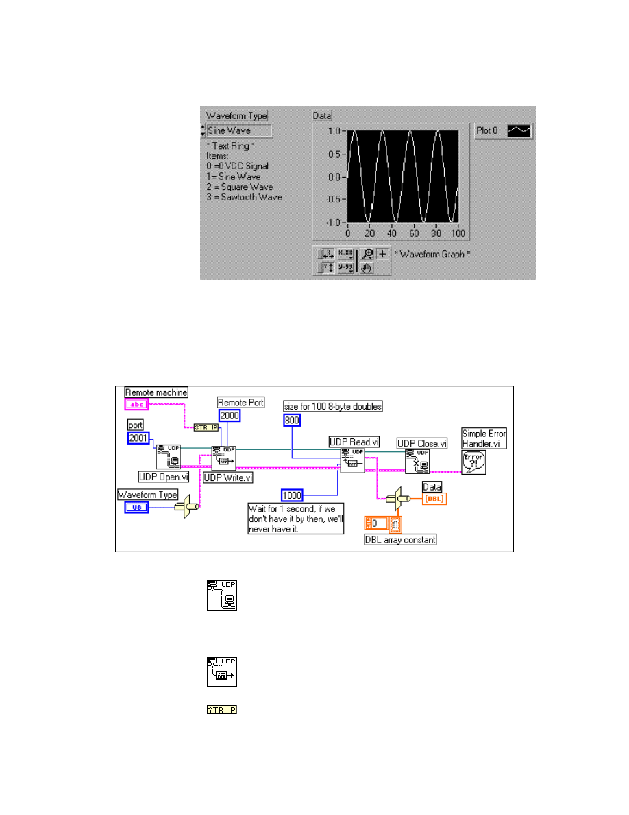
Module 2 Lesson 1 Exercises
©
National Instruments Corporation
2-1-15
LabVIEW Advanced I Course Manual
Receiver Front Panel
1. Select New from the File menu and build the panel shown above. The
Text Ring is located in the Controls » List & Ring palette. You create
the different menu items by popping up on the text ring and choosing
Add Item After for each new entry.
Receiver Block Diagram
2. Build the block diagram shown above.
UDP Open VI (Communication » UDP palette). Opens the
UDP communication with the other computer on a given port.
Move the Wiring tool over the UDP Open VI until the input
says port. Pop up and choose Create Constant from the menu.
Type the value of
2000
into the resulting numeric constant.
UDP Write VI (Communication » UDP palette). Writes the
data string specifying the waveform type to the other computer
via UDP.
String to IP function (Communications » TCP palette)
Converts a string to an IP network address.
Module 2 Lesson 1 Exercises
LabVIEW Advanced I Course Manual
2-1-16
©
National Instruments Corporation
Type Cast function (Advanced » Data Manipulation palette).
You will need three Type Cast functions. The first converts the
waveform type numeric to a string so the information can be
sent through the UDP connection. The second converts the byte
count from a string to a number, and the last one converts the
waveform string into and array of double-precision floats.
String Constant (String palette). Type the IP address (in dot
notation) of the computer with which you want to open the
UDP connection.
UDP Read VI (Communication » UDP palette). You will
need two of these VIs. The first one returns a datagram that
represents the size of the waveform and the second returns the
waveform string. Move the Wiring tool over the first UDP
Read VI until the max size (548) input is highlighted. Pop up,
choose Create Constant from the menu, and type the value of
4
into the resulting numeric constant.
Numeric Constant (Numeric palette). Specifies the type so you
can type cast the data from the UDP Read VI into the original
value that was sent. Pop up on this numeric and select the long
integer (I32) from the Representation palette. Create a second
Numeric Constant and change its representation to a double
precision (DBL).
Array Constant (Array palette). Specifies the type so you can
type cast the data from the UDP Read VI into the original data
sent. Place the DBL Numeric Constant created above inside the
array shell.
UDP Close VI (Communication » UDP palette). Closes the
UDP connection.
Simple Error Handler VI (Time & Dialog palette). Displays
a dialog box reporting any errors that have occurred.
3. Save this VI into
comclass.llb
and name it UDP Receive Data.vi.
4. If your machine is not networked, you can run both the VIs on the same
machine. Run the UDP Send Data VI first and then run the UDP
Receive Data VI. The waveform requested should appear on both
waveform graphs. Because these VIs do not contain loops, you run them
again to send another waveform across the UDP connection. You must
start the send VI first; otherwise, both VIs will receive timeout errors
because the receiver VI sends the waveform type information.
5. Close both VIs.
End of Exercise 1-4

Module 2 Lesson 1 Exercises
©
National Instruments Corporation
2-1-17
LabVIEW Advanced I Course Manual
Additional Exercises
1-5
Build two VIs for a TCP/IP application that sends data from one VI
to another. Name the VI that sends the data Sender.vi and name the
VI that reads data Receiver.vi. Both VIs should have a color box on
the front panel (Sender = control, Receiver = indicator). Your
Receiver should await the Sender to connect to its port and send one
piece of data. This data is the value of the color box on the Sender’s
front panel. Set the Receiver’s color box indicator to this same value.
Allow the VIs to continue passing data until the user presses a Stop
button on either front panel. Be sure to include error checking for all
TCP calls.
1-6
Modify the Acquire Data Server and Acquire Data Client VIs you
built in Exercise 1-3 to ignore the connection closed error, using the
No EOC Error VI in
EXAMPLES\COMM\TCPEX.LLB
. Rename the
VIs Revised Data Server and Revised Data Client.

Module 2 Lesson 1 Exercises
LabVIEW Advanced I Course Manual
2-1-18
©
National Instruments Corporation
Notes
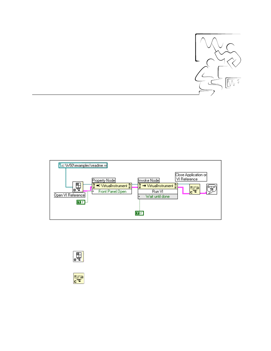
©
National Instruments Corporation
2-2-1
LabVIEW Advanced I Course Manual
Module 2
Lesson 2
Exercises
Exercise 2-1
Objective:
To build and run a VI to call another VI through the VI Server Interface.
You will build a LabVIEW VI to programmatically open and run a VI.
Block Diagram
1. Open a new VI in LabVIEW. Switch to the block diagram.
2. You will build the block diagram as shown in the figure above. Use the
following functions to complete your diagram.
Open VI Reference function (Application Control » Application
Control palette). Wire the path to readme.vi to the vipath input of the
Open VI Reference function.
Close Application or VI Reference function (Application Control »
Application Control palette). This function closes the VI Reference to
readme.vi.
Module 2 Lesson 2 Exercises
LabVIEW Advanced I Course Manual
2-2-2
©
National Instruments Corporation
Property Node function (Application Control » Application Control
palette). Wire the VI Reference to the Property Node function and then
pop up and select the Front Panel Window » Open property. The
appearance of the Property Node icon changes as shown at left.
Remember to pop up on the Property Node and choose Change to
Write.
Invoke Node function (Application Control » Application Control
palette). Wire the VI Reference to the Invoke Node function and choose
the Run Method. Also, wire a True Boolean to the “Wait Until Done”
parameter.
Simple Error Handler.vi (Time & Dialog palette).
Boolean constant (Boolean palette).
3. After you have finished, save the VI as Server Run VI.vi in
comclass.llb
.
4. Run the VI. This VI will open a reference to the Readme VI located in
the examples directory in the local version of LabVIEW. The front panel
of the VI is opened by accessing the Front Panel Open property of the
VI. Then the Run method runs the VI. Because Wait Until Done is
TRUE, this VI waits for the Readme VI to complete execution. After
exiting the Readme VI, the VI closes the VI Reference.
End of Exercise 2-1
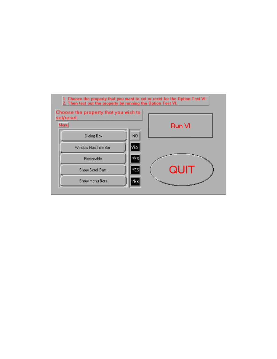
Module 2 Lesson 2 Exercises
©
National Instruments Corporation
2-2-3
LabVIEW Advanced I Course Manual
Exercise 2-2
Objective:
To complete and run a VI to set/reset properties of another VI through the VI Server
Interface.
You will complete a LabVIEW VI to programmatically set/reset some of its
properties and run the VI to test that the properties have been set or reset.
Front Panel
1. Open the Setting Window Options VI from
comclass.llb
. The front
panel of the VI is built for you and is shown above.
2. On the front panel is a menu cluster from which you can select the
property to set or reset. If the first time you click on a menu item the
property is set, the next time you click on the same menu button, the
property will be reset. The Run VI button runs the Open Test VI, whose
properties are being modified. This gives you chance to see how the
properties are being changed. There is also an LED corresponding to
each property on the front panel. The default values for the Option Test
VI properties are that it is not a dialog box, has a window title bar, is
resizeable, and displays scroll bars and menu bars. The LEDs indicate
whether a property is set or reset.
3. Switch to the block diagram. You will finish building this diagram.
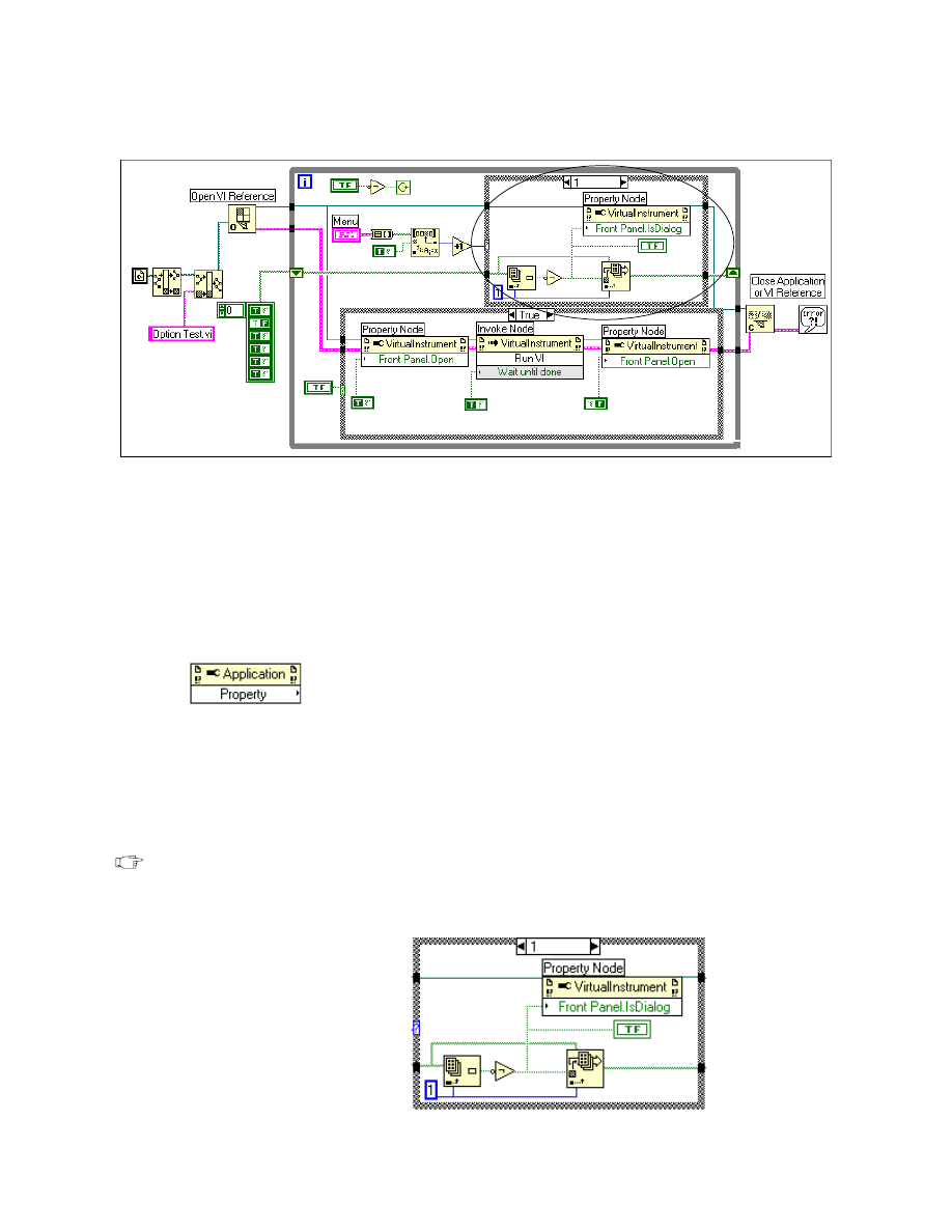
Module 2 Lesson 2 Exercises
LabVIEW Advanced I Course Manual
2-2-4
©
National Instruments Corporation
Block Diagram
4. In the block diagram, first you open a VI reference to the Option Test
VI from
comclass.llb
using the Open VI Reference function. This
VI reference refers to the local version of LabVIEW.
5. You will use the Boolean menu cluster to choose a property you would
like to set or reset. Depending on the property selected, the Property
Node will be used to set/reset the property.
6. You will complete the block diagram within the ellipse by inserting the
Property Node function in four cases of the case statement.
Property Node function (Application Control » Application Control
palette). In each case statement, select one of these nodes. Wire the VI
Reference to the reference input of the function.
Case 0: Empty
Case 1: Choose the property Is Dialog from the Property » Front
Panel Window pop-up menu. Pop up on the function and choose
Change to Write. Wire the output of the NOT to the property. Wire the
dup reference to the tunnel of the case statement as shown below.
Note
The IsDialog property of a VI prevents the user from interacting with other
LabVIEW VIs while the front panel is open, just as a system dialog box does.
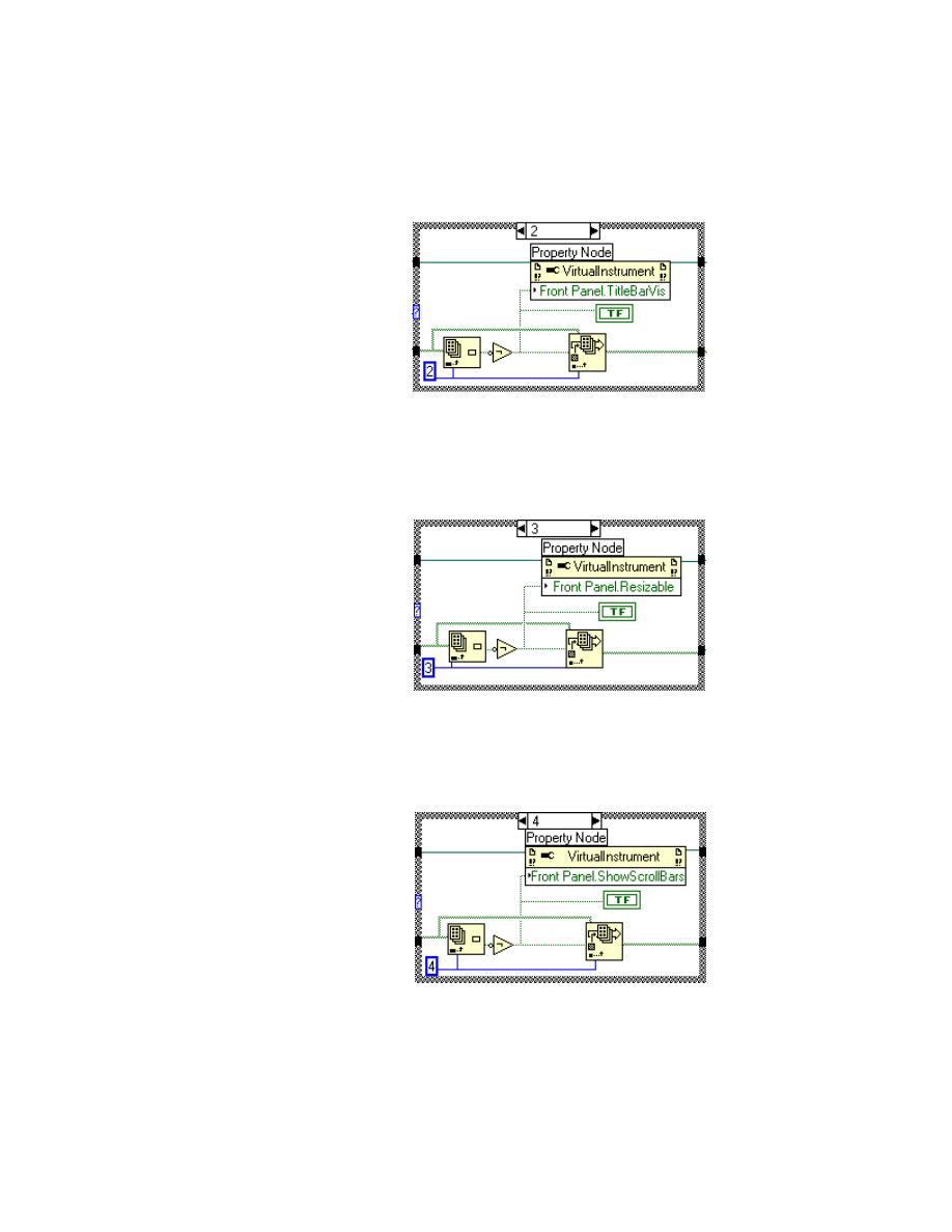
Module 2 Lesson 2 Exercises
©
National Instruments Corporation
2-2-5
LabVIEW Advanced I Course Manual
Case 2: Choose the property Title Bar Visible from the Property »
Front Panel Window pop-up menu. Pop up on the function and choose
Change to Write. Wire the output of the NOT to the property. Wire the
dup reference to the tunnel of the case statement as shown below.
Case 3: Choose the property Resizeable from the Property » Front
Panel Window pop-up menu. Pop up on the function and choose
Change to Write. Wire the output of the NOT to the property. Wire the
dup reference to the tunnel of the case statement as shown below.
Case 4: Choose the property Show Scroll Bars from the Property »
Front Panel Window pop-up menu. Pop up on the function and choose
Change to Write. Wire the output of the NOT to the property. Wire the
dup reference to the tunnel of the case statement as shown below.
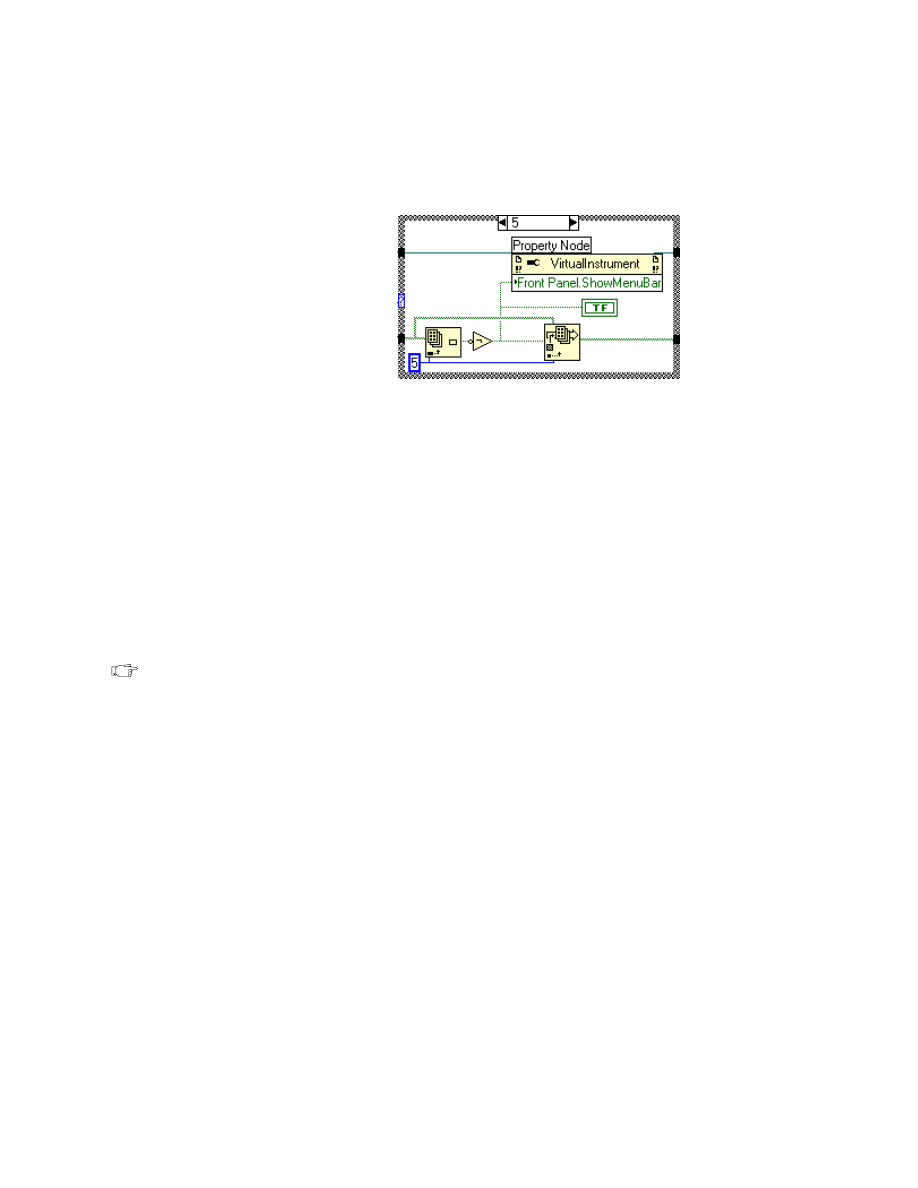
Module 2 Lesson 2 Exercises
LabVIEW Advanced I Course Manual
2-2-6
©
National Instruments Corporation
Case 5: Choose the property Show Menu Bars from the Property »
Front Panel Window pop-up menu. Pop up on the function and choose
Change to Write. Wire the output of the NOT to the property. Wire the
dup reference to the tunnel of the case statement as shown adjacently.
7. After you finish building the block diagram, save the VI.
8. The Run VI button is used to open the front panel of the Option Test VI
by using the Property Node function. Then the Invoke Node function
runs the VI, and the front panel of the VI is closed by wiring a FALSE
to the Property Node function’s Front Panel Open property.
9. Finally, the Close Reference function closes the Application reference
and the VI reference.
10. Switch to the front panel and run the VI. Select each property at least
twice to check that all the properties are being correctly set/reset. After
you click on a property, verify it by running the Option Test VI. Try all
the properties. Press the QUIT button to stop the VI.
Note
Make sure that you close the Option Test VI by clicking on OK on its front
panel before setting or resetting the next property.
11. After you are done, close the VI.
End of Exercise 2-2
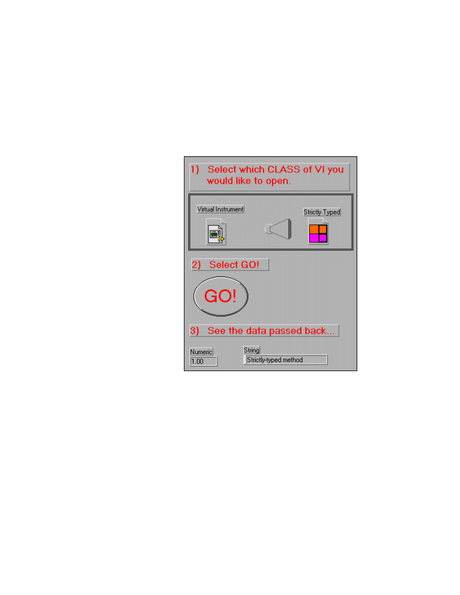
Module 2 Lesson 2 Exercises
©
National Instruments Corporation
2-2-7
LabVIEW Advanced I Course Manual
Exercise 2-3
Objective:
To complete and run a VI that demonstrates the difference between a strictly typed
reference and a plain VI reference.
You will complete a LabVIEW VI which demonstrates how to call strictly
typed and virtual instrument class VIs using the VI server.
Front Panel
1. Open the Strictly Versus VI Reference VI from
comclass.llb
.
2. The completed front panel of the VI is shown above. You will complete
the front panel of this VI by selecting the strictly typed and Virtual
Instrument Reference.
3. Select Application or VI Reference from the Controls » Path &
Refnum menu. Place this reference below the Strictly Typed label. Pop
up on the reference and select VI Server Class... » Browse. Browse for
the Pop Up VI in
comclass.llb
and select OK. The refnum will take
the connector pane of the Pop Up VI.
4. Next, create a Virtual Instrument refnum below the specified label by
choosing the Application or VI Refnum from the Controls » Path &
Refnum menu. Pop up and select the VI Server class to be Virtual
Instrument.
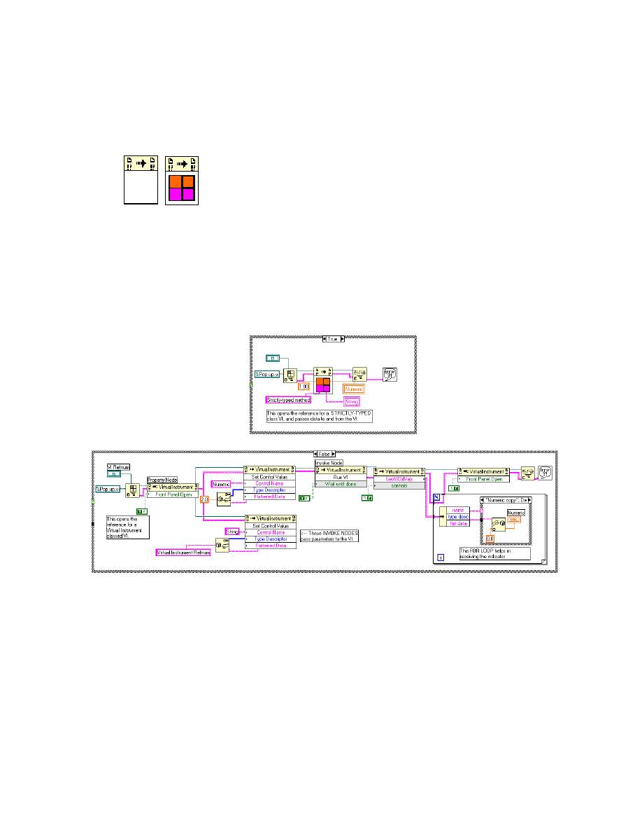
Module 2 Lesson 2 Exercises
LabVIEW Advanced I Course Manual
2-2-8
©
National Instruments Corporation
5. Switch to the block diagram. Connect the VI reference to the Open VI
Reference function in the FALSE case. Connect the strictly typed
reference to the Open VI Reference function in the TRUE case. Next,
place the Call by Reference function on the block diagram by following
the instructions below.
Call By Reference function (Application Control » Application
Control palette). Wire the VI Reference to the Reference input of the
function. The function will take the connector pane of the Pop Up VI as
shown at left. Finish wiring the inputs and local variables to the
connector pane as shown below. Also, finish wiring error inputs and
outputs and VI Reference to the Close Application or VI Reference
function.
Block Diagram
True Case
6. The True case contains the strictly typed reference. When you wire the
strictly typed VI Reference of the Pop Up VI to the Open VI Reference
function, a strictly typed VI Reference is generated that can then be
wired to the Call By Reference function. It is now very easy to pass
parameters to and from the VI.
7. The FALSE case contains a plain VI Reference to the Pop Up VI. This
VI Reference is used to open the front panel of the VI using the Front
Panel.Open property. The SetControlValue function passes values to
the Numeric and String front panel controls of the Pop Up VI.
8. The Run method is used to run the VI until it completes execution. The
GetAllCtrlVals method returns the values of the front panel indicators of

Module 2 Lesson 2 Exercises
©
National Instruments Corporation
2-2-9
LabVIEW Advanced I Course Manual
the Pop Up VI. These values are displayed on the front panel of this VI.
Finally, the front panel of the Pop Up VI is closed and the VI Reference
is released using the Close VI Reference function.
Note
As you see from the block diagram above, passing data to a strictly typed
reference is easier and faster than a virtual instrument class reference.
9. Save the VI after you have finished completing it. Switch to the front
panel after you finish examining the VI block diagram.
10. Run the VI. Select the Strictly Typed Reference. Click on GO. The
Pop-Up VI will pop up. Click on it when you are done, and the value of
the indicators from the Pop Up VI will be displayed on the front panel.
11. Run the VI and select VI Reference in this case.
12. After you have finished running the VI, close it.
End of Exercise 2-3
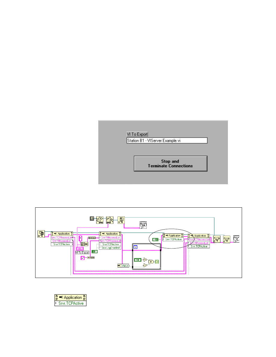
Module 2 Lesson 2 Exercises
LabVIEW Advanced I Course Manual
2-2-10
©
National Instruments Corporation
Exercise 2-4
Objective:
To study the communication of client and server VIs using the LabVIEW VI server.
You will finish building two VIs, one a server VI and the other a client VI.
The server VI will allow all remote clients to call a VI that it exports. The
client VI will run the exported VI and get data from this VI and display it.
1. Find a partner who has a computer connected to yours through TCP/IP
and decide which one of you is the client and which is the server. Open
the Server VIServer VI from
comclass.llb
. You will then finish
building the following VI.
Server Front Panel
Server Block Diagram
2. Finish the block diagram marked by the ellipse as shown above.
Property Node function (Application Control » Application Control
palette). Wire the Application Reference to the Reference input of the
Property Node function. Pop up and select Properties » Server » TCP
Listener Active. This property appears in the property node as
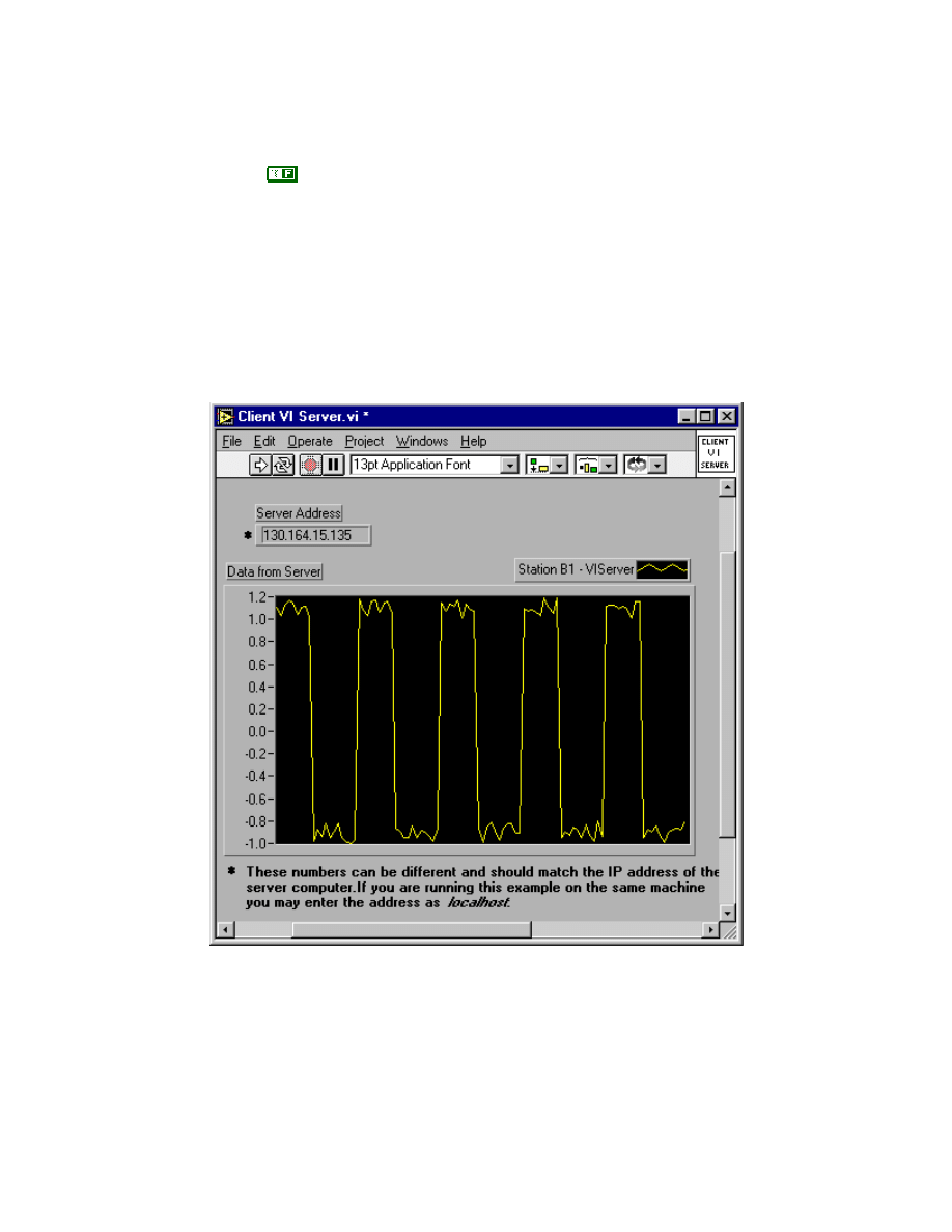
Module 2 Lesson 2 Exercises
©
National Instruments Corporation
2-2-11
LabVIEW Advanced I Course Manual
Srvr.TCPActive as shown. Pop up on the node and choose Change to
Write.
Boolean constant (Boolean palette) Select the Boolean constant. Wire it
to the Srvr.TCPActive property.
Finish wiring the Application references and the error cluster from the
While Loop to the property node specified by the Srvr.TCPActive
property. Save the VI.
3. Open the Client VI Server VI from
comclass.llb
. The front panel
and block diagram are shown below.
Client Front Panel
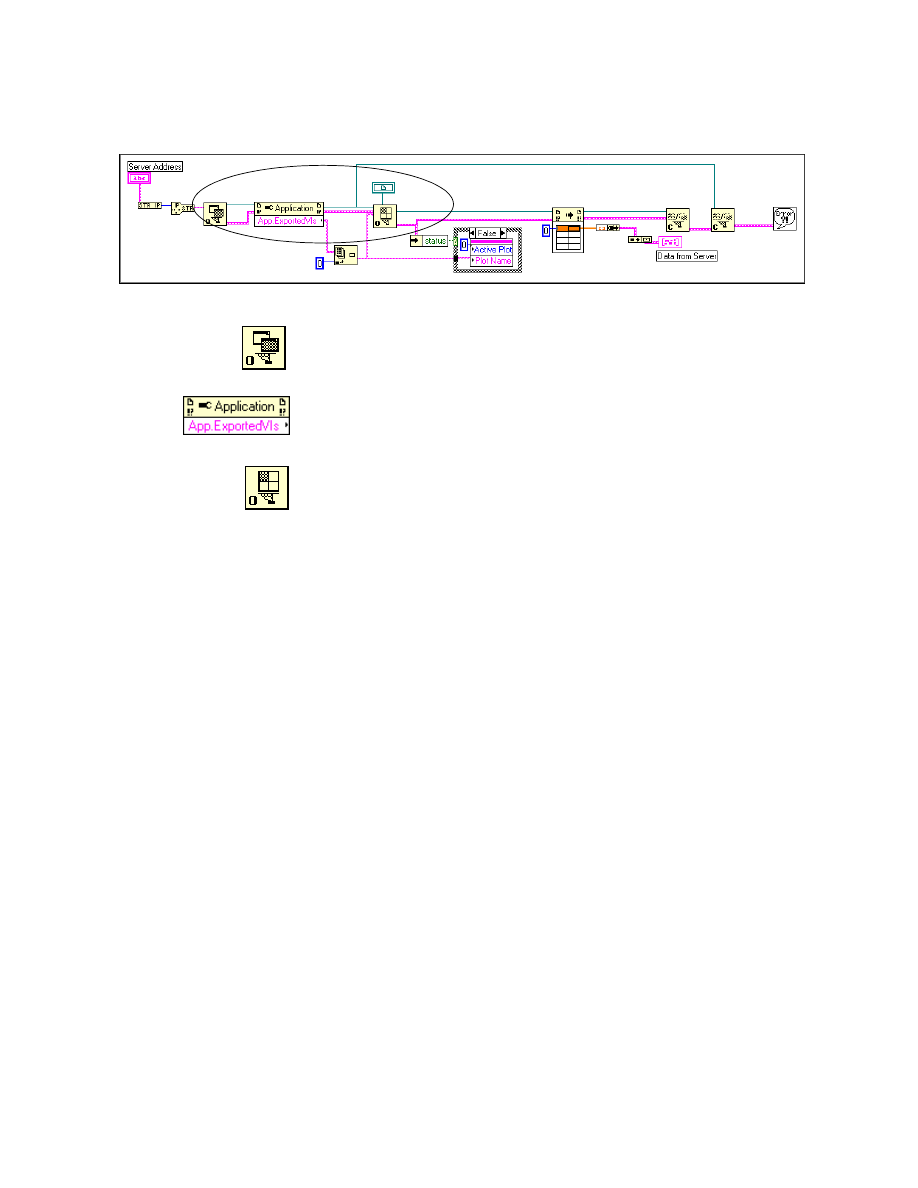
Module 2 Lesson 2 Exercises
LabVIEW Advanced I Course Manual
2-2-12
©
National Instruments Corporation
Client Block Diagram
4. Complete the block diagram within the ellipse as shown above.
Open Application Reference function (Application Control »
Application Control palette). Wire the output of the IP to String
function to the machine name input of this function.
Property Node function (Application Control » Application Control
palette). Pop up and select the property Exported VIs in Memory from
Application.
Open VI Reference function (Application Control » Application
Control palette). Wire the Strictly Typed VI Refnum to the type
specifier input of this function.
Finish the wiring and save the VI.
5. This is a simple example of a server that exports a VI to be called from
another machine. The VI listed in the VI to Export control is exported
by the server.
6. Two VIs are present in
comclass.llb
that can be exported by the VI
server on the server machine. Type in either
Station A1 - VIServer
Example.vi
or
Station B1 - VIServer Example.vi
in the VI
to Export control.
7. Run the
Server VIServer
VI. Specify the address of the server
machine on the front panel of the client VI in the Server Address front
panel control. If you are running the server and the client on the same
machine, you can keep this control blank or type
localhost
. Now run
the Client VI Server VI. You will see the data appear in the graph. This
data is obtained by running the exported VI, which can be Station A1 -
VIServer Example.vi or Station B1 - VIServer Example.vi. Click the
Stop button on the server VI to quit. This will turn off the server,
terminating all client connections, and restore the previous server
settings to their original values.
8. Try changing the name of the VI to export on the server VI and run the
server and client again.
9. The Server VIServer VI first saves all the present access settings of the
server such as TCPAccessList, VIAccessList, etc. It allows all clients to
access the server by setting the TCPAccessList to +*. It also exports the
specified VI by setting its value in the VIAccessList. A reference is

Module 2 Lesson 2 Exercises
©
National Instruments Corporation
2-2-13
LabVIEW Advanced I Course Manual
opened to the exported VI, and then the server waits in a loop until error
occurs or the user presses the STOP button. When you run the client VI,
it opens a reference to the server whose address is specified on its front
panel. Then it finds the exported VI and opens a strictly typed reference
to it. The Call By Reference Node runs the VI and gets the result, which
is then plotted on a graph on its front panel. The client then closes all
references and stops running. When user presses the stop button, it
restores all server settings and closes all references.
10. After you have finished running the VIs, close them.
End of Exercise 2-4

Module 2 Lesson 2 Exercises
LabVIEW Advanced I Course Manual
2-2-14
©
National Instruments Corporation
Notes
©
National Instruments Corporation
2-3-1
LabVIEW Advanced I Course Manual
Module 2
Lesson 3
Exercises
Exercise 3-1
Objective:
To observe and run a Visual Basic script using ActiveX Automation calls to access
LabVIEW.
You will examine how a macro written in Visual Basic script can control
LabVIEW’s ActiveX Automation server.
1. Launch Microsoft Excel on your machine.
2. Open the
freqresp.xls
file from
labview\examples\comm
directory. Microsoft Excel will prompt you with a dialog box and ask if
you would like to enable, disable, or not open the macro. Choose the
Enable macros option. The Workbook is shown below:
Frequency Response Demo
Amplitude
1
Number of Steps
100
Low Frequency
1
High Frequency
1000
Response Graph
-60
-50
-40
-30
-20
-10
0
1
10
100
1000

Module 2 Lesson 3 Exercises
LabVIEW Advanced I Course Manual
2-3-2
©
National Instruments Corporation
3. Select Tools » Macro » Macros… from the menu. Then choose the
LoadData() macro and then click on Edit.
Note
Do not double-click on LoadData().
4. The Microsoft Visual Basic editor will open and you can view the
LoadData() macro as shown below:
LoadData macro
Sub LoadData()
' LoadData Macro
' Keyboard Shortcut: Ctrl+l
' This is an example to demonstrate LabVIEW's Active-X server capabilities.
' Executing this macro loads a LabVIEW supplied example VI
"FrequencyResponse.vi",
' runs it and plots the result on an Excel Chart.
Dim lvapp As LabVIEW.Application
Dim vi As LabVIEW.VirtualInstrument
Dim paramNames(4), paramVals(4)
Set lvapp = CreateObject("LabVIEW.Application")
viPath = lvapp.ApplicationDirectory + "\examples\apps\freqresp.llb\Frequency
Response.vi"
Set vi = lvapp.GetVIReference(viPath) 'Load the vi into memory
vi.FPWinOpen = True 'Open front panel
' The Frequency Response vi has
' 4 inputs - Amplitude, Number of Steps, Low Frequency & High Frequency and
' 1 output - Response Graph.
' To run the Frequency Response VI, we invoke the Run method with names of inputs
' and outputs passed along with their values.
paramNames(0) = "Amplitude"
paramNames(1) = "Number of Steps"
paramNames(2) = "Low Frequency"
paramNames(3) = "High Frequency"
paramNames(4) = "Response Graph"
'initialize input values to the vi
paramVals(0) = Sheet1.Cells(4, 5) 'Amplitude value obtained from cell (4,5)
paramVals(1) = Sheet1.Cells(5, 5) '# steps value obtained from cell (5,5)
paramVals(2) = Sheet1.Cells(6, 5) 'Low Frequency value obtained from cell (6,
5)
paramVals(3) = Sheet1.Cells(7, 5) 'High Frequency value obtained from cell (7,
5)
' paramVals(4) will contain the value of Response Graph after
' running the vi.

Module 2 Lesson 3 Exercises
©
National Instruments Corporation
2-3-3
LabVIEW Advanced I Course Manual
'run the vi
Call vi.Call(paramNames, paramVals)
'paramVal(4) contains value for Response Graph - a cluster of 2 arrays
'In Active-X we view a cluster as an array of variants
'so, a cluster of 2 elements x & y is an array of 2 variant elements
x = paramVals(4)(0) ' x co-ordinates
y = paramVals(4)(1) ' y co-ordinates
'Fill the excel columns 1 & 2 with the graph co-ordinates
'These columns are used by Excel to plot the chart
first = LBound(x, 1)
last = UBound(x, 1)
Sheet1.Columns(1).Clear
Sheet1.Columns(2).Clear
For i = first To last
Sheet1.Cells(i - first + 1, 1) = x(i)
Sheet1.Cells(i - first + 1, 2) = y(i)
Next I
End Sub
5. Study the LoadData macro by examining the script. The macro opens
up the Frequency Response VI from
examples\apps\
freqresp.llb
. It then sets the values of the various front panel
controls. Finally, it runs the VI and returns the array data and plots the
Response graph in Excel. Notice the following in the source code:
a. The script creates a creatable class LabVIEW.Application using the
CreateObject function. Then it places the Frequency Response VI
in memory and returns the pointer of the VI by using the
GetVIReference function.
b. The Call method is used to call the VI. The front panel controls
(inputs) and indicators (outputs) are passed as parameters to the Call
function.
c. ParamNames is an array of strings that contains the names of the
front panel objects of this VI. This VI has four inputs and one output,
which is the Response graph. ParamVals is an array that contains the
input values for the input parameters and the return values from the
output parameters in the order in which names were specified in
paramNames.
d. The fourth paramVal contains value for the Response graph which is
a cluster of two arrays. In ActiveX, a cluster is an array of variants.
Hence, a cluster of two elements x and y is an array of two variant
elements.
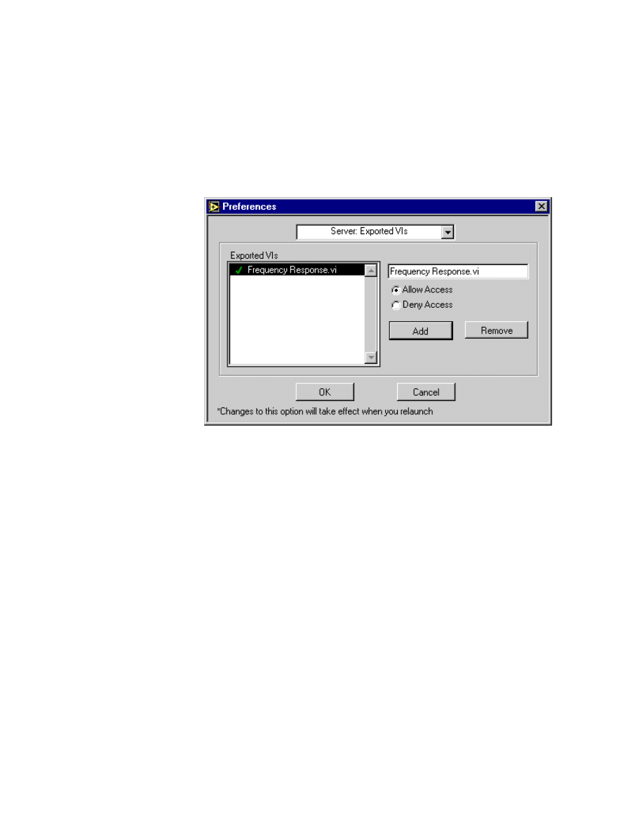
Module 2 Lesson 3 Exercises
LabVIEW Advanced I Course Manual
2-3-4
©
National Instruments Corporation
e. The values of x coordinates and y coordinates are filled in columns
1 and 2 in Excel. Excel uses these columns to plot the chart.
6. In LabVIEW, select Edit » Preferences » Server Configuration and
enable the ActiveX Protocol. Under Edit » Preferences »
Server:Exported VIs, enable access to the Frequency Response VI.
Also, make sure that LabVIEW is set up to login automatically. Next,
quit LabVIEW.
7. After you have finished examining the source code, close the Visual
Basic editor by choosing Close and Return to Microsoft Excel from
the File menu. Run the macro in XL by pressing <Ctrl-L>. You can also
run the macro through the Microsoft Visual Basic editor by selecting
Run » Run Sub/User Form. You can clear the chart by pressing
<Ctrl-M>.
8. After you are done running the macro, close Excel and the Frequency
Response VI. Do not save any changes.
9. As a further exercise, modify the LoadData() macro in
freqresp.xls
to close the Frequency Response VI automatically.
End of Exercise 3-1
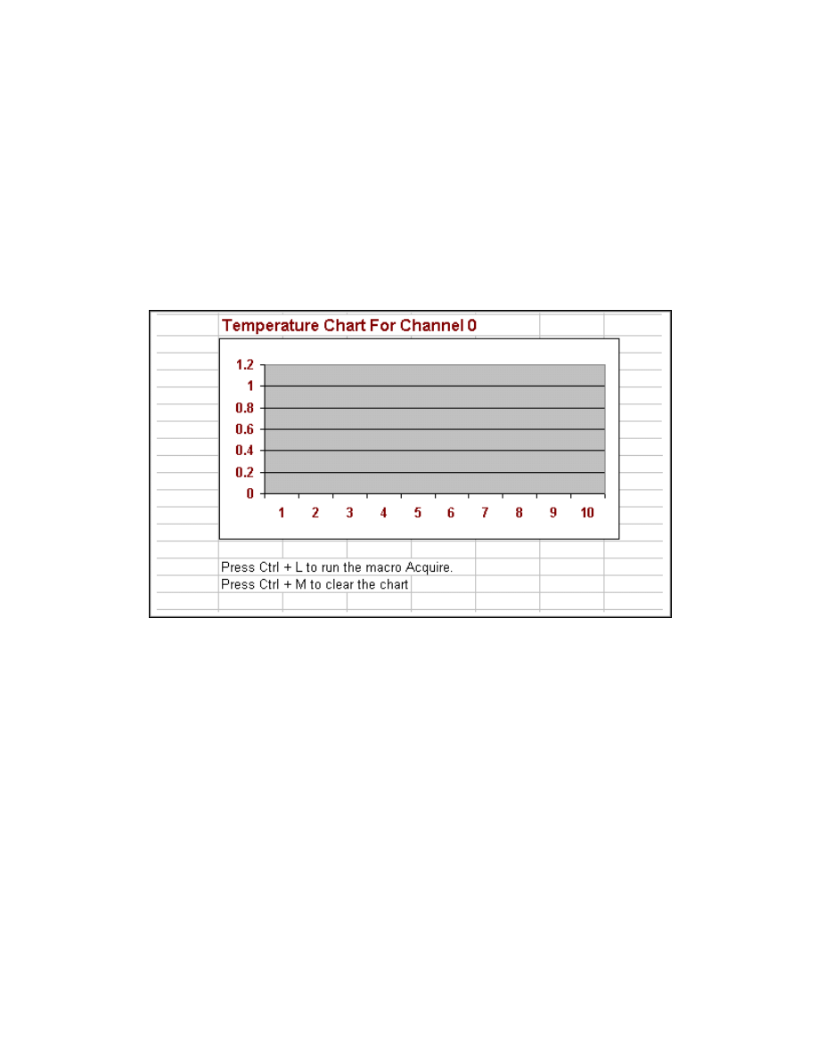
Module 2 Lesson 3 Exercises
©
National Instruments Corporation
2-3-5
LabVIEW Advanced I Course Manual
Exercise 3-2
Objective:
To write and run a Visual Basic script using ActiveX Automation calls to access a
LabVIEW VI.
You will write a macro in Visual Basic script to control LabVIEW’s
ActiveX Automation server. You will open and run a LabVIEW VI.
1. Launch Excel on your machine.
2. Open the
acquire.xls
file from the
LV_AdvI
directory. Choose
Enable macros from the dialog box that Excel displays. The Workbook
is shown below:
3. Open the Visual Basic Editor by choosing Tools » Macro » Visual
Basic Editor. Part of the source code is already written for you. You will
complete the Acquire_Data() macro by typing in the source code
marked in bold. A keyboard shortcut of <Ctrl-L> is already assigned to
the macro.
Sub Acquire_Data()
' Run the Acquire 1 Point from 1 Channel VI in LabVIEW.
' This macro will change the Front Panel title of the VI
' It will also save the VI in HTML format.
' 10 Points will be acquired from the Temerature sensor on your
' DAQ Signal Accessory.
Dim lvapp As LabVIEW.Application
Dim vi As LabVIEW.VirtualInstrument
Dim ParamVals(4)
Set lvapp = CreateObject("LabVIEW.Application")
viPath = lvapp.ApplicationDirectory +
"\examples\daq\anlogin\anlogin.llb\Acquire 1 Point from 1 Channel.vi"

Module 2 Lesson 3 Exercises
LabVIEW Advanced I Course Manual
2-3-6
©
National Instruments Corporation
Set vi = lvapp.GetVIReference(viPath) 'Load the vi into memory
vi.FPWinOpen = True 'Open front panel
vi.FPWinTitle = "Acquire A Point"
Call vi.PrintVIToHTML ("c:\exercises\LV_AdvI\Acquire.htm",0,4,eJPEG,
256, "C:\exercises\LV_AdvI")
Call vi.SetControlValue("device", "1")
Call vi.SetControlValue("channel", "0")
For i = 1 To 10
Call vi.Run
Sheet1.Cells(i) = vi.GetControlValue("sample")
Next i
End Sub
4. Save the changes to
acquire.xls
. A Clear_Chart macro is already
recorded for you with a keyboard shortcut of <Ctrl-M>. The code for
this macro is shown below.
Sub Clear_Chart()
'
' Clear_Chart Macro
' Keyboard Shortcut: Ctrl+M
'
Sheet1.Rows(1).Clear
End Sub
5. Make sure that you have enabled the ActiveX server access through
LabVIEW. You can accomplish this by selecting Edit » Preferences »
Server Configuration and enabling the ActiveX Protocol. Under
Edit » Preferences » Server:Exported VIs, enable access to Acquire
1 Point from 1 channel VI.
6. Run the macro by pressing <Ctrl-L>. Notice the following about the
macro source code.
a. The macro first creates a class for the application LabVIEW and
creates a reference to the Acquire 1 Point from 1 Channel VI.
b. The macro uses the functions SetControlValue and
GetControlValue to set or get values of the front panel controls and
indicators.
c. This macro changes the title of the front panel to Acquire a Point. It
also saves VI information to the HTML file
Acquire.htm
, which
is saved in your
C:\exercises\LV_AdvI
directory.
d. This macro runs the Acquire 1 Point from 1 Channel VI using the
Run method in a For Loop to get 10 readings from the temperature
sensor on your DAQ Signal Accessory. Then Excel plots the
Temperature Chart.
e. The Get/SetControlValue functions use the control/indicator labels
to identify a control or indicator.

Module 2 Lesson 3 Exercises
©
National Instruments Corporation
2-3-7
LabVIEW Advanced I Course Manual
7. You can clear the chart by pressing <Ctrl-M>.
8. Launch Internet Explorer and open the
Acquire.htm
file from your
exercises\LV_AdvI
directory. This page describes all the
information about the VI.
9. After you are finished running the macro, close Excel and the Acquire
1 Point from 1 Channel VI in LabVIEW.
End of Exercise 3-2

Module 2 Lesson 3 Exercises
LabVIEW Advanced I Course Manual
2-3-8
©
National Instruments Corporation
Exercise 3-3
Note
If you have access to a compiler, build the executable Acquire.exe.
Objective:
To examine C++ source code and run its executable, which uses ActiveX Automation
client calls to access LabVIEW’s Automation server.
You will examine and run a Visual C++ executable to control LabVIEW’s
ActiveX Automation server. This program accomplishes the same task that
the Acquire macro did in Exercise 3-2. It loads and runs the Acquire 1
Point from 1 Channel VI.
1. Open the C source file
Acquire.cpp
from the
c:\exercises\LV_AdvI
directory in an editor of your choice.
2. The source code is as shown below. This C code demonstrates the
technique required to create a simple automation client to control
LabVIEW.
//Acquire.cpp : This source code is an Automation client. It calls the
// LabVIEW 5.0's automation server. It loads the VI Acquire 1 Point from 1
//Channel VI and runs it.
//
#include "windows.h"
#include "stdio.h"
#include "conio.h"
#include <stdlib.h>
#include <string.h>
#include <iostream.h>
#import "c:\program files\National Instruments\LabVIEW\RESOURCE\labview50.tlb"
main()
{
VARIANT sample;
int size = 0;
Char Path [1000];
// define the path to the application
char VIPath[100] = "\\examples\\daq\\anlogin\\anlogin.llb\\
Acquire 1 Point from 1 Channel.vi";
// Generate a namespace declaration to and identify and assign a name to a
//declarative region.
// In this case we are assigning LabVIEW.
using namespace LabVIEW;
_ApplicationPtr pLV;
VirtualInstrumentPtr pVI;
CoInitialize(NULL);
do
{

Module 2 Lesson 3 Exercises
©
National Instruments Corporation
2-3-9
LabVIEW Advanced I Course Manual
pLV.CreateInstance("LabVIEW.Application");
if (pLV == NULL)
{
printf("LV must be running, exiting ...\n");
break;
}
pVI.CreateInstance("LabVIEW.VirtualInstrument");
strcpy(Path, pLV->ApplicationDirectory);
strcat(Path, VIPath);
// assign an object reference to the pVI.
pVI = pLV->GetVIReference(LPCTSTR(Path));
// configure the VI to close its front panel after the call statement
pVI->ShowFPOnCall = TRUE;
pVI->SetControlValue("device","1");
pVI->SetControlValue("channel", "0");
//Transfer control to LabVIEW with the Run statement. The call function
//passes the parameter names
// and data to the LabVIEW VI.
pVI->Run();
sample = pVI->GetControlValue("sample");
printf("The sample Value is %f \n", sample.fltVal);
while( !kbhit() )
cout << "Hit any key to continue\r";
fflush (stdin);
pLV->AutomaticClose=0;
} while (0);
CoUninitialize();
return (0);
}
3. Notice the following about the source code.
a. The front panel indicator sample is declared as a Variant. A Variant
data type is a self-describing data type and this type is used to
declare front panel objects in ActiveX.
b. A namespace is a declarative region that places any definitions
declared within it into an unique scope. The namespace identifier in
this case is LabVIEW. All declarations with namespace LabVIEW
are defined in
labview50.tlb
. _ApplicationPtr and
VirtualInstrumentPtr are declared within the LabVIEW namespace
in
labview50.tlb
, LabVIEW’s type library.
c. Notice the use of the CoIntialize() function. All applications must
call this function before calling any COM library function. This
function initializes the COM library.

Module 2 Lesson 3 Exercises
LabVIEW Advanced I Course Manual
2-3-10
©
National Instruments Corporation
d. Notice the use of the CoUninitialize() function. All applications that
use COM functions should call this function at the end of their
source code. This function call closes the Component Object Model
library and frees up any resources that have been used and closes all
connections.
e. Notice the use of the SetControlValue and GetControlValue methods
to set and get the values of the front panel controls.
f.
The Run method is used to run the Acquire 1 Point from 1
Channel VI.
4. This source code has been compiled into a Win32 console application
using the Microsoft Visual C++ 5.0 compiler.
5. Before you run this application, make sure that LabVIEW on your
machine is configured to enable ActiveX access. Also, make sure that
the Acquire 1 Point from 1 Channel VI is allowed access.
6. Run the
Acquire.exe
application from the
c:\exercises\LV Adv
I
directory. This application will launch LabVIEW through automation
and will load the Acquire 1 Point from 1 Channel VI from the
examples directory. Then it runs the VI and returns the value of the
sample acquired from the temperature sensor on your demo box at the
DOS prompt. You will be prompted to press any key to exit the
application.
7. After you are finished, close LabVIEW.
End of Exercise 3-3
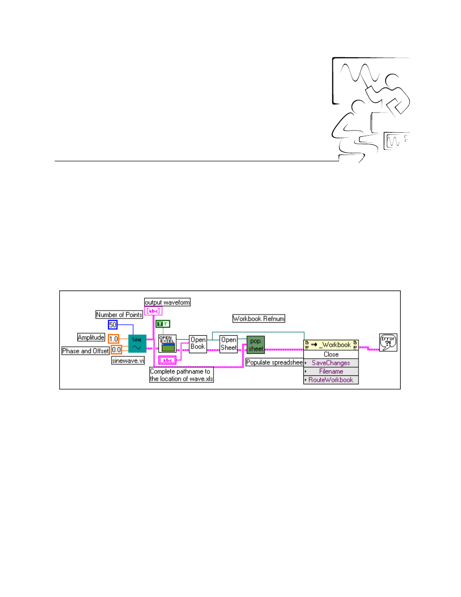
©
National Instruments Corporation
2-4-1
LabVIEW Advanced I Course Manual
Module 2
Lesson 4
Exercises
Exercise 4-1
Objective:
To examine and run a VI using ActiveX Automation calls to access Microsoft Excel
to input values.
You will examine how a LabVIEW client VI inputs an array of data into
Excel and then plots a chart via ActiveX Automation calls.
Block Diagram
1. Open the Generate Sine Wave in XL VI from
comclass.llb
. The VI
is already built for you.
2. On the front panel of the VI, specify the full pathname to the location of
the Excel Workbook
wave.xls
.
wave.xls
is in your
exercises\LV_AdvI
directory.
3. Run Generate Sine Wave in XL VI.
4. This VI inputs 50 sine wave points to Sheet 1 of the Workbook
wave.xls
from Row 3 to Row 52 in Column 1. Because this range is
associated with the Sine Wave Chart on sheet1, Excel plots the chart.
5. Examine the block diagram of this VI. Note that the sinewave VI
generates an array of 50 sine wave points. LabVIEW uses the concept
of refnums to access the different methods and properties of Excel.
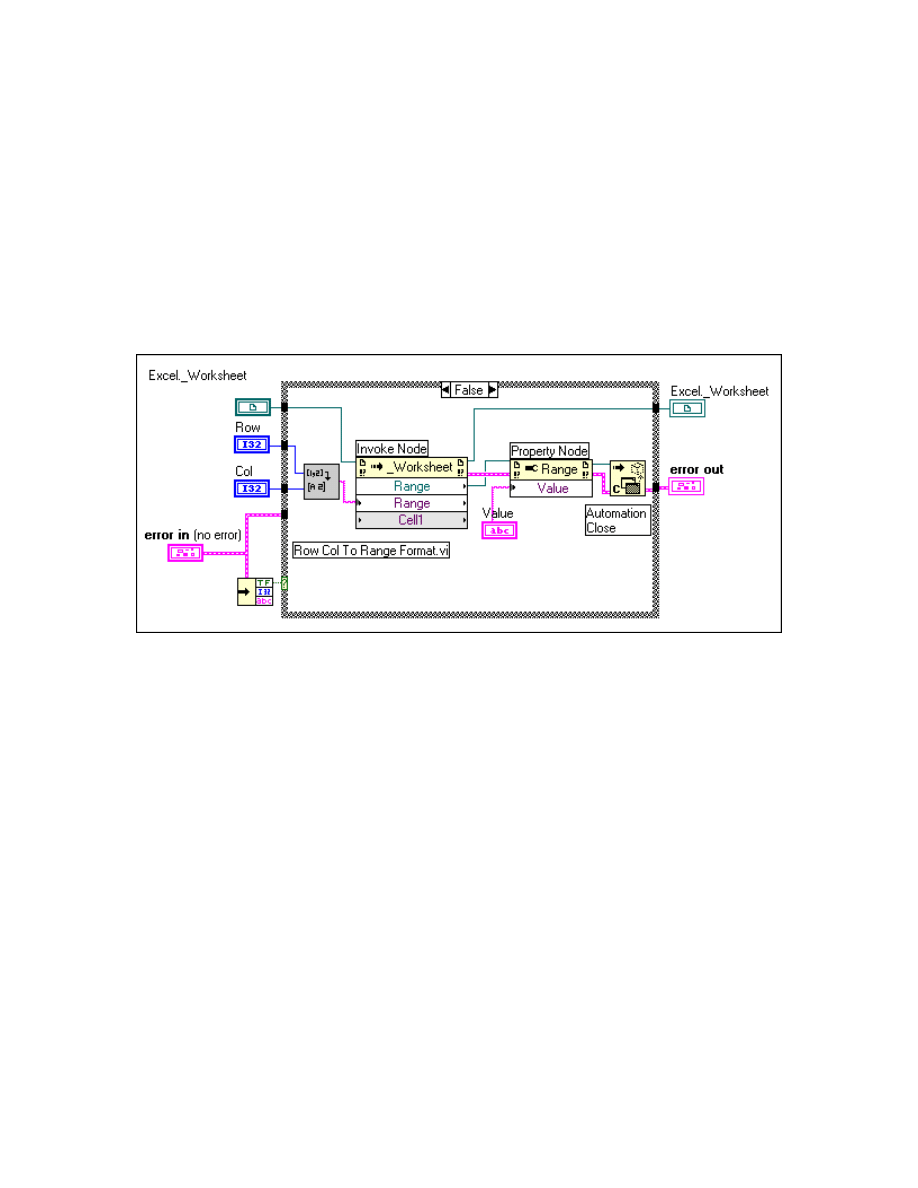
Module 2 Lesson 4 Exercises
LabVIEW Advanced I Course Manual
2-4-2
©
National Instruments Corporation
6. For LabVIEW to fill data in Excel, it must traverse the object hierarchy.
Hence, the VI first accesses the Application object, Workbook object,
Worksheet object, and then the Range object.
7. In the Open Workbook By Name VI, LabVIEW accesses the
Workbook
wave.xls
by accessing the Application object. Next, in the
Open Worksheet VI, LabVIEW accesses the Worksheet object.
8. The Populate Spreadsheet Values VI and the Set Cell Value subVI
use the Range method to access a specific cell and the Value property to
set the value of that cell. The block diagram of the Set Value VI is
shown below.
9. Finally, the Close method closes the Workbook object.
10. After you are finished, close the VI. Do not save any changes. Also,
close
wave.xls
and do not save any changes. Close Excel.
End of Exercise 4-1
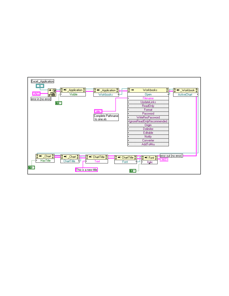
Module 2 Lesson 4 Exercises
©
National Instruments Corporation
2-4-3
LabVIEW Advanced I Course Manual
Exercise 4-2
Objective:
To examine and run a VI that changes the text and font style of an existing chart in
Microsoft Excel using ActiveX Automation calls from a LabVIEW VI.
You will examine how a LabVIEW client VI changes the text and font style
of an existing chart in Excel via ActiveX Automation.
Block Diagram
1. Open the Title VI from
comclass.llb
. The VI is already built for you.
2. On the front panel of the VI, specify the full pathname to the location of
the Excel Workbook
sine.xls
.
sine.xls
is in your
exercises\LV_AdvI
directory.
3. Run the Title VI. LabVIEW opens the Workbook
sine.xls
, which has
an existing title, Sine. This title is changed to “This is a new title” and
the font is set to Italic. When you close Excel, do not save any changes
to
sine.xls
.
4. Examine the block diagram of the Title VI. Part of the block diagram is
shown above.
5. Recall that to access a method or property of an object in Excel, you
must traverse the object hierarchy; the VI first accesses the Application
object, then the Workbook object, and then the Charts object.

Module 2 Lesson 4 Exercises
LabVIEW Advanced I Course Manual
2-4-4
©
National Instruments Corporation
6. The Chart Title is set to TRUE by accessing the HasTitle property. The
new title is set using the Text property of the ChartTitle object. Next, the
Italic property of the Font object is used to set the title to be italicized.
7. After you have finished, close the VI. Do not save any changes.
Note
To obtain help on any selected property or method, pop up on the function and
select Help for that particular property or method. You must install Microsoft
Visual Basic Reference Help for this to work.
End of Exercise 4-2
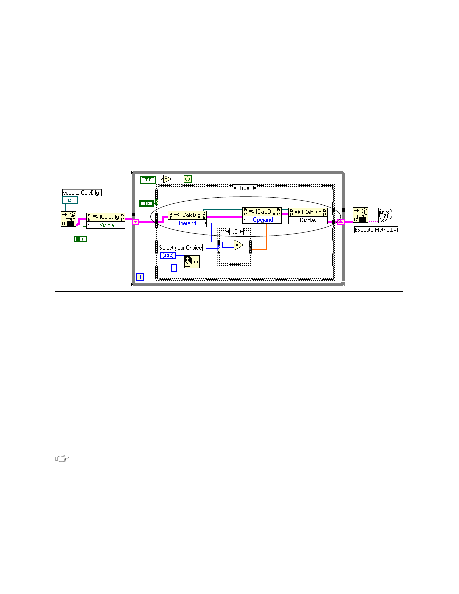
Module 2 Lesson 4 Exercises
©
National Instruments Corporation
2-4-5
LabVIEW Advanced I Course Manual
Exercise 4-3
Objective:
To complete and run an Automation Client VI that controls an ActiveX Automation
Server.
You will finish building the VI to access the calculator Automation server.
The Calculator server example also has a type library. You will refer to this
library for information on properties and methods.
Block Diagram
1. Open the calc VI from
comclass.llb
. You will finish building the
block diagram of this VI.
2. Make sure that you run the utility, “vccalc.reg.” This utility is in the
exercises\LV_AdvI
directory. It registers the vccalc.calculator
object in the registry. In this VI you will call the methods and properties
of the vccalc.calculator object exposed by the automation server
vccalc.exe
.
3. If you have the Visual C++ compiler loaded on your machine, use the
OLE/Com Object Viewer from the Tools menu to browse through
vccalc’s type library
vccalc.tlb
.
4. Examine the block diagram of the calc VI. Pop up on the vccalc.CalcDlg
automation refnum and select the calculator’s type library from
c:\exercises\LV_AdvI\vccalc.tlb
.
Note
If wires on the block diagram are broken when you open the VI, you should
reselect the properties by popping up on the node.
You will complete the part of the block diagram marked by the ellipse.
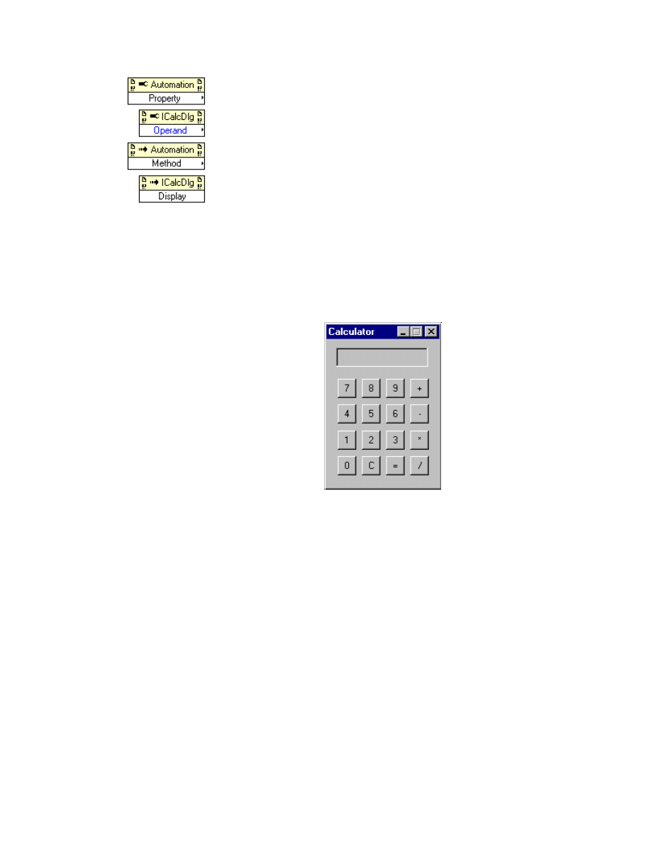
Module 2 Lesson 4 Exercises
LabVIEW Advanced I Course Manual
2-4-6
©
National Instruments Corporation
Property Node function (Communications » ActiveX palette). Once
you wire the Automation reference to this function, it automatically
displays the name of the automation object it is accessing, and then you
can choose the property to be Operand.
Invoke Node function (Communications » ActiveX palette). Once you
wire the automation reference to the Invoke Node Function, it displays
the automation object it is accessing. You will now be able to select from
a list of methods it exposes. Select the Display method.
5. After you have finished building the block diagram, save the changes
you have made.
6. Run the calc VI. The Automation Open function creates an object of
type vccalc.IcalcDlg (that is, a calculator object). The Visible property
is set to TRUE, and the calculator is displayed on the left side of your
screen as shown below.
7. Enter a number in the calculator, select either Square of Number or
Square Root option from the menu, and click on the Boolean “Press
Button after value entered in calculator and Selection has been made.”
The number you entered into the calculator window is fetched in the
LabVIEW diagram using the Operand property. The appropriate
calculation is done in the LabVIEW block diagram and the result is sent
to the calculator window via the Display method. Experiment with
different values.
8. After you have finished, close the VI.
End of Exercise 4-3
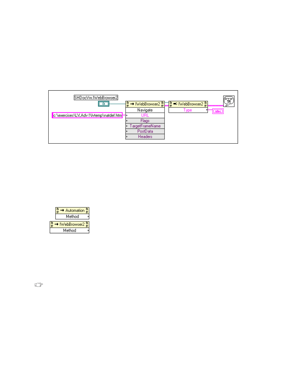
Module 2 Lesson 4 Exercises
©
National Instruments Corporation
2-4-7
LabVIEW Advanced I Course Manual
Exercise 4-4
Objective:
To control a Web Browser Object using an ActiveX Control in LabVIEW.
You will build a VI that controls a Web Browser Object using an ActiveX
control container in LabVIEW.
Block Diagram
1. Open a new VI in LabVIEW. From the Controls » ActiveX palette,
select the container object. Resize it to be very large on your front panel.
2. Pop up in the container and select Insert ActiveX object. From the
Select ActiveX Object dialog box, select Create Control. A list of all
available objects is displayed. Next, scroll through the list and select the
Microsoft Web Browser control.
3. Switch to the block diagram. You can now use automation functions
with this refnum. Complete it as shown above.
Invoke Node function (Communications » ActiveX palette). Once you
wire the automation reference of the control container to the Invoke
Node Function, it will display the automation object (IwebBrowser2) it
is accessing. You now can select from a list of methods it exposes. Select
the Navigate method.
4. Pop up on the URL input and select Create Constant. Type the
following:
c:\exercises\LV_AdvI\lvtemp\ natdef.htm
.
This is the path to the
default.htm
file on your machine.
5. Return to the front panel and run the VI. You will see the default home
page of National Instruments.
Note
If you are connected to the Internet, you can instead type www.natinst.com
and see a live Internet connection.

Module 2 Lesson 4 Exercises
LabVIEW Advanced I Course Manual
2-4-8
©
National Instruments Corporation
6. You can also use the Property Node to get and set properties of the
ActiveX Control. Wire the Property Node of the IWebBrowser object to
find its type. Run the VI. The control type is __________________.
7. After you finish, save the VI as Web Object.vi.
End of Exercise 4-4
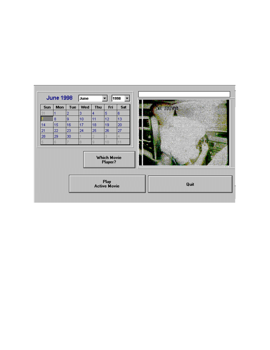
Module 2 Lesson 4 Exercises
©
National Instruments Corporation
2-4-9
LabVIEW Advanced I Course Manual
Exercise 4-5
Objective:
To control different ActiveX controls through the LabVIEW ActiveX Container control.
You will complete a VI that controls a Calendar control and an Active
Movie Control using an ActiveX control container in LabVIEW.
Front Panel
1. Open the Container Example VI from
comclass.llb
. The front
panel of the VI is already built for you as shown above. The front panel
of the VI contains two ActiveX control objects. The first object is the
Calendar object and the second object is the Active Movie Control
object.
2. Switch to the block diagram and complete it as shown on the next page.
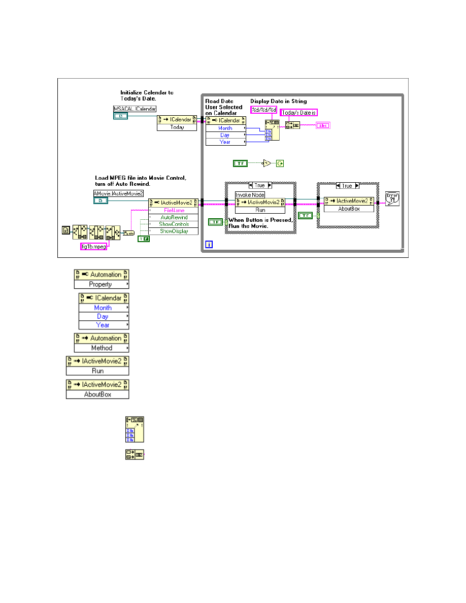
Module 2 Lesson 4 Exercises
LabVIEW Advanced I Course Manual
2-4-10
©
National Instruments Corporation
Block Diagram
3. Finish programming the block diagram using the following functions.
Property Node function (Communications » ActiveX palette). Once
you wire the Automation reference of the ICalendar object, you can
select the required properties of Month, Day and Year.
Invoke Node function (Communications » ActiveX palette). Once you
wire the automation reference of the IActiveMovie2 container to the
Invoke Node function, you can select the required methods (Run and
AboutBox methods).
Format Into String function (String palette). Resize the function so
that three terminals are seen. Wire Month, Day, and Year from the
ICalendar property node to this function.
Concatenate Strings function (String palette).
4. In this VI, you have programmed the Calendar object to display today’s
date by accessing the method Today. You have also read the existing
date from the Calendar control and displayed it in LabVIEW’s string
indicator.
5. You have also accessed the IActiveMovie2 control and disabled the
movie control and auto rewind features. You will load the MPEG file
fig1b.mpeg
into the control. You have used the Run method to run the

Module 2 Lesson 4 Exercises
©
National Instruments Corporation
2-4-11
LabVIEW Advanced I Course Manual
movie clip and the AboutBox method to access the information about
the server application to which this control belongs.
6. After you finish building the block diagram, save the VI. Return to the
front panel and run the VI. Today’s date will be displayed in the
Calendar control. To run the Active Movie, press on the Boolean button
marked Play Active Movie. The movie contained in
fig1b.mpeg
is
played on the movie control container.
7. Click on the Which Player? button to get the About box for the server
application. Press QUIT to stop the VI.
8. After you finish, close the VI.
End of Exercise 4-5

Module 2 Lesson 4 Exercises
LabVIEW Advanced I Course Manual
2-4-12
©
National Instruments Corporation
Notes
©
National Instruments Corporation
3-1-1
LabVIEW Advanced I Course Manual
Module 3
Lesson 1
Exercises
Exercise 1-1
Objective:
To observe when the CIN routines are called during an operation on a VI.
You will load and run a VI that contains a CIN. While running the VI, you
will perform various operations on the VI, such as aborting, saving, and so
on. The CIN will display a message in the debugging window with the name
of the routine called during a particular operation.
Front Panel and Block Diagram
1. Open and examine Sequence.vi, located in
c:\exercises\LV_AdvI\CINCLASS.LLB
. LabVIEW will open a
debugging window in the background. The CINProperties function is
executed first, followed by the CINLoad function, followed by the
CINInit function. Together, these routines perform any initialization
you need before the VI runs. You will know that these routines have
executed, as they appear in the debugging window.
The block diagram contains a CIN and an infinite While Loop. The CIN
output is wired to the While Loop for artificial data dependency, forcing
the CIN to execute before the While Loop.
2. Run the VI. The CINProperties and CINRun functions should display
in the debugging window.
3. Abort the VI. The CINAbort function will display.
4. Move the label on the front panel and save your changes. The CINSave
function should display.

Module 3 Lesson 1 Exercises
LabVIEW Advanced I Course Manual
3-1-2
©
National Instruments Corporation
5. Close the VI. The CINDispose function appears, followed by
CINUnload.
6. Open the Display Text File VI from
CINCLASS.LLB
. Run the VI.
Select the
Sequence.c
file from the
SOURCES
directory. Notice the use
of the DbgPrintf function.
The DbgPrintf function is used to display the function being called. The
function prototype is defined in
extcode.h
as:
int32 DbgPrintf(CStr cfmt,........);
DbgPrintf takes a variable number of arguments, where the first
argument is a C format string. The first time you call the DbgPrintf
function, LabVIEW opens a window to display the text you pass the
function. Subsequent calls to this function appends new data as new
lines in the window.
Note
You do not need to pass in the new line character to the function.
This window is extremely useful in debugging your CINs. If you call the
DbgPrintf function with NULL instead of a format string, LabVIEW
closes the debugging window. You cannot position or change the size of
the window. The format of DbgPrintf is similar to the SPrintf function,
which is described in LabVIEW’s online reference.
End of Exercise 1-1
©
National Instruments Corporation
3-2-1
LabVIEW Advanced I Course Manual
Module 3
Lesson 2
Exercises
Exercise 2-1
Objective:
To examine the syntax of some memory manager functions.
You will open a file containing CIN source code. The code allocates
memory for a handle, copies the handle to a new address, and then releases
the block of memory that both handles use.
Block Diagram
1. Open Display Text File.vi in the
cinclass.LLB
library. You can use
this VI to display the text of the source file of your CIN within
LabVIEW.
2. Run the VI and click on the Display button. Select the source file
LVMemEx.c
in the
LV_AdvI\CFILES
directory.
This file was created using the Create .c file option from the CIN pop-up
menu.
/*
* CIN source file
*/
#include "extcode.h"
CIN MgErr CINRun(int32 *size);
CIN MgErr CINRun(int32 *size) {
/* ENTER YOUR CODE HERE */
return noErr;
}

Module 3 Lesson 2 Exercises
LabVIEW Advanced I Course Manual
3-2-2
©
National Instruments Corporation
3. Click on the Display button again and select the file
LVMemEx.c
in the
LV_AdvI\SOURCES
directory. The boldfaced code shown below is the
code particular to this CIN. The other code is the core code that all CINs
require.
4. Notice the following in the source code.
a. The variables a and b were defined as handles, but contain valid
handles only after the DSNewHandle and DSHandToHand
functions. Thus, the handle a points to a known block of memory.
b. You can use the DSHandToHand function to copy an existing
handle into a new handle. The old handle remains allocated and must
be deallocated using the DSDisposeHandle function.
c. Memory that a and b use is freed only after DSDisposeHandle is
called.
/*
* LVMemEx.c -> Shows the syntax of some LabVIEW Memory
* Manager routines
* parameters: Output: size -> pointer to the handle size
*/
#include "extcode.h"
#define BYTE_SIZE 1024L
CIN MgErr CINRun(int32 *size);
CIN MgErr CINRun(int32 *size) {
UHandle a, b;
a = DSNewHandle(BYTE_SIZE) /* a points to a 1024 bytes block *
b = a;
/* b points to the block a */
DSHandToHand(&b);
/* b points to a copy of a */
*size = DSGetHandleSize(b); /* return the size of b */
DSDisposeHandle(a);
/* release the memory used by a */
DSDisposeHandle(b);
/* release the memory used by b */
return noErr;
}
5. Open LVMemEx.vi from
cinclass.llb
. Run the VI.
6. The size is displayed on the front panel.
7. After you are done, close the VI. Do not save any changes.
End of Exercise 2-1
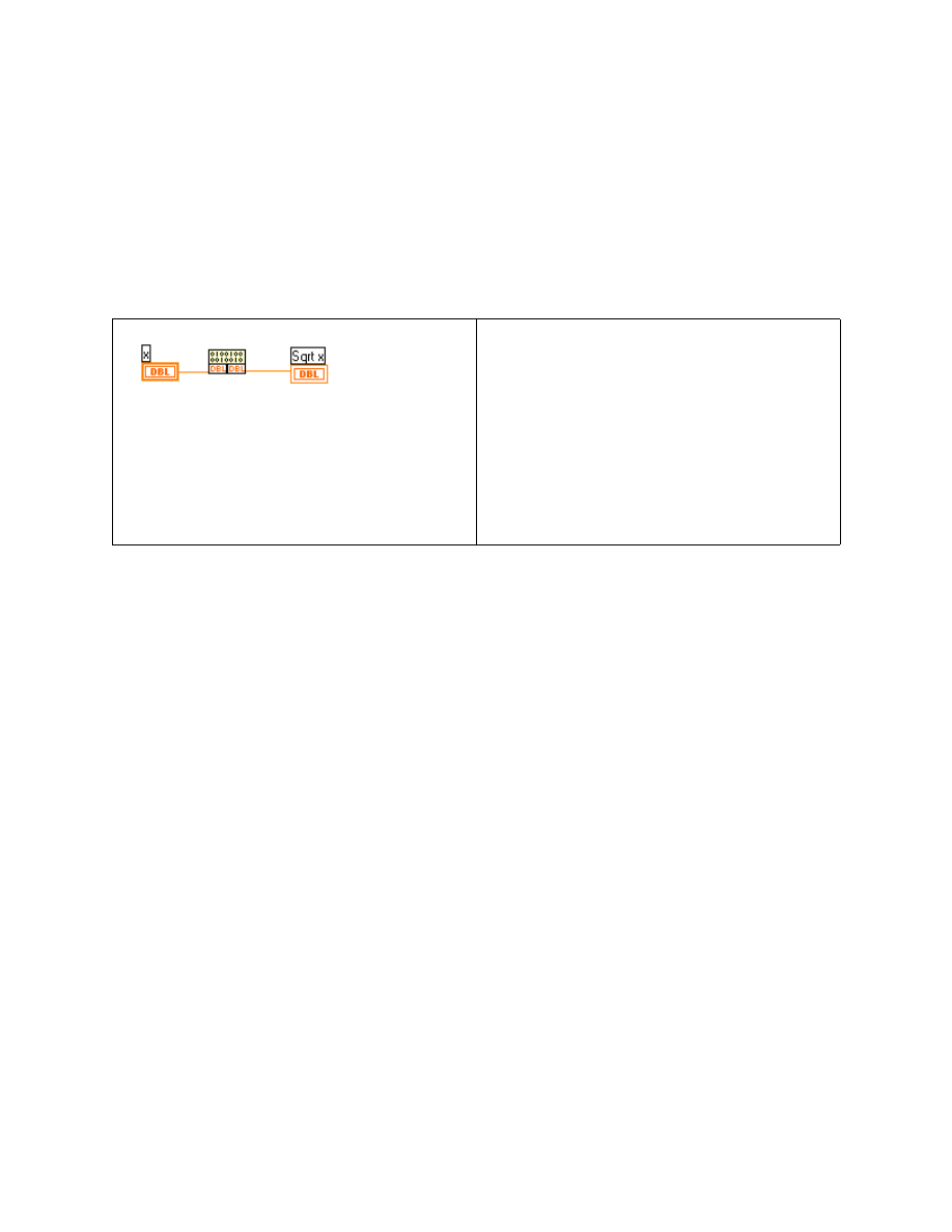
Module 3 Lesson 2 Exercises
©
National Instruments Corporation
3-2-3
LabVIEW Advanced I Course Manual
Exercise 2-2
Objective:
To examine the syntax of some support manager functions.
You will open a file that is the source code of a CIN. The code returns the
square root of a double-precision (DBL) number. If the number is negative,
-999.999 returns.
Block Diagram and Initial .C File
1. Click on the Display button in the Display Text File VI and select
LVSuppEx.c
in the
SOURCES
directory. The boldfaced code is specific
to this CIN. The remaining code is the core code required by all CINs.
2. Examine the source code below.
/*
* LVSuppEx.c -> Shows the syntax of some LabVIEW Support
* Manager routines
* parameters: I/O: number -> pointer to a float64 number
*/
#include "extcode.h"
CIN MgErr CINRun(float64 *number);
CIN MgErr CINRun(float64 *number) {
*number = (*number >= 0.0) ? sqrt (*number) : -999.999;
return noErr;
}
3. Open LVSuppEx.vi from
cinclass.llb
.
4. Enter a value for
x
. Run the VI. The CIN will return the square root of
x
.
5. Enter a negative number and run the VI. Make sure -999.999 returns.
6. After you are finished, close the VI. Do not save any changes.
End of Exercise 2-2
/*
* CIN source file
*/
#include "extcode.h"
CIN MgErr CINRun(float64 *x);
CIN MgErr CINRun(float64 *x) {
/* ENTER YOUR CODE HERE */
return noErr;
}
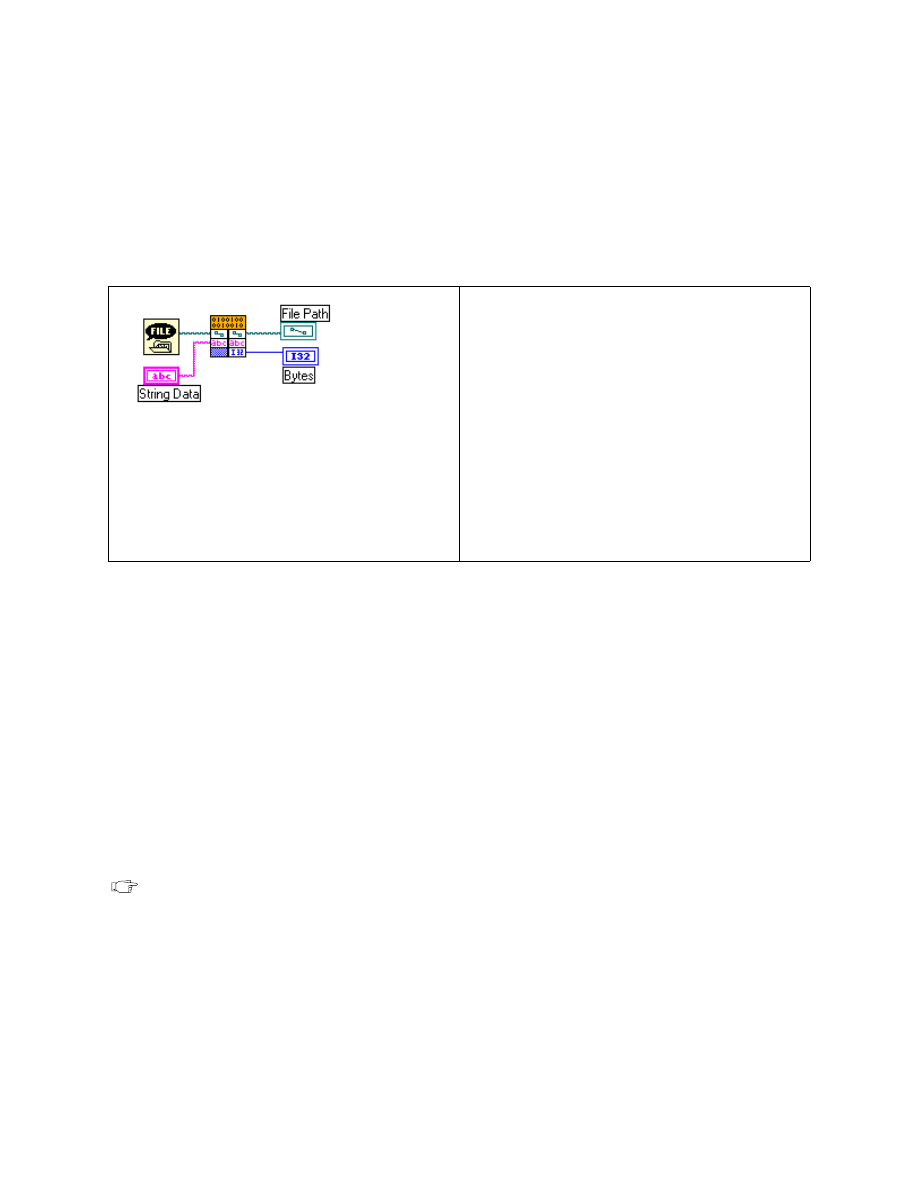
Module 3 Lesson 2 Exercises
LabVIEW Advanced I Course Manual
3-2-4
©
National Instruments Corporation
Exercise 2-3
Objective:
To examine the syntax of some file manager functions.
You will examine the code for a CIN that saves data to a new file. The file
path and the string to write are passed from the block diagram.
Block Diagram and Initial .C File
1. Click on the Display button in the Display Text File VI and select
LVFileEx.c
in the
LV_AdvI\SOURCES
directory. The boldfaced code
is specific to this CIN. The remaining code is the core code required by
all CINs.
2. Examine the source code and notice the following.
a. The Path variable does not require memory allocation because
LabVIEW creates it and passes it to the CIN.
b. All file functions reference the file through the same File variable,
which is the file descriptor.
c. The support manager supplies the functions to directly access the
number of bytes in a string (LStrLen function) and the address of
the beginning of the data buffer (LStrBuf function).
Note
Error checking is recommended in every program. For example, if there is not
enough disk space, the FMWrite function can fail.
/*
* LVFileEx.c -> Creates a file and writes a string data into it.
* parameters: Input: fileName-> path for the file name
* fileData-> handle to the string to write
*
* Output: bytesOut-> pointer to an int32 number
*/
/*
* CIN source file
*/
#include "extcode.h"
CIN MgErr CINRun(Path path, LStrHandle
String_Data, int32 *Bytes);
CIN MgErr CINRun(Path path, LStrHandle
String_Data, int32 *bytes) {
/* ENTER YOUR CODE HERE */
return noErr;
}

Module 3 Lesson 2 Exercises
©
National Instruments Corporation
3-2-5
LabVIEW Advanced I Course Manual
#include "extcode.h"
#define PERMIT 65535L
CIN MgErr CINRun(Path fileName, LStrHandle fileData, int32 *bytesOut);
CIN MgErr CINRun(Path fileName, LStrHandle fileData, int32 *bytesOut) {
File
fileNum;
PStr
ignoredGroup;
int32
bytesIn;
MgErr
fileError = noErr;
ignoredGroup = (PStr)"\000";/* ignored for Mac and PC */
bytesIn= LStrLen(*fileData);
if(fileError = FCreate(&fileNum, fileName, PERMIT,
openReadWrite, denyNeither, ignoredGroup))
goto out;
/* create the file */
FMWrite(fileNum, bytesIn, bytesOut,
LStrBuf(*fileData)); /* write the data */
FMClose(fileNum);
/* close the file */
out:
return fileError;
}
3. Open LVFileEx.vi from
cinclass.llb
. Fill in String Data on the
front panel.
4. Run the VI. You will be prompted for a filename.
5. After the VI completes, it displays the number of byes written.
6. Run the VI several times.
7. After you are finished, close the VI. Do not save any changes.
End of Exercise 2-3

Module 3 Lesson 2 Exercises
LabVIEW Advanced I Course Manual
3-2-6
©
National Instruments Corporation
Notes
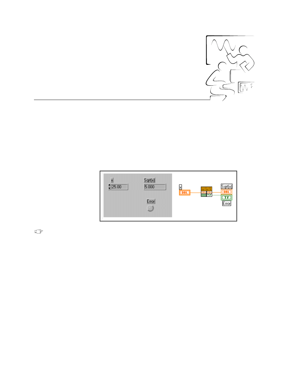
©
National Instruments Corporation
3-3-1
LabVIEW Advanced I Course Manual
Module 3
Lesson 3
Exercises
Exercise 3-1
Objective:
To pass numeric and Boolean arguments between a CIN and a code resource.
You will create a CIN that returns the square root of a DBL number. If the
number is negative, an error (Boolean) returns.
Front Panel and Block Diagram
Note
This exercise can be compiled only if you have Visual C++ or Symantec C on
WIN32. The compiled LSB is provided with Sqrt.vi in cinsoln.llb.
1. Build the VI front panel and block diagram as shown above. Be sure to
pop up on the Sqrt (x) indicator, choose Format & Precision, and set
the Digits of Precision to be 3.
2. Place a Code Interface Node (Advanced palette) on the block diagram.
3. Pop up on the first CIN parameter and choose Add Parameter. Change
the newly added parameter to an output by popping up on the second
parameter and choosing Output Only.
4. Wire the controls and indicators to the CIN.
5. Pop up on the CIN and select Create .c File from the pop-up menu. Type
Sqrt.c
in the dialog box and click OK. (Save your work in the
exercises\LV_AdvI\SQRT
directory). LabVIEW creates the
.c
file
shown on the next page.

Module 3 Lesson 3 Exercises
LabVIEW Advanced I Course Manual
3-3-2
©
National Instruments Corporation
/*
* CIN source file
*/
#include "extcode.h"
CIN MgErr CINRun(float64 *x, LVBoolean *Error);
CIN MgErr CINRun(float64 *x, LVBoolean *Error) {
/* ENTER YOUR CODE HERE */
return noErr;
}
Switch to an editor (Accessories » Wordpad) and open and examine
your source file. (You can also use the Display Text File VI in the
CINCLASS.LLB
library.)
Notice the following:
a. The CINRun routine deals with the input and output parameters.
b. The data types, float64 and LVBoolean, are not standard C data
types. They are LabVIEW data types.
6. Create the CIN source code. Add the boldfaced code to the file
Sqrt.c
and save the file.
/* Sqrt.c -> Returns the square root of a float64 number and an error
* parameters: Input/Output: x -> pointer to a float64 number
* Output : error-> pointer to a Boolean
*/
#include "extcode.h"
#include (math.h)
CIN MgErr CINRun(float64 *x, LVBoolean *Error);
CIN MgErr CINRun(float64 *x, LVBoolean *Error) {
if (*x >= 0.0) {
*x = sqrt(*x);
*Error= LVFALSE; /* no error */
}
else {
*x = -999.999;
*Error= LVTRUE;
/* error occurs */
}
return noErr;
}
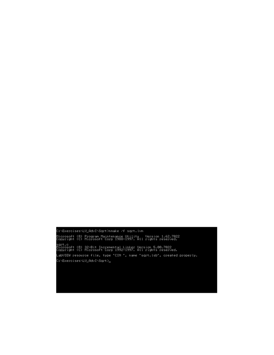
Module 3 Lesson 3 Exercises
©
National Instruments Corporation
3-3-3
LabVIEW Advanced I Course Manual
7. Notice the following in the source code:
a. The header file
extcode.h
associates LabVIEW types with C data
types and defines the LabVIEW routines that are accessible to
external code.
b. Only CINRun contains code. You rarely need to do anything with
the other routines.
c. The numeric and Boolean variables are passed as pointers.
d. A LabVIEW Boolean is a 8-bit unsigned integer that defines its
TRUE or FALSE state with a LVTRUE or LVFALSE value,
respectively.
e. The call to the sqrt function does not require a C library.
8. Save the CIN source code in the same
LV_AdvI\SQRT
directory.
9. Compile the CIN source code.
WIN32-Visual C++
10. Create a new makefile and save it as
Sqrt.lvm
. The makefile should
contain the following code:
name=Sqrt
type=CIN
!include $(CINTOOLSDIR)\ntlvsb.mak
11. Create the
Sqrt.lsb
CIN code by typing the following command in the
current prompt:
C:\exercises\LV_AdvI\SQRT>nmake /f Sqrt.lvm
The figure below describes the screen display during the compilation.
Notice that the display indicates that the
sqrt.lsb
file was created
properly.

Module 3 Lesson 3 Exercises
LabVIEW Advanced I Course Manual
3-3-4
©
National Instruments Corporation
WIN32-Visual C++ IDE
12. You can also use the Visual C++ IDE for CIN compilation. Follow the
steps shown below:
a. Create a new DLL project. Select File » New… and select
Win32
Dynamic-Link Library
as the project type. Name your project
sqrt
.
b. Add CIN objects and libraries to the project. Select Project » Add
To Project » Files… and select
cin.obj
,
labview.lib
,
lvsb.lib
, and
lvsbmain.def
from the
Cintools\Win32
subdirectory. These files are needed to build a CIN.
c. Add Cintools to the include path. Select Project » Settings… and
change Settings for: to
All Configurations
. Select the C/C++
tab and set the category to
Preprocessor
. Add the path to your
cintools directory in the Additional include directories: field.
d. Set alignment to
1 byte
. Select Project » Settings… and change
Settings For: to
All Configurations
. Select the C/C++ tab and
set the category to
Code Generation
. Choose
1 Byte
from the
Struct member alignment: tab.
e. Choose run-time library. Select Project » Settings… and change
Settings for: to
All Configurations
. Select the C/C++ tab and
set the category to
Code Generation
. Choose
Multithreaded
DLL
from the Use run-time library: tab.
f.
Make a custom build command to run
lvsbutil
. Select Project »
Settings… and change Settings for: to
All configurations
.
Select the Custom Build tab and change the Build commands field
to
"< your path to cintools>\win32\lvsbutil"
$(TargetName) -d $(WkspDir)\$(OutDir)
and the Output
file fields to
$(OutDir)$(TargetName).lsb
.
13. Add
sqrt.c
to your project. Then select Build sqrt.dll from the Build
menu.
Sqrt.lsb
will be created.
14. Switch to LabVIEW and load the code resource. Pop up on the CIN,
choose Load Code Resource, and select
Sqrt.lsb
.
15. Enter a number inside the numeric control and run the VI. The square
root of the number should return in the numeric indicator. Try a negative
number value. An error number value of -999.999 should return, and the
LED should be TRUE.
16. After you have finished, save your work and close all windows.
End of Exercise 3-1
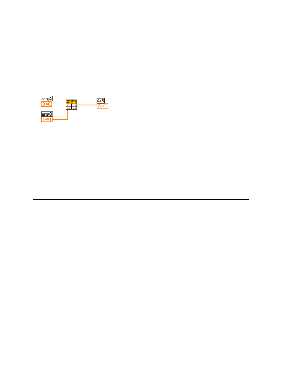
Module 3 Lesson 3 Exercises
©
National Instruments Corporation
3-3-5
LabVIEW Advanced I Course Manual
Exercise 3-2
Objective:
To observe how LabVIEW passes a 1D numeric array to a code resource.
You will examine a code resource that adds two 32-bit single-precision
(SGL) arrays. The result is returned in place of the first array.
Block Diagram and Initial .C File
1. Use the Display Text File VI to open and display the file
AddArray.c
in the
LV_AdvI\SOURCES
directory.
2. Examine the source code. Notice that the program assumes that both
input arrays have the same size. LabVIEW passes the handles that point
to each array and the code resource manipulates the values, but not the
array size. Also, notice that the result is returned in place of the first
array.
/*
* AddArray.c -> Adds two input arrays of single precision numbers
* parameters: In/Out :arrayA-> handle to an array of float32
* arrayB-> handle to an array of float32
*/
#include "extcode.h"
/*
* typedefs
*/
typedef struct {
/*
* CIN source file
*/
#include "extcode.h"
/*
* typedefs
*/
typedef struct {
int32 dimSize;
float32 arg1[1];
} TD1;
typedef TD1 **TD1Hdl;
CIN MgErr CINRun(TD1Hdl arrayA, TD1Hdl arrayB);
CIN MgErr CINRun(TD1Hdl arrayA, TD1Hdl arrayB)
{
/* ENTER YOUR CODE HERE */
return noErr;
}

Module 3 Lesson 3 Exercises
LabVIEW Advanced I Course Manual
3-3-6
©
National Instruments Corporation
int32 dimSize;
float32 arg1[1];
} TD1;
typedef TD1 **TD1Hdl;
CIN MgErr CINRun(TD1Hdl arrayA, TD1Hdl arrayB);
CIN MgErr CINRun(TD1Hdl arrayA, TD1Hdl arrayB) {
int32 i, n;
n = (*arrayA)->dimSize; /* n = number of elements */
for(i=0; i<n; i++)
/* Add the array elements */
(*arrayA)->arg1[i] = (*arrayA)->arg1[i] + (*arrayB)->arg1[i];
return noErr;
}
3. Open Addarray.vi from
cinclass.llb
. The VI is already built
for you.
4. If you have access to a compiler, compile the source code using the
Visual C++ compiler. Load the code resource into the CIN by popping
up on the CIN and selecting
AddArray.lsb
.
5. Run the VI. After you have finished, save and close the VI in
cinclass.llb
.
End of Exercise 3-2
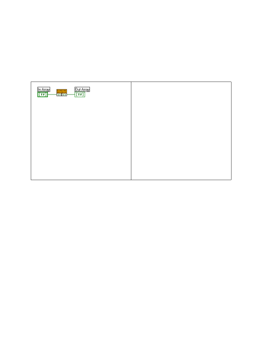
Module 3 Lesson 3 Exercises
©
National Instruments Corporation
3-3-7
LabVIEW Advanced I Course Manual
Exercise 3-3
Objective:
To examine code that shows how LabVIEW passes a Boolean array to a CIN.
You will examine a CIN that negates a Boolean array. The result is returned
in place of the input array.
Block Diagram and Initial .C File
1. Use the Display Text File VI to open and display the file
TFArray.c
in the
LV_AdvI\SOURCES
directory.
2. Notice the following in the source code:
a. LabVIEW passes the handle that points to the array, and the code
resource manipulates the values, but not the array size.
b. The number of elements in the array defines the number of elements
in the Boolean Array In_Array.
c. The result is returned in place of the input array.
/* TFArray.c -> Negates an input Boolean array
* parameters: In/Out: arrayIO -> handle to a Boolean array
*/
#include "extcode.h"
/*
* typedefs
*/
typedef struct {
/*
* CIN source file
*/
#include "extcode.h"
/*
* typedefs
*/
typedef struct {
int32 dimSize;
LVBoolean arg1[1];
} TD1;
typedef TD1 **TD1Hdl;
CIN MgErr CINRun(TD1Hdl In_Array);
CIN MgErr CINRun(TD1Hdl In_Array) {
/* ENTER YOUR CODE HERE */
return noErr;
}

Module 3 Lesson 3 Exercises
LabVIEW Advanced I Course Manual
3-3-8
©
National Instruments Corporation
int32 dimSize;
LVBoolean arg1[1];
} TD1;
typedef TD1 **TD1Hdl;
CIN MgErr CINRun(TD1Hdl In_Array);
CIN MgErr CINRun(TD1Hdl In_Array) {
int32 i, n;
n = (*In_Array)->dimSize; /* get the number of elements */
for(i=0; i<n; i++) /*negates every element in the array*/
(*In_Array)->arg1[i] = !(*In_Array)->arg1[i];
return noErr;
}
3. Open TFArray.vi from
cinclass.llb
. This VI is already built for
you.
4. If you have access to a compiler, compile the source code using the
Visual C++ compiler. Load the code resource into the CIN by popping
up on the CIN and selecting
TFArray.lsb
.
5. Run the VI. You will observe that
Out_Array
contains the negation of
In_Array
. After you have finished, save and close the VI in
cinclass.llb
.
End of Exercise 3-3
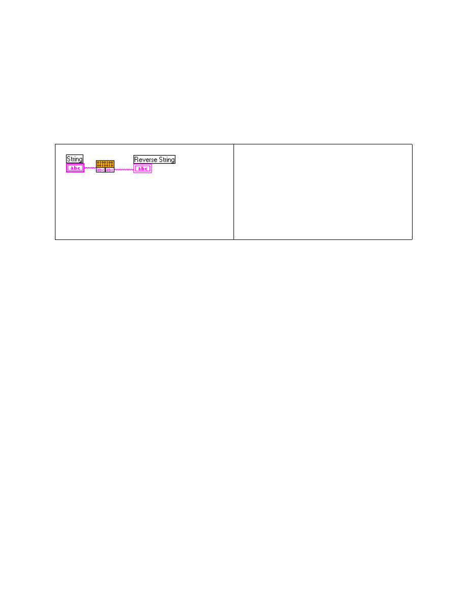
Module 3 Lesson 3 Exercises
©
National Instruments Corporation
3-3-9
LabVIEW Advanced I Course Manual
Exercise 3-4
Objective:
To examine code that shows how LabVIEW passes a string to a CIN.
(If you have access to a compiler, build the VI and code resource.)
You will examine a CIN that reverses the input string.
Block Diagram and Initial .C File
1. Use the Display Text File VI to open and display the file
Reverse.c
in the
LV_AdvI\SOURCES
directory.
2. Notice the following in the source code:
a. LabVIEW passes the handle that points to the string, and the code
resource manipulates the values, but not the array size.
b. The result is returned in place of the input string.
c. The code reverses the string in place.
/* Reverse.c = returns the reverse of the given input string
* parameters: string -> handle to a string
*/
#include "extcode.h"
CIN MgErr CINRun(LStrHandle String);
CIN MgErr CINRun(LStrHandle String) {
int32 i, j, size;
uChar cchar;
size = LStrLen (*String);
/*length of the string */
for(i=0, j = size - 1; i<j; i++, j--){
cchar = (*String)->str[i];
(*String)->str[i]= (*String)->str[j];
(*String)->str[j] = cchar;
}
return noErr;
}
/*
* CIN source file
*/
#include "extcode.h"
CIN MgErr CINRun(LStrHandle string);
CIN MgErr CINRun(LStrHandle string) {
/* ENTER YOUR CODE HERE */
return noErr;
}

Module 3 Lesson 3 Exercises
LabVIEW Advanced I Course Manual
3-3-10
©
National Instruments Corporation
3. Open Reverse.vi from
cinclass.llb
.
4. If you have access to a compiler, compile the source code using the
Visual C++ compiler. Load the code resource into the CIN by popping
up on the CIN and selecting
Reverse.lsb
.
5. Enter a string in the String control of the VI. Run the VI. You will
observe that Reverse String contains the reverse of the string in the
String control. After you have finished, save the VI as Reverse.vi in
cinclass.llb
and close the VI.
End of Exercise 3-4
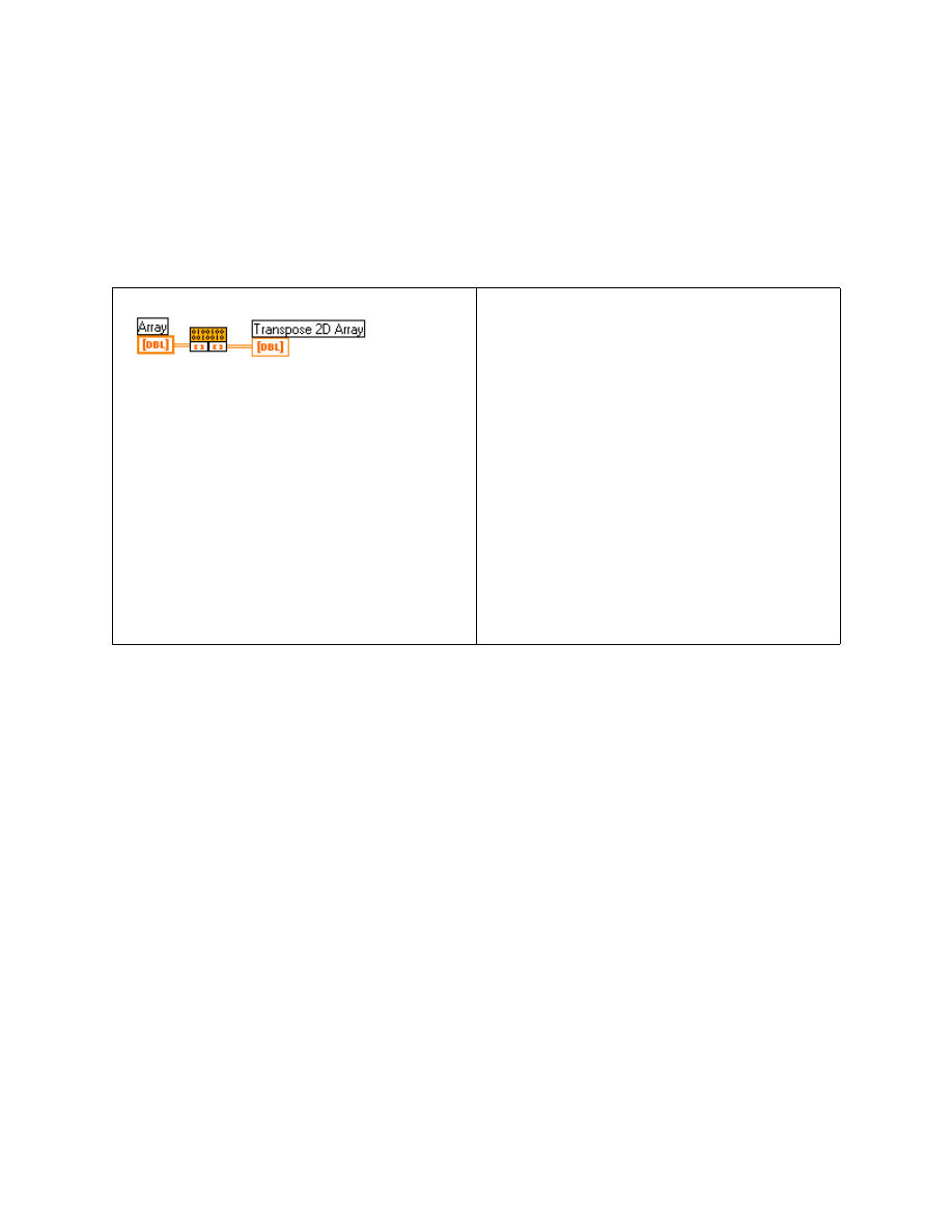
Module 3 Lesson 3 Exercises
©
National Instruments Corporation
3-3-11
LabVIEW Advanced I Course Manual
Exercise 3-5
Objective:
To examine code that shows how LabVIEW passes a multidimensional array
to a CIN.
You will examine a CIN that transposes a 2D array.
Block Diagram and Initial .C File
1. Use the Display Text File VI to open and display the file
Transpose.c
in the
LV_AdvI\SOURCES
directory.
2. Notice the following about the source code.
a. LabVIEW passes the handle that points to the array to be transposed.
b. A temporary array is allocated using the LabVIEW memory
manager function DSNewPtr and deallocated using DSDisposePtr.
c. The transposition is performed, and temp_array holds the transposed
array.
d. The MoveBlock function is used to transfer the transpose array to
the input array.
/*
* Transpose.c -> returns the transpose of the given 2D Array
* Parameters -> Array -> Handle to an array of float64 numbers
*/
#include "extcode.h"
/*
* typedefs
*/
/*
* CIN source file
*/
#include "extcode.h"
/*
* typedefs
*/
typedef struct {
int32 dimSizes[2];
int16 arg1[1];
} TD1;
typedef TD1 **TD1Hdl;
CIN MgErr CINRun(TD1Hdl Array);
CIN MgErr CINRun(TD1Hdl Array) {
/* ENTER YOUR CODE HERE */
return noErr;
}

Module 3 Lesson 3 Exercises
LabVIEW Advanced I Course Manual
3-3-12
©
National Instruments Corporation
typedef struct {
int32 dimSizes[2];
float64 arg1[1];
} TD1;
typedef TD1 **TD1Hdl;
CIN MgErr CINRun(TD1Hdl Array);
CIN MgErr CINRun(TD1Hdl Array) {
int32 i, j, nrows, ncols;
float64 *fElmnt;
float64 *temp_array = NULL;
MgErr mgError = noErr;
nrows = (*Array)->dimSizes[0];
ncols = (*Array)->dimSizes[1];
/* Check to see if array has been allocated by LabVIEW */
if(!(fElmnt = (*Array)->arg1)){
mgError = mFullErr;
goto out;
}
/* Allocate temporary memory for transposed array */
if (!(temp_array = (float64 *) DSNewPtr(nrows * ncols * sizeof(float64))))
mgError = mFullErr;
goto out;
/* Perform the transposition */
for (i=0; i< nrows ; i++)
for (j=0; j < ncols ; j++)
temp_array[i + nrows * j] = fElmnt[i * ncols + j];
/* Transposed array has rows and columns interchanged */
(*Array)->dimSizes[0] = ncols;
(*Array)->dimSizes[1] = nrows;
/* Copy the transposed array back to the user's array */
MoveBlock (temp_array, (*Array)->arg1, (nrows * ncols) *sizeof(float64));
/* Dispose off temporary memory */
DSDisposePtr(temp_array);
out:
return mgError;
}

Module 3 Lesson 3 Exercises
©
National Instruments Corporation
3-3-13
LabVIEW Advanced I Course Manual
3. Open Transpose.vi from
cinclass.llb
.
4. If you have access to a compiler, compile the source code using the
Visual C++ compiler. Load the code resource into the CIN by popping
up on the CIN and selecting
Transpose.lsb
.
5. Enter an array in the Array control of the VI. Run the VI. You will
observe that the Transpose CIN transposes the array in the Array control
and returns the result in Transpose 2D Array. After you have finished,
save the VI as Transpose.vi in
cinclass.llb
and close the VI.
End of Exercise 3-5
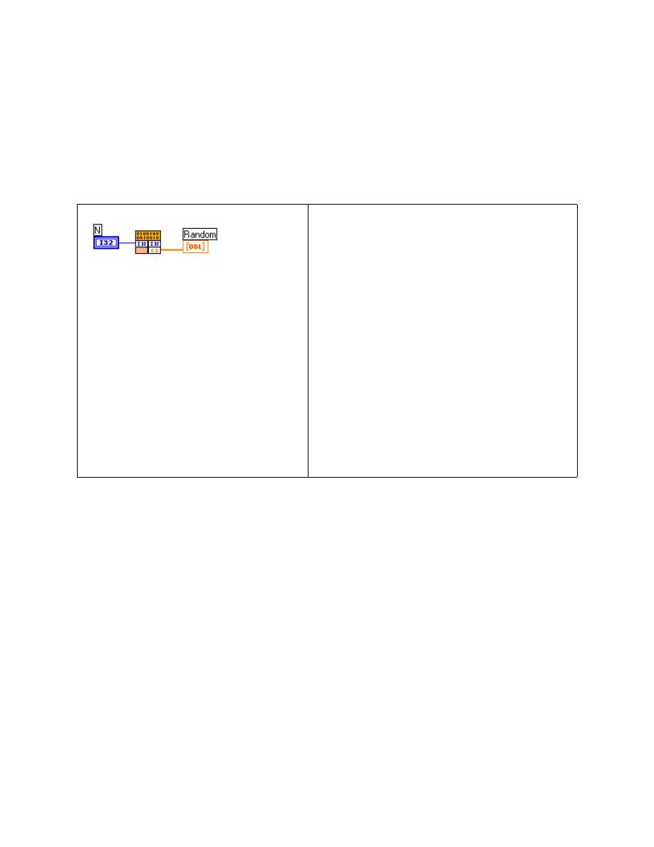
Module 3 Lesson 3 Exercises
LabVIEW Advanced I Course Manual
3-3-14
©
National Instruments Corporation
Exercise 3-6
Objective:
To examine code that shows how to resize an array handle within a code resource.
You will examine a CIN that creates an array with random double-precision
numbers. The array is allocated within the code resource.
Block Diagram and Initial .C File
1. Use the Display Text File VI to open and display the file
Random.c
in
the
LV_AdvI\SOURCES
directory.
2. Notice the following in the source code.
a. The handle is resized within the code resource. The handle then
points to a block of memory with a specific size, dimension, and data
type.
b. Even with a successful reallocation, the output array size variable
must be updated.
/*
* Random.c -> returns an array of random numbers
* parameters: Input : n -> pointer to the size of the array
* Output : random -> handle to an array of float64 numbers
*/
#include "extcode.h"
/*
* typedefs
*/
/*
* CIN source file
*/
#include "extcode.h"
/*
* typedefs
*/
typedef struct {
int32 dimSize;
float64 arg1[1];
} TD1;
typedef TD1 **TD1Hdl;
CIN MgErr CINRun(int32 *N, TD1Hdl
Random);
CIN MgErr CINRun(int32 *N, TD1Hdl Random)
{
/* ENTER YOUR CODE HERE */
return noErr;
}

Module 3 Lesson 3 Exercises
©
National Instruments Corporation
3-3-15
LabVIEW Advanced I Course Manual
typedef struct {
int32 dimSize;
float64 arg1[1];
} TD1;
typedef TD1 **TD1Hdl;
CIN MgErr CINRun(int32 *n, TD1Hdl random);
CIN MgErr CINRun(int32 *n, TD1Hdl random) {
int32 i;
MgErr cinErr = noErr;
if(cinErr = SetCINArraySize((UHandle)random,1L,*n))
goto out;
/* resize the output array */
(*random)->dimSize = *n;/* set the output size */
for(i=0; i<*n; i++)
/* write the output elements */
RandomGen(&((*random)->arg1[i]));
out:
return cinErr;
}
3. Open Random.vi from
cinclass.llb
.
4. If you have access to a compiler, compile the source code using the
Visual C++ compiler. Load the code resource into the CIN by popping
up on the CIN and selecting
Random.lsb
.
5. Enter a number in the control N on the front panel. Run the VI. You will
observe that the Random CIN generates an array of N elements in the
array Random. After you have finished, save the VI as Random.vi in
cinclass.llb
and close the VI.
End of Exercise 3-6
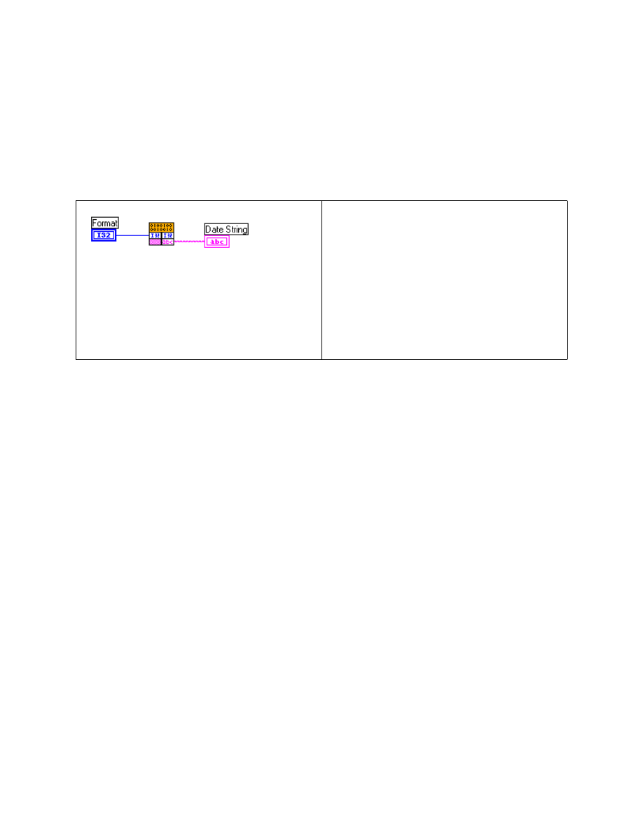
Module 3 Lesson 3 Exercises
LabVIEW Advanced I Course Manual
3-3-16
©
National Instruments Corporation
Exercise 3-7
Objective:
To examine code that shows how to resize a string handle within a code resource.
You will examine a CIN that returns the current date string in an optional
format. The string is allocated within the code resource.
Block Diagram and Initial .C File
1. Use the Display Text File VI to open and display the file
DateCStr.c
in the
LV_AdvI\SOURCES
directory.
2. Notice the following in the source code.
a. The handle is resized within the code resource. The handle then
points to a block of memory with a specific size, dimension, and data
type.
b. The memory manipulation uses a reference to the handle position in
the argument list (PARAMETER).
c. Even with a successful reallocation, the output string length variable
must be updated.
/* DateCStr.c -> the date in a specific format
* parameters: Input :
Format -> pointer to the format
*
Output : Date_String-> handle to the string
*/
#include "extcode.h"
#define DIMENSION 1L
CIN MgErr CINRun(int32 *Format, LStrHandle Date_String);
CIN MgErr CINRun(int32 *Format, LStrHandle Date_String) {
uInt32
time;
int32
size;
CStr
TempStr;
MgErr
cinErr = noErr;
/*
* CIN source file
*/
#include "extcode.h"
CIN MgErr CINRun(int32 *Format,
LStrHandle Date_String);
CIN MgErr CINRun(int32 *Format,
LStrHandle Date_String) {
/* ENTER YOUR CODE HERE */
return noErr;
}

Module 3 Lesson 3 Exercises
©
National Instruments Corporation
3-3-17
LabVIEW Advanced I Course Manual
time = TimeInSecs();
/* get the times in secs */
TempStr = DateCString(time, *Format); /* get the C string */
size = StrLen(TempStr);
/* get the size of the C string */
/* set the string handle size */
if(cinErr = NumericArrayResize(uB,DIMENSION,(UHandle*)&Date_String,size))
goto out;
LStrLen(*Date_string) = size;
/* update the string size */
MoveBlock(TempStr,LStrBuf(*Date_String),size); /* copy the data buffer */
out:
return cinErr;
}
3. Open DateCStr.vi from
cinclass.llb
.
4. If you have access to a compiler, compile the source code using the
Visual C++ compiler. Load the code resource into the CIN by popping
up on the CIN and selecting
DateCStr.lsb
.
5. Chose the three different formats 0, 1, 2 and run the VI. You will
observe that the current date is displayed in different formats. After you
have finished, save the VI as DateCStr.vi in
cinclass.llb
and close
the VI.
End of Exercise 3-7

Module 3 Lesson 3 Exercises
LabVIEW Advanced I Course Manual
3-3-18
©
National Instruments Corporation
Additional Exercises
3-8
Create a CIN that sorts an incoming random array of
double-precision numbers.
Use the following function from the support manager:
void QSort (Ptr arrayp,int32 NumOfElements,
int32 ElementSize,(int32(*)(void*, void*)
Compare());
An additional compare routine is required and should return a
negative number if a is less than b, a zero if a is equal to b, and a
negative number if a is greater than b. For this exercise, the
comparison function prototype looks like the following code:
int32 Compare(float64 *a, float64 *b);
Create the
Sort
directory to save all your work. Name your VI and
source code files Sort.vi and
Sort.c
, respectively.
3-9
Create a CIN that concatenates two strings and returns a new
concatenated string in place of the first string. Create the
StrCat
directory to save all your work. Name your VI and source code files
StrCat.vi and
StrCat.c
, respectively.
3-10
Create a CIN that sums the elements of each row in a 2D array and
returns the sum in a 1D array. The sum of the first row should be
returned in element 0 of the 1D array, the sum of the second row in
element 1, and so on. For example, a 5 x 3 (row x column) array
should return a five-element 1D array.
Create the
AddRows
directory to save all your work. Name your VI
and source code files AddRows.vi and
AddRows.c
, respectively.
©
National Instruments Corporation
3-4-1
LabVIEW Advanced I Course Manual
Module 3
Lesson 4
Exercises
Exercise 4-1
Objective:
To examine code that implements and calls an external subroutine. (If you have
access to a compiler, build the VI and code resource).
You will examine an external subroutine’s source code that finds the
maximum and minimum values in the input sequence. You will also
examine a CIN that calls this external subroutine.
Block Diagram and Initial .C File
1. MxMn.vi already is built for you. Open it and examine the block
diagram.
/*
* MxMn.c: CIN source file
*/
#include "extcode.h"
/*
* typedefs
*/
typedef struct {
int32 dimSize;
float64 arg1[1];
} TD1;
typedef TD1 **TD1Hdl;
CIN MgErr CINRun(TD1Hdl Array, float64
*Max, float64 *Min);
CIN MgErr CINRun(TD1Hdl Array, float64
*Max, float64 *Min) {
/* ENTER YOUR CODE HERE */
return noErr;
}

Module 3 Lesson 4 Exercises
LabVIEW Advanced I Course Manual
3-4-2
©
National Instruments Corporation
2. Use the Display Text File VI to open and display the file
MaxMin.c
in
the
LV_AdvI\SOURCES
directory.
MaxMin.c
is an external subroutine
that finds the maximum and minimum values in the input sequence.
MaxMin(float64 *Array, int32 size,float64 *max,float64 *min)
Array
points to the data buffer to be scanned.
size
sets the number of
elements to be scanned.
max
and
min
are the maximum and minimum
values in the sequence, respectively.
The source code for
MaxMin.c
is shown below:
/* MaxMin.c: External Sub-routine that finds the maximum and minimum values in
* the input sequence.
*/
#include "extcode.h"
/* prototype*/
void LVSBMain(float64 *Array, int32 size, float64 *max, float64 *min);
/* subroutine*/
void LVSBMain(float64 *Array, int32 size, float64 *max, float64 *min)
{
int32 i;
*min=*max=Array[0];
for(i=1;i < size; i++){
if(Array[i] > *max)
*max = Array[i];
if (Array[i] < *min)
*min = Array[i];
}
}
3. Note the use of the
LVSBMain()
function to write the external
subroutine. Also, the CIN header file
extcode.h
has been included.
4. Create the
MaxMin.lvm
file for the Visual C++ compiler as shown
below:
name = MaxMin
type = LVSB
!include $(CINTOOLSDIR)\ntlvsb.mak
5. Compile your external subroutine by issuing the command
nmake /f MaxMin.lvm
The external subroutine
MaxMin.lsb
will be created.
6. Use the Display Text File VI to open and display the file
MxMn.c
from
the
LV_AdvI\sources
directory. Examine the source code. Notice that
the external
MaxMin
is called.

Module 3 Lesson 4 Exercises
©
National Instruments Corporation
3-4-3
LabVIEW Advanced I Course Manual
/* MxMn.c -> Calls the MaxMin analysis external
* parameters: Input: Array -> handle to an array of float64
* Output: Max -> pointer to a float64 number
* Min -> pointer to a float64 number
*/
#include "extcode.h"
/*
* typedefs
*/
typedef struct {
int32 dimSize;
float64 arg1[1];
} TD1;
typedef TD1 **TD1Hdl;
/* External prototype */
extern void MaxMin (float64 *x, int32 n, float64 *max, float64 * min);
CIN MgErr CINRun(TD1Hdl Array, float64 *max, float64 *min);
CIN MgErr CINRun(TD1Hdl Array, float64 *max, float64 *min) {
int32 n;
float64 *arrayPtr;
n= (*Array)->dimSize; /* n= number of elements*/
arrayPtr = (*Array)->arg1; /* arrayPtr = buffer */
MaxMin(arrayPtr, n, max, min); /* Call external */
return noErr;
}
7. Create the
MxMn.lvm
file for the Visual C++ compiler as shown below:
name=MxMn
type=CIN
subrNames = MaxMin
!include <$(CINTOOLSDIR)\ntlvsb.mak>
8. Compile
MxMn.lsb
if you have access to a compiler. MxMn.vi already
has
MxMn.lsb
loaded so you can run the VI.
9. Enter different values in Array and run the VI. Minimum and maximum
values in the input sequence will be displayed. Run the VI several times
by entering different values.
10. After you are finished, close the VI.
End of Exercise 4-1
Module 3 Lesson 4 Exercises
LabVIEW Advanced I Course Manual
3-4-4
©
National Instruments Corporation
Exercise 4-2
Objective:
To examine code that shows how a CIN uses code global variables.
(If you have
access to a compiler, build the VI and code resource.)
You will examine a CIN that reads or writes a Boolean code global variable.
The Boolean code global will control the execution of two independent
loops within the same VI.
Block Diagram and Initial .C File
1. Use the Display Text File VI to open and display the file
CodeGlob.c
in the
LV_AdvI\SOURCES
directory.
2. Examine the source code. The boldfaced code is the code particular to
this CIN. As a general rule, you should initialize global variables before
reading from them. If global variables are not initialized, they return an
unknown value. You should initialize the code globals only once, in the
CINLoad
routine.
/*
* CodeGlob.c -> updates a code global boolean variable
* parameters: Input: Mode -> pointer to a Boolean
* I/O: Data_In -> pointer to a Boolean
*/
#include "extcode.h"
LVBoolean GSTOP;
CIN MgErr CINRun(LVBoolean *Mode, LVBoolean *Data_In);
CIN MgErr CINRun(LVBoolean *Mode, LVBoolean *Data_In) {
if (*Mode == LVTRUE ) {
GSTOP = *Data_In; /* update global */
}
*Data_In = GSTOP; /* update output */
return noErr;
}
CIN MgErr CINLoad(RsrcFile rf) {
GSTOP = LVTRUE; /* initialize global to TRUE */
return noErr;
}
/*
* CIN source file
*/
#include "extcode.h"
CIN MgErr CINRun(LVBoolean *Mode, LVBoolean
*Data_In);
CIN MgErr CINRun(LVBoolean *Mode, LVBoolean
*Data_In) {
/* ENTER YOUR CODE HERE */
return noErr;
}
Module 3 Lesson 4 Exercises
©
National Instruments Corporation
3-4-5
LabVIEW Advanced I Course Manual
3. Compile the code and create
CodeGlob.lsb
, if you have access to a
compiler.
4. Open the Display Random Numbers VI in
cinclass.llb
. This VI
uses CodeGlob.vi as a subVI. The VI front panel and block diagram are
shown above.
The VI generates two different random numbers and displays them on
two waveform charts. The VI uses two separate While Loops and a
single switch to stop the execution of both loops.
5. Run the VI. CodeGlob.vi is a subVI that passes the value of the Stop
switch from one loop to the other with no wire dependency. Notice that
the algorithm is possible because both nodes refer to the same Boolean
global variable. Also, notice that the VI does not initialize the
CodeGlob subVI; this occurs in the CINLoad routine.
End of Exercise 4-2
Module 3 Lesson 4 Exercises
LabVIEW Advanced I Course Manual
3-4-6
©
National Instruments Corporation
Exercise 4-3
Objective:
To examine code that shows how LabVIEW uses a CIN data space global variable.
(If you have access to a compiler, build the VI and code resource.)
You will examine a CIN that takes a number and returns the average of that
number and the previous number passed to it. The VI containing the CIN is
reentrant. For each reference to the code in memory, you will have a
different set of globals.
Block Diagram and Initial .C File
1. Use the Display Text File VI to open and display the file
DataGlob.c
located in the
LV_AdvI\SOURCES
directory.
2. Examine the source code shown below and notice that a handle for the
global variable is allocated in
CINInit
and stored in the CIN data space
storage using
SetDSStorage
. When LabVIEW calls the
CINInit
,
CINDispose
, or
CINRun
routines, it ensures that
GetDSStorage
and
SetDSStorage
return the 4-byte CIN data space value for that node or
CIN data space.
To access that data, use
GetDSStorage
to retrieve the handle and
dereference the appropriate fields (see the code for
CINRun
). Finally,
you need to dispose of the handle in your
CINDispose
routine.
/* DataGlob.c -> takes the average of all the numbers passed to * the CIN
* parameters: Input: number -> pointer to a float64 number
* Output: average -> pointer to a float64 number
*/
#include "extcode.h"
typedef struct {
float64 total;
int32 numElements;
} dsGlobalStruct;
CIN MgErr CINRun(float64 *Number, float64 *Average);
/*
* CIN source file
*/
#include "extcode.h"
CIN MgErr CINRun(float64 *Number, float64
*Average);
CIN MgErr CINRun(float64 *Number, float64 *Average)
{
/* ENTER YOUR CODE HERE */
return noErr;
}

Module 3 Lesson 4 Exercises
©
National Instruments Corporation
3-4-7
LabVIEW Advanced I Course Manual
/* subroutines */
CIN MgErr CINInit() {
dsGlobalStruct **dsGlobals;
if(!(dsGlobals = (dsGlobalStruct**)DSNewHandle(sizeof(dsGlobalStruct))))
return mFullErr; /* if 0, ran out of memory */
(*dsGlobals)->numElements = 0; /* initialize the globals */
(*dsGlobals)->total = 0.0;
SetDSStorage((int32)dsGlobals); /* set the data space */
return noErr;
}
CIN MgErr CINDispose() {
dsGlobalStruct **dsGlobals;
dsGlobals = (dsGlobalStruct **)GetDSStorage(); /* get the data space */
if(dsGlobals)
DSDisposeHandle(dsGlobals); /* dispose global handle */
return noErr;
}
CIN MgErr CINRun(float64 *Number, float64 *average) {
dsGlobalStruct **dsGlobals;
dsGlobals = (dsGlobalStruct **)GetDSStorage(); /* get the data space */
if (dsGlobals) {
(*dsGlobals)->numElements ++; /* new element */
(*dsGlobals)->total += *Number; /* new total */
*average = (*dsGlobals)->total / (*dsGlobals)->numElements;
}
return noErr;
3. Open the Display Averages VI located in
cinclass.LLB
. This VI uses
DataGlob.vi as a subVI. It generates and plots the running average of
randomly generated points. The front panel and block diagram are
shown on the next page.
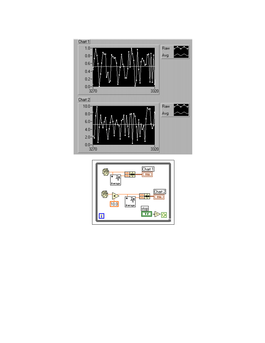
Module 3 Lesson 4 Exercises
LabVIEW Advanced I Course Manual
3-4-8
©
National Instruments Corporation
4. Run the VI. The VI generates the averages using two different calls to
the DataGlob.vi subVI. Because it is reentrant, each call to the CIN uses
its own data space globals.
5. Notice that the algorithm is possible because both nodes refer to the
different global variables. Also notice that the VI does not use an
initialization node. The global is initialized in the
CINInit
routine of
the code resource.
6. Disable the reentrancy option of the DataGlob.vi subVI. Open its front
panel. From the pop-up icon pane menu, choose VI Setup.... Click in the
Reentrant Execution box to disable it.

Module 3 Lesson 4 Exercises
©
National Instruments Corporation
3-4-9
LabVIEW Advanced I Course Manual
7. Run Display Averages.vi again. Notice that both charts display
incorrect averages as the data space is being shared. Some of the data
displayed on Chart 1 is used in calculating the average for Chart 2, and
vice versa.
8. After you have finished running the VI, close the VI.
End of Exercise 4-3
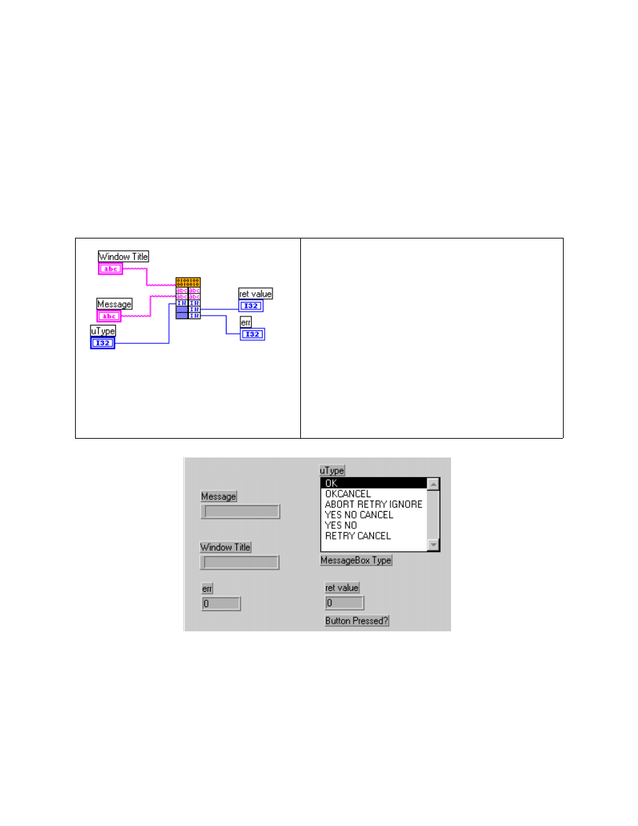
Module 3 Lesson 4 Exercises
LabVIEW Advanced I Course Manual
3-4-10
©
National Instruments Corporation
Exercise 4-4 (WIN32 only)
Objective:
To examine code that shows how to call a WIN32 system DLL from a CIN.
You will examine a CIN that calls a Windows DLL to display a dialog box.
The DLL calls the Windows Message Box function, which displays a
window containing a specified message. This function returns after you
press a button in the window.
Block Diagram and Initial .C File
1. Use the Display Text File VI to open and display the file
Messgdll.c
located in the
LV_AdvI\SOURCES
directory. This CIN calls the
user32.dll
file.
/*
* CIN Source File : Messgdll.c
* Parameters: Inputs: Window_Title -> LabVIEW string handle
* Message -> LabVIEW string handle
/*
* CIN source file
*/
#include "extcode.h"
CIN MgErr CINRun(LStrHandle
Window_Title, LStrHandle Message, int32
*uType, int32 *ret_value, int32 *err);
CIN MgErr CINRun(LStrHandle
Window_Title, LStrHandle Message, int32
*uType, int32 *ret_value, int32 *err) {
/* ENTER YOUR CODE HERE */
return noErr;
}

Module 3 Lesson 4 Exercises
©
National Instruments Corporation
3-4-11
LabVIEW Advanced I Course Manual
* UType: unsigned 32-bit integer value
* Output: ret_value-> 32-bit integer value
*/ err->
#include "extcode.h"
#include <windows.h>
CIN MgErr CINRun(LStrHandle Window_Title, LStrHandle Message, uInt32 *uType,
int32 *ret_value, int32 *err);
CIN MgErr CINRun(LStrHandle Window_Title, LStrHandle Message, uInt32 *uType,
int32 *ret_value, int32 *err) {
typedef int32 (WINAPI *MYPROC)uInt32, CStr, CStr, uInt32);
HINSTANCE hinstLib;
MYPROC ProcAdd;
char *messageCStr = NULL, *WinTitleCStr=NULL;
MgErr cinErr = noErr;
hinstLib = LoadLibrary("user32.dll");
if(hinstLib != NULL) {
ProcAdd = (MYPROC) GetProcAddress(hinstLib, "MessageBoxA");
}
else{
*err=1; /* LoadLibrary failed */
goto out;
}
if(!(messageCStr = DSNewPtr(LStrLen(*Message)+1))){
cinErr=mFullErr;
goto out;
}
if(!(WinTitleCStr = DSNewPtr(LStrLen(*Window_Title)+1))){
cinErr=mFullErr;
goto out;
}
SPrintf(messageCStr, (CStr) "%P", *Message);
SPrintf(WinTitleCStr, (CStr) "%P", *Window_Title);
if(ProcAdd != NULL){
*ret_value=(ProcAdd)(NULL, messageCStr, WinTitleCStr, *uType);
if(*ret_value==0)
cinErr=mFullErr;
}
else
*err=2; /* GetProcAddress Failed */
out:
if (messageCStr)
DSDisposePtr(messageCStr);
if(WinTitleCStr)
DSDisposePtr(WinTitleCStr);
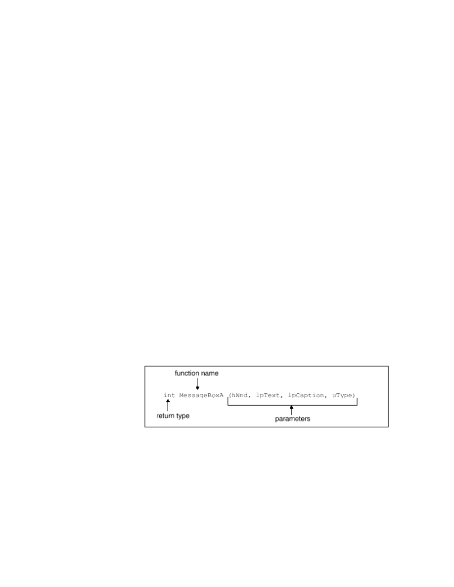
Module 3 Lesson 4 Exercises
LabVIEW Advanced I Course Manual
3-4-12
©
National Instruments Corporation
if (hinstLib)
FreeLibrary(hinstLib);
return cinErr;
}
2. Examine the code above. Notice that this example does not pass a full
path to the
LoadLibrary
function. The DLL is located in the
windows\system
directory.
The CIN first loads the library and then gets the address of the DLL
entry point. Calling
GetProcAddress
for a DLL requests the address
of the
MessageBoxA
function.
Notice that at each stage of calling the DLL, the code checks for errors
and returns an error code if it fails.
Also notice that LabVIEW strings are different from C strings. C strings
are terminated with a null character. LabVIEW strings are not null
terminated; instead, they begin with a 4-byte value that indicates the
length of the string. Because the DLL expects C strings, this example
creates temporary buffers for the C strings using
DSNewPtr
, and then
uses
SPrintf
to copy the LabVIEW string into the temporary buffers.
Finally, the CIN calls the
MessageBoxA
function by passing the
appropriate parameters.
*ret_value=(ProcAdd)(NULL, messageCStr,
WinTitleCStr, *uType);
3. To find information about the
MessageBoxA
function, consult a
Windows programming manual that covers the WIN32 API and
Windows “include” files (such as
windows.h
,
windowsx.h
, and
winuser.h
). The following is a description of the
MessageBoxA
function:
Return Type
The return type for the function is defined as a 32-bit signed integer.
The WIN32 API lists the names of the constants for the possible return
values for the
MessageBoxA
function. The actual values of these constants
are stored in the
winuser.h
file.

Module 3 Lesson 4 Exercises
©
National Instruments Corporation
3-4-13
LabVIEW Advanced I Course Manual
IDOK
1
IDCANCEL
2
IDABORT
3
IDRETRY
4
IDIGNORE
5
IDYES
6
IDNO
7
If the message box cannot be created due to a lack of memory, zero will be
returned.
Parameters
The Microsoft WIN32 Programmer’s Reference lists the data types of each
of the parameters to the
MessageBoxA
function; the actual type definitions
are all found in the
winuser.h
file.
HWND
Identifies the owner or parent window of the
message box to be created. If this parameter is
NULL, the message box has no owner window.
The HWND data type is a 32-bit unsigned integer
as defined in
winuser.h
and
windows.h
.
Essentially, we can identify which window the
message box “belongs to” by passing a valid
value for
hWnd
. However, it is not necessary to
define a parent for this window, so we will assign
“no parent,” or 0.
LPCSTR lpText
A 32-bit pointer to a constant character string and
is defined as a C-style (NULL terminated) string.
This string contains the text we want to display in
the window.
LPCSTR lpCaption
A C-style constant character string containing the
desired name to appear in the title bar of the
window.
UINT uType
An unsigned 32-bit integer value. It determines
which type of message box is displayed. The
Windows API lists the names of valid constants
that may be passed to this function, and
winuser.h
will contain the actual hex values. In
this example, we will create a dialog box with
“Yes,” “No,” and “Cancel” buttons. The name of
the constant is
MB_YESNOCANCEL
, which is
defined to have the value
3
in
winuser.h
. We
will pass this value for the uType parameter.
Module 3 Lesson 4 Exercises
LabVIEW Advanced I Course Manual
3-4-14
©
National Instruments Corporation
The other types of message boxes and their corresponding uTypes are:
Note
Do not use values for uType other than those listed in the WIN32 API or
winuser.h. You could cause errors in Windows 95/NT/98 that may result in a
crash or incorrect behavior.
4. Open Messgdl.vi. Enter different values for the Message Box Type and
run the VI.
5. Close the VI after you have finished. Do not save any changes.
End of Exercise 4-4
Message Box Button Type
uType (hex)
OK
0
OK CANCEL
1
ABORT RETRY IGNORE
2
YES NO CANCEL
3
YES NO
4
RETRY CANCEL
5
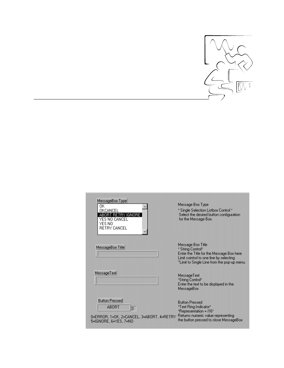
©
National Instruments Corporation
3-5-1
LabVIEW Advanced I Course Manual
Module 3
Lesson 5
Exercises
Exercise 5-1
Objective:
To call the MessageBoxA function in user32.dll.
You will create and run a VI that contains a call to the MessageBoxA
function in
user32.dll
. You will learn how to configure the Call Library
Function to call
user32.dll
, which resides in the
\WINDOWS\SYSTEM
directory. You have already called this function in a previous exercise from
a CIN. You will observe how much easier it is to call a function in a DLL
via the Call Library function than calling it from a CIN.
Front Panel
Module 3 Lesson 5 Exercises
LabVIEW Advanced I Course Manual
3-5-2
©
National Instruments Corporation
1. Create the front panel as shown. You do not need to include the
comments, because they are displayed only to explain the controls and
indicators.
2. In this example, you will create a message box of type ABORT RETRY
IGNORE. The description of the MessageBoxA function from
winuser.h
supplies you with the information you need to call the
function.
Return Type
The return type for the function is defined as a 32-bit signed integer:
int
32 bit signed integer
The Win32 API lists the names of the constants for the possible return
values for the MessageBoxA function. The actual values of these
constants are stored in the
winuser.h
file. In this example, the possible
return values are IDABORT, IDRETRY, and IDIGNORE, which have
the decimal values 3, 4, and 5, respectively. If the message box cannot
be created due to a lack of memory, zero will be returned.
Parameters
The Microsoft Win32 Programmer’s Reference lists the data types of each
of the parameters to the MessageBoxA function. The actual type definitions
are all found in the
winuser.h
file.
HWND
hWnd
Identifies the owner or parent window of the
message box to be created. If this parameter
is NULL, the message box has no owner
window. The HWND data type is a 32-bit
unsigned integer as defined in
winuser.h
and
windows.h
. Essentially, you can
identify which window the message box
“belongs to” by passing a valid value for
hWnd. However, it is not necessary to define
a parent for this window, so you will assign
“no parent,” or NULL. The constant NULL is
defined to be zero.
function name
int MessageBoxA (hWnd, lpText, lpCaption, uType)
return type
parameters

Module 3 Lesson 5 Exercises
©
National Instruments Corporation
3-5-3
LabVIEW Advanced I Course Manual
LPCSTR
lpText
The LPCSTR type is a 32-bit pointer to a
constant character string and is defined as a
C-style (NULL terminated) string. This
string contains the text you want to display in
the window.
LPCSTR
lpCaption
This parameter is a C-style constant character
string containing the desired name to appear
in the title bar of the window.
UINT
uType
The UINT data type is defined as an unsigned
32-bit integer value. It determines which type
of message box is displayed. The Windows
API lists the names of valid constants that
may be passed to this function, and
winuser.h
will contain the actual decimal
values. Because you will create a dialog box
with ABORT, RETRY, and IGNORE buttons.
The name of the constant is
MB_ABORTRETRYIGNORE, which is
defined to have the value 2 in
winuser.h
.
You will pass this value for the uType
parameter. The other types of message boxes
and their corresponding uType are:
Note
Do not use values for uType other than those listed in the Win32 API or
winuser.h. You could cause errors in Windows 95/NT that may result in a
crash or incorrect behavior.
The calling convention for the MessageBoxA function can be found in
the
winuser.h
file. Searching in
winuser.
h for MessageBoxA, you
find that the function is preceded by the word WINAPI. This is defined
as
_stdcall
in
windef.h
.
Message Box Button Type
uType
OK
0
OK CANCEL
1
ABORT RETRY IGNORE
2
YES NO CANCEL
3
YES NO
4
RETRY CANCEL
5

Module 3 Lesson 5 Exercises
LabVIEW Advanced I Course Manual
3-5-4
©
National Instruments Corporation
Note
In Win32, you can use _cdecl and _stdcall calling conventions. The calling
convention determines the order in which arguments passed to the functions
are pushed onto the stack. It also determines which function—calling or
called—removes the arguments from the stack.
The Default (“stdcall”) calling convention is used to call Win32 API
functions. Parameters are passed by a function onto the stack from right
to left, and are passed by value unless a pointer or reference type is
passed. Function arguments are fixed, and a function prototype is
required. A called function pops its own arguments from the stack.
Functions using this calling convention return values the same way as
functions using the C calling convention. The C calling convention is
the default calling convention for C and C++ programs.
3. On the block diagram, create the Call Library Function. To view the
online help for this function, select Show Help from the Help menu and
move the cursor over the function icon. You can also obtain more
information about this function by selecting Online Help from the
pop-up menu. Note that at this point, only one set of terminals appears
on the function icon, and they are grayed out. After you configure the
Call Library Function for the DLL function you want to use, the
appropriate terminals will be available on the icon. Pop up on the Call
Library Function icon and select Configure... from the pop-up menu.
Finish configuration by referring to the following instructions:
a. Type
USER32.DLL
in the Library Name or Path box. You will not
need to type in the entire path to the DLL unless the DLL is stored
in a location that does not appear in the
PATH
variable in
AUTOEXEC.BAT
on Windows 95/98 and the System Control panel
on Windows NT or the LabVIEW VI Search Path.
Note
If you press <Enter> on the keyboard, the configuration window will close.
You can reopen it by selecting Configure... from the pop-up menu of the Call
Library Function icon or by double-clicking on it.
b. Next, click in the Function Name field and type the name of the
function: MessageBoxA. Function names in general are case
sensitive.
c. Let the VI run in the user interface thread. Do not mark it as
reentrant.
d. You do not need to change the value in the Calling Conventions box,
because the default convention is
_stdcall
.
e. At this point, you need to indicate what kind of data the
MessageBoxA function will return to LabVIEW when it has
finished. You know the return value of the function is a 32-bit integer
indicating which button was pressed in the dialog box. To set this,
use the Parameter and Type fields. Observe that the Parameter field
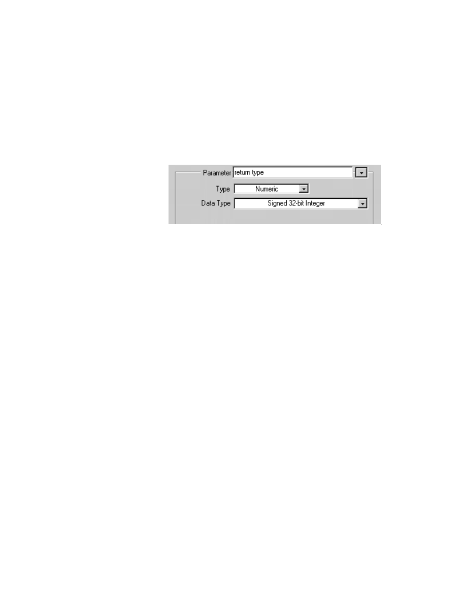
Module 3 Lesson 5 Exercises
©
National Instruments Corporation
3-5-5
LabVIEW Advanced I Course Manual
contains the text return type, and below this, you see that the Type is
set to Void. Because the MessageBoxA function returns a signed
32-bit integer value, select this data type for the Return value. To do
this, click on the selection box next to the Type field and select
Numeric from the pop-up list. You may also change the name of the
return type to something more descriptive, such as “button pressed.”
f.
After setting the return type to Numeric, you will see a new field
appear, called Data Type. In this case, you can change the data type
by popping up on the arrow. The default is Signed 32-bit Integer.
g. In addition to defining the return type of the function, we also must
define the four arguments to be passed to the function. The first
argument of the MessageBoxA function is the
hWnd
parameter,
which is an unsigned 32-bit integer. Click on the Add a Parameter
After button to add the first parameter. Then, select Unsigned
32-bit Integer from the Data Type menu. Because the function
expects the value, and not a pointer to the value, leave the Pass
setting unchanged. If you like, you can change the name of the
parameter from
arg1
to something more descriptive, such as
hWnd
.
h. From the definition of the MessageBoxA function, the second and
third arguments of the function are pointers to C-style strings. To add
a string to the parameter list as the second argument, first make sure
that the first argument appears in the Parameter box. You can select
an argument by using the selector to the right of the box containing
the parameter name. Click the Add a Parameter After button. To
set the type of the data to a pointer to a string, select String from the
Type menu. When you send a string to a function, you can select
whether the pointer to the string points to a C-style (string followed
by a NULL character), Pascal-style (string preceded by a length
byte) string, or as a LabVIEW string handle (four bytes of length
information followed by the string data). In this example, the default
setting (C String Pointer) is correct. Array and String options are
discussed in detail in Lesson 6, Writing DLLs.
i.
The third argument passed to this function is another string, which
contains the title of the message box window. Set up this argument
in the same way as the previous argument.
j.
Finally, you must add the uType parameter, which is an unsigned
32-bit integer. This is the value that determines which type of
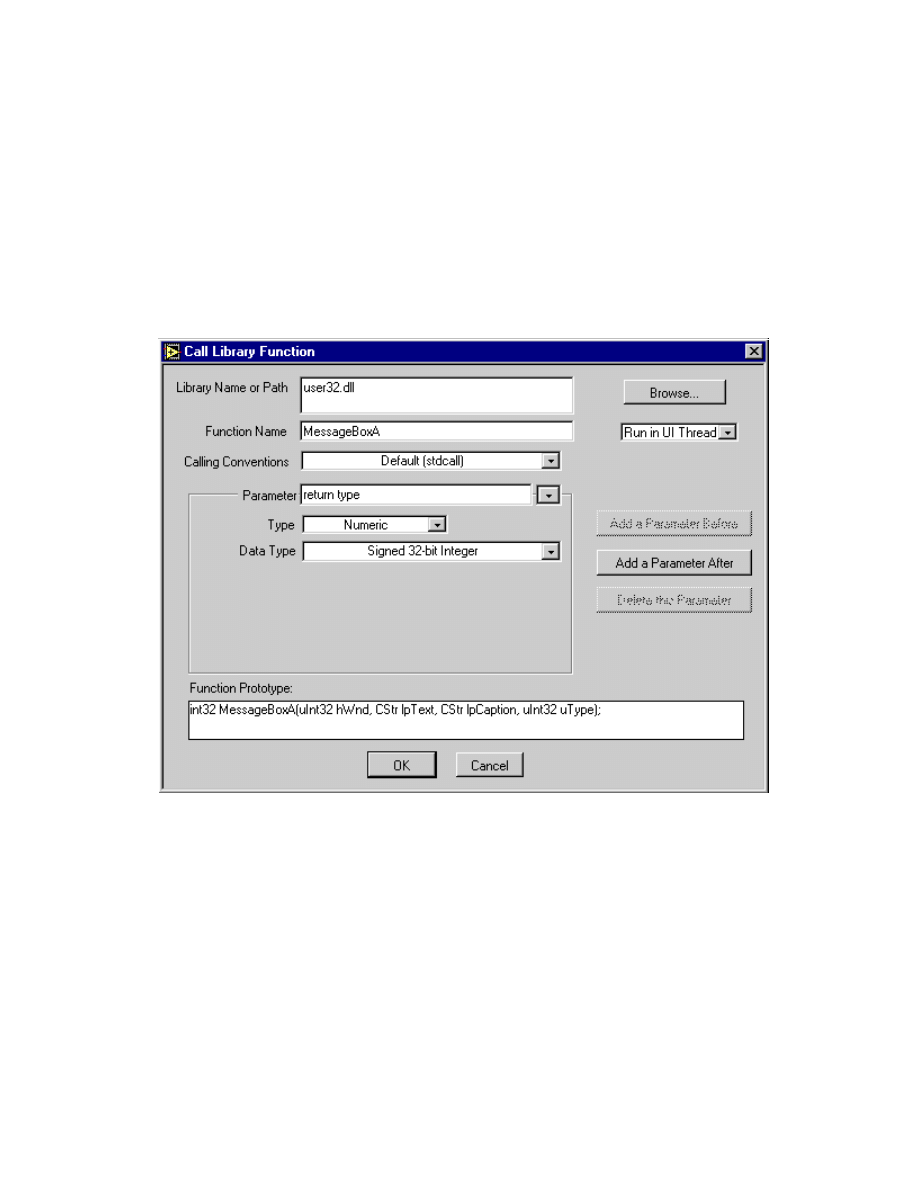
Module 3 Lesson 5 Exercises
LabVIEW Advanced I Course Manual
3-5-6
©
National Instruments Corporation
message box is displayed. When you have finished configuring the
Call Library Function, you can double-check if your configuration
is correct by comparing the Function Prototype displayed in the
configuration window to that obtained from the documentation of
the function. This will help you determine whether or not you are
passing the correct data types to the function. Note that LabVIEW
uses descriptive names for data types. For example, the int32 data
type describes a 32-bit signed integer in LabVIEW. In most
compilers, this data type is described as int. The fully configured
Call Library Function is shown below.
4. Check to see that you have completed the dialog box correctly by
studying the figure above. Click the OK button to close the
configuration window. Notice how terminals have been added to the
icon and the parameters of the function listed from left to right in the
function prototype match the data types appearing on the terminals of
the icon from top to bottom. The upper left input terminal is disabled
because the top output terminal is the return value of the function, not an
argument to the function.
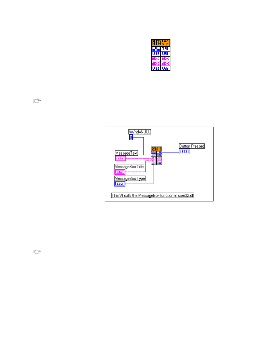
Module 3 Lesson 5 Exercises
©
National Instruments Corporation
3-5-7
LabVIEW Advanced I Course Manual
5. To complete the VI, build the diagram shown below. Remember to set
the representation of the numeric constants you connect to the Call
Library Function icon to the correct type.
Note
All input terminals to the Call Library Function must receive data.
Block Diagram
6. Once you have finished constructing the diagram, save your program
into
c:\exercises\LV_AdvI\dllclass.llb
as Message Box.vi
and run it. You will observe that the ABORT RETRY IGNORE dialog
box is displayed. Select other Message Box types, run the VI, and
observe that the DLL returns a numeric value representing the actual
button pressed.
Note
It is much easier to call a function in a DLL through the Call Library
Function node than from a CIN.
7. After you are done, close all VIs.
End of Exercise 5-1
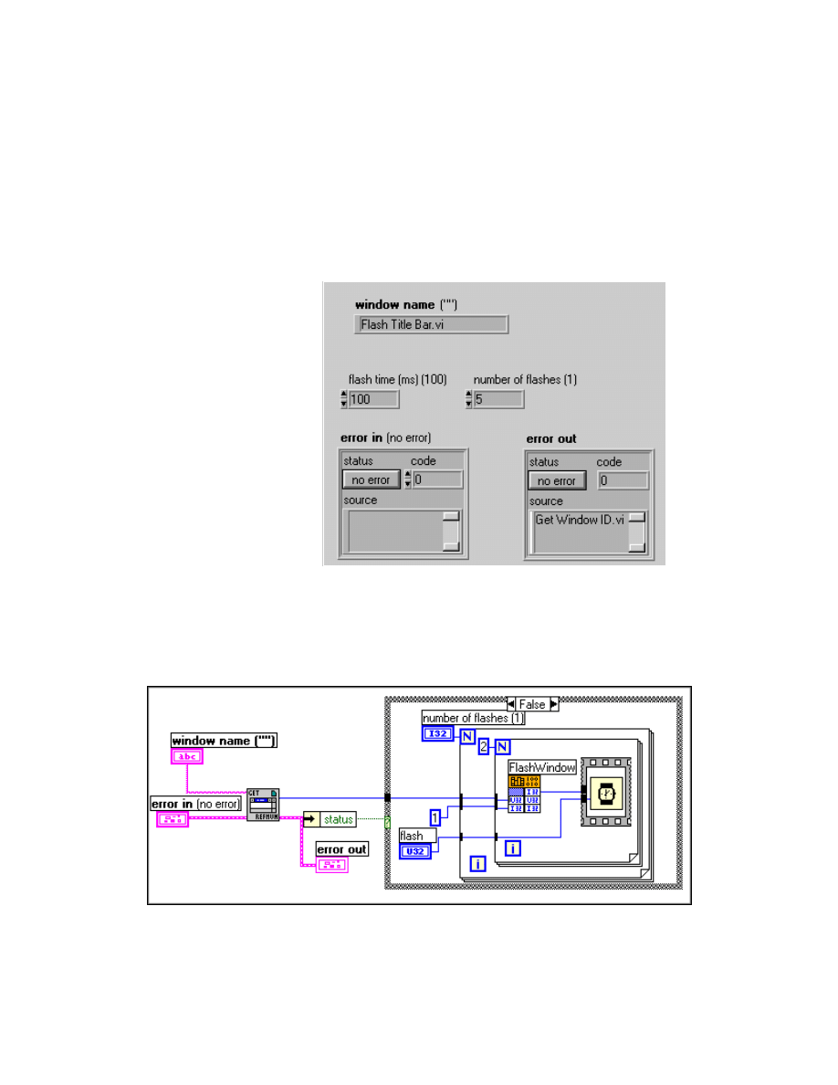
Module 3 Lesson 5 Exercises
LabVIEW Advanced I Course Manual
3-5-8
©
National Instruments Corporation
Exercise 5-2
Objective:
To call the FindWindowA and FlashWindow functions in user32.dll.
You will create and run a VI that contains calls to the FindWindowA and
FlashWindow functions. With these two functions, you will build a VI that
will flash the title bar of the named window.
Front Panel
1. Open Flash Title Bar.vi from
dllclass.llb
. The front panel of this
VI is already built for you.
Block Diagram
2. Build the block diagram as shown above. The TRUE case is empty. Get
Window Refnum.vi is already built for you. Open the VI from
dllclass.llb
and examine its block diagram.
Module 3 Lesson 5 Exercises
©
National Instruments Corporation
3-5-9
LabVIEW Advanced I Course Manual
Get Window Refnum.vi (Select a VI... menu in
dllclass.llb
) uses
the FindWindowA API function from
user32.dll
to retrieve a
window refnum identified by the window name. The following is an
explanation of the Call Library node configuration. The function
prototype for FindWindow as defined in
windows.h
is as follows:
return type
The return type for the function is defined as a 32-bit unsigned integer. The
return value identifies the window that has the specified window name by a
unique refnum.
parameters
The Microsoft Win32 Programmer’s Reference lists the data types of each of
the parameters to the FindWindow function; the actual type definitions are
all found in the
winuser.h
file.
LPCSTR lpClassName—Points to a null-terminated character string that
specifies the window’s class name. If lpClassName is NULL, all class
names match. In this case, we must pass a NULL to this parameter. In
LabVIEW, when you pass an empty string to a DLL, you do NOT pass a
NULL pointer—just a pointer to a 0-byte string. Because a NULL pointer
has a numeric value of zero, the easiest way to pass it is to send an integer
value of zero. Hence, you will pass a 0 as a long integer.
LPCSTR lpWindowName—Points to a null-terminated character string
that specifies the window name whose refnum is to be identified.
function name
HWND FindWindowA (lpClassName, lpWindowName)
return type
parameters
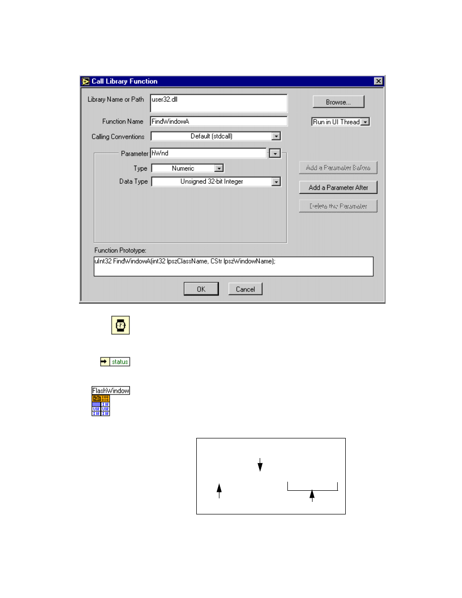
Module 3 Lesson 5 Exercises
LabVIEW Advanced I Course Manual
3-5-10
©
National Instruments Corporation
The configuration of the FindWindowA function is:
Wait ms function (Time & Dialog subpalette). In this exercise, this
function determines the time in milliseconds between which the window is
flashed.
Unbundle By Name function (Cluster subpalette). In this exercise, this
function extracts the value of the status Boolean.
Call Library function (Advanced subpalette). In this exercise, you will
configure this node to call the FlashWindow function in
user32.dll
.
The function prototype of FlashWindow as specified in
winuser.h
is:
function name
BOOL FlashWindow (hWnd, bInvert)
return type
parameters
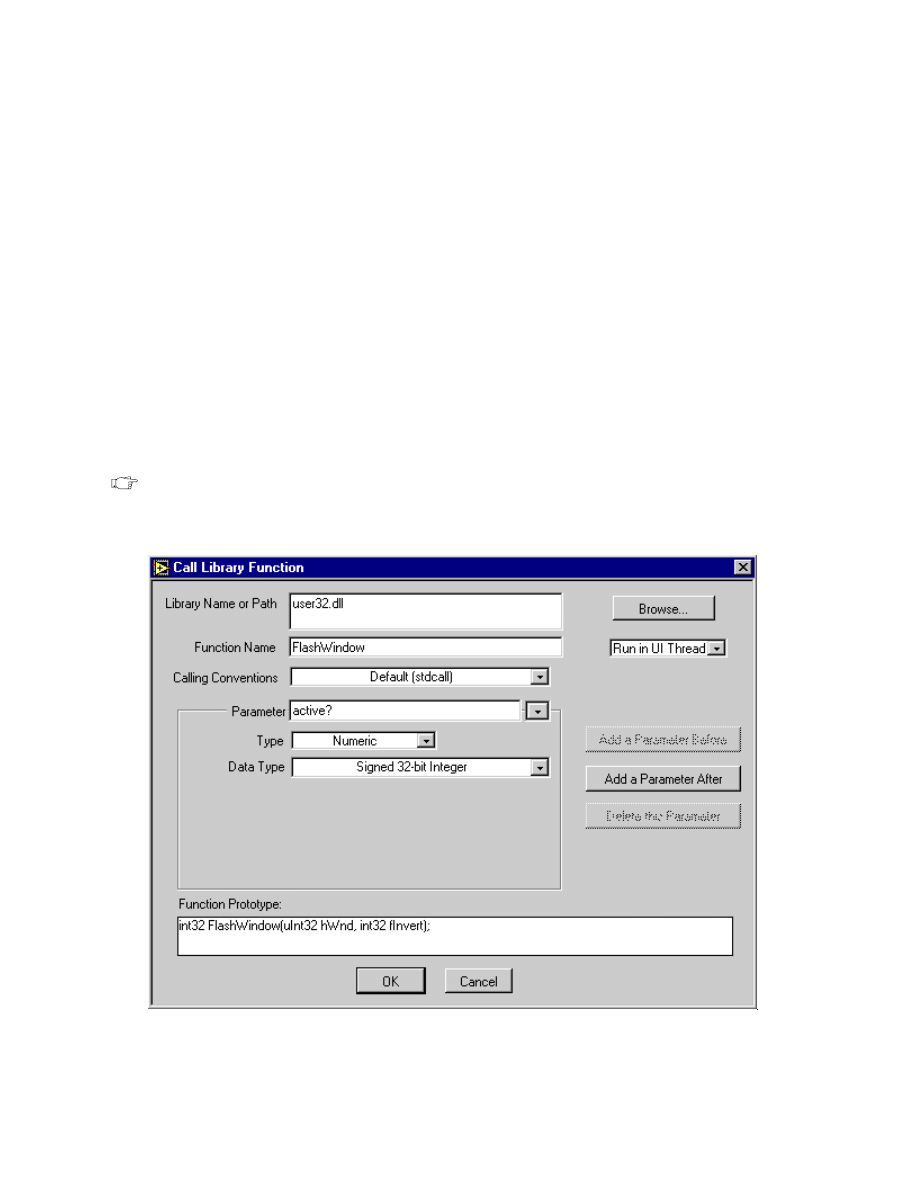
Module 3 Lesson 5 Exercises
©
National Instruments Corporation
3-5-11
LabVIEW Advanced I Course Manual
Return Type
The return type for the function is defined as a 32-bit signed integer:
int
32 bit signed integer
The Win32 API defines BOOL to be a 32-bit signed integer.
Parameters
The Microsoft Win32 Programmer’s Reference lists the data types of each of
the parameters to the FlashWindow function; the actual type definitions are
all found in the
winuser.h
file.
HWND hWnd—Identifies the window to be flashed. This is the window
refnum generated by Get Window RefNum.vi.
BOOL bInvert—BOOL is a 32-bit signed integer.
Note
FlashWindow uses the default (_stdcall) calling convention.
Configure the Call Library Function as shown below:
3. After you have finished building the diagram, save the VI. Specify a
Window Name on the front panel window name control, flash time, and

Module 3 Lesson 5 Exercises
LabVIEW Advanced I Course Manual
3-5-12
©
National Instruments Corporation
number of flashes. Run the VI and observe that the named window’s title
bar flashes the specified number of times. For example, specify the
Window Name to be Flash Title Bar.vi Diagram, run the VI, and you
will see the Diagram window’s title bar flash.
4. Enter different values and window names and run the VI several times.
After you are done, close the VI.
End of Exercise 5-2

Module 3 Lesson 5 Exercises
©
National Instruments Corporation
3-5-13
LabVIEW Advanced I Course Manual
Additional Exercise
5-3
Create a LabVIEW VI that uses the SetWindowTextA windows
API function in
user32.dll
to rename a window. The user will
specify the window name on the front panel of your VI. Use Get
Window Refnum.vi, which is provided to you to obtain the
windows refnum from the window name. The VI front panel is
already built for you as Rename.vi. Finish building the block
diagram. Use the following prototype for the SetWindowTextA
function for the LabVIEW Call Library Function:
int32 SetWindowTextA(uInt32 hWnd, CStr windowName);

Module 3 Lesson 5 Exercises
LabVIEW Advanced I Course Manual
3-5-14
©
National Instruments Corporation
Notes
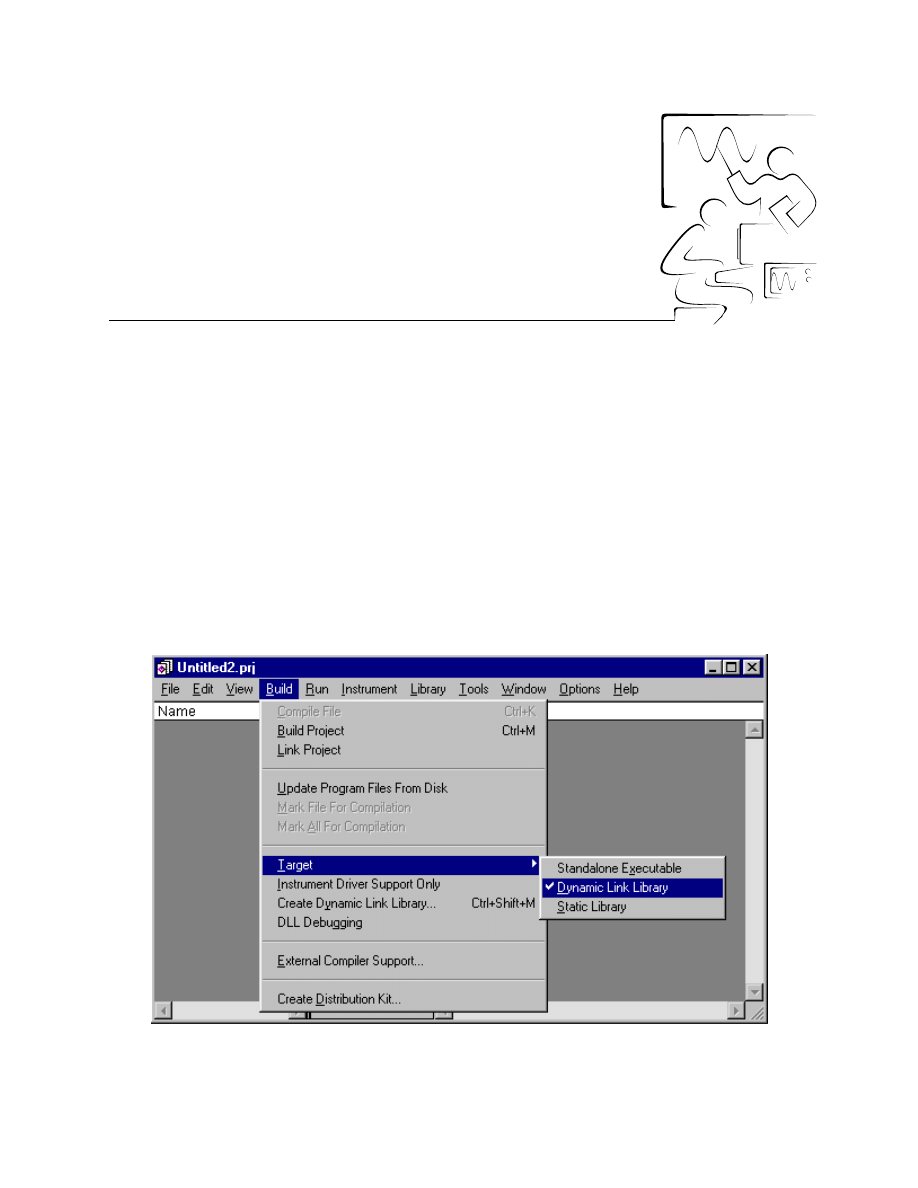
©
National Instruments Corporation
3-6-1
LabVIEW Advanced I Course Manual
Module 3
Lesson 6
Exercises
Exercise 6-1
Objective:
To create a simple DLL using the LabWindows/CVI compiler.
You will write and compile a simple DLL using the LabWindows/CVI
compiler. You then will call the DLL using the LabVIEW Call Library
Function.
1. Double-click on the LabWindows/CVI icon in the LabWindows/CVI
program group to launch the LabWindows/CVI development
environment.
2. Create a new project. Select Target: Dynamic Link Library from the
Build menu.

Module 3 Lesson 6 Exercises
LabVIEW Advanced I Course Manual
3-6-2
©
National Instruments Corporation
3. Create a new source file by selecting New » Source(*.c) file from the
File menu. Type in the following source code.
#include <cvirte.h>
#include <userint.h>
int __stdcall DllMain (HINSTANCE hinstDLL, DWORD
fdwReason, LPVOID lpvReserved)
{
if (fdwReason == DLL_PROCESS_ATTACH) {
MessagePopup("In DllMain", "I've been loaded");
}
else if (fdwReason == DLL_PROCESS_DETACH) {
MessagePopup("In DllMain", "I've been unloaded");
}
return 1;
}
void fnInternal(void)
{
MessagePopup("", "In internal DLL function");
}
void fnDLLTest(void)
{
MessagePopup("In DLL Test Function", "Hi there");
fnInternal();
}
Notice that
DllMain
has the
_stdcall
keyword before it. This defines
the calling convention for the function. In Windows 95/NT/98, there are
two calling conventions, the C calling convention, denoted by
_cdecl
,
and the standard call convention, denoted by
_stdcall
.
4. Save this file in the
LV_AdvI\cvi
directory as
firstdll.c
and add it
to the project by selecting Add File to Project from the File menu.
5. Create a new header file by selecting New » Include(*.h) from the File
menu and type the following:
void fnDLLTest(void);
Save this file as
firstdll.h
and add this to the project as well.
6. Go to the project window and save the project as
firstdll.prj
. Then,
select Create Dynamic Link Library from the Build menu. Select OK
if you are prompted to set debugging to none in order to create the DLL.
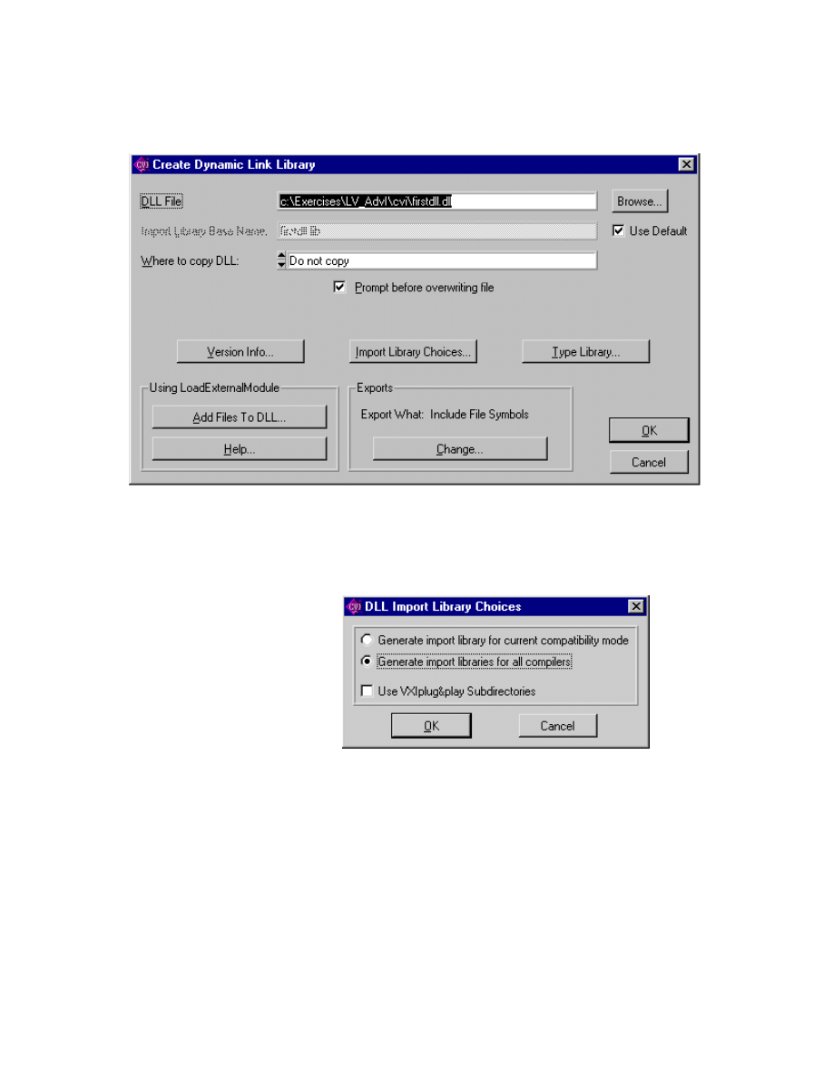
Module 3 Lesson 6 Exercises
©
National Instruments Corporation
3-6-3
LabVIEW Advanced I Course Manual
7. The following Create Dynamic Link Library dialog box will appear
(your file path will be different).
8. Click on the Import Library Choices... button. On the next dialog box,
select Generate Import Libraries for All Compilers and click on OK.
Selecting this option will create import libraries for each of the four
supported compilers in subdirectories under the project’s root.
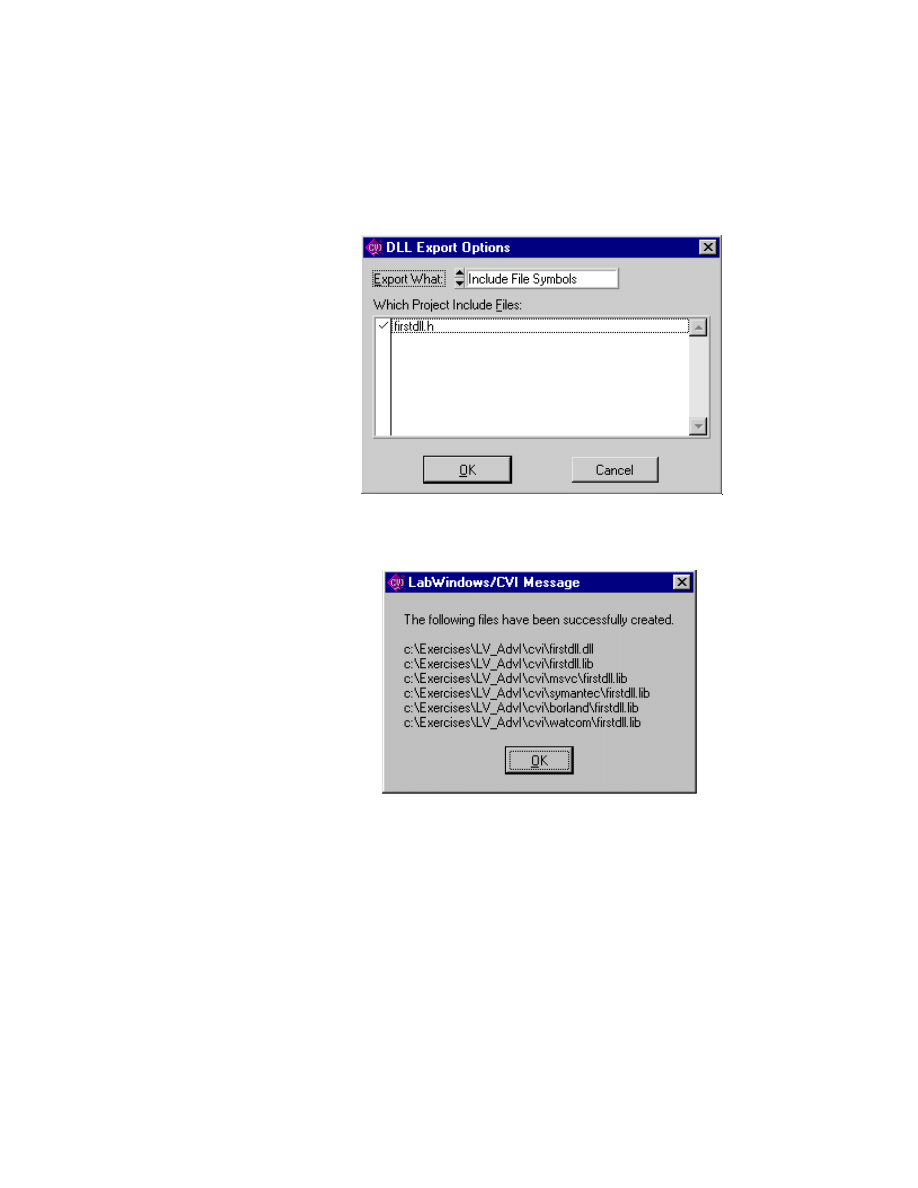
Module 3 Lesson 6 Exercises
LabVIEW Advanced I Course Manual
3-6-4
©
National Instruments Corporation
9. Click on the Change... button in the Exports section. In the DLL Export
Options dialog, check firstdll.h and then click on OK.
LabWindows/CVI will use this header file to determine what functions
to export. The only function prototype in the header file is for
fnDLLTest
and thus will be the only function exported.
10. Finally, click OK to have LabWindows/CVI create the DLL and import
libraries (your file paths will be different).
By default, the names of the DLL and import libraries created are the
same base name as the project. In this case,
firstdll.dll
is created,
along with five copies of
firstdll.lib
(import library). One import
library always is created in the same directory as the DLL. That import
library is created with the current compatibility mode, Visual C++.
Another copy of that import library is placed in the
msvc
subdirectory.
The three remaining import libraries are for the other three compilers
and stored in their respective subdirectories (Borland, Symantec,
Watcom).
If you want to distribute this DLL and you know which compiler your
DLL will be used with, then you just need to ship the DLL, the header
file, and the import library for that particular compiler. If you do not
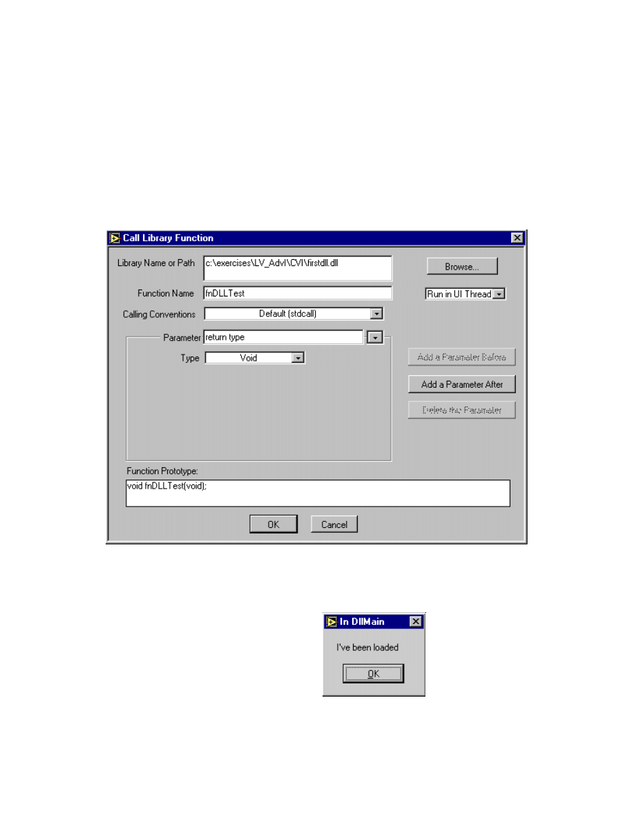
Module 3 Lesson 6 Exercises
©
National Instruments Corporation
3-6-5
LabVIEW Advanced I Course Manual
know which compiler your DLL will be used with (which is the case
most of the time), you can distribute all of the import libraries with the
DLL and header file. The end users must decide which import library to
use based on their compiler. For LabVIEW, you will need the DLL and
the header file to help configure the Call Library Function Node.
11. Close all open windows and exit CVI.
12. Launch LabVIEW and open a new VI. In the diagram window, access
the Call Library Function node from the Functions » Advanced palette.
Configure the Call Library Function as shown below:
13. Click on the OK button. You will see the first message pop-up indicating
that the DLL is loaded, as shown below. You will see that the VI run
arrow is broken until you press OK on this message box.
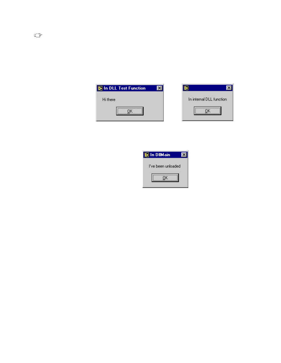
Module 3 Lesson 6 Exercises
LabVIEW Advanced I Course Manual
3-6-6
©
National Instruments Corporation
Note
When you first run this VI, the message pop-up appears behind the VI
window, and you may not be able to see it. Press <Alt-Tab> to bring up the
dialog box and click OK.
14. Run the VI. You should see a message pop-up when the fnDLLTest
function is called and another message pop-up for the internal call from
fnDLLTest to fnInternal, as shown below:
15. After you finish running the VI, save the VI as Firstdll.vi and then close
it. When the VI is closed, the DLL is unloaded and you will see the
unloaded message pop-up as shown below.
End of Exercise 6-1

Module 3 Lesson 6 Exercises
©
National Instruments Corporation
3-6-7
LabVIEW Advanced I Course Manual
Exercise 6-2A
Objective:
To create a simple DLL using the Visual C++ compiler
(Compiling of the DLL is a demo only on the instructor’s machine.)
You will observe writing and compiling a simple DLL using the
Visual C++ compiler on your instructor’s machine. Then you will call the
DLL using LabVIEW’s Call Library Function. This DLL is in the
exercises\LV_AdvI
directory.
1. From the Start menu, choose Programs » Microsoft Visual C++ 5.0 »
Microsoft Visual C++ 5.0. This launches Microsoft Visual C++ 5.0.
2. Create a new project by selecting New » Projects from the File menu.
A window will appear with the possible types of new files. Select
Projects tab and choose WIN32 Dynamic Link Library as the Type.
Name the project
ourdll
. Specify the path as
c:\exercises\LV_AdvI
.
3. Use a text editor or the editor built into Microsoft Visual C++ to create
the C source code and header files. Name the files
ourDLL.c
and
ourDLL.h
. The listings for the two files are shown below:
/* ourDLL.c source code */
#include <windows.h>
#include <string.h>
#include <ctype.h>
#include "ourdll.h"
BOOL WINAPI DllMain (HINSTANCE hModule, DWORD dwFunction,
LPVOID lpNot)
{
return TRUE;
}
/* Add two integers */
_declspec (dllexport) long add_num(long a, long b){
return((long)(a+b));}
/* This function finds the average of an array of single
precision numbers */
_declspec (dllexport) long avg_num(float *a, long size,
float *avg)
{
int i;
float sum=0.0f;
if(a != NULL)
{
for(i=0;i < size; i++)
sum = sum + a[i];
}
else
return (1);

Module 3 Lesson 6 Exercises
LabVIEW Advanced I Course Manual
3-6-8
©
National Instruments Corporation
*avg = sum / size;
return (0);
}
/* Counts the number of integer numbers appearing in a
string. */
_declspec (dllexport) unsigned int numIntegers (unsigned
char * inputString)
{
/* Note that this function does not check for sign,
decimal, or exponent */
int lastDigit = 0;
unsigned int numberOfNumbers = 0, stringSize, i;
stringSize = strlen(inputString);
for(i = 0; i < stringSize; i++)
{
if ( !lastDigit && isdigit(inputString[i]))
numberOfNumbers++;
lastDigit = isdigit(inputString[i]);
}
return numberOfNumbers;
}
Header file listing:
/*
* ourDLL.h: header file
*/
BOOL WINAPI DllMain(HINSTANCE hinstDLL,DWORD,LPVOID);
_declspec (dllexport) long add_num(long, long);
_declspec (dllexport) long avg_num(float *, long, float *);
_declspec (dllexport) unsigned int numIntegers
(unsigned char *);

Module 3 Lesson 6 Exercises
©
National Instruments Corporation
3-6-9
LabVIEW Advanced I Course Manual
Note
If source code is saved with the default .cpp extension, the function names will
be mangled (decorated) unless declared with extern “c”. If you used the
_stdcall calling convention, the module definition file would be required, as
shown below:
/* ourDLL.def */
EXPORTS
avg_num
add_num
numIntegers
4. The example DLL above defines three simple functions:
•
add_num
adds two integers.
•
avg_nu
m finds the simple average of an array of numeric data.
•
numIntegers
counts the number of integers in a string.
The above functions use the C calling conventions.
Note
LabVIEW can call DLLs that use the stdcall calling convention, as well as
DLLs that use C calling conventions.
5. Add
ourDLL.c
to your project by selecting the Add to Project option
from the Project menu. After adding these files to the project, press the
OK button in the dialog box.
6. To compile the code into a DLL, select Build ourDLL.DLL from the
Build menu. After
ourDLL.dll
is built successfully, you can use the
LabVIEW Call Library Function to call the different functions in the
DLL.
7. Now, you will create a VI that calls the
avg_num
function in
ourDLL.dll
. Then, open a new VI in LabVIEW. On the block
diagram, place the Call Library Function icon from the Advanced
subpalette of the Functions palette. Pop up on the icon and select the
Configure... option.
8. Configure the node to call the
avg_num
function in
ourDLL.dll
as
shown in the figure below. You first specify the location of the DLL by
typing in the pathname. Also, specify the name of the function you want
to call in the DLL. In this case, it is
avg_num
. The calling convention
for this function in the DLL is C. The return type is signed 32-bit Integer.
The parameters to the function are an Array Data Pointer to 4-byte
single-precision floating point numbers, a 32-bit signed integer that
contains the size of the array, and a pointer to a 4-byte single-precision
floating-point value, which will return the average of the elements in the
array.
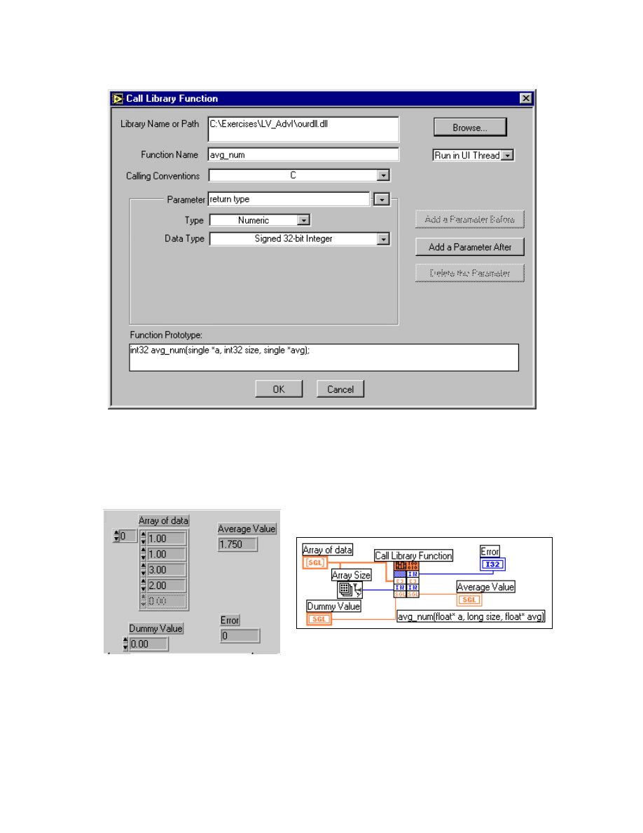
Module 3 Lesson 6 Exercises
LabVIEW Advanced I Course Manual
3-6-10
©
National Instruments Corporation
9. Create the front panel and block diagram as shown below. Then, connect
the appropriate controls and indicators to the Call Library Function icon.
After you are done, save the VI as ARRAYAVG.vi in
dllclass.llb
.
Front Panel and Block Diagram

Module 3 Lesson 6 Exercises
©
National Instruments Corporation
3-6-11
LabVIEW Advanced I Course Manual
10. Enter values in the array of data and run the VI. You will see that the
avg_num
function in the DLL will calculate the average and return the
value to LabVIEW.
11. As a further exercise on your own, build a VI that calls the
numIntegers
function in
ourDLL.dll
. Save the VI as Number of
Integers.vi in
dllclass.llb
.
End of Exercise 6-2A

Module 3 Lesson 6 Exercises
LabVIEW Advanced I Course Manual
3-6-12
©
National Instruments Corporation
Exercise 6-2B
(Compiling the DLL Using the LabWindows/CVI Compiler)
Objective:
To create a simple DLL using the CVI compiler.
You will observe writing and compiling a simple DLL using the CVI
compiler. Then you will call the DLL using the LabVIEW Call Library
Function. This DLL is in the LabVIEW directory.
1. Launch LabWindows CVI by choosing Programs »
CVI(Common) » CVI.
2. From the File menu, choose New » Project(*.prj) and then save the
project as
ourDLL
.
3. From the File menu, choose New » Source(*.c). Type the following
source code and save the file as
ourDLL.c
. Choose New » Include(*.h)
and then type in the function prototypes. Save the file as
ourDLL.h
.
/* ourDLL.c source code */
#include <windows.h>
#include <string.h>
#include <ctype.h>
#include <cvirte.h> /* Needed if linking in external
compiler; harmless otherwise */
#include "ourdll.h"
BOOL WINAPI DllMain (HINSTANCE hModule,DWORD dwFunction,
LPVOID lpNot)
{
return TRUE;
}
/*Add two integers */
long _export add_num(long a, long b)
{
return((long)(a+b));
}
/* This function finds the average of an array of single
precision numbers*/
long _export avg_num(float *a, long size, float *avg)
{
int i;
float sum=0.00;
if(a != NULL)
{
for(i=0;i < size; i++)
sum = sum + a[i];
}
else
return (1);
*avg = sum / size;
return (0);
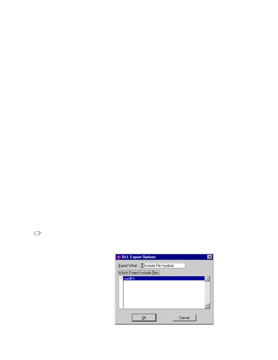
Module 3 Lesson 6 Exercises
©
National Instruments Corporation
3-6-13
LabVIEW Advanced I Course Manual
}
/* Counts the number of integer numbers appearing in a string. */
unsigned int _export numIntegers (unsigned char *
inputString)
{
/* Note that this function does not check for sign, decimal,
or exponent */
int lastDigit = 0;
unsigned int numberOfNumbers = 0, stringSize, i;
stringSize = strlen(inputString);
for(i = 0; i < stringSize; i++)
{
if ( !lastDigit && isdigit(inputString[i]))
numberOfNumbers++;
lastDigit = isdigit(inputString[i]);
}
return numberOfNumbers;
}
Header file listing:
/*
* ourDLL.h: header file
*/
long _export add_num(long, long);
long _export avg_num(float *, long, float *);
unsigned int _export numIntegers (unsigned char *);
4. The example DLL above defines three simple functions:
•
add_num
adds two integers
•
avg_num
finds the simple average of an array of numeric data
•
numIntegers
counts the number of integers in a string
The above functions use the C calling conventions.
Note
LabVIEW can call DLLs that use the stdcall calling convention, as well as
DLLs that use C calling conventions.
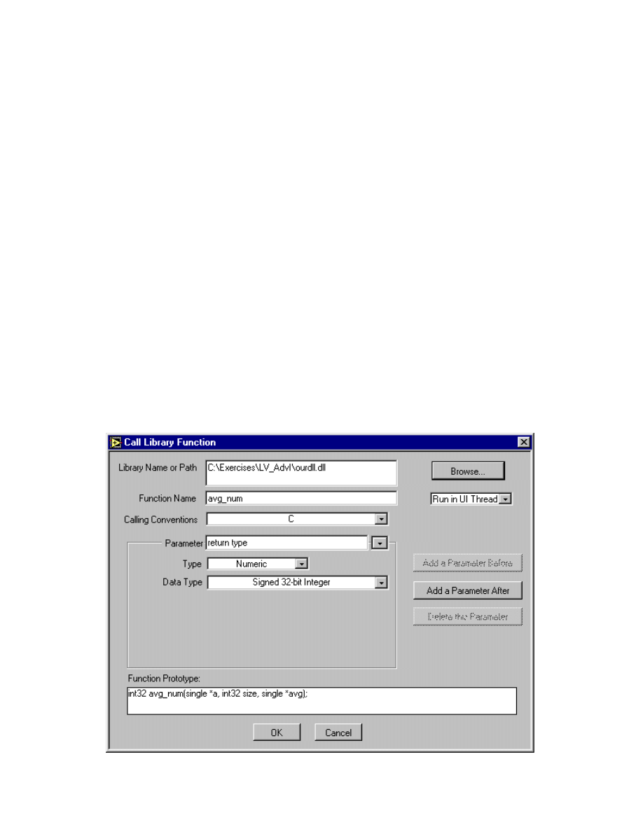
Module 3 Lesson 6 Exercises
LabVIEW Advanced I Course Manual
3-6-14
©
National Instruments Corporation
5. Add the
ourDLL.c
file and
ourDLL.h
file to your project by choosing
Add Files into Project... from the Edit menu. Select Target: Dynamic
Link Library from the Build menu. Next, build the DLL by selecting
Create Dynamic Link Library from the Build menu. Be sure you
export the DLL functions by selecting the header file from the DLL
Export options as shown below.
6. After
ourDLL.dll
is built successfully, you can use the LabVIEW Call
Library Function to call the different functions in the DLL.
7. Now you will create a VI that calls the
avg_num
function in
ourDLL.dll
. Place the Call Library Function icon from the Advanced
subpalette of the Functions palette. Pop up on the icon and select the
Configure... option.
8. Configure the node to call the
avg_num
function in
ourDLL.dll
as
shown in the figure below. You first will specify the location of the DLL
by typing in the pathname. Also, specify the name of the function you
want to call in the DLL. In this case, it is
avg_num
. The calling
convention for this function in the DLL is C.
The return type is signed 32-bit integer. The parameters to the function
are an Array Data Pointer to 4-byte single-precision floating-point
numbers, a 32-bit signed integer that contains the size of the array, and
a pointer to a 4-byte single-precision floating-point value, which will
return the average of the elements in the array.
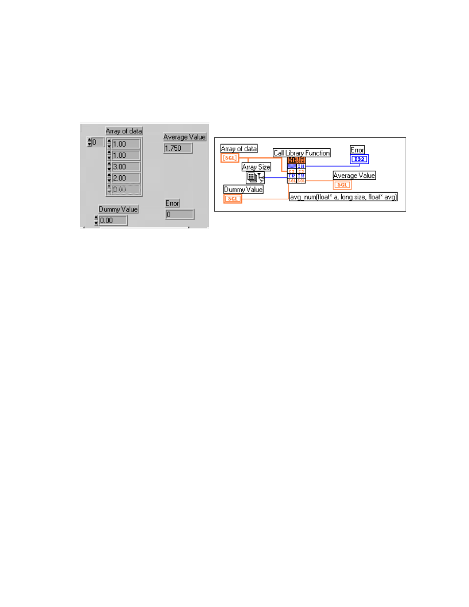
Module 3 Lesson 6 Exercises
©
National Instruments Corporation
3-6-15
LabVIEW Advanced I Course Manual
9. Create the front panel and block diagram as shown below. Then, connect
the appropriate controls and indicators to the Call Library Function icon.
After you are done, save the VI as ARRAYAVG.vi in
dllclass.llb
.
Front Panel and Block Diagram
10. Enter values in the array of data and run the VI. You will see that the
avg_num
function in the DLL will calculate the average and return the
value to LabVIEW.
11. As a further exercise on your own, build a VI that calls the
numIntegers
function in
ourDLL.dll
. Save the VI as Number of
Integers.vi in
dllclass.llb
.
End of Exercise 6-2B

Module 3 Lesson 6 Exercises
LabVIEW Advanced I Course Manual
3-6-16
©
National Instruments Corporation
Exercise 6-3A
Objective:
To create a 32-bit DLL with two exported functions that demonstrate how to resize
your array and call them from LabVIEW.
(Compiling of the DLL is demo-only on instructor’s machine.)
You will write functions in a DLL that will require you to resize an array in
LabVIEW. This will illustrate how to allocate array data in LabVIEW and
pass it to the DLL to act as a buffer. You will use the Visual C++ compiler
to compile this DLL.
1. From the Start menu, choose Programs » Microsoft Visual C++ 5.0 »
Microsoft Visual C++ 5.0. This launches Microsoft Visual C++ 5.0.
2. Create a new project by selecting New from the File menu. A window
will appear with the possible types of new files. Select the Projects tab
and choose WIN32 Dynamic Link Library as the Type. Name the project
acquire
. Specify the path as
c:\exercises\LV_AdvI
.
3. Use a text editor or the editor built into Microsoft Visual C++ to create
the C source code. If you use the Visual C++ editor to create source file,
select the Add to Project option. Save the file as
acquire.c
.
/*
* acquire.c: Dll source file for EX 6-3A
* functions: determineSize
* acquireData
*/
#include <windows.h>
#include <stdlib.h>
/* function prototypes*/
BOOL WINAPI DllMain(HINSTANCE hinstDLL,DWORD,LPVOID);
_declspec (dllexport) int determineSize(int, int);
_declspec (dllexport) void acquireData(float *, int, int);
BOOL WINAPI DllMain (HINSTANCE hModule, DWORD dwFunction,
LPVOID lpNot)
{
return TRUE;
}
/* determineSize function determines the size of the array
data */
_declspec (dllexport) int determineSize(int channels, int
numScans)
{
return(channels * numScans);
}
/* acquireData acquires the data and puts it into the
array*/
_declspec (dllexport) void acquireData(float* buffer, int
channels, int numScans)
{
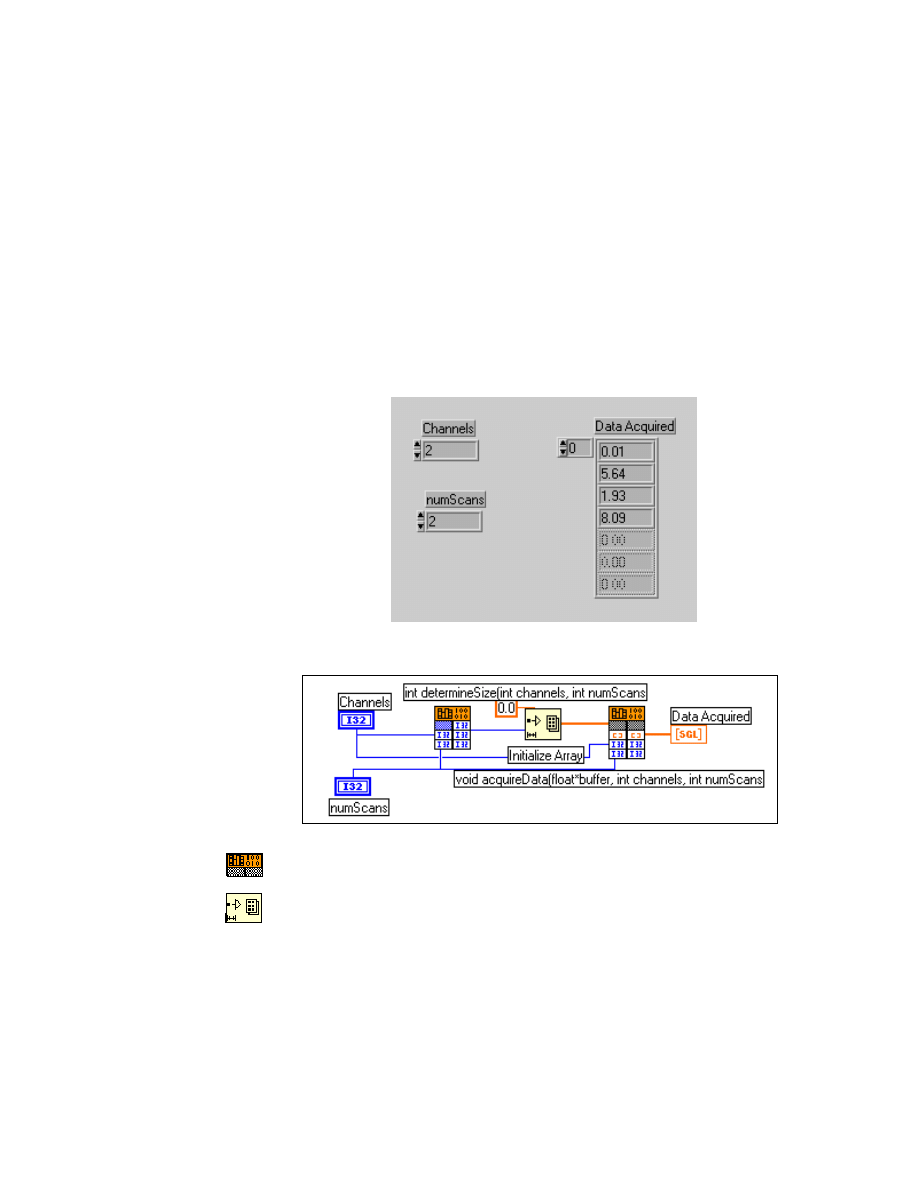
Module 3 Lesson 6 Exercises
©
National Instruments Corporation
3-6-17
LabVIEW Advanced I Course Manual
int i;
for(i=0; i < channels * numScans; i++)
buffer[i] = (float) rand()/3276.7f;
}
4. If the
.c
file is not already added to your project, choose the Add to
Project... option from the Project menu. Select the file
acquire.c
.
Build the DLL by selecting Build acquire.dll from the Build menu.
5. You will call the
determineSize
and
acquireData
functions from
LabVIEW. Open a new VI in LabVIEW and create the front panel and
block diagram as shown below:
Front Panel and Block Diagram
Call Library function (Functions » Advanced palette).
Initialize Array function (Functions » Array palette).
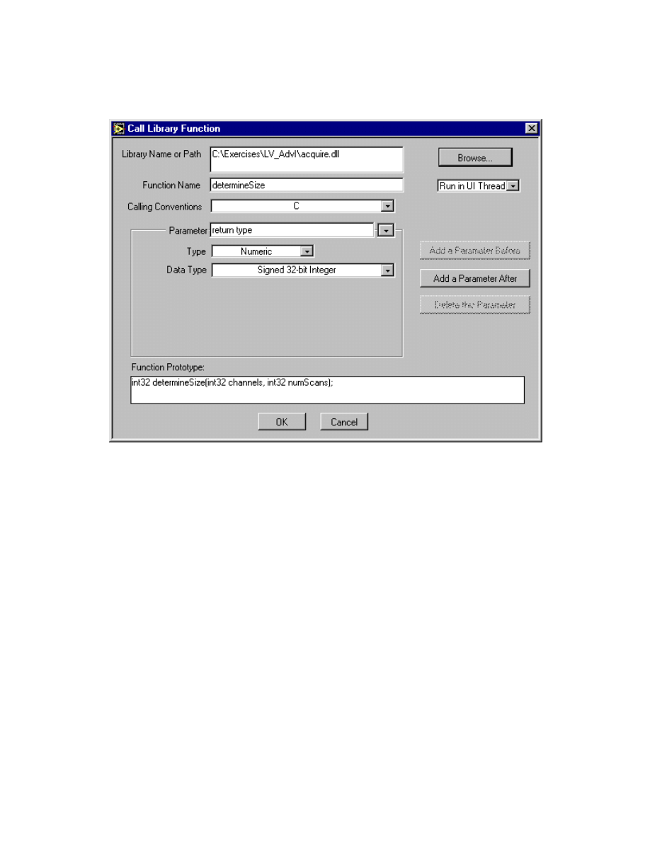
Module 3 Lesson 6 Exercises
LabVIEW Advanced I Course Manual
3-6-18
©
National Instruments Corporation
Configure the two functions as shown below, making sure that you specify
the correct path to the DLL:
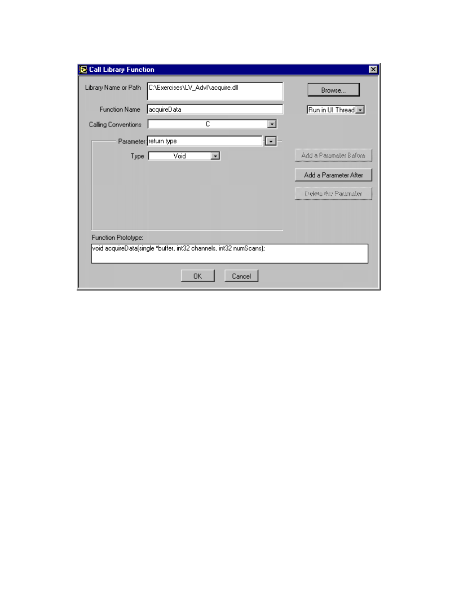
Module 3 Lesson 6 Exercises
©
National Instruments Corporation
3-6-19
LabVIEW Advanced I Course Manual
6. Save the VI as Acquire.vi in
dllclass.llb
. Enter different values for
channels and numScans and run the VI several times. After you finish,
close the VI.
End of Exercise 6-3A

Module 3 Lesson 6 Exercises
LabVIEW Advanced I Course Manual
3-6-20
©
National Instruments Corporation
Exercise 6-3B
Objective:
To create a 32-bit DLL with two exported functions that demonstrate how to resize
your array and then call them from LabVIEW.
You will write functions in a DLL that will require you to resize an array in
LabVIEW. This will illustrate how to allocate array data in LabVIEW and
pass it to the DLL to act as a buffer.
1. Launch LabWindows CVI by choosing Programs »
CVI(Common) » CVI.
2. From the File menu, choose New » Project(*.prj) and then save the
project as acquire.
3. From the File menu, choose New » Source(*.c). Type the following
source code and save the file as
acquire.c
. Choose New »
Include(*.h) and then type in the function prototypes. Save the file as
acquire.h
.
Header File
/* acquire.h: Dll header file */
/* function prototypes*/
#include <windows.h>
#include <stdlib.h>
BOOL WINAPI DllMain (HINSTANCE, DWORD, LPVOID);
int _export determineSize(int, int);
void _export acquireData(float *, int, int);
Source File
/*
* acquire.c: Dll source file for EX 6-3B
* functions: determineSize
* acquireData
*/
#include "acquire.h"
BOOL WINAPI DllMain (HINSTANCE hModule, DWORD dwFunction,
LPVOID lpNot)
{
return TRUE;
}
/* determineSize function determines the size of the array
data */
int _export determineSize(int channels, int numScans)
{
return(channels * numScans);
}
/* acquireData acquires the data and puts it into the array*/
void _export acquireData(float* buffer, int channels, int
numScans)
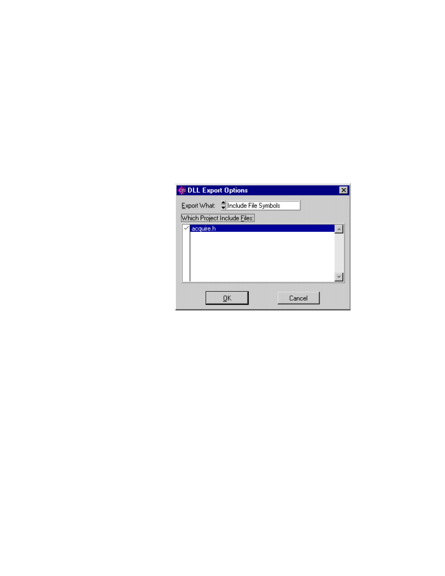
Module 3 Lesson 6 Exercises
©
National Instruments Corporation
3-6-21
LabVIEW Advanced I Course Manual
{
int i;
for(i=0; i < channels * numScans; i++)
buffer[i] = (float) rand()/3276.7f;
}
4. Add the
acquire.c
file and
acquire.h
file to your project by
choosing Add Files into Project... from the Edit menu. In the Project
Window, select
acquire.c
and
acquire.h
. Select Target: Dynamic
Link Library from the Build menu. Next, build the DLL by selecting
Create Dynamic Link Library from the Build menu. Be sure you
export the DLL function by selecting the header file from the DLL
Export options as shown below:
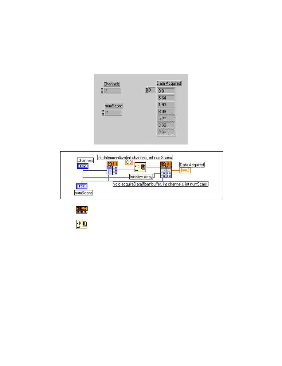
Module 3 Lesson 6 Exercises
LabVIEW Advanced I Course Manual
3-6-22
©
National Instruments Corporation
5. You will call the
determineSize
and
acquireData
functions from
LabVIEW. Open a new VI in LabVIEW and create the front panel and
block diagram as shown below:
Front Panel and Block Diagram
Call Library function (Functions » Advanced palette).
Initialize Array function (Functions » Array palette).
Configure the two functions as shown below, making sure that you
specify the correct path to the DLL:
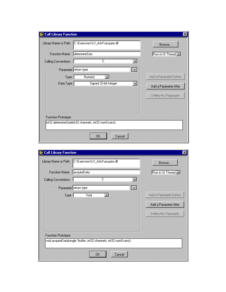
Module 3 Lesson 6 Exercises
©
National Instruments Corporation
3-6-23
LabVIEW Advanced I Course Manual

Module 3 Lesson 6 Exercises
LabVIEW Advanced I Course Manual
3-6-24
©
National Instruments Corporation
6. Save the VI as Acquire.vi in
dllclass.llb
. Enter different values for
channels and numScans and run the VI several times. After you have
finished, close the VI.
End of Exercise 6-3B

Module 3 Lesson 6 Exercises
©
National Instruments Corporation
3-6-25
LabVIEW Advanced I Course Manual
Exercise 6-4
Objective:
To create a 32-bit DLL with one exported function containing a CIN function to resize
an array using the Visual C++ compiler.
(Compiling of the DLL is a demo only on the instructor’s machine.)
You will write a function in a DLL that will use a CIN function to resize the
array.
1. Create a new project by selecting New from the File menu. Choose the
type to be a Win32 Dynamic Link Library and name the project resize.
Create the
.c
file by choosing New File from the File menu. Write the
following source code and name the file
resize.c
. Notice that the
header file
extcode.h
is included and the
DSSetHandleSize
function is used to resize the array.
/*
* resize.c: Dll source file for EX 6-4
* functions: acquireData
*/
#include <windows.h>
#include <stdlib.h>
#include "C:\Program Files\National Instruments\labview\cintools\extcode.h"
typedef struct {
int32 dimSize;
float32 arg1[1];
} TD1;
typedef TD1 **TD1Hdl;
/* function prototypes*/
BOOL WINAPI DllMain(HINSTANCE hinstDLL,DWORD,LPVOID);
_declspec (dllexport) int32 acquireData(TD1Hdl, int32,
int32);
BOOL WINAPI DllMain (HINSTANCE hModule, DWORD
dwFunction, LPVOID lpNot)
{
return TRUE;
}
/* acquireData acquires the data and puts it into the
LabVIEW array*/
_declspec (dllexport) int32 acquireData(TD1Hdl LVHandle,
int32 channels, int32 numScans)
{
int32 sizeofarray, i;
MgErr error;
/*determine size of buffer*/
sizeofarray = channels * numScans;
/* allocate memory for LVHandle*/
error=DSSetHandleSize(LVHandle, (sizeofarray+1) *
sizeof(float32));
if(error!=mFullErr && error!=mZoneErr)
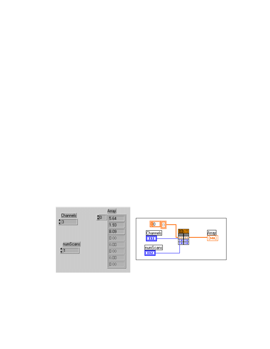
Module 3 Lesson 6 Exercises
LabVIEW Advanced I Course Manual
3-6-26
©
National Instruments Corporation
{
/* initialize four byte header to size of array */
(*LVHandle)->dimSize = sizeofarray;
/* acquire data */
for(i=0; i < sizeofarray; i++)
(*LVHandle)->arg1[i] = (float32) rand()/
3276.7f;
return 0;
}
else
return 1;
}
2. Add
resize.c
to the resize project by selecting Add To Project...
from the Project menu and selecting resize.c.
3. Add the library that contains the LabVIEW CIN functions to your
project by choosing Add To Project... from the Project menu and
choosing
labview.lib
from the
LabVIEW/cintools/win32
directory
.
4. Select Project » Settings » C/C++ tab. Choose Category to be Code
Generation and Use run-time library as multithreaded DLL.
5. Build the DLL by selecting Build Resize.dll from the Build menu.
6. Now you will build a VI and use the Call Library function to call the
acquireData
function. Build the front panel and block diagram of the
VI as shown below and save the VI as Resize.vi.
Front Panel and Block Diagram
7. Configure the Call Library function as shown below. Be sure to specify
the correct path to
resize.dll
.
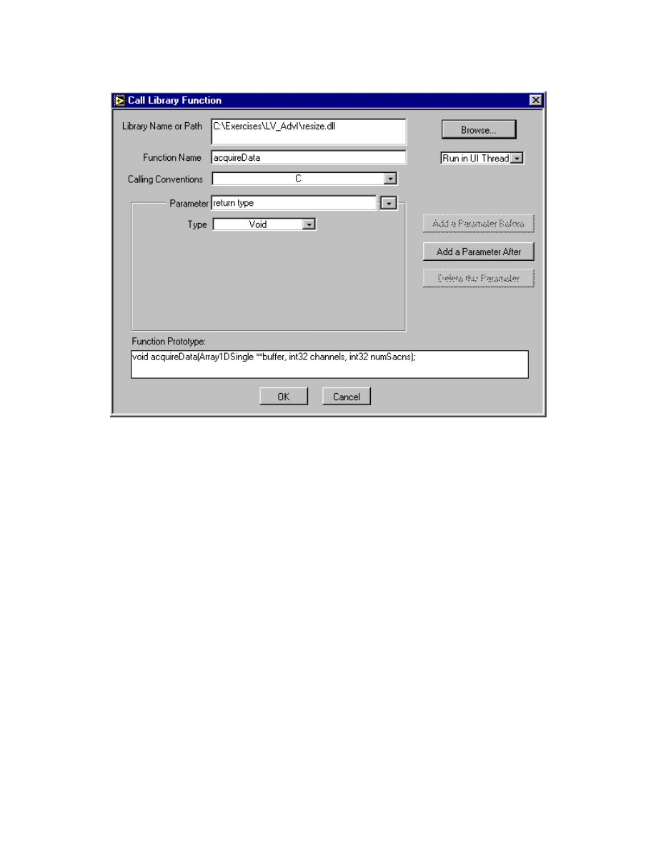
Module 3 Lesson 6 Exercises
©
National Instruments Corporation
3-6-27
LabVIEW Advanced I Course Manual
8. Specify values for number of channels and number of scans and then run
the VI. The correct array buffer is allocated within the DLL and an array
of data is returned to LabVIEW. After you have finished, close the VI.
End of Exercise 6-4

Module 3 Lesson 6 Exercises
LabVIEW Advanced I Course Manual
3-6-28
©
National Instruments Corporation
Additional Exercise
6-5
Write a DLL that receives two strings from LabVIEW, string1 and
string2, and concatenates them. Return the concatenated string as a
LabVIEW string handle. Be sure that you resize your string within
the DLL. Then, write a VI that will call your
Concatenate
function. Name the C file
Concat.c
and the LabVIEW VI
Concat.vi.
Hint: Use the following function prototype for your function:
void Concatenate(CStr* string1, CStr*
string2, LStrHandle LVHandle, int32 size);
Note
Remember to include labview.lib from the cintools directory if you are using
the Visual C++ compiler. Also, select the Project » Settings » C/C++ tab and
choose Run-time library as multithreaded DLL.

©
National Instruments Corporation
A-1
LabVIEW Advanced I Course Manual
Appendix
This appendix contains the following sections of useful information:
A. Application Notes
B. The LabVIEW Style Guide
C. Remote Automation using DCOM
D. Dynamic Data Exchange
E. Networked DDE (NetDDE)
F. LabVIEW Internet Toolkit
G. Common Questions about Writing and Calling DLLs
H. Common Questions about CINs
I.
Instructor’s Notes
Appendix
LabVIEW Advanced I Course Manual
A-2
©
National Instruments Corporation
A. Application Notes
Many LabVIEW application notes are available. You can request these
notes from National Instruments or access them from the National
Instruments ftp site, web site, or FaxBACK system. The Instrupedia
CD-ROM also contains all application and technical notes available.
Although some application notes may pertain to LabVIEW for Macintosh,
they also apply to LabVIEW for Windows. A list of application notes is
given below. However, we are constantly adding new application notes. For
a current list, contact National Instruments.
Part Number
Title
341185A-01
Building Internet-Enabled Virtual Instruments with LabVIEW,
LabWindows/CVI, and ComponentWorks
341095C-01
Creating Reusable Test Code for LabVIEW, Visual Basic, and C/C++
with LabWindows/CVI
341234A-01
Designing Filters Using the Digital Filter Design Toolkit
340018D-01
Developing a LabVIEW Instrument Driver
340479-01
Fast Fourier Transforms and Power Spectra in LabVIEW
341210A-01
G Math - A New Paradigm for Mathematics
341143A-01
How to Call Win32 Dynamic Link Libraries (DLLs) from LabVIEW
340873B-01
How to Call Windows 3.X 16-Bit Dynamic Link Libraries (DLLs)
from LabVIEW
341455A-01
Jump-Starting Instrument Control with Interactive Control and
LabVIEW Instrument Wizard
341294B-01
LabVIEW 4.1 DAQ Wizards Automate Program Generation
341240A-01
LabVIEW and LabWindows/CVI Test Executives—Strategic
Overview
341423A-01
LabVIEW Instrument Driver Standards
341412C-01
LabVIEW Version 5.0, The Power to Make It Simple
341428A-01
LabVIEW Instrument Driver Checklist and Submittal Form
340478-01
Linear Systems in LabVIEW
341560A-01
Serial Polling and SRQ Servicing with NI-488.2 Software and
LabVIEW
340555-01
The Fundamentals of FFT-Based Signal Analysis and Measurement in
LabVIEW and LabWindows
340454-01
Timing a LabVIEW Operation

Appendix
©
National Instruments Corporation
A-3
LabVIEW Advanced I Course Manual
B. The LabVIEW Style Guide
LabVIEW with Style, by Gary W. Johnson and Meg Kay, contains many
examples of good LabVIEW programming. Based on input from actual
users and programmers, LabVIEW with Style discusses program design,
documentation, front panels, and diagrams. You can request this document
from National Instruments or access it from the National Instruments web
page.
341521A-01
Using IVI Drivers to Build Hardware-Independent Test Systems with
LabVIEW and LabWindows
341505A-01
Using IVI Drivers to Simulate Your Instrumentation Hardware in
LabVIEW and LabWindows
341419A-01
Using LabVIEW to Create Multithreaded Applications for Maximum
Performance and Reliability
341103A-01
Using Object Linking and Embedding (OLE) Automation in
LabVIEW 4.0
340455-01
Using Output Tunnels to Build Arrays
340930B-01
Using VXIplug&play Instrument Drivers with LabVIEW 4.0 for
Windows
341136A-01
Writing Win32 Dynamic Link Libraries (DLLs) and Calling Them
from LabVIEW
340987C-01
Writing Windows 3.X 16-Bit Dynamic Link Libraries (DLLs) and
Calling Them from LabVIEW
341029D-01
Your Competitive Advantage with LabVIEW
Part Number
Title

Appendix
LabVIEW Advanced I Course Manual
A-4
©
National Instruments Corporation
C. Remote Automation Using DCOM
This section discusses the various steps involved in getting LabVIEW to
work as a remote server. ActiveX clients can use DCOM to communicate
with a LabVIEW on a remote machine as a server.
DCOM is supported only on Windows 95/NT/98. You need to have one
server machine and one or more client machines running Windows
95/NT/98. LabVIEW 5.0 should be installed on the server machine. You
need to configure DCOM on both the server and the client machines.
Before you read further, there are two important issues to be mentioned:
•
You cannot communicate between two copies of LabVIEW on different
machines. The client LabVIEW will intercept all calls to the server.
•
You cannot do remote activation if the server is on a Windows 95/98
machine. LabVIEW has to be launched manually on the server machine.
The following sections discuss the different steps involved in performing
secure DCOM under both Windows 95/NT/98. Your client and server
machines must be hooked onto an NT domain to perform secure DCOM.
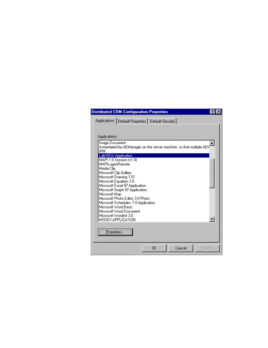
Appendix
©
National Instruments Corporation
A-5
LabVIEW Advanced I Course Manual
Configuring the Server on NT
1. Install LabVIEW and run it at least once.
You should be logged on as the System Administrator to configure
DCOM. The next few steps involve setting up access permissions for
clients to launch LabVIEW on the server machine.
LabVIEW must be run at least once on the server for the purpose of
registration with the system before performing the next steps.
2. Run the DCOM Configuration Utility (
DCOMCNFG.EXE
) from the
command line or from Start » Run. You should see the following
configuration dialog box.
3. DCOMCNFG lists the applications registered with the system.
LabVIEW Application should be listed; if not, you should run
LabVIEW.
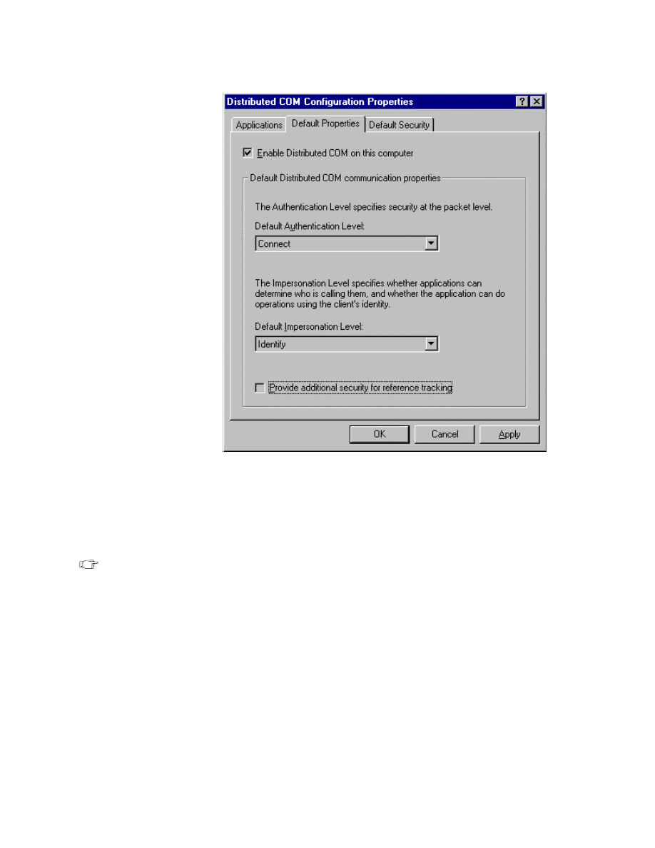
Appendix
LabVIEW Advanced I Course Manual
A-6
©
National Instruments Corporation
4. You should enable DCOM if not already enabled. To enable DCOM,
click on Default Properties tab. You can also set the default
authentication and impersonation levels here. It is advisable to set the
authentication to Connect and impersonation to Identify. If you need to
do nonsecure DCOM, you can set authentication to none.
Note
If you set authentication to none, call security for the entire machine is turned
off. Any client will be able to call into any COM server running on this
machine.
5. Click on Applications tab. Select LabVIEW Application and click on
Properties....
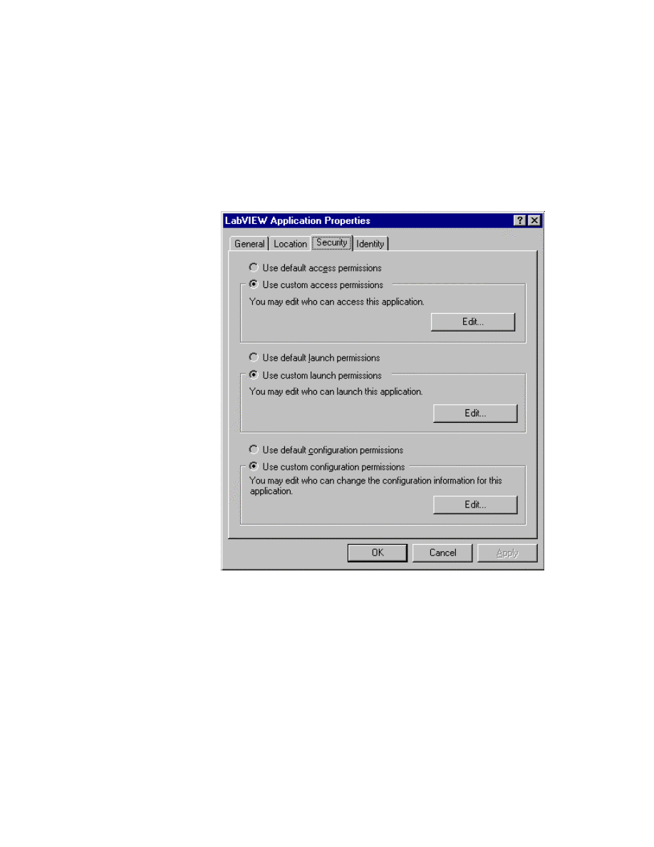
Appendix
©
National Instruments Corporation
A-7
LabVIEW Advanced I Course Manual
6. Select the Security tab. You can customize which users or groups of
users can launch, access, or configure an application, as shown below.
Choose the users/groups that are allowed access to LabVIEW server.
You need to specify the launch and access permissions. Always allow
access to SYSTEM—that is, the operating system. You can also choose
to use default permissions. If you do so, make sure you have provided
access permissions to the relevant users/groups in the Default Security
page of the DCOM Configuration Tool.
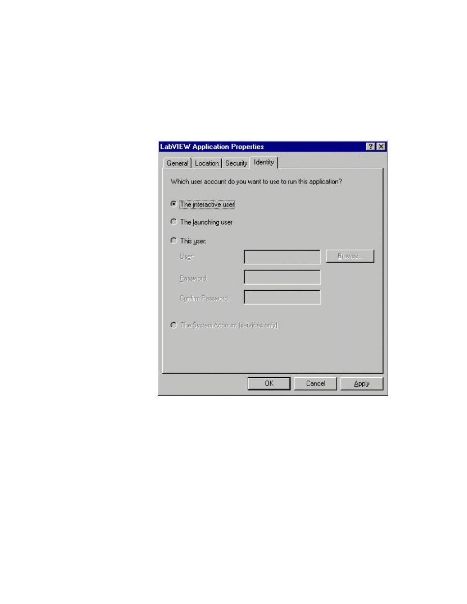
Appendix
LabVIEW Advanced I Course Manual
A-8
©
National Instruments Corporation
7. Select the Identity tab and choose the identity of the user on behalf of
whom LabVIEW is run on the server. Specify the interactive user if it
does not matter who is logged on the server. If you specify the launching
user or a particular user, make sure the user has proper access permission
for the server to function properly, or else you will get a “permission
denied” message from the server. If you have Windows 95 clients,
choose the interactive user.
8. Click OK and exit DCOMCNFG. LabVIEW is now configured for
remote automation.
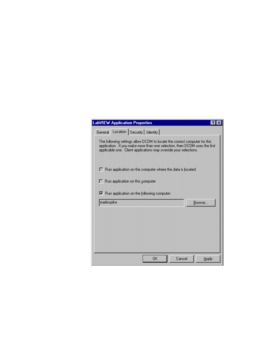
Appendix
©
National Instruments Corporation
A-9
LabVIEW Advanced I Course Manual
Configuring the Client on NT
1. You should be logged on as the System Administrator to configure
DCOM.
2. If LabVIEW has not been installed and run on the client machine, you
should run the attached registration file.
3. Run the DCOM Configuration Utility (
DCOMCNFG.EXE
) from the
command line or from Start » Run. This should bring up the DCOM
Configuration Tool.
4. Double-click on LabVIEW Application and click on the Location tab.
Uncheck Run application on this computer. Check Run application
on the following computer and specify the server machine name as
shown below:
5. Click OK to go to the Applications page. Click on the Default
Properties tab. Make sure the authentication and impersonation levels
are set to Connect and Identify, respectively.
6. Click OK and exit DCOMCNFG. You are ready to communicate with
LabVIEW on the remote machine.
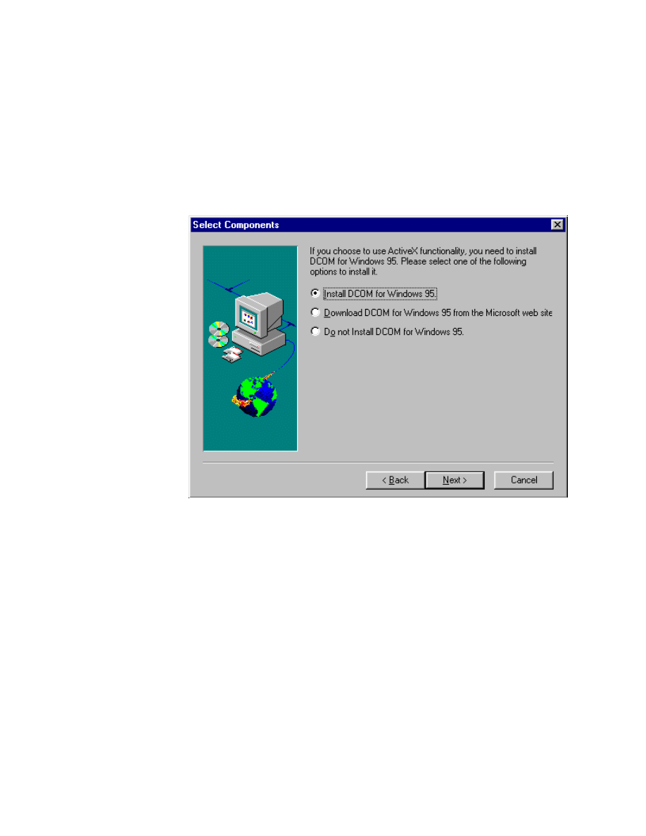
Appendix
LabVIEW Advanced I Course Manual
A-10
©
National Instruments Corporation
Installing DCOM on Windows 95
Unlike NT, Windows 95 does not come preinstalled with DCOM. You need
to install DCOM on your server and client machines by performing the
following steps:
1. If DCOM is not installed on your machine, you need
to install DCOM either by downloading it from
http://www.microsoft.com/oledev
or at the
time of LabVIEW installation, as shown below:
2.
DCOMCNFG.EXE
does not come preinstalled with Windows 95.
You need to install DCOMCNFG by downloading it from
http://www.microsoft.com/oledev
. Change the access control
from control panel/network to user-level access control for
DCOMCNFG to work.
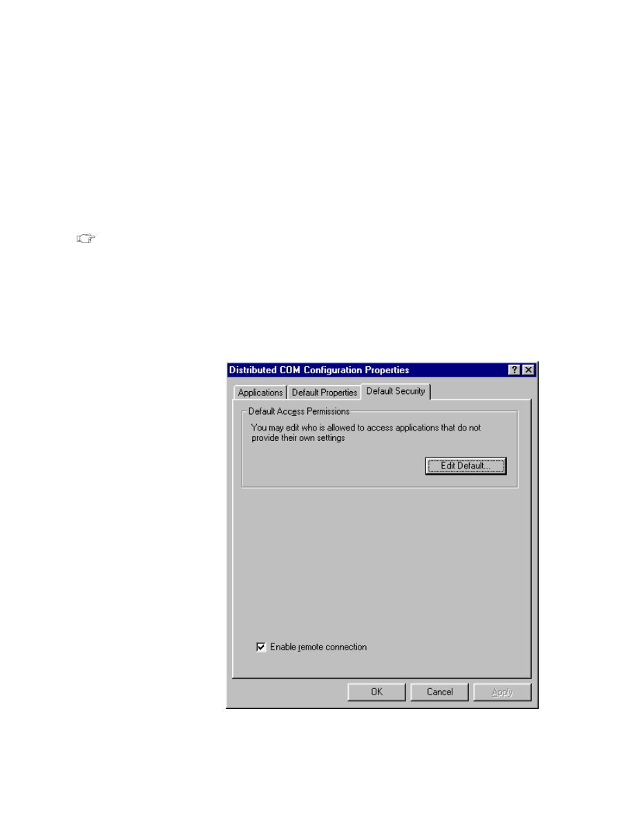
Appendix
©
National Instruments Corporation
A-11
LabVIEW Advanced I Course Manual
Configuring the Server on Windows 95
1. Install LabVIEW and run it at least once.
2. Run the DCOM Configuration Utility (
DCOMCNFG.EXE
) from the
command line or from Start » Run.
3. Click on Default properties. Enable DCOM if not already enabled. You
can also set the default authentication and impersonation levels here. It
is advisable to set the authentication to Connect and impersonation to
Identify. If you need to do nonsecure DCOM, you can set authentication
to None.
Note
If you set authentication to none, call security for the entire machine is turned
off. Any client will be able to call into any COM server running on this
machine.
4. Click on the Default Security tab. Check Enable Remote Connection.
You can also specify the default access permissions for all ActiveX
applications on the machine by clicking on the Edit Default button
under Default Access Permissions, as shown below:

Appendix
LabVIEW Advanced I Course Manual
A-12
©
National Instruments Corporation
5. Click on the Applications tab. Select LabVIEW Application and click
on Properties....
6. Switch to the Security page. You can customize which users or groups
of users can access an application. Choose the users/groups that are
allowed access to LabVIEW server. You can also choose to use default
permissions. If you do so, make sure you have provided access
permissions to the relevant users/groups in the Default Security page
mentioned in step 4.
7. Click OK and exit DCOMCNFG. You must reboot your machine for
changes to take effect.

Appendix
©
National Instruments Corporation
A-13
LabVIEW Advanced I Course Manual
Configuring the Client on Windows 95
1. If LabVIEW has not been installed and run on the client machine, you
should run the registration file shown below. This file,
lv50.reg
, is on
your course disk.
REGEDIT
HKEY_CLASSES_ROOT\LabVIEW.Application = LabVIEW Application
HKEY_CLASSES_ROOT\LabVIEW.Application\Clsid =
{9a872070-0a06-11d1-90b7-00a024ce2744}
;;;;;;;;;;;;;;;;;;;;;;;;;;;;;;;;;;;;;;;
; registration info LabVIEW.Application.5
HKEY_CLASSES_ROOT\LabVIEW.Application.5 = LabVIEW Application
HKEY_CLASSES_ROOT\LabVIEW.Application.5\Clsid =
{9a872070-0a06-11d1-90b7-00a024ce2744}
;;;;;;;;;;;;;;;;;;;;;;;;;;;;;
; registration info LabVIEW 5.0
HKEY_CLASSES_ROOT\CLSID\{9a872070-0a06-11d1-90b7-00a024ce2744} = LabVIEW
Application
HKEY_CLASSES_ROOT\CLSID\{9a872070-0a06-11d1-90b7-00a024ce2744}\ProgID =
LabVIEW.Application.5
HKEY_CLASSES_ROOT\CLSID\{9a872070-0a06-11d1-90b7-00a024ce2744}\VersionIndepend
entProgID = LabVIEW.Application
HKEY_CLASSES_ROOT\CLSID\{9a872070-0a06-11d1-90b7-00a024ce2744}\LocalServer =
labview.exe /Automation
HKEY_CLASSES_ROOT\CLSID\{9a872070-0a06-11d1-90b7-00a024ce2744}\LocalServer32 =
labview.exe /Automation
HKEY_CLASSES_ROOT\Interface\{9a872072-0a06-11d1-90b7-00a024ce2744} =
_Application
HKEY_CLASSES_ROOT\Interface\{9a872072-0a06-11d1-90b7-00a024ce2744}\ProxyStubCl
sid = {00020420-0000-0000-C000-000000000046}
HKEY_CLASSES_ROOT\Interface\{9a872072-0a06-11d1-90b7-00a024ce2744}\ProxyStubCl
sid32 = {00020420-0000-0000-C000-000000000046}
HKEY_CLASSES_ROOT\Interface\{9a872072-0a06-11d1-90b7-00a024ce2744}\TypeLib =
{9A872073-0A06-11D1-90B7-00A024CE2744}
HKEY_CLASSES_ROOT\Interface\{9a872074-0a06-11d1-90b7-00a024ce2744} =
VirtualInstrument
HKEY_CLASSES_ROOT\Interface\{9a872074-0a06-11d1-90b7-00a024ce2744}\ProxyStubCl
sid = {00020420-0000-0000-C000-000000000046}
HKEY_CLASSES_ROOT\Interface\{9a872074-0a06-11d1-90b7-00a024ce2744}\ProxyStubCl
sid32 = {00020420-0000-0000-C000-000000000046}
HKEY_CLASSES_ROOT\Interface\{9a872074-0a06-11d1-90b7-00a024ce2744}\TypeLib =
{9A872073-0A06-11D1-90B7-00A024CE2744}
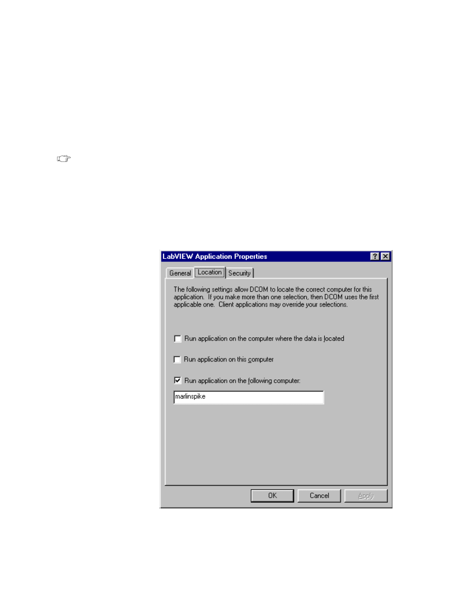
Appendix
LabVIEW Advanced I Course Manual
A-14
©
National Instruments Corporation
2. Run the DCOM Configuration Utility (
DCOMCNFG.EXE
) from the
command line or from Start » Run. This should bring up the DCOM
Configuration Tool.
3. Click on Default Properties. Enable DCOM if not already enabled. You
can also set the default authentication and impersonation levels here. It
is advisable to set the authentication to Connect and impersonation to
Identify. If you need to do nonsecure DCOM, you can set authentication
to None.
Note
If you set authentication to none, call security for the entire machine is turned
off. Any client will be able to call into any COM server running on this
machine.
4. Switch to the Applications page. Double-click on LabVIEW
Application and click on the Location tab. Uncheck Run application
on this computer. Check Run application on the following computer
and specify the server machine name as shown below:
5. Click OK and exit DCOMCNFG. You are ready to run LabVIEW on the
remote machine. You may need to reboot your machine.

Appendix
©
National Instruments Corporation
A-15
LabVIEW Advanced I Course Manual
D. Dynamic Data Exchange
Introduction
Dynamic Data Exchange (DDE) is a Microsoft Windows protocol for
communication between applications. Those applications can be on the
same computer or, using Networked DDE (NetDDE), on different
computers. DDE uses shared memory to exchange data between
applications, so the data actually is not passed between applications. A
common area of memory is created and two or more applications can
access the variables stored in that memory location. This section will
discuss how you can use LabVIEW to share data with other applications
via DDE.
DDE Background
Dynamic Data Exchange (DDE) is a protocol for exchanging data
between Windows applications—it is supported only by LabVIEW for
Windows 3.x, Windows NT, and Windows 95/98. Other requirements
for DDE are that both applications must be running and both must have
DDE support.
In TCP/IP communications, applications open a line of communication
and then transfer raw data. DDE works at a higher level, where
applications send messages to each other to exchange information. A
DDE connection is referred to as a conversation. Windows identifies
each conversation by a refnum, just as the TCP/IP connections were
identified by a unique connection ID number. If this number is altered,
the DDE conversation will not work and will generate errors.
A DDE client initiates a conversation with another application (a DDE
server) by sending a connect message. After establishing a DDE
conversation, the client can send commands to the server and change or
request the value of data that the server manages.
A client can request data from a server by a request or an advise. The
client uses a request to ask for the current value of the data. If a client
wants to monitor a value over a period of time, the client must request to
be advised of changes. By asking to be advised of data value, the client
establishes a link between the client and server through which the server
notifies the client when the data changes. The client can stop monitoring
the value of the data by telling the server to stop the advise link.
When the DDE communication for a conversation is complete, the client
sends a close conversation message to the server. DDE is most
appropriate for communication with standard off-the-shelf applications,
such as Microsoft Excel.

Appendix
LabVIEW Advanced I Course Manual
A-16
©
National Instruments Corporation
Services, Topics, and Data Items
With TCP/IP, the process you use is identified by its computer address
and a port number. With DDE, you identify the application you want to
talk to by referencing the name of a service and a topic. The server
decides on arbitrary service and topic names. A given server generally
uses its application name for the service, but not necessarily. That server
can offer several topics that it is willing to communicate. With Excel, for
example, the topic might be the name of a spreadsheet.
Each application that supports DDE has a different set of services,
topics, and data items about which it can talk. For example, two
spreadsheet programs can take very different approaches in how they
specify spreadsheet cells. To find out what is supported by a given
application, consult the documentation that came with that application.
Microsoft Excel, a popular spreadsheet program for Windows, has DDE
support. You can use DDE to send commands that tell Excel to open a
spreadsheet, send data to Excel, read data from Excel, or perform various
other tasks. You also can manipulate and read spreadsheet data by name.
With Excel, the service name is Excel. For the topic, you use the name
of an open document or the word System. If System is used, you can
request information about the status of Excel or send general commands
(commands that are not directed to a specific spreadsheet). For example,
with the topic System, Excel will talk about items such as Status, which
will have a value of Busy if Excel is busy, or Ready if Excel is ready to
execute commands. Topics is another useful data item you can use when
the topic is Status. Topics returns a list of topics Excel will talk about,
including all open spreadsheet documents and the System topic. Refer to
the Excel manuals to know more about using DDE to pass information
between LabVIEW and Excel.
Unless you are going to send a command to the server, you usually work
with data items about which the server is willing to talk. You can treat
these as a list of variables that the server allows you to manipulate. You
can change variables by name, supply a new value for the variable, or
request the values of variables by name.
Unlike TCP/IP (where you can send any type of data between
applications), the DDE protocol used by LabVIEW is ASCII-based and
transmission is terminated when a null byte is reached. If the binary data
has a null byte (00) in it, the transmission will end. This means that to
send numbers to another application via DDE, you must convert that
number to a string. In the same way, numbers received through a DDE
request or advise must be converted from the string format.
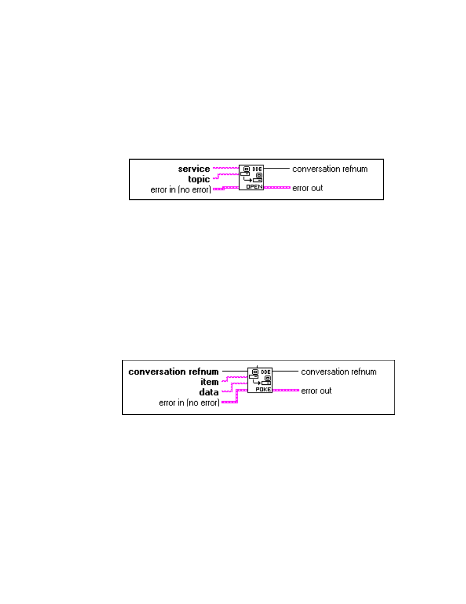
Appendix
©
National Instruments Corporation
A-17
LabVIEW Advanced I Course Manual
Using LabVIEW as a DDE Client
The DDE VIs are located in the Functions » Communication » DDE
palette. They give LabVIEW full DDE client capability. LabVIEW can
open DDE conversations and specify services, topics, and data items
from any other application that also supports DDE and is currently
running. Several of these VIs are described below.
DDE Open Conversation VI
The DDE Open Conversation VI establishes a connection between
LabVIEW and another application specified by service and topic.
conversation refnum is a unique number that identifies this DDE
connection. error in and error out clusters describe any error
conditions.
To use DDE, you first must establish a conversation using the DDE
Open Conversation VI. The VI must specify the service and topic. The
service usually corresponds to the name of the server application and the
topic to the active file.
DDE Poke VI
The DDE Poke VI tells the DDE server at conversation refnum to put
the value data at item. error in and error out clusters describe any error
conditions.
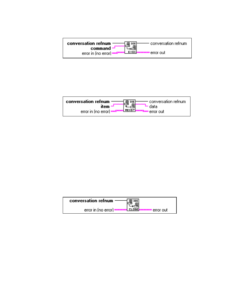
Appendix
LabVIEW Advanced I Course Manual
A-18
©
National Instruments Corporation
DDE Execute VI
The DDE Execute VI tells the DDE server at conversation refnum to
perform the command. error in and error out clusters describe any
error conditions.
DDE Request VI
The DDE Request VI tells the DDE server at conversation refnum to
return the data value of item. error in and error out clusters describe
any error conditions.
When the client has established a conversation, it can send data using the
DDE Poke VI, send commands using the DDE Execute VI, and obtain
data with the DDE Request VI. The DDE Request VI sends a DDE
message to the server every time it is called. The server then must check
the data requested and return it in another DDE message. If your VI
checks the value frequently, an advise protocol might be more efficient
than a request. You will learn about the advise protocol later in this
lesson.
DDE Close Conversation VI
The DDE Close Conversation VI ends the connection at conversation
refnum, closes all conversations, and releases the system resources
associated with the DDE VIs. error in and error out clusters describe
any error conditions.
The DDE VIs use error in and error out clusters as the TCP VIs do, so
you can use the Simple Error Handler VI in the Functions » Time &
Dialog palette to check for errors during a DDE conversation. The
following exercise uses the DDE VIs discussed above.
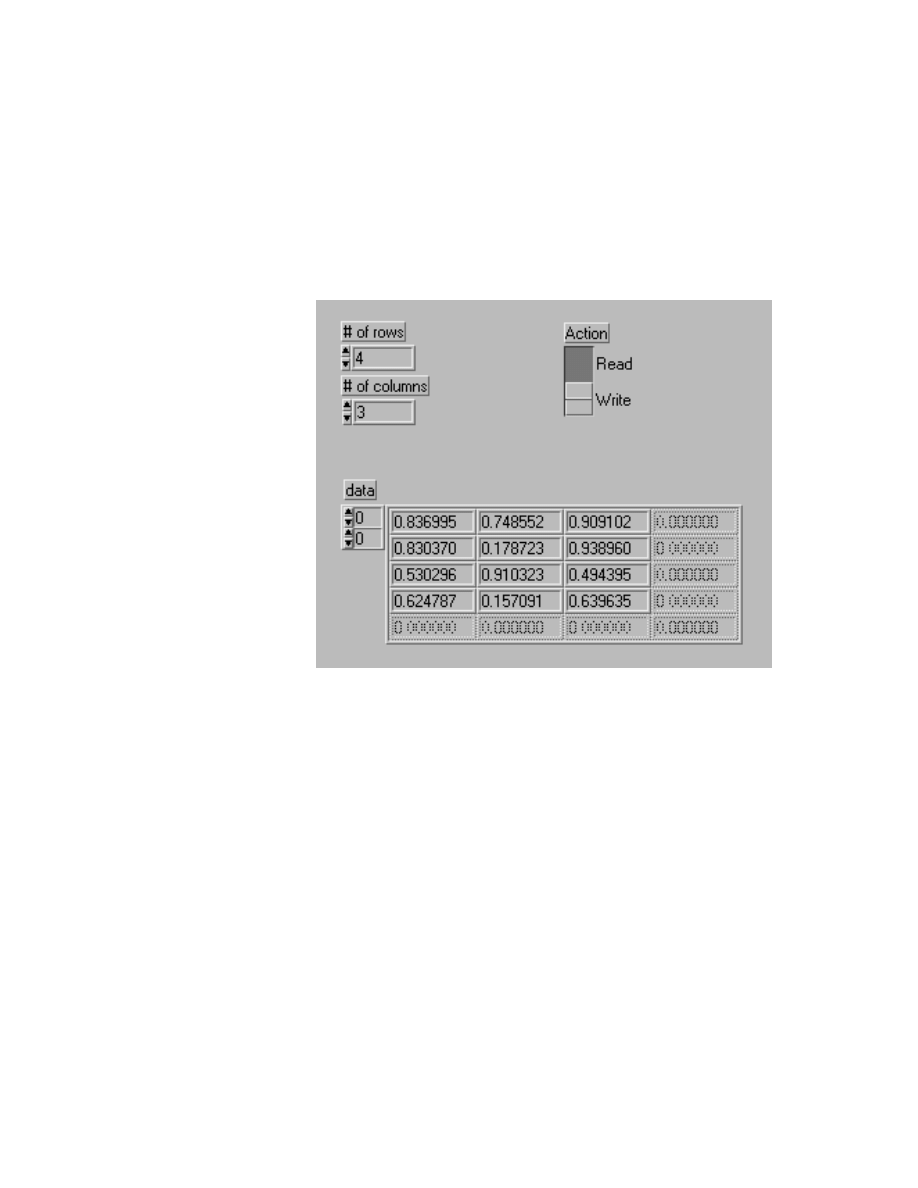
Appendix
©
National Instruments Corporation
A-19
LabVIEW Advanced I Course Manual
Exercise A-1
OBJECTIVE: To examine a VI that communicates with Excel through DDE.
You will examine a VI that either writes data to or reads data from a
spreadsheet. If you try to run this VI and you do not have Microsoft
Excel, Excel is not running, or the specified spreadsheet file is not open,
you will receive errors.
Front Panel
1. Open the DDE <--> Excel VI from
c:\exercises\LV_AdvI\
COMCLASS.LLB
. This VI is already
built for you.
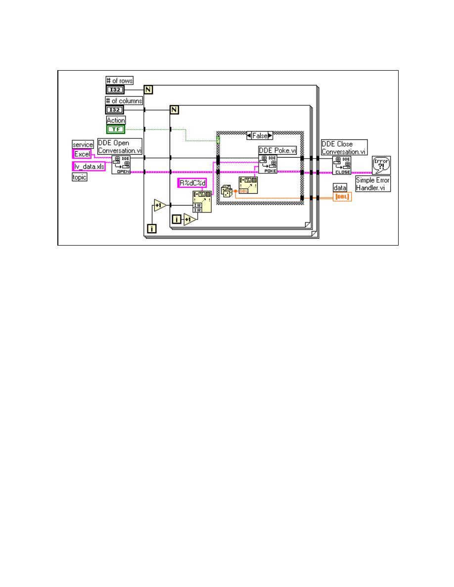
Appendix
LabVIEW Advanced I Course Manual
A-20
©
National Instruments Corporation
Block Diagram
2. Examine the block diagram.
First, LabVIEW establishes a DDE conversation with Excel using
the wordsheet
lv_data.xls
as the topic. If the user has selected
Write, then random numbers are generated and placed into the
spreadsheet using the DDE Poke VI at RxCy (R specifies row and C
specifies column), up to x rows and y columns as specified on the
front panel. If the user selected Read, data is read from the specified
rows and columns using the DDE Request VI. Notice how the data
values are sent or received through DDE as strings. Once all the data
has been read or written, then the connection is closed and errors are
checked using the Simple Error Handler VI.
3. If you have Microsoft Excel on your computer, launch it. Open the
spreadsheet file
lv_data.xls
from the
exercises\LV_Adv1
directory. Excel already must be running and the specified
spreadsheet file also must be open for this VI to work.
4. Go back to the DDE <--> Excel VI and run it. Go back to Excel and
examine the data in the spreadsheet. Return to LabVIEW and run the
VI a few more times with different options selected.
5. Close the VI and do not save any changes you may have made. Close
Excel and the spreadsheet file.
End of Exercise A-1
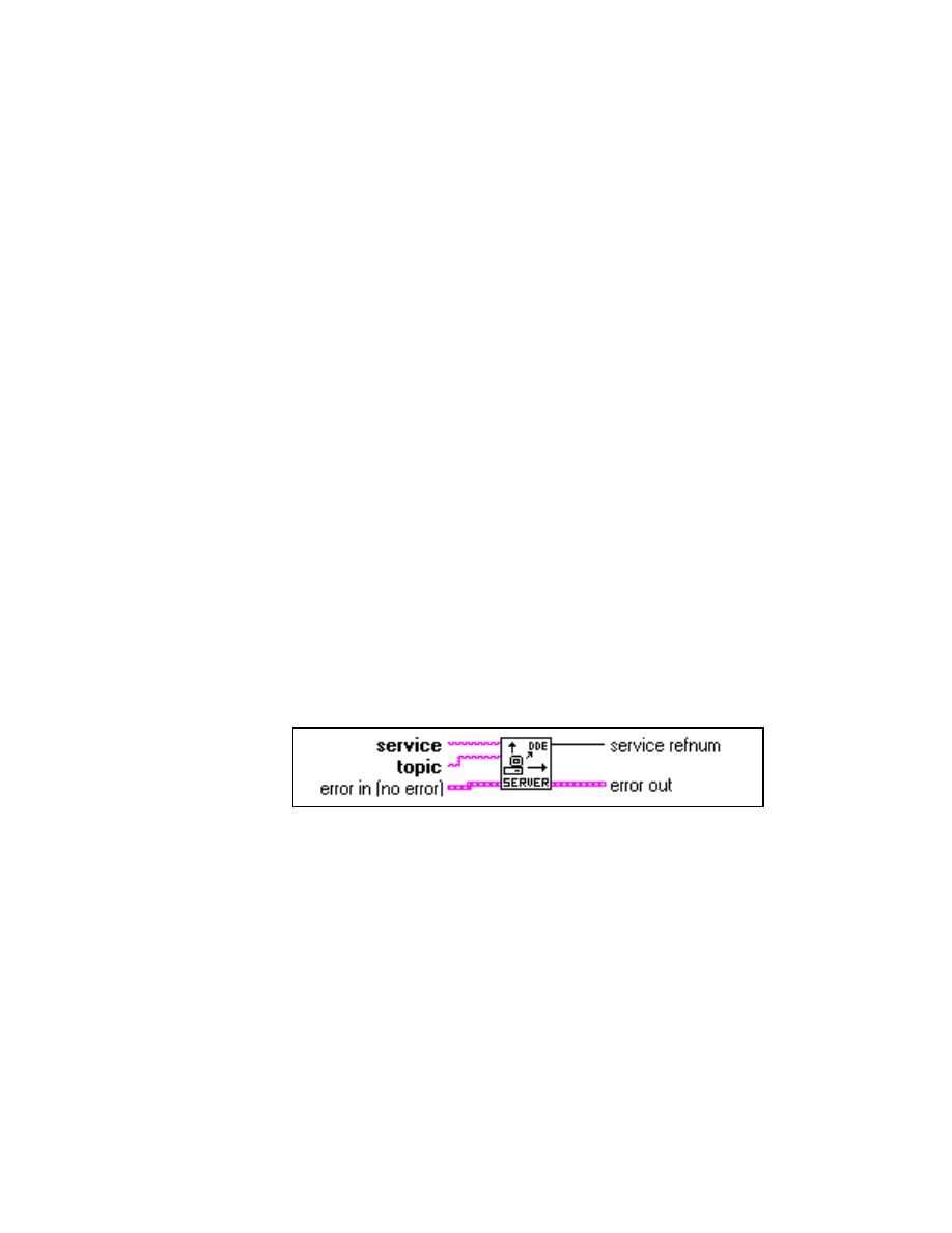
Appendix
©
National Instruments Corporation
A-21
LabVIEW Advanced I Course Manual
Using LabVIEW as a DDE Server
You can create LabVIEW VIs that act as servers for data items. A
LabVIEW VI indicates that it is willing to provide information regarding
a specific service and topic. LabVIEW can use any name for the service
and topic name. It might specify the service name to be the name of the
application (LabVIEW), and the topic name to be either the name of the
Server VI, or a general classification for the data it provides, such as
Lab Data.
The Server VI then registers data items for a given service. LabVIEW
remembers the data names and their values and handles communication
with other applications regarding the data. When the Server VI changes
the value of data that is registered for DDE communication, LabVIEW
notifies any client applications that have requested notification. In the
same way, if another application sends a Poke message to change the
value of a data item, LabVIEW changes this value.
You cannot use the DDE Execute command with a LabVIEW VI acting
as a server. To send a command to a VI, you must use the data items.
LabVIEW currently does not have anything similar to the System topic
provided by Excel. The LabVIEW application is not itself a DDE server
to which you can send commands or request status information.
The DDE Server VIs are located in the Functions » Communication »
DDE » DDE Server palette and are described below.
DDE Srv Register Service VI
The DDE Srv Register Service VI establishes a DDE service and topic
to which clients can connect. service refnum is a unique number that
identifies this DDE service. error in and error out clusters describe any
error conditions.
The first step to becoming a DDE server is to use the DDE Srv Register
Service VI to tell Windows what your service name and topic are going
to be. At this point, other applications can open DDE conversations with
your service. You can call the DDE Srv Register Service VI multiple
times with the same service name but different topic names to establish
multiple topics for one service.
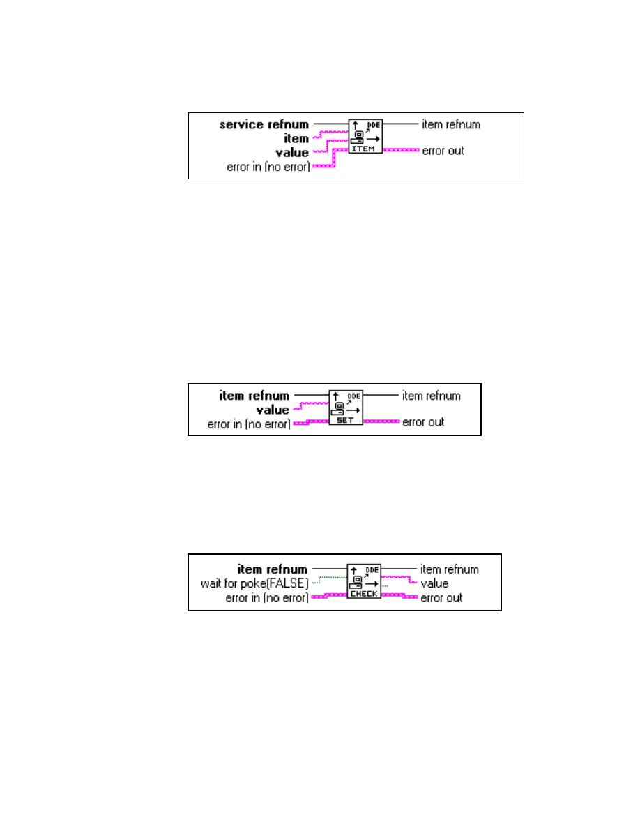
Appendix
LabVIEW Advanced I Course Manual
A-22
©
National Instruments Corporation
DDE Srv Register Item VI
The DDE Srv Register Item VI establishes a DDE item for the service
specified by service refnum. value is the initial value of the DDE item.
item refnum is a unique number that identifies this DDE item. error in
and error out clusters describe any error conditions.
After specifying your service and topic names, you can define items for
that service using the DDE Srv Register Item VI. After this call, other
applications can request or poke the item, as well as initiate advises on
that item. LabVIEW fully manages all these transactions.
DDE Srv Set Item VI
The DDE Srv Set Item VI changes the value of an item specified by item
refnum and informs all clients that have advises on that item. error in
and error out clusters describe any error conditions.
DDE Srv Check Item VI
The DDE Srv Check Item VI returns the value of an item identified by
item refnum. wait for poke specifies whether the VI should get the
current value and return immediately or wait until a client pokes the
value before returning. error in and error out clusters describe any
error conditions.
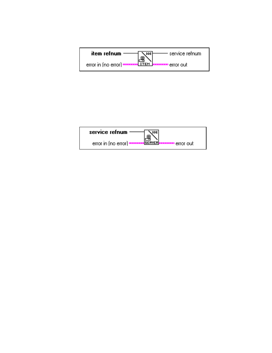
Appendix
©
National Instruments Corporation
A-23
LabVIEW Advanced I Course Manual
DDE Srv Unregister Item VI
The DDE Srv Unregister Item VI removes the item identified by item
refnum from its service. DDE clients no longer can access the item after
this VI completes. error in and error out clusters describe any error
conditions.
DDE Srv Unregister Service VI
The DDE Srv Unregister Service VI removes the service specified by
service refnum. error in and error out clusters describe any error
conditions.
You call the DDE Srv Unregister Item VI and the DDE Srv Unregister
Service VI to close down your DDE server. LabVIEW automatically
disconnects any client conversations connected to your server when
DDE Srv Unregister Service is called.
The following exercise uses LabVIEW as both a DDE server and a DDE
client.
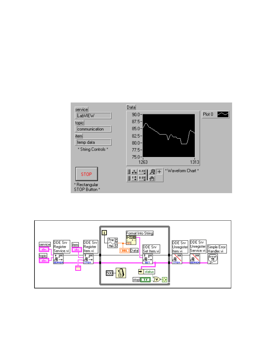
Appendix
LabVIEW Advanced I Course Manual
A-24
©
National Instruments Corporation
Exercise A-2
OBJECTIVE: To create a LabVIEW DDE server VI.
You will build a DDE server VI in LabVIEW that sends process data to
a DDE client VI. Both VIs will chart the data and you can change the rate
at which the client reads the data. This will show how timing is affected
by DDE conversations.
Part 1: DDE Server and Client VIs
Server Front Panel
1. Select New from the File menu and build the panel shown above.
Server Block Diagram
2. Build the block diagram shown above.
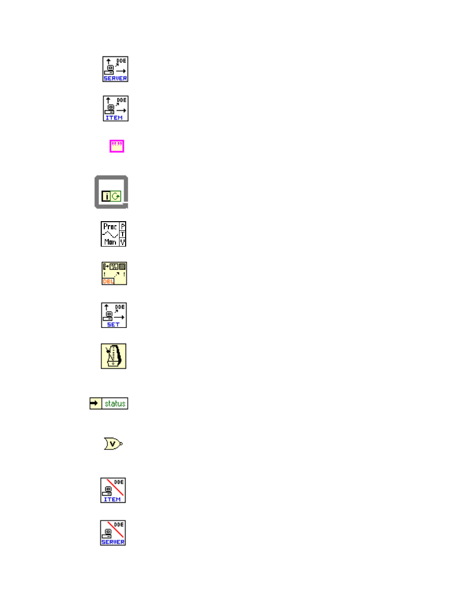
Appendix
©
National Instruments Corporation
A-25
LabVIEW Advanced I Course Manual
DDE Srv Register Service VI (Communication » DDE » DDE Server
palette). Establishes a DDE service to which a client can connect.
DDE Srv Register Item VI (Communication » DDE » DDE Server
palette). Establishes a DDE item for the service specified.
Empty String constant (String palette). Initializes the data item
specified to be an empty string.
While Loop structure (Structures palette). Used to run the VI
continuously until you press the STOP button or an error occurs.
Process Monitor VI (Select a VI... » c:\exercises\LV_AdvI\
COMCLASS.LLB). Generates simulated temperature data.
Format Into String function (String palette). Converts the temperature
value into and ASCII string.
DDE Srv Set Item VI (Communication » DDE » DDE Server palette).
Sets the data item to be the temperature string generated by the Process
Monitor.
Wait Until Next ms Multiple function (Time & Dialog palette).
Controls the timing such that a new data string is written every half
second. Pop up on the input of this function and choose Create Constant.
Enter the value of 500 into the resulting numeric constant.
Unbundle By Name function (Cluster palette). Unbundles the error
status from the error cluster. If an error has occurred, the loop will end
and the DDE conversation is closed.
Not Or function (Boolean palette). Tells the While Loop to continue
running if there is no error and the user has not pressed the STOP button.
DDE Srv Unregister Item VI (Communication » DDE » DDE Server
palette). Removes the specified item from service. DDE clients no
longer can access the item after this VI completes.
DDE Srv Unregister Service VI (Communication » DDE » DDE
Server palette). Removes the specified service. DDE clients no longer
can connect to this service, and all current conversations are closed.
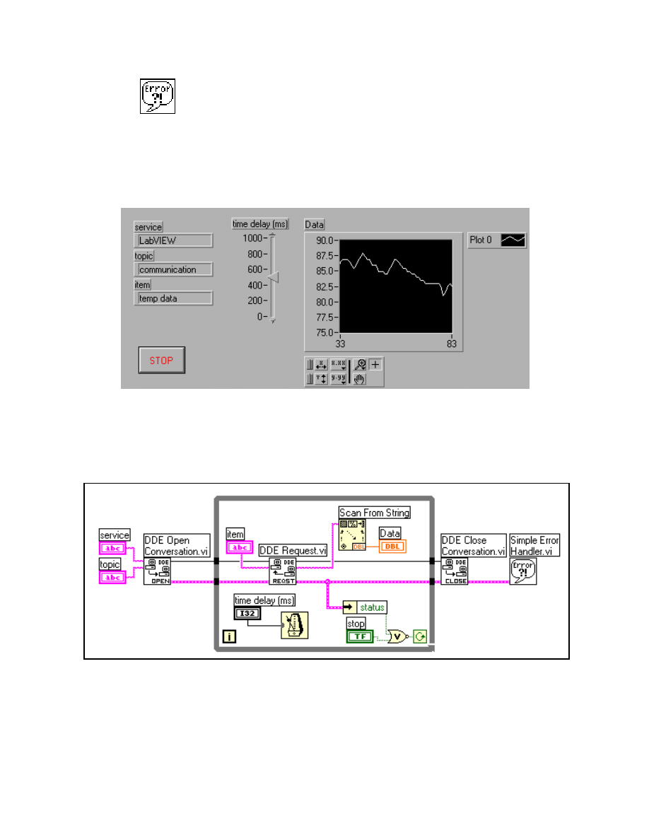
Appendix
LabVIEW Advanced I Course Manual
A-26
©
National Instruments Corporation
Simple Error Handler VI (Time & Dialog palette). Displays a dialog
box reporting any errors that have occurred.
3. Save this VI into
COMCLASS.LLB
and name it DDE Data Server.vi.
Do not close this VI, as you will need it later.
Client Front Panel
4. Open the DDE Data Client VI from the
COMCLASS.LLB
. This VI
already is built for you.
Client Block Diagram
5. Examine the block diagram. This VI uses the same DDE client VIs
discussed previously—DDE Open Conversation, DDE Request, and
DDE Close Conversation.
6. Run the DDE Data Server VI and then run the DDE Data Client VI.
The waveform charts on both panels should plot a new temperature
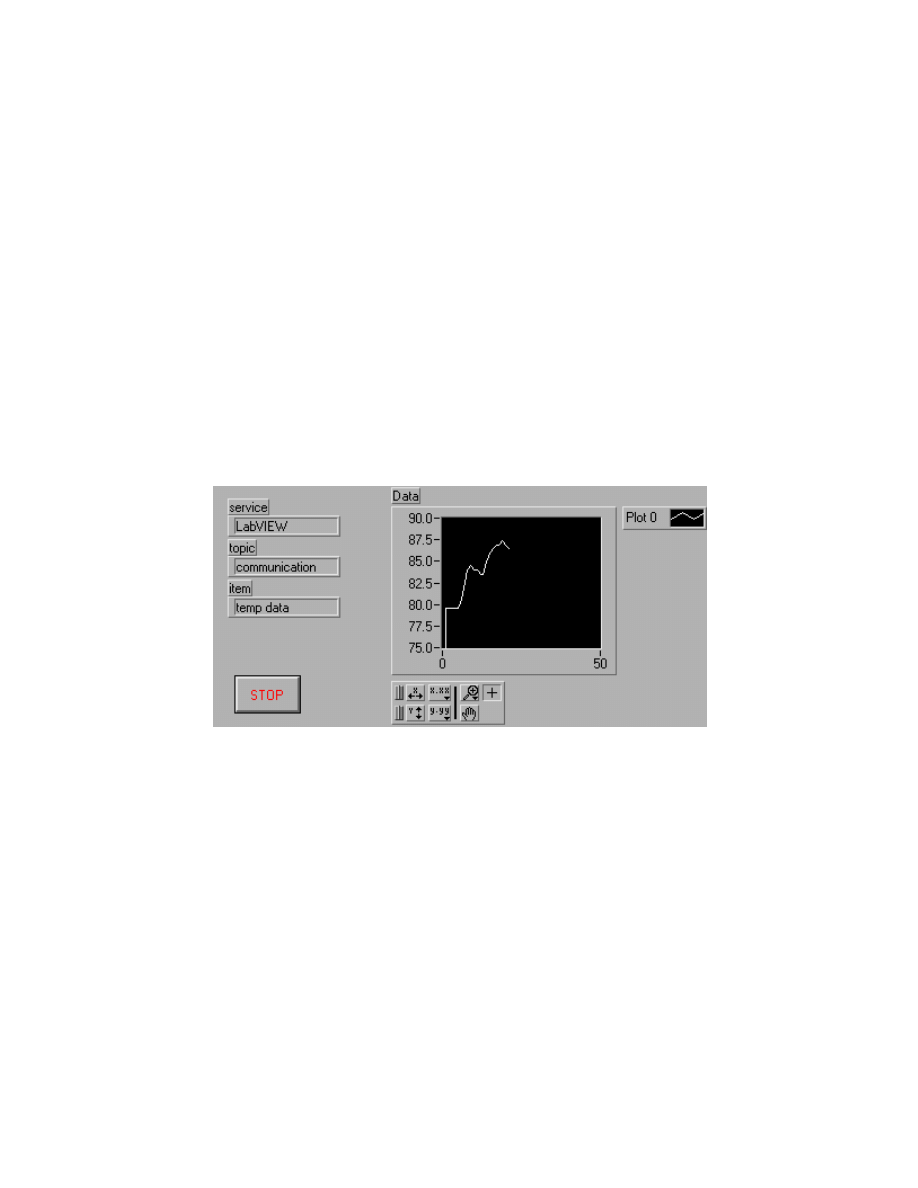
Appendix
©
National Instruments Corporation
A-27
LabVIEW Advanced I Course Manual
value every 500 ms. Continue to let the VIs run for a few more
seconds and adjust the time delay (ms) slider on the panel of the DDE
Data Client.
Notice that the data in the client VI will not match what is shown on
the server VI if the two VIs are not running at the same rate. In the
client VI, the DDE Request VI returns data immediately, regardless
of whether you have seen the data before. So if the server loops faster
than the client, data is lost; if the server loops slower than the client,
data is repeated.
One way to avoid duplicating data is to use the DDE Advise VIs to
request notification of changes in the value of a data item. You now
will modify the DDE Data Client VI to use the Advise VIs.
Part 2: DDE Advise VIs
Client Front Panel
7. Return to the DDE Data Client VI and modify the panel as shown
above by removing the time delay (ms) slider.
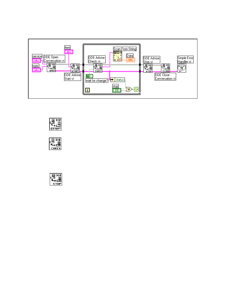
Appendix
LabVIEW Advanced I Course Manual
A-28
©
National Instruments Corporation
Client Block Diagram
8. Modify the block diagram as shown above.
DDE Advise Start VI (Communication » DDE palette). Initiates an
advise link with the specified DDE data item. Move the item string
terminal from inside to outside the While Loop to wire it to this VI.
DDE Advise Check VI (Communication » DDE palette). Checks a
previously defined advise value. Pop up on the DDE Request VI and
replace it with this VI. Then move the Wiring tool over this VI until the
wait for change? (FALSE) input is highlighted. Pop up and choose
Create Constant from the menu. Change to the Operating tool and click
the Boolean constant to the TRUE state.
DDE Advise Stop VI (Communication » DDE palette). Cancels the
advise link.
9. Save this VI as DDE Advise Data Client.vi in
COMCLASS.LLB
.
10. Type in the service, topic, and item strings. You can use any strings
as long as the client and server VIs use the same three strings. Run
the DDE Data Server VI and then run the DDE Advise Data Client
VI. The waveform charts on both panels should plot a new
temperature value every 500 ms.
The client/server VIs used in this exercise work well for monitoring
data. However, in these exercises there is no assurance that the client
receives all the data the server sends. Even with the DDE Advise
loop, if the client does not check for a data change frequently
enough, the client can miss a data value provided by the server.
In some applications, missed data is not a problem. For example, if
you are monitoring a data acquisition system, missed data may not
cause problems when you are observing general trends. In other

Appendix
©
National Instruments Corporation
A-29
LabVIEW Advanced I Course Manual
applications, you may want to ensure that no data is missed. One
major difference between TCP and DDE is that TCP queues data so
that nothing is missed and all is received in the correct order. DDE
does not provide this service.
However, in DDE you can set up a separate item, which the client
uses to acknowledge that it has received the latest data. You can then
update the acquired data item to contain a new point only when the
client acknowledges receipt of the previous data. This is beyond the
scope of this course, but you can observe the New Sync Client and
New Sync Server VIs from
EXAMPLES\COMM\DDEEXAMP.LLB
.
These VIs use this method to handshake data from the server to the
client.
11. Stop and close both VIs.
End of Exercise A-2

Appendix
LabVIEW Advanced I Course Manual
A-30
©
National Instruments Corporation
E. Networked DDE (NetDDE)
You can use DDE to communicate with applications on the same
computer or to communicate with applications on different computers
over a network. NetDDE is built into Windows for WorkGroups 3.1 or
greater, Windows 95/98, and Windows NT. The standard version of
Windows 3.1 does not support networked DDE unless you have an
add-on package from WonderWare. If you are using Windows 3.1 with
the WonderWare package, consult the WonderWare documentation on
how to use NetDDE. If you are using Windows for WorkGroups,
Windows 95, or Windows NT, use the following instructions:
Server Machine
Windows for WorkGroups
Add the following line to the [DDE Shares] section of the file
system.ini
on the server (application receiving DDE commands):
lvdemo = service_name,
topic_name,,31,,0,,0,0,0
Where:
•
lvdemo
can be any name.
•
service_name
is typically the name of the application, such as
Excel.
•
topic_name
is typically the specific file name, such as
sheet1
.
Windows 95/98
Note:
NetDDE is not started automatically by Windows 95/98. You
need to run the program
\WINDOWS\NETDDE.EXE
. (This
program can be added to the startup folder.)
To set up a NetDDE server on Windows 95/98:
1. Run
\WINDOWS\REGEDIT.EXE.
2. In the tree display, open the folder
My Computer\
HKEY_LOCAL_MACHINE\SOFTWARE\Microsoft\NetDDE\
DDE Shares
.
3. Create a new DDE Share by selecting Edit » New » Key and give it
the name
lvdemo
.
4. With the
lvdemo
key selected, add the required values to the share
as follows. (For future reference, these keys are just being copied
from the
CHAT$
share, but REGEDIT does not allow you cut, copy,
or paste keys or values.) Use Edit » New to add new values.

Appendix
©
National Instruments Corporation
A-31
LabVIEW Advanced I Course Manual
When you create the key, there will be a default value named
(Default) and a value of (value not set). Leave these values alone and
add the following:
5. Close
REGEDIT
and restart the machine. (NetDDE must be restarted
for changes to take effect.)
Windows NT
Launch
DDEShare.exe
, found in the
winnt/system32
directory.
Select from the Shares » DDE Shares » Add a Share… to register the
service name and topic name on the server.
Client Machine
On the client machine (application initiating DDE conversation), no
configuration changes are necessary.
Use the following inputs to DDE Open Conversation.vi:
Service:
\\computer-name\ndde$
Topic:
lvdemo
Where:
•
computer_name
specifies the name of the server machine.
•
lvdemo
matches the name specified in the
[DDE Shares]
section
on the server.
Value Type
Name
Value
Binary
Additional item count
00 00 00 00
String
Application
service_name
String
Item
service_name
String
Password1
service_name
String
Password2
service_name
Binary
Permissions1
1F 00 00 00
Binary
Permissions2
00 00 00 00
String
Topic
topic_name

Appendix
LabVIEW Advanced I Course Manual
A-32
©
National Instruments Corporation
For example, if you want two computers running LabVIEW to
communicate using networked DDE under Windows for WorkGroups,
the server needs to use LabVIEW for the service name, and a name, such
as
labdata
, for the topic. Assuming the computer name is
Lab
, the
client tries to open a conversation using the
\\Lab\ndde$
for the
service. For the topic the client can use a name of
remotelab
.
For this to work, you must edit the
SYSTEM.INI
file of the server
computer to have the following line in the
[DDEShares]
section:
remotelab=LabVIEW, labdata,,31,,0,,0,0,0
As you can see from the previous discussion, configuring a server
machine for NetDDE is difficult. If each setting is not typed exactly as
described, you will be unable to communicate using NetDDE. However,
a utility VI was created in LabVIEW that automatically configures the
registration table for a DDE server in Windows 95/98. The next exercise
describes that VI.
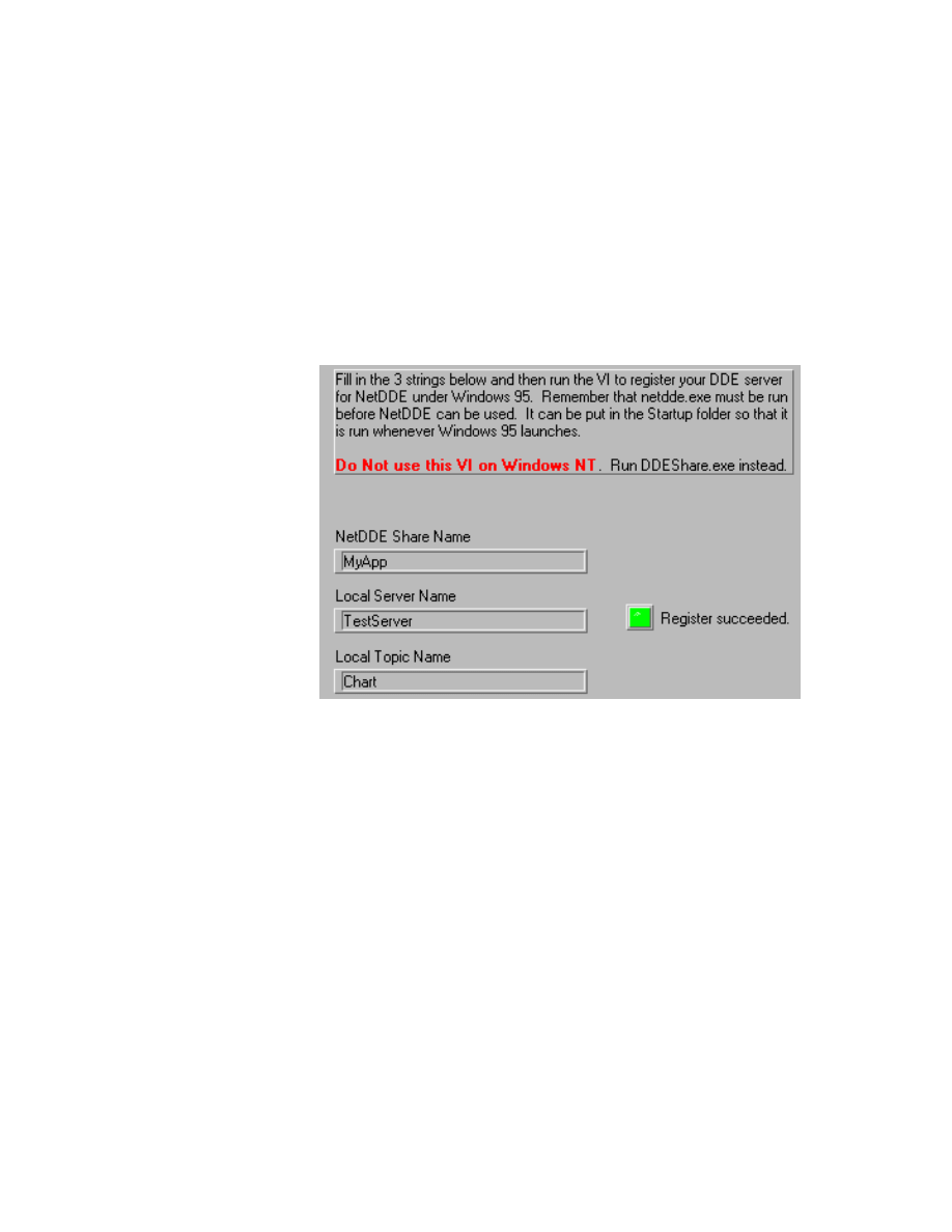
Appendix
©
National Instruments Corporation
A-33
LabVIEW Advanced I Course Manual
Exercise A-3
OBJECTIVE: To discuss a LabVIEW NetDDE server example in Windows 95/98.
To configure your computer to be a NetDDE server with LabVIEW, you
must change a number of settings in a registration table in Windows
95/98. This process can be tricky to do correctly by hand. Therefore, this
course includes a VI that performs the configurations automatically. You
will examine it here, and then we will discuss how the previous client
and server VIs can be used via NetDDE.
Front Panel
1. Open the Register NetDDE Server VI from
COMCLASS.LLB
. Its
front panel is shown above.
2. You will run this VI only once with the appropriate character strings
for the Share Name, Service, and Topic. If you examine the diagram,
notice how the table discussed earlier is built by the VI and sent to a
DLL named
advapi32.dll
.

Appendix
LabVIEW Advanced I Course Manual
A-34
©
National Instruments Corporation
3. Now assume you will use the VIs from the previous exercise, DDE
Data Server and DDE Advise Data Client, to send data from one
machine to another using NetDDE. These are the steps you perform:
End of Exercise A-3
Server
Client
1. Run the Register NetDDE Server VI.
2. Place
netdde.exe
in the Startup
Folder.
1. Place
netdde.exe
in the Startup Folder.
3. Restart the computer.
2. Restart the computer.
4. Launch LabVIEW and open the DDE
Data Server VI.
3. Launch LabVIEW and open the DDE
Advise Data Client VI.
5. Put the service and topic names that
were registered in step 1. Enter an item
string, and run the VI.
4. service =
\\server_machine_name\ndde$
The topic and item names will match the
names in the server VI and run the VI.

Appendix
©
National Instruments Corporation
A-35
LabVIEW Advanced I Course Manual
Summary
•
Dynamic Data Exchange (DDE) is a protocol for exchanging data
between Windows applications.
•
DDE is a higher-level protocol. A conversation is opened through a
service (usually the name of the server application) and a topic
(usually the name of a specific document), and then data items are
passed as variables. The server application defines the valid topics,
items, and format of the DDE conversation.
•
LabVIEW has full DDE client capability and can open conversations
and pass data items with DDE server applications, using VIs such as
DDE Open Conversation, DDE Execute, DDE Poke, DDE Request,
and DDE Close Conversation.
•
A DDE Request returns the data item value immediately, whether or
not that value has changed. You can use the Advise VIs to return data
values only when they have changed.
•
LabVIEW can act as a DDE server for data items. The server VIs are
in a separate palette and perform activities such as configuring
services, topics, and items and setting item values.
•
NetDDE is used for DDE communication between computers on a
network. There are several operating system-specific steps you must
perform to configure your computer and LabVIEW for NetDDE
communication. Refer to the LabVIEW Communications manual or
this course information for a listing of those steps.

Appendix
LabVIEW Advanced I Course Manual
A-36
©
National Instruments Corporation
F. The LabVIEW Internet Toolkit
The LabVIEW Internet Toolkit is a collection of VIs and networking
utilities you can use to explore opportunities provided by the Internet. These
VIs and utilities are written from the TCP/IP VIs and allow you to do things
such as have LabVIEW send e-mail, transfer data via FTP, or create web
pages that display front panel information. The Internet Toolkit contains the
four main VI categories discussed below.
FTP VIs
The FTP VIs allow you to programmatically upload and download files
from an FTP server with LabVIEW. The File Transfer Protocol (FTP) is a
utility in the suite of TCP/IP communications protocols. Users often share
data with other applications across a distributed environment. Sometimes a
remote server is used for archiving data, log files, etc. The FTP client allows
users to programmatically save files to and retrieve files from remote FTP
servers. The FTP protocol consists of commands sent by the client and
replies sent by the server over a control connection. Some commands (LIST,
NLST, RETR, STOR, STOU, APPE) require a second temporary
connection for transmitting data. This data connection is either active (the
client listens and the server connects) or passive (the server listens and the
client connects). The data connection can be interrupted by sending an
ABOR command.
The FTP VIs contain several levels of VIs to perform specific FTP
commands from LabVIEW. Each command of the basic FTP set has a
low-level VI. The intermediate VIs are used together with the low-level VIs
to establish and close FTP sessions and send sequences of commands.
High-level VIs perform the most commonly used operations, such as saving
or retrieving a file or multiple files. Refnums are used to define the FTP
sessions. The error cluster is used in the low-and intermediate-level VIs
only to propagate TCP/IP errors. The FTP protocol has provisions for
sending and receiving data in different formats to make data transfer more
efficient between systems that use the same format. A numeric parameter
returns the numeric part of a reply from the server, and a string parameter
returns the entire reply.
E-Mail VIs
The E-Mail VIs allow you to programmatically send mail with LabVIEW.
The Simple Mail Transfer Protocol (SMTP) is another utility in the suite of
TCP/IP communications protocol. Often, you have LabVIEW VIs running
remotely from you or other users who want to know the progress of an
experiment, know the results of a test, get an alert when something goes
wrong, or receive data generated by the VI. The E-Mail (SMTP client) VIs
allow users to programmatically send mail with LabVIEW. However, these

Appendix
©
National Instruments Corporation
A-37
LabVIEW Advanced I Course Manual
VIs would not be appropriate for alert messages that require an immediate
response, as sending e-mail can take too much time.
The high-level SMTP client VIs will perform the most common tasks such
as sending mail to a recipient with or without attachments. One important
feature of the SMTP client is the ability to support foreign character sets.
Characters from the extended character set are encoded to make the
messages MIME-compliant. The user can use foreign characters in the body
of the text and in the subject. The high-level VIs will be built out of
intermediate-level VIs that perform the standard minimum set of SMTP
commands as specified in RFC 821 (HELO, MAIL, RCPT, DATA, RSET,
NOOP, QUIT). The SMTP VIs will perform negotiations with the server,
send appropriate headers, convert the message to a MIME-compliant
format, and mail the message.
Telnet VIs
The Telnet client VIs allow other VIs to use Telnet connections the way they
use TCP to connect to a remote computer to execute some commands from
LabVIEW. For example, one computer acquires data that is processed on a
remote machine. LabVIEW can transfer the data to the remote machine
using FTP, connect to it using Telnet, and start a program to process the data.
When the process is finished, the LabVIEW transfers the results back to be
displayed on the first computer.
The Telnet protocol (RFC 854) is a TCP/IP communications protocol used
to transmit data with interspersed control information by providing a
general, bidirectional, 8-bit-oriented communications facility. The goal of
the Telnet protocol is to allow a standard method of interfacing terminal
devices and terminal-oriented processes to each other.
The Telnet connections are treated as objects, and VIs are included to open
and close Telnet connections and to read and write information. The data
associated with each Telnet connection consists of its connection refnum, a
buffer that contains data that has been read but still needs to be filtered, a
buffer containing data that has been read and filtered, and two semaphore
objects controlling read and write access to the Telnet connection.
WWW VIs
The World Wide Web (WWW) has become the premiere medium for
publishing and distributing information on the Internet. The HTTP server in
the LabVIEW Internet Toolkit allows users to perform four distinct tasks:
•
Display static documents saved on the user’s drive.
•
Display the panels of other VIs running on the system. This information
is transmitted in JPEG format and can also be available as an animated

Appendix
LabVIEW Advanced I Course Manual
A-38
©
National Instruments Corporation
image (Netscape Navigator). The VIs monitored do not need to be aware
of the HTTP server.
•
Develop CGI programs that generate data dynamically according to a
user request
•
Send animated images (Netscape Navigator) generated by Common
Gateway Interface (CGI) programs.
The HTTP Server is a top-level VI that always runs and listens on a
predefined TCP port (usually 80) for incoming connections. When a
connection is made, the server reads the request, performs the appropriate
action, and sends a response to the client. The request can be for a document
on the disk, a directory listing, the execution of a CGI program, a static or
animated image of a VI front panel, or an animated image generated
by a CGI.
CGIs are programs on the WWW that are executed on behalf of an HTTP
server. Users who write their own CGIs have libraries available consisting
of functions allowing access to CGI parameters, building HTML code,
using a Cookie Manager to store server side information, and other utilities.
CGI utility VIs allow CGI writers to easily extract parameters, convert to
and from HTML format, and perform operations on data passed to the CGI.
A cookie manager stores information associated with an IP address and
random key (cookie). CGIs use cookies to store pertinent information
between multiple connections. (HTTP is a stateless protocol and
connections usually do not know anything about previous connections.)
Cookies are used to implement “shopping baskets” in online stores. HTML
Utility VIs simplify the creation of HTML documents. They encode all
HTML 2.0 tags, making it easier to create HTML documents without an
intimate knowledge of HTML. Parameters to the CGI are stored in keyed
arrays. The array contains string elements, and the elements are indexed
with a key string. The library contains functions for building and accessing
keyed arrays.

Appendix
©
National Instruments Corporation
A-39
LabVIEW Advanced I Course Manual
G. Common Questions about Writing and Calling DLLs
1. When using the Call Library Function, why does LabVIEW crash
after the function finishes execution?
This is caused by using the incorrect calling convention. In the
configuration for the Call Library Function, there is an option to choose
either the default(stdcall) or C calling convention. Make sure that the
calling convention used in the DLL is the same as the calling convention
specified in the Call Library configuration. Also, check that the data
types specified in the Call Library Function match the data types in the
source code. Most C and C++ compiled DLLs use the C calling
convention. Windows API DLLs almost always use the default(stdcall)
calling convention.
2. Why is the number of parameters that can be passed to a function
in a DLL through the Call Library function limited to 29 singles or
14 doubles?
This problem is now obsolete in 32-bit Windows 95/98. It was a
limitation in 16-bit Windows due to the interface with 32-bit LabVIEW.
3. How do I pass structures, clusters, or non-numeric arrays to
a DLL?
You cannot pass structures, clusters, or non-numeric arrays to a DLL.
Depending on the data type, you may be able to pass the data by creating
a string or array of bytes that contains a binary image of the data that you
want to send. You can create binary data by typecasting data elements to
strings and concatenating them. Alternately, you could write a Code
Interface Node (CIN) instead of using a DLL. CINs do accept arbitrary
data structures.
4. When using Call Library Function, I keep getting a file dialog box
saying “Select a Library.”
a. Check that the path and DLL name or correct.
b. Check that the DLL is compiled correctly as a 32-bit DLL and not
some other file type. (Use Quickview in Windows 95 to verify
function name syntax in the DLL.)
5. When using Call Library Function to call a DLL, I receive a
“function not found” error, although the function is known to be
there.
a. Check the spelling of each function name. Use Quickview in win95
to examine DLL export functions to verify syntax. (Win32 and
Visual C++ DLL function names may be case sensitive depending
on how they were compiled.) When using Visual C++, the dumpbin
tool can be used to display information about a 32-bit DLL:
c:\msdev\bin\dumpbin -exports xxxx.dll

Appendix
LabVIEW Advanced I Course Manual
A-40
©
National Instruments Corporation
b. Check that each function is declared as extern “C” if you are using
the C++ compiler to prevent name mangling or name decoration.
c. Check that the Call Library Function in LabVIEW is configured for
the correct calling convention.
d. If using Borland compiler, turn off Case Sensitive Link and Case
Sensitive Imports and Exports when compiling the functions.
6. Why does the Call Library Function causes GPFs to occur?
a. This could be a side effect of not using the correct calling
convention. Ensure that the calling convention in the Call Library
Function matches that defined in the source code.
b. Check that the return and argument data types defined in the Call
Library Function configuration match the source code exactly.
c. If passing a pointer to an array, always initialize a buffer large
enough to hold any results placed in the buffer by the function.
7. What is the difference between the C and the standard C (stdcall)
calling conventions?
The C calling convention is the default calling convention for C and C++
programs. Arguments are passed from right to left. However, a called
function pops its own arguments from the stack. The only name
decoration is an underscore character (_) prefixed to the name. Because
the caller cleans up the stack, it can have variable argument functions.
The Default (standard C or __stdcall) calling convention is used to call
Win32 API functions. Parameters are passed by a function onto the
stack from right to left and are passed by value unless a pointer or
reference type is passed. An underscore (_) is prefixed to the name, and
the name is followed by the at-sign (@) character, followed by the
number of bytes (in decimal) in the argument list. Function arguments
are fixed, and a function prototype is required. Functions using this
calling convention return values the same way as functions using the C
calling convention.

Appendix
©
National Instruments Corporation
A-41
LabVIEW Advanced I Course Manual
H. Common Questions about CINs
1. When I compile the mult.c example using the nmake command, I
get an error that says:
mult.lvm(5): fatal error U1052: file '\ntlvsb.mak' not found
Stop.
The
cinToolsDir
is not properly defined. To define it in the makefile,
add the following line to the
mult.lvm
file:
CINTOOLSDIR = <path to cintools directory>
2. When I compile the mult.c example using nmake command, I get an
error that says:
NMAKE: fatal error U1073: don’t know how to make ‘mult.obj’
The path between nmake and the source files is not clearly defined.
Either place the source files into a directory that has a path defined in the
environment variables, set a path to the directory containing the source
files, or run nmake from the directory containing the source files.
3. When I run vcvars32 x86, I get memory related errors, (for
example, not having enough memory resources available or out of
memory).
Allocate more memory resources for the DOS shell by opening the
MS-DOS Prompt Properties window, selecting Program, and editing
the command line as follows:
command.com /e:1024
4. How do I include multiple external subroutines in the makefile for
a Windows NT CIN?
To include multiple external subroutines in Windows NT CINs, you
must specify them in your makefile. In your makefile (
.lvm
) you must
include the line
subrNames = (name of subroutine)
. To include
more than one external subroutine, you should list all external
subroutines separated by semicolons. For example, to include three
subroutines named add, subtract, and mult, add the following to your
CIN makefile:
subrNames = add; subtract; mult
.
5. What are the implications of having a CIN that is not thread-safe?
The problem is performance. The VI execution is interrupted to switch
to the user interface thread, run the CIN or DLL, and switch back. This
context switch time can be significant, especially if the CIN or DLL is
called often.

Appendix
LabVIEW Advanced I Course Manual
A-42
©
National Instruments Corporation
6. What does it mean if the CIN or Call Library Node on my block
diagram is orange?
This means the CIN or DLL is not thread-safe (reentrant). For operating
system DLLs or shared libraries, you can consult the vendor’s
documentation to determine if the system calls are reentrant. For DLLs
and CINs that you write, you must examine the source code to ensure
that no global resource can be modified from more than one thread at a
time. Watch especially for global variables, “static” variables, and
access to file or hardware I/O.
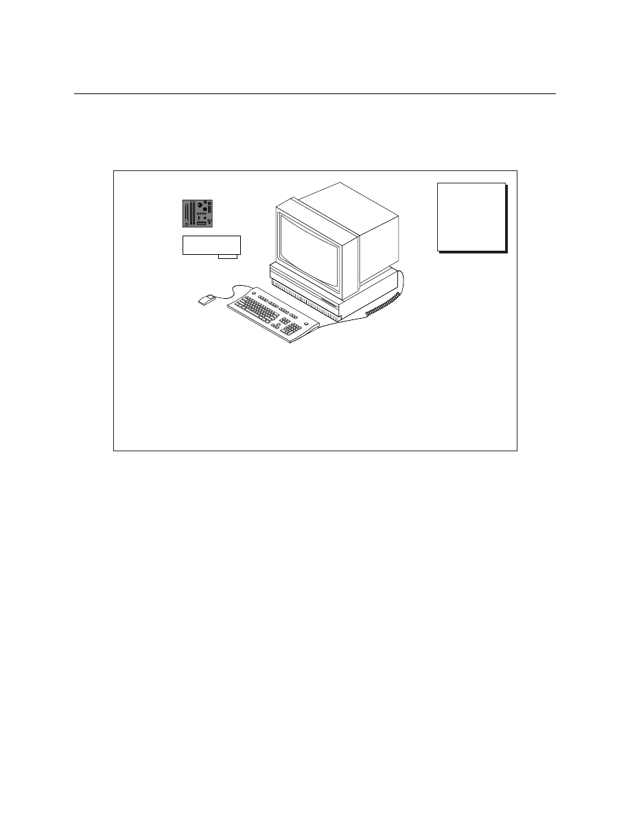
Appendix
©
National Instruments Corporation
A-43
LabVIEW Advanced I Course Manual
I. Instructor’s Notes
Windows
1. Each station consists of the following:
2. Copy the files from the PC disk accompanying this manual as described
in the Self-Paced Use section in the Student Guide.
3. Test the station by starting LabVIEW and running some of the
course VIs.
Module 1—No specific tests need to be run, as there is no extra
hardware or software with which to interface.
Module 2—Make sure both computers are connected with the Ethernet
cable. Then select the Control Panels » Networking option. Make sure
both computers have the TCP/IP protocol installed and both computers
have unique IP addresses. Reboot and launch LabVIEW. Run the Simple
Data Server example on one machine and the Simple Data Client
example on the other (LabVIEW » Examples » Comm » tcpex.llb) to
make sure the connections are good. Copy
mscal.ocx
from the
exercises\LV_AdvI
directory to the
Windows\System
directory.
Register this control in the registry by running the command
regsvs32
mscal.ocx
.
Module 3—Run one or more of the solutions provided to make sure you
can call CINs and DLLs in LabVIEW.
LabVIEW
Advanced I
Course
Manual
NI Software
•
LabVIEW for Windows FDS
Other items:
•
Instructor's machine contains Microsoft Visual C++
•
Microsoft Excel 97
•
A null-modem Ethernet cable connecting every two machines
(Module 2 only)
•
MIO Series DAQ board
•
DAQ Signal Accessory
DAQ Signal
Accessory
MIO Series
DAQ Board

Appendix
LabVIEW Advanced I Course Manual
A-44
©
National Instruments Corporation
Notes

Documentation Comment Form
National Instruments encourages you to comment on the documentation supplied with our products. This information
helps us provide quality products to meet your needs.
Title:
LabVIEW Advanced I Course Manual
Edition Date:
August 1998
Part Number:
321366C-01
Please comment on the completeness, clarity, and organization of the manual.
____________________________________________________________________________________________
____________________________________________________________________________________________
____________________________________________________________________________________________
____________________________________________________________________________________________
____________________________________________________________________________________________
____________________________________________________________________________________________
____________________________________________________________________________________________
____________________________________________________________________________________________
If you find errors in the manual, please record the page numbers and describe the errors.
____________________________________________________________________________________________
____________________________________________________________________________________________
____________________________________________________________________________________________
____________________________________________________________________________________________
____________________________________________________________________________________________
____________________________________________________________________________________________
____________________________________________________________________________________________
____________________________________________________________________________________________
Thank you for your help.
Name _______________________________________________________________________________________
Title ________________________________________________________________________________________
Company ____________________________________________________________________________________
Address _____________________________________________________________________________________
____________________________________________________________________________________________
E-mail Address _______________________________________________________________________________
Phone ( ___ )____________________________________ Fax ( ___ ) ___________________________________
Mail to:
Technical Publications
Fax to:
Technical Publications
National Instruments Corporation
National Instruments Corporation
6504 Bridge Point Parkway
512 795 6837
Austin, Texas 78730-5039

Course __________________________________________________________________________________________________________
Austin
Onsite
Regional
Location ____________________________________________
Instructor__________________________________________________________________
Date ____________________________
STUDENT
INFORMA
TION
INSTRUCTOR
COURSE
© Copyright 1994 National Instruments Corporation. All rights reserved.
280104B-01
071594
Course Evaluation
NATIONAL
INSTRUMENTS
™
The Software is the Instrument
®
(Optional)
Name ____________________________________________________________________________________________________________________
Company ______________________________________________________ Phone __________________________________________________
Please evaluate the instructor by checking the appropriate circle.
Outstanding Good Okay Poor Unsatisfactory
Instructor’s ability to communicate the material
Instructor’s sensitivity to class needs
Instructor’s knowledge of the subject matter
Instructor’s preparation for the class
Instructor’s presentation skills
Training facility quality Training equipment quality
The course length was Too Long Just Right Too Short
The detail of topics covered in the course was Too Much Just Right Not Enough
The course material was clear and easy to follow. Yes No Sometimes
Did the course cover material as advertised? Yes No
I had the skills or knowledge I needed to attend this course. Yes No If no, how could you have been better prepared for the course?
_________________________________________________________________________________________________________________________
The course met my objectives. Yes No If no, please explain. __________________________________________________________
_________________________________________________________________________________________________________________________
What were the strong points of the course?__________________________________________________________________________________________________
_____________________________________________________________________________________________________________________________________
What part(s) of the course need to be expanded?_____________________________________________________________________________________________
_____________________________________________________________________________________________________________________________________
What part(s) of the course need to be condensed or removed?__________________________________________________________________________________
_____________________________________________________________________________________________________________________________________
What needs to be added to the course to make it better? ______________________________________________________________________________________
_____________________________________________________________________________________________________________________________________
Comments/Ideas _______________________________________________________________________________________________________________________

Document Outline
- Title
- Address
- Contents
- Module I - Memory Management and Multithreading
- Module 2 - Connectivity
- Module 3 - Calling External Functions
- Module 1 Exercises
- Module 2 Exercises
- Module 3 Exercises
- Appendix
- A. Application Notes
- B. The LabVIEW Style Guide
- C. Remote Automation Using DCOM
- D. Dynamic Data Exchange
- Exercise A-1
- Exercise A-2
- E. Networked DDE (NetDDE)
- Exercise A-3
- F. The LabVIEW Internet Toolkit
- G. Common Questions about Writing and Calling DLLs
- H. Common Questions about CINs
- I. Instructor’s Notes
- Documentation Comment Form
- Course Evaluation
Wyszukiwarka
Podobne podstrony:
Polish Advanced Course
19 Dutch Advanced Course
Polish Advanced Course
10 Russian Advanced Course
Advanced Corel Draw Course
( English Course) Advanced Vocabulary In Context, Phrasal Verbs IPA6PICIZDRGFO2NFJ55HMMLGXOS6FAWJ55
English Essays Writing Course for Advanced Students 2
english essays writing course for advanced students
Longman 2005 Advanced Expert CAE Coursebook Answer Key 114p
Molenda, Marek; Kiermasz, Zuzanna Dictionary skills in advanced learners’ coursebooks — Materials s
Course hydro pl 1
Advanced Polyphthalamide (PPA) Metal Replacement Trends
Marketing Management Course
Advanced Mechanics in Robotic Systems (Springer 2011 Ed1)
więcej podobnych podstron