
C102632-0 page 1 of 16
26.3.2007
© The information contained in this document is the sole property of Steerprop Ltd. any reproduction or disclosure in part or whole without written permission is prohibited.
DOC-1017-1
Steerprop
SP20 / W0064-89
Propulsor
Captain’s Book
Operation Manual
Revision history:
REV. DATE MODIFIER DESCRIPTION
0 26.3.2007
AaNi Created
A
B
C
D
E
F

C102632-0 page 2 of 16
26.3.2007
© The information contained in this document is the sole property of Steerprop Ltd. any reproduction or disclosure in part or whole without written permission is prohibited.
DOC-1017-1
1.
SYSTEM STARTING ............................................................................................................................ 3
1.1.
P
REPARATION
................................................................................................................................... 3
1.2.
R
EADY TO OPERATION
..................................................................................................................... 3
1.2.1.
Auxiliary systems ..................................................................................................................... 3
1.2.2.
Control system supply (engine room)...................................................................................... 3
1.2.3.
Local control selection ............................................................................................................ 3
1.3.
C
ONTROL SYSTEM TEST
................................................................................................................... 4
1.3.1.
Remote controls from Wheelhouse .......................................................................................... 4
1.3.2.
Alarms ..................................................................................................................................... 4
1.4.
S
TARTING
......................................................................................................................................... 4
1.4.1.
Propulsor motor and drive ...................................................................................................... 4
1.4.2.
Propulsor (wheelhouse) .......................................................................................................... 4
2.
OPERATION .......................................................................................................................................... 5
2.1.
B
ASIC OPERATION PRINCIPLE
........................................................................................................... 5
2.1.1.
Zero position............................................................................................................................ 6
2.1.2.
Ahead....................................................................................................................................... 7
2.1.3.
Astern ...................................................................................................................................... 8
2.1.4.
Turning on spot ....................................................................................................................... 9
2.1.5.
Side step..................................................................................................................................10
2.1.6.
Braking with two propulsors ..................................................................................................11
2.1.7.
Braking with one propulsor....................................................................................................12
2.2.
S
ERVICE AND DIAGNOSTIC FUNCTIONS AT ENGINE ROOM DISPLAY
SED .......................................13
2.2.1.
Intelligent self diagnostic system (SDS) .................................................................................13
3.
FAILURE SITUATIONS......................................................................................................................14
3.1.
A
LARM INDICATIONS
......................................................................................................................14
3.1.1.
Service manual .......................................................................................................................14
4.
EMERGENCY OPERATION..............................................................................................................15
4.1.
L
OCAL CONTROL
,
STEERING
(S
TEERABLE PROPULSORS
)................................................................15
4.1.1.
Local control selection ...........................................................................................................15
4.1.2.
Steering...................................................................................................................................15
4.1.3.
Propulsor angle indication.....................................................................................................15
4.1.4.
Remote control selection ........................................................................................................15
4.2.
P
ROPULSOR MECHANICAL TURNING
(S
TEERABLE
P
ROPULSOR
) .....................................................15
4.2.1.
Disc brake open......................................................................................................................15
4.2.2.
Turning from motor shaft end.................................................................................................15
5.
PROPULSOR STOPPING ...................................................................................................................16

C102632-0 page 3 of 16
26.3.2007
© The information contained in this document is the sole property of Steerprop Ltd. any reproduction or disclosure in part or whole without written permission is prohibited.
DOC-1017-1
1. S
YSTEM STARTING
1.1. P
REPARATION
Check at least following systems
• Main
supplies
• Auxiliary
supplies
• Control system supplies
• Back-up
supplies
• Ship automation systems
• Cooling
systems
• Shafting
• Propulsor
Are in starting condition
1.2. R
EADY TO OPERATION
Check at least following systems
• Main
supplies
• Auxiliary
supplies
• Control system supplies
• Back-up
supplies
• Ship automation systems
• Cooling
systems
• Shafting
• Propulsor
Are ready for operation
1.2.1. A
UXILIARY SYSTEMS
1.2.1.1. S
TEERING GEAR
(
PROPULSOR ROOM
)
Check that steering gear inverters are ready and have no alarms.
1.2.1.2. L
UBRICATION PUMP
(
PROPULSOR ROOM
)
Check that lubrication pump inverter is running and has no alarms.
1.2.2. C
ONTROL SYSTEM SUPPLY
(
ENGINE ROOM
)
Check, that control system supply switch SS01 at SCU/SMU is “ON”. The indication
lamps SH01 at control stations should lit.
1.2.3. L
OCAL CONTROL SELECTION
Check, that local control selection switch at SCU is “Remote” (Steerable Propulsors).
Non-Steerable Propulsor is always at remote control.

C102632-0 page 4 of 16
26.3.2007
© The information contained in this document is the sole property of Steerprop Ltd. any reproduction or disclosure in part or whole without written permission is prohibited.
DOC-1017-1
1.3. C
ONTROL SYSTEM TEST
1.3.1. R
EMOTE CONTROLS FROM
W
HEELHOUSE
Check the following systems:
• Main control system
• Back-up control system
• Displays
• Alarm
system
1.3.2. A
LARMS
Check, that there are no active alarms and no other failure indications.
If the lubrication pump is not yet started, there could be “Lubrication pressure alarm”.
1.4. S
TARTING
1.4.1. P
ROPULSOR MOTOR AND DRIVE
Check, that system is working and is ready for operation. Check, that there are no
active alarms and no other failure indications.
1.4.2. S
TARTING SEQUENCE
• Start
Steerprop
• Wait 15 s
• Start propeller motor drive
1.4.3. P
ROPULSOR
(
WHEELHOUSE
)
Start both units independent. Then the propulsor lubrication pump will start and control
system will run.
The remote start is through remote control system (not delivered by Steerprop).
Check, that there are no active alarms. If the propulsor give alarm, interrupt the starting
procedure, check the reason for the alarms and fix it before continuing the starting
procedure.
C102632-0 page 5 of 16
26.3.2007
© The information contained in this document is the sole property of Steerprop Ltd. any reproduction or disclosure in part or whole without written permission is prohibited.
DOC-1017-1
2. O
PERATION
2.1. B
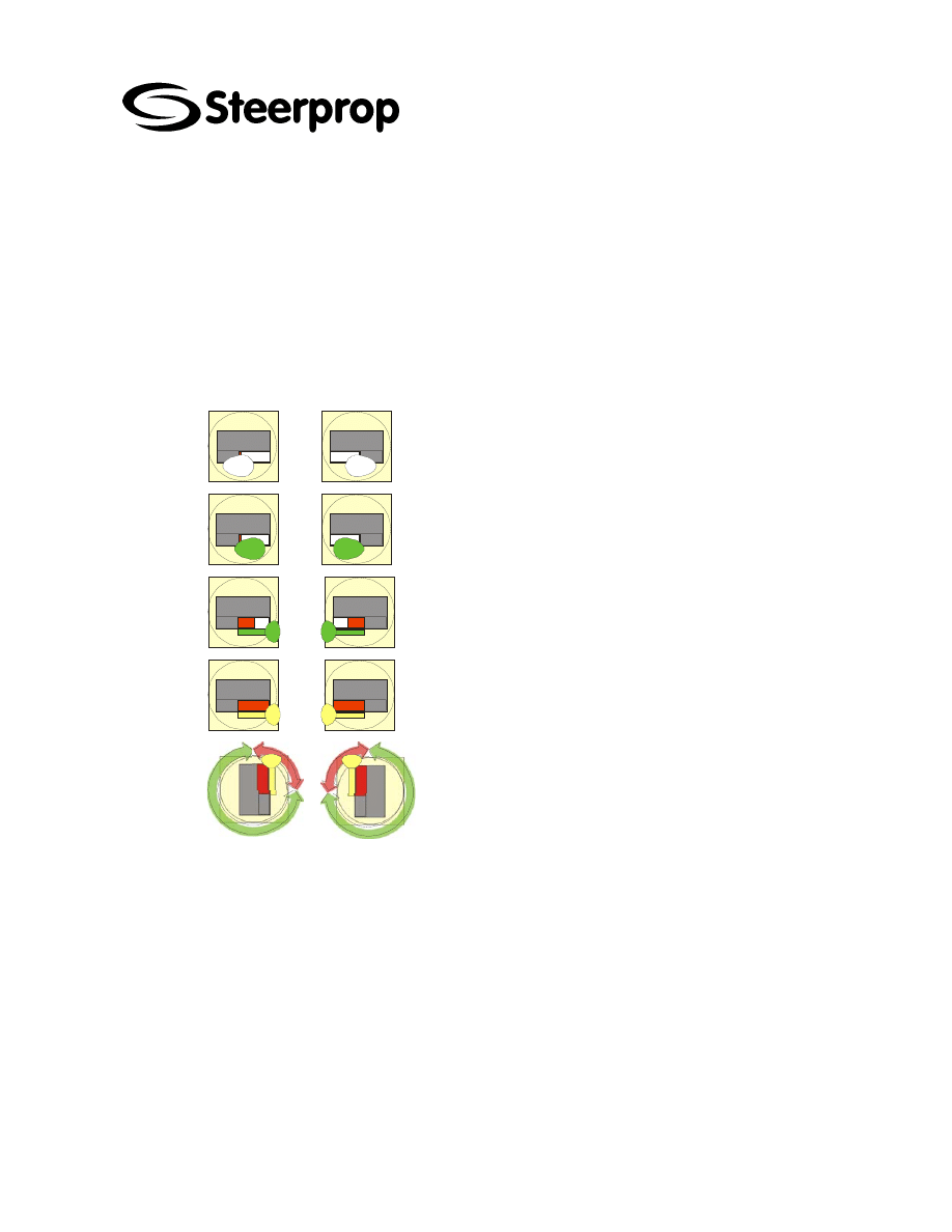
ASIC OPERATION PRINCIPLE
This chapter gives the basic advice on how to use the Steerprop propulsors to obtain a
specific motion to the vessel. It should be noted that each and every vessel is different
and that depending on vessel size, main dimensions, dimension ratios, hull form,
engine power, propeller size etc. the effect of a specific control movement is different
from vessel to vessel.
Thus the crew need to familiarize themselves with the vessel, before starting real
operations.
Propeller stopped
Low propeller rpm
Medium propeller rpm
Full propeller rpm
Steering angle
Full propeller rpm
C102632-0 page 6 of 16
26.3.2007
© The information contained in this document is the sole property of Steerprop Ltd. any reproduction or disclosure in part or whole without written permission is prohibited.
DOC-1017-1
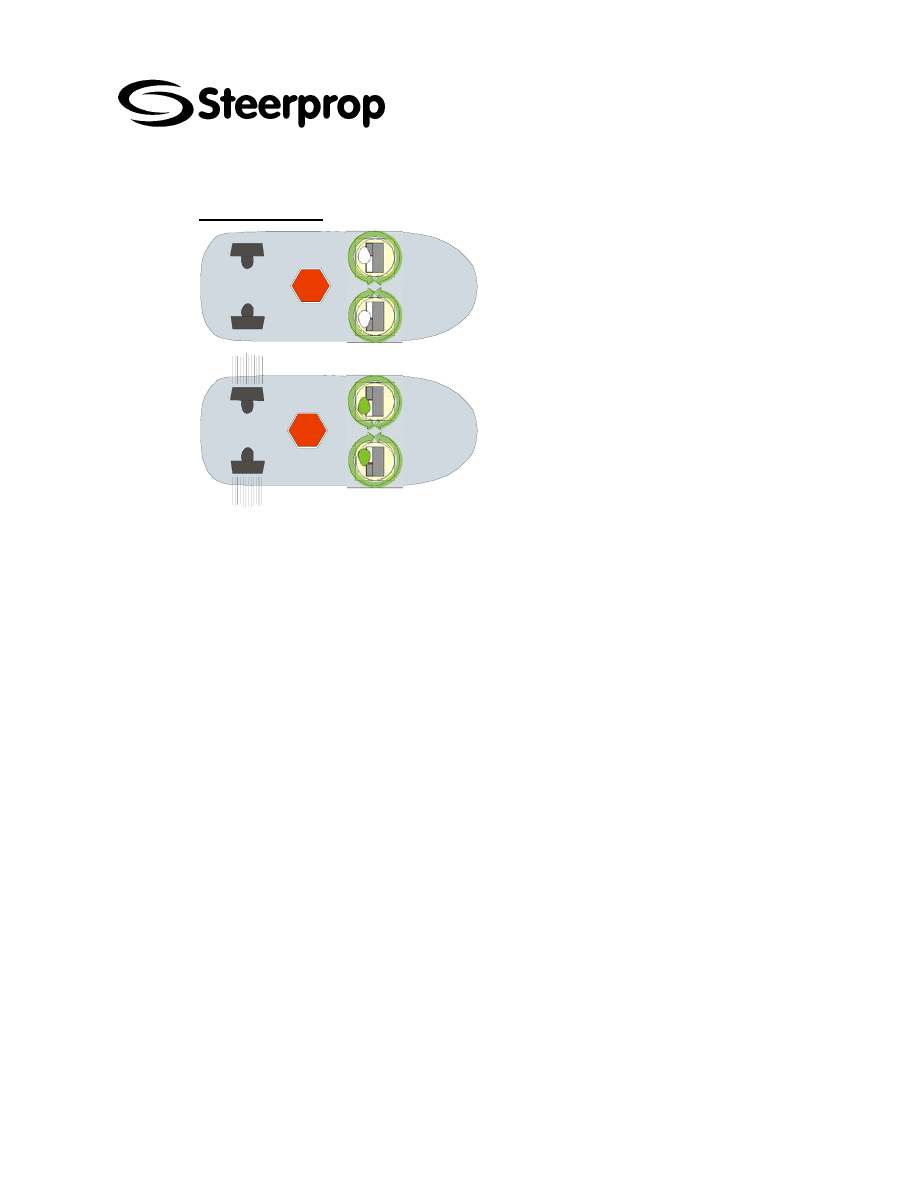
2.1.1. Z
ERO POSITION
STOP
◊ BASIC STARTING CONDITION
The Steerprop propulsors should
always be turned outwards before
stopping and starting, to avoid
propulsive forces at start-up.
STOP
◊ POSITION KEEPING
Both prime movers should run at
equal power, for position keeping. Can
be used at any power.
Turn on the spot possible by
increasing power on one of the
propulsors.
For ahead running turn both control
levers slowly forward - for astern
running turn both control levers slowly
aft.
C102632-0 page 7 of 16
26.3.2007
© The information contained in this document is the sole property of Steerprop Ltd. any reproduction or disclosure in part or whole without written permission is prohibited.
DOC-1017-1
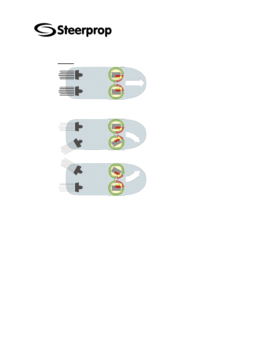
2.1.2. A
HEAD
◊ STRAIGHT AHEAD
From zero position turn the control
levers slowly forward until straight
ahead. Both prime movers should run at
equal power. Can be used at any
power.
Vessels with same-handed propellers
may require a small counter-angle to
run a straight course.
◊ STARBOARD TURN
Use only one propulsor to avoid over-
steering. The use of starboard (inner)
propulsor is the most efficient way (port
propulsor also turns the vessel to
starboard).
◊ PORT TURN
Use only one propulsor to avoid over-
steering.
The use of port (inner) propulsor is the
most efficient way (starboard propulsor
also turns the vessel to port).
C102632-0 page 8 of 16
26.3.2007
© The information contained in this document is the sole property of Steerprop Ltd. any reproduction or disclosure in part or whole without written permission is prohibited.
DOC-1017-1
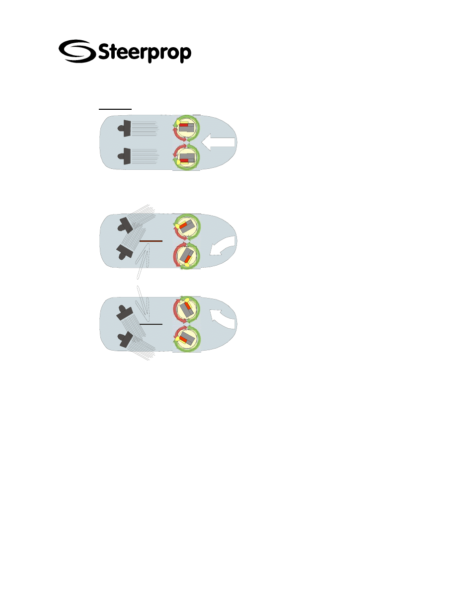
2.1.3. A
STERN
◊ STRAIGHT ASTERN
From zero position, turn the control levers
slowly aft until straight astern. Both prime
movers should run at equal power. Can
be used at any power.
Vessels with same-handed propellers
may require a counter-angle to run a
straight course and may encounter course
instability at high speeds.
◊ STARBOARD TURN ASTERN
Use both propulsors to improve the
steering force. The
starboard thruster should be turned to
avoid the propeller wash to hit the skeg
and cause counter-forces.
◊ PORT TURN ASTERN
Use both propulsors to improve the
steering force. The port thruster should
be turned to avoid the propeller wash to
hit the skeg and cause counter-forces.
C102632-0 page 9 of 16
26.3.2007
© The information contained in this document is the sole property of Steerprop Ltd. any reproduction or disclosure in part or whole without written permission is prohibited.
DOC-1017-1
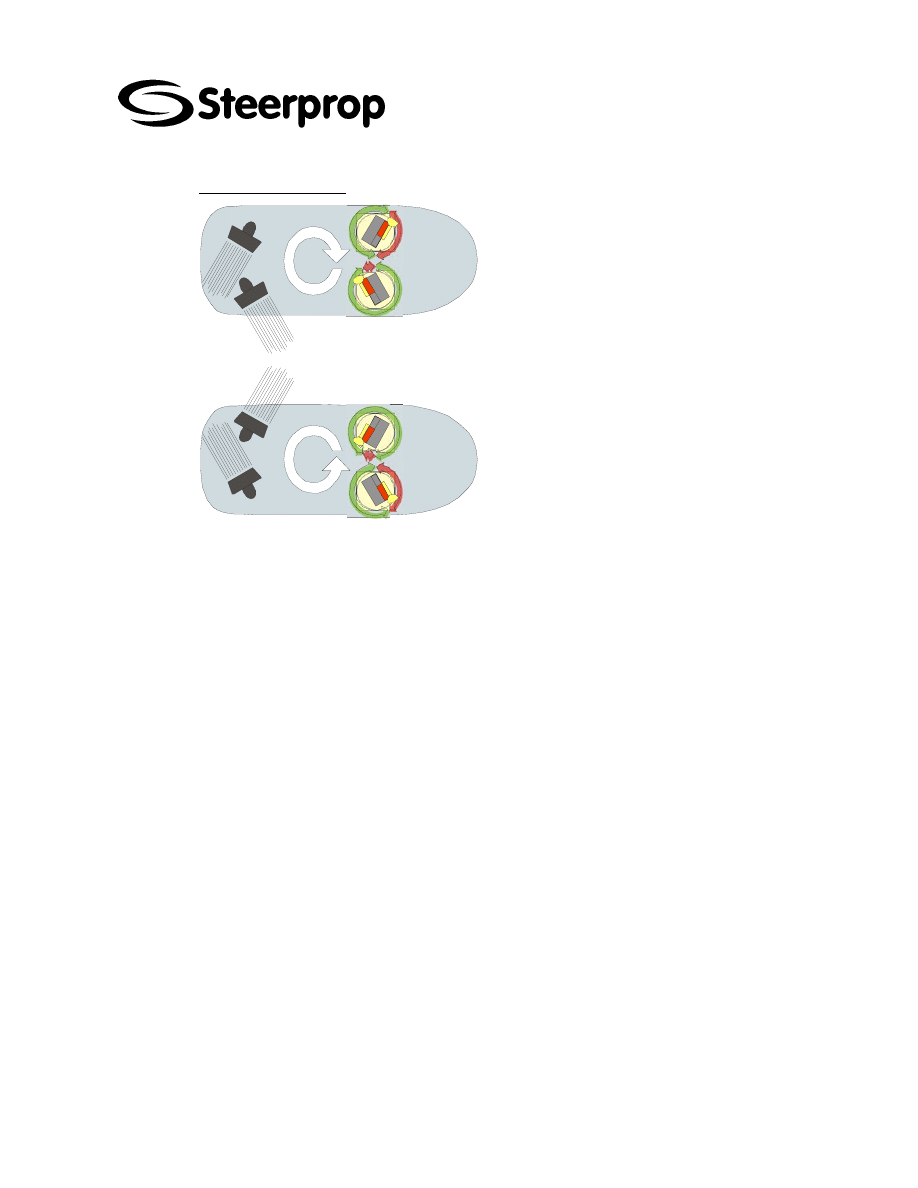
2.1.4. T
URNING ON SPOT
◊ STARBOARD TURN (CLOCKWISE)
Avoid the use of straight angles on the
propulsors, in order to avoid the wash
from one propulsor to hit the propeller
of the other.
Use propulsor angles as shown in the
figure.
◊ PORT TURN (COUNTER-
CLOCKWISE)
Avoid the use of straight angles on the
propulsors, in order to avoid the wash
from one propulsor to hit the propeller
of the other.
Use propulsor angles as shown in the
figure.
C102632-0 page 10 of 16
26.3.2007
© The information contained in this document is the sole property of Steerprop Ltd. any reproduction or disclosure in part or whole without written permission is prohibited.
DOC-1017-1
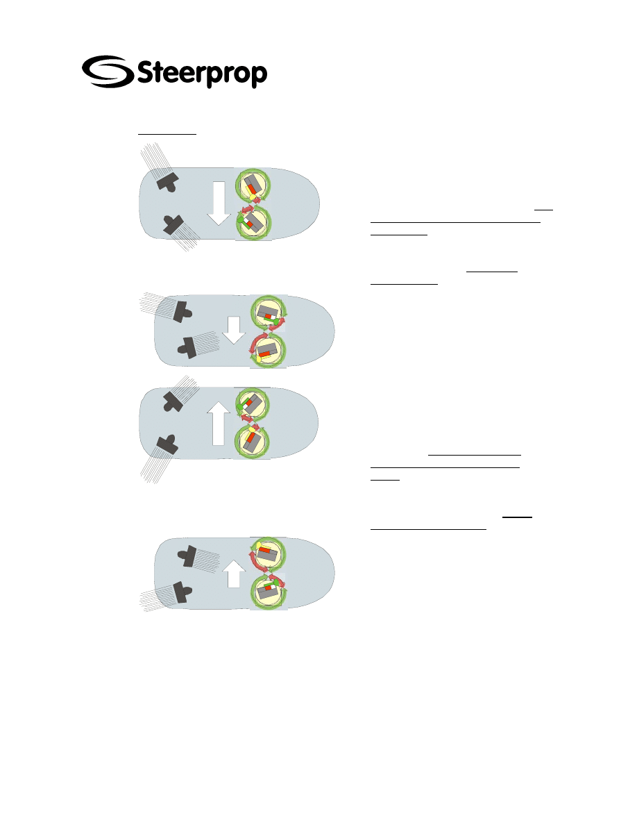
2.1.5. S
IDE STEP
◊ FAST SIDE STEP TO STARBOARD
Depending on hull form and vessel
length, the starboard propulsor should
be set at 40º ...45º astern and the port
propulsor at 20º ...30º ahead. The port
propulsor should be set with slightly
more power.
Fore/aft motion and yaw are controlled
by adjusting the power and turning
angle respectively - on the port
propulsor only!
◊ SLOW SIDE STEP TO STARBOARD
Not as useful as fast side step. Engine
power should be almost equal, with
only slightly more on the starboard
propulsor (to avoid forward motion)
◊ FAST SIDE STEP TO PORT
Depending on hull form and vessel
length, the port propulsor should be
set at 40º ...45º astern and the
starboard propulsor at 20º ...30º
ahead. The starboard propulsor
should be set with slightly more
power.
Fore / aft motion and yaw are
controlled by adjusting the power and
turning angle respectively - on the
starboard propulsor only!
◊ SLOW SIDE STEP TO PORT
Not as useful as fast side step. Engine
power should be almost equal, with
only slightly more on the port
propulsor (to avoid forward motion)
C102632-0 page 11 of 16
26.3.2007
© The information contained in this document is the sole property of Steerprop Ltd. any reproduction or disclosure in part or whole without written permission is prohibited.
DOC-1017-1
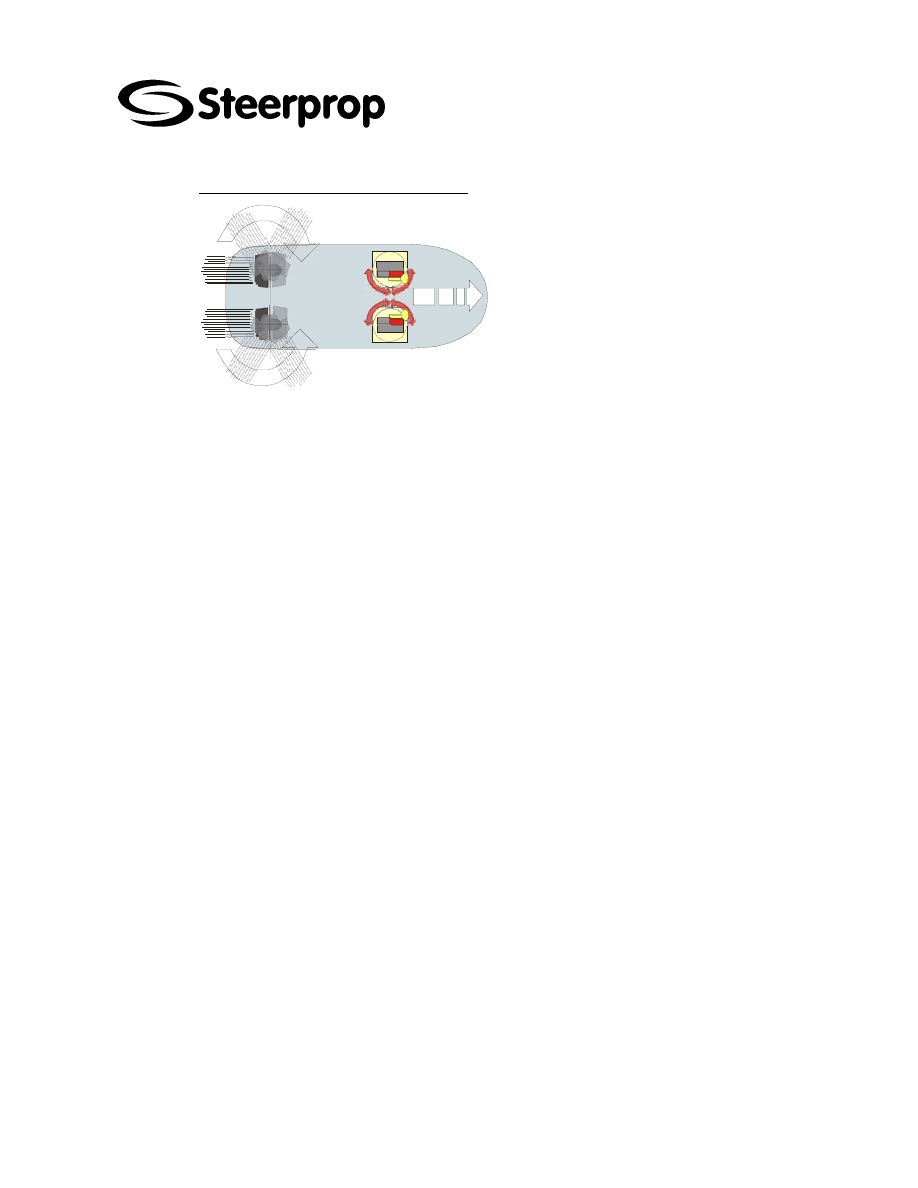
2.1.6. B
RAKING WITH TWO PROPULSORS
◊ CRASH STOP / BRAKING
Turn the propulsors through 180º; the
starboard propulsor counter-clockwise
and the port propulsor clockwise, i.e.
turn the control levers from ahead to
astern, via zero position.
Note: The braking starts already at
small turning angles and is very
efficient also at 90º; thus the stopping
is very efficient and fast - typically
within one ships length!
Note: During crash stop, the turning
speed of one of the propulsors may be
slower than the other due to
differences in torque. In such a case
the lever turning speed on the other
unit needs to be slowed down to find
identical turning angles / speeds.
Recommendation: During the turning
of the propulsors it is recommended
that the power of prime mover is
reduced to approximately 25 % to
minimize cavitation and vibration.
WARNING: THE BRAKING METHOD
SHOULD BE SELECTED ACCORDING
TO PRIME MOVER OR POWER
STATION TORQUE CAPACITY.
WARNING: THE PRIME MOVER OR
POWER STATION MAY STOP DURING
THIS OPERATION.
WARNING:
If
the
propulsors
are
under
an
external
control
system
eg.
autopilot,
the
Steerprop
control
levers
have
first
to
be
selected
active
before
starting
the
braking
/
crash
stop.
C102632-0 page 12 of 16
26.3.2007
© The information contained in this document is the sole property of Steerprop Ltd. any reproduction or disclosure in part or whole without written permission is prohibited.
DOC-1017-1
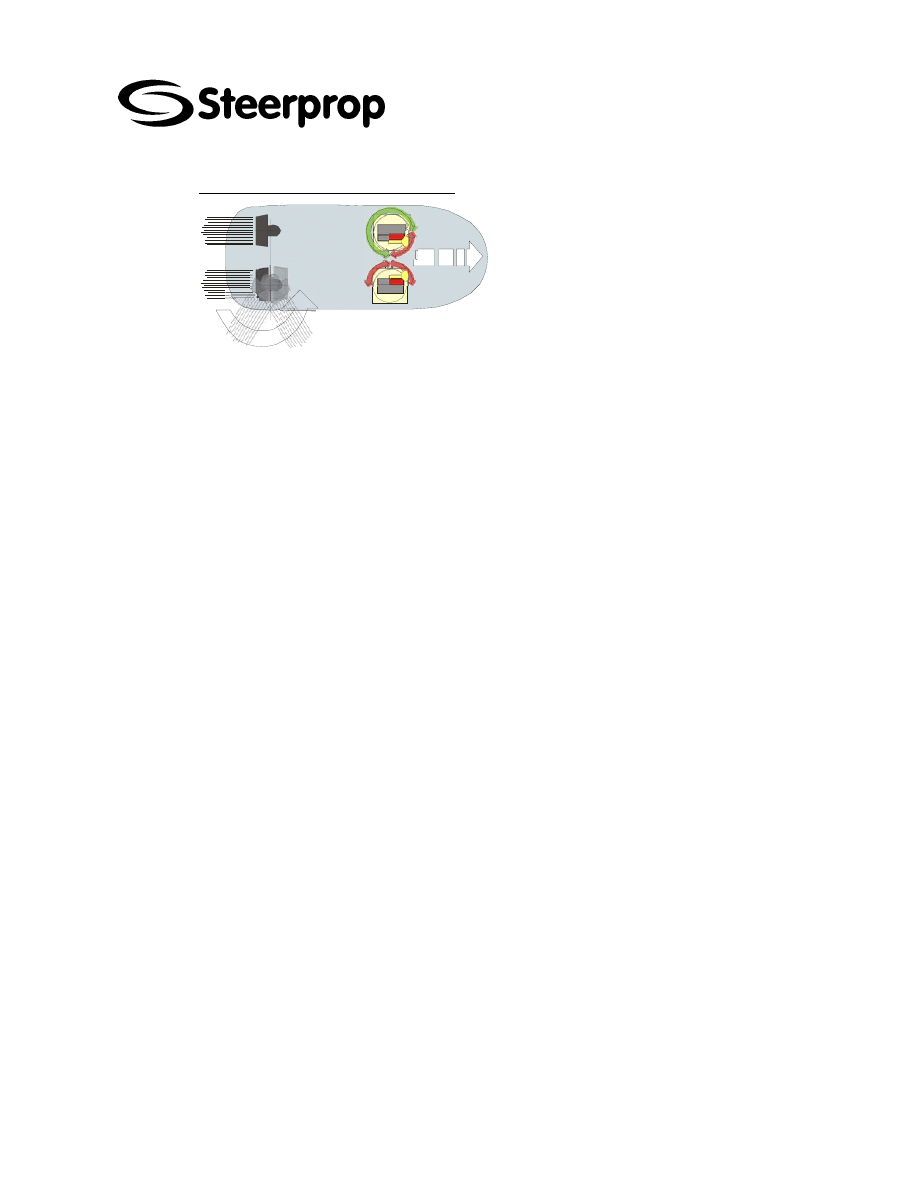
2.1.7. B
RAKING WITH ONE PROPULSOR
Turn the starboard or port propulsor
through 180º; the starboard propulsor
counter-clockwise or the port
propulsor clockwise, i.e. turn the
control levers from ahead to astern,
via zero position.
Recommendation: During the turning
of the propulsors it is recommended
that the power of prime mover is
reduced to approximately 25 % to
minimize cavitation and vibration. The
braking method with two propulsors
should always be primarily
considered.
WARNING: BRAKING METHOD
SHOULD BE SELECTED ACCORDING
TO PRIME MOVER OR POWER
STATION TORQUE CAPACITY.
WARNING:
The
prime
mover
or
power
station
may
stop
during
this
operation.

C102632-0 page 13 of 16
26.3.2007
© The information contained in this document is the sole property of Steerprop Ltd. any reproduction or disclosure in part or whole without written permission is prohibited.
DOC-1017-1
2.2. S
ERVICE AND DIAGNOSTIC FUNCTIONS AT ENGINE ROOM
DISPLAY
SED
2.2.1. I
NTELLIGENT SELF DIAGNOSTIC SYSTEM
(SDS)
The control system has as inbuilt an intelligent self diagnostic system which is
monitoring the operation condition of the control system, setting and feed-back
transmitters, and azimuth control speed.
The instructions are at service manual.

C102632-0 page 14 of 16
26.3.2007
© The information contained in this document is the sole property of Steerprop Ltd. any reproduction or disclosure in part or whole without written permission is prohibited.
DOC-1017-1
3. F
AILURE SITUATIONS
3.1. A
LARM INDICATIONS
3.1.1. S
ERVICE MANUAL
The individual system and component failure reasons and corrective actions are
described in the separate Steerprop Service Manual

C102632-0 page 15 of 16
26.3.2007
© The information contained in this document is the sole property of Steerprop Ltd. any reproduction or disclosure in part or whole without written permission is prohibited.
DOC-1017-1
4. E
MERGENCY OPERATION
4.1. L
OCAL CONTROL
,
STEERING
(S
TEERABLE PROPULSORS
)
The control system is equipped with local steering device, which is locating at
propulsor. The control is time-dependent.
4.1.1. L
OCAL CONTROL SELECTION
Local control selection switch SC01 is at the door of Steerprop Control Unit SCU. The
local control is selected, when the switch SC01 is at position “Local”
4.1.1.1. L
UBRICATION PUMP STARTING
When you use local control at starting situation, you should manually start the
lubrication pump at local push buttons.
4.1.2. S
TEERING
The steering control is time dependent with separate push buttons locating at SCU.
4.1.3. P
ROPULSOR ANGLE INDICATION
The propulsor is equipped with independent steering angle indication. The indication
system has a local mechanical indication and indication at SED.
Additional indications are through remote control system (not delivered by Steerprop)
4.1.4. R
EMOTE CONTROL SELECTION
Local / Remote control selection switch SC01 is at the door of Steerprop Control Unit
SCU. The remote control is selected, when the switch SC01 is at position “Remote”
4.2. P
ROPULSOR MECHANICAL TURNING
(S
TEERABLE
P
ROPULSOR
)
The steering motor equipped with brake has also means to turn the propulsor with
hand tool.
Using this possibility you should first disconnect motor fan and feedback transmitter.
When you install those back, you should carefully direct the transmitter according
service instructions and lock it with such kind of adhesive, which is possible to open at
maintenance.
4.2.1. D
ISC BRAKE OPEN
You can open the mechanical brake with a separate lever built on the brake.
4.2.2. T
URNING FROM MOTOR SHAFT END
You can turn the motor with wrench. Be careful, that you don’t damage the motor or its
auxiliaries.

C102632-0 page 16 of 16
26.3.2007
© The information contained in this document is the sole property of Steerprop Ltd. any reproduction or disclosure in part or whole without written permission is prohibited.
DOC-1017-1
5. P
ROPULSOR STOPPING
The system remote start/stop is through remote control system (not delivered by
Steerprop).
• The lubrication pump stops
• Control system transfer to stop status
Check before stopping, that ship and propulsion systems are allowed to stop.
Wyszukiwarka
Podobne podstrony:
C102633 A W0064 USE MAN
C102723 D W0064 CIR PART
C102140 G W0064 SCU2 CIR
C102012 F W0064 TGA Part4
P000827 C Eng General arrangement W0064
Edmond Hamilton Captain Future's Worlds of Tomorrow 17 Futuria
Edmond Hamilton Captain Future's Worlds of Tomorrow 05 Mars
Captain Dave's Survival Guide
C102012 F W0064 TGA Part6
C102139 B W0064 CAB DIA
Edmond Hamilton Captain Future's Worlds of Tomorrow 01 Jupiter
C102137 D W0064 SMU3 CIR
C102012 F W0064 TGA Part2
C102012 F W0064 TGA Part1
C102149 F W0064 CAB CON
C102722 B W0064 CON INST
więcej podobnych podstron