
Development
of Plot Plan

Basis of Site Selection
1.
Location
1.1 Area Allocation
1.2 Transport Facilities
1.3 Manpower availability
5.
Industrial Infrastructure
6.
Community Infrastructure
7.
Availability of Water
8.
Availability of Power
9.
Effluent Disposal
10. Availability of Industrial Gas
11. Site Size
12. Ecology
13. Pollution

Plot plan is master plan locating each unit/facility within
the plot boundary for process industry such as…
1.
Refinery
2.
Chemical /Agro Chemical / Petro Chemical / Organic
Chemical / Inorganic Chemical
3.
Fertilizer
4.
Pharmaceutical
5.
Metallurgical
6.
Power Generation

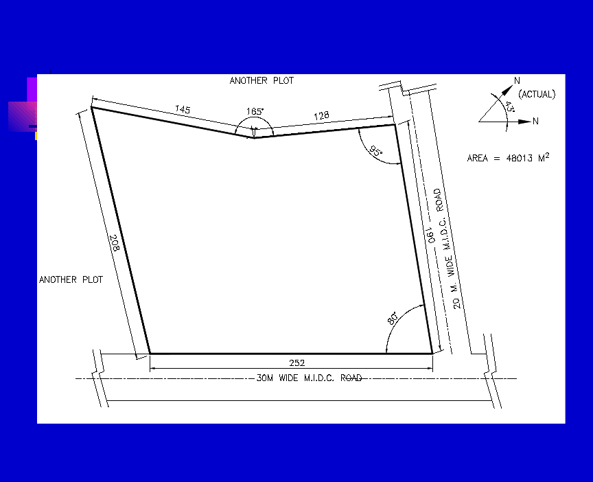
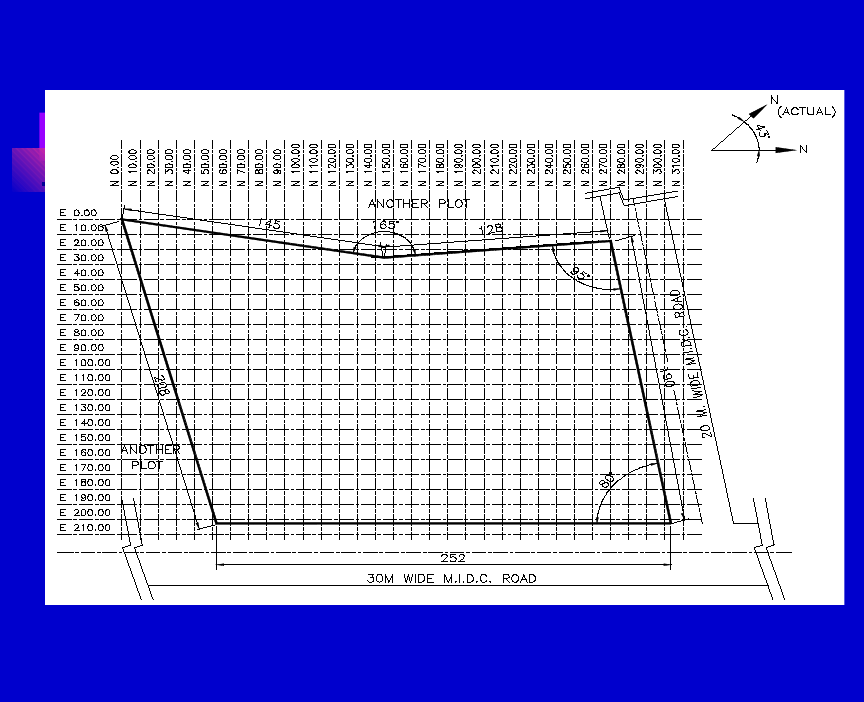
Data to be collected before starting
1.1 Civil
1.1.1. Plane table survey map.
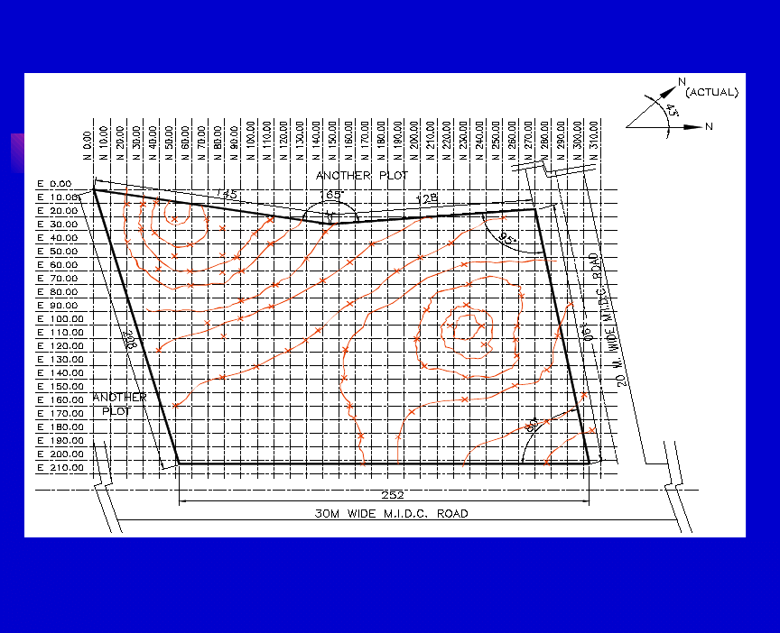
1.1.2. Contour survey map(at 10M grid).
1.1.3. Soil Bearing capacity.
1.1.4. Nature of Soil
1.1.5. Rail/Road Access.

Data to be collected before starting
1.2 Electrical
1.2.1. Location of Electric Supply Point.
1.2.2. Supply voltage levels.
1.2.3. Fault Levels.
1.2.4. Voltage Levels required within the unit.
1.2.5. Proposed distribution scheme.

1.3 Non Plant Facilities
Administrative Block
Canteen
Workshop
R&D, QC Lab and Pilot Plant
Gate House/Time office
Security Arrangements
Vehicle Parking
Medical Centre
Ware House
Covered Area
Open Area
Solid Warehouse
Liquid Warehouse
Steel / Scrap Yard
Fire Station
Weigh Bridge
Staff Colony

1.4 Meteorological Data
Minimum, Maximum and Normal Temperature during the
year
Rainfall
Intensity and Direction of the wind(wind rose)
Seismic zone
Wet and Dry Bulb temperatures
Flood level

1.5 Process Data
Size/Capacity of the process unit
Knowledge on the type of plant
Sequence of process flow
Hazardous nature of the plant
The Overall operating philosophy
Fully Automatic
Partially Automatic
Manual
Batch/Continuous
Raw material receipt and product dispatch philosophy
Storage Philosophy
Effluent plant capacity and discharge points, incirneration
requirements, etc.
Type of Hazard
No of flares

1.6 Data on Utilities
Source and/or supply point of raw water
Quality of Water available
Water Consumption for the process
Requirement of different types of utilities such as Steam, Air,
Nitrogen, DM water, Brine, etc.
Capacities and Grouping philosophy
Utility grouping philosophy

1.7 Statutory Requirements
State Industrial Development Corporation(SIDC)
Central / State Environmental Pollution Control Boards
(PCBS)
Factory Inspectorate
State Electricity Boards (SEB)
Chief Controller of Explosives (CCOE)
Static and Mobile Pressure Vessel Rules (SMPV)
Tariff Advisory Committee (TAC)
Aviation Laws
Chief Inspector of Boilers (CIB)
Oil Industry Safety Directorate (OISD)
Food and Drug Administration (FDA)
Ministry of Environment and Forest (MoEF)

1.8 Expansion Philosophy
Within the unit
Additional Units
Near future expansion
Far future expansion

Points to Note
Normally Construction is permitted on 50% of the plot area
with total built up area equal to area of the plot (i.e. F.S.I. = 1
(Depending upon the regulation governing the area and the
type of industry))
Area reserved for tree plantation shall be 1/3 of the area
occupied.
Water storage capacity - 24 hr. minimum.
Domestic water - 100 litres per person per day
Water requirement for Boiler - Steam rating x Working
factor
Cooling tower - 2% of capacity as drift and blow down
losses
Washing - 10-15 litres per day per sq.ft. of floor area of the
plant
Gardening - 5 litres per day per sq.ft. of garden area

Height of Boiler Chimney H (in m) = 14 Q
1/3
where Q is the
amount of
SO
2
generated in kg/hr.Inter unit distance based on the type and
nature of
the process.
Safety distances for the storages based on the relevant statutory
regulations.

Data to be generated before developing the
plot plan
2.1 Block dimensions of:
2.1.1 Process plants considering the expansion philosophy.
2.1.2 Utilities based on the grouping philosophy and
expansion requirements.
2.1.3 Electrical receiving station and sub-station.
2.1.4 Uncovered storage spaces.
2.1.5 Solid ware houses.
2.1.6 Non explosive chemical storages Explosive chemical
storages as per classification.
2.1.7 Petroleum Product as per classification.
2.1.8 Fire water storage requirements.
2.1.9 Acid / Alkali storage.
2.1.10 Steel and scrap yard.
2.1.11 Raw material storage and treatment facilities.

2.1.12 Contractor’s shed.
2.1.13 Effluent treatment & Incinerator plants.
2.1.14 Flare stacks.
2.1.15 Control room.
2.1.16 Administrative buildings, workshop, canteen,
laboratories, pilot plant etc.
2.2 Tentative details of pipe rack/sleepers.
2.3 Fire water storage requirements based on the hazard
classification.

Layout of liquid storage
Classification of Petroleum Products
* Class-A - Liquid which has flash point less than 23
deg cel.
* Class-B - Liquid which has flash point 23 deg cel. and
above below 65 deg cel.
* Class-C -Liquid which has flash point of 65 deg cel.
and above but below 93 deg cel.
* Excluded
Petroleum : Liquid which has flash point above 93 deg
cel.
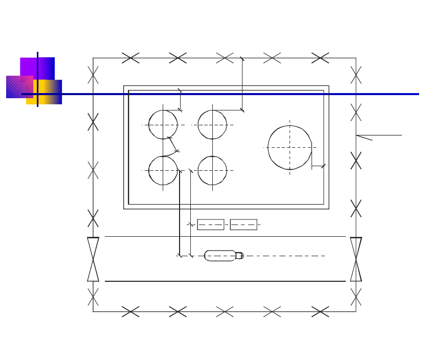
Fig.3: Equipment Layout - Explosive Tank farm

* Petroleum Class A - 30 litres in case of motor conveyance of
stationary engines, capacity of fuel tank.
* Petroleum Class B - 2,500 litres provided it is contained in a
receptacle not exceeding 1,000 liters capacity.
* Petroleum Class C - 45,000 litres
Regulatory quantity above which License
is necessary

Layout consideration for Explosive Tank
Form
Petroleum Storage tanks should be located in dyked enclosures
with roads all around the enclosures.
Dyked enclosure should be able to contain the complete
contents of the largest tank in the tank farm in case of an
emergency. Enclosure capacity shall be calculated after
deducting the volume of the tanks (other than the largest tank)
upto the height of enclosure. A free board of 200 mm shall be
considered in fixing the height of the dyke.
In case of excluded petroleum the capacity of the dyked
enclosure could be based on spill containment and not
containment on tank rupture.
The height of tank enclosure dyke shall be at least 1 M and
shall not be more than 2 M above average ground level inside.
However, for excluded petroleum it can be 600 mm.

Class A and/or Class B petroleum can be stored in the same dyked
enclosure.
When Class C is stored together, all safety stipulations applicable to Class
A
and Class B shall apply.
Excluded petroleum shall not be stored in the same dyke.
Tanks shall be arranged in two rows so that each tank is approachable
from
the surround road. The tank height shall not exceed one and a half times
the
diameter of tank or 20 M whichever is less.

Layout consideration for Explosive Tank
Form…
The tank height shall not exceed one and a half times
the diameter of tank or 20 M whichever is less.
Minimum distance between the tank shell and the
inside of the dyke wall shall not be less than one half
the height of the tank. Height is considered from
bottom to the top curb angle.
It is better that the corner of the bund should be
rounded and not at right angle as it is difficult
extinguish fire in a 90
0
angle corner because of the air
compression effect.

There should be a a minimum of two access points on
opposite sides of the bund to allow safe access/ escape in
all wind directions
Distances to be observed around facilities in an installation
shall be as per the relevant chart furnished in the
Petroleum Rules. (Refer Fig. 3 & relevant Table in the
Petroleum Rules).

Layout of Gas Storage
Storage Vessels are not allowed below ground level.They are
to be installed above ground level.
Vessels shall be located in open.
Vessels are not to be installed above one another.
If vessels in the installation are more than one, the
longitudinal axis of vessels should be parallel to each other.
Top surfaces of vessels are required to be made in one plane.
Vessels installed with their dished ends facing each other
shall have screen walls in between them.
The distances to be observed between two vessels in one
installation and distance from building or group of building or
line of adjoining property are given in Table 1 & Table 2.

The area where vessels, pumping equipment, loading and
unloading
facilities and direct fired vaporisers are provided shall be
enclosed by
an Industrial Type Fence at least 2 M high along the perimeter
of Safety
Zone.
The minimum distances to be observed around installation shall
be as per
the guidelines in SMPV which are reproduced in Table 1 and 2.

TABLE 1
Minimum Safety distances for flammable,
corrosive & toxic gases
Sl. No.
Water capacity of Vessels
( in litres )
Minimum distance
from Building or
Group of bldgs/line of
adjoining property
Minimum distance
between Pressure
Vessels
i
Not above 2000
5 metres
1 metre
ii
Above 2,000 but not
above 10,000
10 metres
1 metre
iii
Above 10,000 but not
above 20,000
15 metres
1.5 metres
iv
Above 20,000 but not
above 40,000
20 metres
2 metres
v
Above 40,000
30 metres
2 metres

TABLE 2
Minimum Safety distances for non-toxic gases
Sl. No.
Water capacity of Vessels
( in litres )
Minimum distance
from Building or
Group of bldgs/line
of adjoining
property
Minimum distance
between Pressure
Vessels
i
Not above 2000
3 metres
1 metre
ii
Above 2,000 but not
above 10,000
5 metres
1.5 metre
iii
Above 10,000 but not
above 20,000
10 metres
2 metres
iv
Above 20,000
15 metres
Diameter of larger
vessel
Note :
The distances specified above may be reduced by the Chief Controller in
cases where he is of the opinion that additional safety measures have been provided.

STEPS TO BE CONSIDERED WHILE
DEVELOPING THE PLOT PLAN
Study the contour map and establish the grade
levels/terraces.
Establish the N-S and E-W (or X-Y) grids, the
plant north in relation to geographical north.
Establish the free area along the plot boundary as
per the statutory norms.
Work out the area requirements for the green
belt, vehicle parking etc. as per the norms.
The process blocks shall be located in the
sequential order of process flow so that material
handling (solid/liquid) is minimum.

The blocks shall also be arranged considering
prevailing wind
direction so that flammable gases do not get carried
to sources of ignition.
Storage tanks shall be grouped according to
process classification.
Centralised control room shall be located in safe
area close to
process plant.

STEPS TO BE CONSIDERED WHILE
DEVELOPING THE PLOT PLAN
Two adjacent process units shall be located based on
annual shut down philosophy so that hot work shall not
affect the operation.
Process unit shall be located on higher ground away
from the unwanted traffic.
Process units shall be serviced by peripheral roads for
easy approach.
Utility block shall be kept at safe area close to process
plants.
Electrical sub-stations shall be placed at the load
centre to minimise cabling
Receiving station shall be placed near the supply
point.
Ware houses shall be located close to the material gate
to avoid truck traffic within the process area.

Flares, Furnaces/Heaters, cooling towers, etc. shall be
placed depending on the wind direction.
Provision of future expansion shall be considered.
Raw water storage shall be placed closer to water source.
Fire and raw water tanks shall be located together.

STEPS TO BE CONSIDERED WHILE
DEVELOPING THE PLOT PLAN
Fire stations shall be away from the hazardous area and
nearer to main gate.
Effluent treatment plant shall be located away from the
process and utility area on the downwind direction.
Workshop, contractor’s shed, storage yard, etc. shall
be at centralised location serviced by peripheral roads.
Two gates are preferred, one for the material entry
with weigh bridge and the other one for man entry.
Administrative block, laboratories, etc. shall be
located closer to the man entry gate.
Process unit can be separated within a fencing
providing additional gate.
Consider recommendation from the statutory
authorities for inter unit distances.
Residential colony shall be located away from the
plant more closer to the city limits.
********
Wyszukiwarka
Podobne podstrony:
Development of Carbon Nanotubes and Polymer Composites Therefrom
Development of BBM turbine
Development of financial markets in poland 1999
Development of a highthroughput yeast based assay for detection of metabolically activated genotoxin
01 [ABSTRACT] Development of poplar coppices in Central and Eastern Europe
Development of vertical bulb turbine
Development of organic agriculture in Poland, Technologie
Aristoteles # Guthrie (The Development of Aristotle's Theology 1) BB
Development of wind turbine control algorithms for industrial use
An experimental study on the development of a b type Stirling engine
PBO G 03 F01 Drill records of Contingency plan ships
DEVELOPMENT OF FACTORING MARKET IN TURKEY
Progressive development of sonographic features
Advanced Methods for Development of Wind turbine models for control designe
Development of Communist Theory
Development of Carbon Nanotubes and Polymer Composites Therefrom
Jung, Carl Gustav Volume 17 The Development of Personality
więcej podobnych podstron