Technical enquiries email: sales@murata-ps.com, tel: +508 339 3000
1
NEA/NEF10_6200850000_B01_21/04/08
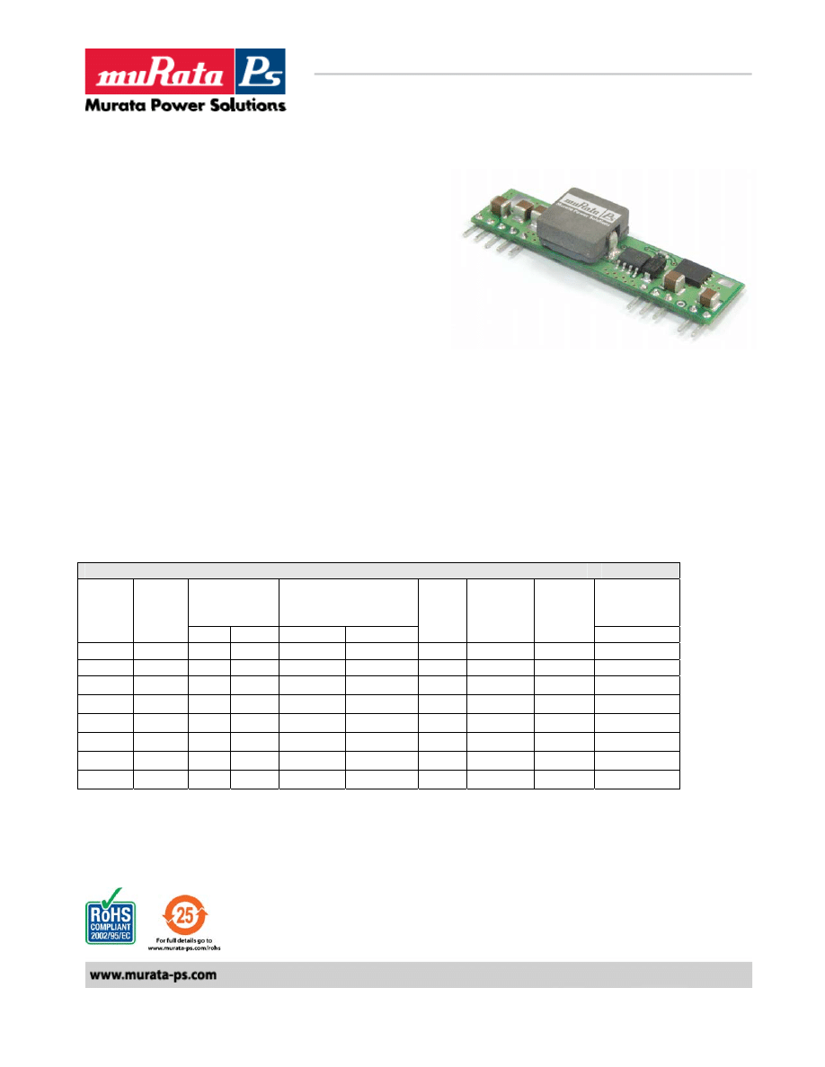
Volant NEA/NEF010 Series
Non-Isolated 10A SIP DC/DC Converters
Features:
9
Small size, minimal footprint/low profile
9
10A Output Current (all voltages)
9
High Efficiency: up to 95%
9
High reliability
9
RoHS Compliant
9
Cost efficient open frame design
9
Pre-bias monotonic start-up
9
+ve Enable Logic and –ve Enable Logic models available
Output
Input
Efficiency
PARD
(mVp-p)
Regulation
Max
Vin
Nom.
(V)
Range
(V)
Iin
TYP
(A)
Full Load
Vout
(V)
Iout
(A)
Typ. Max. Line
Load
Typ.
1.0
10
30
50
+/-0.2%
+/-0.5%
12
8.3 – 14
0.992
84%
1.2
10
30
50
+/-0.2%
+/-0.5%
12
8.3 – 14
1.163
86%
1.5
10
30
50
+/-0.2%
+/-0.5%
12
8.3 – 14
1.404
89%
1.8
10
30
50
+/-0.2%
+/-0.5%
12
8.3 – 14
1.666
90%
2.0
10
30
50
+/-0.2%
+/-0.5%
12
8.3 – 14
1.832
91%
2.5
10
30
50
+/-0.2%
+/-0.5%
12
8.3 – 14
2.264
92%
3.3
10
30
50
+/-0.2%
+/-0.5%
12
8.3 – 14
2.956
93%
5.0
10
30
50
+/-0.2%
+/-0.5%
12
8.3 – 14
4.385
95%
Murata Power Solutions
2
NEA/NEF10_6200850000_B01_21/04/08
Volant NEA/NEF010 Series
Non-Isolated 10A SIP DC/DC Converters
Input Characteristics
Notes & Conditions
Min
Typ.
Max
Units
Input Voltage Operating Range
8.3
12
14
Vdc
Input Reflected Ripple Current
200
mA p-p
Inrush Current Transient
0.2
A
2
s
Input Filter Type (external)
Low ESR
100
μF
Input Turn ON Threshold
8.5
V
Input Turn OFF Threshold
8.0
V
ON Control
Open Circuit or =Vin
OFF Control
<0.4VDC
Output Characteristics
Notes & Conditions
Min
Typ.
Max
Units
Vout Accuracy
100% load
-1.5
+1.5
%
Output Loading
0
10
A
Output Ripple & Noise
@ 20Mhz Bandwidth.
50
MVp-p
Maximum Capacitive Load
Low ESR
8000
μF
Vout Trim Range
-10
+10
%
Total Accuracy
Over line/load temperature
<2%
Current Limit
17
A
Output Line Regulation
-0.2
+0.2
%
Output Load Regulation
+0.5
-0.5
%
Turn-on Overshoot
1
%
SC Protection Technique
Hiccup with auto recovery
Pre-bias Start-up at output
Unit starts monotonically with pre-
bias
Dynamic Characteristics
Notes & Conditions
Min
Typ.
Max
Units
Load Transient
50% step, 0.1A/
μs
100 mV
Settling
Time
200
μs
Frequency
300
KHz
Rise Time
10% Vo to 90% Vo
3.5
ms
Start-Up Time
Vin to Vout and On/Off to Vout
Vout rise to monotonic
7 ms
General Specifications
Notes & Conditions
Min
Typ.
Max
Units
MTBF Calculated
(MIL-HDBK-217F)
1.0
x10
6
Hrs
Thermal Protection
Hotspot
110
°C
Operating Temperature
Without derating 100LFM
-40
60
°C
Operating Ambient Temperature
See Power derating curve
-40
85
°C
Dimensions 2”Lx0.327”Wx0.512”H
(50.8x8.3x13.0mm)
Pin Dimensions
0.025” (0.64mm) SQUARE
0.64
mm
Pin Material
Matte Sn Finish on component
Leads
Weight
10
g
Flammability Rating
UL94V-0
Standards Compliance
CSA C22.2, No.60950/UL 60950, Third Edition (2000), File UL E165113
Murata Power Solutions
3
NEA/NEF10_6200850000_B01_21/04/08
Volant NEA/NEF010 Series
Non-Isolated 10A SIP DC/DC Converters
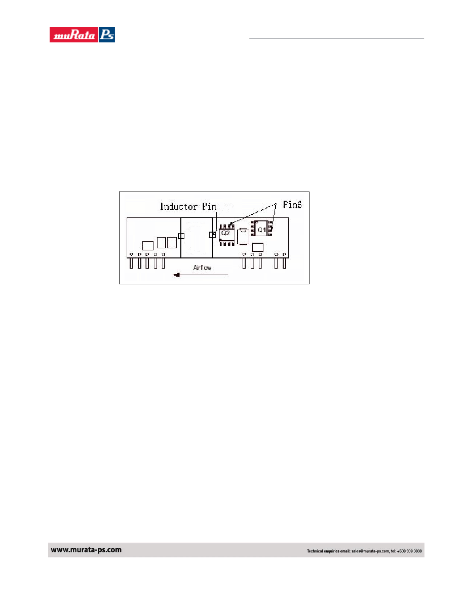
Thermal Considerations
The power module operates in a variety of thermal environments; however, sufficient cooling
should be provided to help ensure reliable operation of the unit. Heat is removed by
conduction, convection, and radiation to the surrounding environment. The thermal data
presented is based on measurements taken in a set-up as shown in fig 1. when the airflow is
parallel to the long axis of the module. The de-rating applies accordingly.
The temperature at either location should not exceed 110 °C. The output power of the module
should not exceed the rated power for the module (VO, set x IO, max)
.
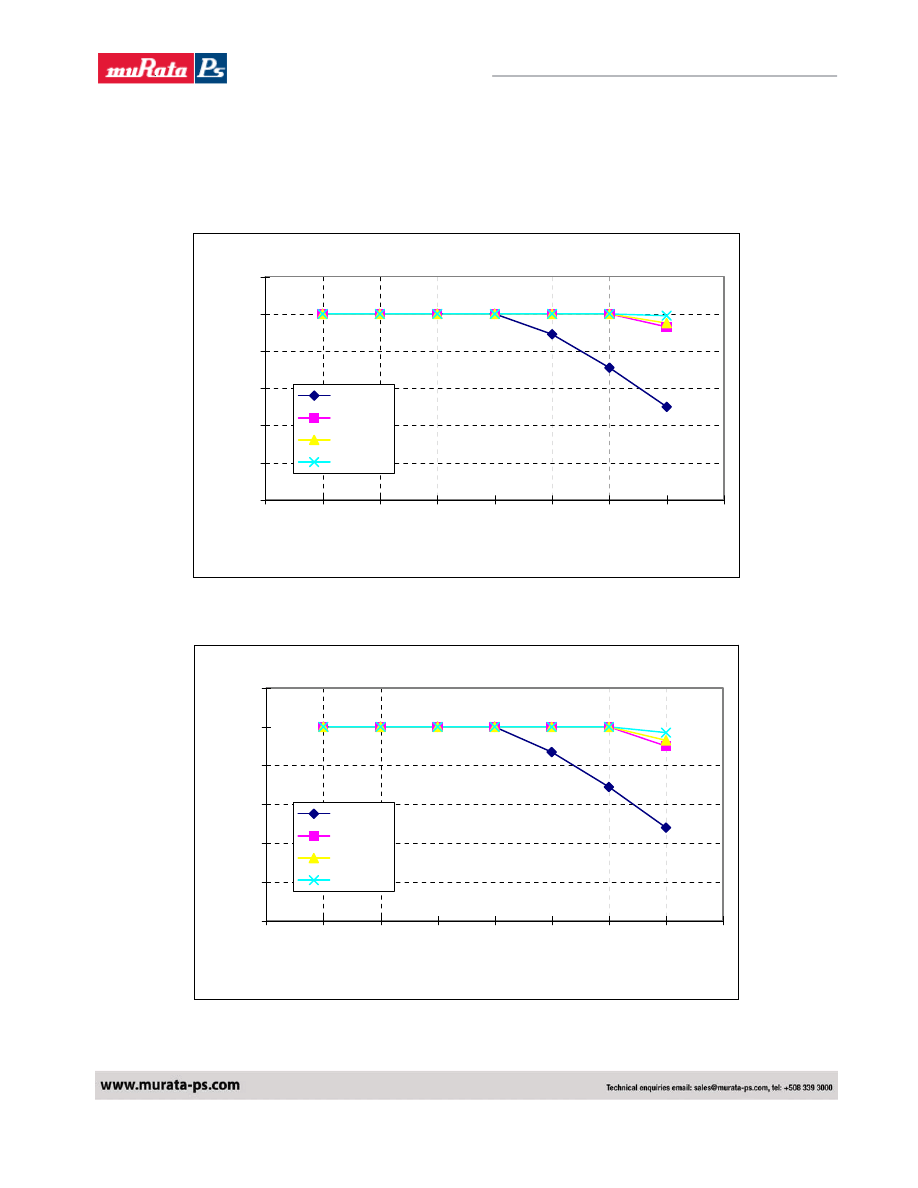
Convection Requirements for Cooling
To predict the approximate cooling needed for the module, refer to the Power Derating Curve in
Figure 2 to Figure 9.
These derating curve are approximations of the ambient temperature and airflow required to keep the
power module temperature below it's maximum rating. Once the module is assembled in the actual
system, the module's temperature should be verified.
Proper cooling can be verified by measuring the power module's temperature at Q1-pin 6 and Q2-pin
6 as shown in Figure 1.
Figure 1: Thermal Measurement Setup
Murata Power Solutions
4
NEA/NEF10_6200850000_B01_21/04/08
Volant NEA/NEF010 Series
Non-Isolated 10A SIP DC/DC Converters
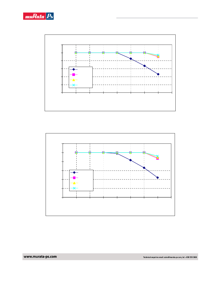
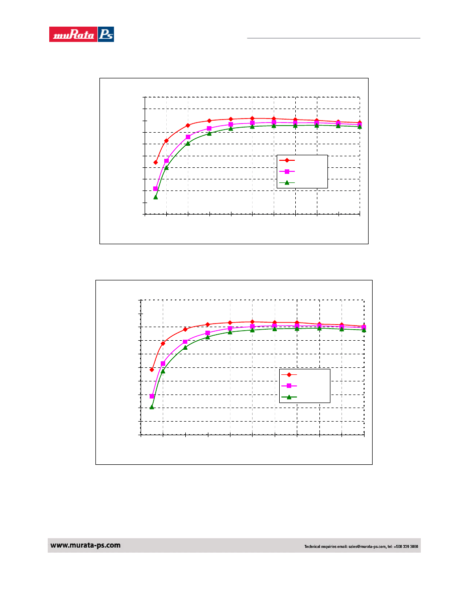
TYPICAL DERATING CURVES
NEF0100101B Derating Curve
0
2
4
6
8
10
12
20
30
40
50
60
70
80
90
100
Ambient Temperature (C)
Output Current (A)
0LFM
100LFM
200LFM
300LFM
Figure 2. Typical Power Derating vs Output Current for 12Vi and 1.0Vo
NEF0100121B Derating Curve
0
2
4
6
8
10
12
20
30
40
50
60
70
80
90
100
Ambient Temperature (C)
Output Current (A)
0LFM
100LFM
200LFM
300LFM
Figure 3. Typical Power Derating vs Output Current for 12Vi and 1.2Vo
Murata Power Solutions
5
NEA/NEF10_6200850000_B01_21/04/08
Volant NEA/NEF010 Series
Non-Isolated 10A SIP DC/DC Converters
NEF0100151B Derating Curve
0
2
4
6
8
10
12
20
30
40
50
60
70
80
90
100
Ambient Temperature (C)
Output Current (A)
0LFM
100LFM
200LFM
300LFM
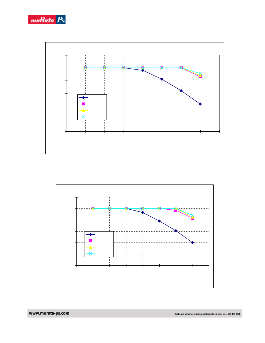
Figure 4. Typical Power Derating vs Output Current for 12Vi and 1.5Vo.
NEF0100181B Derating Curve
0
2
4
6
8
10
12
20
30
40
50
60
70
80
90
100
Ambient Temperature (C)
Output Current (A)
0LFM
100LFM
200LFM
300LFM
Figure 5. Typical Power Derating vs Output Current for 12Vi and 1.8Vo.
Murata Power Solutions
6
NEA/NEF10_6200850000_B01_21/04/08
Volant NEA/NEF010 Series
Non-Isolated 10A SIP DC/DC Converters
NEF0100201B Derating Curve
0
2
4
6
8
10
12
20
30
40
50
60
70
80
90
100
Ambient Temperature (C)
Output Current (A)
0LFM
100LFM
200LFM
300LFM
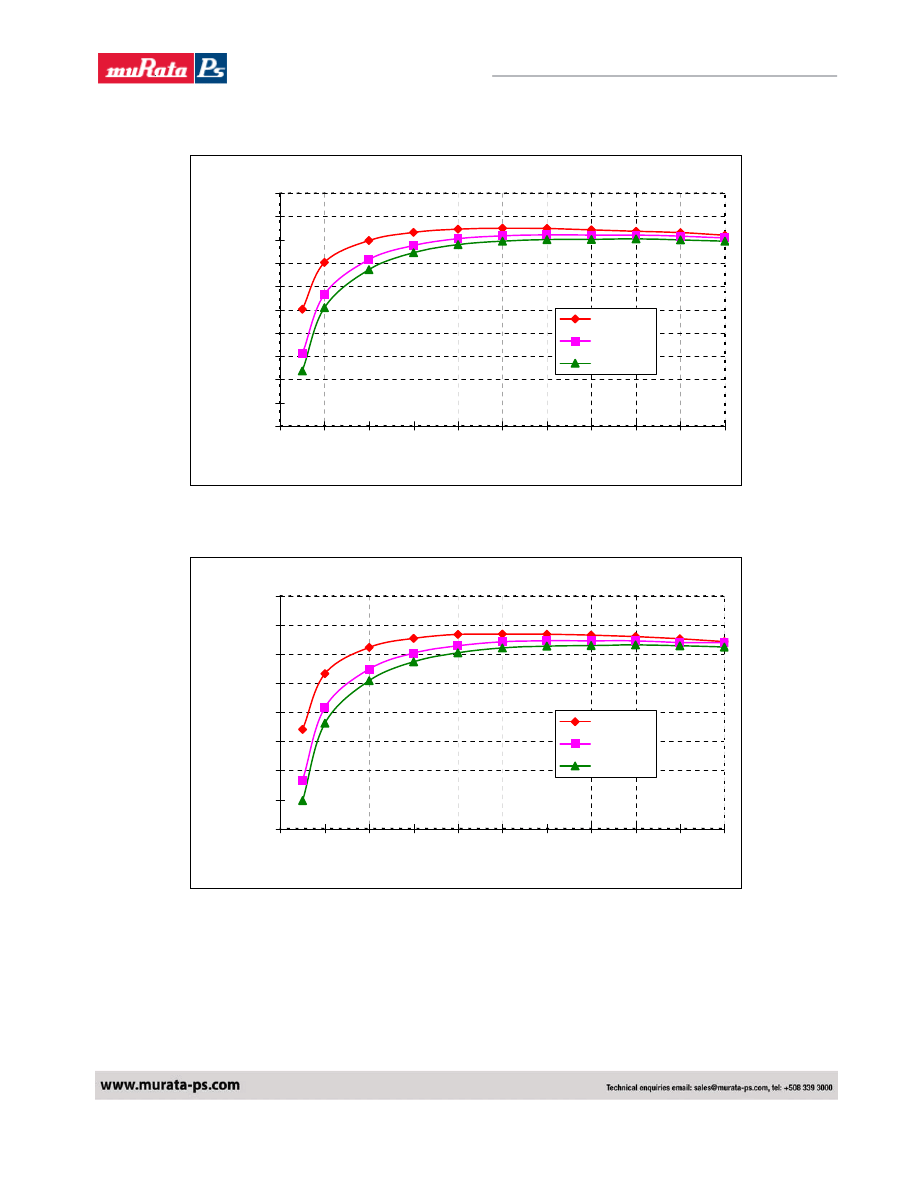
Figure 6. Typical Power Derating vs Output Current for 12Vi and 2.0Vo.
NEF0100251B Derating Curve
0
2
4
6
8
10
12
20
30
40
50
60
70
80
90
100
Ambient Temperature(C)
Output Current (A)
0LFM
100LFM
200LFM
300LFM
Figure 7. Typical Power Derating vs Output Current for 12Vi and 2.5Vo.
Murata Power Solutions
7
NEA/NEF10_6200850000_B01_21/04/08
Volant NEA/NEF010 Series
Non-Isolated 10A SIP DC/DC Converters
NEF0100331B Derating Curve
0
2
4
6
8
10
12
20
30
40
50
60
70
80
90
100
Ambient Temperature(C)
Output Current (A)
0LFM
100LFM
200LFM
300LFM
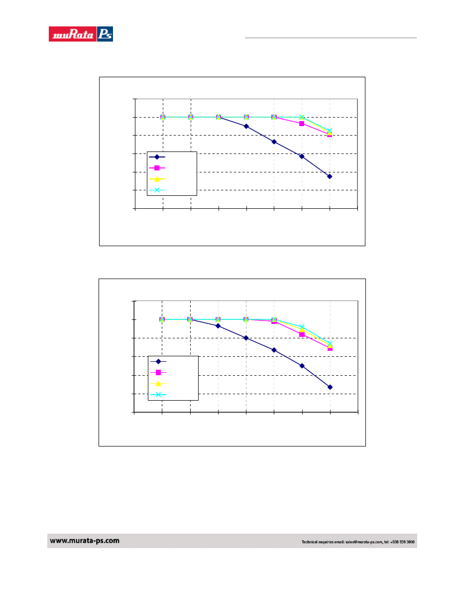
Figure 8. Typical Power Derating vs Output Current for 12Vi and 3.3Vo
NEF0100501B Derating Curve
0
2
4
6
8
10
12
20
30
40
50
60
70
80
90
100
Ambient Temperature(C)
Output Current (A)
0LFM
100LFM
200LFM
300LFM
Figure 9. Typical Power Derating vs Output Current for 12Vi and 5.0Vo
Murata Power Solutions
8
NEA/NEF10_6200850000_B01_21/04/08
Volant NEA/NEF010 Series
Non-Isolated 10A SIP DC/DC Converters
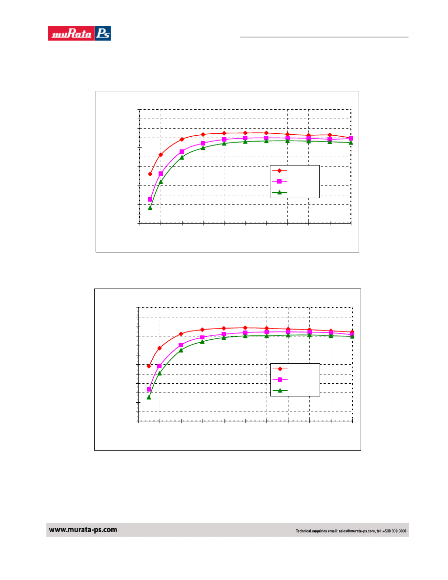
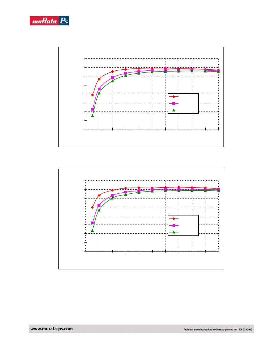
TYPICAL EFFICIENCY CURVES
NEF0100101B (Eff Vs Io)
40%
45%
50%
55%
60%
65%
70%
75%
80%
85%
90%
95%
100%
0
1
2
3
4
5
6
7
8
9
10
Current Load (A)
Efficiency (%)
Vin=9V
Vin=12V
Vin=14V
Figure 10. Efficiency Curves for Vout=1.0V (25C)
NEF0100121B (Eff Vs Io)
40%
45%
50%
55%
60%
65%
70%
75%
80%
85%
90%
95%
100%
0
1
2
3
4
5
6
7
8
9
10
Current Load (A)
Efficiency (%)
Vin=9V
Vin=12V
Vin=14V
Figure 11. Efficiency Curves for Vout=1.2V (25C)
Murata Power Solutions
9
NEA/NEF10_6200850000_B01_21/04/08
Volant NEA/NEF010 Series
Non-Isolated 10A SIP DC/DC Converters
NEF0100151B (Eff Vs Io)
50%
55%
60%
65%
70%
75%
80%
85%
90%
95%
100%
0
1
2
3
4
5
6
7
8
9
10
Current Load (A)
Efficiency (%)
Vin=9V
Vin=12V
Vin=14V
Figure 12. Efficiency Curves for Vout=1.5V (25C)
NEF0100181B (Eff Vs Io)
50%
55%
60%
65%
70%
75%
80%
85%
90%
95%
100%
0
1
2
3
4
5
6
7
8
9
10
Current Load (A)
Efficiency (%)
Vin=9V
Vin=12V
Vin=14V
Figure 13. Efficiency Curves for Vout=1.8V (25C)
Murata Power Solutions
10
NEA/NEF10_6200850000_B01_21/04/08
Volant NEA/NEF010 Series
Non-Isolated 10A SIP DC/DC Converters
NEF0100201B (Eff Vs Io)
50%
55%
60%
65%
70%
75%
80%
85%
90%
95%
100%
0
1
2
3
4
5
6
7
8
9
10
Current Load (A)
Efficiency (%)
Vin=9V
Vin=12V
Vin=14V
Figure 14. Efficiency Curves for Vout=2.0V (25C)
NEF0100251B (Eff Vs Io)
60%
65%
70%
75%
80%
85%
90%
95%
100%
0
1
2
3
4
5
6
7
8
9
10
Current Load (A)
Efficiency (%)
Vin=9V
Vin=12V
Vin=14V
Figure 15. Efficiency Curves for Vout=2.5V (25C)
Murata Power Solutions
11
NEA/NEF10_6200850000_B01_21/04/08
Volant NEA/NEF010 Series
Non-Isolated 10A SIP DC/DC Converters
NEF0100331B (Eff Vs Io)
60%
65%
70%
75%
80%
85%
90%
95%
100%
0
1
2
3
4
5
6
7
8
9
10
Current Load (A)
Efficiency (%)
Vin=9V
Vin=12V
Vin=14V
Figure 16. Efficiency Curves for Vout=3.3V (25C)
NEF0100501B (Eff Vs Io)
60%
65%
70%
75%
80%
85%
90%
95%
100%
0
1
2
3
4
5
6
7
8
9
10
Current Load (A)
Efficiency (%)
Vin=9V
Vin=12V
Vin=14V
Figure 17. Efficiency Curves for Vout=5.0V (25C)
Murata Power Solutions
12
NEA/NEF10_6200850000_B01_21/04/08
Volant NEA/NEF010 Series
Non-Isolated 10A SIP DC/DC Converters
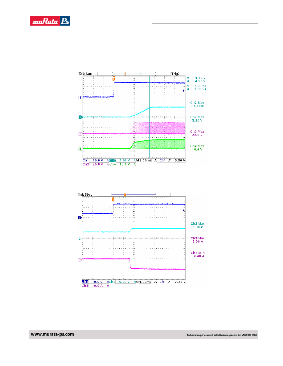
Typical Start Up
Ch1 : Vin
Ch2 : Vout
Ch3.: Top Fet Vg
Ch4 : Bottom Fet Vg
Typical Start Up with pre-bias
Ch1 : Vin
Ch2 : Vout
Ch3 : Output Current
Murata Power Solutions
13
NEA/NEF10_6200850000_B01_21/04/08
Volant NEA/NEF010 Series
Non-Isolated 10A SIP DC/DC Converters
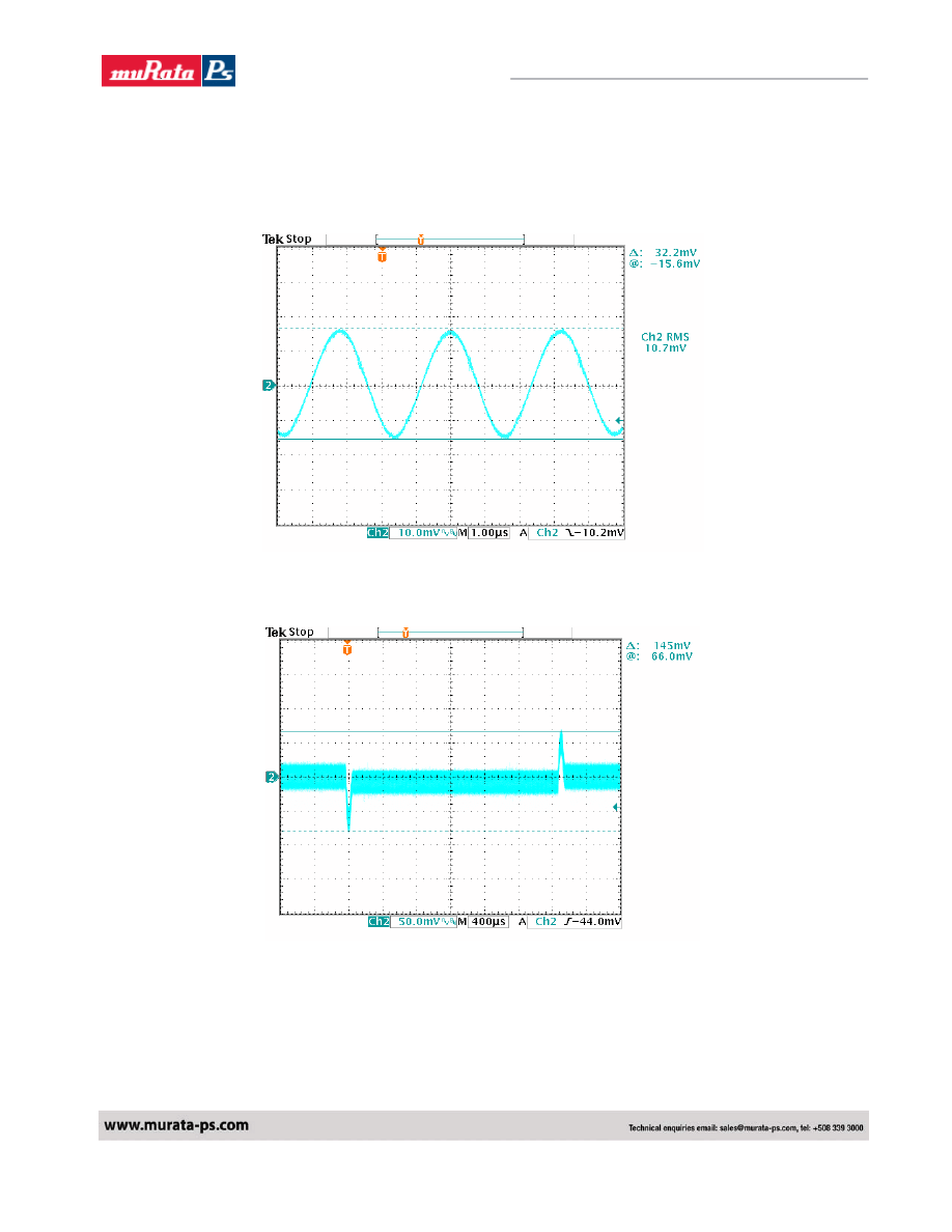
Typical Output Noise and Ripple
Vin = 12Vdc , Vo=5.0V/10A
Output with 1uF ceramic and 10uF tantalum capacitor
Typical Output Transient Response
Vin = 12Vdc , Vo=5.0V , 50% - 100% - 50% Load change , @0.1A/uS

Murata Power Solutions
14
NEA/NEF10_6200850000_B01_21/04/08
Volant NEA/NEF010 Series
Non-Isolated 10A SIP DC/DC Converters
Output Voltage Set point adjustment.
The following relationship establish the calculation of external resistors for the NEF series:
Trim-Up
For trim_Up an external resistor is connected between the TRIM and Ground Pin.
)
(K
)
7
.
0
1
(
,
Ω
−
−
×
=
−
Rt
V
Vo
R
R
nom
o
up
trim
Where,
Rt = 1 KΩ
R1 = 15 K
Ω
Vo,nom is the nominal output voltage
Vo is the desired output voltage
Trim_Down
For trim down an external resistor is to be connected between TRIM and Vout pins of the module.
The value of Rtrim_Down is calculated from the following relationship.
)
(K
)
7
.
0
(
1
,
Ω
−
−
−
×
=
−
Rt
Vo
V
Vo
R
R
nom
o
down
trim
The values of R1 , Rt , Vo,num , Vo are as defined above.
Examples:
Vout = 1.5V Trim_Up required 8% to 1.62V
Vo – Vo,nom = 1.62 – 1.5 = 0.12V
)
(K
5
.
86
1
12
.
0
7
.
0
15
Ω
=
−
×
=
− up
trim
R
Vout = 1.5V Trim_Down required 8% to 1.38V
Vo,nom - Vo = 1.5 – 1.38 = 0.12V
)
(K
84
1
12
.
0
)
7
.
0
38
.
1
(
15
Ω
=
−
−
×
=
− down
trim
R
Murata Power Solutions
15
NEA/NEF10_6200850000_B01_21/04/08
Volant NEA/NEF010 Series
Non-Isolated 10A SIP DC/DC Converters
The following relationship establish the calculation of external resistors for the NEA series:
)
(K
1
)
7525
.
0
7
.
0
15
(
Ω
−
−
×
=
Vo
R
adj
For Vout setting an external resistor is connected between the TRIM and Ground Pin.
Resistor values for different output voltages are calculated as given in the table:
Vo, set (Volts)
RAdj (K
Ω)
0.75 Open
1.2 22.46
1.5 13.05
1.8 9.024
2.0 7.417
2.5 5.009
3.3 3.122
5.0 1.472
Remote Sense:
All Murata Power Solutions SIP power modules offer an option for remote sense. The remote sense
compensates for any distribution drops to accurately control voltage at the point of load. The voltage between
the sense
pin to Vout pin should not exceed 0.5V.
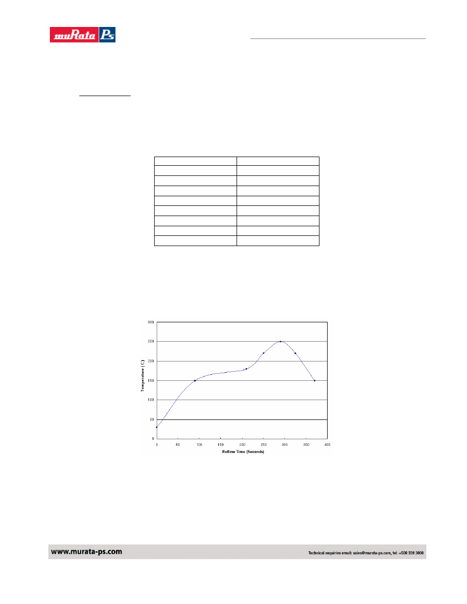
SMT Lead free Reflow profile
1. Ramp up rate during preheat : 1.33
℃/Sec ( From 30℃ to 150℃ )
2. Soaking temperature : 0.29
℃/Sec ( From 150℃ to 180℃ )
3. Ramp up rate during reflow : 0.8
℃/Sec ( From 220℃ to 250℃ )
4. Peak temperature : 250
℃, above 220℃ 40 to 70 Seconds
5.
Ramp up rate during cooling : -1.56
℃/Sec ( From 220℃ to 150℃ )
Murata Power Solutions
16
NEA/NEF10_6200850000_B01_21/04/08
Volant NEA/NEF010 Series
Non-Isolated 10A SIP DC/DC Converters
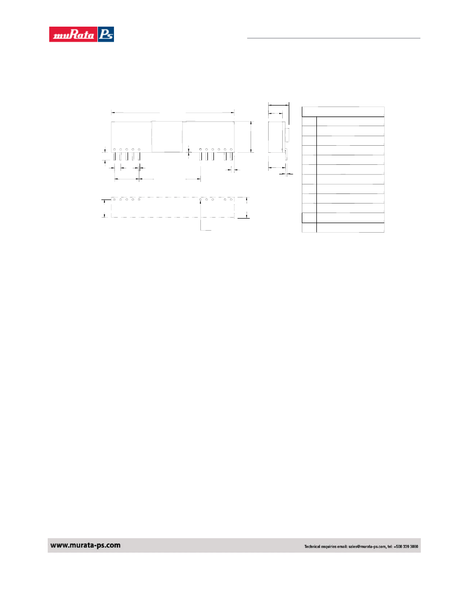
Mechanical Information
PIN CONNECTION
FUNCTION
+Output
+Output
+Sense
+Output
Common
Common
Pin
1
2
3
4
5
6
All Dimmension In Inches(mm)
Tolerance :
.XX=
0.02 ( .X=0.5 )
.XXX=
0.010 ( .XX=0.25 )
7
8
9
10
11
+V Input
+V Input
No Pin
Trim
On/Off Control
LAYOUT PATTERN
TOP VIEW
0.33(8.4)
0.29(7.4)
1.1mm PLATED THROUGH HOLE
1.6mm PAD SIZE
0.025(0.64)
1.000(25.40)
2.00(50.8)
5
4
3
2
1
0.14(3.6)
0.100(2.54)
0.400(10.20)
SIZE SIP
0.50(12.70)
11
10
9
8
7
6
0.050(1.30)
0.010(0.25)
min.
0.28(7.1)
0.025(0.64)
0.23(5.8)
0.327(8.30)max.
Safety Considerations
The NEA/NEF series of converters are certified to IEC/EN/CSA/UL 60950. If this product is built into information
technology equipment, the installation must comply with the above standard. An external input fuse (no more than 20
Amps, recommended) must be used to meet the above requirements. The output of the converter [Vo(+)/Vo(-)] is
considered to remain within SELV limits when the input to the converter meets SELV or TNV-2 requirements.
The converters and materials meet UL 94V-0 flammability ratings.
Murata Power Solutions
17
NEA/NEF10_6200850000_B01_21/04/08
Volant NEA/NEF010 Series
Non-Isolated 10A SIP DC/DC Converters
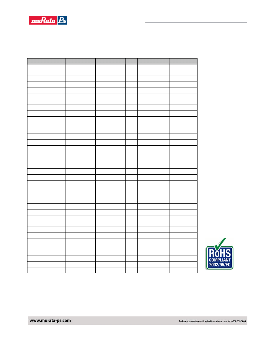
Ordering Information
Note: SMT versions are also available. See applicable datasheet for details.
Part Number
Vin
Vout
Iout Enable Logic
Pin Length
NEF0100101B0C 8.3V - 14.0V
1.0V 10A Positive 0.139"
NEF0100121B0C 8.3V - 14.0V
1.2V 10A Positive 0.139"
NEF0100151B0C 8.3V - 14.0V
1.5V 10A Positive 0.139"
NEF0100181B0C 8.3V - 14.0V
1.8V 10A Positive 0.139"
NEF0100201B0C 8.3V - 14.0V
2.0V 10A Positive 0.139"
NEF0100251B0C 8.3V - 14.0V
2.5V 10A Positive 0.139"
NEF0100331B0C 8.3V - 14.0V
3.3V 10A Positive 0.139"
NEF0100501B0C 8.3V - 14.0V
5.0V 10A Positive 0.139"
NEF0100101S0C 8.3V - 14.0V
1.0V
10A
Positive
SMT
NEF0100121S0C 8.3V - 14.0V
1.2V
10A
Positive
SMT
NEF0100151S0C 8.3V - 14.0V
1.5V
10A
Positive
SMT
NEF0100181S0C 8.3V - 14.0V
1.8V
10A
Positive
SMT
NEF0100201S0C 8.3V - 14.0V
2.0V
10A
Positive
SMT
NEF0100251S0C 8.3V - 14.0V
2.5V
10A
Positive
SMT
NEF0100331S0C 8.3V - 14.0V
3.3V
10A
Positive
SMT
NEF0100501S0C 8.3V - 14.0V
5.0V
10A
Positive
SMT
NEF0100100B0C 8.3V - 14.0V
1.0V 10A Negative 0.139"
NEF0100120B0C 8.3V - 14.0V
1.2V 10A Negative 0.139"
NEF0100150B0C 8.3V - 14.0V
1.5V 10A Negative 0.139"
NEF0100180B0C 8.3V - 14.0V
1.8V 10A Negative 0.139"
NEF0100200B0C 8.3V - 14.0V
2.0V 10A Negative 0.139"
NEF0100250B0C 8.3V - 14.0V
2.5V 10A Negative 0.139"
NEF0100330B0C 8.3V - 14.0V
3.3V 10A Negative 0.139"
NEF0100500B0C 8.3V - 14.0V
5.0V 10A Negative 0.139"
NEF0100100S0C 8.3V - 14.0V
1.0V
10A
Negative
SMT
NEF0100120S0C 8.3V - 14.0V
1.2V
10A
Negative
SMT
NEF0100150S0C 8.3V - 14.0V
1.5V
10A
Negative
SMT
NEF0100180S0C 8.3V - 14.0V
1.8V
10A
Negative
SMT
NEF0100200S0C 8.3V - 14.0V
2.0V
10A
Negative
SMT
NEF0100250S0C 8.3V - 14.0V
2.5V
10A
Negative
SMT
NEF0100330S0C 8.3V - 14.0V
3.3V
10A
Negative
SMT
NEF0100500S0C 8.3V - 14.0V
5.0V
10A
Negative
SMT
NEA0101500B0C 8.3V - 14.0V
0.75V – 5.0V 10A
Negative
0.139"
NEA0101500S0C 8.3V - 14.0V
0.75V – 5.0V 10A
Negative
SMT
NEA0101501B0C 8.3V - 14.0V
0.75V – 5.0V 10A
Positive
0.139"
NEA0101501S0C 8.3V - 14.0V
0.75V – 5.0V 10A
Positive
SMT
Murata Power Solutions
18
NEA/NEF10_6200850000_B01_21/04/08
Volant NEA/NEF010 Series
Non-Isolated 10A SIP DC/DC Converters
Label Information
Pin Length Option
B=0.139”
S=SMT
Enable Logic, 0 for
–ve, 1 for +ve
Vout
Iout
Place Holder
Vout Range
F=Fixed
A=Adjustable
Vin (value or range)
C= 3.3V -5.0V
E= 8.3V -14V
F= 6.0V -14V
Non-Isolated Family
0 = Standard. (No PGood option)
P = Power Good Option
C = RoHS Compliant
N E A 0 1 0 x x x 0 B 0 –
X
C
X = Factory control character
(not required when ordering)
RoHS Compliant
The NEA/NEF010 series of converters is in compliance with the European Union Directive 2002/95/EC (RoHS) with repsect to the following
sustances: lead (Pb), mercury (Hg), cadmium (Cd), hexavalent chromium, polybrominated biphenyls (PBB) or polybrominated diphenyl ethers
(PBDE).
Wyszukiwarka
Podobne podstrony:
cdc nea nef010 smt
Fotogrametria i SIP cwiczenia 3
9,10 Modele rastrowych i wektorowych danych w SIP,Mozliwosci wykorzystania SIP w architekturze krajo
Aiwa CDC R136 (2)
SIP-autostrada, gik VI sem, GiK VI, SIP, przodki SIP, SIP 3
pierwsze kolo sip
cdc qus20 120
CDC PL
Lasy SIP 2015 wyklad1
SIP GiK 15 pytania
SIP wykład test zaliczenie
Fotogrametria i SIP wyklad 1 2 3 konspekt
sip 2
H323 SIP
sciaga SIP do wydruku, Geodezja, SIP
więcej podobnych podstron