
ELECTRONIC ENGINEERING LTD
.
Runner Series
W
IRELESS AND
W
IRED
C
ONTROL
P
ANEL
Installation and
Configuration Guide
by CROW Electronic Engineering Ltd.
Version 9.08.2

IMPORTANT NOTICE
All information and data contained in this document is proprietary and confidential.
CROW Electronic Engineering Ltd. shall not be liable, in any event, for any claims for damages or
any other remedy in any jurisdiction whatsoever, whether in an action in contract, tort (including
negligence and strict liability) or any other theory of liability, whether in law or equity including,
without limitation, claims for damages or any other remedy in whatever jurisdiction, and shall not
assume responsibility for patent infringements or other rights to third parties, arising out of or in
connection with this document. Further, CROW Electronic Engineering Ltd. reserves the right to
revise this publication and to make changes to its content, at any time, without obligation to notify
any person or entity of such revision changes. These materials are copyrighted and any
unauthorized use of these materials may violate copyright, trademark, and other laws. Therefore,
no part of this publication may be reproduced, photocopied, stored on a retrieval system, or
transmitted without the express written consent of CROW Electronic Engineering Ltd. Any new
issue of this document invalidates previous issues.
©CROW Electronic Engineering Ltd. 2005, 2006. All rights reserved.
Information in this document is subject to change without notice. No part of this document
may be reproduced or transmitted in any form or by any means, electronic or mechanical,
without express written permission of CROW Electronic Engineering Ltd..
Document Version 1.00.015
Runner Series
P/N 7103585 Rev. C. Y.A/Y.S
January 2008

i
CONTENTS
OVERVIEW ........................................................................................................................... 6
C
ONNECTION
D
IAGRAMS
......................................................................................................... 6
RUNNER IN MINI BOX SPECIFICATION :............................................................................ 7
RUNNER COMPACT /FDX SPECIFICATION :........................................................................ 9
INPUT OPTIONS ................................................................................................................ 11
D
IFFERENT
I
NPUT
C
ONFIGURATIONS
........................................................................................ 11
Z
ONE
W
IRING
E
XAMPLES
...................................................................................................... 12
O
THER
I
NPUTS
.................................................................................................................. 14
OUTPUTS............................................................................................................................ 16
D
ESCRIPTION OF
O
UTPUTS
.................................................................................................... 16
K
EYPAD
P
ORT
.................................................................................................................... 16
E
XPANSION
P
ORT
............................................................................................................... 17
ACCESSORIES .................................................................................................................... 18
R
ADIO
R
ECEIVER
................................................................................................................ 18
V
OICE
B
OARD
.................................................................................................................... 18
N
IGHT
M
ONITOR
K
EYPAD
..................................................................................................... 25
KEYPAD INDICATORS........................................................................................................ 27
LED
K
EYPAD
..................................................................................................................... 27
LCD
KEYPAD................................................................................................................... 32
KEYPAD ADDRESS ASSIGNMENT & INSTALLATION.......................................................... 34
LED
K
EYPAD
..................................................................................................................... 34
LCD
KEYPAD................................................................................................................... 35
A
DJUSTING
B
ACKLIGHTING AND
B
UZZER
T
ONE
............................................................................ 36
LCD KEYPAD “LOCAL EDIT” MODE .................................................................................... 37
LCD
K
EYPAD
..................................................................................................................... 37
PROGRAM MODE ACCESS .................................................................................................. 44
A
CCESSING
P
ROGRAM
M
ODE
.................................................................................................. 44
E
XITING
P
ROGRAM
M
ODE
..................................................................................................... 45
SPECIAL KEYPAD FUNCTIONS........................................................................................... 55
A
RMING OR
D
ISARMING
T
WO
A
REAS AT A
K
EYPAD
....................................................................... 55
LCD
Q
UICK
V
IEW
M
ODE
...................................................................................................... 55

RUNNER - Installation & Config. Guide
CONTENTS
ii
T
OGGLE
C
HIME
M
ODE
O
N
/O
FF
.............................................................................................. 56
S
END
M
ANUAL
T
EST
C
ALL
..................................................................................................... 56
M
ANUALLY
A
NSWER AN
I
NCOMING
C
ALL
.................................................................................... 56
PROGRAMMING USERS ..................................................................................................... 57
U
SER
C
ODES
..................................................................................................................... 57
U
SER
C
ODE
T
YPE
............................................................................................................... 58
U
SER
A
REAS
..................................................................................................................... 58
U
SER
A
CCESS
O
PTIONS
........................................................................................................ 59
U
SER
C
ODE
P
RIVILEGES
-
USER PROGRAM OPTIONS
..................................................................... 60
R
ADIO
U
SER
T
YPE
-
PENDANT TYPE
......................................................................................... 60
R
ADIO
U
SER
P
RIVILEGES
–
PENDANT OPTIONS
............................................................................ 61
U
SER
T
IME
Z
ONE
A
SSIGNMENTS
............................................................................................. 61
U
SER TO
K
EYPAD
A
SSIGNMENT
–
USER DEVICES
.......................................................................... 62
R
ADIO
P
ENDANT
P
ANIC
B
EEPS TO
K
EYPAD
................................................................................. 62
U
SER TO
O
UTPUT
M
ASK
....................................................................................................... 62
U
SER
C
AN
T
URN AN
O
UTPUT
ON
AND
OFF ............................................................................... 63
R
ADIO
P
ENDANT
P
ANIC
A
LARM TO
O
UTPUT
............................................................................... 64
L
EARN
F
IND AND
D
ELETE
R
ADIO
K
EY
C
ODES AND
T
AGS
................................................................ 64
MISCELLANEOUS PANEL & CLOCK SETTINGS ................................................................... 67
I
NSTALLER
C
ODE
................................................................................................................ 67
D
URESS
D
IGIT
................................................................................................................... 67
D
IAL
R
EPORTING
D
ELAY
....................................................................................................... 67
R
ADIO
Z
ONE
S
UPERVISED
T
IMER
............................................................................................ 67
T
WO
T
RIGGER
T
IMER
.......................................................................................................... 68
M
AINS
F
AIL
R
EPORTING
D
ELAY
.............................................................................................. 68
R
ECEIVER
F
AIL
D
ELAY
/T
IMER
................................................................................................ 68
U
PLOAD
/D
OWNLOAD
S
ITE
C
ODE
N
UMBER
................................................................................. 68
T
EMPORARY
O
UTPUT
D
ISABLE
................................................................................................ 68
M
ISCELLANEOUS
I
NSTALLER AND
P
ANEL
O
PTIONS
........................................................................ 69
H
IDE
U
SER
C
ODES
-
USER
OPTIONS..................................................................................... 70
S
ETTING
T
IME
,
D
ATE AND
D
AYLIGHT
S
AVING
............................................................................ 73
D
AYLIGHT
S
AVING
(DLS)
S
ETTINGS
........................................................................................ 73
OUTPUTS............................................................................................................................ 74
OUTPUT
OPTIONS .......................................................................................................... 74
O
UTPUT
O
N
D
ELAY
,
P
ULSE
,
R
ESET AND
C
HIME
T
IMES
.................................................................. 77
O
UTPUT
V
OICE
B
OARD
R
EMOTE
C
ONTROL
S
TART
M
ESSAGES
.......................................................... 78
U
N
-M
AP AN
O
UTPUT
........................................................................................................... 78

RUNNER - Installation & Config. Guide
CONTENTS
iii
A
SSIGNING A
T
IME
-Z
ONE TO AN
O
UTPUT
.................................................................................. 78
AREAS ................................................................................................................................ 79
A
REA
A
RM AND
S
PECIAL
F
UNCTION
O
PTIONS
............................................................................. 79
A
REA
A
RM
/S
TAY
P
ULSE
&
C
HIRPS TO
O
UTPUTS
.......................................................................... 81
M
ONITORING
A
CCOUNT
C
ODE
N
UMBER
.................................................................................... 85
R
EMOTE
A
RM
/D
ISARM
DTMF
C
ODE
&
S
TART
V
OICE
M
ESSAGE
....................................................... 85
A
REA
D
ELINQUENCY
D
ELAY
................................................................................................... 86
A
UTOMATIC
A
RM
/D
ISARM
T
IME
Z
ONE
...................................................................................... 86
KEYPADS............................................................................................................................ 87
K
EYPAD
A
REA
A
SSIGNMENT
................................................................................................... 87
K
EYPAD
B
UTTON
O
PERATIONS
,
M
ISC
.
B
EEPS AND
LED
C
ONTROL
.................................................... 87
K
EYPAD
A
RM
,
S
TAY
,
A
AND
B
B
UTTON
O
PTIONS
......................................................................... 89
K
EYPAD TO
O
UTPUT
M
ASK
.................................................................................................... 93
<C
ONTROL
>
B
UTTON TO
O
UTPUT
M
ASK
.................................................................................. 93
K
EYBOARD
P
ANIC
,
F
IRE AND
M
EDICAL
A
LARMS TO
O
UTPUTS AND
KP
B
UZZER
..................................... 95
K
EYPAD
C
HIME
T
IMER
.......................................................................................................... 97
P
ROXIMITY
R
EADER
O
PTIONS
................................................................................................ 97
KEY-SWITCHES.................................................................................................................. 99
K
EY
-S
WITCH
A
REA
A
SSIGNMENT
............................................................................................. 99
K
EY
-S
WITCH
A
RM
/D
ISARM
O
PTIONS
....................................................................................... 99
ZONES.............................................................................................................................. 101
Z
ONE
A
REA
A
SSIGNMENT
.................................................................................................... 101
Z
ONE
A
LARM
T
YPE
O
PTIONS
................................................................................................ 101
Z
ONE
EOL
(E
ND
-O
F
-L
INE
)
O
PTIONS AND
V
IBRATION
S
ETTINGS
................................................... 104
R
ADIO
Z
ONE
D
ETECTOR
T
YPE
.............................................................................................. 106
Z
ONE
A
LARMS TO
O
UTPUT AND
K
EYBOARD
B
UZZER
M
APPING
....................................................... 107
Z
ONE
CID
R
EPORT
C
ODES
.................................................................................................. 111
A
RMED AND
S
TAY
M
ODE
E
NTRY
D
ELAY
T
IMES
.......................................................................... 112
Z
ONE
W
ATCH
D
OG
T
IMER
.................................................................................................. 112
L
EARN
/F
IND AND
D
ELETE
R
ADIO
Z
ONE
C
ODES
......................................................................... 113
TIME ZONES..................................................................................................................... 115
H
OLIDAYS
...................................................................................................................... 115
T
IME
Z
ONE
D
AYS
............................................................................................................. 115
T
IME
Z
ONE
S
TART AND
S
TOP
T
IMES
...................................................................................... 116
DIALLER ........................................................................................................................... 117
D
IALLER
O
PTIONS
............................................................................................................ 117

RUNNER - Installation & Config. Guide
CONTENTS
iv
A
UTO
A
NSWER
R
ING COUNT
................................................................................................ 119
T
EST
C
ALL OPTIONS
.......................................................................................................... 119
K
EYPAD
L
ISTEN
-I
N AND
O
UTPUT
O
PTIONS
.............................................................................. 119
D
IALLING
P
RE
-F
IX
N
UMBER
................................................................................................. 120
K
EYPAD
P
ANIC
,
F
IRE AND
M
EDICAL
A
LARMS
CID
R
EPORT
C
ODE
.................................................... 120
O
UTPUT
,
M
ICROPHONE
&V
OICE
K
ISS
OFF
DTMF
R
EMOTE
C
ODES
................................................ 121
M
ISCELLANEOUS
V
OICE
R
EPORTING
M
ESSAGE
N
UMBERS
............................................................. 123
TELEPHONE NUMBERS .................................................................................................... 124
P
ROGRAMMING
T
ELEPHONE
N
UMBERS
.................................................................................... 124
R
EPORTING
F
ORMATS
........................................................................................................ 124
TELEPHONE
NUMBER
REPORT
OPTIONS......................................................................... 126
M
AXIMUM
D
IAL
R
E
-T
RIES PER
T
ELEPHONE
N
UMBER
................................................................... 127
D
IAL
P
ROGRESS
O
PTIONS
................................................................................................... 127
C
ALL
D
IVERT
N
UMBERS
&
O
PTIONS
....................................................................................... 129
C
ALL
D
IVERT
N
UMBERS
&
O
PTIONS
....................................................................................... 130
4+2 PROGRAM OPTIONS ................................................................................................ 132
U
SING THE
4+2
C
ODES
..................................................................................................... 132
M
AINS
/B
ATTERY
/T
AMPER
/D
URESS
&
A
RMING
4+2
C
ODES
.......................................................... 133
SIA
A
LARM
R
EPORT
C
ODES
................................................................................................. 134
DIAGNOSTIC & DEFAULT OPTIONS................................................................................. 136
D
ISPLAY
S
OFTWARE
V
ERSION
,
K
EYPAD
N
UMBER AND
K
EYPAD
A
REAS
.............................................. 136
D
ISPLAY
A
CTIVE
T
IME
Z
ONES
&
B
ATTERY
V
OLTAGE
................................................................... 136
S
TART
W
ALK
T
EST
M
ODE
................................................................................................... 136
R
EAD OR
W
RITE TO THE
DTU.............................................................................................. 137
R
ESTORE
D
EFAULTS
.......................................................................................................... 137
C
LEAR
M
EMORY
B
UFFER
..................................................................................................... 137
S
TART A
C
ALL
-B
ACK
C
ALL
................................................................................................... 137
USER PRIVILEGES CHART ............................................................................................... 139
T
ELECOM
I
NTERFACE
......................................................................................................... 140
CONTACT ID CODE SUMMARY......................................................................................... 142
SIA REPORTING CODE SUMMARY................................................................................... 144
SOFTWARE CHANGE UPDATE NOTICE............................................................................. 146
RUNNER 8/16 QUICK START GUIDE ............................................................................... 150
RUNNER 8/16 CONFIGURATION SUMMARY GUIDE ....................................................... 152
U
SERS
........................................................................................................................... 153

RUNNER - Installation & Config. Guide
CONTENTS
v
M
ISCELLANEOUS
P
ANEL
&
C
LOCK
S
ETTINGS
............................................................................. 158
O
UTPUTS
....................................................................................................................... 161
A
REAS
........................................................................................................................... 163
K
EYPADS
........................................................................................................................ 166
K
EY
-S
WITCHES
................................................................................................................ 172
Z
ONES
........................................................................................................................... 172
T
IME
Z
ONES
................................................................................................................... 180
D
IALLER
......................................................................................................................... 181
T
ELEPHONE
N
UMBERS
........................................................................................................ 183
M
ISCELLANEOUS
4+2
P
ROGRAM
O
PTIONS
............................................................................... 187
P
ANEL
D
IAGNOSTIC
&
D
EFAULT
O
PTIONS
................................................................................ 188
CROW
ELECTRONIC
ENGINEERING
LTD.
(C
ROW
)
WARRANTY
POLICY
CERTIFICATE ............ 189
HOW TO CONTACT US...................................................................................................... 190
6
Overview
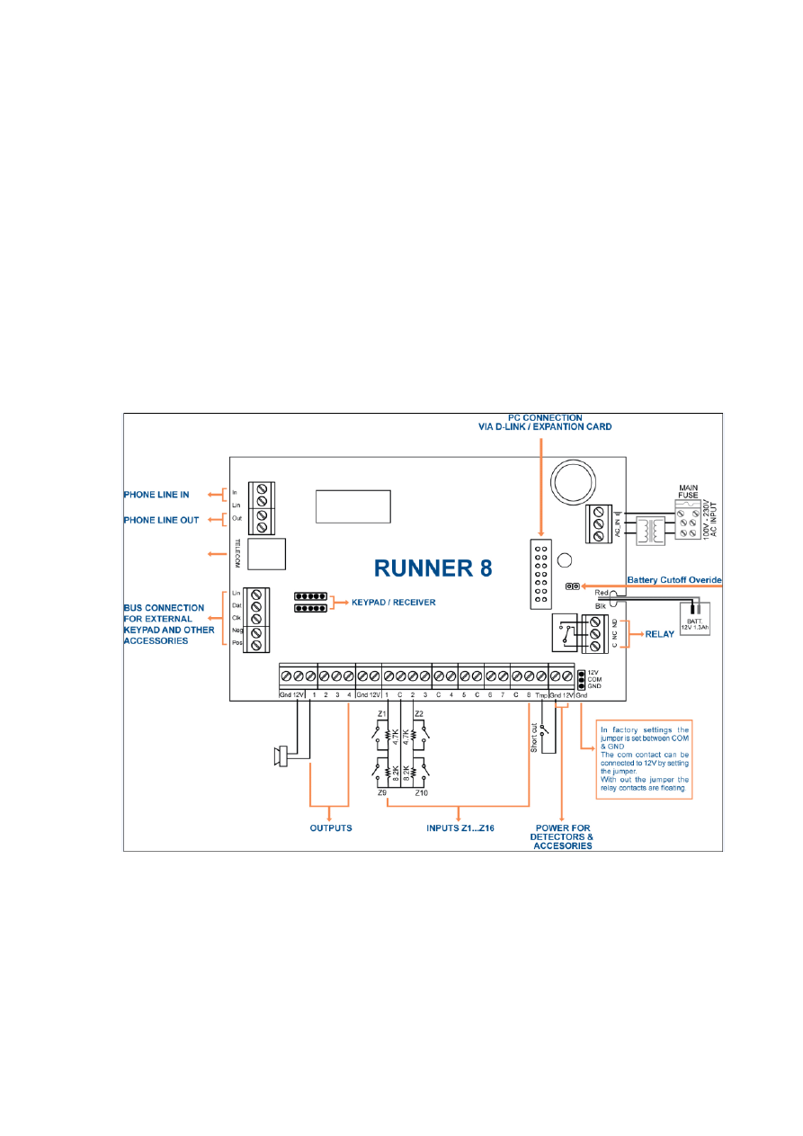
Connection Diagrams
Runner 8
The Runner 8 board is installed in three different enclosures:
PW-housing
COMPACT housing - has a 20VA transformer
MINI-housing – has a 25VA transformer
Battery Spec.: Sealed Lead-Acid Rechargeable Battery 12V/1.3Ah up to 12V /7Ah in the
Mini and PW-housings.
Battery Cutoff Level: (When AC mains fails) : 10 ± 0.3V

RUNNER - Installation & Config. Guide
7
Runner In Mini Box Specification :
Operating Voltage : 230V AC ,50Hz.
Transformer: 25VA
Fuse: TD 100mA /250V AC (SIBA Type 179120).
Back Up Battery: Lead Acid Battery 12V /1.3A up to 12V /7Ah
Battery Dynamic Test : Every 6 seconds.
Current Consumption:
Standby:
C.P = 40mA
Keypad =60-130mA Depend on Keys and Display backlight intensity.
Maximum Current Drain allowed from the C.P:
Standby: 400mA
Alarm: 900mA.
Inputs:
8 wired Zones 1-8 (Full Programmable).
Programmable Wired Tamper Input.
Outputs:
Output#1&2: Open Collector Type , 0.75A @12V DC..
Output#3&4: Open Collector Type , 0.5A @12V DC.
Output#4: Relay Change Over Contacts Capability: 2A @12V DC.
Protections:
12V Out : Each output power protected by reset able Fuse 0.75A.
Battery Out: Protected by reset able Fuse 2.5A.
POS : Protected by reset able Fuse 0.75A.
Physical:
Size:
Weight:
Operating Temperature: -10-50º C.
Storage Temperature: -20 - 60ºC.
Humidity: 85% relative humidity @ 30º C
RUNNER - Installation & Config. Guide
8
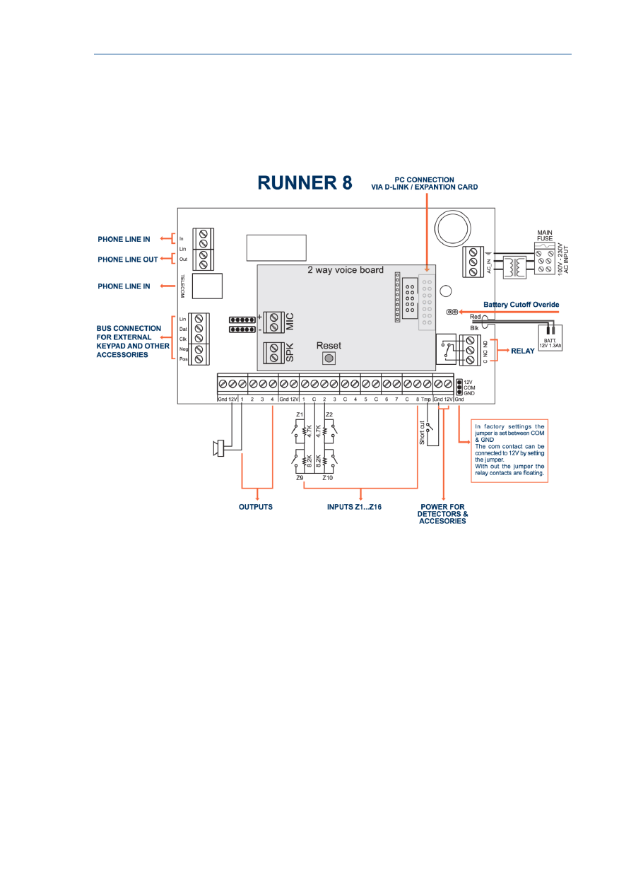
Runner Compact/FDX
The Runner FDX board is installed inside the Compact Box and together with a 20VA
transformer.

RUNNER - Installation & Config. Guide
9
Runner Compact /FDX Specification :
Operating Voltage : 230V AC ,50Hz.
Transformer : 20VA
Fuse: TD 100mA /250V AC (SIBA Type 179120).
Back Up Battery: Lead Acid Battery 12V /1.3A up to 12V /7Ah
Battery Dynamic Test : Every 6 seconds.
Current Consumption:
Standby: C.P = 40mA ,
Keypad =60-130mA,
Voice Board FDX=50-150mA
Alarm : 260mA.
Maximum Current Drain allowed from the C.P:
Standby: 300mA
Alarm: 800mA.
Inputs:
8 wired Zones 1-8 (Full Programmable).
Programmable Wired Tamper Input.
Outputs:
Output#1:
Internal Piezo with Driver connected
Output#2: Open Collector Type , 0.75A @12V DC..
Output#3&4: Open Collector Type , 0.5A @12V DC.
Output#4: Relay Change Over Contacts Capability: 2A @12V DC.
Protections:
12V Out : Each output power protected by reset able Fuse 0.75A.
Battery Out: Protected by reset able Fuse 2.5A.
POS : Protected by reset able Fuse 0.75A.
Physical:
Size:
Weight:
Operating Temperature: 0-50º C.
Storage Temperature: -10 - 55ºC.
Humidity: 85% relative humidity @ 30º C

RUNNER - Installation & Config. Guide
10

RUNNER - Installation & Config. Guide
11
Input Options
Different Input Configurations
The Runner 8 has nine separate programmable monitored analogue inputs.
These are:
Eight programmable multi-state detection inputs
One programmable tamper input (with optional Key-switch functions)
The input connector block is located on the board.
NOTE
Each input must be terminated with the appropriate value or combination of
End-Of-Line resistors, even if the input is unused.
Zone Inputs
Each of the Eight programmable zone inputs can be assigned one of the following End of Line
(EOL) configuration options,
Zone EOL Type (P125E) Input Resistor
Comments
0
(Short circuit)
Loop EOL
1
1k (Brown, Black, Red)
Single EOL
2
1k5 (Brown, Green, Red)
Single EOL
3
2k2 (Red, Red, Red)
Single EOL
4
3k3 (Orange, Orange, Red)
Single EOL
5
3k9 (Orange, White, Red)
Single EOL
6
4k7 (Yellow, Violet, Red)
Single EOL
7
5k6 (Green, Blue, Red)
Single EOL
8
6k8 (Blue, Grey, Red)
Single EOL
9
10k (Brown, Black, Orange)
Single EOL
10
12k (Brown, Red, Orange)
Single EOL
11
22k (Red, Red, Orange)
Single EOL
12
2k2 Tamper, 4k7 Zone
Zone & Tamper
13
3k3 Tamper, 6k8 Zone
Zone & Tamper
14
2k2 Tamper, 4k7 Low Zone,
8k2 High Zone
Zone Doubling with Tamper
15
4k7 Low Zone, 8k2 High Zone Zone Doubling without tamper
RUNNER - Installation & Config. Guide
12
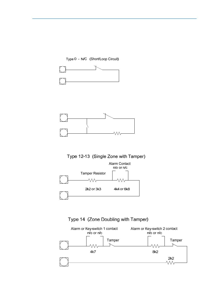
Zone Wiring Examples
Type 0 (Short/Loop Circuit)
Type 1-11 (Single EOL no Tamper)
EOL Resistor
N/C
N/O
Type 1-11 (Single EOL N/O Tamper)
Type 12-13 (Single Zone with Tamper)
Type 14 (Zone Doubling with Tamper)
RUNNER - Installation & Config. Guide
13
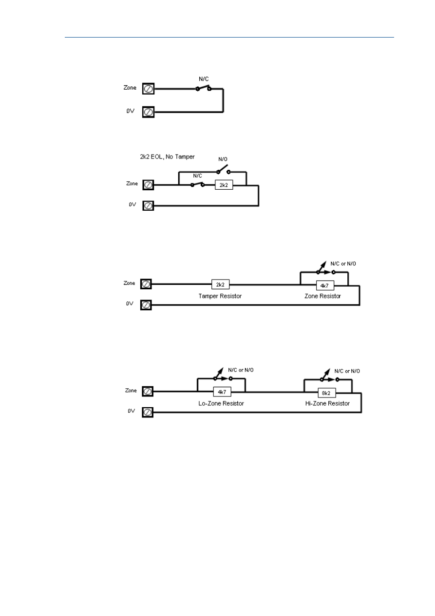
Short circuit loop, No EOL
2k2 EOL, No Tamper
Type 12 Configuration
Alarm & Tamper monitoring (contacts can be N/C or N/O).
Type 15 Configuration
Zone Doubling, NO Tamper (contacts can be N/C or N/O).
RUNNER - Installation & Config. Guide
14
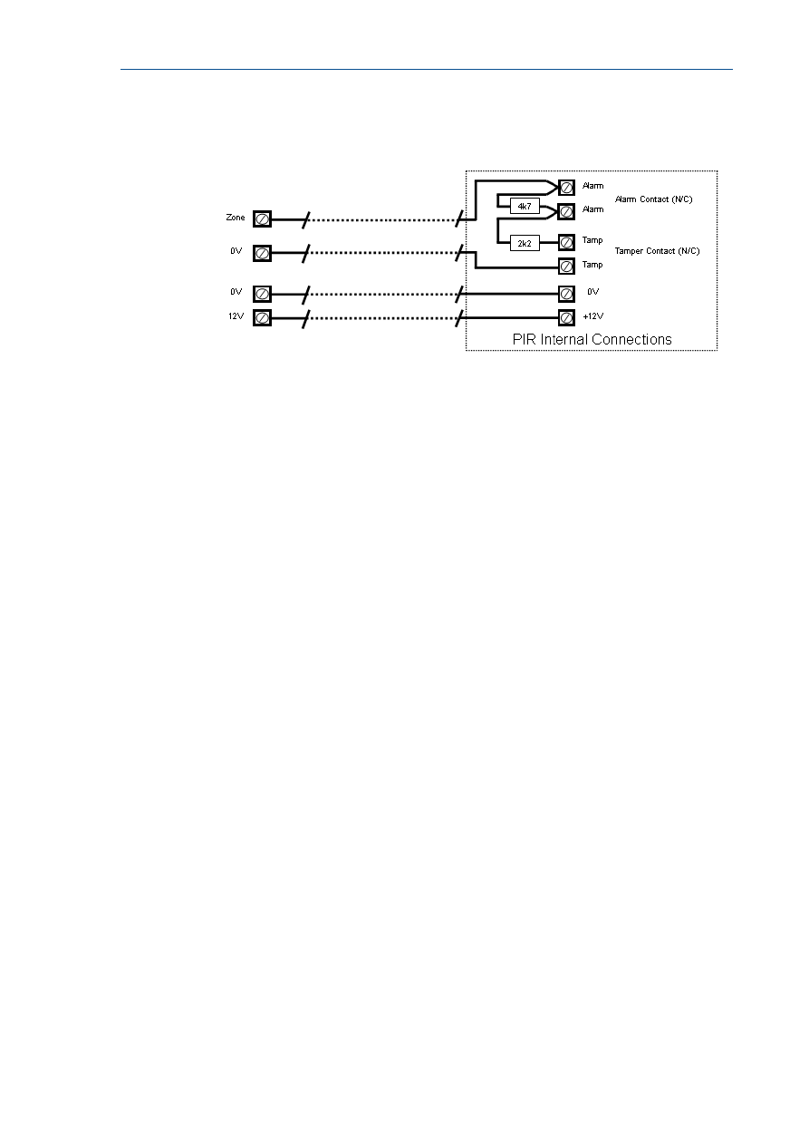
Wiring a PIR Detector (N/C) for Alarm & Tamper
Monitoring
Other Inputs
Tamper
A 24Hr tamper circuit is available for monitoring system tampers. This Tamper circuit is
programmable as either normally closed loop or 2k2 EOL supervision (the default is normally
closed loop). Any Tamper alarms on this input are mapped to alarm outputs in the same
manner as for detection zones 1-16. Using Dual-End-of-Line resistors (Refer to Zone Type 15
on Page 13) the Tamper input can also provide two key-switches. The Low key-switch (4k7
resistor) is Key-switch 1 while the High key-switch (8k2 resistor) is Key-switch 2.
In addition to the Zone & Tamper inputs, you will find the following additional inputs on the
control PCB;
AC
Connect the two low voltage wires (no polarity) from the transformer to the terminals
marked AC on the PCB. The panel includes a mains transformer rated at 15.5VAC.
Earth - not used
In case of using metal box connect the mains earth to the appropriate terminal on the mains
terminal block in the control box cabinet. Also connect a lead from this earth point to the
terminal marked with the Earth symbol (next to AC terminals) on the panel PCB.
Battery
Connect a sealed lead acid rechargeable 12VDC battery to the terminals labelled red and
black on the control panel being careful to observe the correct polarity. The maximum
recommended battery capacity is 7 amp hours. Battery charge current at these terminals is
limited to 260mA maximum. The battery connection is protected against short circuits by a
thermal fuse (F1).
Line In
These terminals are used to connect the panel to the incoming telephone line. The dialler
uses this line for reporting alarm events. An ADSL filter will be required before the Line in
terminal, in case there is ADSL in the building.

RUNNER - Installation & Config. Guide
15
Line Out
These terminals are used to connect telephones and other communication equipment to the
incoming phone line via the panel dialler circuit. The telephone line is passed through the
controller to ensure that the line is available to the controller when it is required.

16
Outputs
Description of Outputs
12 Volt Outputs
There are three 12VDC outputs on the panel PCB. These 12 volt outputs are regulated and
Thermal fuse protected against short circuits. The accessory outputs are marked 12V and
0V, while the keypad buss 12V supply is labelled “POS” & “NEG”. The 12V outputs are
supplied by thermal fuses F2 & F3. The maximum total load that allowed to be drawn from
all of the 12V outputs during an alarm is 0.9A.
Outputs 1 & 2
These fully programmable, high current, open drain (high-going-low) type FET outputs
capable of switching up to 1.5A @ 12VDC. These 2 outputs are normally set as switched
outputs, providing power for 12V sirens or piezos. If required, these outputs can be
programmed to be siren outputs designed to drive an 8 ohm 10 watt horn speaker on each
output (see P37E option 1). Also if a horn speaker is connected to Output #1 you may
select (Refer to P175E 7E program address) the listen-in feature to this output as well so
that the dialling sequence can be heard at the speaker.
Output 3 & 4
This is a low current, open drain (high-going-low) type FET outputs capable of switching up
to 500mA. Like Outputs 1 & 2 it is fully programmable. You cannot use with option 1 at
P37E on outputs 3 & 4.
NOTE
Connecting devices which draw current in excess of 500mA to output 3/4 can
damage the output.
Relay Out
This is a relay is related to Output 4 with single pole changeover contacts. If required, the
Common (C) contact of the relay is connected by default to GND via JUMPER, the jumper can
be selected to 12V or removed.
Keypad Port
The terminals marked POS, NEG, CLOCK, & DATA make up the communications port which
the keypads and other intelligent field devices use to talk to the controller. The terminals are
connected to corresponding terminals on the remote devices. The "line" terminal is only
used by the keypads and utilises a fifth wire to provide a communicator “listen-in” facility.
This feature is particularly useful when servicing monitoring faults. The keypad 12V supply
(POS,NEG) is protected by fuse F3.

RUNNER - Installation & Config. Guide
17
Expansion Port
The expansion port allows connection of the RS232 serial board, 90 second Voice Board,
DTMF Board or EEPROM data transfer board (DTU). The serial board allows direct connection
of a PC running the Upload/Download software. The 90 second voice board allows voice
messages to be programmed for monitoring purposes. The Voice & DTMF boards allow
Touchtone Code remote control via a telephone. The DTU allows for program “Cloning” from
one panel to another.

18
Accessories
Radio Receiver
The panel can have wireless capability via the FW-RCVR receiver module. The receiver will
add wireless capability to your system in the form or wireless PIR detectors, Wireless Radio-
key transmitters and wireless reed switch transmitters.
The FW-RCVR connects to the same communications port as the keypads. The FW-RCVR is
available in 3 frequencies, 916MHz,433MHz,868MHz. Multiple FW-RCVR can be connected to
the panel to increase the coverage range if desired.
The red LED fitted to the FW-RCVR receiver will flash at 1 second intervals when in "Learn"
mode (see P18E & P164E). The LED will also turn on when it is receiving an actual radio
transmission (On Steady).
Voice Board
The panel can also be fitted with a 90 second Voice Board module. The Voice board stores
either alarm event messages for Voice dial monitoring and /or status messages for use with
Command Control. The panel Voice Board are installed directly onto the motherboard via the
SERIAL socket.
Installation procedure for the Voice Board module is as follows.
1. Power-down the panel fully before starting the installation procedure.
2. Carefully plug the Voice Board into the SERIAL socket (it will only fit in one direction).
3. Power-up the panel.
Speech message programming
Once you have installed the Voice Board you can record your personalised speech messages
into the module with the speech programmer (the programmer plugs onto the 10 way strip
connector on the voice board).
Before programming your voice messages you should work out a list of the messages you
would like to be sent for each alarm type and write them down in order, giving them a
message number. These messages should then be recorded in the same order they are
written down so you know what the message number is letter when programming alarms to
messages.
To record your messages once the programmer is installed, first press the reset button on
the side of the Voice Board, then hold the programmer about 10 cm away from the mouth
and speak clearly at normal level into the microphone while holding down the "REC" button.
When you reach the end of your message release the REC button. (NOTE: Each individual
message must be longer that 2 seconds duration). When recording your voice alarm
message, you must ensure that you clearly identify the origin of the call. You can play the
message back through the programmer by first pressing the reset button then by pressing
the "PLAY" button momentarily. Because the panel can address many individual voice
messages you must store individual messages at what is known as recording slots within the
Voice Board. These recording slots are recorded sequentially, one message starting where
the other finishes. Every time you press and release the REC button on the programmer,
you create an end of message marker. These markers are used to define the recording slots
within the Voice Board and can be of varying length according to each message duration.

RUNNER - Installation & Config. Guide
19
To re-record your messages you must first press the "RESET" button on the speech module
to get back to recording slot # 1. Once you are at slot # 1 you can re-record your messages
in order as required.
NOTE
When recording multiple messages you only press the “RESET” button once at
the beginning then record all messages sequentially as stated above. When
you have finished recording all of your messages you can then press the
“RESET” button to allow play-back of the recording messages for verification
purposes.
When you have finished recording your alarm messages, unplug the programmer and the
process is complete. You must now go to the program addresses and assign the individual
messages to the specific functions.
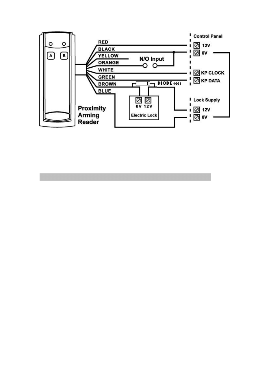
PW-Reader 2K: For arm/disarm area A and/or B.
The PW-Reader 2K is used for selective arming or disarming Area “A” or “B” or both.
By presenting a valid access tag or card to the reader the user can then Arm or Disarm the
panel using “A” & “B” buttons on the reader.
On presenting a valid tag to the reader, the current status of Areas A & B will be shown on
the two LED’s. The user has 4 seconds to make a new selection before the reader will
timeout and the tag will have to be re-presented again.
The Areas allowed to be controlled by the user must be programmed by the installer in the
Runner control panel. If the user is allowed to fully Arm, Disarm or Stay Mode then he can
cycle through the various states.
As button “A” or “B” is pressed the associated LED will change to indicate the new state:
For Disarmed state - the LED will be GREEN.
For Armed state - the LED will be RED.
For Stay Mode - LED would be flashing RED.
Four seconds after the last button was pressed the reader will action the new armed status
and the LED will turn off.
If the reader is programmed to allow “1 & 3 PANIC” functions, a “PANIC” alarm will be
generated if “A” & “B” buttons are pressed simultaneously (see P72E option 5).
NOTE
From the disarmed state you can select Armed or Stay modes but if already Armed or in
Stay Mode you MUST disarm first (letting the reader timeout) before you can select a new
armed state.
RUNNER - Installation & Config. Guide
20
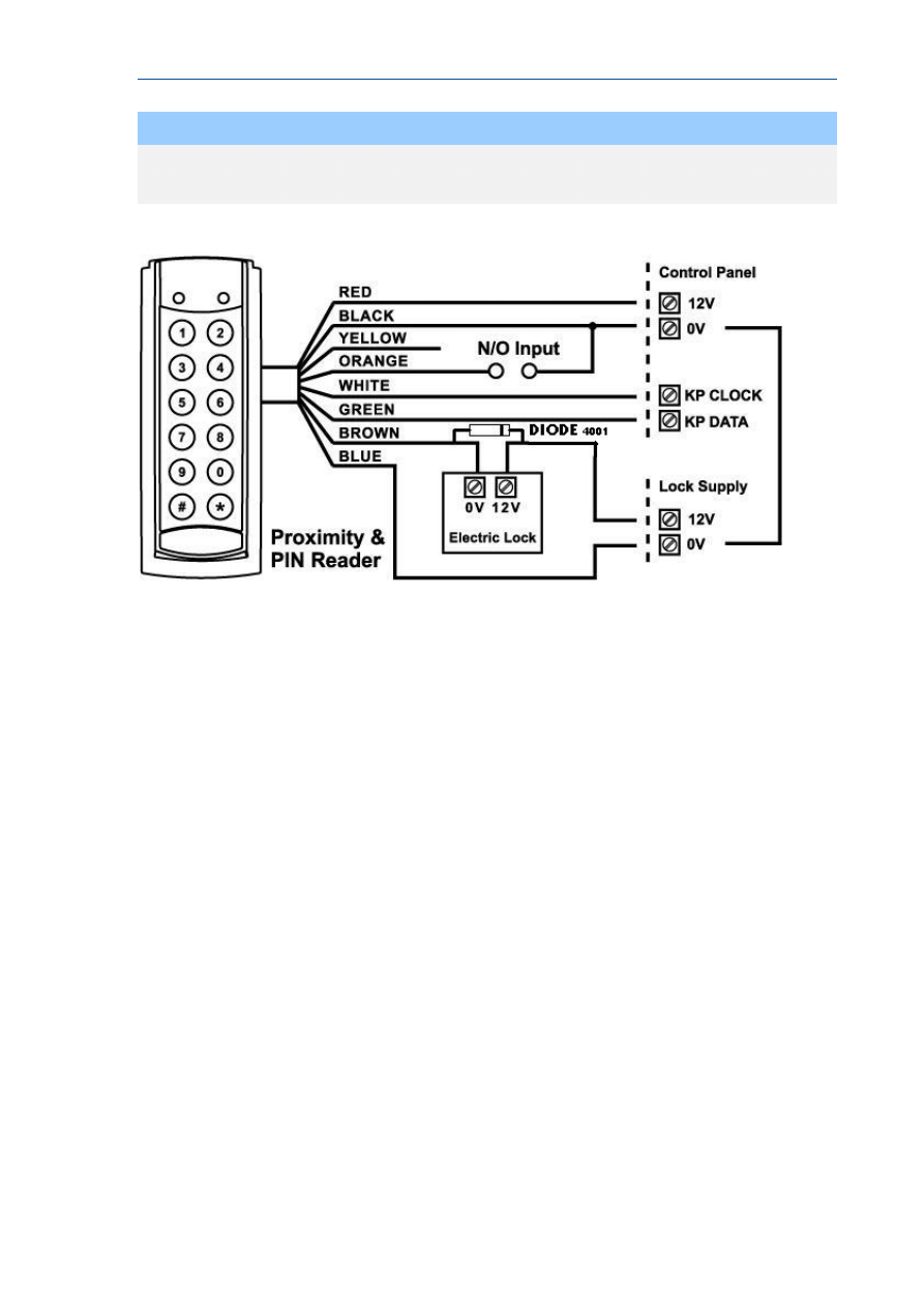
PW-Reader FK: Proximity and keypad (PIN) Access Reader.
The PW-Reader FK is used also as an access control reader, when the tag is presented; this
reader combines a proximity reader with a full keypad.
Depending on program options the reader can operate on a proximity tag or card, by
entering a valid user code, or by presentation of the tag/card followed by the user code
(PIN).
If the presented tag requires a PIN number to be entered, the LED on the reader will flash
for 5 seconds after a valid tag to indicate that the PIN number should now be entered. There
is also an output available on this reader that follows the same addressing functionality as
described above.
If the two buttons “PANIC”, “FIRE” or “MEDICAL” functions are programmed to the keypad
(see P72E Options 5,6 & 7) these manual alarms can be generated at the reader by pressing
“1” & “2” for “PANIC”, “3” & “4” for “FIRE” and “5” & “6” for “MEDICAL” alarms.
On each of the three readers there is an optional input (see drawings on page 22). This input
is not EOL monitored so it should only be used for non-critical monitoring functions, e.g.
monitoring an exterior gate to show if it is currently opened or closed. A zone can be
programmed to use this input for its trigger (see P122E Option 4) so that the state of the
input can be displayed on a keypad. The inputs are linked to the selected keypad address
programmed into the reader. For example if the reader being used was programmed as
keypad #1, then the input can be assigned to zone 1 or 9 (at location P122E), if the keypad
address was #8, the input can then be assigned to zone 8 or 16.
Also, the LED on reader types 2 & 3 can be linked to an output so that special functions may
be displayed at the reader if desired (see P98E).
Each reader must have a unique keypad address number from 1-8 assigned so that the
various program options can be assigned. This is explained in detail on Page 96.
RUNNER - Installation & Config. Guide
21
NOTE
The proximity readers flash out the assigned keypad address number on the LED
whenever the panel is in “Installer Program” Mode. This allows quick identification of
the assigned address for each reader.
RUNNER - Installation & Config. Guide
22
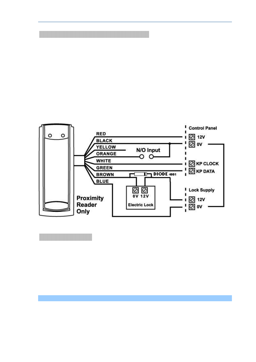
PW-Reader: Proximity Access Reader.
The PW-Reader (without keys) is generally going to be used as an access control reader
although if the tag is allowed to Arm/Disarm the alarm then this will also happen when the
tag is presented.
For access control, if a tag or card is presented to the reader the associated door lock will
release via an output on the control panel.
There is also an output at the reader which can be used to unlock the door if desired (see
drawing below for details).
The output number at the reader follows the keypad address number, e.g. if the reader has
been assigned to keypad address 5, the output at the reader will follow all programming
associated with output 5.
Assign the Reader
After a Reader has been connected to the bus, it has to get an address:
Select the “installer mode” in the control panel as described in the installer
manual.
Enter the code P99E followed by the address you wish to assign
(e.g. P99E4E will assign keypad address 4).
To address the reader you need to present a Card/Tag 5 times within 10 seconds
to the Reader.
When the address is learnt, the control panel stops the learn mode automatically.
Repeat the same steps for every reader address you want to assign.
Warning
If you do not assign a unique address to every keypad and reader connected to the keypad buss, a
conflict will exist that will cause erratic operation. Each reader or keypad MUST have a different
address.

RUNNER - Installation & Config. Guide
23
NOTE
The proximity and arming readers flash out the assigned keypad address number on their LED
whenever the panel is in “Installer Program” Mode. This allows quick identification of the assigned
address for each reader..
Card/Tag Learning
A Card has first to be enrolled into the system before starting to work with it.
All Cards/Tags are assigned to users. Therefore the Card/Tag storage options have to be
similar to the user ones (for example if user 11 is assigned to area A, then Card/Tag
number 11 will be assigned to area A as well).
Select the “program mode” in the control panel as described in the installer manual.
Enter P21E and the Card/Tag number you wish to enrol, i.e. 11E for tag/card number 11:
the keypad will start to beep to indicate that learn mode has been started.
Present the Card/Tag to the READER:
once the Card/Tag has been received by the control panel and stored, the READER will stop
beeping to indicate learn mode is completed.
After learning process, in order to enable the tag operation, you MUST select the
appropriate option at location P2E (options 2, 3 or 4 must be selected for the Card/Tag to
work) on the control panel.
DELETE an ACCESS TAG/CARD CODE
DELETE an ACCESS TAG/CARD CODE - P22E 1-100E
If you wish to delete a single Access Tag or Card, pressing P22E then the User number
while in Program Mode will delete the stored code against that User, eg P22E 11E will
remove the tag or Card stored for User 11.
FIND an ACCESS TAG/CARD LOCATION
FIND an ACCESS TAG/CARD LOCATION - P23E 0E
If you have an Access Tag or Card loaded into the panel but are unsure which location (User
#), pressing P22E (then 0E on an LED Keypad) while in Program Mode will start “Find”
Mode. There is no need to press 0E when using an LCD keypad because the keypad will give
you written prompts after entering P22E. The keypad will start to beep to indicate that
“Find” mode has been started. Now present the Access Tag or Card you wish to find to a
proximity reader connected to the panel. If the Tag or Card is in memory the keypad will
display the number where the Tag or Card is stored (a number from 1-100). The keypad
will stop beeping once the memory location has been found.
Assign Chirps to Access Tags
AREA OPTIONS “B” - P46E 1-2E
– Option 4
If the panel is being Armed or Disarmed by an Access Tag/Card from a proximity reader it is
possible to link the pendant chirps programming (P50E-P53E) to Arming or Disarming via
the Access Tag or Card. If this option is On the chirps will apply to Access Tag/Cards. If the
chirps are required to be displayed at the reader LED, the minimum pulse timer for the
output (P39E) must be a value of 10.

RUNNER - Installation & Config. Guide
24
Proximity Reader Led To Output Mapping
PROXIMITY READER LED to OUTPUT MAPPING - P98E 1-8E
Option 1 - Proximity Reader 1-8 LED follows Output 1
Option 2 - Proximity Reader 1-8 LED follows Output 2
Option 3 - Proximity Reader 1-8 LED follows Output 3
Option 4 - Proximity Reader 1-8 LED follows Output 4
Option 5 - Proximity Reader 1-8 LED follows Output 5
Option 6 - Proximity Reader 1-8 LED follows Output 6
Option 6 - Proximity Reader 1-8 LED follows Output 7
Option 7 - Proximity Reader 1-8 LED follows Output 8
If a proximity reader is connected to the control panel it may be desirable to have the LED
provide some form of indication such as Arm/Disarm state, etc. By using this location it is
possible to link the LED at a reader number to follow the programming of an output. The
LED can be used to indicate Arm/Disarm state, Stay Mode Arm/disarm, output On/Off, etc.
If chirps have been assigned to access tags/cards (P46E4E) and the output the reader LED
is set to follow has the chirps assigned (P50E-P53E), then the output must have a minimum
pulse time (P39E) of 10 for it to work correctly.
The proximity reader keypad address number is set at P99E as detailed below.
Assign Zone to Reader
ZONE OPTIONS A - P122E 1-16E Option 4: Keypad Zone
If this option is on the Zone will follow the Input at the corresponding Proximity Reader. If
the Proximity Reader is set to Keypad # 1 the input will be either zone 1 or zone 9, eg if
P122E1E (zone #1) had option 4 on then the input at reader one will operate zone 1. If
P122E9E (zone #9) had option 4 on then the input at reader one will operate zone 9.
Proximity reader 1 can operate zones 1 or 9 through to proximity reader 8 can operate
zones 8 or 16.
RUNNER - Installation & Config. Guide
25
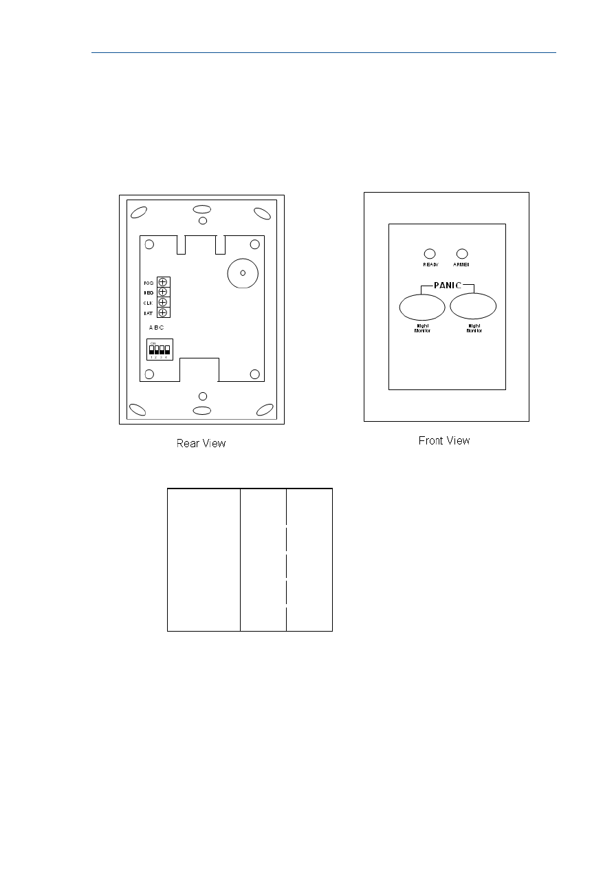
Night Monitor Keypad
The Night Monitor Keypad is designed to be a simple night arming station typically used in a
bedroom situation.
By pressing either of the <Night Monitor> buttons the alarm Stay Mode can be armed or
disarmed. If both buttons are pressed simultaneously, a Panic Alarm can be generated. A 4
way DIP switch on the rear of the unit sets various options. The DIP switch functions and the
programming requirements are detailed below.
The Night Monitor keypad can be set to keypad addresses 5-8 by using Switches 1 & 2. Refer
to chart below
DIP Switch
1
2
KP No: 5
OFF
OFF
KP No: 6
ON
OFF
KP No: 7
OFF
ON
KP No: 8
ON
ON
Switch 3 is unused on the Runner 8/16. It is used to force the armed LED to follow area A or
B on other control panels.
Switch 4 MUST be OFF (if Switch 4 is ON the unit will work with earlier version 4 & 5 control
panels).
Night Monitor Panel Programming
The Night Monitor button is designed to arm or disarm Stay Mode. The Stay Mode Area is
assigned to the keypad at location P76E.
The functions of the button are programmed at location P77E (eg for the button to Arm Stay
Mode and be able to Disarm Stay Mode at all times you must have options 2 & 4 ON).

RUNNER - Installation & Config. Guide
26
The “ARMED” LED function is programmed at location P71E. For example if the Night Monitor
keypad is only assigned to area A and you only want the Armed LED to show the status of
area A you should turn on Option 1 (Area A) at location P71E for the address assigned to the
Night Monitor keypad.
If both Night Monitor buttons are pressed simultaneously, it is possible to generate a
“PANIC” alarm. To enable the panic alarm function for the keypad number assigned you
must have option 3 turned on at location P72E.
RUNNER - Installation & Config. Guide
27
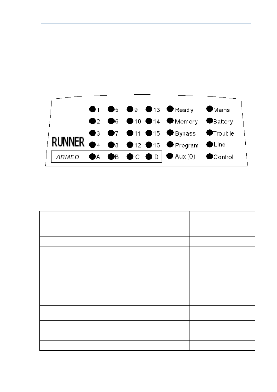
Keypad Indicators
LED Keypad
Standard Runner 8/16LED Keypad Window Layout
When the Panel is displaying codes and address values in program mode it may be
necessary to display the 0 digit. As there is no Zone indicator for 0 the "AUX (0)" indicator is
used to show the number “0”.
The Chart below gives details on the various indicators on the LED keypad and what they
mean.
LIGHT\INDICATION
OFF
ON STEADY
FLASHING
READY
Zone Unsealed
All Zones Sealed
-
MEMORY
Normal
Memory Display Mode
New Memory Event
BYPASS
Bypass Off
Zone Bypass Mode
Active
Zone/s Bypassed
PROGRAM
Run Mode
Client Program Mode
Installer Program Mode or
Control Function Active
AUX (0)
Chime Mode ON
Chime Mode OFF
-
MAINS
-
Mains (AC) OK
Mains (AC) Fail
BATTERY
-
Battery OK
Battery Low
TROUBLE
Normal
Trouble (Tamper) Alarm
Active
New Trouble (Tamper) Alarm
LINE
Telephone line is OK Dialler is currently
making a call
The Telephone line has been
cut or the call was not
completed
CONTROL
Control Function OFF Control Mode On
RUNNER - Installation & Config. Guide
28
LIGHT\INDICATION
OFF
ON STEADY
FLASHING
ZONES 1-16
Zone Secure
Zone Unsealed (Not
Ready)
Zone in Alarm
ARMED A
Partition A Disarmed Partition A Armed
Partition A Stay Mode
ARMED B
Partition B Disarmed Partition B Armed
Partition B Stay Mode
ARMED C
Spare
ARMED D
Spare
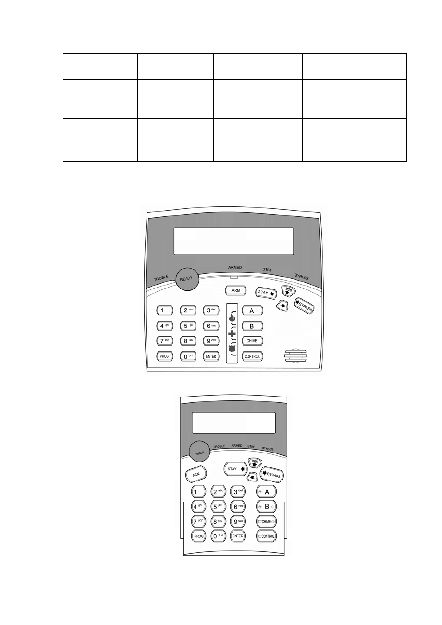
Runner LCD KEYPAD
CROW BIG LCD
CROW SMALL LCD

RUNNER - Installation & Config. Guide
29
The table below gives details on the various LED indicators on the keypad and what they
mean.
LIGHT\INDICATION
OFF
ON STEADY
FLASHING
READY
Zone Unsealed
All Zones Sealed
-
TROUBLE
Normal
Trouble (Tamper)
Alarm
Active
New Trouble (Tamper)
Alarm
BYPASS
Bypass Off
Zone Bypass Mode
Active
Zone/s Bypassed
ARMED A
Partition A or B
Disarmed
Partition A or B Armed
STAY
STAY Disarmed
STAY Armed
Keypad Memory Display - LED Keypad
Current Alarm Systems
When viewing the memory event buffer at the keypad by pressing the “MEMORY” button,
the first thing that will always be displayed are any Current System Alarms that are active.
The Current System Alarms are indicated by the Memory/Mains & Battery LEDS being on
plus a zone LED from 1-8 to indicate the system alarm/s present. If no Zone LED’s are on at
this time, it means that there are no current system alarms. If a zone LED or LED’s are On
then this indicates system alarms that have not yet cleared. The zone LED’s 1-8 are pre-
defined as to what system alarm they will display. These system alarm indications are shown
in the table below. Following the display of current system alarms the panel will then
sequence through the 255 historical memory events starting at the most recent event.
CURRENT SYSTEM ALARMS
LED # 1 Battery Low
LED # 5
Radio Pendant Battery Low
LED # 2 Mains, 12V Fuse or Output
Failure
LED # 6
Supervised Detector Failure
LED # 3 Telephone Line Failure
LED # 7
Sensor Watch or Delinquency Alarm
LED # 4 Radio Detector Battery Low
LED # 8
Dialler Kiss-off Failure
HISTORICAL MEMORY EVENTS
Following the “Current System Alarms” the panel will display the historical memory events.
The panel stores the most recent events, (up to 255), including all alarm events, all system
events such as mains failure etc as well as arming by Area. The memory events are
displayed via the standard keypad with the most recent event shown first and subsequent
events following in descending order from newest to oldest.

RUNNER - Installation & Config. Guide
30
The "MEMORY" light will be on while the memory display mode is active. To view events
simply press the “MEMORY” button. The keypad will beep and the display is advanced to
the next event every time the “MEMORY” button is pressed. When all events in memory
have been displayed the keypad will exit memory mode and return to the normal idle state.
To cancel the memory display just press “ENTER”. If the “ENTER” button is not pressed and
the display mode is not advanced to the last memory event, the keypad will automatically
exit memory display mode after approximately 20 seconds. The memory light will turn off
once the memory display mode has been exited. The MEMORY LED flashes when there is a
new event in memory and it will stop flashing once the event has been viewed or the panel
is armed.
The Chart below gives details on the various alarms and what LED
indicators are used to display them.
HISTORICAL EVENT DISPLAY CHART
EVENT DEVICE
INDICATOR
STATUS
ACTIVATION
Zones 1-16
LED's 1-16
On Steady
BYPASS Zones
1-16
BYPASS
LED's 1-16
On Steady
On Steady
DETECTOR TAMPER
(SHORT CIRCUIT)
Zones 1-8
TROUBLE
LED's 1-8
Flashing
On Steady
DETECTOR TAMPER
(OPEN CIRCUIT)
Zones 9-16
TROUBLE
LED's 9-16
Flashing
On Steady
CABINET TAMPER
Cabinet or Satellite Siren
TROUBLE
Flashing
WRONG CODE ALARM
Code Tamper at
Keypad #
TROUBLE
LED’s 1-8
Flashing
On Steady
CROW KEYPAD TAMPER
SWITCH ACTIVATED
Keypad Tamper Alarm at
Keypad #
TROUBLE
LED’s 1-8
On Steady
On Steady
LED KEYPAD VIEW MEMORY MODE cont
HISTORICAL EVENT DISPLAY CHART-Continued
EVENT DEVICE
INDICATOR
STATUS
LOW BATTERY
Controller Battery BATTERY
Flashing
MAINS FAILURE
Controller Mains
Supply
MAINS Flashing
12V Output FAILURE (F2 or
F3)
Controller on-board
Thermal fuses
activated
MAINS
LED 1
Flashing
On Steady
OUTPUT 1 or 2 FAIL
(Only applies if siren or strobe
connected)
Wires to Output 1 or 2
have been cut
LED’s 1 or 2
TROUBLE
MAINS
On Steady
On Steady
On Steady

RUNNER - Installation & Config. Guide
31
HISTORICAL EVENT DISPLAY CHART-Continued
EVENT DEVICE
INDICATOR
STATUS
LOW BATTERY-ZONE
(Wireless detector)
Radio Zone
Zone 1-16
BATTERY
LED's 1-16
Flashing
On Steady
LOW BATTERY-PENDANT
(wireless Transmitter)
Radio Key
User 21-100
BATTERY
LINE
CONTROL
Flashing
Flashing
On Steady
SENSORWATCH TIMEOUT
Zone 1-16
LED’s 1-16
TROUBLE
CONTROL
On Steady
Flashing
Flashing
SUPERVISED RADIO TIMEOUT Zone 1-16
LED’s 1-16
TROUBLE
BYPASS
On Steady
Flashing
Flashing
RF FAILURE
No RF Activity
TROUBLE
AUX (0)
Flashing
Flashing
ARM DELINQUENCY ALARM
Area A or B not armed
within programmed
number of days
TROUBLE
CONTROL
Flashing
Flashing
DURESS ALARM
Duress Alarm
(at Keypad #)
TROUBLE
LINE
LED’s 1-8
Flashing
Flashing
On Steady
KEYPAD PANIC
Panic Alarm at Keypad LINE
LED’s 1-8
Flashing
Flashing
PENDANT PANIC
Radio Panic Alarm
LINE
Flashing
KEYPAD FIRE
Fire Alarm at Keypad
LINE
CONTROL
LED’s 1-8
Flashing
Flashing
On Steady
KEYPAD MEDICAL
Medical Alarm at
Keypad
LINE
BYPASS
LED’s 1-8
Flashing
Flashing
On Steady
ARMED
Area "A" Armed
"A"
On Steady
ARMED
Area "B" Armed
"B"
On Steady
STAY MODE ON
Area "A" in Stay Mode "A"
Flashing
STAY MODE ON
Area "B" in Stay Mode "B"
Flashing
TELEPHONE LINE FAIL
Panel Dialler
LINE
On Steady
EXCESSIVE RE-TRIES
Panel Dialler
LINE
LED 1
On Steady
On Steady

RUNNER - Installation & Config. Guide
32
HISTORICAL EVENT DISPLAY CHART-Continued
EVENT DEVICE
INDICATOR
STATUS
FAILURE TO GET A KISSOFF Panel Dialler
LINE
LED 2
On Steady
On Steady
WALKTEST MODE
Manual Walk-test
Mode
MAINS
BATTERY
LINE
LED’s 1-16
On Steady
On Steady
On Steady
On Steady
LCD KEYPAD
LCD Keypad View Memory Mode
The LCD Keypad has similar operational functions to the LED keypad with one notable
exception, when displaying Memory Events in “Memory Mode” it will display the events using
plain text messages with the Time & date that the event occurred.
This makes the fault diagnosis much easier. On an LED keypad only the ARM indications are
displayed (the disarm is removed from the display) but with the LCD keypad all events can
be displayed (including when the system was disarmed and by who).
To access “Memory Mode” using the LCD keypad, press the “MEMORY” button.
There are two parts to the Memory Display Mode:
CURRENT SYSTEM ALARMS
If there are any current “SYSTEM” alarms, they will be displayed first under the heading of
“CURRENT ALARMS”.
There are up to 8 “system alarms” that can be displayed at this point. They are listed in the
“Current System Alarms” table on page 29. The current system alarms will be displayed in
plain text to describe the actual problem. If there is more than one current problem the
keypad will display event alarm sequentially with the heading of “CURRENT ALARMS” on the
top line and the alarm on the bottom line.
Each time the “MEMORY” button is pressed, the next alarm will be displayed.
If there are no system problems with the panel the display will show “NO FAULTS”.
When all current system alarms have been displayed the keypad will then start to show the
historical memory events.
HISTORICAL MEMORY EVENTS
Following the “Current System Alarms” the panel will display the historical memory events.
The panel stores the most recent events, (up to 255), including all alarm events, all system
events such as mains failure etc as well as arm/disarm by User & Area. The memory events
are displayed via the LCD keypad with the most recent event shown first and subsequent
events following in descending order from newest to oldest.
During the “Historical Memory Event” display mode the LCD display will show the type of
event on the top line eg “Area A armed by User 1” and the actual time and date that the
event occurred on the bottom line.
To view events simply press the “MEMORY” button. The keypad will beep and the display is
advanced to the next event every time the “MEMORY” button is pressed.
If you wish to go back and look at an earlier event you can use the “” or “STAY” buttons
to go back to an earlier event. Each time the Down arrow is pressed the memory will go
back one event.

RUNNER - Installation & Config. Guide
33
When all events in memory have been displayed the keypad will exit memory mode and
return to the normal idle state. To cancel the memory display just press “ENTER”.
If the “ENTER” button is not pressed and the display mode is not advanced to the last
memory event, the keypad will automatically exit memory display mode after approximately
20 seconds.
When there is a new event in memory the words “ NEW MEM EVENT” will be shown on the
LCD display.
The “ NEW MEM EVENT” display will be reset once the event has been viewed or the panel is
armed.

34
Keypad Address Assignment &
Installation
LED Keypad
Installation
To separate the two keypad halves of the Crow Slim-line LED Keypad, unscrew the
fastening screw at the bottom of the keypad.
Screw the base to the wall using the mounting holes provided. These holes will match the
standard single switch plate spacing. Ensure the base is mounted right side up. The screw
should be at the bottom on the Crow keypad base. When fixing the base to the wall make
sure the top of the screw heads will not touch or short out the underside of the PCB when
the top half of the keypad is reinstalled. Bring the cables through the centre of the base.
Connect the 4 wires to the 5 way terminal block on the rear of the keypad PCB making sure
to match the cables up with the terminals as marked on the control panel's keypad port. The
5th wire is an optional “Listen-in“ connection. It is connected from the "LIN" terminal of the
keypad to the "Lin" terminal of the panel keypad port. With the Listen-in wire connected the
user to hear the call progress during dialling at the keypad (provided the desired program
options at address P175E 6E are turned on).
Once the cables have been terminated and the required address allocated (see section
below) fit the front half of the keypad onto the base.
The maximum recommended cable using standard 0.2mm security cable is 50m. Cable runs
exceeding this distance may require 0.5mm cable. Always use good quality cable. Some
installations may require CAT5 data cable to ensure data integrity in noisy sites.
Led Keypad Address Assignment
A total of 8 devices (keypads or proximity readers) can be connected to the panel. Each
keypad must be addressed individually to avoid BUS conflicts when multiple users are
operating different keypads simultaneously. By default, each keypad comes addressed as KP
# 1.
Setting the LED keypad address is done in “Local Program Mode”.
To enter “Local Program Mode” on the LED Keypad you must press and hold the
<CONTROL> button down and within 2 seconds, press the <BYPASS> button.
The “PROGRAM” LED will turn on plus the current keypad address will be displayed on the
zone LED’s.
The default setting is address 1 so zone LED 1 will also be on.
To change the keypad address so that it is different to others connected to the panel press a
number on the keypad from 1-8 relating to the address you wish to assign to the keypad,
e.g. if the keypad is the second one connected to the panel and the other keypad is set to
address 1, press 2 to select keypad address 2 for this keypad. The selected address will be
displayed on the zone LED’s (in this example LED 2 would be on).
To Exit “Local Program Mode” press the <ENTER> Button.

RUNNER - Installation & Config. Guide
35
The “PROGRAM” LED will turn off and the display will return to normal with the mains &
battery LED’s on.
If you do not assign a unique address to every keypad and reader connected to the
keypad buss, a conflict will exist that will cause erratic operation. Each reader or
keypad MUST have a different address.
Led Keypad Tamper Switch
Some LED keypads may have a tamper switch fitted. If the switch is fitted, the tamper
monitoring is inhibited until the tamper switch is closed for the first time. After that if the
switch is opened a keypad tamper alarm will be generated. If the keypad has provision for a
tamper switch but the switch is not fitted, the keypad tamper alarm will be permanently
inhibited because it can never be closed to start the tamper monitoring.
LCD KEYPAD
Installation
To separate the two keypad halves of the Crow LCD Keypads, unscrew the fastening screw
at the bottom of the keypad.
Screw the base to the wall using the mounting holes provided. These holes will match the
standard single switch plate spacing. Ensure the base is mounted right side up. The screw
should be at the bottom on the Crow keypad base. When fixing the base to the wall make
sure the top of the screw heads will not touch or short out the underside of the PCB when
the top half of the keypad is reinstalled. Bring the cables through the centre of the base.
Connect the 4 wires to the 5 way terminal block on the rear of the keypad PCB making sure
to match the cables up with the terminals as marked on the control panel's keypad port. The
5th wire is an optional “Listen-in“ connection. It is connected from the "LIN" terminal of the
keypad to the "Lin" terminal of the panel keypad port. With the Listen-in wire connected the
user to hear the call progress during dialling at the keypad (provided the desired program
options at address P175E 6E are turned on).
Once the cables have been terminated clip the front half of the keypad onto the base.
The maximum recommended cable using standard 0.2mm security cable is 50m. Cable runs
exceeding this distance may require 0.5mm cable. Always use good quality cable. Some
installations may require CAT5 data cable to ensure data integrity in noisy sites.
LCD Keypad Address Assignment
A total of 8 devices (keypads or proximity readers) can be connected to the panel. Each
keypad must be addressed individually to avoid BUS conflicts when multiple users are
operating different keypads simultaneously. By default, each keypad comes addressed as KP
# 1.
Setting the LCD keypad address is done in “Local Program Mode”.
Accessing “Local Program Mode” :
To enter “Local Program Mode” on the Crow LCD Keypad you must press and hold the
<CONTROL> button down and within 2 seconds, press the <ARM> button.
When in Local Program Mode the display will show local mode kb 1 with the number 1
meaning the keypad address is currently 1.
To change the keypad address to be different to others connected on the panel press;
<PROGRAM> 996 <ENTER>
The display will now show;

RUNNER - Installation & Config. Guide
36
Keypad number 1
Select an unused address, e.g. “2” then press <ENTER> to save.
To exit “Local Program Mode” press and hold the <PROGRAM> Button for two seconds.
You can select the program location directly as shown above or there is also a menu function
to navigate the various options in “Local Edit Mode” that is described in detail on page 38.
If you do not assign a unique address to every keypad and reader connected to the
keypad buss, a conflict will exist that will cause erratic operation. Each reader or
keypad MUST have a different address.
Adjusting Backlighting and Buzzer Tone
Adjusting the LCD Keypad Backlighting
The user can independently adjust the backlight level of the LCD display and the Keypad
Buttons from off to on with 16 steps in between. The Buttons used for these special
functions vary depending on the LCD keypad.
To increase the Crow LCD backlight level Press “CONTROL” followed within 2 seconds by
“STAY”. By holding down the “Control” button and repeatedly pressing the “STAY (Left
Arrow)” button you can increase the LCD backlight level to the maximum.
To reduce the Crow LCD backlight level Press “CONTROL” followed within 2 seconds by
“BYPASS”. By holding down the “Control” button and repeatedly pressing the “BYPASS (Right
Arrow)” button you can decrease the LCD backlight level until it is off.
To increase the Crow Keypad Button backlight level Press “CONTROL” followed within 2
seconds by “MEM”. By holding down the “CONTROL” button and repeatedly pressing the
“MEM (Up Arrow)” button you can increase the Keypad LED backlight level to the
maximum.
To reduce the Crow Keypad Button backlight level Press “CONTROL” followed within 2
seconds by “”. By holding down the “CONTROL” button and repeatedly pressing the “
(Down Arrow)” button you can decrease the Keypad LED backlight level until it is off.
Adjusting the Keypad Buzzer Tone
The user can adjust the frequency (tone) of the LCD keypad buzzer within a range of 16
steps. By adjusting the frequency the volume of the tone produced at the buzzer varies as well.
To increase the frequency of the CROW LCD buzzer Press “CONTROL” followed within 2
seconds by “A”. By holding down the “CONTROL” button and repeatedly pressing the “A”
button you can increase the frequency of the buzzer tone.
To decrease the frequency of the CROW LCD buzzer Press “CONTROL” followed within
2 seconds by “B”. By holding down the “CONTROL” button and repeatedly pressing the “B”
button you can decrease the frequency of the buzzer tone.

37
LCD Keypad “Local Edit” Mode
LCD Keypad
The Local Edit Program Mode allows the programming of a customised “System Name” (the
name displayed during idle mode at the keypad), Customised “Zone Names” (the text that
appears on the keypad when a zone is unsealed), Customised “User Names” (the User name
will appear when viewing arm/disarm events in memory mode), Customised “Area Names”
(the Area name will appear when viewing arm/disarm events in memory mode) and
Customised “Output Names” (the Output name will appear when viewing Output On/Off
events in memory mode).
Accessing Local Edit Mode
To enter Local Edit Program Mode on a CROW LCD Keypad Press “CONTROL” followed by
“ARM” and hold for 2 seconds.
NOTE
You must press the “Control” button first and the “Bypass” or “Arm” button
must be pressed within 5 seconds of pressing the Control button. If you make
a mistake press the “Enter” button then repeat the process.
The display will now show “Local Mode kb #” where the # equals the keypad address as
previously set (see “LCD keypad address assignment” on page 35 for details). There are two
ways to program the keypad in “Local Edit Mode”. You can enter in the program location
directly from the list below or you can use the menu function to navigate through all of the
program options. The menus are described on the following pages.

RUNNER - Installation & Config. Guide
38
Local Edit Mode Direct Program Addresses
There are a number of program addresses available to you at this point. They are;
[PROG]-[1]-[ENTER] to;
ZONE#1 TEXT (maximum 16 characters)
[PROG]-[16]-[ENTER]
ZONE#16 TEXT
[PROG]-[800]-[ENTER]
UPDATE EDITABLE TEXT TO ALL LCD KEYPADS
[PROG]-[801]-[ENTER]
RETURN ALL EDITABLE TEXT TO DEFAULT
[PROG]-[995]-[ENTER]
PANEL TYPE
[PROG]-[996]-[ENTER]
SET KEYPAD ADDRESS NUMBER FROM 1-8
[PROG]-[997]-[ENTER]
KEYPAD LANGUAGE
[PROG]-[998]-[ENTER]
AREA IDENTIFYING CHARACTER (assigning numbers
or letters to Areas)
[PROG]-[999]-[ENTER]
PANEL NAME DISPLAY (maximum 16 characters)
PROG]-[1001]-[ENTER] to;
PROGRAM USER “1” NAME
PROG]-[1100]-[ENTER]
PROGRAM USER “100” NAME
[PROG]-[2001]-[ENTER]
AREA “A” IDENTIFYING NAME (maximum 16 character
Area name)
[PROG]-[2002]-[ENTER]
AREA “B” IDENTIFYING NAME (maximum 16 character
Area name)
PROG]-[3001]-[ENTER] to;
PROGRAM OUTPUT “1” NAME
PROG]-[3008]-[ENTER]
PROGRAM OUTPUT “8” NAME
Keypad Tamper Switch
Some LCD keypads may have a tamper switch fitted. If the switch is fitted, the tamper
monitoring is inhibited until the tamper switch is closed for the first time. After that if the
switch is opened a keypad tamper alarm will be generated. If the keypad has provision for a
tamper switch but the switch is not fitted, the keypad tamper alarm will be permanently
inhibited because it can never be closed to start the tamper monitoring.
LCD KEYPAD “LOCAL EDIT” MODE MENU PROGRAMMING
The LCD Keypad Main menu headings for “Local Edit” program mode are listed on this page.
On entering Local Edit Mode the display will look like the example below.
To move to the next menu heading simply press the arrow. To move back to the previous
heading simply press the Arrow.
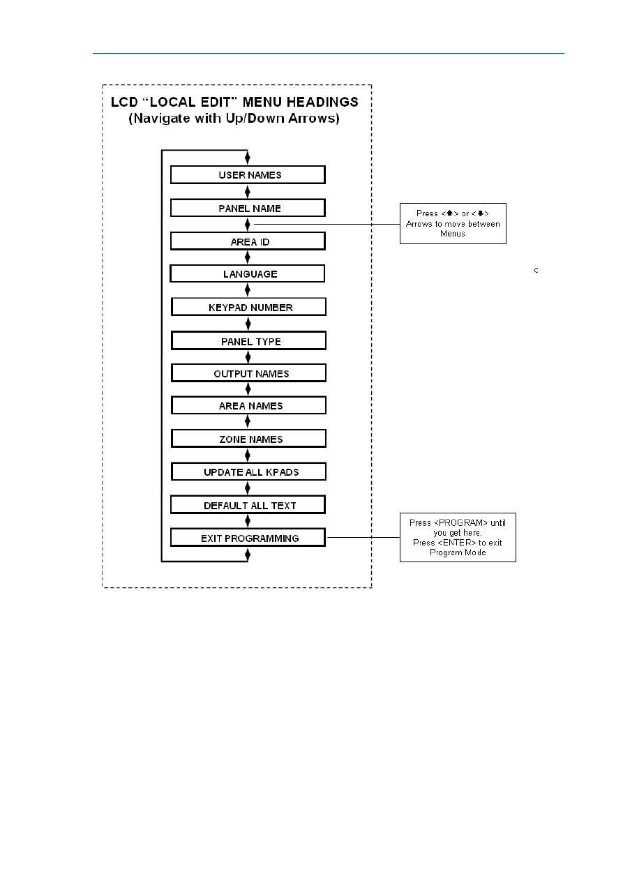
RUNNER - Installation & Config. Guide
39
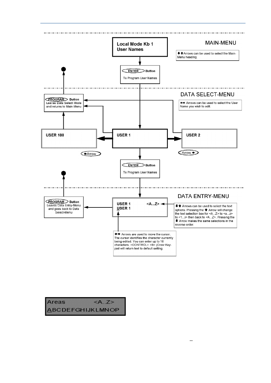
RUNNER - Installation & Config. Guide
40
When you are at the desired main menu heading, press <ENTER> to access the data
program location. See example below
Changing the Area Single Character Identifier
When you enter in [PROG]-[998]-[ENTER] the display will look like the example above.
You may edit the single character Area identifier at this address starting at Area “A” (first
left-hand position). The keypad allows for up to 16 areas but the actual number of areas
supported on this panel is two. The first character (in this case the ”A”) is the identifier used
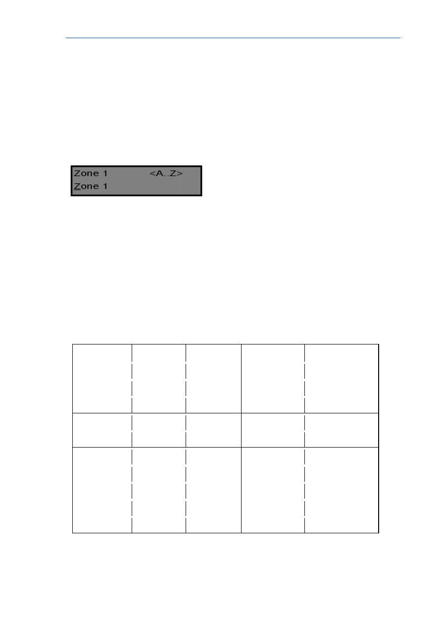
RUNNER - Installation & Config. Guide
41
to show the status of the first Area when armed. The second position (in this case the “B”) is
the identifier used to show the status of the second Area.
If you preferred to have the first area shown as Area “1” and not “A” then you can change it
here using the same method as used previously. With the cursor underneath the letter “A”,
Press the “1” button four times until the character in the first slot shows “1”.
When you are happy with the changes Press the <ENTER> button to save the changes.
Changing the Zone Names
When in “Local Edit Program Mode” and you have entered {PROG}-[1]-[ENTER], the display
will look like this;
The Cursor will be underneath the first letter to be edited (in this case the “Z”).
The letters <A..Z> indicate that the letters selected by the numeric buttons (0-9) will be in
capitals.
By pressing the “MEM (CROW)” button once, the display will change to <a..z> indicating
that the letters selected by the numeric buttons (0-9) will be lower case.
By pressing the “MEM (CROW)” button again, the display will change to <
ד
..
ג
> indicating
that Hebrew characters can be selected by the numeric buttons (0-9).
You can cycle back to another selection by pressing the “ (CROW)” button.
Once you have selected the desired font you can now proceed to change the text for Zone 1.
The following table shows the English Characters that can be selected by each numeric
button.
The lower case options are shown in ( )
▼Button #
1st Press
2nd Press
3rd Press
4th Press
1
* (‘)
# (<)
= (>)
1
2
A (a)
B (b)
C (c)
2
3
D (d)
E (e)
F (f)
3
4
G (g)
H (h)
I (i)
4
5
J (j)
K (k)
L (l)
5
6
M (m)
N (n)
O (o)
6
7
P (p)
Q (q)
R (r)
7
8
S (s)
T (t)
U (u)
8
9
V (v)
W (w)
X (x)
9
0
Blank
Y (y)
Z (z)
0
There are four different selections per button. By pressing the button once, a character will
appear in the display (see “1st press” column below) . Pressing the same button again will
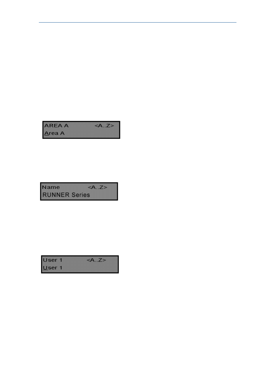
RUNNER - Installation & Config. Guide
42
cause the display to change to the next character in the sequence (see “2nd press” column).
After you have pressed the same button four times the next press (5th) will cause the
display to wrap back to the beginning.
Once you have selected the first character, Press the “BYPASS (CROW)” button to move
the cursor one position to the right.
Now select the second character and move the cursor to the right repeating the process until
all of the text is completed (Remember that there are a maximum of 16 characters per
program address).
If you make a mistake use the “STAY (CROW)” button to move the cursor towards the left
and make any corrections.
When you are happy with the text Press “ENTER” to save the changes. You can program the
text for all zones in the same way.
Changing the Keypad Area Name
When you enter [PROG]-[2001]-[ENTER] the display will look like the example above. You may edit the
Area Name at this location. The area name can be up to 16 characters long. If you program in a name for
the area, this name will appear when displaying events in memory display mode.
When you are happy with the changes Press the “ENTER” button to save the changes.
Changing the Keypad Name
When you enter [PROG]-[999]-[ENTER] the display will look like the example above. You may enter any
name you wish up to 16 characters in length (using the same method as described for zone names). This
name is displayed at the keypad in Idle mode.
When you are happy with the changes Press “ENTER” to save.
Changing the User Names
When in “Local Edit Program Mode” and you have entered {PROG}-[1001]-[ENTER], the display will look
like this;
You can now enter in the persons name (maximum of 16 characters). When viewing events in “Memory”
mode, the User name will appear to identify who the user was that Armed/Disarmed the system.
When you are happy with the changes Press <ENTER> to save.
Changing the Output Names
When in “Local Edit Program Mode” and you have entered [PROG]-[3001]-[ENTER], the display will look
like this;

RUNNER - Installation & Config. Guide
43
You can now enter an Output name (maximum of 16 characters). When viewing events in
“Memory” mode, the Output name will appear to identify what function the Output is
controlling.
When you are happy with the changes Press “ENTER” to save.
Resetting Individual Text to Default or Last Saved Setting
While in “Local Edit Mode” there are two special functions that can be performed at any of
the “Local Edit” Program locations. They are “Return to Default Text” or “Return to
Previously Saved Text”.
For Example, to Return the Zone 1 text back to Defaults;
If during the programming of Zone 1 text [PROG]-[1]-[ENTER] you wished to return back to
the default text, simply Press and hold the “B” button for 2 seconds, and the text will return
to the default settings.
If you wished to return to the last saved version of the text simply Press and hold the “A”
button for 2 seconds and the last saved text for zone one will appear.
NOTE: If the last saved version of text for Zone 1 was in fact the default setting, then
pressing “Control” then “1” or “A” will return the default text anyway.
Resetting All Text to Default
While in “Local Edit Mode” it is possible to restore all of the customisable text fields to the
factory default settings.
When you enter in [PROG]-[801]-[ENTER] display will prompt you to press [801]-
[ENTER] again. Once you have pressed “801 enter”, all customisable text (for example,
zone names, user names, output names, etc) will be returned to the default text.
Copying Text to Another LCD Keypad
If more than one LCD keypad is connected to the panel, it is possible to copy the edited Text
from one LCD keypad to all other LCD keypads connected to the same panel.
When you enter in [PROG]-[800]-[ENTER], all of the customisable text at the keypad will
be transferred to all other LCD keypads connected to the control panel.
There is also an alternative method to transfer the text. Pressing the “CHIME” button for 2
seconds while in “Local Edit Mode” will perform the transfer. The text in your keypad will be
transferred to all other LCD keypads connected to the panel.
Exiting Local Edit Program Mode
Press and hold the <PROGRAM> button for 2 seconds and the LCD keypad will leave Local
Edit Mode and return to Idle Mode or; Press the <PROGRAM> button repeatedly until the display
reads “Exit Programming”, then press the <ENTER> button to exit program mode.

44
Program Mode Access
Accessing Program Mode
How to Program Using Led Keypads
The programming sequence follows this pattern;
<PROGRAM> - <1,2 or 3 digit address> - <ENTER>
(Program Address)
1 short beep if OK - 1 long beep if error, THEN
<PROGRAM> - <1,2 or 3 digit sub-address> - <ENTER>
(Sub-Address)
3 short beeps if OK - 1 long beep if error
The LED’s will display current value or status
Enter the new value or option
<New Value> - <ENTER>
3 short beeps if OK - 1 long beep if error
Throughout this manual you will see program instructions expressed as
P 1 E 1-100 E
Using the above example the <P> represents the PROGRAM key and <E> represents the
ENTER key.
<1> refers to the address for programming User Codes and <1-100> refers to Users 1-100.
Access to Programming on Power Up (Installer Mode)
When power is applied to the controller for the first time and with the panel tamper input
open, the panel will inhibit tamper alarms and ready the panel to enter INSTALLER
PROGRAM MODE (unless the Installer Lock-out at address P25E10E Option 8 has previously
been enabled). At this point you can go to any keypad which is connected to the panel and
press <PROGRAM> <ENTER> which will automatically put that keypad into full Program
mode. The Program LED will now be Flashing (NOTE: Only one keypad can be in Program
mode at any time).
Access to Installer Program Mode from Run Mode
Before you can enter Installer program mode from normal operating mode, the panel must
not be Armed or in Stay mode. Program mode access is inhibited if any part of the system is
Armed.
Press <PROGRAM> - <Installer Code> - <ENTER>
Program light will Flash
Note: Default Installer Code (P25E1E) is 000000.
You are now in Installer Program Mode. Any program addresses may be viewed or changed
in this mode.
ACCESS TO CLIENT PROGRAM MODE FROM RUN MODE
Press <PROGRAM> - <Master User Code> - <ENTER>
Program light On Steady

RUNNER - Installation & Config. Guide
45
Note: Default Master User Code is code # 1 (P1E1E) which is 1234.
You are now in Client Program Mode. Access to certain program locations is limited while in
Client mode (see the options at address P5E). Each User can have different privileges based
on the options assigned to the User at address P5E. If no options are set at address P5E for
a user, they will not be allowed access to Client program Mode.
Resetting To Factory Default Settings
(From Install Mode Only)
There are two addresses that allow you to reset the panel back to the factory defaults. The
first resets just User Codes, Installer Code & Telephone Numbers. The Second resets all
programming back to the factory Defaults.
e.g. To reset All System defaults:
Press <PROGRAM> - <P200E10E> - <ENTER>
3 short beeps if OK - 1 long beep if error
After the system configuration has been reset back to defaults, all values, options & Codes
will be set to the values shown in the Program Summary as defaults. These values have
been chosen as the most common set-up for the majority of systems.
To reset partial defaults:
Press <PROGRAM> - <P200E9E> - <ENTER>
3 short beeps if OK - 1 long beep if error
The partial reset to defaults will return all User Codes, the Installer Code and Telephone
Numbers back to the values shown in the Program Summary as defaults. These values have
been chosen as the most common set-up for the majority of systems.
Exiting Program Mode
To Exit Program Modes Using Led Keypad
To exit either program mode when you have finished programming:
Press <PROGRAM> - <ENTER>
Program light goes out
The panel is now back in Run Mode, any program changes you have made will have replaced
previous values and be in effect.
Note: During programming Tampers and 24 hour alarms are disabled which allows quiet
access to the panel, detectors and external siren units, etc. On exiting program mode, all
inputs are scanned and if any tampers or 24Hr alarms are present an activation will occur.
To Exit Program Modes Using LCD Keypad
There are two ways to exit Program Mode with an LCD keypad. To exit either program mode
when you have finished programming:
Repeatedly press the <PROGRAM> button until the display shows
“<ENTER> TO EXIT”.
Now press <ENTER> to exit Program Mode.
OR
Press and hold the <PROGRAM> button for 2 seconds to exit program mode.
The panel is now back in Run Mode, any program changes you have made will have replaced
previous values and be in effect.
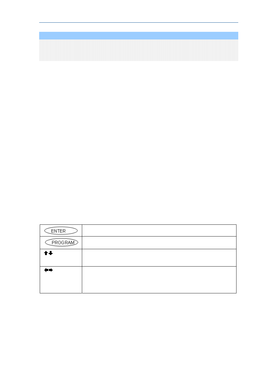
RUNNER - Installation & Config. Guide
46
NOTE
During programming Tampers and 24 hour alarms are disabled which allows
quiet access to the panel, detectors and external siren units, etc. On exiting
program mode, all inputs are scanned and if any tampers or 24Hr alarms are
present an activation will occur..
How to Program Using LCD Keypads
Access to Program Mode when using an LCD Keypad is exactly the same as when using an
LED Keypad (see previous page for access to program mode from power-up and normal run
mode).
Once in Program Mode (either Client Mode or Installer Mode), the User can still enter
program addresses directly at the keypad to go straight to a particular address, as with the
LED Keypad.
But the LCD Keypad also incorporates built-in menus that allow the Programmer to move
through the Main-Menus using the Up/Down Arrow keys. Also when at a data entry location,
the Left/Right Arrows can be used. These special Function Arrow keys are clearly marked on
the keypad buttons (the position of the buttons can vary depending on the type of LCD
Keypad installed).
When navigating the Menus using the Arrow keys, each button has a special function
depending on where you are within the menus.
When you enter program mode the LCD Keypad display automatically defaults to
“CLIENT:USER” (if in Client mode) or “INSTALLER:USER” (if in Installer mode). By using the
UP or DOWN Arrows, the user can cycle through all of the available menus.
The menus are accessed in a particular order based on the most frequently used program
locations. All of the Main and the Sub-Menus are shown on the following pages.
LCD Program Menu
LCD Keypad Menu Programming
The LCD Keypad enables “Manual Free’ programming of the Runner 8/16 panel. Easy to
follow plain text Menus will be displayed on the keypad to enable selection of the desired
programming options.
<ENTER> key selects the Menu you wish to work in or the option in a
Sub-Menu you wish to use.
<PROGRAM> key will step you back to the previous Menu level
<Up> or <Down> arrow keys will allow you to cycle through the Menu
options (Main & Sub Menus).
<Left> or <Right> arrow keys can be used when in the Data Entry-Menus
to cycle through the options
(eg if in “USERS” Data Entry-Menu, the
options would be Users 1-100, if in “ZONES” the options would Zones 1-16,
etc)

RUNNER - Installation & Config. Guide
47
Selecting the Main-Menu Headings
(“ Up” Or “ Down” Arrow Keys)
Enter “INSTALLER” Program Mode eg <PROGRAM> - <INSTALLER CODE (000000)> -
<ENTER>.
The LCD will display “INSTALLER:USERS”. This is the default Main-Menu heading.
To access a desired program location you first navigate to the desired Main-Menu by using
the “ Up” or “ Down” arrow keys on the keypad. Each press of “ Up” or “ Down” arrow
keys will advance the display to the next Menu heading.
The Main-Menu headings are shown on the top line of the LCD display.
To access the Sub-Menu options from a Main-Menu press the <ENTER> button.
Selecting the Sub-Menu Headings
(“ Up” Or “ Down” Arrow Keys)
Having pressed the <ENTER> button at the selected Main-Menu heading the keypad will now
show Sub-Menus for that heading.
The Main-Menu heading will remain on the top line of the LCD display and the Sub-Menus
will appear on the bottom line.
Each press of “ Up” or “ Down” arrow keys will advance the Sub-Menus displayed on the
bottom line either up or down by one location..
To access the Data Entry-Menu options from the Sub-Menu press the <ENTER> button.
Selecting the Data Entry-Menu Headings
Having pressed the <ENTER> button at the desired Sub-Menu heading, the keypad will now
be in the Data Entry-Mode.
The Main-Menu heading on the top line of the display will be replaced with the actual data
entry field description, e.g. if you had gone from “USERS” to “CODES” then to the data entry
field of codes the display will show “USER CODE 1” on the top line of the display and the
code “1234” on the bottom line (“1234” being the default User 1 code). See the chart on
page 48 for details.
You can now change the code, e.g. to change Code # 1 to 4567 press <4567> <ENTER>.
The bottom line will now show the new code of “4567”.
At this point you can use the “ Up” or “ Down” arrow keys to cycle through the other
Sub-Menu options for User Code 1 to program all of the options for code 1, or;
You can use the “Left” or “Right” arrow keys to cycle through all of the User codes. This
allows you to program all of the user codes from 1-100. The “ Right” arrow key when
pressed will take you up one User at a time and the “Left” arrow key will take you down
one User, e.g. if the display was currently showing “USER CODE 10”, pressing the “ Left”
arrow key will take the display to “USER CODE 9”, pressing the “ Right” arrow key will take
the display to “USER CODE 11”.
You can also use the “ Left” or “ Right” arrow keys to move through all of the User codes,
and while at a particular User, you can also use the “ Up” or “ Down” arrow keys to
program all options for that User.
If you are at a location that has 8 programmable options, e.g. P4E where the User
Arm/Disarm options can be set, by pressing and holding the <CONTROL> button then within
2 seconds pressing the <ENTER> button you can access the sub- text that describes what
each option can do. To exit the sub-text display press <ENTER>.
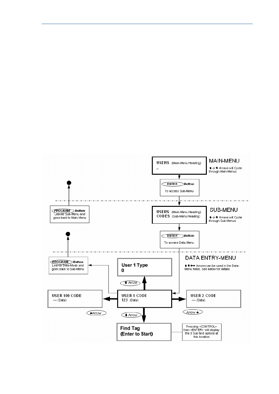
RUNNER - Installation & Config. Guide
48
Stepping Back Through the Menus
If you are in a Menu location, eg. the “USER” Data Entry field, and you wish to step back one
stage to the previous Sub-Menu, you need to press the <PROGRAM> button.
Each time the <PROGRAM> button is pressed the display will step back to the previous stage
(remembering where you were before) until you get back to the Main-Menu.
For example if you were in the “KEYPADS” Main-Menu, then pressed <ENTER> to get to the
“AREAS” Sub-Menu for keypads, then pressed <ENTER> again to get to the “AREAS” Data
Entry-Menu for keypads, you could now press the <PROGRAM> button once and it would
take you back to the “KEYPADS/AREAS” Sub-Menu. Pressing <PROGRAM> again will take
you
back to the “KEYPADS” Main-Menu, and pressing <PROGRAM> one more time will
return you back to the default “USERS” Main-Menu.
If you get back to the “USERS” menu and press the <PROGRAM> button once more the
display will go to the
program exit menu. If you press <ENTER> when at this point the panel will leave program
mode. If you don’t wish to leave program mode you can press the <PROGRAM> button
again to return to the “USERS” menu.
The flowchart below indicates the program menu steps using the “ARROW” , “ENTER” &
“PROGRAM” Buttons on the keypad.
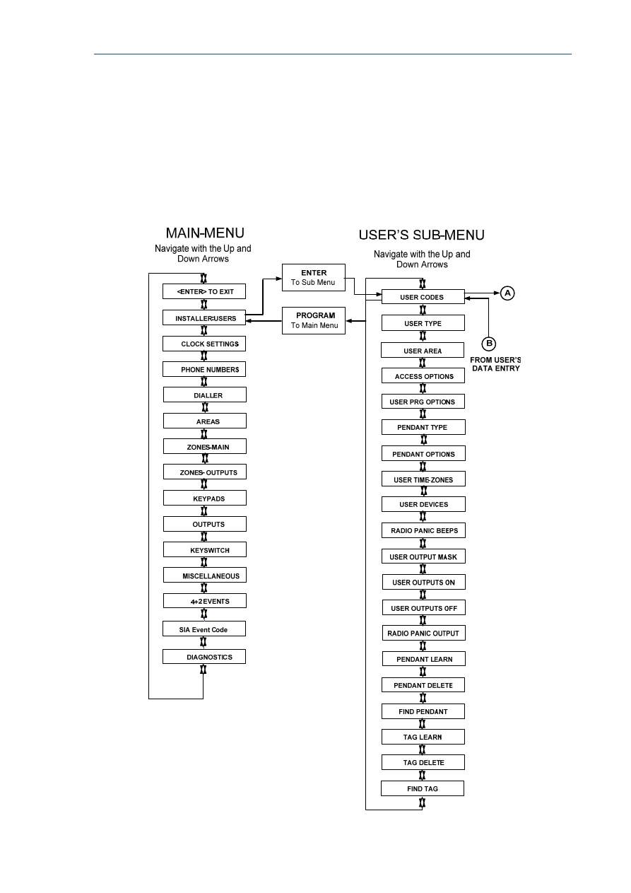
RUNNER - Installation & Config. Guide
49
LCD Keypad Program Menu Flowchart
There are two Menu navigating options when in the Program-Data Menus. Using the “Users”
examples shown below.
1. If the “Up” or “Down” Arrows are used, the Menus will cycle through the different
Sub-Menus for a particular User. See User’s Data-Entry I.
2. If the “Left” or “Right” Arrows are used, the Menus will cycle through all of the
individual Users. See User’s Data-Entry II.
Users are shown as the example on this page but the same properties apply to Zones, Areas,
Outputs, etc, when programming with the LCD Keypad
.
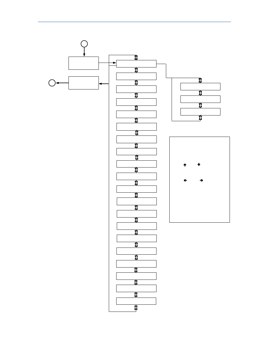
RUNNER - Installation & Config. Guide
50
USER’S DATA-ENTRY I
Navigate with the Up and
Down Arrows
USER 1 USER TYPE
USER 1 USER CODES
ENTER
PROGRAM
To Sub Menu
To Data Menu
FROM USER’S
SUB-MENU
B
A
TO USER’S
SUB-MENU
There are two Menu
navigating options when in the Program-
Data Menus.
Using the “Users” examples shown on
this page;
1) If the “ Up” or “ Down” Arrows are
used, the Menus will cycle through the
different Sub-Menus for a particular
User. See User’s Data-Entry I.
2) If the “ Left” or “ Right” Arrows
are used, the Menus will cycle through all
of the individual Users.
See User’s Data-Entry II.
Users are shown as the
example on this page but the same
properties apply to Zones, Areas,
Outputs, etc, when programming with the
LCD Keypad
.
USERS DATA-ENTRY II
Navigate with the Up and
Down Arrows
USER 1 ACCESS OPT
USER 1 USER TYPE
USER 1 USER CODES
USER 1 USER DEVICES
USER 1 USER TIME ZONES
-
USER 1 USER PRG OPT
USER 1 PENDANT TYPE
USER 1 PENDANT OPT
USER 1 RADIO PANIC BEEPS
USER 1 USER OUT ON
USER 1 USER OUT MASK
USER 1 ACCESS OPT
USER 1 RADIO PANIC OUT
USER 1 PENDANT LEARN
USER 1 USER OUT OFF
PENDANT DELETE
USER 1 TAG LEARN
USER 1 TAG DELETE
USER 1 FIND PENDANT
USER 1 FIND TAG
USER 1 USER AREA
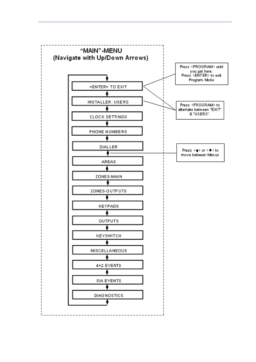
RUNNER - Installation & Config. Guide
51
LCD “Main” Menu Headings
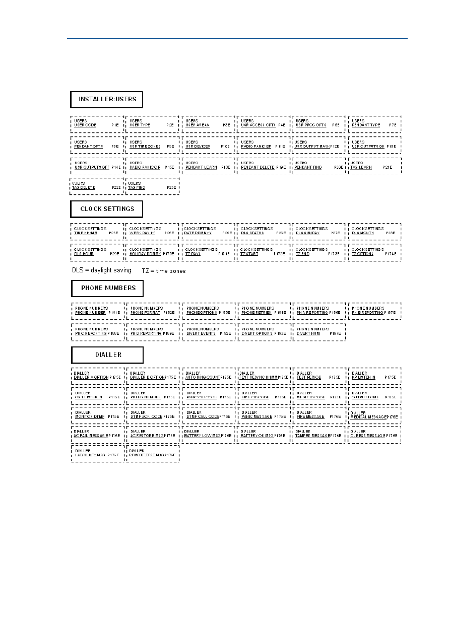
RUNNER - Installation & Config. Guide
52
LCD Keypad Main & Sub Menu Program Chart
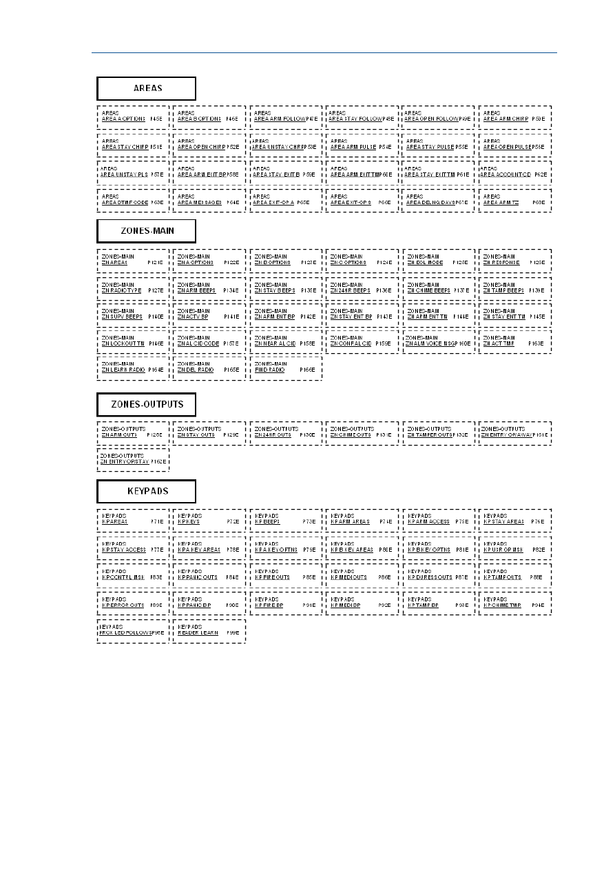
RUNNER - Installation & Config. Guide
53
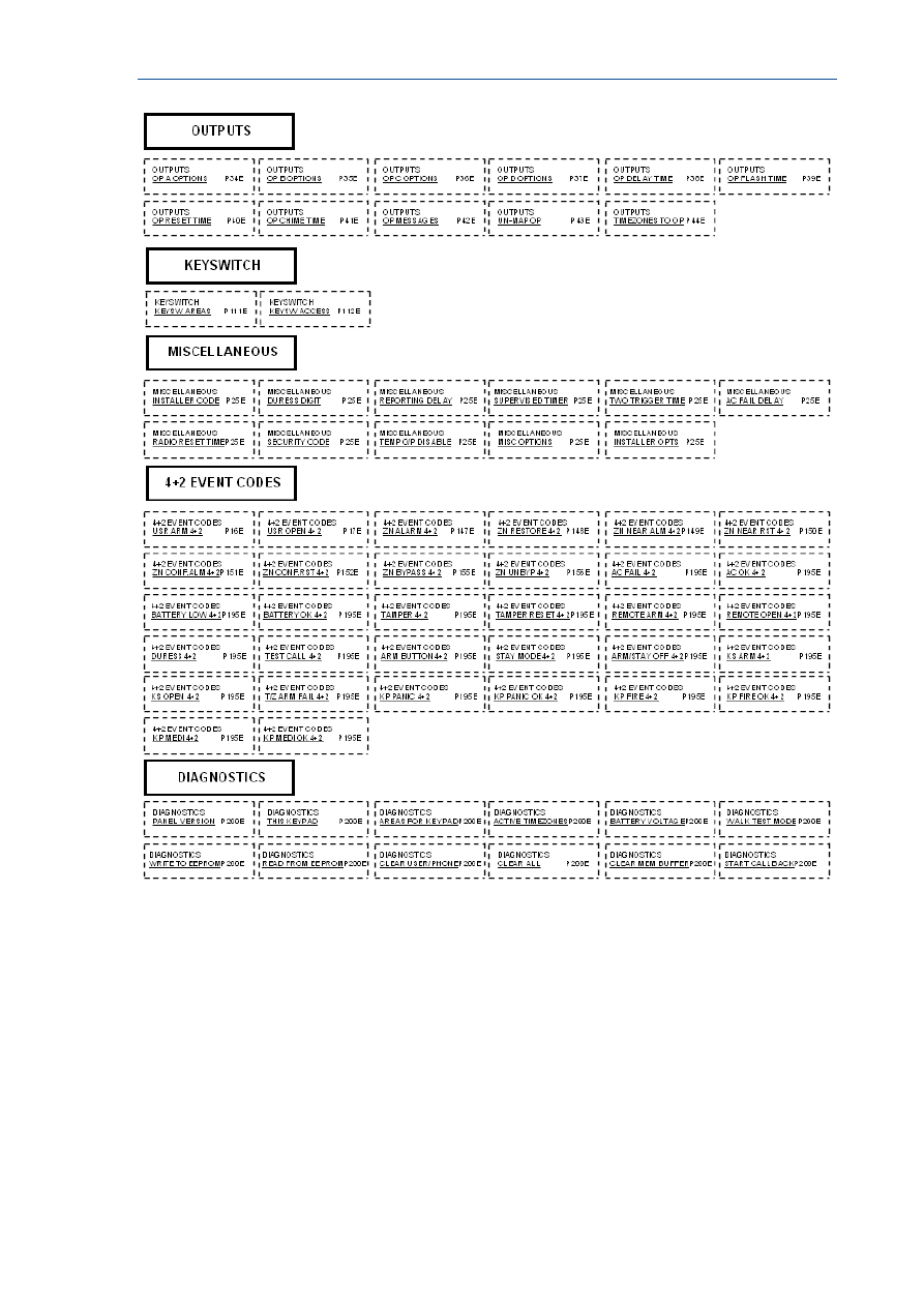
RUNNER - Installation & Config. Guide
54

55
Special Keypad Functions
Arming or Disarming Two Areas at a Keypad
If the panel is configured for two Areas “A&B”, and the option “ARM” button required before
code is turned on (P45E Option 1), there are a number of possible arming options.
If a user code is only assigned to one area and they press <ARM> <CODE> <ENTER> at the
keypad, only the Area assigned to their code will Arm.
If a user code is assigned to both areas but the keypad being used is only assigned to one
area, pressing <ARM> <CODE> <ENTER> will only arm the area assigned to the keypad.
If a user code is assigned to both areas and the keypad being used is also assigned to both
areas, pressing <ARM> <CODE> <ENTER> will put the keypad into a “Ready to Arm” state.
On the LCD keypad the display will show “Area/s to Arm” “A B”, and on the LED keypad
LED’s 1 & 2 (LED 1 = Area A & LED 2 = Area B) will turn on.
If you press the <ENTER> button now, both areas A&B will arm. If before pressing the enter
button you wish to deselect one of the Areas eg if you only want to arm area B press the
number “1” and Area “A” will disappear on the LCD keypad display or the number “1” will
turn off on the LED keypad indicating that only area B will arm when the enter button is
pressed.
The number “1” will toggle area A on/off and the number “2” will toggle area B on/off.
If you don’t do anything the panel will proceed with arming both areas after 10 seconds time
has elapsed.
On disarming, after entering <CODE> <ENTER> the display on the LCD keypad will show
“Area/s to Disarm” “A B”, and on the LED keypad LED’s 1 & 2. You can press the <ENTER>
button at this point to disarm both areas, select which area you wish to disarm by using the
numbers 1 & 2 on the keypad, or if you don’t do anything the panel will proceed with
disarming both areas after 10 seconds time has elapsed.
LCD Quick View Mode
If any zones are unsealed when disarmed the LCD keypad will scroll through each unsealed
zone displaying the 16 character name for each zone. If a number of zones are unsealed
simultaneously it can take sometime for the display to show all of the unsealed zones.
By pressing the <ENTER> button when zones are unsealed the keypad will enter the “Quick-
view” mode. When in “Quick-view” mode, each unsealed zone is displayed as a single two
digit number eg “01 05 10”. Up to 5 unsealed zones maybe displayed at one time. If more
than 5 zones are unsealed at the time the display will scroll to the next bank of 5 zones so
the user can see quickly which zones are unsealed. To exit “Quick-view” mode you simply
press the <ENTER> button again or the keypad will time out automatically in approximately
30 seconds.

RUNNER - Installation & Config. Guide
56
Toggle Chime Mode On/Off
On the Crow LCD Keypad there is a “CHIME” button. Pressing and holding that button for
two seconds will toggle Chime Mode from On-Off or Off-On.
Send Manual Test Call
If the panel is configured for Contact ID reporting and test calls are programmed to report,
you can force a manual test call by pressing and holding <CONTROL> followed within 2
seconds by <0>. This will cause a manual test call to be sent to the monitoring company.
You can also dial into the panel from a remote site and using the telephone cause a manual
test call remotely. See P175E15E and P176E11E for details.
Manually Answer an Incoming Call
If the panel is not configured to answer in-coming calls, the user can force it to answer the
call by pressing and holding <CONTROL> followed within 2 seconds by <9>. This will make
the panel answer the call immediately. For this function to work the phone line must be
ringing at the time and there must have been at least two rings before pressing the buttons.

57
Programming Users
User Codes
P1E 1-100E (NOTE: Users 21-100 can be Radio Users)
Adding or changing a User Code
Up to 100 codes can be programmed into the panel. The user codes are located in address
P1E 1-100E.
By default, Code 1 has Master Code permissions and must be used to enter Client program
mode.
Codes 1-100 may be varied in length from 1 to 6 digits (unless option 8 at P25E11E is on
then the codes must be between 4-6 digits long).
To program a User Code you must first be in client or installer program mode, then select
the address P1E followed by the User Number you wish to program e.g. 1-100E (If there is
already a code programmed at this address, it will be displayed back to you) Now enter the
code then press the <ENTER> key.
eg. P1E2E 2580 E
3 beeps - program light on solid or flashing
In this example we have programmed Code 2 to be 2580.
eg. P1E5E 9876 E
3 beeps - program light on solid or flashing
In this example we have programmed code 5 to be 9876
To replace a code simply enter the new code in the same address as the old code. This will
overwrite the previous code but maintain the user permissions as mapped to that user
number.
NOTE: When displaying User Codes on an LED keypad, digits 1-9 use the zone indicators 1-
9. The digit 0 is indicated by the "AUX” light.
Removing a User Code
To remove or delete a code simply press the <BYPASS> button after entering the code
address when using an LED keypad, or press and hold the <CONTROL> button then within 2
seconds press the <0> button if using an LCD keypad.
e.g. LED Keypad press P1E3E <BYPASS> E
3 beeps - Program light on solid or flashing
User Code # 3 Erased
e.g. LCD Keypad press P1E3E <CONTROL> then <0>
3 beeps
User Code # 3 Erased

RUNNER - Installation & Config. Guide
58
User Code Type
USER CODE TYPE - P2E 1-100E (NOTE: only Users 21-100 can be Radio Users)
Option 0 - Keypad Code User {PIN}
Option 1 - Radio user (User 21-100 only)
Option 2 - Access Tag/Card User
Option 3 - Both Code and Access Tag/Card User {Tag + PIN}
Option 4 - Either Code or Access Tag/Card User {Tag or PIN}
Option 0
Keypad Code User {PIN} - All 100 Users can be 1-6 digit code Users if required.
Codes can be used to Arm/Disarm all or part of the alarm or they can be used to
operate outputs for access control purposes. Users can be assigned to keypads and
so can outputs so that a User assigned to multiple outputs (which can in turn be
linked to doors) can operate only the door assigned to the keypad they are using.
Option 1
Radio User - Users 21-100 can be Radio keys (Pendant) if required. Radio keys can
be used to Arm/Disarm all or part of the alarm or they can operate outputs directly.
Unlike user codes, a radio key cannot be assigned to a keypad so if a radio key is
assigned to more than one output and the radio key is operated, all of the outputs
assigned to the radio key will turn on.
Option 2
Access Tag/Card User - Users 1-100 can be Access Tags or Cards if required.
Access Tag or Card operation requires that the optional Proximity Reader is connected
to the panel. The Proximity Readers can be assigned to any one of the 8 possible
keypad addresses. Access tag or Card Users can be used to Arm/Disarm all or part of
the alarm or they can be used to operate outputs for access control purposes. Access
Tags or Cards can be assigned to a keypad address and so can outputs so that an
Access User assigned to multiple outputs (which can in turn be linked to doors) can
operate only the door assigned to the keypad address they are using.
Option 3
Both Code and Access Tag/Card User {Tag + PIN} - Up to 100 code Users and
up 100 tag or card Users can be stored in the panel. If the Proximity Reader with the
full keypad is installed on the panel, it is possible to arm/disarm the alarm or gain
access through a door by presenting the tag/card at the reader then entering in the
user code {PIN Number}. It MUST be in that order ie Tag then PIN. This option
provides a more secure means of arming or disarming the alarm, or gaining access
through a door, because it requires both the access tag/card plus the PIN number.
Option 4
Either Code or Access Tag/Card User {Tag or PIN} - Up to 100 code Users and
up 100 tag or card Users can be stored in the panel. If the Proximity Reader with the
full keypad is installed on the panel, it is possible to arm/disarm the alarm or gain
access through a door by entering in the user code at the reader or presenting the
tag/card at the reader. This option gives two methods of controlling the alarm.
User Areas
USER AREAS - P3E 1-100E
Option 1 - Assigned to Area A
Option 2 - Assigned to Area B
Option 1
Assigned to Area A - If a User has option 1 on, they can Arm/Disarm all zones
assigned to Area A
Option 2
Assigned to Area B - If a User has option 2 on, they can Arm/Disarm all zones
assigned to Area B

RUNNER - Installation & Config. Guide
59
User Access Options
USER ACCESS OPTIONS - P4E 1-100E
Option 1 - User can Arm Area
Option 2 - User can Arm Stay Area
Option 3 - User can Disarm Area
Option 4 - User can Disarm Stay Area
Option 5 - User is a Security Guard User
Option 6 - User will Arm Latchkey Mode
Option 7 - User can set Call Divert Mode on Arm/Disarm
Option 8 -
User can View Event Memory
Option 1
User can Arm Area - If a User has option 1 on, they can Arm all Areas assigned at
location P3E.
Option 2
User can Arm Stay Area - If a User has option 2 on, they can Arm Stay Mode for all
Areas assigned at location P3E.
Option 3
User can Disarm Area - If a User has option 3 on, they can Disarm all Areas
assigned at location P3E.
Option 4
User can Disarm Stay Area - If a User has option 4 on, they can Disarm Stay Mode
for all Areas assigned at location P3E.
Option 5
User is a Security Guard User - If a User has option 5 on, they can Arm all Areas
assigned at location P3E, but they may only Disarm if the panel is currently Armed
and in the alarm state.
Option 6
User will Arm Latchkey Mode - If this option is on, the User will Arm the alarm in
Latchkey Mode. Latchkey Mode can also be armed by using the <ARM>, <STAY>,
<A> or <B>, (see P75E, P77E, P79E & P81E option 6) or the key-switch (see P112E
option 6). If a User with this option on Disarms the alarm no Disarm report will be
sent via the dialler. If Latchkey Mode is Armed and a user with this option off Disarms
the alarm a disarm report will be sent to alert parents when their children have
returned home. Reporting of Latchkey Disarm is enabled at location (P189E option 1).
If a Voice report is desired the message is assigned at P176E10E. Normally you would
select a telephone number/s set for domestic or voice reporting to report the
Latchkey disarm signal.
Option 7
User can set Call Divert Mode on Arm/Disarm - If a User has option 7 on, they
can initiate the Call Divert Number/s to be dialled on Arm/Disarm. This allows
automatic call diversion when the alarm is Armed and taking the diversion off when
Disarmed. Call divert must also be programmed (P192-194E).
Option 8
User can View Event Memory - If access to memory mode is restricted by turning on
option 8 at location P25E13E, this option allows the user to access memory mode by
pressing <MEMORY> <CODE #> <ENTER>. If this option is off and memory access is
restricted, the user cannot view memory mode.

RUNNER - Installation & Config. Guide
60
User Code Privileges - user program options
USER CODE PRIVILEGES - P5E 1-100E
Option 1 - User can Change Their Code
Option 2 - User can Change All Codes
Option 3 - User can Allow Access to Installer Mode/Edit All Codes
Option 4 - User can Change Telephone Numbers
Option 5 - User can Change Clock Settings
Option 6 - User can Change DTMF Codes
Option 7 - User can Learn New Radio Devices
Option 8 - User can Force a Download to the Call-back Number
Option 1
User can Change Their Code - If a User has option 1 on, they can access Client
Program Mode and change their code number.
Option 2
User can Change All Codes - If a User has option 2 on, they can access Client
Program Mode and change All User code numbers.
Option 3
User can Allow access to Installer Mode/Edit All Codes - If a User has option 3
on, they can access Client program Mode. From there an Installer with the correct
Installer Code can access Installer Program Mode. The User with this option can also
edit all User Codes and associated parameters as shown in the chart on page 139.
Option 4
User can Change Telephone Numbers - If a User has option 4 on, they can access
Client Program Mode and change the telephone and call divert numbers.
Option 5
User can Change Clock Settings - If a User has option 5 on, they can access Client
Program Mode and change the Time & date settings as well as daylight saving sart
and finish times.
Option 6
User can Change DTMF Codes - If a User has option 6 on, they can access Client
Program Mode and change the DTMF Codes. A DTMF Code can be used to remotely
Arm/Disarm an Area, turn Output/s On/Off or Acknowledge a Voice/Domestic alarm.
Option 7
User can Learn New Radio Devices - If a User has option 7 on, they can access
Client Program Mode and Learn a new Radio Key or Wireless Zone Device. They can
also remove radio devices or find what location number a device is stored at.
Option 8
User can Force a Download to the Call-back Number - If a User has option 8 on,
they can access Client Program Mode and force a PC connection to a pre-defined call-
back number. They can either enter in P200E12E or if using an LCD keypad go to the
“Diagnostics” Menu and select “Start Callback”.
Radio User Type - pendant type
RADIO USER TYPE - P7E 21-100E (NOTE: only Users 21-100 can be Radio Users)
Option 0 - Generic (General Pendant Type)
Option 1 - Crow Pendant
Option 21 - Ness Pendant
Option 0
Generic Type - If a Radio Pendant has no special functions and does not send a
battery low signal it is a Generic type 0.
Option 1
Crow Type - If a Crow Radio Pendant is being used set the type to 1. When the
pendant detects a battery low it will send a signal to the panel.
Option 21
Ness Type - If a Ness Radio Pendant is being used set the type to 21. When
the pendant detects a battery low it will send a signal to the panel.

RUNNER - Installation & Config. Guide
61
Radio User Privileges – pendant options
RADIO USER PRIVILEGES - P8E 21-100E (NOTE: only Users 21-100 can be Radio Users)
Option 1 - Pendant can Disarm at All Times
Option 2 - Pendant will cause an Immediate Panic Alarm
Option 3 - Pendant will cause a Delayed Panic Alarm (1.5 sec)
Option 4 -
Pendant only works during entry delay
Option 5 -
This User is a dedicated Duress Code
Option 6 - Spare
Option 7 - Spare
Option 8 – Spare
Option 1
Pendant can Disarm at All Times - If a Radio Pendant has option 1 on, they can
Disarm the alarm at any time. If this option is off, the pendant cannot disarm if the
panel is in alarm state.
Option 2
Pendant will cause an Immediate Panic Alarm - If a Radio Pendant has option 2
on, a Panic Alarm will be generated immediately the button is pressed.
Option 3
Pendant will cause a Delayed Panic Alarm - If a Radio Pendant has option 3 on, a
Panic Alarm
will be generated if the button is pressed for longer that 1.5
seconds. If the button is released before the time expires, no Panic Alarm will be
generated.
Option 4
Pendant only works during entry delay - If a Radio Pendant has option 4 on, the
pendant can
only disarm the alarm during the entry delay time. This means that
authorised radio key users must enter the building and trigger the entry delay before
the can disarm the alarm.
Option 5
This User is a dedicated Duress Code - If a User Code has option 5 on (restricted to
Users 21- 100 only), this code should be used as a dedicated Duress code. It should
not be used for daily disarming of the alarm but used when disarming under Duress.
User Time Zone Assignments
Time Zone Assigned To a User - P9E 1-100E
Option 1 - User Controlled by Time Zone # 1
Option 2 - User Controlled by Time Zone # 2
Option 3 - User Controlled by Time Zone # 3
Option 4 - User Controlled by Time Zone # 4
Option 5 - User Controlled by Time Zone # 5
Option 6 - User Controlled by Time Zone # 6
Option 7 - User Controlled by Time Zone # 7
Option 8 - User Controlled by Time Zone # 8
There are up to 8 Time Zones that can be programmed into the panel. A Time Zone consists
of a Start and Stop time plus the Days of the Week that the Time Zone is active. By selecting
Options 1-8 (function turned on) to a particular User, that user will only operate if the Time
Zone assigned is active.
For example, if Time Zone #1 had a start time of 0800 and a stop time of 1700 and active
days of 2-6 (Monday-Friday), a User with Time Zone 1 assigned can only be used between
the hours of 0800-1700 from Monday to Friday. Outside these hours the User Code will not
operate.

RUNNER - Installation & Config. Guide
62
More than one Time Zone can be assigned to a User. Using the above example for TZ#1 and
now assuming Time Zone #2 is set to 0900-1200 on day 7 (Saturday), by assigning both
TZ1 & 2 to a User will now mean their code is active during weekdays from 0800-1700 plus
they are also able to use their code on Saturdays between the hours of 0900-1200.
If the time-zone has just been programmed and should currently be active you will have to
wait until the next minute expires before the panel will update the time-zone status. You can
see if the time-zone is active at location P200E4E.
User to Keypad Assignment – user devices
User to Keypad Assignment - P10E 1-100E
Option 1 - User will work at Keypad # 1
Option 2 - User will work at Keypad # 2
Option 3 - User will work at Keypad # 3
Option 4 - User will work at Keypad # 4
Option 5 - User will work at Keypad # 5
Option 6 - User will work at Keypad # 6
Option 7 - User will work at Keypad # 7
Option 8 - User will work at Keypad # 8
Any user can be assigned to only operate at certain Keypads. This option controls whether a
code or access tag User can Arm/Disarm from certain keypads. This option does not restrict
users from operating outputs from a particular keypad (this is done at locations P82E &
P83E).
Radio Pendant Panic Beeps to Keypad
Radio Pendant Panic Beeps to Keypad
P11E 21-100E (NOTE: only Users 21-100 can be Radio Users)
Option 1 - A Pendant Panic Alarm will Beep at Keypad # 1
Option 2 - A Pendant Panic Alarm will Beep at Keypad # 2
Option 3 - A Pendant Panic Alarm will Beep at Keypad # 3
Option 4 - A Pendant Panic Alarm will Beep at Keypad # 4
Option 5 - A Pendant Panic Alarm will Beep at Keypad # 5
Option 6 - A Pendant Panic Alarm will Beep at Keypad # 6
Option 7 - A Pendant Panic Alarm will Beep at Keypad # 7
Option 8 - A Pendant Panic Alarm will Beep at Keypad # 8
If a Radio Pendant is programmed to create a Panic Alarm (see P8E), when the Panic Alarm
is activated it can be silent or it can sound the keypad buzzer. Each keypad can be silent
during a Pendant Panic Alarm (option turned off) or can give an audible indication of the
Alarm (option turned on).
User to Output Mask
User to Output Mask - P12E 1-100E
Option 1 - User is Mapped to Output # 1
Option 2 - User is Mapped to Output # 2

RUNNER - Installation & Config. Guide
63
Option 3 - User is Mapped to Output # 3
Option 4 - User is Mapped to Output # 4
Option 5 - User is Mapped to Output # 5
Option 6 - User is Mapped to Output # 6
Option 7 - User is Mapped to Output # 7
Option 8 - User is Mapped to Output # 8
Any user can be allowed to only operate certain Outputs. This Function is mainly used for
access control purposes. If an Output is being used to open a door but a User does not have
access through that door, by not allowing the User to operate that Output access through
the door can be denied.
User Can Turn an Output ON and OFF
User Can Turn an Output ON
User Can Turn an Output On - P13E 1-100E
Option 1 - User can turn ON Output # 1
Option 2 - User can turn ON Output # 2
Option 3 - User can turn ON Output # 3
Option 4 - User can turn ON Output # 4
Option 5 - User can turn ON Output # 5
Option 6 - User can turn ON Output # 6
Option 7 - User can turn ON Output # 7
Option 8 - User can turn ON Output # 8
Any user can be allowed to turn an Output ON. This Function can be used to control external
devices via the panel keypad with a User assigned to that Output. Once an Output is turned
ON by a User, the Output can turn OFF again automatically if a reset time is assigned to the
Output, or it can be turned off by the same user or by a different user with the next program
location.
User Can Turn an Output OFF
User Can Turn an Output OFF - P14E 1-100E
Option 1 - User can turn OFF Output # 1
Option 2 - User can turn OFF Output # 2
Option 3 - User can turn OFF Output # 3
Option 4 - User can turn OFF Output # 4
Option 5 - User can turn OFF Output # 5
Option 6 - User can turn OFF Output # 6
Option 7 - User can turn OFF Output # 7
Option 8 - User can turn OFF Output # 8
Any user can be allowed to turn an Output OFF. This Function can be used to control
external devices via the panel keypad with a User assigned to that Output. Once an Output
is turned OFF by a User, the Output can be turned on by the same user or by a different user
with the previous program location.

RUNNER - Installation & Config. Guide
64
Radio Pendant Panic Alarm to Output
RADIO PENDANT PANIC ALARM to OUTPUT - P15E 21-100E (NOTE: only Users 21-100
can be Radio Users)
Option 1 - A Pendant Panic Alarm will Operate Output # 1
Option 2 - A Pendant Panic Alarm will Operate Output # 2
Option 3 - A Pendant Panic Alarm will Operate Output # 3
Option 4 - A Pendant Panic Alarm will Operate Output # 4
Option 5 - A Pendant Panic Alarm will Operate Output # 5
Option 6 - A Pendant Panic Alarm will Operate Output # 6
Option 7 - A Pendant Panic Alarm will Operate Output # 7
Option 8 - A Pendant Panic Alarm will Operate Output # 8
If a Radio Pendant is programmed to create a Panic Alarm (see P8E), when the Panic Alarm
is activated it can be silent or it can turn on an Output. This option would normally be used
to turn on any internal and/or external audible alarms connected to Outputs during a
Pendant Panic Alarm.
Learn Find and Delete Radio Key Codes and
Tags
Learn Radio Pendant Codes – pendant learn
LEARN RADIO PENDANT CODES - P18E 21-100E (NOTE: only Users 21-100 can be Radio
Pendants)
A Radio Pendant must be enrolled into the panel before it can be used.
To learn a Radio Pendant you must first have a compatible receiver connected to the panel
keypad buss. With the receiver connected and the panel in program mode, entering P18E
then the pendant number you wish to enrol, eg 21E for pendant 21, the keypad will start to
beep to indicate that learn mode has been started and the LED on the receiver will flash.
Now operate the pendant you wish to learn into User slot 21. Once the transmitted code has
been received by the panel and saved as pendant 21, the keypad will stop beeping and the
LED on the receiver will stop flashing.
When learning a new radio code the panel checks all possible locations (including radio
zones) before saving the new code to ensure that the code has not already been loaded into
another slot. If the code already exists, the keypad will indicate which slot the code is
already installed at. A number from 1-16 indicates a zone slot and a number from 21-100
indicates a user slot.
DELETE a RADIO PENDANT CODE
DELETE a RADIO PENDANT CODE - P19E 21-100E (NOTE: only Users 21-100 can be
Radio Pendants)
If you wish to delete a single Radio Pendant, pressing P19E then the User number while in
Program Mode will delete the stored code against that User, eg P19E 21E will remove the
code stored for User 21.
FIND a RADIO PENDANT LOCATION
FIND a RADIO PENDANT LOCATION - P20E 0E (NOTE: only Users 21-100 can be Radio
Pendants)

RUNNER - Installation & Config. Guide
65
If you have a Radio Pendant loaded into the panel but are unsure which location (User #),
pressing P20E (then 0E on an LED Keypad) while in Program Mode will start “Find” Mode.
There is no need to press 0E when using an LCD keypad because the keypad will give you
written prompts after entering P20E. The keypad will start to beep to indicate that “Find”
mode has been started and the LED on the Receiver will flash. Now press the Radio Pendant
button that you wish to find. If the Radio Pendant is in memory the keypad will display the
number (1-16 indicates a zone, and 21-100 indicates a user). The keypad will stop beeping
and the LED on the Receiver will stop flashing.

RUNNER - Installation & Config. Guide
66
LEARN ACCESS TAG/CARD CODES
LEARN ACCESS TAG/CARD CODES - P21E 1-100E
An Access Tag/Card must be enrolled into the panel before it can be used. The panel can
have up to 100 proximity tags (key-ring style card), or proximity cards loaded into the
system. The tags or cards are stored separately to the User Codes but they follow the
options of Users 1-100 programmed at locations P2E, P3E, P4E, P9E, P10E, P12E, P13E &
P14E. For example if user 11 is assigned to area A (P3E Option 1), and can arm/disarm the
alarm (P4E Options 1 & 3), then access Tag/Card number 11 will arm/disarm area A also.
To learn an Access Tag/Card you must first have a compatible proximity reader connected to
the panel keypad buss. With the reader connected and the panel in program mode, entering
P21E then the Access tag/card number you wish to enrol, eg 11E for Tag/Card number 11,
the keypad will start to beep to indicate that learn mode has been started. Now present the
Access Tag/card to the reader. Once the Tag/Card number has been received by the panel
and saved, the keypad will stop beeping to indicate learn mode has stopped.
When learning a new access Tag/Card the panel checks all possible locations before saving
the new code to ensure that the code has not already been loaded. If the tag or card already
exists, the panel will not terminate learn mode but instead it will continue looking for a new
tag or card to be presented. This allows a new tag or card to be learnt while existing tags or
cards may be in use on the system.
After learning the tag or card, before it will work you MUST select the appropriate option at
location P2E (options 2, 3 or 4 must be selected for the tag to work).
DELETE an ACCESS TAG/CARD CODE
DELETE an ACCESS TAG/CARD CODE - P22E 1-100E
If you wish to delete a single Access Tag or Card, pressing P22E then the User number while
in Program Mode will delete the stored code against that User, eg P22E 11E will remove the
tag or Card stored for User 11.
FIND an ACCESS TAG/CARD LOCATION
FIND an ACCESS TAG/CARD LOCATION - P23E 0E
If you have an Access Tag or Card loaded into the panel but are unsure which location (User
#), pressing P22E (then 0E on an LED Keypad) while in Program Mode will start “Find” Mode.
There is no need to press 0E when using an LCD keypad because the keypad will give you
written prompts after entering P22E. The keypad will start to beep to indicate that “Find”
mode has been started. Now present the Access Tag or Card you wish to find to a proximity
reader connected to the panel. If the Tag or Card is in memory the keypad will display the
number where the Tag or Card is stored (a number from 1-100). The keypad will stop
beeping once the memory location has been found.

67
Miscellaneous Panel & Clock
Settings
Installer Code
INSTALLER CODE - P25E 1E
This code is used to enter full Installer Program mode (Program LED flashing on LED
Keypad). The default installer code is 000000. This code can only be changed while in
Installer Program Mode. To enter your new installer code press P25E1E. The existing code
will displayed at the keypad (either each digit flashed out sequentially on an LED keypad or
shown on the bottom line of the LCD keypad). To change the code simply enter the digits of
the new code and it will replace the old one. The Installer Code must be between 4-6 digits
in length.
Duress Digit
DURESS DIGIT - P25E 2E (Value can be 1-9, 0 = Duress Disabled)
The duress digit can be a number from 1-9 (a value of “0” means the duress function is
disabled).
To create a duress alarm the duress digit must be entered before a valid user code (eg If the
code was “123” and the duress number was “4”, then entering a code of <4123> <ENTER>
would create a duress alarm).
Dial Reporting Delay
DIAL REPORTING DELAY - P25E 3E (0-255 Seconds)
If this address is set to 0, there will be no report delay. If it is set to any value other than 0
then a delay equal to the programmed value will stop the panel from reporting an alarm until
this delay time expires (both during the exit delay time if option 3 is on at P122E for a zone
or when an instant zone is triggered when fully armed). While the timer is active certain
outputs can be disabled at location P36E option 5. Once the timer has expired it will not start
again, the panel must be disarmed then armed to reset the timer.
Radio Zone Supervised Timer
SUPERVISED TIMER
RADIO ZONE SUPERVISED TIMER - P25E 4E (Value 0-9999 Minutes)
If a radio detector is capable of sending regular supervisory signals to the panel and the
zone type is set for “Supervised Signal Active”, this timer sets how long a period has to
elapse with no received transmissions before a supervisory failure alarm is generated.

RUNNER - Installation & Config. Guide
68
Two Trigger Timer
TWO TRIGGER TIMER - P25E 5E (0-255 Seconds)
If a zone is set to two trigger, the zone has to cause an alarm twice within the two trigger
time period to cause an alarm. If multiple zones are set to two trigger, an alarm will be
generated it two zones trigger once each within the two trigger time period. If a two trigger
zone goes into alarm but remains in alarm for longer than the two trigger time period (ie
detector failure or cable cut) an alarm will be generated.
Mains Fail Reporting Delay
AC Fail delay
MAINS FAIL REPORTING DELAY - P25E 6E (0-9999 Seconds)
If a Mains Failure occurs this timer delays the reporting of Mains Failure to a Monitoring
Station. If the mains power returns before the timer expires, then no report is sent. If Mains
Failure is assigned to an output, this delay must expire before the output will turn on.
Receiver Fail Delay/Timer
Radio Reset Time
RECEIVER FAIL DELAY - P25E 7E (0-9999 Seconds)
If supervised radio detectors are used, the receiver will be seeing regular transmissions.
Because of this, the panel can monitor receiver activity to check that the receiver is still
working. If the panel does not receive any signals within this time period a receiver failure
alarm will be generated. If set to 0, the receiver monitoring will be turned off.
Upload/Download Site Code Number
Security Code
UPLOAD/DOWNLOAD SITE CODE NUMBER - P25E 8E (8 characters)
The upload/download site code number must be entered if the panel is set for auto-answer
as this provides a security access level to the panel. The number can be up to 8 characters
in length. Valid characters for this number are 0-9,B-F. See chart on page 85 for details of
how to program the characters B-F.
Temporary Output Disable
TEMPORARY OUTPUT DISABLE - P25E 9E (Select output # 1-8)
This address allows a technician to select any output/s to be temporarily disabled for one
alarm or armed cycle, eg by selecting LEDS 1-4 (Outputs 1-4) at this location then leaving
program mode, outputs 1-4 will not turn on following any alarms. The technician is now free
to arm the system to test all monitoring signals without having any internal and/or external
alarms activating. When the alarm is reset or disarmed all outputs will now work normally
again.

RUNNER - Installation & Config. Guide
69
Miscellaneous Installer and Panel Options
MISCELLANEOUS PANEL OPTIONS - P25E 10E
Option 1 - Panel Tamper is 2k2 EOL
Option 2 - Direct access to program mode for the Installer Code
Option 3 - Disable Mains Fail Test
Option 4 - Listen-in to O/P # 1 Low Volume
Option 5 - Receiver Fail/RF Jammed Lockout
Option 6 - Send Output information to Keypad Buss
Option 7 - Cannot Arm if the System Battery is Low or AC has Failed
Option 8 - Installer Lockout
Option 1
Panel Tamper is 2k2 EOL - The Tamper input (Tmp) on the control panel requires
either a short circuit or a 2k2 End-of-Line resistor. If option 1 is on the panel must
see a 2k2 resistor (EOL) across the Tmp & 0V terminals to ensure the tamper is
sealed. If this option is turned off then a simple short circuit is all that is required to
seal the panel tamper.
Option 2
Direct access to program mode for the Installer Code - If this option is on, the
Installer Code can gain access to Installer Program Mode directly. If the option is
turned off, the installer can only gain access to Installer Program Mode via Client
Program Mode. This option allows the owner to control program mode access by the
installer. The User must have option 3 at location P5E turned on for them to allow
installer access.
Option 3
Disable Mains Fail Test - If the panel must be run off a DC supply or the Mains
supply can fail regularly, this option disables the mains voltage monitoring to prevent
mains fail alarms from occurring.
Option 4
Listen-in to O/P # 1 Low Volume - If Listen-In to Output 1 is turned on
(P175E8E), the level of sound from the speaker can be controlled with this option. If
this option is Off the sound level during listen-in to O/P 1 is high volume, turning this
option On makes the sound level low volume. For listen-in to Output 1 to work the
device connected to O/P 1 must be an 8Ώ speaker and the output must be modulated
(P35E1E Option 1 on). Failure to do this could result in damage to the speaker &
output.
Option 5
Receiver Fail/RF Jammed Lockout – If the receiver fail delay (P25E7E) is set to a
value other than 0 and the panel sees no activity from the receiver for the set period
of time, a receiver fail alarm will be generated. If this options is turned on, the panel
cannot be armed until the cause of the receiver failure has been resolved. Also if the
receiver detects a continuous signal for longer than 60 seconds it will send an RF
Jammed signal to the control panel. Under this alarm condition and if this option is
turned on, the control panel cannot be armed until the interference has been
removed.
Option 6
Send Output information to Keypad Buss - There is an optional 4 x relay output
expander board that can be connected to the keypad buss if required. For this output
expander to work option 6 must be turned on for the data to be sent on the keypad
buss to the expander.
Option 7
Cannot Arm if System battery is Low or AC has Failed – if this option is turned
ON, the panel cannot be armed if the panel battery is low or the AC has failed. When
the battery is fully charged or the AC has returned, the panel can then be armed. If
this option is turned off, the panel can be armed during these fault conditions.
Option 8
Installer Lockout - Normally if the panel is powered up with the panel tamper open
(ie system tamper alarm active) and in the Disarm state, then the panel will go into
installer program mode when the <PROGRAM> then <ENTER> buttons are pressed.
If this option is on, the panel will not allow access to program mode on power-up and
the only valid method of accessing program mode is via the installer code.

RUNNER - Installation & Config. Guide
70
INSTALLER OPTIONS
INSTALLER OPTIONS - P25E 11E
Option 1 - Entry to Installer Mode Resets Confirmed Alarms
Option 2 - Entry to Installer Mode Resets Tamper Alarms
Option 3 - Entry to Installer Mode Resets Low Battery Alarm
Option 4 - Entry to Installer Mode Resets Supervisory Alarms
Option 5 - Cannot Arm if there is a keypad Fault
Option 6 - Cannot Arm if there is a Telephone Line Failure or Comms Fault
Option 7 - 10 Incorrect Code Attempts locks out the keypad for 90 Seconds
Option 8 - User Codes Must be 4-6 digits long
Option 1
Entry to Installer Mode Resets Confirmed Alarms - If this option is turned on
and a Confirmed alarm has occurred, the alarm cannot be re-armed until the Installer
has reset the alarm. The Installer must access Installer Program Mode via Client
Mode to reset the system. The zones that caused the alarm will latch on (even when
disarmed) until reset by the installer to indicate that lockout is in effect.
Option 2
Entry to Installer Mode Resets Tamper Alarms - If this option is turned on and a
Tamper alarm has occurred (system or zone tampers), the alarm cannot be re-armed
until the Installer has reset the alarm. The Installer must access Installer Program
Mode via Client Mode to reset the system. The Trouble indication will latch on (even if
the tamper alarm has been cleared) until reset by the installer to indicate that
lockout is in effect.
Option 3
Entry to Installer Mode Resets Low Battery Alarm - If this option is turned on
and a Low Battery alarm has occurred, the Installer must access Installer Program
Mode via Client Mode to reset the battery low signal. If option 7 is turned on at
location P25E10E the alarm cannot be re-armed until the Installer has reset the
battery low signal.
Option 4
Entry to Installer Mode Resets Supervisory Alarms - If this option is turned on
and a Detector Supervisory alarm has occurred, the alarm cannot be re-armed until
the Installer has reset the alarm. The Installer must access Installer Program Mode
via Client Mode to reset the supervisory alarm.
Option 5 Cannot Arm if there is a keypad Fault – if this option is turned ON and a missing
keypad alarm is present, the panel cannot be armed until the keypad has been re-
installed.
Option 6 Cannot Arm if there is a Telephone Line Failure or Comms Fault – If this option
is turned on and the control panel has detected a telephone line fault or the dialler
failed to get kissed off (Comms Fault) following an alarm report the panel cannot be
armed. To reset the line failure the telephone line must be re-instated to allow
arming again. To reset the Comms Fault alarm, a user must access the memory.
Option 7 10 Incorrect Code Attempts locks out the keypad for 90 Seconds – If this
option is turned off the panel will create a keypad tamper alarm if more than 4
incorrect codes are entered at a keypad but the keypad will not be locked out. If this
option is turned on the panel will create a keypad tamper alarm if more than 10
incorrect codes are entered at a keypad and that keypad will then be locked out for
90 seconds.
Option 8
User Codes Must be 4-6 Digits - If this option is turned on, all User Codes must be
between 4-6 digits long. If it is turned off, the User Codes can be 1-6 digits long.
Hide User Codes - USER OPTIONS
USER OPTIONS - P25E 12E (NOTE: This Option can ONLY be accessed from Client Mode)
Option 1
Hide User Codes from Installer - This option is only accessible from Client
Program Mode. It is designed to allow the User (owner) of the alarm to hide their
User Codes from the Installer if desired. If this option is turned On, codes can only be

RUNNER - Installation & Config. Guide
71
changed or viewed in Client program mode. Users MUST have option 2 at location
P5E assigned before they can hide the user codes.
MISCELLANEOUS USER OPTIONS - P25E 13E
Option 1 - Code Required to View Memory
Option 2 - Cancel Handover Zone Function in Stay Mode
Option 3 - Output Control from Keypad is Disabled when Armed
Option 4 - Keypad Codes are Disabled During Entry Delay
Option 5 - No Keypad Indications while Armed
Option 6 - Monitored KP Buss Output Board
Option 7 – Enable Keypad Tamper
Option 8 - Limit Event & Dialer to 3 of any one type
Option 1
Code Required to View Memory - If this option is turned on, access to
Memory Mode will only be allowed by using an authorised code. The user must
press <MEMORY> <CODE #> <ENTER> to view memory mode. Codes are
authorised by turning on option 8 at location P4E. If this option is turned off
anyone can access memory mode.
Option 2
Cancel Handover Zone Function in Stay Mode - If this option is turned on,
any zone programmed with the handover feature will act as a normal delayed
zone during Stay mode (ie the handover feature will be ignored). The zone will
still have the normal handover feature during the full arm state.
Option 3
Output Control from Keypad is Disabled when Armed - If this option is
turned on any User code programmed to operate an output for access control will
be disabled when the area/s assigned to the user code is/are armed (P3E). If the
user code is assigned to area A but area B was armed the code can still operate
the output.
Option 4
Keypad Codes are Disabled During Entry Delay - If this option is turned on
no codes will operate during the entry delay. This forces the user to disarm
before entering the premises.
Option 5 No Keypad Indications while Armed - If this option is turned on and all areas
assigned to keypads are armed, the keypad display will be blank during the
armed state. If any keypad is assigned to areas A&B at location P71E, both areas
must be armed before the display will go blank on arming.
Option 6
Monitored KP Buss Output Board - This option performs a similar function to
option 6 at location P25E10E in that if it is turned on the Output status messages
are sent to the keypad buss. The difference with this option is when turned on
the panel is expecting the OUTPUTX4 board connected to the keypad buss to
acknowledge the messages. If the OUTPUTX4 does not acknowledge the output
status messages the panel will show an output board failure. This option should
only be turned on if an OUTPUTX4 board with the latest software is connected to
the keypad buss.
Option 7 Enable Keypad Tamper – if this option is turned ON the keypad tamper will be
enable and can cause to keypad tamper alarm if keypad removed from the wall.
If this option is OFF – the keypad tamper will be disabled, opening or removing
the keypad from the wall will not cause to tamper alarm on panel.
Option 8 Limit Events & Dialler to 3 of any one Type -
If this option is turned on the
panel will not record any more than 3 events in memory for any event type
during a single arm or disarm cycle, e.g. if the AC Failed 4 times while armed or
disarmed the panel will only record the AC fail 3 times in memory. And will only
report the AC fail 3 times to the dialler. As soon as the arm state has changed
any count are reset back to zero again. If this option is off there is no limit on
the recording and reporting of Events.

RUNNER - Installation & Config. Guide
72

RUNNER - Installation & Config. Guide
73
Setting Time, Date and Daylight Saving
Setting Real Time Clock
REAL TIME CLOCK HOUR/MINUTE -
P26E 1E (Value 0-2359)
REAL TIME CLOCK DAY of WEEK -
P26E 2E (Value 1-7) [where 1 =Sunday, 2 =
Monday, 3 = Tuesday, etc]
REAL TIME CLOCK DATE/MONTH/YEAR - P26E 3E (Value DDMMYY) for example
020904 = 2nd September, 2004
The Real Time Clock controls the Time-zones, the timing of automatic test calls and is used
to Time & Date stamp the events in the Event Buffer. Ensure this is set correctly at the time
of installation so that the all of the functions using the time have will work correctly. The
clock is programmed in 24 hour format (e.g. 00:00-23:59).
Daylight Saving (DLS) Settings
DAYLIGHT SAVING ACTIVE -
P26E 4E (If LED # 1 is On, Daylight Saving is currently
active)
NOTE: If you are in Daylight Saving Time when the alarm system is installed you MUST turn
on option 1 at location P26E 4E so that the panel knows that Daylight Saving Time is
currently active. Failure to do this will not allow the clock to automatically adjust to the
correct time when Daylight Saving Time Ends.
DAYLIGHT SAVING START SUNDAY -
P27E 1E (Value 0-5, 0= DLS Disabled)
DAYLIGHT SAVING END SUNDAY -
P27E 2E (Value 0-5, 0= DLS Disabled)
DAYLIGHT SAVING START MONTH -
P28E 1E (Value 1-12)
DAYLIGHT SAVING END MONTH -
P28E 2E (Value 1-12)
DAYLIGHT SAVING START HOUR -
P29E 1E (Value 0-23)
DAYLIGHT SAVING END HOUR -
P29E 2E (Value 0-23)
If Daylight Saving (DLS) is used, the actual start and stop details can be entered here and
the clock will automatically adjust for daylight saving.

74
Outputs
NOTE:
With all output programming options we refer to outputs 1-8. Only outputs 1-4 are available as
standard, with outputs 5-8 requiring the connection of the optional 4 way output expander
unit that connects to the keypad buss ( the output expander provides 4 change-over relay
contacts)
.
OUTPUT OPTIONS
OUTPUT OPTIONS “A”
OUTPUT OPTIONS “A” - P34E 1-8E
Option 1 - Invert Output
Option 2 - Flash Output
Option 3 - Single Pulse to Output
Option 4 - Lockout Output
Option 5 - DTMF Remote Control of Output
Option 6 - Keypad User can Operate Output
Option 7 - <CONTROL> button can Operate Output
Option 8 - Pulsed Chime Alarm (linked to pulse timer)
Option 1
Invert Output - This option is used to invert the normal state of the output. The
panel uses open collector transistor switches and the default state of all outputs is off
(open). When in alarm the transistor is turned on and the output goes low (0V). The
invert option reverses this function.
Option 2
Flash Output - When the output is turned on this option causes the output to flash
at a rate set by the pulse timer (P39E). One use is to flash a lamp during an alarm.
DO NOT turn this option on if the Output is to be manually controlled by a user or
the “Control” button.
Option 3
Single Pulse to Output - This option produces a single pulse at the output when an
alarm occurs (the pulse time is the value programmed at the output pulse timer
P39E).
Option 4
Lockout Output - This option is used to limit the output to one operation per arming
period.
Option 5
DTMF Remote Control of Output - If the panel is set-up so a User can dial in from
a remote telephone to perform “DTMF Code Control” (P175E12E) of the Outputs, this
option selects which Outputs are able to be controlled by the remote user.
Option 6
Keypad User can Operate Output - If a DTMF Output control code is programmed
into the panel (P175E12E), the same code can be entered at the panel keypad to
allow local control of the Outputs selected at this address.
Option 7
<Control> button can Operate Output - The <Control> button on the keypad
can also be used to turn outputs on or off. For that to happen this option must be
turned on for the output/s concerned. To turn an output on locally at the keypad the
operator simply presses the <Control> button for 2 seconds at which time the
“Control” LED will illuminate on an LED keypad or the word “OUTPUTS” will appear on
the LCD keypad to indicate that the Control mode is active. If any controllable
outputs are currently on they will be indicated at the keypad. The operator can now
press a button relating to the output/s they wish to control eg pressing the “1” button

RUNNER - Installation & Config. Guide
75
will turn output 1 on or off, The “2” button for output 2 etc. When finished the
operator then presses the <ENTER> button to cancel the Control mode and return to
normal.
Option 8
Pulsed Chime Mode Alarm - Chime Zones programmed to this output will turn the
output on for the duration of the Chime to Output time period (P41E). If this option is
on the output will pulse at the pulse timer rate (P39E) for the duration of the chime
zone to output timer (P41E).
OUTPUT OPTIONS “B”
OUTPUT OPTIONS “B” - P35E 1-8E
Option 1 - Mains Fail to Output
Option 2 - Fuse Failure to Output
Option 3 - Battery Low to Output
Option 4 - Telephone Line Failure to Output
Option 5 - Supervisory Radio Failure to Output
Option 6 - Sensor-Watch Alarm to Output
Option 7 - System Tamper to Output
Option 8 - Receiver Fail to Output
Option 1
Mains Fail to Output - This option is used to assign a Mains Fail alarm to an Output.
Option 2
Fuse Failure to Output - This option is used to assign a Fuse Failure alarm to an
Output. The on-board fuses are thermally activated. If excessive current is drawn
from a fuse it will disconnect the power until the problem is resolved. There are two
thermal fuses protecting the various 12v DC outputs.
Option 3
Battery Low to Output - This option is used to assign a Battery Low alarm to an
Output.
Option 4
Telephone Line Failure to Output - This option is used to assign a Telephone Line
Failure alarm to an Output.
Option 5
Supervisory Radio failure to Output - This option is used to assign a Radio
Detector Supervisory Fail alarm to an Output.
Option 6
Sensor-Watch Alarm to Output - This option is used to assign a Sensor-Watch
alarm to an Output. A Sensor-Watch alarm occurs when a detector has not operated
within a set period of time.
Option 7
System Tamper to Output - This option is used to assign a panel tamper alarm to
an Output.
Option 8
Receiver Fail to Output - If the receiver fail timer expires (see P25E7E) this option
will assign the alarm to an Output.
OUTPUT OPTIONS “C”
OUTPUT OPTIONS “C” - P36E 1-8E
Option 1 - Walk-test Pulse to Output
Option 2 - Pulse Output every 5 seconds when Disarmed
Option 3 - Pulse Output on Kiss-off Following Arming
Option 4 - Pulse Output on Kiss-off Following a Zone Alarm
Option 5 – Output Disable when P25E3E timer is running
Option 1
Walk-test Pulse to Output - When the panel is in Walk-test Mode, this option
assigns a pulse to the Output every time a zone is triggered. The pulse is linked to
the Output Pulse time (P39E).
Option 2
Pulse Output every 5 seconds when Disarmed - This option will cause the Output
to pulse every 5 seconds when the panel is disarmed. The pulse time is linked to the
Output Pulse time (P39E).

RUNNER - Installation & Config. Guide
76
Option 3
Pulse Output on Kiss-off Following Arming - This option will cause the Output to
pulse for 2 seconds when the panel is armed and the message has been kissed off by
the monitoring company. The pulse time is linked to the Output Pulse time (P39E)
which is defaulted to 2 seconds.
Option 4
Pulse Output on Kiss-off Following a Zone Alarm - This option will cause the
Output to pulse for 2 seconds when a zone has gone into alarm and has been kissed
off by the monitoring company. The zone must have with option 7 turned ON at
P124E. The pulse time is linked to the Output Pulse time (P39E) which is defaulted to
2 seconds.
Option 5
Output Disable when P25E3E timer is running - This option will cause the Output
to be disabled when the dialler reporting delay is active. It is designed to keep
external audible alarms silent when the dial delay is active (allowing internal alarms
to warn that the alarm will be reported to monitoring if not unset) but if the alarm
hasn’t been reset before the timer expires the external alarm will sound.

RUNNER - Installation & Config. Guide
77
OUTPUT OPTIONS “D”
OUTPUT OPTIONS “D” - P37E 1-8E
Option 1 - Siren Driver to Output (applies to O/P 1&2 only, requires an 8Ώ speaker)
Option 2 - Output Reset/Chime Timers are in Minutes
Option 3 - Output “Silenced” for 10 seconds on key-press
Option 4 - Turn Output OFF during Two Way Voice Mode
Option 5 - Spare
Option 6 - Spare
Option 7 - Spare
Option 8 - Output Monitored (applies to O/P 1&2 only)
Option 1
Siren Driver to Output - This option is used to assign a Modulated Siren tone to an
Output. The option only applies to Outputs 1 and 2. For the modulated siren tone to
work correctly, an 8Ώ speaker must be connected to the output concerned. Outputs 1
and 2 have different sounds so that a user can tell which output is operating. If this
option is turned on for outputs 1 and/or 2 it will also inhibit the output during two
way voice mode (see option 4 below)
Option 2 Output Reset/Chime Timers are in Minutes - The default setting for the
Output reset time (P40E) is in seconds and the Output Chime time (P41E) is
in 1/10th seconds. If longer times are required, this option turns both the
reset and chime times into minutes (e.g. 1-9999 minutes for the reset time
and 1-255 minutes for the chime time).
Option 3
Output “Silenced” for 10 seconds on key-press - When the alarm is Armed and
activated it can be difficult sometimes to turn the alarm off because you are unable to
hear the beeps as you enter you code at the keypad. If this option is turned on the
selected output/s will silence (turn off) for 10 seconds on the first button press at any
keypad. This should allow easy Disarming of the alarm by a valid User. If the alarm is
not turned off within the 10 seconds, the outputs will turn on again. This function will
only work once during an Armed cycle and the panel must be Disarmed before it will
work again.
Option 4
Turn Output OFF during Two Way Voice Mode - If the panel has a full duplex two
way voice board fitted and the settings at P175E2E option 8 and P183E option 5 are
set to allow full duplex mode, any outputs with this option turned on will be disabled
while two way voice is operational. This is to ensure that local sirens do not interfere
with the two way voice audio signal.
Option 8
Output Monitored - This option is used to allow Monitoring of the Output status (eg
wire to siren has been cut). The option only applies to Outputs 1 and 2.
Output On Delay, Pulse, Reset and Chime
Times
Output On Delay Time
OUTPUT ON DELAY TIME - P38E 1-8E (0-9999 Seconds, 0 = no delay)
The “On” delay allows the operation of the Output to be delayed by the time programmed at
this location. If set to “0” there will be no on delay and the Output will operate the instant it
is turned on.

RUNNER - Installation & Config. Guide
78
Output Pulse Time ( Flash Time )
OUTPUT PULSE TIME - P39E 1-8E (0-255 1/10th Seconds, e.g. 20 = 2 secs)
The Pulse time affects the time the output turns on when the pulse timer is used on the
Output. The pulse time is in 1/10th second increments so that very quick timing can be
achieved. Functions like radio key Arm/Disarm Chirps to an Output or a flashing output
(P34E option 2) all use the pulse timer. If access tags are assigned with the chirp function
(P46E4E) and the LED on an access reader is set to follow an output with the chirps assigned
(P98E) then this timer must be set to a minimum value of 10 for the reader LED to display
the chirps.
Output Reset Time
OUTPUT RESET TIME - P40E 1-8E (0-9999 Seconds, 0 = latched output)
The Reset time affects the time the output turns on when an alarm is active. The default
range is 0-9999 seconds but if option 2 at location P37E is on the range is 0-9999 minutes.
Chime Mode Time
CHIME MODE TIME - P41E 1-8E (0-255 1/10th Seconds, e.g. 20 = 2 secs)
The Chime Mode time affects the time the output turns on when a Chime Zone is activated.
The Chime time is in 1/10th second increments so that very quick timing can be achieved.
Output Voice Board Remote Control Start
Messages
Start of “DTMF Output Control” Status Messages
START OF “DTMF OUTPUT CONTROL” STATUS MESSAGES - P42E 1-8E (0-99)
If a Voice Board is connected to the panel it is possible to dial the panel from a remote
telephone and turn outputs On or Off using a 4 digit code with voice prompts provided by
the Voice Board to identify what function you are controlling. Please see Voice Board
programming on Page 18 for more details.
Un-Map an Output
UN-MAP OUTPUTS - P43E 1-8E
If you are using an Output for a special purpose and do not need the standard defaults
assigned to that output you can remove all defaults at this location. For example if you are
using output number 4 to open a door via a Radio Key and you don’t want any alarms to be
assigned to the output press P43E4E and ALL defaults will be removed. This removes all
options assigned to the output and makes the reset time “0” for latched operation.
Assigning a Time-Zone to an Output
ASSIGN A TIME-ZONE TO OUTPUTS - P44E 1-8E (O/P#) Value = Time-zone 1-8
Any of the 8 Time-zones can be assigned to outputs 1-8. If a time-zone is assigned to an
output it will turn the output on when the T/Z starts and turn the output off when the T/Z
ends. You should un-map the output at P43E first before assigning the T/Z to ensure that
only the T/Z will control the state of the output.

RUNNER - Installation & Config. Guide
79
Areas
Area Arm and Special Function Options
Area Options “A”
AREA OPTIONS “A” - P45E 1-2E (1 = Area A, 2 = Area B)
Option 1 - <ARM> button Required Before Code to Arm
Option 2 - <STAY> button Required Before code to Arm Stay Mode
Option 3 - <CODE> Required to Arm
Option 4 - <CODE> Required to Bypass
Option 5 - Spare
Option 6 - Report Arm Signal at the end of the Exit Delay
Option 7 - Can Arm only if All Zones Sealed (Ready)
Option 8 - Can Arm Stay Mode only if All Zones Sealed (Ready)
Option 1
<ARM> button Required Before Code to Arm - This option determines if the
<ARM> button must be pressed before a code is entered to Arm an Area. If a User
has access to both Areas and this option is turned on, the special keypad arming
functions described on Page 55 will apply.
Option 2
<STAY> button Required Before Code to Arm Stay Mode - This option
determines if the <STAY> button must be pressed before a code is entered to Arm
Stay Mode. If a User has access to both Areas and this option is turned on, the
special keypad arming functions described on Page 55 will apply.
Option 3
<CODE> Required to Arm - If this option is turned on, the <ARM> button is
disabled and the panel requires a code to Arm.
Option 4
<CODE> Required to Bypass - If this option is turned on, the <BYPASS> button
cannot access Bypass Mode directly. To enter Bypass mode the User must press
<BYPASS> <CODE> <ENTER> before they can bypass zones.
Option 5
Spare
Option 6
Report Arm Signal at the end of the Exit Delay - If this option is on the panel will
report the Arm signal to a monitoring station when the exit delay expires. If it is off,
the panel will report the arm signal immediately the system has been armed.
Option 7
Can Arm only if All Zones Sealed (Ready) - If this option is on it stops the panel
from arming an area with an unsealed zone (Not Ready). If off, the panel can be
armed if the Ready LED is not on.
Option 8
Can Arm Stay Mode only if All Zones Sealed (Ready) - If this option is on it
stops the panel from arming stay mode if an area has an unsealed zone (Not Ready).
If off, the panel can be arm stay mode if the Ready LED is not on.

RUNNER - Installation & Config. Guide
80
Area Options “B”
AREA OPTIONS “B” - P46E 1-2E (1 = Area A, 2 = Area B)
Option 1 - Use Near and Verified Alarm reporting for All zones in this Area
Option 2 - Area will Arm at the end of Time-Zone
Option 3 - Area will Disarm at the beginning of Time-Zone
Option 4 - Assign Chirps to Access tags
Option 5 - Spare
Option 6 – Spare
Option 7 - Cannot Arm if Zone Unsealed at end of Exit Delay
Option 8 - Spare
Option 1
Use Near and Verified Alarm reporting for All zones in this Area - To reduce the possibility
of false alarms the panel can require two alarms on different zones within a 45 minute period
before a full alarm will be sent. If this option is turned on it applies to all zones assigned to that
area. An alarm on a single zone will send a Near Alarm report to the monitoring station. If no
further alarms occur within 45 minutes the near alarm timer is reset and a restore is sent for the
zone that activated. If the zone that activated is still in alarm when the 45 minute timer expires, a
zone bypass for that zone will be sent and the zone will remain bypassed until the area is
disarmed. Any new alarms after the timer has expired will send another Near Alarm report. If a
second alarm on a different zone occurs within 45 minutes of the Near alarm, an Intrusion
Verified alarm report will be sent. This format only applies to Contact ID and Pager reporting.
Turning this option on will stop zone alarms from being reported in Domestic & Voice formats as
there are no messages for near and confirmed alarms. You must turn this option off if using
Domestic or Voice formats.
Option 2
Area will Arm at the end of Time-Zone - The panel is capable of automatically arming on a
Time-Zone. If this option is turned on and a Time-Zone is selected at P68E, the Area will
automatically arm when the Time-Zone ends. If the panel cannot arm because it is not “Ready”, a
fail to arm report will be sent.
Option 3
Area will Disarm at the beginning of Time-Zone - The panel is capable of automatically
disarming on a Time-Zone. If this option is turned on and a Time-Zone is selected at P68E, the
Area will automatically disarm when the Time-Zone starts.
Option 4
Assign Chirps to Access Tags - If the panel is being Armed or Disarmed by an Access Tag/Card
from a proximity reader it is possible to link the pendant chirps programming (P50E-P53E) to
Arming or Disarming via the Access Tag or Card. If this option is On the chirps will apply to Access
Tag/Cards. If the chirps are required to be displayed at the reader LED, the minimum pulse timer
for the output (P39E) must be a value of 10.
Option 7
Cannot Arm if Zone Unsealed at end of Exit Delay - If this option is turned on and a zone
becomes unsealed as the exit delay expires the panel will fail to arm and report this via the
dialer. The unsealed zone must be corrected and the system re-armed again.

RUNNER - Installation & Config. Guide
81
Area Arm/Stay Pulse & Chirps to Outputs
Area Arm Indication to Output ( Arm Follow )
AREA ARM INDICATION to OUTPUT - P47E 1-2E (1 = Area A, 2 = Area B)
Option 1 - Output 1
Option 5 - Output 5
Option 2 - Output 2
Option 6 - Output 6
Option 3 - Output 3
Option 7 - Output 7
Option 4 - Output 4
Option 8 - Output 8
For monitoring purposes an Arm indication can be assigned to an Output. Each Area can
have a separate arm indication assigned to a different output if required.
Area Stay Arm Indication to Output ( Stay Follow )
AREA STAY ARM INDICATION to OUTPUT - P48E 1-2E (1 = Area A, 2 = Area B)
Option 1 - Output 1
Option 5 - Output 5
Option 2 - Output 2
Option 6 - Output 6
Option 3 - Output 3
Option 7 - Output 7
Option 4 - Output 4
Option 8 - Output 8
For monitoring purposes a Stay Arm indication can be assigned to an Output. Each Area can
have a separate indication assigned to a different output if required.
Area Disarm Indication to Output ( Open Follow )
AREA DISARM INDICATION to OUTPUT - P49E 1-2E (1 = Area A, 2 = Area B)
Option 1 - Output 1
Option 5 - Output 5
Option 2 - Output 2
Option 6 - Output 6
Option 3 - Output 3
Option 7 - Output 7
Option 4 - Output 4
Option 8 - Output 8
For monitoring purposes a Disarm indication can be assigned to an Output. Each Area can
have a separate disarm indication assigned to a different output if required.
Pendant Arm Chirp to Output
PENDANT ARM CHIRP to OUTPUT - P50E 1-2E (1 = Area A, 2 = Area B)
Option 1 - Output 1
Option 5 - Output 5
Option 2 - Output 2
Option 6 - Output 6
Option 3 - Output 3
Option 7 - Output 7
Option 4 - Output 4
Option 8 - Output 8
When Arming the alarm using a Radio Key it is necessary to have some form of Arm
indication. This can done by pulsing an Output once when the area is armed (one chirp). The
Chirp is linked to the pulse time (P39E) for the output concerned. If Output 1 or 2 are used
for the chirp and a horn speaker is connected to the output (see P37E1 or 2E option 1), the
siren on the output will give a single tone for the chirp instead of the swept tone used for
alarms. Also Arming via an Access Tag/Card can generate the Chirp if option 4 is On at P47E.

RUNNER - Installation & Config. Guide
82
Pendant Stay Mode Arm Chirp to Output
PENDANT STAY MODE ARM CHIRP to OUTPUT - P51E 1-2E (1 = Area A, 2 = Area B)
Option 1 - Output 1
Option 5 - Output 5
Option 2 - Output 2
Option 6 - Output 6
Option 3 - Output 3
Option 7 - Output 7
Option 4 - Output 4
Option 8 - Output 8
When Arming Stay Mode using a Radio Key it is necessary to have some form of Arm
indication. This can done by pulsing an Output once when the area is armed (one chirp). The
Chirp is linked to the pulse time (P39E) for the output concerned. If Output 1 or 2 are used
for the chirp and a horn speaker is connected to the output (see P37E1 or 2E option 1), the
siren on the output will give a single tone for the chirp instead of the swept tone used for
alarms. Also Stay Arming via an Access Tag/Card can generate the Chirp if option 4 is On at
P47E.
Pendant Disarm Chirp to Output ( Open Chirp )
PENDANT DISARM CHIRP to OUTPUT - P52E 1-2E (1 = Area A, 2 = Area B)
Option 1 - Output 1
Option 5 - Output 5
Option 2 - Output 2
Option 6 - Output 6
Option 3 - Output 3
Option 7 - Output 7
Option 4 - Output 4
Option 8 - Output 8
When Disarming the alarm using a Radio Key it is necessary to have some form of Disarm
indication. This can done by pulsing an Output twice when the area is disarmed (two chirps).
The Chirps are linked to the pulse time (P39E) for the output concerned. If Output 1 or 2 are
used for the chirp and a horn speaker is connected to the output (see P37E1 or 2E option 1),
the siren on the output will give a single tone for the chirp instead of the swept tone used for
alarms. Also Disarming via an Access Tag/Card can generate the Chirp if option 4 is On at
P47E.
Pendant Stay Mode Disarm Chirp to Output
PENDANT STAY MODE DISARM CHIRP to OUTPUT - P53E 1-2E
(1 = Area A, 2 = Area B)
Option 1 - Output 1
Option 5 - Output 5
Option 2 - Output 2
Option 6 - Output 6
Option 3 - Output 3
Option 7 - Output 7
Option 4 - Output 4
Option 8 - Output 8
When Disarming Stay Mode using a Radio Key it is necessary to have some form of Disarm
indication. This can done by pulsing an Output twice when the Stay Mode is disarmed (two
chirps). The Chirps are linked to the pulse time (P39E) for the output concerned. If Output 1
or 2 are used for the chirp and a horn speaker is connected to the output (see P37E1 or 2E
option 1), the siren on the output will give a single tone for the chirp instead of the swept
tone used for alarms. Also Stay Mode Disarming via an Access Tag/Card can generate the
Chirp if option 4 is On at P47E.

RUNNER - Installation & Config. Guide
83
Arm Pulse to Output
ARM PULSE to OUTPUT - P54E 1-2E (1 = Area A, 2 = Area B)
Option 1 - Output 1
Option 2 - Output 2
Option 3 - Output 3
Option 4 - Output 4
Option 5 - Output 5
Option 6 - Output 6
Option 7 - Output 7
Option 8 - Output 8
Sometimes it is necessary to have a single pulse to indicate an Arm state. This could be used
to start a video recorder or similar device. Each time an Area is armed, a single pulse will be
applied to the output. The Pulse time (P39E) sets the length of the pulse.
Stay Mode Arm Pulse to Output
STAY MODE ARM PULSE to OUTPUT - P55E 1-2E (1 = Area A, 2 = Area B)
Option 1 - Output 1
Option 5 - Output 5
Option 2 - Output 2
Option 6 - Output 6
Option 3 - Output 3
Option 7 - Output 7
Option 4 - Output 4
Option 8 - Output 8
Sometimes it is necessary to have a single pulse to indicate that Stay Mode is Armed. This
could be used to start a video recorder or similar device. Each time an Area Stay Mode is
armed, a single pulse will be applied to the output. The Pulse time (P39E) sets the length of
the pulse .
Disarm Pulse to Output ( Open Pulse )
DISARM PULSE to OUTPUT - P56E 1-2E (1 = Area A, 2 = Area B)
Option 1 - Output 1
Option 5 - Output 5
Option 2 - Output 2
Option 6 - Output 6
Option 3 - Output 3
Option 7 - Output 7
Option 4 - Output 4
Option 8 - Output 8
Sometimes it is necessary to have a single pulse to indicate a Disarm state. This could be
used to stop a video recorder or similar device. Each time an Area is disarmed, a single pulse
will be applied to the output. The Pulse time (P39E) sets the length of the pulse.
Stay Mode Disarm Pulse to Output ( Un-stay Pulse )
STAY MODE DISARM PULSE to OUTPUT - P57E 1-2E (1 = Area A, 2 = Area B)
Option 1 - Output 1
Option 5 - Output 5
Option 2 - Output 2
Option 6 - Output 6
Option 3 - Output 3
Option 7 - Output 7
Option 4 - Output 4
Option 8 - Output 8
Sometimes it is necessary to have a single pulse to indicate a Disarm of Stay Mode. This
could be used to stop a video recorder or similar device. Each time an Area Stay Mode is
disarmed, a single pulse will be applied to the output. The Pulse time (P39E) sets the length
of the pulse.

RUNNER - Installation & Config. Guide
84
Armed Exit Delay Beeps to Keypad
ARMED EXIT DELAY BEEPS TO KEYPAD - P58E 1-2E (1 = Area A, 2 = Area B)
Option 1 - Keypad 1
Option 5 - Keypad 5
Option 2 - Keypad 2
Option 6 - Keypad 6
Option 3 - Keypad 3
Option 7 - Keypad 7
Option 4 - Keypad 4
Option 8 - Keypad 8
When an Area is Armed it is useful to have the exit delay beeps occurring at the keypad to
warn the User to exit the premises without delay. If the option is on at this address, that
keypad will beep out the exit delay. The exit beeps occur at one second intervals until the
last 5 seconds at which time they change to 1/2 second intervals to act as a warning that the
delay is about to expire.
Stay Mode Exit Delay Beeps to Keypad
STAY MODE EXIT DELAY BEEPS TO KEYPAD - P59E 1-2E (1 = Area A, 2 = Area B)
Option 1 - Keypad 1
Option 5 - Keypad 5
Option 2 - Keypad 2
Option 6 - Keypad 6
Option 3 - Keypad 3
Option 7 - Keypad 7
Option 4 - Keypad 4
Option 8 - Keypad 8
When an Area is Armed in Stay Mode it is useful to have the exit delay beeps occurring at
the keypad to warn the User to exit the premises without delay. If the option is on at this
address, that keypad will beep out the exit delay. This option may be turned off for Stay
Mode to make the keypad silent when arming at night time. The exit beeps occur at one
second intervals until the last 5 seconds at which time they change to 1/2 second intervals
to act as a warning that the delay is about to expire. When arming Stay Mode the exit and
entry delays can be cancelled by pressing the <ENTER> button following arming of Stay
Mode. The next time Stay Mode is armed, if the <ENTER> button is not pressed, all
programmed exit and entry delays will apply.
Armed Exit Delay Time
ARMED EXIT DELAY TIME - P60E 1-2E (1 = Area A, 2 = Area B) (Value 0-255 Seconds)
Each Area can have its own exit delay time. The delay can be programmed from 1-255
seconds in one second increments. If the exit delay is set to “0” the panel will be instantly
armed.
STAY MODE EXIT DELAY TIME
STAY MODE EXIT DELAY TIME - P61E 1-2E (1 = Area A, 2 = Area B) (Value 0-255
Seconds)
Each Stay Mode Area can have their own exit delay time. The delay can be programmed
from 1-255 seconds in one second increments. If the exit delay is set to “0” the panel will be
instantly armed.

RUNNER - Installation & Config. Guide
85
Monitoring Account Code Number
MONITORING ACCOUNT CODE NUMBER - P62E 1-2E (1 = Area A, 2 = Area B) (Value
0000-FFFF)
When the dialler is reporting to a monitoring station there must be a unique account code
programmed to identify the panel. There is an account code for each area. The account code
is 4 digits. Each digit can be a number from 0-9 as well as the special characters B,C,D,E &
F. The chart below shows how the special characters are entered.
LED
KEYPAD
BUTTON
LED KEYPAD
INDICATION
LCD
KEYPAD
BUTTON
LCD KEYPAD
CID & 4+2
INDICATIONS
LCD KEYPAD
TELEPHONE
INDICATIONS
CID & 4+2
SPECIAL
CHARACTERS
TELEPHONE
NUMBER
SPECIAL
FUNCTION
“BYPASS” -
CONTROL
& 0
- DELETE
#
DELETE #
DELETE #
“PANIC” 11
CONTROL
& 2
B # “B”
“#”
“MEMORY” 12
CONTROL
& 3
C * “C”
“*”
“CONTROL” 13 CONTROL
& 4
D - “D”
“2.5 sec
Pause”
“ARM” 14
CONTROL
& 5
E w “E”
“Wait for 2nd
Dial-tone”
“STAY” 15
CONTROL
& 6
F = “F”
“5 sec Pause”
Remote Arm/Disarm DTMF Code & Start
Voice Message
DTMF Remote Control Code Number
DTMF REMOTE CODE NUMBER - P63E 1-2E (1 = Area A, 2 = Area B) (Value 1-4 digit
code 0-9999)
The panel can be configured to allow remote Arm/Disarm of each Area via a remote
telephone. The codes programmed at this address are the DTMF code that must be used
when performing this function. When dialling the panel and it has answered the call, after
waiting for the panel modem tones to stop you can enter in the 4 digit DTMF code and the
current status will be given of the Area associated with the code entered. After that, if you
press the “*” button on the telephone the status of the area will toggle eg if is was
previously armed it will change to disarmed or vice versa. When finished you simply hang-up
and 15 seconds later the panel will release the line.
Start of “DTMF Arm/Disarm” Status Messages
START OF “DTMF ARM/DISARM” STATUS MESSAGES - P64E 1-2E (1 = Area A, 2 =
Area B) (0-99)
If a Voice Board is connected to the panel it is possible to dial the panel from a remote
telephone and Arm or Disarm each Area using a 4 digit code with voice prompts provided by

RUNNER - Installation & Config. Guide
86
the Voice Board to identify what Area you are controlling. Please see Voice Board
programming on Page 18 for more details.
Armed Exit Beeps to Output
ARMED EXIT BEEPS to OUTPUT - P65E 1-2E (1 = Area A, 2 = Area B)
Option 1 - Output 1
Option 5 - Output 5
Option 2 - Output 2
Option 6 - Output 6
Option 3 - Output 3
Option 7 - Output 7
Option 4 - Output 4
Option 8 - Output 8
Sometimes it can be useful to extend the exit beeps, that occur at a keypad, to be present
on an audible device on the exit path. This option allows the exit beeps during arming to be
assigned to any of the 8 outputs. The Pulse time (P39E) sets the length of each beep.
Stay Mode Arm Exit Beeps to Output
STAY MODE ARM EXIT BEEPS to OUTPUT - P66E 1-2E (1 = Area A, 2 = Area B)
Option 1 - Output 1
Option 5 - Output 5
Option 2 - Output 2
Option 6 - Output 6
Option 3 - Output 3
Option 7 - Output 7
Option 4 - Output 4
Option 8 - Output 8
Sometimes it can be useful to extend the exit beeps, that occur at a keypad, to be present
on an audible device on the exit path. This option allows the exit beeps during the arming of
stay mode to be assigned to any of the 8 outputs. The Pulse time (P39E) sets the length of
each beep.
Area Delinquency Delay
AREA DELINQUENCY DELAY - P67E 1-2E (1 = Area A, 2 = Area B) (Value 0-99 Days)
Each Area can have their own Delinquency time. The delinquency time monitors the
arm/disarms of each Area. If an Area has not been armed within the set number of days a
delinquency report will be sent. Each time an Area is armed the delinquency timer is reset. A
value of “0” disables the delinquency monitoring.
NOTE: If the default value of “0” is changed at this location (eg a value of 10 is entered
meaning 10 days), the next time the area is armed a delinquency restore message will be
sent via the dialler (Event type 454) as a test that the function is operating.
Automatic Arm/Disarm Time Zone
AUTOMATIC ARM/DISARM TIMEZONE - P68E 1-2E (1 = Area A, 2 = Area B) (Value 1-8)
Option 1 - Time-Zone 1 Option 5 - Time-Zone 5
Option 2 - Time-Zone 2 Option 6 - Time-Zone 6
Option 3 - Time-Zone 3 Option 7 - Time-Zone 7
Option 4 - Time-Zone 4 Option 8 - Time-Zone 8
If Option 2 or 3 are turned on location P46E then the Area can be automatically armed or
disarmed by a time-zone/s. You can assign more than one time-zone to each Area. If
assigning multiple time-zones you should insure that they do not overlap as this could
cause confusion. A Time-zone would typically be 0830-1700 Monday-Friday. An area
will turn on when the Time-zone ends (eg 1700) and turn off when a Time-zone
starts (eg 0830)

87
Keypads
Keypad Area Assignment
KEYPAD AREA ASSIGNMENT - P71E 1-8E
Option 1 - Area “A”
Option 2 - Area “B”
Option 1
Area “A” - This option assigns Area A to keypads. If a keypad is assigned to only Area A it can
only Arm or Disarm that area.
Option 2
Area “B” - This option assigns Area B to keypads. If a keypad is assigned to only Area B it can
only Arm or Disarm that area.
Keypad Button Operations, Misc. Beeps and
LED Control
Keypad Button Operations ( keys options )
KEYPAD BUTTON OPTIONS - P72E 1-8E
Option 1 - <CHIME> or <CONTROL><PROGRAM> button Enabled
Option 2 - <BYPASS> button Enabled
Option 3 - <PANIC> button Enabled
Option 4 - Delayed Operation of <PANIC> button
Option 5 - <1> & <3> Panic Alarm Enabled
Option 6 - <4> & <6> Fire Alarm Enabled
Option 7 - <7> & <9> Medical Alarm Enabled
Option 8 - Stay Armed Beep to Keypad
Option 1
<CHIME> - This option enables the <CHIME> button on the Crow LCD keypads.
Chime alarms to the keypad buzzer and outputs are disabled when “Chime” is off. If a
zone is programmed as a Chime Zone, it can beep the buzzer on a keypad and/or
turn on an output as well to give a local “CHIME” indication. A typical use of “Chime”
Mode is as a door minder in a shop. Sometimes it may be desirable to disable Chime
mode without the need to reprogram the panel. This can be achieved by allowing
Chime Mode to be disabled with the <CHIME> button. If you press the <CHIME>
button on a Crow LCD keypad for 2 seconds (and this option is turned on for that
keypad) the display will show “Chime Mode OFF”. This means that the buzzer will now
not sound at the keypad concerned and any Chime Mode Outputs will not activate.
Performing the process again will toggle chime mode back to the on state again.
Option 2
<BYPASS> button Enabled - This option enables the <BYPASS> button (by keypad
number) on any keypads connected to the panel .
Option 3
<PANIC> button Enabled - This option enables the <PANIC> button (by keypad
number) on the LED keypad connected to the panel .
Option 4
Delayed Operation of <PANIC> button - This option assigns a 2 second delay
before the <PANIC> button will cause an alarm. The button must be held down for
longer than 2 seconds to create a panic alarm.

RUNNER - Installation & Config. Guide
88
Option 5
<1> & <3> Panic Alarm Enabled - This option enables a Panic Alarm to be created
when buttons <1> & <3> are pressed simultaneously on the LED or keypad. It also
enables the <CHIME> & <CONTROL> Panic Alarm when both buttons are pressing
simultaneously on a Crow LCD keypad.
Option 6
<4> & <6> Fire Alarm Enabled - This option enables a Fire Alarm to be created
when buttons <4> & <6> are pressed simultaneously on the LED keypad. It also
enables the <A> & <B> Fire Alarm when both buttons are pressing simultaneously
on a Crow LCD keypad.
Option 7
<7> & <9> Medical Alarm Enabled - This option enables a Medical Alarm to be
created when buttons <7> & <9> are pressed simultaneously on the LED keypad. It
also enables the <B> & <CHIME> Medical Alarm when both buttons are pressing
simultaneously on a Crow LCD keypad.
Option 8
Stay Armed Beep to Keypad – If this option is turned on the keypad will give three
short beeps when Stay Mode is armed. It is designed to be used when stay mode exit
delay beeps (P59E) are turned off to provide an audible indication that Stay mode is
now armed from the selected keypad.
Keypad System Beeps & Led Options
KEYPAD SYSTEM BEEPS & LED OPTIONS - P73E 1-8E
Option 1 - Mains Fail Beeps Keypad Buzzer
Option 2 - Fuse Fail Beeps Keypad Buzzer
Option 3 - Battery Low Beeps Keypad Buzzer
Option 4 - Telephone Line Fail Beeps Keypad Buzzer
Option 5 - System Tamper Beeps Keypad Buzzer
Option 6 - Receiver Fail Beeps Keypad Buzzer
Option 7 - Turn Off Keypad LED’s when Armed/ Turn off keypads LED'S if not touched after 10 sec
Option 8 - Turn Off Keypad LCD & Keypad Backlighting on Mains Fail
Option 1
Mains Fail Beeps Keypad Buzzer - If this option is on a Mains Failure will cause the
keypad buzzer to sound continuously. The continuous beep will automatically clear
when the Mains returns to normal or it can be silenced by pressing the <ENTER>
button on the keypad.
Option 2
Fuse Fail Beeps Keypad Buzzer - If this option is on a Fuse Failure (12v DC output
short) will cause the keypad buzzer to sound continuously. The continuous beep will
automatically clear when the short is removed and the fuse returns to normal or it
can be silenced by pressing the <ENTER> button on the keypad.
Option 3
Battery Low Beeps Keypad Buzzer - If this option is on a Panel Battery Low will
cause the keypad buzzer to sound continuously. The continuous beep will
automatically clear when the battery returns to normal or it can be silenced by
pressing the <ENTER> button on the keypad.
Option 4
Telephone Line Fail Beeps Keypad Buzzer - If this option is on a Telephone Line
Failure will cause the keypad buzzer to sound continuously. The continuous beep will
automatically clear when the Telephone Line returns to normal or it can be silenced
by pressing the <ENTER> button on the keypad.
Option 5
System Tamper Beeps Keypad Buzzer - If this option is on a Panel Tamper Alarm
will cause the keypad buzzer to sound continuously. The Alarm must then be cleared
by entering in a valid code at the keypad.
Option 6
Receiver Fail Beeps Keypad Buzzer - If this option is on a Receiver Failure will
cause the keypad buzzer to sound continuously. The continuous beep will
automatically clear when the Receiver starts to see transmissions again or it can be
silenced by pressing the <ENTER> button on the keypad.
Option 7
Turn Off Keypad LED’s when Armed / Turn off keypads LED'S if not touched
after 10 sec
This option allows the LED’s on a keypad to be turned off when the panel is in the
Armed state. It is normally used to cut the illumination from a keypad at night time.
The LED’s will return to the normal state on disarming of the alarm. The LED’s will

RUNNER - Installation & Config. Guide
89
turn off within 90 seconds of arming the system. Also if this option is on the keypads
LED'S will automatically turned off after 10 sec if the keypad was not touched.
Option 8
Turn Off Keypad LCD & Keypad Backlighting on Mains Fail - This option allows
the backlighting on an LCD on a keypad (both the keypad buttons and the LCD
module backlighting) to be turned off when there is a Mains Failure. It is normally
used to cut the power consumed by the keypad during a power failure. The LCD
backlighting will turn off within 90 seconds of the mains failing. If a button is pressed
at the keypad the backlighting will turn back on again. Following 90 seconds of no
keypad activity the backlighting will turn off. The LCD backlighting will return to the
normal state when Mains is restored.
Keypad Arm, Stay, A and B Button Options
Keypad <Arm> Button Area Assignment
Keypad ARM area
KEYPAD <ARM> BUTTON AREA ASSIGNMENT - P74E 1-8E
Option 1 - Area “A”
Option 2 - Area “B”
Option 1
Area “A” - This option assigns the keypad <ARM> button to Area A. If a keypad
<ARM> button is assigned to only Area A it can only Arm or Disarm that area.
Option 2
Area “B” - This option assigns the keypad <ARM> button to Area B. If a keypad
<ARM> button is assigned to only Area B it can only Arm or Disarm that area.
Keypad <Arm> Button Area Options
KEYPAD ARM Access
KEYPAD <ARM> BUTTON AREA OPTIONS - P75E 1-8E
Option 1 - <ARM> button can Arm
Option 2 - <ARM> button can Arm Stay Mode
Option 3 - <ARM> button can Disarm at All Times
Option 4 - <ARM> button can Disarm Stay Mode at All Times
Option 5 - <ARM> button can Reset Alarms
Option 6 - <ARM> button can Arm Latchkey Mode
Option 7 - <ARM> button can Disarm During Exit Delay
Option 8 - <ARM> button can Disarm Stay Mode During Exit Delay
Option 1
<ARM> button can Arm - This option enables single button Arming using the <ARM>
button. For single button operation to work options 1 & 3 must be off at location
P45E.
Option 2
<ARM> button can Arm Stay Mode - This option enables single button Arming of Stay
Mode using the <ARM> button. For single button operation to work options 1 & 3
must be off at location P45E.
(NOTE: Following arming of Stay Mode, if the <ENTER> button is pressed, all entry &
exit delays will be reset to zero for that armed period).
Option 3
<ARM> button can Disarm at All Times - This option enables single button Disarming
using the <ARM> button. For single button disarm operation to work options 1 & 3
must be off at location P45E
Option 4
<ARM> button can Disarm Stay Mode at All Times - This option enables single button
Disarming of Stay Mode using the <ARM> button. For single button disarm operation
to work options 1 & 3 must be off at location P45E

RUNNER - Installation & Config. Guide
90
Option 5
<ARM> button can Reset Alarms - If this option is On, Pressing the <ARM> button
(provided Option 3 is also On) will reset an alarm condition without having to enter a
user code.
Option 6
<ARM> button can Arm Latchkey Mode - This option enables single button Arming of
the alarm in Latchkey report mode using the <ARM> button. For single button disarm
operation to work options 1 & 3 must be off at location P45E. When Latchkey Mode is
set on Arming, any code without the Latchkey option (P4E Option 6) used to Disarm
the Alarm will cause a Disarm report to be sent via the dialler.
Option 7
<ARM> button can Disarm During Exit Delay - This option allows single button
Disarming using the <ARM> button provided the Armed Mode exit delay is active. If
the exit delay has expired the <ARM> button cannot be used to disarm the alarm.
For single button disarm operation to work options 1 & 3 must be off at location P45E
Option 8
<ARM> button can Disarm Stay Mode During Exit Delay - This option allows single
button Disarming of Stay Mode using the <ARM> button provided the Stay Mode exit
delay is active. If the Stay Mode exit delay has expired the <ARM> button cannot be
used to disarm Stay Mode. For single button disarm operation to work options 1 & 3
must be off at location P45E
Keypad <Stay> Button Area Assignment
Keypad STAY Areas
KEYPAD <STAY> BUTTON AREA ASSIGNMENT - P76E 1-8E
Option 1 - Area “A”
Option 2 - Area “B”
Option 1
Area “A” - This option assigns the keypad <STAY> button to Area A. If a keypad
<STAY> button is assigned to only Area A it can only Arm or Disarm that area.
Option 1
Area “B” - This option assigns the keypad <STAY> button to Area B. If a keypad
<STAY> button is assigned to only Area B it can only Arm or Disarm that area.
Keypad <Stay> Button Area Options
Keypad stay access
KEYPAD <STAY> BUTTON AREA OPTIONS - P77E 1-8E
Option 1 - <STAY> button can Arm
Option 2 - <STAY> button can Arm Stay Mode
Option 3 - <STAY> button can Disarm at All Times
Option 4 - <STAY> button can Disarm Stay Mode at All Times
Option 5 - <STAY> button can Reset Alarms
Option 6 - <STAY> button can Arm Latchkey Mode
Option 7 - <STAY> button can Disarm During Exit Delay
Option 8 - <STAY> button can Disarm Stay Mode During Exit Delay
Option 1
<STAY> button can Arm - This option enables single button Arming using the
<STAY> button. For single button operation to work options 2 & 3 must be off at
location P45E.
Option 2
<STAY> button can Arm Stay Mode - This option enables single button Arming of
Stay Mode using the <STAY> button. For single button operation to work options 2 &
3 must be off at location P45E.
(NOTE: Following arming of Stay Mode, if the <ENTER> button is pressed, all
entry & exit delays will be reset to zero for that armed period).
Option 3
<STAY> button can Disarm at All Times - This option enables single button
Disarming using the <STAY> button. For single button disarm operation to work
options 2 & 3 must be off at location P45E

RUNNER - Installation & Config. Guide
91
Option 4
<STAY> button can Disarm Stay Mode at All Times - This option enables single
button Disarming of Stay Mode using the <STAY> button. For single button disarm
operation to work options 2 & 3 must be off at location P45E
Option 5
<STAY> button can Reset Alarms - If this option is On, Pressing the <STAY>
button (provided Option 3 is also On) will reset an alarm condition without having to
enter a user code.
Option 6
<STAY> button can Arm Latchkey Mode - This option enables single button
Arming of the alarm in Latchkey report mode using the <STAY> button. For single
button disarm operation to work options 2 & 3 must be off at location P45E. When
Latchkey Mode is set on Arming, any code without the Latchkey option (P4E Option 6)
used to Disarm the Alarm will cause a Disarm report to be sent via the dialler.
Option 7
<STAY> button can Disarm During Exit Delay - This option allows single button
Disarming using the <STAY> button provided the Armed Mode exit delay is active. If
the exit delay has expired the <STAY> button cannot be used to disarm the alarm.
For single button disarm operation to work options 2 & 3 must be off at location P45E
Option 8
<STAY> button can Disarm Stay Mode During Exit Delay - This option allows
single button Disarming of Stay Mode using the <STAY> button provided the Stay
Mode exit delay is active. If the Stay Mode exit delay has expired the <STAY> button
cannot be used to disarm Stay Mode. For single button disarm operation to work
options 2 & 3 must be off at location P45E
Keypad <A> Button Area Assignment
Keypad A key Areas
KEYPAD <A> BUTTON AREA ASSIGNMENT - P78E 1-8E (APPLIES TO CROW LCD KEYPAD ONLY)
Option 1 - Area “A”
Option 2 - Area “B”
Option 1
Area “A” - This option assigns the keypad <A> button to Area A. If a keypad <A> button is
assigned to only Area A it can only Arm or Disarm that area.
Option 1
Area “B” - This option assigns the keypad <A> button to Area B. If a keypad <A> button is
assigned to only Area B it can only Arm or Disarm that
area.
Keypad <A> Button Area Options
Keypad A key Options
KEYPAD <A> BUTTON AREA OPTIONS - P79E 1-8E (APPLIES TO CROW LCD KEYPAD ONLY)
Option 1 - <A> button can Arm
Option 2 - <A> button can Arm Stay Mode
Option 3 - <A> button can Disarm at All Times
Option 4 - <A> button can Disarm Stay Mode at All Times
Option 5 - <A> button can Reset Alarms
Option 6 - <A> button can Arm Latchkey Mode
Option 7 - <A> button can Disarm During Exit Delay
Option 8 - <A> button can Disarm Stay Mode During Exit Delay
Option 1
<A> button can Arm - This option enables single button Arming using the <A>
button. For single button operation to work options 2 & 3 must be off at location
P45E.
Option 2
<A> button can Arm Stay Mode - This option enables single button Arming of Stay
Mode using the <A> button. For single button operation to work options 2 & 3 must
be off at location P45E.
NOTE:
Following arming of Stay Mode, if the <ENTER> button is pressed, all entry &
exit delays will be reset to zero for that armed period).

RUNNER - Installation & Config. Guide
92
Option 3
<A> button can Disarm at All Times - This option enables single button Disarming
using the <A> button. For single button disarm operation to work options 2 & 3 must
be off at location P45E
Option 4
<A> button can Disarm Stay Mode at All Times - This option enables single
button Disarming of Stay Mode using the <A> button. For single button disarm
operation to work options 2 & 3 must be off at location P45E
Option 5
<A> button can Reset Alarms - If this option is On, Pressing the <A> button
(provided Option 3 is also On) will reset an alarm condition without having to enter a
user code.
Option 6
<A> button can Arm Latchkey Mode - This option enables single button Arming of
the alarm in Latchkey report mode using the <A> button. For single button Arm
operation to work options 2 & 3 must be off at location P45E. When Latchkey Mode is
set on Arming, any code without the Latchkey option (P4E Option 6) used to Disarm
the Alarm will cause a Disarm report to be sent via the dialler.
Option 7
<A> button can Disarm During Exit Delay - This option allows single button
Disarming using the <A> button provided the Armed Mode exit delay is active. If the
exit delay has expired the <A> button cannot be used to disarm the alarm. For single
button disarm operation to work options 2 & 3 must be off at location P45E
Option 8
<A> button can Disarm Stay Mode During Exit Delay - This option allows single
button Disarming of Stay Mode using the <A> button provided the Stay Mode exit
delay is active. If the Stay Mode exit delay has expired the <A> button cannot be
used to disarm Stay Mode. For single button disarm operation to work options 2 & 3
must be off at location P45E
Keypad <B> Button Area Assignment
Keypad B Key Areas
KEYPAD <B> BUTTON AREA ASSIGNMENT - P80E 1-8E (APPLIES TO CROW LCD
KEYPAD ONLY)
Option 1 - Area “A”
Option 2 - Area “B”
Option 1
Area “A” - This option assigns the keypad <B> button to Area A. If a keypad <B>
button is assigned to only Area A it can only Arm or Disarm that area.
Option 1
Area “B” - This option assigns the keypad <B> button to Area B. If a keypad <B>
button is assigned to only Area B it can only Arm or Disarm that area.
Keypad <B> Button Area Options
Keypad B Key Options
KEYPAD <B> BUTTON AREA OPTIONS - P81E 1-8E (APPLIES TO CROW LCD KEYPAD
ONLY)
Option 1 - <B> button can Arm
Option 2 - <B> button can Arm STAY Mode
Option 3 - <B> button can Disarm at All Times
Option 4 - <B> button can Disarm Stay Mode at All Times
Option 5 - <B> button can Reset Alarms
Option 6 - <B> button can Arm Latchkey Mode
Option 7 - <B> button can Disarm During Exit Delay
Option 8 - <B> button can Disarm Stay Mode During Exit Delay
Option 1
<B> button can Arm - This option enables single button Arming using the <B>
button. For single button operation to work options 2 & 3 must be off at location
P45E.

RUNNER - Installation & Config. Guide
93
Option 2
<B> button can Arm Stay Mode - This option enables single button Arming of Stay
Mode using the <B> button. For single button operation to work options 2 & 3 must
be off at location P45E.
(NOTE: Following arming of Stay Mode, if the <ENTER> button is pressed, all
entry & exit delays will be reset to zero for that armed period).
Option 3
<B> button can Disarm at All Times - This option enables single button Disarming
using the <B> button. For single button disarm operation to work options 2 & 3 must
be off at location P45E
Option 4
<B> button can Disarm Stay Mode at All Times - This option enables single
button Disarming of Stay Mode using the <B> button. For single button disarm
operation to work options 2 & 3 must be off at location P45E
Option 5
<B> button can Reset Alarms - If this option is On, Pressing the <B> button
(provided Option 3 is also On) will reset an alarm condition without having to enter a
user code.
Option 6
<B> button can Arm Latchkey Mode - This option enables single button Arming of
the alarm in Latchkey report mode using the <B> button. For single button Arm
operation to work options 2 & 3 must be off at location P45E. When Latchkey Mode is
set on Arming, any code without the Latchkey option (P4E Option 6) used to Disarm
the Alarm will cause a Disarm report to be sent via the dialler.
Option 7
<B> button can Disarm During Exit Delay - This option allows single button
Disarming using the <B> button provided the Armed Mode exit delay is active. If the
exit delay has expired the <B> button cannot be used to disarm the alarm. For single
button disarm operation to work options 2 & 3 must be off at location P45E
Option 8
<B> button can Disarm Stay Mode During Exit Delay - This option allows single
button Disarming of Stay Mode using the <B> button provided the Stay Mode exit
delay is active. If the Stay Mode exit delay has expired the <B> button cannot be
used to disarm Stay Mode. For single button disarm operation to work options 2 & 3
must be off at location P45E
Keypad to Output Mask
KEYPAD to OUTPUT MASK - P82E 1-8E
Option 1 - Output 1
Option 5 - Output 5
Option 2 - Output 2
Option 6 - Output 6
Option 3 - Output 3
Option 7 - Output 7
Option 4 - Output 4
Option 8 - Output 8
A Keypad can be assigned to an Output or multiple Outputs. If a Keypad is not assigned to
an Output a User cannot turn that Output On or Off from the Keypad. This feature is useful
when using the access control features of the panel, eg a User may be allowed to operate
more than one Output with their code but they will be limited to just the Output assigned to
the Keypad they are using.
<Control> Button to Output Mask
<CONTROL> BUTTON to OUTPUT MASK - P83E 1-8E
Option 1 - Output 1
Option 5 - Output 5
Option 2 - Output 2
Option 6 - Output 6
Option 3 - Output 3
Option 7 - Output 7
Option 4 - Output 4
Option 8 - Output 8
The <CONTROL> button at a Keypad can be assigned to an Output or multiple Outputs. If
the <CONTROL> button is not assigned to an Output a User cannot access Local Control
Mode (by pressing the <CONTROL> button) and turn that Output On or Off from the
Keypad. This feature is useful if Outputs are being used to control devices such as lights, etc
and you wish to be able to turn them On or Off from a keypad. By limiting the access to

RUNNER - Installation & Config. Guide
94
Outputs via the <CONTROL> button you can avoid conflict with alarm outputs (eg the User
can be denied access to outputs that are being used for alarm functions).

RUNNER - Installation & Config. Guide
95
Keyboard Panic, Fire and Medical Alarms to
Outputs and KP Buzzer
Keypad Panic Alarm to Output
KEYPAD PANIC ALARM to OUTPUT - P84E 1-8E (includes <PANIC>, <1> & <3> or
<CONTROL> & <CHIME>)
Option 1 - Output 1
Option 5 - Output 5
Option 2 - Output 2
Option 6 - Output 6
Option 3 - Output 3
Option 7 - Output 7
Option 4 - Output 4
Option 8 - Output 8
A Keypad generated Panic Alarm (either pressing the <PANIC> button, <1> & <3> or
<CONTROL> & <CHIME> together) can be assigned to an Output or multiple Outputs. This
can be used to operate an audible or visual alarm connected to the Output.
Keypad Fire Alarm to Output
KEYPAD FIRE ALARM to OUTPUT - P85E 1-8E (includes <A> & <B> or <4> & <6>)
Option 1 - Output 1
Option 5 - Output 5
Option 2 - Output 2
Option 6 - Output 6
Option 3 - Output 3
Option 7 - Output 7
Option 4 - Output 4
Option 8 - Output 8
A Keypad generated Fire Alarm (either pressing the <A> & <B> or <4> & <6> together)
can be assigned to an Output or multiple Outputs. This can be used to operate an audible or
visual alarm connected to the Output.
Keypad Medical Alarm to Output
KEYPAD MEDICAL ALARM to OUTPUT - P86E 1-8E (includes <B> & <CHIME> or <7> & <9>)
Option 1 - Output 1
Option 5 - Output 5
Option 2 - Output 2
Option 6 - Output 6
Option 3 - Output 3
Option 7 - Output 7
Option 4 - Output 4
Option 8 - Output 8
A Keypad generated Medical Alarm (either pressing the <B> & <CHIME> or <7> & <9>
together) can be assigned to an Output or multiple Outputs. This can be used to operate an
audible or visual alarm connected to the Output.
Keypad Duress Alarm to Output
KEYPAD DURESS ALARM to OUTPUT - P87E 1-8E
Option 1 - Output 1
Option 5 - Output 5
Option 2 - Output 2
Option 6 - Output 6
Option 3 - Output 3
Option 7 - Output 7
Option 4 - Output 4
Option 8 - Output 8
A Keypad generated Duress Alarm (see P25E2E) can be assigned to an Output or multiple
Outputs. This can be used to operate an audible or visual alarm connected to the Output. A
Duress alarm is created when the alarm is Disarmed with the Duress digit preceding a valid User
Code.

RUNNER - Installation & Config. Guide
96
Keypad Tamper Switch Alarm to Output
KEYPAD TAMPER SWITCH ALARM to OUTPUT - P88E 1-8E
Option 1 - Output 1
Option 5 - Output 5
Option 2 - Output 2
Option 6 - Output 6
Option 3 - Output 3
Option 7 - Output 7
Option 4 - Output 4
Option 8 - Output 8
If the keypad has a Tamper Switch fitted and this switch is activated, the Tamper Alarm can
be assigned to an Output or multiple Outputs. This can be used to operate an audible or
visual alarm connected to the Output.
Keypad Wrong Code Alarm to Output
KEYPAD WRONG CODE ALARM to OUTPUT - P89E 1-8E
Option 1 - Output 1
Option 5 - Output 5
Option 2 - Output 2
Option 6 - Output 6
Option 3 - Output 3
Option 7 - Output 7
Option 4 - Output 4
Option 8 - Output 8
If someone is attempting disarm the alarm by trying various code combinations and they
enter in 4 wrong codes the panel will go into a “Wrong Code” tamper alarm. The Alarm can
be assigned to an Output or multiple Outputs. This can be used to operate an audible or
visual alarm connected to the Output. A correct code entry will reset the tamper alarm.
Manual Panic Alarm Beeps to Keypad
MANUAL PANIC ALARM BEEPS TO KEYPAD - P90E 1-8E
Option 1 - Keypad 1
Option 5 - Keypad 5
Option 2 - Keypad 2
Option 6 - Keypad 6
Option 3 - Keypad 3
Option 7 - Keypad 7
Option 4 - Keypad 4
Option 8 - Keypad 8
When a keypad generated Panic Alarm is generated, the alarm can be silent or it can operate
the buzzer in the keypad.
Manual Fire Alarm Beeps to Keypad
MANUAL FIRE ALARM BEEPS TO KEYPAD - P91E 1-8E
Option 1 - Keypad 1
Option 5 - Keypad 5
Option 2 - Keypad 2
Option 6 - Keypad 6
Option 3 - Keypad 3
Option 7 - Keypad 7
Option 4 - Keypad 4
Option 8 - Keypad 8
When a keypad generated Fire Alarm is generated, the alarm can be silent or it can operate
the buzzer in the keypad.
Manual Medical Alarm Beeps to Keypad
MANUAL MEDICAL ALARM BEEPS TO KEYPAD - P92E 1-8E
Option 1 - Keypad 1
Option 5 - Keypad 5
Option 2 - Keypad 2
Option 6 - Keypad 6
Option 3 - Keypad 3
Option 7 - Keypad 7
Option 4 - Keypad 4
Option 8 - Keypad 8

RUNNER - Installation & Config. Guide
97
When a keypad generated Medical Alarm is generated, the alarm can be silent or it can
operate the buzzer in the keypad.
Wrong Code or Keypad Tamper Beeps To Keypad
WRONG CODE or KEYPAD TAMPER SWITCH ALARM BEEPS TO KEYPAD - P93E 1-8E
Option 1 - Keypad 1
Option 5 - Keypad 5
Option 2 - Keypad 2
Option 6 - Keypad 6
Option 3 - Keypad 3
Option 7 - Keypad 7
Option 4 - Keypad 4
Option 8 - Keypad 8
If someone enters in an incorrect code more than 4 times or a Keypad Tamper Switch Alarm
is generated, the alarm can be silent or it can operate the buzzer in the keypad. The selected
keypad, e.g. P93E1E for keypad number 1 is the one at which the alarm has occurred and
the options 1-8 are the keypads that will beep in alarm.
Keypad Chime Timer
CHIME ALARM KEYPAD BEEP TIME - P94E 1-8E (Value = 0-255 1/10th Second)
When a Chime Zone is activated it can operate an Output and/or beep the keypad buzzer.
There is a separate Chime timer for each of the 8 keypads. If the value is made “0” for a
keypad the Chime Zone will not beep the keypad buzzer. The Keypad Chime Timer can be
set to a value from 1-255. The units are in 1/10th second increments. This means that a
value of 10 will beep the keypad buzzer for 1 second.
Proximity Reader Options
Proximity Reader Led To Output Mapping
PROXIMITY READER LED to OUTPUT MAPPING - P98E 1-8E
Option 1 - Proximity Reader 1-8 LED follows Output 1
Option 2 - Proximity Reader 1-8 LED follows Output 2
Option 3 - Proximity Reader 1-8 LED follows Output 3
Option 4 - Proximity Reader 1-8 LED follows Output 4
Option 5 - Proximity Reader 1-8 LED follows Output 5
Option 6 - Proximity Reader 1-8 LED follows Output 6
Option 6 - Proximity Reader 1-8 LED follows Output 7
Option 7 - Proximity Reader 1-8 LED follows Output 8
If a proximity reader is connected to the control panel it may be desirable to have the LED
provide some form of indication such as Arm/Disarm state, etc. By using this location it is
possible to link the LED at a reader number to follow the programming of an output. The LED
can be used to indicate Arm/Disarm state, Stay Mode Arm/disarm, output On/Off, etc. If
chirps have been assigned to access tags/cards (P46E4E) and the output the reader LED is
set to follow has the chirps assigned (P50E-P53E), then the output must have a minimum
pulse time (P39E) of 10 for it to work correctly.
The proximity reader keypad address number is set at P99E as detailed below.
Learn Proximity Reader Keypad Address Number
LEARN PROXIMITY READER KEYPAD ADDRESS NUMBER - P99E 1-8E
(Value = Keypad Address 1-8)
When a Proximity reader is connected to the panel it must have a unique keypad address
number assigned so that any program options can be assigned to that specific reader. To

RUNNER - Installation & Config. Guide
98
program the keypad address you must first connect the reader to the panel via the keypad
buss. Then from installer program mode, enter in P99E followed by the keypad address you
wish to assign to the reader (eg P99E4E will assign keypad address 4). To assign this keypad
address to a selected reader you have to present a tag or card 5 times within 10 seconds to
learn the keypad address number. The tag or card does not have to be enrolled at the panel
to set the keypad address. When the address has been learnt by the reader it sends an
acknowledgement back to the panel which will stop the learn mode. To assign a different
address to another reader you must go through the same process again only this time
entering in a different keypad address number (eg P99E5E for keypad address 5). Repeat
the process until all readers have been assigned a unique keypad address. Now any keypad
specific options can be assigned to the readers (eg assign areas/outputs or users to the
reader).
If you do not assign a unique address to every keypad and reader connected to the keypad buss, a
conflict will exist that will cause erratic operation. Each reader or keypad MUST have a different
address.
NOTE
The proximity and arming readers flash out the assigned keypad address number on their
LED whenever the panel is in “Installer Program” Mode. This allows quick identification of the
assigned address for each reader..

RUNNER - Installation & Config. Guide
99
Key-switches
The two Key-Switch inputs are available on the panel tamper. Normally the panel tamper is
a short-cut, however if the tamper input is wired as per the type 14 option shown on page
12, the 4k7 resistor becomes Key-switch number 1 and the 8k2 resistor becomes Key-switch
number 2 (the 2k2 still acts as the tamper resistor). If the tamper input is shorted out or cut
the panel will still go into system tamper alarm but provided the 2k2 resistor is maintained
then shorting or opening the 4k7 or 8k2 resistors will operate the key-switch functions.
Key-Switch Area Assignment
KEY-SWITCH AREA ASSIGNMENT - P111E 1-2E
(1 = Key-switch # 1, 2 = Key-switch # 2)
Option 1 - Area “A”
Option 2 - Area “B”
Option 1
Area “A” - This option assigns the key-switch to Area A. If a key-switch is assigned
to only Area A it can only Arm or Disarm that area.
Option 2
Area “B” - This option assigns the key-switch to Area B. If a key-switch is assigned
to only Area B it can only Arm or Disarm that area.
Key-Switch Arm/Disarm Options
KEY-SWITCH ACCESS & OPERATIONAL OPTIONS - P112E 1-2E
(1 = Key-switch # 1, 2 = Key-switch # 2)
Option 1 - Key-Switch can Arm
Option 2 - Key-Switch can Arm Stay Mode
Option 3 - Key-Switch can Disarm
Option 4 - Key-Switch can Disarm Stay Mode
Option 5 - Key-Switch has Security Guard Options
Option 6 - Key-Switch will Arm Latchkey Mode
Option 7 - Key-Switch is NO (Normally Open)
Option 8 - Key-Switch is Momentary
Option 1
Key-Switch can Arm - This option enables Arming of the assigned Area via the Key-
switch.
Option 2
Key-Switch can Arm Stay Mode - This option enables Stay Mode Arming of the
assigned Area via the Key-switch.
Option 3
Key-Switch can Disarm - This option enables Disarming of the assigned Area via
the Key-switch.
Option 4
Key-Switch can Disarm Stay Mode - This option enables Stay Mode Disarming of
the assigned Area via the Key-switch.
Option 5
Key-Switch has Security Guard Options - If the key-switch has option 5 on, they
can Arm all Areas assigned, but they may only Disarm if the panel is currently Armed
and in the alarm state.
Option 6
Key-Switch will Arm Latchkey Mode - If the panel is armed by a key-switch with
this option on, then the panel will be armed in Latchkey mode. This means that when
the alarm is disarmed by a key-switch with this option off, or a code with option 6 at
P4E off, then a disarm report will be sent. The option is designed to alert the alarm
owner when children have returned home and disarmed the alarm.

RUNNER - Installation & Config. Guide
100
Option 7
Key-Switch is NO (Normally Open) - The key-switch can be a NO (Normally Open)
or a NC (Normally Closed) key-switch. The normal, or rest state, of the key-switch
can be programmed at this location. If the key-switch contacts usually rest in the
open state and close when the key-switch is operated you should turn on option 7.
Option 8
Key-Switch is Momentary - The operation of the key-switch can be momentary or
latching. If option 8 is on, the key-switch operation is assumed to be momentary.
This means that each time the key-switch is operated then released the area will
toggle its current state (I.e. if armed it will become disarmed or vice versa). If this
option is turned off it is assumed that the key-switch is a latching type. This means
that when the key-switch is operated and the key removed the contacts remain in the
same state. When a latching key-switch is used, turning on the switch will arm the
area and turning it off will disarm the area.

101
Zones
Zone Area Assignment
ZONE AREA ASSIGNMENT - P121E 1-16E
Option 1 - Area “A”
Option 2 - Area “B”
Option 1
Area “A” - This option assigns the Zone to Area A. If a Zone is assigned only to Area
A it will activate if Area A is armed. If the zone is in both area A & B then it will
activate only when both areas are armed.
Option 2
Area “B” - This option assigns the Zone to Area B. If a Zone is assigned only to Area
B it will activate if Area B is armed. If the zone is in both area A & B then it will
activate only when both areas are armed.
The output day mode timer is how long an output will turn on following a day zone
unsealing. The Day Mode Timer is in 1/10th Sec intervals eg 20=2 Seconds.
Zone Alarm Type Options
Zone Options A
ZONE OPTIONS A - P122E 1-16E
Option 1 - Zone is Active
Option 2 - Zone is N/O
Option 3 – Not an Exit Delay Zone
Option 4 - Keypad Zone
Option 5 - Zone is a Radio Zone
Option 6 - Zone is a Stay Mode Zone
Option 7 - Zone can be Manually Bypassed
Option 8 - Zone can be Auto-Bypassed
Option 1
Zone is Active - If this option is on the zone is turned on. If it is turned off the zone
will not be monitored by the panel. The panel can provide up to 16 zones but is
configured by default as an 8 zone panel with this option turned off for zones 9-16.
Option 2
Zone is N/O - This option only applies if the zone input is set to type 14 (zone
doubling) at location P125E. When configured as type 14 there are three resistors
wired in series on the input, a 2k2 tamper resistor, a 4k7 low zone resistor and an
8k2 high zone resistor. At this point, the zone can be set as having a N/C (Normally
closed) alarm contact where the EOL resistor is shorted out in the sealed state or it
can be set as a N/O (Normally open) alarm contact where the EOL resistor is in circuit
in the sealed state. If this option is turned on it assumes that the alarm contact is
N/O.
Option 3
Not an Exit Delay Zone - If this option is turned on the zone will not have any exit
delay and will cause an instant alarm if triggered during the exit delay time. Also you
MUST ensure that if this option is turned on for a zone, that same zone should not
have any entry delay (P144E) programmed. If the zone does have an entry delay the

RUNNER - Installation & Config. Guide
102
zone can activate during the exit time thereby starting an entry delay on the same
zone which means the user might not be aware of the pending alarm and leave the
premises. If the zone has no entry delay and the zone is triggered during the exit
time the alarm will then be instant alerting the user that they deviated off the exit
route.
Option 4
Keypad Zone - If this option is on the Zone will follow the Input at the corresponding
Proximity Reader. If the Proximity Reader is set to Keypad # 1 the input will be either
zone 1 or zone 9, eg if P122E1E (zone #1) had option 4 on then the input at reader
one will operate zone 1. If P122E9E (zone #9) had option 4 on then the input at
reader one will operate zone 9. Proximity reader 1 can operate zones 1 or 9 through
to proximity reader 8 can operate zones 8 or 16.
Option 5
Zone is a Radio Zone - If this option is on the panel does not scan the hardwired
zone input terminal but instead is looking for a radio zone signal. The correct radio
type should be set at location P127E to ensure that the radio zone works correctly.
Option 6
Zone is a Stay Mode Zone - If this option is on the zone will be active when Stay
Mode is armed. This feature is normally used for arming just part of the alarm at
night time.
Option 7
Zone can be Manually Bypassed - If this option is on the zone can be Manually
Bypassed at the keypad using the <BYPASS> button. A zone must be Bypassed while
in the disarmed state. Once the area with the bypassed zone has been armed then
disarmed, the manual bypass is removed and the zone must be manually bypassed
again before arming if required. If a zone is configured as a 24 Hour zone (P123E
Options 3,4 & 5), they can also Manually Bypassed but in this case the Bypass must
be manually removed to re-instate the zone.
Option 8
Zone can be Auto-Bypassed - If this option is on the zone will be Auto-Bypassed if
unsealed at the expiry of the exit delay. If a zone is unsealed at the time of arming
and remains unsealed when the exit delay expires and this option is on for that zone
it will be automatically bypassed by the panel. If the zone seals after that time it will
be re-instated automatically and can then cause an alarm. On disarming of the alarm
any auto-Bypasses are removed.
Zone Options B
ZONE OPTIONS B - P123E 1-16E
Option 1 - Zone is a Handover Zone
Option 2 - Zone is a Two Trigger Zone
Option 3 - Zone is a 24 Hour Zone
Option 4 - Zone is a 24 Hour Auto-reset Zone
Option 5 - Zone is a 24 Hour Fire Zone
Option 6 - Spare
Option 7 - Zone is a Chime Zone
Option 8 - Zone is a Permanent Chime Zone
Option 1
Zone is a Handover Zone - A Handover Zone is one that its entry delay will apply
provided a Non-Handover entry zone is triggered first. If no other entry delay zones
are triggered before the handover zone the entry delay on that zone does not apply
and the alarm will become instant (no entry delay).
Option 2
Zone is a Two Trigger Zone - If this option is on the zone will have to trigger twice
within the two trigger time (P25E5E) before it will cause an alarm. If the zone does
not trigger a second time before the two trigger time expires, the count is reset and it

RUNNER - Installation & Config. Guide
103
will take another two triggers to cause an alarm on this zone. If more than one zone
is set-up as a two trigger zone, then a single trigger from two separate zones within
the two trigger time can also cause an alarm. If the zone becomes faulty and stays in
alarm once triggered it will also cause an alarm provided it remains in alarm for
longer than the two trigger time.
Option 3
Zone is a 24 Hour Zone - If this option is on the zone will be constantly monitored
regardless of the arm/disarm state of the panel. If the 24 Hour zone also has an
entry delay programmed (P144E), this delay will apply. If the 24 Hour zone activates
but then resets before the entry delay expires no alarm will be generated. This
feature can be useful for monitoring plant type alarms such as freezer alarms. Once
the alarm has been generated it must be cleared by entry of a valid User code.
Option 4
Zone is a 24 Hour Auto-reset Zone - If this option is on the zone will be constantly
monitored regardless of the arm/disarm state of the panel. If the 24 Hour zone also
has an entry delay programmed (P144E), this delay will apply. If the 24 Hour zone
activates but then resets before the entry delay expires no alarm will be generated.
Once an alarm has been generated with a 24 Hour Auto-reset zone, the alarm will be
removed automatically once the input reseals.
Option 5
Zone is a 24 Hour Fire Zone - If this option is on the zone will be constantly
monitored regardless of the arm/disarm state of the panel. If the 24 Hour Fire zone
also has an entry delay programmed (P144E), this delay will apply. If the 24 Hour
Fire zone activates but then resets before the entry delay expires no alarm will be
generated. Once the alarm has been generated it must be cleared by entry of a valid
User code. The 24 Hour Fire Zone will also cause an alarm output to pulse the alarm
to differentiate a fire alarm from a burglar alarm (ie a fire alarm will switch the output
on and off at the pulse timer rate whereas a burglar alarm on the same output will
sound continuously).
Option 7
Zone is a Chime Zone - If this option is on, the zone will operate Chime mode when
disarmed. When the alarm is armed the Chime Mode is disabled for this zone. A
Chime zone can sound the keypad buzzer or operate an output to indicate that the
zone is unsealed. It is normally used to monitor areas during the daytime.
Option 8 Zone is a Permanent Chime Zone - If this option is on, the zone will operate Chime
mode when armed or disarmed. When the alarm is armed the zone will continue to
only be a Chime Mode Zone and will not cause a burglar alarm. A Chime zone can
sound the keypad buzzer or operate an output to indicate that the zone is unsealed.
Zone Options C
ZONE OPTIONS C - P124E 1-16E
Option 1 - Can Arm if Zone is not Ready
Option 2 - Will Send Multiple Reports to Dialler
Option 3 - Zone is Monitored for Inactivity
Option 4 - Zone is on Soak Test
Option 5 - Zone will report to Area B Account Number
Option 6 - Zone will Not Report 24 hour Alarms via Dialler
Option 7 - Pulse Output on Kiss-off Following a Zone Alarm
Option 8 - Exit Terminator Zone
Option 1
Can Arm if Zone is not Ready - If this option is turned on, plus Options 7 or 8 are
on at P45E (cannot Arm if zones not sealed/Ready), this zone can be unsealed and
the panel can still be armed. This option allows the panel to still be armed if a low
security zone is unsealed yet still stopping arming if a high security zone is unsealed.
Option 2
Will Send Multiple Reports to Dialler - If this option is turned on, a zone will send
an alarm report to the monitoring station every time it is activated. If the option is
turned off, the zone can only send one alarm report per armed cycle.
Option 3
Zone is Monitored for Inactivity - If this option is on the zone will be checked to
see that it operates during the disarmed state. If it is not operated within the time set
at P163E a “Sensor-watch” alarm will be generated. This feature is designed to detect
a faulty zone that is not operating normally or one that has had it’s detection area
blocked. If a detector has this option turned on and it doesn’t operate when

RUNNER - Installation & Config. Guide
104
disarmed, the timer at location P163E will start to count down. The timer is stopped
when the area assigned to the zone is armed and resumes with the saved value when
disarmed again. The timer is reset back to the original value every time the zone
operates while disarmed.
Option 4
Zone is a Soak Test Zone - If a zone is suspected of being faulty and is causing
false alarms, you can turn it into a Soak Test Zone and it will still be monitored for
alarms when armed but it will not cause the sirens to sound or report to the dialler.
The Soak Test zone will still be logged in the event memory however so it is possible
to check the activity of the zone, via the memory, and after a suitable period of no
alarms it can be re-instated as part of the alarm by removing the Soak Test option.
Option 5
Zone will report to Area B Account Code - If a zone is in Areas A & B and it goes
into alarm, it will default to reporting on the Area A Account Code (see P62E). By
turning this option on when a zone is in both areas it will report to Area B account
Code.
Option 6
Zone will Not Report 24 Hour Alarms via Dialler - If this option is turned on and
the zone is set as a 24 Hour type, when an alarm is generated, the alarm will not be
transmitted to the monitoring station via the dialler.
Option 7
Pulse Output on Kiss-off Following a Zone Alarm - If this option is turned on,
when an alarm is reported to monitoring and is kissed off, any Output with Option 4
ON at P36E will pulse for 2 seconds.
Option 8
Exit Terminator Zone - If this option is on, when the zone unseals during the exit
delay time and then seals again the panel will cancel any remaining exit delay time
and arm in 3 seconds from the time the zone was sealed. The zone can also be left
unsealed at the time of arming and will terminate the exit delay 3 seconds after it is
sealed. Once armed, the exit terminator zone will cause an alarm if unsealed again
(the alarm will be delayed if an entry delay is programmed (P144E), otherwise it will
be instant).
Zone EOL (End-Of-Line) Options and
Vibration Settings
There are 8 hardwired zone inputs on the panel. Each of these inputs can have different EOL
(End-of-Line) configurations if desired. The input can be a short circuit wire loop (Type 0),
one of 11 different single resistor values (Types 1-11), can provide 8 zones with tamper
(Types 12,13), zone doubling to allow for up to 16 zones plus tamper (Type 14), or zone
doubling without tamper (Type 15). See Zone Inputs on page 13 for the resistor
combinations and colour codes.
Zone EOL (End-Of-Line) Options - P125E 1-8E
Option 0 - Short Circuit Loop Option 8 - 6k8
Option 1 - 1k
Option 9 - 10k
Option 2 - 1k5
Option 10 - 12k
Option 3 - 2k2
Option 11 - 22k
Option 4 - 3k3
Option 12 - 2k2 // 4k7
Option 5 - 3k9
Option 13 - 3k3 // 6k8
Option 6 - 4k7
Option 14 - 2k2 // 4k7 // 8k2
Option 7 - 5k6
Option 15 - 4k7 // 8k2
Zone Response Time
There are 8 hardwired zone inputs on the panel. The response time (how quickly the input
responds to an input trigger) can be varied for each zone. The first 8 settings are very fast
response times normally used when vibration sensors are connected to a zone input.
Response Settings 1-8 (vibration) can only be applied to zones 1-8 and the zone EOL setting

RUNNER - Installation & Config. Guide
105
(P125E) must be set to type 3 (2k2). Zone doubling is not available when vibration settings
are used.
The response settings 9-26 start at about 200 ms for setting 9 through to 1.05 sec for
setting 26. If zone doubling is turned on, both zones on an input will have the same
response time (zones 1 & 9 would have the same time).
ZONE RESPONSE TIME - P126E 1-8E
Response Setting 1 - Highest Vibration setting
Response Setting 2 - Middle Vibration setting
Response Setting 3 - Middle Vibration setting
Response Setting 4 - Middle Vibration setting
Response Setting 5 - Middle Vibration setting
Response Setting 6 - Middle Vibration setting
Response Setting 7 - Middle Vibration setting
Response Setting 8 - Lowest Vibration setting
Response Setting 9 - 200 ms
Response Setting 10 - 250 ms
Response Setting 11 - 300 ms
Response Setting 12 - 350 ms
Response Setting 13 - 400 ms
Response Setting 14 - 450 ms
Response Setting 15 - 500 ms
Response Setting 16 - 550 ms
Response Setting 17 - 600 ms
Response Setting 18 - 650 ms
Response Setting 19 - 700 ms
Response Setting 20 - 750 ms
Response Setting 21 - 800 ms
Response Setting 22 - 850 ms
Response Setting 23 - 900 ms
Response Setting 24 - 950 ms
Response Setting 25 - 1000 ms
Response Setting 26 - 1050 ms

RUNNER - Installation & Config. Guide
106
Radio Zone Detector Type
Any of the 16 zones can be made radio zones. There are multiple types of radio detectors
that can be used on the panel. It is important to set the correct radio type for the detector
being used so that all of the special functions such as battery low signals, tamper alarms,
reed switch open/close signals and supervision signals can all be monitored correctly.
RADIO ZONE DETECTOR TYPE - P127E 1-16E
Radio Type 0 - Not in use
Radio Type 1 - Not in use
Radio Type 2 - Not in use
Radio Type 3 - CROW Freewave with checksum (supervised signal active)
Radio Type 4 - CROW Freewave with checksum (Non-supervised)
Radio Type 5 - Not in use
Radio Type 6 - Not in use
Radio Type 11 – Not in use
Radio Type 12 - Not in use
Radio Type 21 - Not in use
Radio Type 31 - Not in use
Radio Type 32 - Not in use
Radio Type 33 - Not in use
Radio Type 34 - Not in use
Radio Type 35 - Not in use
Type 3
CROW Freewave® with checksum (supervised signal active) - If a Crow radio
PIR is used selecting Type 3 will allow the panel to correctly recognize the alarm,
tamper & battery low signal from the device. Selecting this option also starts the
supervise timer (P25E4E). The supervise timer is constantly being reset while valid
supervisory signals are being received from the detector. If no supervise signals are
received from the PIR within the supervise timer value a supervised alarm is
generated.
Type 4
CROW Freewave® with checksum (non-supervised) - If a Crow radio PIR is used
selecting Type 4 will allow the panel to correctly recognize the alarm, tamper &
battery low signal from the device. The automatic supervisory signal sent by the PIR
is ignored in this mode.

RUNNER - Installation & Config. Guide
107
Zone Alarms to Output and Keyboard Buzzer
Mapping
Armed Zone Alarms to Output
ARMED ZONE ALARMS to OUTPUT - P128E 1-16E
Option 1 - Output 1
Option 5 - Output 5
Option 2 - Output 2
Option 6 - Output 6
Option 3 - Output 3
Option 7 - Output 7
Option 4 - Output 4
Option 8 - Output 8
If an Area is Armed and a zone assigned to that Area activates, the zone can trigger selected
Outputs for local alarm signaling. This location assigns Zones to Outputs for alarms that
occur when in the Full Armed State.

RUNNER - Installation & Config. Guide
108
Stay Mode Zone Alarms to Output
STAY MODE ZONE ALARMS to OUTPUT - P129E 1-16E
Option 1 - Output 1
Option 5 - Output 5
Option 2 - Output 2
Option 6 - Output 6
Option 3 - Output 3
Option 7 - Output 7
Option 4 - Output 4
Option 8 - Output 8
If an Area has Stay Mode Armed and a zone assigned to that Area activates, the zone can
trigger selected Outputs for local alarm signalling. This location assigns Zones to Outputs for
alarms that occur when Stay Mode is Armed.
24 Hour Zone Alarms to Output
24 HOUR ZONE ALARMS to OUTPUT - P130E 1-16E
Option 1 - Output 1
Option 5 - Output 5
Option 2 - Output 2
Option 6 - Output 6
Option 3 - Output 3
Option 7 - Output 7
Option 4 - Output 4
Option 8 - Output 8
If a zone is programmed as a 24 Hour type and it activates, the zone can trigger selected
Outputs for local alarm signalling. If the zone is a standard 24 hour type (P123E3E) the
output will turn for the full reset time, if it is an Auto-reset type (P123E4E) the output will
either turn off when the reset time expires or if the input clears and if it is a Fire type
(P123E5E) the output will pulse at a rate equal to the pulse time for that output.
Chime Zone Alarms to Output
CHIME ZONE ALARMS to OUTPUT - P131E 1-16E
Option 1 - Output 1
Option 5 - Output 5
Option 2 - Output 2
Option 6 - Output 6
Option 3 - Output 3
Option 7 - Output 7
Option 4 - Output 4
Option 8 - Output 8
If a zone is programmed as a Chime zone (P123E7E) and it activates, the zone can trigger
selected Outputs for local alarm signalling. The output will operate for the Chime to Output
time at location P41E. The zone must clear before the output can be activated again.
Zone Tamper Alarms to Output
ZONE TAMPER ALARMS to OUTPUT - P132E 1-16E
Option 1 - Output 1
Option 5 - Output 5
Option 2 - Output 2
Option 6 - Output 6
Option 3 - Output 3
Option 7 - Output 7
Option 4 - Output 4
Option 8 - Output 8
If a hardwired zone is programmed to allow tamper monitoring (P125E types 12,13 & 14), or
the zone is a radio detector with tamper, the zone tamper can trigger selected Outputs for
local alarm signalling.

RUNNER - Installation & Config. Guide
109
Armed Zone Alarm Beeps to Keypad
ARMED ZONE ALARM BEEPS TO KEYPAD - P134E 1-16E
Option 1 - Keypad 1
Option 5 - Keypad 5
Option 2 - Keypad 2
Option 6 - Keypad 6
Option 3 - Keypad 3
Option 7 - Keypad 7
Option 4 - Keypad 4
Option 8 - Keypad 8
If an Area is Armed and a zone assigned to that Area activates, the zone can sound the
buzzer at selected keypads for local alarm signalling. This location assigns zone alarm beep
to a keypad for alarms that occur when in the Full Armed State.
Stay Mode Zone Alarm Beeps to Keypad
STAY MODE ZONE ALARM BEEPS TO KEYPAD - P135E 1-16E
Option 1 - Keypad 1
Option 5 - Keypad 5
Option 2 - Keypad 2
Option 6 - Keypad 6
Option 3 - Keypad 3
Option 7 - Keypad 7
Option 4 - Keypad 4
Option 8 - Keypad 8
If an Area is Stay Mode Armed and a zone assigned to that Area activates, the zone can
sound the buzzer at selected keypads for local alarm signalling. This location assigns zone
alarm beep to a keypad for alarms that occur when in Stay Mode is Armed.
24 Hour Zone Alarm Beeps to Keypad
24 HOUR ZONE ALARM BEEPS TO KEYPAD - P136E 1-16E
Option 1 - Keypad 1
Option 5 - Keypad 5
Option 2 - Keypad 2
Option 6 - Keypad 6
Option 3 - Keypad 3
Option 7 - Keypad 7
Option 4 - Keypad 4
Option 8 - Keypad 8
If a zone is programmed as a 24 Hour type and it activates, the zone can sound the buzzer
at selected keypads for local alarm signalling. If the zone is a standard 24 hour type
(P123E3E) or Fire type (P1235E) the keypad buzzer will sound until reset by a User but if it
is an Auto-reset type (P123E4E) the keypad buzzer will reset when the input clears.
Chime Zone Alarm Beeps to Keypad
CHIME ZONE ALARM BEEPS TO KEYPAD - P137E 1-16E
Option 1 - Keypad 1
Option 5 - Keypad 5
Option 2 - Keypad 2
Option 6 - Keypad 6
Option 3 - Keypad 3
Option 7 - Keypad 7
Option 4 - Keypad 4
Option 8 - Keypad 8
If a zone is programmed as a Chime zone and it activates, the zone can sound the buzzer at
selected keypads for local alarm signalling. The duration of the Chime beep is programmed
at location P94E. The Chime function can also be locally disabled at each keypad individually
if not required (see Page 43 and 56 for details).

RUNNER - Installation & Config. Guide
110
Zone Tamper Alarm Beeps to Keypad
ZONE TAMPER ALARM BEEPS TO KEYPAD - P139E 1-16E
Option 1 - Keypad 1
Option 5 - Keypad 5
Option 2 - Keypad 2
Option 6 - Keypad 6
Option 3 - Keypad 3
Option 7 - Keypad 7
Option 4 - Keypad 4
Option 8 - Keypad 8
If a hardwired zone is programmed to allow tamper monitoring (P125E types 12, 13 & 14),
or the zone is a radio detector with tamper, the zone tamper can beep the keypad buzzer at
individual keypads.
Radio Supervise Fail Beeps to Keypad
RADIO SUPERVISE FAIL BEEPS TO KEYPAD - P140E 1-16E
Option 1 - Keypad 1
Option 5 - Keypad 5
Option 2 - Keypad 2
Option 6 - Keypad 6
Option 3 - Keypad 3
Option 7 - Keypad 7
Option 4 - Keypad 4
Option 8 - Keypad 8
If a zone is programmed as a radio zone and that type is actively monitoring the supervision
signal, a supervise signal failure from the detector alarm can sound the buzzer at selected
Keypads for local alarm signalling.
Zone Inactivity Alarm Beeps to Keypad
ZONE INACTIVITY ALARM BEEPS TO KEYPAD - P141E 1-16E
Option 1 - Keypad 1
Option 5 - Keypad 5
Option 2 - Keypad 2
Option 6 - Keypad 6
Option 3 - Keypad 3
Option 7 - Keypad 7
Option 4 - Keypad 4
Option 8 - Keypad 8
If the zone is programmed for inactivity monitoring (P124E3E) and it is not operated within
the time set at P163E a “Sensor-watch” alarm will be generated. A “Sensor-watch” failure
from the detector can sound the buzzer at selected Keypads for local alarm signalling.
Armed Zone Entry Delay Beeps to Keypad
ARMED ZONE ENTRY DELAY BEEPS TO KEYPAD - P142E 1-16E
Option 1 - Keypad 1
Option 5 - Keypad 5
Option 2 - Keypad 2
Option 6 - Keypad 6
Option 3 - Keypad 3
Option 7 - Keypad 7
Option 4 - Keypad 4
Option 8 - Keypad 8
If the alarm is Armed and a delay zone triggers the entry delay it can also beep the keypad
buzzer to warn that the entry delay is counting down and the alarm should be turned off.
Stay Mode Entry Delay Beeps to Keypad
STAY MODE ENTRY DELAY BEEPS TO KEYPAD - P143E 1-16E
Option 1 - Keypad 1
Option 5 - Keypad 5
Option 2 - Keypad 2
Option 6 - Keypad 6
Option 3 - Keypad 3
Option 7 - Keypad 7
Option 4 - Keypad 4
Option 8 - Keypad 8

RUNNER - Installation & Config. Guide
111
If Stay Mode is Armed and a Stay Mode delay zone triggers the entry delay it can also beep
the keypad buzzer to warn that the entry delay is counting down and the alarm should be
turned off.
Armed Zone Entry Delay Time
ARMED ZONE ENTRY DELAY TIME - P144E 1-16E (Value 0-9999 Seconds)
Each Zone has it’s own Entry Delay time when in the Full Armed State. The delay can be
programmed from 0-9999 seconds in one second increments. If the entry delay is set to “0”
the zone will be an instant zone.
Stay Mode Zone Entry Delay Time
STAY MODE ZONE ENTRY DELAY TIME - P145E 1-16E (Value 0-9999 Seconds)
Each Zone has it’s own Entry Delay time when in Stay Mode. The delay can be programmed
from 0-9999 seconds in one second increments. If the entry delay is set to “0” the zone will
be an instant zone.
Zone Re-Trigger Count ( lockout time )
ZONE RE-TRIGGER COUNT - P146E 1-15E (Value 0-15 Triggers)
Each Zone has it’s own alarm Re-trigger Count. A value of 0 programmed at this location
results in unlimited alarms for that zone during an armed period but a count of 1-15 will
shut down the zone once the programmed count has been reached. Disarming the alarm will
reset this count.
Zone CID Report Codes
Zone Alarm Contact ID Report Code
ZONE ALARM CONTACT ID REPORT CODE - P157E 1-16E (3 digit event code)
Normally a zone alarm would default to reporting a standard “Burglar Alarm” code of “130”
when the zone activates. If the zone is not being used as a burglar alarm and you need to
identify the correct type of alarm event you can change the event code at this location (eg if
zone 5 was a fire sensor you could program a value of “110” at P157E5E).
Zone Near Alarm Contact ID Report Code
ZONE NEAR ALARM CONTACT ID REPORT CODE - P158E 1-16E (3 digit event code)
If the Near & Confirmed zone alarm reporting option was active the default report code for a
“Near Alarm” is “138” when the zone activates for the first time. There should be no reason
to change this code but if some special application was to be used it can be changed at this
location.
Zone Confirmed Alarm Contact ID Report Code
ZONE CONFIRMED ALARM CONTACT ID REPORT CODE - P159E 1-16E
(3 digit event code)
If the Near & Confirmed zone alarm reporting option was active the default report code for a
“Confirmed Alarm” is “139” when a second zone activates within 60 minutes of the near
alarm. There should be no reason to change this code but if some special application was to
be used it can be changed at this location.

RUNNER - Installation & Config. Guide
112
Zone Alarm Voice Message Number
ZONE ALARM VOICE MESSAGE NUMBER - P160E 1-16E (Value 0-99)
If the Optional Voice Board is fitted and the alarms are to be reported in Voice Format, each
zone can be assigned a voice message to report the alarm type. If this location is set to “0”
the zone will not report via the dialler. If Option 1 at P46E is turned on (use near and
confirmed alarm reporting) the panel will not send an alarm in this format.
Armed and Stay Mode Entry Delay Times
Armed Entry Delay to Output
Zone Entry OP/Away
ARMED ENTRY DELAY BEEPS to OUTPUT - P161E 1-16E
Option 1 - Output 1
Option 2 - Output 2
Option 3 - Output 3
Option 4 - Output 4
Option 5 - Output 5
Option 6 - Output 6
Option 7 - Output 7
Option 8 - Output 8
If the alarm is Armed and a delay zone triggers the entry delay it can also beep an Output to
warn that the entry delay is counting down and the alarm should be turned off.
Stay Mode Entry Delay to Output
Zone Entry OP/Stay
STAY MODE ENTRY DELAY to OUTPUT - P162E 1-16E
Option 1 - Output 1
Option 5 - Output 5
Option 2 - Output 2
Option 6 - Output 6
Option 3 - Output 3
Option 7 - Output 7
Option 4 - Output 4
Option 8 - Output 8
If Stay Mode is Armed and a delay zone triggers the entry delay it can also beep an Output
to warn that the entry delay is counting down and the alarm should be turned off.
Zone Watch Dog Timer
Zone inactivity timer
SENSOR_WATCH TIME - P163E 1-16E (Value 0-9999 Minutes)
If the zone is programmed as a “Sensor-Watch” zone (P124E3E) and it is not operated within
the time set at this location a “Sensor-watch” alarm will be generated. If a detector has this
option turned on and it doesn’t operate when disarmed, this timer will start to count down
for the zone/s concerned. The timer is stopped when the area assigned to the zone/s is
armed and resumes with the saved value when disarmed again. The timer is reset back to
the original value every time the zone operates while disarmed.

RUNNER - Installation & Config. Guide
113
Learn/Find and Delete Radio Zone Codes
Learn Radio Zone Codes
LEARN RADIO ZONE CODES - P164E 1-16E
A RADIO Zone must be enrolled into the panel before it can be used.
To learn a Radio Zone you must first have a compatible receiver connected to the panel
keypad buss. With the receiver connected and the panel in program mode, entering P164E
then the zone number you wish to enrol, eg 5E for zone 5, the keypad will start to beep to
indicate that learn mode has been started and the LED on the receiver will flash. Now
operate the detector you wish to learn into Zone 5 slot. Once the transmitted code has been
received by the panel and saved, the keypad will stop beeping and the LED on the receiver
will stop flashing.
When learning a new radio zone the panel checks all possible locations (including pendants)
before saving the new code to ensure that the code has not already been loaded into
another slot. If the code already exists, the keypad will indicate which slot the code is
already installed at. A number from 1-16 indicates a zone slot and a number from 21-100
indicates a user slot.
Delete a Radio Zone Code
DELETE a RADIO ZONE CODE - P165E 1-16E
If you wish to delete a single Radio Zone, pressing P165E then the Zone number while in
Program Mode will delete the stored code against that Zone, eg P165E 5E will remove the
code stored for Zone 5.
Find a Zone Location
FIND a RADIO ZONE LOCATION - P166E 0E
If you have a Radio detector loaded into the panel but are unsure which location (Zone #),
pressing P166E then 0E while in Program Mode on an LED Keypad will start “Find” Mode.
There is no need to press 0E when using an LCD keypad because the keypad will give you
written prompts after entering P166E. The keypad will start to beep to indicate that “Find”
mode has been started and the LED on the Receiver will flash. Now operate the Radio
Detector you wish to find. If the Radio Detector is in memory the keypad will display the
number (1-16 indicates a zone, and 21-100 indicates a user). The keypad will stop beeping
and the LED on the Receiver will stop flashing.
ZONE NEAR ALARM to OUTPUT
ZONE NEAR ALARM to OUTPUT - P167E 1-16E
Option 1 - Output 1
Option 5 - Output 5
Option 2 - Output 2
Option 6 - Output 6
Option 3 - Output 3
Option 6 - Output 7
Option 4 - Output 4
Option 7 - Output 8
If zones are programmed for near and confirmed alarms (P64E option 1 on), it is also
possible to get an indication of a Near Alarm from any of the 8 Outputs using this
program location. A Near Alarm is the first alarm during an armed period.

RUNNER - Installation & Config. Guide
114
ZONE CONFIRMED ALARM to OUTPUTS
ZONE COMFIRMED ALARM to OUTPUT - P168E 1-16E
Option 1 - Output 1
Option 5 - Output 5
Option 2 - Output 2
Option 6 - Output 6
Option 3 - Output 3
Option 6 - Output 7
Option 4 - Output 4
Option 7 - Output 8
If zones are programmed for near and confirmed alarms (P64E option 1 on), it is also
possible to get an indication of a Confirmed Alarm from any of the 8 Outputs using this
program location. A Confirmed Alarm is the second alarm from a different zone to the
one that caused the Near Alarm and must happen within 45 minutes of the near alarm.

RUNNER - Installation & Config. Guide
115
Time Zones
Holidays
HOLIDAYS - P170E 1-8E (DDMMYY)
It is possible to pre-program up to 8 holidays. Holidays can override the time-zone function
on the programmed day. For example, if an output was automatically controlled by a time-
zone, the pre-programmed holidays can stop the output from turning on or off on a holiday.
A holiday consists of a single day programmed by Date/Month/Year (DDMMYY). The holiday
begins at the start of the day (00:00:00) and finishes immediately before midnight
(23:59:59) on the programmed date. Holidays can be programmed in any order (although
for simplicity it is recommended that they are programmed in chronological order) and the
panel automatically removes them once the day ends. If you wish to manually remove a
programmed holiday you must program in 000000 at the holiday location. If the holiday date
you are attempting to enter is older than the current date the panel will not save the data eg
if the current date was 111204 (11th of December 2004) and you tried to enter in 101204
(10th of December 2004) the panel will not save the programmed holiday as the day has
already elapsed.
Time Zone Days
TIMEZONE DAYS - P171E 1-8E
Option 1 - Sunday
Option 2 - Monday
Option 3 - Tuesday
Option 4 - Wednesday
Option 5 - Thursday
Option 6 - Friday
Option 7 - Saturday
Option 8 - Invert
The Time-zone days are the days that the time-zone will be active. You can select any
combination of the days, eg days 2,3,4,5,6 for Monday to Friday or 1&7 for Saturday &
Sunday, etc. The invert function selects all times outside those selected. There are 8 Time-
zones that can be programmed.

RUNNER - Installation & Config. Guide
116
Time Zone Start and Stop Times
Time Zone Start Time
TIMEZONE START TIME - P172E 1-8E (HHMM)
The Time-zone start time is when the time-zone begins. It would normally be set to the
beginning of the day, E.g. if you were automatically arming and disarming an area with a
time-zone and you wanted it to disarm when the time-zone started you would set the start
time to about 0830. The start time is programmed in 24 hour format (eg 0000-2359).
If you are setting up the time-zone during the active period (eg if the time-zone goes from
0830-1700 and the current time is 1200) you will have to wait until the next minute expires
before the panel will update the time-zone status. You can see if the time-zone is active at
location P200E4E.
Time Zone End Time
TIMEZONE END TIME - P173E 1-8E (HHMM)
The Time-zone end time is when the time-zone finishes. It would normally be set to the end
of the day, eg if you were automatically arming and disarming an area with a time-zone and
you wanted it to arm when the time-zone ended you would set the end time to about 1700.
The Time-zone end is active at the end of the programmed minute eg if the time-zone end
time was set to 1700, the actual time that the time-zone operates will be at 17:01. The end
time is programmed in 24 hour format (eg 0000-2359)
Time Zone Options
TIMEZONE OPTIONS - P174E 1-8E
1 = Ignore Holidays
2-8 = Spare
If option 1 is turned on for a Time-zone, that time-zone will not be disabled when a holiday
occurs. Normally when a holiday occurs all Time-zones will be disabled but if this option is
turned on the Time-zone will not be affected when a holiday is active.

117
Dialler
Dialler Options
DIALLER OPTIONS - P175E 1E
Option 1 - Dialler is Enabled
Option 2 - Fax Defeat
Option 3 - Disable Telephone Line Monitoring
Option 4 - Pulse Dialling (NOTE: For DTMF 4 & 5 must be OFF)
Option 5 - Reverse Pulse Dialling (NOTE: For DTMF 4 & 5 must be OFF)
Option 6 - Long DTMF Dialling Digits
Option 7 - Auto-detect Modem
Option 8 - Force V21 Mode
Option 1
Dialler is Enabled - If this option is turned off the dialler will be disabled. The option
must be on to allow the dialler to make calls.
Option 2
Fax Defeat - The panel can automatically answer an in-coming call in two ways. The
first is to set the auto-answer ring count to a convenient number (P175E4E) and let
the phone ring until this number is reached at which time the panel will answer the
call. The second method is to use fax defeat which entails calling the panel and letting
it ring no more than 4 times, hanging up, then ringing back within 45 seconds. The
panel will now answer the call on the first ring. There is also a manual answer
function described on page 56.
Option 3
Disable Telephone line Monitoring - If the panel is connected to a poor telephone
line and the line failure alarm is appearing regularly, by turning this option on the
panel will not do the line test.
Option 4
Pulse Dial - If this option is Off the panel will dial in DTMF format, if On then the
panel will dial using Pulse Dialling format
Option 5
Reverse Pulse Dial - If this option is On, and option 4 is On, then the panel will dial
using Reverse Pulse Dialling format (eg the number 9 = 1 pulse). If this option is Off
and Option 4 is On, the panel will dial in normal Pulse format (eg the number 9 = 9
pulses).
Option 6
Long DTMF Dialling Digits - If this option is Off, the panel will dial using normal
dialling (75ms on & 75ma off). If it is On, the panel will dial using the long tones
(100ms on & 100ms off).
Option 7
Auto-detect Modem - If this option is on the panel will answer an in-coming call
with the V21 acknowledge tone. If the modem does not respond within 5 seconds the
panel will then generate the acknowledge tones for BELL103 format. It will repeat this
cycle twice and then hang-up if no communication with a modem is established.
Option 8
Force V21 Mode - The dial up panel to PC link can be established using either Bell
103 or V21. If the auto-detect function at option 7 does not result in the best format
for your modem then you can force the panel to only communicate in one format. If
the LED is off the format is BELL103, LED on means V21.

RUNNER - Installation & Config. Guide
118
Dialler Options B
DIALLER OPTIONS B - P175E 2E
Option 1 - Step to next Number
Option 2 - Upload/download uses Call-back Number
Option 3 - Upload/download only if Disarmed
Option 4 - Send Test Calls Only if Armed
Option 5 - Test Time Period id in days
Option 6 - Hold line open following Domestic/Voice report for DTMF control
Option 7 - First to Open Last to Close Reporting
Option 8 - Answer After 1 ring for Two Way Voice Call-back Mode
Option 1
Step to next Number - If more than one telephone number is programmed, this
option will force the dialler to step through each number after a call. If this option is
off the dialler will make all calls to the first number before moving on to the next
number.
Option 2
Upload/download uses Call-back Number - A Telephone number can be
programmed as a Call-back number. If this option is turned on, and a PC contacts the
panel a direct connection cannot be made with the PC. The panel will hang-up the call
and dial the PC back on the Call-back number.
Option 3
Upload/download only if Disarmed - If this option is turned on, and a PC
attempts to contact the panel while the alarm is Armed a direct connection cannot be
made as the panel will not answer the call. If the panel is Disarmed a connection can
be established.
Option 4
Send Test Calls Only if Armed - If this option is On the panel will only send a daily
test call if it is Armed. This option assumes that the normal arm/disarm signals sent
on a daily basis can serve as a test and that the connection only needs to be verified
daily if the panel is left in the armed state for periods longer than 24 hours.
Option 5
Test Time Period is in days - Is this option is turned off, the test time period
(P175E5E) will be set in hours. If this option is turned on the test time period will be
in days.
Option 6
Hold line open following Domestic/Voice report for DTMF control - If this
option is On the dialler will keep the telephone line open after being kissed-off
following a Domestic or Voice alarm call so that the person at the phone can then use
their DTMF codes to arm/disarm the system or turn on the optional microphone if
required.
Option 7
First to Open Last to Close Reporting - If this option is on and the alarm is split
into two Areas, then the “Arm” report to the monitoring station will only be sent when
both areas are armed and it will be a single report on Area A account code (last to
close). On Disarming of the alarm the disarm report will be sent when either Area is
disarmed (first to open). Only one disarm report will be sent using the Area A account
code. If zones in both areas are bypassed, the bypass report for all zones will only be
sent when both areas are armed (last to close) but the Bypass restore reports will be
sent only when the Area associated with the zone is disarmed. In this way if an area
remains armed and it’s associated bypassed zone/s are still bypassed the monitoring
station knows that the bypasses have not been removed yet.
Option 8 Answer After 1 ring for Two Way Voice Call-back Mode – if this option is turned
ON and a full duplex voice board is fitted, the panel will answer an in-coming call
after 1 ring and automatically enter full duplex two way voice mode. For full duplex
voice mode to be active for call-back, option 5 at P183E must be turned OFF.

RUNNER - Installation & Config. Guide
119
Auto Answer Ring count
AUTO-ANSWER RING COUNT - P175E 3E (Value 0-99)
If the dialler is set to answer an in-coming call for remote control or upload/download the
number of rings before answering the call can be set at this location. There is also a manual
answer function described on page 56.
Test Call options
TIME to the FIRST DIALLER TEST CALL
Test Resync HHMM
TIME to the FIRST DIALLER TEST CALL - P175E 4E (Value 0000-2359)
If the dialler is set to send Automatic Test Calls, the start time for the first call is set at this
location. This allows the test call to be linked to a quite period where the line would not
normally be used (eg 2300)
Test Call Time Period
TEST CALL TIME PERIOD - P175E 5E (Value 0-255 Hours)
When reporting in Contact ID format the panel can send regular test calls to the monitoring
company to check the integrity of the panel and the line. The regularity of the test calls is
set at this location. It would normally be set to a value of 24 so that a test call is sent one a
day. The start time for the first test should also be set at location P175E4E.
Keypad Listen-In and Output Options
Keypad Listen-In Options
KEYPAD LISTEN-IN OPTIONS - P175E 6E
Option 1 - Listen-in Enabled when dialling only and in Disarmed State
Option 2 - Listen-in Enabled when dialling only and in Armed State
Option 3 - Listen-in Enabled when dialling only and in Monitor Mode
Option 4 - Listen-in Enabled through the entire call only in Disarmed state
Option 5 - Listen-in Enabled through the entire call only in Armed State
Option 6 - Listen-in Enabled through the entire call only in Monitor Mode
Option 7 - Listen-in Enabled when the panel answers a call
Option 8 - Listen-in on at All Times
The panel provides the facilities to use the buzzer in the keypad as a speaker to listen to the
call being made by the dialler. To use this feature a 5th wire must be connected between the
panel and a keypad using the listen-in terminals. The options above allow many
combinations of the listen-in to be used or it can be disabled by selecting no options.

RUNNER - Installation & Config. Guide
120
Output # 1 Listen-In Options
OUTPUT # 1 LISTEN-IN OPTIONS - P175E 7E
Option 1 - Listen-in Enabled when dialling only and in Disarmed State
Option 2 - Listen-in Enabled when dialling only and in Armed State
Option 3 - Listen-in Enabled when dialling only and in Monitor Mode
Option 4 - Listen-in Enabled through the entire call only in Disarmed state
Option 5 - Listen-in Enabled through the entire call only in Armed State
Option 6 - Listen-in Enabled through the entire call only in Monitor Mode
Option 7 - Listen-in Enabled when the panel answers a call
Option 8 - Listen-in on at All Times
The panel provides the facilities to use a speaker connected to Output # 1 to listen to the
call being made by the dialler. For this to happen the device connected to output # 1 must
be an 8Ώ horn speaker. The options above allow many combinations of the listen-in to be
used or it can be disabled by selecting no options.
Dialling Pre-Fix Number
DIALLING PRE-FIX NUMBER - P175E 8E (Value 1-16 digits)
The panel can be programmed with a Pre-fix telephone number. The Pre-fix number can be
up 16 digits long. The Pre-fix number can be dialled before any of the 8 Telephone numbers
if required (P183E Option 7).
Keypad Panic, Fire and Medical Alarms CID
Report Code
“PANIC” ALARM CONTACT ID REPORT CODE
“PANIC” ALARM CONTACT ID REPORT CODE - P175E 9E (3 digit event code)
Normally a keypad initiated Panic alarm would default to reporting a standard “Panic Alarm”
code of “120”. If the panic alarm is being used for some other purpose and you need to
identify the correct type of alarm event you can change the event code at this location.
“FIRE” ALARM CONTACT ID REPORT CODE
“FIRE” ALARM CONTACT ID REPORT CODE - P175E 10E (3 digit event code)
Normally a keypad initiated Fire alarm would default to reporting a standard “Fire Alarm”
code of “110”. If the fire alarm is being used for some other purpose and you need to
identify the correct type of alarm event you can change the event code at this location.
“MEDICAL” ALARM CONTACT ID REPORT CODE
“MEDICAL” ALARM CONTACT ID REPORT CODE - P175E 11E (3 digit event code)
Normally a keypad initiated Medical alarm would default to reporting a standard “Medical
Alarm” code of “100”. If the medical alarm is being used for some other purpose and you
need to identify the correct type of alarm event you can change the event code at this
location.

RUNNER - Installation & Config. Guide
121
Output, Microphone &Voice Kiss OFF DTMF
Remote Codes
OUTPUT DTMF CONTROL CODE NUMBER
OUTPUT DTMF CONTROL CODE NUMBER - P175E 12E (Value 1-4 digit code 0-9999)
The panel can be configured to allow remote operation of the Outputs via a remote
telephone. The code programmed at this address is the DTMF code that must be used when
performing this function. When dialling the panel and it has answered the call, after waiting
for the panel modem tones to stop you can enter in the 4 digit DTMF code plus the Output
number you wish to control, eg <1> for Output # 1, and the current status will be given of
the Output associated with the code entered. After that, if you press the “*” button on the
telephone the status of the output will toggle eg if is was previously On it will change to Off
or vice versa. When finished you simply hang-up and 15 seconds later the panel will release
the line.

RUNNER - Installation & Config. Guide
122
MICROPHONE ON/OFF DTMF CODE NUMBER
Monitor DTMF
MICROPHONE ON/OFF DTMF CODE NUMBER - P175E 13E (Value 1-4 digit code 0-9999)
The panel can be configured to allow remote listen-in via an on-site microphone. The Voice
Board must be fitted for the microphone feature to be available The code programmed at
this address is the DTMF code that must be used when turning the microphone On or Off.
When dialling the panel and it has answered the call, after waiting for the panel modem
tones to stop you can enter in the 4 digit DTMF code plus the <*> button on the telephone.
This will turn the Microphone On. By Pressing the <*> button again the microphone will be
turned Off. When finished you simply hang-up and 15 seconds later the panel will release the
line.
DIALLER ACKNOWLEDGE DTMF CODE NUMBER
DIALLER ACKNOWLEDGE DTMF CODE NUMBER - P175E 14E
(Value 1-4 digit code 0-9999)
If the panel is set to report in Domestic or Voice reporting formats, you can simply kiss-off
(acknowledge) the alarm by pressing the <#> button on the remote telephone. Alternatively
if you require a more secure kiss-off method to ensure that the alarm is only kissed off by
the correct person you can program a 1-4 digit code at this location. If a code is
programmed at this location you must enter in the code followed by the <#> button to kiss-
off the alarm event.
FORCE TEST CALL DTMF CODE NUMBER
FORCE TEST CALL DTMF CODE NUMBER - P175E 15E (Value 1-4 digit code 0-9999)
If a user wishes to remotely force a test call from the panel to a monitoring company using
the Contact ID test message, you can dial the panel and when it answers enter the code
programmed at this location on the telephone.
If a voice board is fitted you can assign a voice message (see P176E11E below) to indicate
that the function was started. If no voice board is fitted but there is a DTMF IC fitted to the
panel you will get 3 short beeps after the code is entered to indicate the function was
started. Once you hang-up the phone the panel will then make a call to the monitoring
company and send a manual test call message. If no code is programmed at this location (ie
“0”) the function will be disabled. The code can be a 1-4 digit number as required.
NOTE: If using this remote test code and any of the other remote DTMF codes at locations
(P63E, P175E12E, P175E13E & P175E14E) you should make this code a 4 digit code to
ensure the panel knows what function is being operated. If no other DTMF remote functions
are being used this code can be a single digit.
It is also possible to force a locally generated test call from the panel keypad by pressing
and holding the <CONTROL> button then <0> within two seconds of pressing control. This
will force a test call to the monitoring company.

RUNNER - Installation & Config. Guide
123
Miscellaneous Voice Reporting Message
Numbers
KEYPAD or RADIO PANIC ALARM VOICE MESSAGE NUMBER - P176E 1E (Value 0-99)
FIRE ALARM VOICE MESSAGE NUMBER -
P176E 2E (Value 0-99)
MEDICAL ALARM VOICE MESSAGE NUMBER -
P176E 3E (Value 0-99)
AC FAIL ALARM VOICE MESSAGE NUMBER -
P176E 4E (Value 0-99)
AC RESTORE VOICE MESSAGE NUMBER -
P176E 5E (Value 0-99)
BATTERY LOW ALARM VOICE MESSAGE NUMBER -
P176E 6E (Value 0-99)
BATTERY RESTORE VOICE MESSAGE NUMBER -
P176E 7E (Value 0-99)
TAMPER ALARMS VOICE MESSAGE NUMBER -
P176E 8E (Value 0-99)
DURESS ALARM VOICE MESSAGE NUMBER -
P176E 9E (Value 0-99)
LATCHKEY DISARM VOICE MESSAGE NUMBER -
P176E 10E (Value 0-99)
MANUAL TEST CALL INITIATED VOICE MESSAGE NUMBER - P176E 11E (Value 0-99)
If a Voice Board is connected to the panel it is possible to send various alarm messages to
identify the type of alarm If the above locations are programmed with a “0” then the event
will not report in Voice or Domestic format

124
Telephone Numbers
Programming Telephone Numbers
Telephone Numbers
TELEPHONE NUMBERS - P181E 1-8E (Value 1-16 digit number)
The Telephone Numbers can be up to 16 digits long. They can also include some special functions
or characters as per the chart below.
LED
KEYPAD
BUTTON
LED KEYPAD
INDICATION
LCD
KEYPAD
BUTTON
LCD KEYPAD
CID & 4+2
INDICATIONS
LCD KEYPAD
TELEPHONE
INDICATIONS
CID & 4+2
SPECIAL
CHARACTERS
TELEPHON
E NUMBER
SPECIAL
FUNCTION
“BYPASS” -
CONTROL
& 0
-
DELETE #
DELETE #
DELETE #
“PANIC”
11
CONTROL
& 2
B
#
“B”
“#”
“MEMORY” 12
CONTROL
& 3
C
*
“C”
“*”
“CONTROL” 13
CONTROL
& 4
D
-
“D”
“2.5 sec
Pause”
“ARM”
14
CONTROL
& 5
E
w
“E”
“Wait for
2nd Dial-
tone”
“STAY”
15
CONTROL
& 6
F
=
“F”
“5 sec
Pause”
Reporting Formats
Telephone Number Report Formats
TELEPHONE NUMBER REPORT FORMATS - P182E 1-8E
Option 1 - Contact ID
Option 2 - Domestic Dial
Option 3 - Pager
Option 4 - Voice Dialler
Option 5 - 4 + 2 (Pulsed) 10 pps (1400 Hz Handshake, 1900 Hz transmit Tone)
Option 6 - 4 + 2 (Pulsed) 10 pps (2300 Hz Handshake, 1800 Hz transmit Tone)
Option 7 - 4 + 2 (Pulsed) 20 pps (1400 Hz Handshake, 1900 Hz transmit Tone)
Option 8 - 4 + 2 (Pulsed) 20 pps (2300 Hz Handshake, 1800 Hz transmit Tone)
Option 9 - 4 + 2 DTMF (with Checksum)
Option 10 - SIA
Option 11 - SIA Slow

RUNNER - Installation & Config. Guide
125
Option 1
Contact ID - If this option is set for the telephone number, the panel will send a
Contact ID message to a Monitoring Station.
Option 2
Domestic Dial - If this option is set for the telephone number, the panel is expecting
to dial a residential telephone number when an alarm occurs. The message sent
consists of a siren tone over the phone to alert the person called that an alarm is in
progress. The alarm can be cancelled by the person called by pressing the “#” button
on a touch tone phone during the quiet period. If there is a code programmed at
location P175E14E the alarm must be kissed off by entering in the code then “#”. If
the alarm is cancelled by a valid user code the dialler will stop any further calls. If
Option 1 at P46E is turned on (use near and confirmed alarm reporting) the panel will
not send an alarm in this format.
Option 3
Pager - Report alarm events using "Pager" format. This format utilizes Telecom’s
026 pager network or other public subscriber networks, etc, to send numeric
messages to a compatible pager. The panel sends a 12 digit numeric number to the
pager consisting of the account code (P62E) the 3 digit CID event code for the alarm
event and a 3 digit zone number to identify the zone in alarm.
Option 4
Voice Dialler - If the optional voice board is fitted to the panel then selecting this
option for the telephone number will allow preset voice messages to be sent via the
telephone following an alarm. The kiss off method to acknowledge the alarm message
is the same as the Domestic Format. If Option 1 at P46E is turned on (use near and
confirmed alarm reporting) the panel will not send an alarm in this format.
Option 5
4 + 2 (10 pps) - This option transmits a 4 digit account code followed by a 2 digit
event code to a central monitoring station. The handshake tone from the monitoring
station must be 1400 Hz and the transmit tone from the panel will be at 1900Hz at
10 pulses per second.
Option 6
4 + 2 (10 pps) - This option transmits a 4 digit account code followed by a 2 digit
event code to a central monitoring station. The handshake tone from the monitoring
station must be 2300 Hz and the transmit tone from the panel will be at 1800Hz at
10 pulses per second.
Option 7
4 + 2 (20 pps) - This option transmits a 4 digit account code followed by a 2 digit
event code to a central monitoring station. The handshake tone from the monitoring
station must be 1400 Hz and the transmit tone from the panel will be at 1900Hz at
20 pulses per second.
Option 8
4 + 2 (20 pps) - This option transmits a 4 digit account code followed by a 2 digit
event code to a central monitoring station. The handshake tone from the monitoring
station must be 2300 Hz and the transmit tone from the panel will be at 1800Hz at
20 pulses per second
Option 9
4 + 2 (DTMF) - This option transmits a 4 digit account code followed by a 2 digit
event code plus a checksum using DTMF signals to a central monitoring station. The
handshake tone from the monitoring station must be 1400 Hz /2300 Hz.
Option 10 SIA –
This option selects FSK SIA format. If using SIA format, ensure that the
monitoring receiver does not generate a 4+2 2300hz acknowledge tone before
the SIA acknowledge tone because the 4+2 tone accuracy is +/– 5% which can
make it the same as the SIA acknowledge tone.
Option 11
SIA Slow - This option selects FSK SIA Slow format. This format is similar
to option 10 except every signal will be sent separately with a kiss-off after each
signal whereas option 10 will send all signals in one continuous burst with one
kiss-off at the end.

RUNNER - Installation & Config. Guide
126
TELEPHONE NUMBER REPORT OPTIONS
TELEPHONE NUMBER REPORT OPTIONS - P183E 1-8E
Option 1 - Stop Dialling if Kissed Off
Option 2 - Monitor Call Progress
Option 3 - Blind Dial
Option 4 - Use Group Numbers for Contact ID Reporting
Option 5 - Stay On-line after Alarm report for two way voice
Option 6 - Auto Kiss-off for Voice/Domestic Reporting
Option 7 - Use the Dial Pre-fix Number
Option 8 - Used as the Call-back Number
Option 1
Stop if Kissed Off - If this option is turned on for the telephone number, the dialler
will stop sending the alarm if the signal is kissed off and will not proceed with any
other telephone numbers for that event. If not kissed off the dialler will start dialling
any other programmed numbers. If the event is not kissed off from any of the
telephone numbers and the maximum re-tries limit is reached then the event is
marked as unsent and will be added to the next event that causes the dialler to
report. If this option is off, the dialler will send the event for the maximum re-tries
count or until kissed off but it will then proceed to report the same event to any other
telephone numbers programmed.
Option 2
Monitor Call Progress - Monitor call progress means that the dialler monitors the
status of the dialling tones to determine whether the call is valid or not. If the call is
not valid, eg engaged, the panel will know and hang up the call and try again.
Option 3
Blind Dial - When the dialler makes a call it looks for dial tone before making the
call. If no dial tone is detected the panel hangs up and attempts another call. The
panel will do this 3 times and if dial tone is still not detected it will make the call
anyway. If blind dial is on, the panel skips the dial tone detection and dials 4 seconds
after looping the line (used where non standard or low level dial tone exists).
Option 4
Use Group Numbers for Contact ID Reporting - When sending an alarm using
Contact ID, the panel can send separate account codes to report the two areas or,
use one account code (P62E1E Area A) and use the group number to identify the two
areas. Turning this option on sends one account with group numbers.
Option 5
Stay On-line after Alarm report for two way voice – if this option is turned ON
and a full duplex two way voice board is fitted, the panel will send a command to the
monitoring company in CID or SIA formats to tell the receiver to stay on-line so the
operator can listen or talk to the site (full duplex two way voice). See also the
instructions on Page 117.
Option 6
Auto Kiss-off for Voice/Domestic reporting - If Voice or Domestic Report Format
is used and this option is turned On, the alarm will be reported and it can be kissed
off by entering the kiss-off code (P175E14E) at the telephone but if not kissed off the
event is automatically removed from the dialler buffer once the maximum dial re-tries
has been reached for the telephone number. A new event must then be created
before the dialler will dial again.
Option 7
Use the Dial Pre-fix Number - If the Telephone number does not provide sufficient
digits for dialling purposes it is possible to program a dial pre-fix number (P175E8E).
The pre-fix can be dialled before the telephone number. Turning this option on dials
the pre-fix first followed by the telephone number.
Option 8
Used as the Call-back Number - Any of the 8 telephone numbers can be
designated as the Call-back number. A Call-back number is normally used to allow
the panel to dial a preset number and connect to a modem for upload/download
purposes.

RUNNER - Installation & Config. Guide
127
Maximum Dial Re-Tries per Telephone
Number
MAXIMUM DIAL RE-TRIES per TELEPHONE NUMBER - P184E 1-8E (Value 0-99)
The maximum dial re-tries is the number of times that the panel will dial a telephone
number in an attempt to get kissed-off.
Dial Progress Options
Dialler Reporting Options “A”
DIALLER REPORTING OPTIONS “A” - P186E 1-8E
Option 1 - Report Mains Fail
Option 2 - Report Battery Low
Option 3 - Report Radio Battery Low
Option 4 - Report Line Fail
Option 5 - Report System Tamper
Option 6 - Report Keypad Tamper
Option 7 - Report Zone Tamper
Option 8 - Report Radio Zone Tamper
Option 1
Report Mains Fail - If this option is on the panel will report a Mains fail after the
report delay time (P25E6E) has expired.
Option 2
Report Battery Low - If this option is on the panel will report a Battery Low.
Option 3
Report Radio Battery Low - If this option is on the panel will report a Battery Low
from any radio zones that have the battery status monitored.
Option 4
Report Line Fail - If this option is on the panel will report a Telephone Line fail. The
panel will send the line fail and the line restore at the same time.
Option 5
Report System Tamper - If this option is on the panel will report a Tamper Alarm
on the panel tamper input.
Option 6
Report Keypad Tamper - If this option is on the panel will report a Tamper Alarm
from a keypad fitted with a tamper switch or a wrong code alarm from a keypad.
Option 7
Report Zone Tamper - If this option is on the panel will report a Zone Tamper
Alarm.
Option 8
Report Radio Zone Tamper - If this option is on the panel will report a Radio Zone
Tamper Alarm.
Dialler Reporting Options “B”
DIALLER REPORTING OPTIONS “B” - P187E 1-8E
Option 1 - Report Duress
Option 2 - Report Supervised Radio Alarm
Option 3 - Report Zone Inactivity Alarm
Option 4 - Report Manual Panic Alarm
Option 5 - Report Manual Fire Alarm
Option 6 - Report Manual Medical Alarm
Option 7 - Report Radio Pendant Panic Alarm
Option 8 - Report Zone Bypasses
Option 1
Report Duress - If this option is on the panel will report a Duress Alarm (see P25E2E).

RUNNER - Installation & Config. Guide
128
Option 2
Report Supervised Radio Alarm - If this option is on the panel will report a Supervised
radio Alarm (see P25E4E).
Option 3
Report Zone Inactivity Alarm - If this option is on the panel will report a Zone
Inactivity (Sensor-watch) Alarm (see P163E).
Option 4
Report Manual Panic Alarm - If this option is on the panel will report a Keypad
generated Panic Alarm.
Option 5
Report Manual Fire Alarm - If this option is on the panel will report a Keypad
generated Fire Alarm.
Option 6
Report Manual Medical Alarm - If this option is on the panel will report a Keypad
generated Medical Alarm.
Option 7
Report Radio Pendant Panic Alarm - If this option is on the panel will report a Panic
Alarm generated by a radio key (pendant).
Option 8
Report Zone Bypasses - If this option is on the panel will report a Manual or Auto
Bypass on a zone.
Dialler Reporting Options “C”
DIALLER REPORTING OPTIONS “C” - P188E 1-8E
Option 1 - Report Arm/Disarm
Option 2 - Report Stay Mode Arm/Disarm
Option 3 - Report Disarm only after an Alarm
Option 4 - Report Stay Mode Disarm only after an Alarm
Option 5 - Report Stay Mode Zone Alarms
Option 6 - Report Access to Program Mode
Option 7 - Report 24 Hour Alarms for Domestic/Voice Formats
Option 8 - Report Zone Restores
Option 1
Report Arm/Disarm - If this option is on then all Arm/Disarm signals will be
reported to a Monitoring Station if Contact ID or 4 + 2 is set as the reporting format.
Option 2
Report Stay Mode Arm/Disarm - If this option is on then all Stay Mode
Arm/Disarm signals will be reported to a Monitoring Station if Contact ID or 4 + 2 is
set as the reporting format.
Option 3
Send Disarm only after an Alarm - If this option is on, the panel will not normally
send an Arm/Disarm signal to the monitoring company, however, if a zone alarm
occurs then the panel will send a Disarm following the disarming of the panel to show
it has been turned off y a valid user.
Option 4
Send Stay Mode Disarm only after an Alarm - If this option is on, the panel will
not normally send a Stay Mode Arm/Disarm signal to the monitoring company,
however, if a zone alarm occurs then the panel will send a Stay Mode Disarm
following the disarming of the panel to show it has been turned off by a valid user.
Option 5
Report Stay Mode Zone Alarms - If this option is on, the panel will report zone
alarms in Stay Mode.
Option 6
Report Access to Program Mode - If this option is on the panel will report a
Contact ID code to indicate that either Client or Installer program Modes have been
accessed.
Option 7
Report 24 Hour Alarms for Domestic/Voice Formats - When the panel is set to
send alarms via domestic or voice mode, No alarms will normally be sent for 24 hour
zones. If 24 hour alarms are required to be reported in Domestic/Voice mode then
this option must be turned on.
Option 8
Report Zone Restores - If this option is on the panel will report all zone restores in
Contact ID or 4 + 2 formats. If this option is turned off the panel will only report the
alarms.

RUNNER - Installation & Config. Guide
129
Dialler Reporting Options “D”
DIALLER REPORTING OPTIONS “D” - P189E 1-8E
Option 1 - Report Latchkey Disarm
Option 2 - Report Delinquency Alarm
Option 3 - Report Test Calls
Option 4 - Report Fuse Failure
Option 5 - Report Output 1 or 2 Fail
Option 6 - Report RTC (Real Time Clock) Time changed
Option 7 - Report Keypad Buss Trouble
Option 8 - Report RF Interference (Jamming) Detected
Option 1
Report Latchkey Disarm - If the panel is armed in Latchkey Report Mode by using
a Code, Key-switch, <ARM>, <STAY>, <A> or <B> buttons, any code or key-switch
without the Latchkey option (P4E or P122E Option 6 off) used to Disarm the Alarm
will cause a Disarm report to be sent via the dialler. Normally the report format for
the telephone number would be set to Domestic or Voice reporting.
Option 2
Report Delinquency Alarm - If the panel has been configured for Delinquency
monitoring (P67E) and an area has not been armed for the time set at P67E, a
Delinquency Alarm will be sent to the Monitoring Station if Contact ID or 4 + 2 is set
as the reporting format.
Option 3
Send Test Calls - If Contact ID or 4 + 2 formats are used for reporting alarm, the
panel can also send Automatic test calls. If this option is turned on the test calls will
be sent but if test calls are not required they can be disabled by turning this option
off.
Option 4
Report Fuse Failure - The panel has two on-board thermal fuses designed to
protect the 12v DC outputs from short circuits. If this option is on and either of these
fuses are open, a report will be sent to the monitoring station if Contact ID is set as
the reporting format.
Option 5
Report Output 1 or 2 Fail - The panel has two high current Outputs (O/P 1 & 2).
These Outputs are normally used to drive sirens or strobes for local alarm warning. If
option 8 at location P37E is on for either O/P 1 or 2 the Output status will be
monitored (eg wire to siren has been cut). If this option is on and a fault is detected
on the output, a report will be sent to the monitoring station if Contact ID is set as
the reporting format.
Option 6 Report RTC (Real Time Clock) Time Changed - If the panel clock is
changed and this option is turned on, the event will be reported to the
monitoring station.
Option 7 Report Keypad Buss Trouble - If any connected keypads are removed
from the system they will be reported as missing if this option is turned on.
Option 8 Report RF Interference (Jamming)Detected – If the radio receiver detects RF
Interference (Jamming) of the radio frequency, the panel can report this event to the
monitoring station if this option is turned on.
Call Divert Numbers & Options
NOTE
This feature is supported only on New-Zealand and Australia.
Call Divert Trigger Events
CALL DIVERT TRIGGER EVENTS - P192E 1-2E (1 = Area A Trigger Events, 2 = Area B
Trigger Events)
Option 1 - Divert on Arm

RUNNER - Installation & Config. Guide
130
Option 2 - Divert on Disarm
Option 3 - Divert on Stay Mode Arm
Option 4 - Divert on Stay Mode Disarm
Option 5 - Divert on Key-switch Arm/Disarm
Option 6 - Divert on Time-zone Arm/Disarm
Option 7 - Divert on DTMF or PC Arm/Disarm
Option 8 - Divert on single button <ARM> or <STAY>
Option 1
Divert Arm - If this option is on then the Call-Divert On number (P194E1E) will be
dialled when the system is Armed. The User Code must have call divert assigned at
P4E option 7 for it to happen. If a User Code does not have option 7 on at P4E the
call divert number will not be dialled (used for cleaner codes and others who should
not be able to remove the call divert function).
Option 2
Divert on Disarm - If this option is on then the Call-Divert Off number (P194E2E)
will be dialled when the system is Disarmed. The User Code must have call divert
assigned at P4E option 7 for it to happen. If a User Code does not have option 7 on at
P4E the call divert number will not be dialled (used for cleaner codes and others who
should not be able to remove the call divert function).
Option 3
Divert on Stay Mode Arm - If this option is on then the Call-Divert On number
(P194E1E) will be dialled when the system is Armed in Stay Mode. The User Code
Must have call divert assigned at P4E option 7 for it to happen. If a User Code does
not have option 7 on at P4E the call divert number will not be dialled (used for
cleaner codes and others who should not be able to remove the call divert function).
Option 4
Divert on Stay Mode Disarm - If this option is on then the Call-Divert Off number
(P194E2E) will be dialled when the system is Stay Mode Disarmed. The User Code
must have call divert assigned at P4E option 7 for it to happen. If a User Code does
not have option 7 on at P4E the call divert number will not be dialled (used for
cleaner codes and others who should not be able to remove the call divert function).
Option 5
Divert on Key-switch Arm/Disarm - If this option is on then the Call-Divert On
and Off numbers (P194E1E & 2E) will be dialled when the system is Armed or
Disarmed with the key-switch.
Option 6
Divert on Time-zone Arm/Disarm - If this option is on then the Call-Divert On and
Off numbers (P194E1E & 2E) will be dialled when the system is Armed or Disarmed
by a Time-zone.
Option 7
Divert on DTMF or PC Arm/Disarm - If this option is on then the Call-Divert On
and Off numbers (P194E1E & 2E) will be dialled when the system is Armed or
Disarmed by a Remote DTMF code or by a PC connection.
Option 8
Divert on single button <ARM> or <STAY> - If this option is on then the Call-
Divert On number (P194E1E) will be dialled when the system is Armed with the
<ARM> or <STAY> buttons. This option must be selected if the Call Divert function is
required and single button arming is being used.
Call Divert Numbers & Options
NOTE
This feature is supported only on New-Zealand and Australia.
Divert Number Dial Options
DIVERT NUMBER DIAL OPTIONS - P193E 1-2E (1 = Divert ON Number, 2 = Divert OFF
number)
Option 1 - Spare
Option 2 - Spare
Option 3 - Blind Dial
Option 4 - Spare
Option 5 - Spare
Option 6 - Spare

RUNNER - Installation & Config. Guide
131
Option 7 - Use the Dial Pre-fix Number
Option 8 - Spare
Option 1
Spare
Option 2
Spare
Option 3
Blind Dial - When the dialler makes a divert call it looks for dial tone before making
the call. If no dial tone is detected the panel hangs up and attempts another call. The
panel will do this 3 times and if dial tone is still not detected it will make the call
anyway. If blind dial is on, the panel skips the dial tone detection and dials 4 seconds
after looping the line (used where non standard or low level dial tone exists).
Option 4
Spare
Option 5
Spare
Option 6
Spare
Option 7
Use the Dial Pre-fix Number - If the Divert number does not provide sufficient
digits for dialling purposes it is possible to program a dial pre-fix number (P175E8E).
The pre-fix can be dialled before the divert number. Turning this option on dials the
pre-fix first followed by the divert number.
Option 8
Spare
Divert Number
DIVERT NUMBER - P194E 1-2E (Value 1-16 digits) (1 = Divert ON Number, 2 = Divert OFF
number)
The call divert numbers are programmed at this location. They are the numbers that must be
dialled to turn the divert On or Off. Option 1 turns call divert ON and Option 2 turns the call
divert OFF.

132
4+2 Program Options
When using the 4+2 Reporting Format the two digit report code can be changed if desired at
the locations below. Also the two digit codes can include the numbers 0-9 as well the special
characters B,C,D,E & F. The chart below shows how to program the special 4+2 characters.
Using the 4+2 Codes
Armed By User 4+2 Code ( User Arm )
ARMED by USER 4+2 CODE - P16E 1-100E User Number (Value 00-FF)
Disarmed By User 4+2 Code ( User open )
DISARMED by USER 4+2 CODE - P17E 1-100E User Number (Value 00-FF)
Zone Alarm 4+2 Code
ZONE ALARM 4+2 CODE - P147E 1-16E Zone Number (Value 00-FF)
Zone Alarm Restore 4+2 Code
ZONE ALARM RESTORE 4+2 CODE - P148E 1-16E Zone Number (Value 00-FF)
Zone Near Alarm 4+2 Code
ZONE NEAR ALARM 4+2 CODE - P149E 1-16E Zone Number (Value 00-FF)
Zone Near Alarm Restore 4+2 Code
ZONE NEAR ALARM RESTORE 4+2 CODE - P150E 1-16E Zone Number (Value 00-FF)
Zone Confirmed Alarm 4+2 Code
ZONE VERIFIED ALARM 4+2 CODE - P151E 1-16E Zone Number (Value 00-FF)
Zone Confirmed Alarm Restore 4+2 Code
ZONE VERIFIED ALARM RESTORE 4+2 CODE - P152E 1-16E Zone Number (Value 00-FF)
Zone Bypass 4+2 Code
ZONE BYPASS 4+2 CODE - P155E 1-16E Zone Number (Value 00-FF)
Zone Bypass Restore 4+2 Code
ZONE BYPASS RESTORE 4+2 CODE - P156E 1-16E Zone Number (Value 00-FF)

RUNNER - Installation & Config. Guide
133
Mains/Battery/Tamper/Duress & Arming 4+2
Codes
AC Fail 4+2 Code
MAINS FAIL 4+2 CODE - P195E 1E (Value 00-FF)
AC OK 4+2 Code
MAINS FAIL RESTORE 4+2 CODE - P195E 2E (Value 00-FF)
Battery Low 4+2 Code
BATTERY LOW 4+2 CODE - P195E 3E (Value 00-FF)
Battery OK 4+2 Code
BATTERY LOW RESTORE 4+2 CODE - P195E 4E (Value 00-FF)
System Tamper 4+2 Code
SYSTEM TAMPER 4+2 CODE - P195E 5E (Value 00-FF)
System Tamper Restore 4+2 Code
SYSTEM TAMPER RESTORE 4+2 CODE - P195E 6E (Value 00-FF)
DTMF or PC Arm 4+2 Code
DTMF or PC ARM 4+2 CODE - P195E 7E (Value 00-FF)
DTMF or PC Disarm 4+2 Code
DTMF or PC DISARM 4+2 CODE - P195E 8E (Value 00-FF)
Duress ALARM 4+2 CODE
DURESS ALARM 4+2 CODE - P195E 9E (Value 00-FF)
Automatic Test Call 4+2 Code
AUTOMATIC TEST CALL 4+2 CODE - P195E 10E (Value 00-FF)
Armed By <Arm> Button 4+2 Code
ARMED by <ARM> BUTTON 4+2 CODE - P195E 11E (Value 00-FF)
Stay Mode Arm 4+2 Code
STAY MODE ARM 4+2 CODE - P195E 12E (Value 00-FF)
Disarmed By <Arm>or <Stay> Button 4+2 Code
DISARMED by <ARM> or <STAY> BUTTON 4+2 CODE - P195E 13E (Value 00-FF)

RUNNER - Installation & Config. Guide
134
ARMED by KEY-SWITCH 4+2 CODE
ARMED by KEY-SWITCH 4+2 CODE - P195E 14E (Value 00-FF)
DISARMED by KEY-SWITCH 4+2 CODE (OPEN)
DISARMED by KEY-SWITCH 4+2 CODE - P195E 15E (Value 00-FF)
FAIL to ARM by TIME-ZONE 4+2 CODE
FAIL to ARM by TIME-ZONE 4+2 CODE - P195E 16E (Value 00-FF)
“Panic” Alarm 4+2 Code
“PANIC” ALARM 4+2 CODE - P195E 17E (Value 00-FF)
“Panic” Alarm OK 4+2 Code
“PANIC” ALARM RESTORE 4+2 CODE - P195E 18E (Value 00-FF)
“Fire” Alarm 4+2 Code
“FIRE” ALARM 4+2 CODE - P195E 19E (Value 00-FF)
“Fire” Alarm OK 4+2 Code
“FIRE” ALARM RESTORE 4+2 CODE - P195E 20E (Value 00-FF)
“Medical” Alarm 4+2 Code
“MEDICAL” ALARM 4+2 CODE - P195E 21E (Value 00-FF)
“Medical” Alarm OK 4+2 Code
“MEDICAL” ALARM RESTORE 4+2 CODE - P195E 22E (Value 00-FF)
SIA Alarm Report Codes
The programmable SIA alarms events below are changed by programming a value from
1-14 (see chart below). For example, to send the SIA “Emergency Alarm” code when a
keypad panic is generated you must program a value of “7” at location P197E1E.
From the chart below you can select from 14 options that should cover most of the
custom requirements.
As an example, if you required zone 10 to send a fire alarm you would program a value
of 4 at address P196E10E. When you program a particular alarm type at any of the
locations below, the panel will automatically send all of the other associated reports (if
applicable) from the chart. Using the same example, if zone 10 was bypassed and the
SIA report code was set to type 4, the panel will send an “FB” event code to indicate
that it is a fire zone bypass instead of the default burglar alarm bypass (BB).
ZONE ALARM SIA REPORTING CODES
ZONE ALARM SIA REPORTING CODE - P196E 1-16E (Value from 1-14 taken from the
chart below)

RUNNER - Installation & Config. Guide
135
“PANIC” ALARM SIA REPORTING CODES
“PANIC” ALARM SIA REPORTING CODE - P197E 1E (Value from 1-14 taken from the chart
below)
“FIRE” ALARM SIA REPORTING CODES
“FIRE” ALARM SIA REPORTING CODE - P197E 2E (Value from 1-14 taken from the
chart below)
“MEDICAL” ALARM SIA REPORTING CODES
“MEDICAL” ALARM SIA REPORTING CODE - P197E 3E (Value from 1-14 taken from
the chart below)
CHART FOR THE
PROGRAMMABLE
SIA EVENT CODES
Event Description
Program
Number
Alarm
Restore
Bypass
Un-Bypass
Trouble
Trouble
Restore
Near Alarm
Verified
Alarm
Burglary
1
BA
BH
BB
BU
BT
BJ
BA
BV
Un-typed Alarm
2
UA
UH
UB
UU
UT
UJ
-
-
Hold-up
3
HA
HH
HB
HU
HT
HJ
-
-
Fire
4
FA
FH
FB
FU
FT
FJ
FA
FM
Medical
5
MA
MH
MB
MU
MT
MJ
-
-
Panic
6
PA
PH
PB
PU
PT
PJ
-
-
Emergency
7
QA
QH
QB
QU
QT
QJ
-
-
Gas
8
GA
GH
GB
GU
GT
GJ
-
-
Sprinkler
9
SA
SH
SB
SU
ST
SJ
-
-
Water
10
WA
WH
WB
WU
WT
WJ
-
-
Heat
11
KA
KH
KB
KU
KT
KJ
-
-
Freeze
12
ZA
ZH
ZB
ZU
ZT
ZJ
-
-
Equipment
13
IA
IR
-
-
-
-
-
-
Equip. Tamper
14
TA
TH
TB
TU
TT
TJ
-
-

RUNNER - Installation & Config. Guide
136
Diagnostic & Default Options
Display Software Version, Keypad Number
and Keypad Areas
Panel Software Version Number
PANEL SOFTWARE VERSION NUMBER - P200E 1E
This location will display the software version of the panel.
Keypad Address Number
KEYPAD ADDRESS NUMBER - P200E 2E
This location will display the keypad number of the keypad currently in program mode.
Areas Assigned To the Keypad
AREAS ASSIGNED to the KEYPAD - P200E 3E
This location will display the Areas assigned to the keypad currently in program mode.
Display Active Time Zones & Battery Voltage
Display Time-Zones Currently Active
DISPLAY TIME-ZONES CURRENTLY ACTIVE - P200E 4E
This location will display which of the 8 Time-zones are currently on.
Display Battery Voltage
DISPLAY BATTERY VOLTAGE - P200E 5E
This location will display the system battery voltage measured by the panel.
Start Walk Test Mode
Walk Test Mode
WALK-TEST MODE - P200E 6E
This address is used to start walk-test mode while in installer or client program mode. By
pressing P200E6E at the keypad, the keypad buzzer will beep at 1 second intervals to
indicate walk-test mode is active. If a siren is connected to an Output and that output has
option 1 turned on at location P36E the siren will give a 1 second beep every time a zone is
triggered while walk-test mode is active. By walking past all of the detectors connected to
the system and activating them, the associated zone will latch up at the keypad to allow
verification that all zones are working properly. By pressing the <Program> or <Enter>
button, walk-test mode will be terminated and the panel will leave program mode. The

RUNNER - Installation & Config. Guide
137
results of the walk-test will be saved in the memory event buffer and can be viewed by
accessing memory display mode to verify which detectors were triggered during walk-test
mode. If Output 1 or 2 are used for the Audible walk-test indication and a horn speaker is
connected to the output (see P37E1 or 2E option 1), the siren on the output will give a single
tone for the chirp instead of the swept tone used for alarms.
Read or Write to the DTU
Write To EEPROM (DTU) Board
WRITE to EEPROM [DTU] BOARD - P200E 7E
This location is used to copy the panels program configuration to an external EEPROM
memory card (DTU-Data Transfer Unit) which can be plugged into the expansion socket on
the control board. The write protect link on the DTU board must be ON for the data to be
transferred.
Read From EEPROM (DTU) Board
READ from EEPROM[DTU] BOARD - P200E 8E
This location is used to return the panels program configuration from an external EEPROM
memory card (DTU-Data Transfer Unit) which can be plugged into the expansion socket on
the control board.
Restore Defaults
Default Codes & Telephone Numbers
DEFAULT CODES & TELEPHONE NUMBER - P200E 9E
This location is used to return the panels User and Installer Codes plus the Telephone
Numbers & Account Codes to the default settings.
Default All Programming to Factory Settings
DEFAULT ALL PROGRAMMING TO FACTORY SETTINGS - P200E 10E
This location is used to return the panels User and Installer Codes plus the Telephone
Numbers & Account Codes to the default settings.
Clear Memory Buffer
Clear Alarm Memory Buffer
CLEAR ALARM MEMORY BUFFER - P200E 11E
This location is used to clear ALL of the events stored on memory.
Start a Call-Back Call
Initiate a Call to the Call-Back Number
INITIATE A CALL to the CALL-BACK NUMBER - P200E 12E
This location is used to force a call to the call-back number.

RUNNER - Installation & Config. Guide
138
Installer
Enter to Installer Mode
ENTERY to INSTALLER MODE – P200 13E
If option 2 in P25E 10E (Installer Direct Access) is off, the only way for installer to Access is
through client mode. The installer must enter first to client mode and go to P200E 13E and
enter the code there. The code will not be presented on the LCD (confidential), it will be
blanked out.
RSSI
Enter to RSSI Mode
ENTERY to RSSI MODE – P200 14E
Using this option can help you to measure the signal strength from the wireless device and
help you to decide were to placed it.
Using the table below can help you to "Read" the signal from the device.
RSSI LEVEL
Wireless Device Reception
100%
The Wireless Device is located in a place with excellent reception
80%
The Wireless Device is located in a place with excellent reception
70%
The Wireless Device is located in a place with very good reception
60%
The Wireless Device is located in a place with very good reception
50%
The Wireless Device is located in a place with good reception
40%
The Wireless Device is located in a place with medium reception
30%
The Wireless Device is located in a place with weak reception
20%
The Wireless Device is located in a place with weak reception
10%
The Wireless Device is located in a place with very low reception!!
0%
No Reception!!!

RUNNER - Installation & Config. Guide
139
User Privileges Chart
P5E Options:
Option 8: Can force download
Option 7: Learn new radio devices
Option 6: Change DTMF command
Option 5: Change clock
Option 4: Change phone numbers
Option 3: Full access
Option 2: Change others codes
Program
Location Option 1: Change own code
1
2 3 4 5 6 7 8
P1E
User codes
X X X
P2E
User type
X
P3E
User areas
X
P4E
User access
X
P5E
User privileges
X
P7E
User pendant type
X
P8E
User radio privileges
X
P9E
User time zones
X
P18E
Learn radio user
X
P19E
Delete radio user
X
P20E
Find radio user
X
P21E
Learn radio user
X
P22E
Delete radio user
X
P23E
Find radio user
X
P25E12E User options (hide user codes to installer)
X
P26E (all) Time/Date and Daylight Savings
X
P170E
Change Holidays
X
P63E
Area A & B Command Code
X
P164E
Learn radio zone
X
P165E
Delete radio zone
X
P166E
Find radio zone
X
P175E3E Auto-answer rings
X
P175E4E Time to first test call
X

RUNNER - Installation & Config. Guide
140
P5E Options:
Option 8: Can force download
Option 7: Learn new radio devices
Option 6: Change DTMF command
Option 5: Change clock
Option 4: Change phone numbers
Option 3: Full access
Option 2: Change others codes
Program
Location Option 1: Change own code
1
2 3 4 5 6 7 8
P175E5E Test call period
X
P175E8E Dial prefix
X
P175E12E Output DTMF command control code
X
P175E13E Microphone DTMF command control code
X
P175E14E Voice/Domestic DTMF acknowledge code
X
P175E15E Remote test initiate DTMF code
X
P181E
Telephone numbers
X
P194E
Divert telephone numbers
X
P200E1E Display panel version #
X X
P200E2E Display keypad address
X X
P200E3E Areas assigned to this keypad
X X
P200E4E Display active time zones
X X
P200E5E Display battery voltage
X X
P200E6E Enter walk test mode
X
P200E12E Initiate call back
X
X
Telecom Interface
The dialler facility on this controller has been designed to provide optimum flexibility in the
way in which alarm events are reported. This flexibility includes options for reporting to a
central monitoring station using Contact ID format, a Domestic reporting option using
alternating siren tones, a format for reporting alarms to an alpha numeric pager and a
powerful Speech Dialler.
In accordance with the statutory requirements of the Telepermit standards we must bring
the following points to your attention;
A readily accessible disconnect device shall be incorporated into the 230V fixed wiring.
In the event of any problem with this device, the by-pass switch should be operated. The
user is to then arrange with the installer of the device to make the necessary repairs.
Should the matter be reported to Telecom as a wiring fault, and the fault be proven to be
due to the alarm panel, a call out charge will be incurred.
Should the control panel require relocation the Telecom connection must be disconnected
before the power is disconnected. Similarly when reconnecting the dialler, it is necessary to
power up the panel before connecting the dialler to the Telecom Network.

RUNNER - Installation & Config. Guide
141
Connection to the Telecom network should be made in accordance with Access Standards
Newsletter #65 dated November 1993. This connection is to be readily accessible to allow
disconnection in the event of a fault. An example of this connection method is shown below.
NOTE
The telephone line must not enter the cabinet through the same cable entry hole as any 230
volt mains cables. A separate cable entry must be used for 230 volt cabling.
When using one of the knock-outs around the side of the cabinet for supply entry, a suitable bushing must
be used where the supply cables pass through a knock-out.
The transmit level from this device is set at a fixed level and because of this there may be circumstances
where this device does not give its optimum performance. Before reporting such occurrences as faults,
please check the line with a standard Tele-permitted telephone, and do not report a fault unless the
telephone performance is impaired.
This automatic dialling equipment shall not be set up to make calls to the
Telecom "111" Emergency Service

142
Contact ID Code Summary
In addition to the programmable Contact ID Event Code assignments defined at P157E,
P158E, P159E, P175E (10E-12E), there are a number of fixed event codes. The
programmable and fixed event codes are all listed in the table below. Associated with the
fixed and programmable event codes, there are a number of extension codes that are also
listed below. The list of extension codes is for your reference only and can not be changed in
programming.
Event Type
Event
Code
Extension Comment
System Tamper
137
000
Panel & Sat Tamper etc
Zone Alarm (wired or wireless) 130
001 to 016
Alarm on Zone 1-16
Zone Tamper - Low (short
circuit)
383
001 to 008
Zone Input 1-8 short circuit
Zone Tamper - High (open
circuit)
383
009 to 016
Zone Input 1-8 open circuit
Zone Tamper - Radio Zone
383
001 to 016
Radio Zone 1-16
Zone Near Alarm
138
001 to 016
Zone Input 1-16
Zone Confirmed Alarm
139
001 to 016
Zone Input 1-16
Radio PIR / Reed Switch
Battery Low
384
001 to 016
Radio Zone 1-16
Radio PIR Supervised Alarm
381
001 to 016
Supervised Radio Zone 1-16
Sensor-watch Alarm
391
001 to 016
Zone 1-16
Zone Excludes
570
001 to 016
Exclude Zone 1-16
Keypad Panic (or 1&3)
120
001 to 008
Panic at keypad #1-8
Radio-Key Panic
120
021 to 100
Panic by Radio User # 21-100
Keypad Fire (4&6)
110
001 to 008
Fire Alarm at keypad #1-8
Keypad Medical (7&9)
100
001 to 008
Medical Alarm at keypad #1-8
Keypad Tamper Switch Alarm
137
101 to 108
Keypad 1-8 Tamper Switch
Activated
Wrong Code Alarm
461
001 to 008
4 Incorrect code entries at KP
# 1-8
Arm/Disarm by "ARM key
(Quick Arm)
408
000
Arm/Disarm by single button
Arm/Disarm by user code
401
001 to 100
Arm/Disarm by User #1-100
Arm/Disarm by Radio-key
400
021 to 100
Arm/Disarm by Radio User
#21-100
Arm/Disarm by Key-switch
409
000
Key-switch # 1 Arm/Disarm
409
001
Key-switch # 2 Arm/Disarm
Arm/Disarm by DTMF or
Up/Download
407 000
Remote
Arm/Disarm
Arm/Disarm by Time-Zone
403
000
Time-Zone Arm/Disarm
Latchkey Disarm
642
001 to 100
Latchkey User Disarm
Fail to Arm on Time-Zone
455
000
Auto Arm fail

RUNNER - Installation & Config. Guide
143
Event Type
Event
Code
Extension Comment
Delinquency Alarm
454
000
System not Armed within #
days
Stay Mode Arm/Disarm (part
set)
441
000
Arm by “Stay” Button
Stay Mode Arm/Disarm (part
set)
441
001 to 100
Stay Mode Arm by User # 1-
100
Stay Mode Arm/Disarm by
Key-switch
442
000
Stay Mode Arm by Key-switch
# 1
Stay Mode Arm/Disarm by
Key-switch
442
001
Stay Mode Arm by Key-switch
# 2
System Battery Low
302
000
Control Panel Battery low
Mains Fail
301
000
Mains (AC) fail
Fuse Fail
312
000
Fuse 1 or 2 Fail
Radio-key Battery Low
384
021 to 100
Radio-key User #21-100 low
batt.
Radio-PIR / Reed Switch
Battery Low
384
001 to 016
Radio Zone 1-16
Automatic TEST Calls
602
000
24 hour test
Manual TEST Calls
601
000
User generated Test Call
Phone Line Failure
351
000
Reported when line is restored
Duress Alarm
121
001 to 008
Duress at Keypad #1-8
Program Mode Entry
627
000
Program Mode Entered
Program Modes Exit
628
000
Program Mode Exited
Output 1 or 2 Tamper
323
001 or 002
O/P 1 or 2 wires cut.
Time & Date Changed
625
000
Time & Date has been changed
Keypad Bus Trouble
330
001 to 008
Keypad device 1-8 offline
RF Receiver jam detected
344
000
RF Jamming Detected
Dialler Failure
354
000
Failure to get Kissoff
Listen-In Request
606
000
Hold line open after alarm

RUNNER - Installation & Config. Guide
144
SIA Reporting Code Summary
Most of the SIA Event Codes are fixed within the panel but some locations such as zones at P196E (1-16E) and
Panic/Fire/Medical at P197E (1-3E) can have a user defined report code from the table below. To follow are the
default SIA reporting codes.
Event Type
SIA Alarm Code
SIA Restore
Code
Armed, 24 hour & Near Zone Alarms (programmable P196E)
BA
BH
Zone Verified Alarm Activated
BV
BH
Zone Bypassed
BB
BU
Zone Tamper Activated
BT
BJ
Sensor-Watch Fail
NA
NS
Radio Zone Supervise Fail
BZ
BR
Pendant or Radio Zone Low Battery
XT
XR
Keypad or Pendant Panic Alarm
(programmable P197E1E)
PA
PH
Keypad Fire Alarm (programmable P197E2E)
FA
FH
Medical Alarm (programmable P197E3E)
MA
MH
Duress Alarm
HA
HH
Panel or Keypad Tamper Switch Activated
TA
TR
Panel Battery Low
YT
YR
Panel AC Fail
AT
AR
Output Tamper Alarm (O/P 1 & 2 only)
YA
YH
12V Output Failure
YP
YQ
Phone Line Fail
LT
LR
Automatic Test Message
RP
Manual Test Call
RX
Area Delinquency Alarm
CD
CT
Excessive Code Attempts Alarm
JA
JP
Armed by User, Pendant, ARM button, DTMF or PC
CL
OP
Area Armed by Key-Switch
CS
OS
Area Armed by Time Zone
CA
OA
Stay Mode Armed by User, Pendant, KS, STAY Button
CG
OG
Fail to Arm by Time-Zone
CI
Program Mode Entry/Exit
LB
LX
Checksum Fail (Corrupt EEPROM Data)
YF
Time
Changed
JT
Keypad Bus Trouble
IA
IR
Dialler
Failure
(No
Kiss
off)
YC
RF
Interference
(jamming)
Detected
XQ
XH
Listen-In
Request
L30

RUNNER - Installation & Config. Guide
145
CHART FOR THE PROGRAMMABLE SIA EVENT CODES
Event
Description
Program
Number
Alarm
Restore
Bypass
Un-
Bypass
Trouble
Trouble
Restore
Near
Alarm
Verified
Alarm
Burglary
1
BA
BH
BB
BU
BT
BJ
BA
BV
Un-typed Alarm
2
UA
UH
UB
UU
UT
UJ
-
-
Hold-up
3
HA
HH
HB
HU
HT
HJ
-
-
Fire
4
FA
FH
FB
FU
FT
FJ
FA
FM
Medical
5
MA
MH
MB
MU
MT
MJ
-
-
Panic
6
PA
PH
PB
PU
PT
PJ
-
-
Emergency
7
QA
QH
QB
QU
QT
QJ
-
-
Gas
8
GA
GH
GB
GU
GT
GJ
-
-
Sprinkler
9
SA
SH
SB
SU
ST
SJ
-
-
Water
10
WA
WH
WB
WU
WT
WJ
-
-
Heat
11
KA
KH
KB
KU
KT
KJ
-
-
Freeze
12
ZA
ZH
ZB
ZU
ZT
ZJ
-
-
Equipment
13
IA
IR
-
-
-
-
-
-
Equip. Tamper
14
TA
TH
TB
TU
TT
TJ
-
-
When you program one of the numbers in column 2 above at any of the addresses at P196E or P197E then all
of the SIA codes associated with that event type will automatically be loaded, e.g. if Zone 10 (P196E10E) was
programmed with a “4”, then when zone 10 activates it will send the fire alarm (FA) and the fire alarm restore
(FH) and if zone 10 was bypassed it will send the fire bypass (FB) and the fire un-bypass (FU). See page 133 for
more details.

RUNNER - Installation & Config. Guide
146
Software change Update
Notice
Software Update V9.03 August 2006
The following new features have been added in V9.03
1 - P4E option 8 and P25E13E option 1: Code required Viewing memory
2 - P8E option 4: Radio pendant only works during entry delay for disarm.
3 - P8E option 5: User codes 21-100 can be a unique duress code.
4 - P25E13E option 2: Cancel handover feature in Stay mode only.
5 - P25E13E option 3: Keypad output control disabled when armed.
6 - P25E13E option 4: User codes disabled during entry delay.
7 - P25E13E option 5: Blank keypad display when armed.
8 - P36E option 4 and P124E option 7: Pulse an output on kiss-off of a zone alarm.
9 - P37E option 2: Output Chime timer can be in minutes (was previously only reset time).
10 - P72E option 8: Stay mode armed confirmation beep to keypad.
11 - P123E option 6: Zone lockout function has been removed.
12 - P124E option 7 and P36E option 4: Zone can pulse output on kiss-off.
13 - P124E option 8: A zone can be used to terminate the exit delay.
14 - P146E: The zone re-trigger timer has been replaced with a re-trigger count.
15 - P182E option 10: A new SIA reporting format has been added.
16 - P189E options 6 and 7: Some new dialler reporting options have been added.
17 - P196E and P197E1E, 2E, 3E: SIA reporting codes can be edited.

RUNNER - Installation & Config. Guide
147
Software Update V9.04 November 2006
The following new features were added in V9.04
1 - P25E3E: The “Dial Report Delay” timer only worked for zone alarms in full arm
mode. In version 9.04 the dial report delay also now applies to zone alarms in Stay
Mode.
2 - P25E10E Option 5: was modified to include “RF Jammed” as part of the arm
lockout.
3 - P25E10E Option 7: was modified to include AC fail as part of the arm lockout.
4 - P25E11E Option 5: was added. Option 5 inhibits arming during a missing keypad
alarm.
5 - P25E11E Option 6: was added. Option 6 inhibits arming during a telephone line
fault or Comms fault (failure to get a kiss-off).
6 - P25E11E Option 7: was added. Option 7 increase the wrong code keypad tamper
count from 4 to 10 and locks out the keypad for 90 seconds.
7 - P72E Option 8: was added. Option 8 allows Stay Armed Beep to Keypad.
8 - P175E2E Option 5: was added. Option 5 changes the test time period (P175E5E)
from hours to days.
9 - P182E Option 11: A new monitoring format was added. The new option is SIA Slow
format.
10 - P189E Option 8: was added. Option 8 allows reporting of the RF jammed alarm.
Software Update V9.05 January 2007
The following new features were added in V9.05
1 - P25E13E Option 6: was added to allow Monitored KP Buss Output Board.
2 - P25E13E Option 8: was added to Limit Events & Dialler to 3 of any one type.
3 - P37E Option 4: was added to disable outputs during two way voice mode.
4 - P46E Option 7: was added. Option says: Cannot Arm if Zone Unsealed at end of
Exit Delay.
5 - P123E Option 6: was removed. Option says: Zone is a One-Shot Zone.
6 - P175E2E Option 8: was added to allow the panel to auto-answer after 1 ring if set
up to do full duplex two way voice using the call-back option.
7 - P183E Option 5: was added to allow for direct on-line two way voice following
reporting of an alarm event.
8 – P200E 13E: Installer Code is blanked out (confidential).

RUNNER - Installation & Config. Guide
148
Software Update V9.08 April 2008
The following new features were added in V9.08
1. P200E Option 14: RSSI Present
At this mode the control Panel present the RSSI of assigned wireless detectors and remotes.
Supported by: Receiver ver 3.7 and Keypad ver 2.10.
2
. P73E 1-8E Option 7: Turn off Backlight after 10Sec and LEDs indication at Arm mode
3. At Disarm Mode the activating the System Tamper or Zone Tamper will not activate Output
1&2.
4. P25E 13E option 7: Enable Keypad Tamper.
Keypad Tamper is disabling by Default.
5. P122E Option 3: Not an Exit Delay Zone.
Define Instant Zones .on the previous versions during the exit delay were following the Exit
delay.
6. P25E 3E 0-255 :Dialer Report Delay
Delay of the dialer report if during Entry/Exit delay an Instant Zone activated.
7. P36E 5E : Disable Outputs 1&2 During dial Delay.
8. Exit from Walk Test Mode will stay in Programming mode.
9. While learning wireless devices a messages "Code In Use" and "Not Found" accordingly.
10. From the main display Pressing Enter will present the open zones ,pressing Enter again will
present the open zones by name.
11. Listen-In time extended to 3min.
12. Beeps from Keypad turn off during the Listen –In.
13. Report in Stay mode also at Voice Mode.
14. Default Changes:
P4E 1-100E : USER CODE ACCESS OPTIONS
User 1-20 = 1,3,4
User 21,26,31,36 = 1
User 22,27,32,37 = 3,4
User 23,28,33,38 = 2
User 24,29,34,39 = (Delay Panic – see P8E)
User 25,30,35,40 = None (Not In Use)
User 41-100 = 1,3,4
P8E 21-100E: RADIO USER PRIVILEGES
User 21,26,31,36 = None
User 22,27,32,37 = 1
User 23,28,33,38 = None
User 24,29,34,39 = 3
1. Code can Arm Area
2. Code can arm Stay Mode
3. Code can Disarm Area
4. Code can disarm Stay Mode
1. Pendant Can Disarm at All Times
2. Pendant Causes Immediate Panic
3. Pendant Causes Delayed Panic ( 1.5 Sec)

RUNNER - Installation & Config. Guide
149
User 25,30,35,40 = None
User 41-100 = 1
P25 10E 2, 6 –ON
Panel Tamper is Short Circuit.
P182E 1-8E
Telephone No 1,2 = 1
Telephone No 3-8 = 2
2. Direct access to program mode for the
installer code
6. Send output information to keypad BUS.
1. Contact ID
2. Domestic Dial

RUNNER - Installation & Config. Guide
150
Runner 8/16 Quick Start Guide
The default settings of this panel have been chosen to allow the system to be up and running
with a minimum of programming. Because of this there are normally only a handful of
program addresses that need to be changed to get the system fully functional.
As a guide to getting the system up and running as quickly as possible we have summarised
the most commonly used addresses for you below.
CODES:
P1E 1-100E
Code 1 is P13E1E and is defaulted to “123”. Code 2 is P13E2E, etc up to P13E100E for code
100.
Enable Dialler
P175E 1E
By default the Dialler is turned Off. To turn On the dialler you must turn on Option 1 at
address P175E1E.
Telephone Numbers
P181E 1-8E
Telephone Number 1 is P181E1E and can be up to 16 digits long. Number 2 is P182E2E, etc
up to P181E 8E for Phone number 8.
Telephone Format
P182E 1-8E
There are 9 different reporting formats that can be selected for each telephone number. The
formats are listed on page 123.
Account Code
P62E 1-2E
Area “A” Account code is P62E1E and Area “B” Account code is P62E2E.
Armed Entry Delays
P144E 1-16E
Zone 1 entry delay is P146E1E and can be a value of 0-9999 seconds through to Zone 16
entry delay being at address P146E16E. A value of “0” makes the zone instant.
Stay Entry Delays
P145E 1-16E
Zone 1 entry delay when armed in “Stay” Mode is P147E1E and can be a value of 0-9999
seconds through to Zone 16 Stay Mode entry delay being at address P147E16E. A value of
“0” makes the zone instant.

RUNNER - Installation & Config. Guide
151
ARMED EXIT DELAY:
P60E 1-2E
Area A exit delay is programmed at P60E1E, Area B at P60E2E and can be a value of 0-255
seconds. A value of “0” makes the area arm instantly with no exit delay.
STAY EXIT DELAY:
P61E 1-2E
Area A Stay Mode exit delay is programmed at P61E1E, Area B at P61E2E and can be a value
of 0-255 seconds. A value of “0” arms Stay Mode instantly with no exit delay.

RUNNER - Installation & Config. Guide
152
Runner 8/16 CONFIGURATION
SUMMARY GUIDE
The following program summary is an abbreviated version of all the panel program
addresses. This is intended as a quick guide to finding a program address. In many address
locations, there is a main address (e.g. “P1E”), then a sub address (e.g. P1E “1E”). You must
enter in the main address number, followed by the sub address, then you can enter the
actual data. The program addresses are in numerical order with page references beside them
so you can get more detailed information if required. This Summary is split into 11 headings.
These are;
1. Users -
Page 153
2. Miscellaneous Panel & Clock Settings - Page 158
3. Outputs -
Page 161
4. Areas -
Page 163
5. Keypads -
Page 166
6. Key-Switch -
Page 172
7. Zones -
Page 172
8. Time Zones -
Page 180
9. Dialer -
Page 181
10. Telephone Numbers -
Page 183
11. Miscellaneous 4+2 Program Options - Page 187
12. Panel Diagnostic & Default Options - Page 188

153
Users
Programming User Codes
P1E
1-100E
User Code 1-100 - Default for User Code # 1 (P1E1E) = 1234
Codes can be 1-6 or 4-6 digits.
(where 1E = User Code #1 to 100E = User Code #100)
NOTE: The 100 Users can be keypad Code, Radio or Access key Users. They can be mixed
but the Maximum is 100 Users.
The User type MUST be set to “0” (P2E User# E) for a code to be entered at the above
addresss.
User Type (Code/Radio/Access Tag-Card)
P2E
1-100E
User # 1-100 Type -
Defaults for user 1-20 =0
Defaults for users 21-40 =1
Defaults for users 41-50 =2
Defaults for users 51-100 =0
0 = Keypad Code User {PIN}
1 = Radio User (Users 21-100 only)
2 = Access Tag/Card User
3 = Both Code and Access Tag/Card User {Tag + PIN)
4 = Either Code or Access Tag/Card User {Ta
g or PIN}
User Area Assignment
P3E
1-100E
User # 1-100 Area -
(Default = 1)
1 = Assigned to Area “A”
2 = Assigned to Area “B”
User Code Access Options
P4E 1-100E
Users 1-100 Access Options
(Default 1-4
)
Default:
User 1-20 = 1,3,4
User 21,26,31,36 = 1
User 22,27,32,37 = 3,4
User 23,28,33,38 = 2
User 24,29,34,39 = (Delay Panic – see P8E)
User 25,30,35,40 = None (Not In Use)
User 41-100 = 1,3,4
1 = Code can Arm Area
2 = Code can arm Stay Mode
3 = Code can Disarm Area
4 = Code can disarm Stay Mode
5 = Code is a Security Guard Code
6 = Code will Arm Latchkey Mode
7 = Call Divert Code
8 = User Can View Event memory

RUNNER - Installation & Config. Guide
154
User Code Privileges
P5E
1-100E
Users 1-100 Privileges
(Default User 1 =,2,3,4,5,6,7,8)
(Default User 2-100 = 1)
1 = User can Change their Code
2 = User can Change All Codes
3 = User can Allow Access to Installer Mode/Edit all Codes
4 = User can Change Telephone Numbers
5 = User can Change the Clock
6 = User can Change DTMF Command Codes
7 = User can Learn New Radio Devices
8 = User can Force a Download to Call-back Number
Radio User Type
P7E 21-100E
Radio User 21-100 Type
0 = General Pendant Type
(Default = 1)
1 = Crow Pendant
21 = Ness Pendant
Radio User Privileges
P8E 21-100E
Radio Users 21-100 Privileges
Default:
User 21,26,31,36 = None
User 22,27,32,37 = 1
User 23,28,33,38 = None
User 24,29,34,39 = 3
User 25,30,35,40 = None
User 41-100 = 1
1 = Pendant Can Disarm at All Times
2 = Pendant Causes Immediate Panic
3 = Pendant Causes Delayed Panic ( 1.5 Sec)
4 = Pendant only works during entry delay
5 = This user is a dedicated Duress code
6 = Spare
7 = Spare
8 = Spare
Time Zone Assigned to a User
P9E
1-100E Time Zone to User # 1-100
1 = User Controlled by Time Zone # 1
2 = User Controlled by Time Zone # 2
3 = User Controlled by Time Zone # 3 (Default = All Off)
4 = User Controlled by Time Zone # 4
5 = User Controlled by Time Zone # 5
6 = User Controlled by Time Zone # 6
7 = User Controlled by Time Zone # 7
8 = User Controlled by Time Zone # 8
User to Keypad Assignment
P10E 1-100E
User # 1-100 Keypad Assignment
1 = Can Operate at Keypad # 1
(Default = All On)
2 = Can Operate at Keypad # 2

RUNNER - Installation & Config. Guide
155
3 = Can Operate at Keypad # 3
4 = Can Operate at Keypad # 4
5 = Can Operate at Keypad # 5
6 = Can Operate at Keypad # 6
7 = Can Operate at Keypad # 7
8 = Can Operate at Keypad # 8
Radio Pendant Panic Beeps to Keypad
P11E 21-100E
Radio # 21-100 Panic Beep to Keypad
1 = A Radio panic will Beep at Keypad # 1 (Default = All On)
2 = A Radio panic will Beep at Keypad # 2
3 = A Radio panic will Beep at Keypad # 3
4 = A Radio panic will Beep at Keypad # 4
5 = A Radio panic will Beep at Keypad # 5
6 = A Radio panic will Beep at Keypad # 6
7 = A Radio panic will Beep at Keypad # 7
8 = A Radio panic will Beep at Keypad # 8
Users to Output Mask
P12E 1-100E
User # 1-100 to Output Mask
(Default = All Off)
1 = User is Mapped to Output # 1
2 = User is Mapped to Output # 2
3 = User is Mapped to Output # 3
4 = User is Mapped to Output # 4
5 = User is Mapped to Output # 5
6 = User is Mapped to Output # 6
7 = User is Mapped to Output # 7
8 = User is Mapped to Output # 8
User Can Turn an Output ON
P13E 1-100E
User # 1-100 Can Turn On an Output
(Default = All Off)
1 = User Can Turn on Output # 1
2 = User Can Turn on Output # 2
3 = User Can Turn on Output # 3
4 = User Can Turn on Output # 4
5 = User Can Turn on Output # 5
6 = User Can Turn on Output # 6
7 = User Can Turn on Output # 7
8 = User Can Turn on Output # 8
User Can Turn an Output OFF
P14E 1-100E
User # 1-100 Can Turn Off an Output
1 = User Can Turn off Output # 1
(Default = All Off)
2 = User Can Turn off Output # 2
3 = User Can Turn off Output # 3

RUNNER - Installation & Config. Guide
156
4 = User Can Turn off Output # 4
5 = User Can Turn off Output # 5
6 = User Can Turn off Output # 6
7 = User Can Turn off Output # 7
8 = User Can Turn off Output # 8
Radio Pendant Panic Alarm to an Output
P15E 21-100E
Radio # 21-100 Panic Alarm to an O/P
1 = Radio panic to Output # 1
(
Default = 1,2)
2 = Radio panic to Output # 2
3 = Radio panic to Output # 3
4 = Radio panic to Output # 4
5 = Radio panic to Output # 5
6 = Radio panic to Output # 6
7 = Radio panic to Output # 7
8 = Radio panic to Output # 8

RUNNER - Installation & Config. Guide
157
Armed by User # 4+2 Reporting Code
P16E 1-100E 4+2 Arm Code for Users 1-100
Disarmed by User # 4+2 Reporting Code
P17E 1-100E 4+2 Disarm Code for Users 1-100
Learn Radio Pendant Codes
P18E 21-100E
Learn Radio Pendant Codes for Users 21-100
(applies if the User Type, P2E, is set to 1)
Delete a Specific Radio Pendant Code
P19E 21-100E
Delete a Specific Radio Pendant Code for Users 21-100
(applies if the User Type, P2E, is set to 1)
Find Radio Pendant memory Location
P20E 0E
Enter this address then operate the Radio Pendant to find its user #
(applies if the User Type, P2E, is set to 1). Only press 0E when using LED Keypad.
Learn Access Tag/Card Codes
P21E 1-100E Learn Access Tag/Card Codes for Users 1-100
(applies if the User Type, P2E, is set to 2, 3 or 4)
Delete a Specific Access Tag/Card Code
P22E 1-100E Delete a Specific Access Tag/Card Code for Users 1-100
(applies if the User Type, P2E, is set to 2, 3 or 4)
Find an Access Tag/Card memory Location
P23E 0E
Enter this address then operate the Access Tag/Card to find its user #
(applies if the User Type, P2E, is set to 2, 3 or 4). Only press 0E when using LED Keypad.

RUNNER - Installation & Config. Guide
158
Miscellaneous Panel & Clock Settings
Installer Code
P25E 1E
Installer Code -
( Default = 000000)
Duress Digit
P25E 2E
Duress Digit - Value 1-9 (Default = 0 Duress Function Disabled)
Dial Report Delay
P25E 3E
Dial Report Delay -
Value 0-255 seconds (Default = 0)
Radio Detector Supervised Timer
P25E 4E
Radio Detector Supervised Timer -
0-9999 Minutes (Default = 240 Minutes [4
Hours])
Two Trigger Timer
P25E 5E
Two
Trigger Timer - Value 0-255 Seconds (Default = 60 Sec)
Mains Fail Reporting Delay
P25E 6E
Mains Fail Reporting Delay -
Value 0-9999 Seconds (Default = 900 Sec)
Receiver Fail Delay
P25E 7E
Receiver Fail Delay - Value 0-9999 Seconds (Default = 0 Sec-Disabled)
Upload/Download Site Code Number
P25E 8E
Upload/Download Site Code Number - Up to
8 Characters (Default = None)
Temporary Output Disable
P25E 9E
Temporary Output Disable -
Output 1-8

RUNNER - Installation & Config. Guide
159
Miscellaneous Panel Options
P25E 10E
Misc. Panel Options Miscellaneous Options
(Default = 2,6)
1 = Panel Tamper is 2k2 EOL
2 = Direct access to program mode for the installer code.
3 = Disable Mains Fail Test
4 = Listen-in to O/P # 1 Low Volume
5 = Receiver Fail/RF Jammed Lockout
6 = Send output information to keypad bus
7 = Cannot arm if the system battery is low or AC has Failed
8 = Installer Lockout
Installer Options
P25E 11E Installer
Options
(Default = All Off)
1 = Entry to installer mode resets confirmed alarms
2 = Entry to installer mode resets tamper alarms
3 = Entry to installer mode resets low battery alarms
4 = Entry to installer mode resets supervisory alarms
5 = Cannot Arm if there is a keypad Fault
6 = Cannot Arm if there is a Telephone Line Failure or Comms Fault
7 = 10 Incorrect Code Attempts locks out the keypad for 90 Seconds
8 = User Codes Must be 4-6 digits long
User Options
P25E 12E User
Options (NOTE: This Option can ONLY be accessed from Client Mode)
(Default = All Off)1 = Hide User Codes from Installer
P25E 13E Miscellaneous User Options
(Default = All Off)
1 = Code Required to View Memory
2 = Cancel Handover Zone Function in Stay Mode
3 = Output Control from Keypad is Disabled when Armed
4 = Keypad Codes are Disabled During Entry Delay
5 = No Keypad Indications while Armed
6 = Monitored KP Buss Output Board
7 = Enable Keypad Tamper
8 = Limit Events & Dialler to 3 of any one type
Setting Real Time Clock
P26E 1E
Real Time Hour/Minute -
Value 0-2359
P26E 2E
Real Time Day of Week -
Value 1-7 (1=Sunday, 2=Monday ,etc)
P26E 3E
Real Time Date/Month/Year -
Value DDMMYY (e.g. 020904 = 2nd Sept 2004)
P26E 4E
Daylight Saving is Active
(If LED #1 is On, Daylight Saving is currently active) Turn this
bit ON if you are in Daylight
Saving Time when the panel is installed.

RUNNER - Installation & Config. Guide
160
Daylight Saving Settings
P27E 1E
Daylight Saving Start Sunday - Value 0-5 - Default = 1 (0=daylight saving
start time disabled)
2E
Daylight Saving End Sunday -
Value 0-5 - Default = 3 (0=daylight saving end time disabled)
P28E 1E
Daylight Saving Start Month -
Value 1-12 - Default = 10
2E
Daylight Saving End Month -
Value 1-12 - Default = 3
P29E 1E
Daylight Saving Start Hour -
Value 0-23 - Default = 2
2E
Daylight Saving End Hour -
Value 0-23 -
Default = 2

RUNNER - Installation & Config. Guide
161
Outputs
Programming Output Options “A”
P34E 1-8E Options “A” for Outputs 1-8
1 = Invert Output
(Default = All Off)
2 = Flash Output
3 = Single Pulse to Output
4 = Lockout Output
5 = DTMF Remote Control can operate Output
6 = User Can operate this Output
7 = “Control” button Can Operate Output
8 = Chime Alarms will Flash this Output (linked to Pulse Timer)
Programming Output Options “B”
P35E 1-8E Options “B” for Outputs 1-8
(Default outputs 1,2 =7)
(Default outputs 3-8 = all off)
1 = Mains Fail to Output (Operates when P25E6E time expires)
(Default = All Off)
2 = Fuse Failure to Output
3 = Battery Low to output
4 = Telephone Line Failure to Output
5 = Supervised Radio Signal Failure
6 = Sensor-Watch Alarm
7 = System Tamper to Output
8 = Receiver Fail
Programming Output Options “C”
P36E 1-8E Options “C” for Outputs 1-8
(Default O/P’s 1&2 = 1)
1 = Walk Test Pulse to Output
2 = Pulse Output every 5 seconds when Disarmed
(Default O/P’s 3-8 = All Off)
3 = Pulse Output on Kiss-off Following Arming
4 = Pulse Output on Kiss-off Following a zone alarm
5 = Output Disabled when P25E 3E timer is running
6 = Spare
7 = Spare
8 = Spare

RUNNER - Installation & Config. Guide
162
Programming Output Options “D”
P37E 1-8E Options “D” for Outputs 1-8
(Default = 8 on for outputs 1,2 only)
1 = Siren Driver to Output (requires a horn speaker, outputs 1&2)
2 = Output reset timer is minutes (clear for seconds)
3 = Output ‘silenced’ for 10 seconds on key-press if alarm
4 = Turn Output OFF during Two Way Voice Mode
5 =
6 =
7 =
8 = Monitored Output (can tell if siren cable is cut, outputs 1&2 only)
Output Delays, Times and Modes
Output ON Delay Time
P38E 1-8E Output 1-8 ON Delay Time -
0-9999 Seconds (Default = 0 Sec)
Output Pulse Time
P39E 1-8E Output 1-8 Pulse Time - 0-255;1/10th Sec increments
(Default =20)
Output Reset Time
P40E 1-8E Output 1-8 Reset Time -
0-9999 Seconds
(if option 2 at P37E is on the reset time is in minutes)
(Default outputs 1,2 =240)
(Default outputs 3-8 = 0)
Output Chime Mode Time
P41E 1-8E Output 1-8 Chime Timer - 0-255;1/10th Sec increments (Default = 2)
Output Command Control
Start of Output “Command Control” Status Messages
P42E 1-8E Start message Number for Outputs 1-8 “Command Control” -
0-99
(Default = 0)
Un-Map an Output
P43E 1-8E Un-map Outputs 1-8 (remove ALL Defaults from an Output)
Assigning a Time-zone to an Output
P44E 1-8E Time-zones that will control Outputs 1-8 - Value = Time-zone 1-8

RUNNER - Installation & Config. Guide
163
Areas
Area “A” & “B” Options A
P45E 1-2E Area A&B Options A
(1=Area “A”) (2=Area “B”) (Default =7,8)
1 = Arm Button Required Before Code to Set
2 = Stay Button Required Before Code to Set Stay Mode
3 = Code required to Set
4 = Code Required to Bypass Zones
5 = Spare
6 = Send Arm at the end of the Exit Delay
7 = Can Arm only if All Zones are Sealed (Ready)
8 = Can Arm Stay Mode only if All Zones are Sealed (Ready)
Area “A” & “B” Options B
P46E 1-2E Area A&B Options B (1=Area “A”) (2=Area “B”) (Default = All Off)
1 = Use Near and Verified Alarm reporting for All zones in this Area
2 = Area will arm at end of time-zone
3 = Area will disarm at beginning of time-zone
4 = Assign Chirps to Access tags
5 = Spare
6 = Spare
7 = Cannot Arm if Zone Unsealed at end of Exit Delay
8 = Spare
Area “A” & “B” Arm Indication to Output
P47E 1-2E Area A&B Arm Indication to Output -
Value 1-8 (for Outputs 1-8)
(1=Area “A”) (2=Area “B”) (Default = 3)
Area “A” & “B” Stay Arm Indication to Output
P48E 1-2E Area A&B Stay Arm Indication to Output -
Value 1-8 (for Outputs 1-8)
(1=Area “A”) (2=Area “B”) (Default = 3)
Area “A” & “B” Disarm Indication to Output
P49E 1-2E Area A&B Disarm Indication to Output -
Value 1-8 (for Outputs 1-8)
(1=Area “A”) (2=Area “B”) (Default = All Off)
Area “A” & “B” Pendant (or Access Tag) Arm Chirp to Output
P50E 1-2E Area A&B Arm Chirp to Output -
Value 1-8 (for Outputs 1-8)
(1=Area “A”) (2=Area “B”) (Default = All Off)
(One chirp to the output for arm)
Area “A” & “B” Pendant (or Access Tag) Stay Arm Chirp to Output
P51E 1-2E Area A&B Stay Arm Chirp to Output -
Value 1-8 (for Outputs 1-8)
(1=Area “A”) (2=Area “B”) (Default = All Off)
(One chirp to the output for stay arm)

RUNNER - Installation & Config. Guide
164
Area “A” & “B” Pendant (or Access Tag) Disarm Chirp to Output
P52E 1-2E Area A&B Disarm Chirp to Output -
Value 1-8 (for Outputs 1-8)
(1=Area “A”) (2=Area “B”) (Default = All Off)
(Two chirps to the output for disarm)
Area “A” & “B” Pendant Stay (or Access Tag) Disarm Chirp to Output
P53E 1-2E Area A&B Stay Disarm Chirp to Output -
Value 1-8 (for Outputs 1-8)
(1=Area “A”) (2=Area “B”) (Default = All Off) (Two chirps to the output for disarm)
Area “A” & “B” Arm Pulse to Output
P54E 1-2E Area A&B Arm Pulse to Output -
Value 1-8 (for Outputs 1-8)
(1=Area “A”) (2=Area “B”) (Default = All Off)
Area “A” & “B” Stay Arm Pulse to Output
P55E 1-2E Area A&B Stay Arm Pulse to Output -
Value 1-8 (for Outputs 1-8)
(1=Area “A”) (2=Area “B”) (Default = All Off)
Area “A” & “B” Disarm Pulse to Output
P56E 1-2E Area A&B Disarm Pulse to Output -
Value 1-8 (for Outputs 1-8)
(1=Area “A”) (2=Area “B”) (Default = All Off)
Area “A” & “B” Stay Disarm Pulse to Output
P57E 1-2E Area A&B Stay Disarm Pulse to Output -
Value 1-8 (for Outputs 1-8)
(1=Area “A”) (2=Area “B”) (Default = All Off)
Area “A” & “B” Armed Mode Exit Delay Beeps to Keypad
P58E 1-2E Area A&B Armed Exit Delay Beeps to Keypad -
Value 1-8 (for Keypads 1-8)
(1=Area “A”) (2=Area “B”) (Default = All On)
Area “A” & “B” Stay Mode Exit Delay Beeps to Keypad
P59E 1-2E Area A&B Stay Exit Delay Beeps to Keypad -
Value 1-8 (for Keypads 1-8)
(1=Area “A”) (2=Area “B”) (Default = All off)
Area “A” & “B” Armed Exit Delay Time
P60E 1-2E Area A&B Exit Delay Time -
Value 0-255 seconds
(1=Area “A”) (2=Area “B”) (Default = 60 Seconds for Areas A&B)
Area “A” & “B” Stay Armed Exit Delay Time
P61E 1-2E Area A&B Stay Exit Delay Time -
Value 0-255 seconds
(1=Area “A”) (2=Area “B”) (Default = 60 Seconds for Areas A&B)
Area “A” & “B” Monitoring Account Code Number
P62E 1-2E Area A&B Account Code -
Value 0000-FFFF
(1=Area “A”) (2=Area “B”) (Default = 0000 for Areas A&B)
Area “A” & “B” Remote “Command Control” Code Number
P63E 1-2E Area A&B Command Control code -
Value 1-4 digit code (1-9999)
(1=Area “A”) (2=Area “B”) (Default = 0 for Areas A&B)
Start Message Number for Areas “A” & “B” “Command Control”
P64E 1-2E Start Message for Areas A&B Command Control -
Value 0-99
(1=Area “A”) (2=Area “B”) (Default = 0 for Areas A&B)

RUNNER - Installation & Config. Guide
165
Area “A” & “B” Armed Mode Exit Delay to Output
P65E 1-2E Area A&B Armed Exit Delay to Output -
Value 1-8 (for Outputs 1-8)
(1=Area “A”) (2=Area “B”) (Default = All Off)
Area “A” & “B” Stay Mode Exit Delay to Output
P66E 1-2E Area A&B Stay Exit Delay to Output -
Value 1-8 (for Outputs 1-8)
(1=Area “A”) (2=Area “B”) (Default = All Off)
Area “A” & “B” Delinquency Delay
P67E 1-2E Area A&B Delinquency Delay
- value 0-99 Days, (0 = Off)
(1=Area “A”) (2=Area “B”) (Default = 0 for areas A&B)
Area “A” & “B” Auto Arm/Disarm Time-zones
P68E 1-2E Area
A&B
Auto
Arm/Disarm Time-zones -
Value 1-8 (for Time-zones 1-8)
(1=Area “A”) (2=Area “B”) (Default = All Off)

RUNNER - Installation & Config. Guide
166
Keypads
Keypad Area Assignment
P71E 1-8E Keypads Assigned To Areas
1 = Area “A”
(Default = 1)
2 = Area “B”
Keypad Button Options
P72E 1-8E Keypad Button Options
1 = <CHIME> or <CONTROL><PROGRAM> Button Enabled (Default = All on)
2 = <BYPASS> Button Enabled
3 = <PANIC> Button Enabled
4 = Delayed panic on <PANIC> Button
5 = <1> & <3> Panic Alarm Enabled
6 = <4> & <6> Fire Alarm Enabled
7 = <7> & <9> Medical Alarm Enabled
8 = Stay Armed Beep to Keypad
Alarm Beeps & LED Control to Keypad
P73E 1-8E Keypad Beep/LED Options(Default = 5,8)
1 = Mains Fail Beeps Keypad Buzzer
2 = Fuse Failure Beeps Keypad Buzzer
3 = Battery Low Beeps Keypad Buzzer
4 = Telephone Line Failure Beeps Keypad Buzzer
5 = System Tamper Alarm Beeps Keypad Buzzer
6 = Receiver Fail Beeps Keypad Buzzer
7 = Turn Off Keypad LED’s when Armed / After 10 sec if not touched
8 = Turn Off Keypad & Backlight LED’s on Mains Failure

RUNNER - Installation & Config. Guide
167
Keypad “ARM” Button Area Assignment
P74E 1-8E Keypad “ARM” Button Area
1 = “ARM” Button assigned to Area “A”
(Default
=
1)
2 = “ARM” Button assigned to Area “B”
Keypad “ARM” Button Area Options
P75E 1-8E Keypad “ARM” Button Opts.
1 = “ARM” Button can Arm
(Default = 1,7)
2 = “ARM” Button can Stay Mode Arm
3 = “ARM” Button can Disarm at All Times
4 = “ARM” Button can Disarm Stay Mode at All Times
5 = “ARM” Button can Reset Alarms
6 = “ARM” Button can Arm Latchkey Mode
7 = “ARM” Button can Disarm During Exit Delay
8 = “ARM” Button can Disarm Stay Mode During Exit Delay
Keypad “STAY” Button Area Assignment
P76E 1-8E Keypad “STAY” Button Area
1 = “STAY” Button assigned to Area “A”
(Default = 1)
2 = “STAY” Button assigned to Area “B”
Keypad “STAY” Button Area Options
P77E 1-8E Keypad “STAY” Button Opts.
1 = “STAY” Button can Arm
2 = “STAY” Button can Stay Mode Arm (Default = 2,8)
3 = “STAY” Button can Disarm at All Times
4 = “STAY” Button can Disarm Stay Mode at All Times
5 = “STAY” Button can Reset Alarms
6 = “STAY” Button can Arm Latchkey Mode
7 = “STAY” Button can Disarm During Exit Delay
8 = “STAY” Button can Disarm Stay Mode During Exit Delay
Keypad “A” Button (Large LCD KP only) Area Assignment
P78E 1-8E Keypad “A” Button Area
1 = “A” Button assigned to Area “A” (Default = 1)
2 = “A” Button assigned to Area “B”
Keypad “A” Button (Large LCD KP only) Area Options
P79E 1-8E
Keypad “A” Button Opts.
1 = “A” Button can Arm
(Default = 1,7)
2 = “A” Button can Stay Mode Arm
3 = “A” Button can Disarm at All Times
4 = “A” Button can Disarm Stay Mode at All Times
5 = “A” Button can Reset Alarms
6 = “A” Button can Arm Latchkey Mode
7 = “A” Button can Disarm During Exit Delay

RUNNER - Installation & Config. Guide
168
8 = “A” Button can Disarm Stay Mode During Exit Delay
Keypad “B” Button (Large LCD KP only) Area Assignment
P80E 1-8E Keypad “B” Button Area
1 = “B” Button assigned to Area “A”
(Default = none)
2 = “B” Button assigned to Area “B”
Keypad “B” Button (Large LCD KP only) Area Options
P81E 1-8E Keypad “B” Button Opts.
1 = “B” Button can Arm
(Default = 1,7)
2 = “B” Button can Stay Mode Arm
3 = “B” Button can Disarm at All Times
4 = “B” Button can Disarm Stay Mode at All Times
5 = “B” Button can Reset Alarms
6 = “B” Button can Arm Latchkey Mode
7 = “B” Button can Disarm During Exit Delay
8 = “B” Button can Disarm Stay Mode During Exit Delay
Keypad to Output Mask (for Access Control)
P82E 1-8E Keypad to Output Mask
1 = The Keypad is linked to Output # 1
(Default = All On)
2 = The Keypad is linked to Output # 2
3 = The Keypad is linked to Output # 3
4 = The Keypad is linked to Output # 4
5 = The Keypad is linked to Output # 5
6 = The Keypad is linked to Output # 6
7 = The Keypad is linked to Output # 7
8 = The Keypad is linked to Output # 8
“Control” Button to Output Mask (for Access Control)
P83E 1-8E Keypad “Control” Button to Output Mask
(Default = All On)
1 = The Keypad “Control” Button is linked to Output # 1
2 = The Keypad “Control” Button is linked to Output # 2
3 = The Keypad “Control” Button is linked to Output # 3
4 = The Keypad “Control” Button is linked to Output # 4
5 = The Keypad “Control” Button is linked to Output # 5
6 = The Keypad “Control” Button is linked to Output # 6
7 = The Keypad “Control” Button is linked to Output # 7
8 = The Keypad “Control” Button is linked to Output # 8
“Panic” Button or “1&3” Alarm to Outputs
P84E 1-8E Keypad “Panic” Button or “1&3” Alarm to Outputs
(Default = 1,2)
1 = The Keypad “Panic” Button or “1&3” will turn on Output # 1
2 = The Keypad “Panic” Button or “1&3” will turn on Output # 2
3 = The Keypad “Panic” Button or “1&3” will turn on Output # 3
4 = The Keypad “Panic” Button or “1&3” will turn on Output # 4
5 = The Keypad “Panic” Button or “1&3” will turn on Output # 5
6 = The Keypad “Panic” Button or “1&3” will turn on Output # 6

RUNNER - Installation & Config. Guide
169
7 = The Keypad “Panic” Button or “1&3” will turn on Output # 7
8 = The Keypad “Panic” Button or “1&3” will turn on Output # 8
“Fire (4&6)” Alarm to Outputs
P85E 1-8E Keypad “Fire (4&6)” Alarm to Outputs
(Default = 1,2)
1 = The Keypad “Fire (4&6)” Alarm will turn on Output # 1
2 = The Keypad “Fire (4&6)” Alarm will turn on Output # 2
3 = The Keypad “Fire (4&6)” Alarm will turn on Output # 3
4 = The Keypad “Fire (4&6)” Alarm will turn on Output # 4
5 = The Keypad “Fire (4&6)” Alarm will turn on Output # 5
6 = The Keypad “Fire (4&6)” Alarm will turn on Output # 6
7 = The Keypad “Fire (4&6) Alarm “will turn on Output # 7
8 = The Keypad “Fire (4&6) Alarm “will turn on Output # 8
“Medical (7&9)” Alarm to Outputs
P86E 1-8E Keypad “Medical (7&9)” Alarm to Outputs
(Default = 1,2)
1 = The Keypad “Medical (7&9)” Alarm will turn on Output # 1
2 = The Keypad “Medical (7&9)” Alarm will turn on Output # 2
3 = The Keypad “Medical (7&9)” Alarm will turn on Output # 3
4 = The Keypad “Medical (7&9)” Alarm will turn on Output # 4
5 = The Keypad “Medical (7&9)” Alarm will turn on Output # 5
6 = The Keypad “Medical (7&9)” Alarm will turn on Output # 6
7 = The Keypad “Medical (7&9)” Alarm will turn on Output # 7
8 = The Keypad “Medical (7&9)” Alarm will turn on Output # 8
“Duress” Alarm to Outputs
P87E 1-8E Keypad “Duress” Alarm to Outputs
(Default = All Off)
1 = The Keypad “Duress” Alarm will turn on Output # 1
2 = The Keypad “Duress” Alarm will turn on Output # 2
3 = The Keypad “Duress” Alarm will turn on Output # 3
4 = The Keypad “Duress” Alarm will turn on Output # 4
5 = The Keypad “Duress” Alarm will turn on Output # 5
6 = The Keypad “Duress” Alarm will turn on Output # 6
7 = The Keypad “Duress” Alarm will turn on Output # 7
8 = The Keypad “Duress” Alarm will turn on Output # 8
Keypad “Tamper Switch” Alarm to Outputs
P88E 1-8E Keypad “Tamper Switch” Alarm to Outputs
(Default = 1,2)
1 = The Keypad “Tamper Switch” Alarm will turn on Output # 1
2 = The Keypad “Tamper Switch” Alarm will turn on Output # 2
3 = The Keypad “Tamper Switch” Alarm will turn on Output # 3
4 = The Keypad “Tamper Switch” Alarm will turn on Output # 4
5 = The Keypad “Tamper Switch” Alarm will turn on Output # 5
6 = The Keypad “Tamper Switch” Alarm will turn on Output # 6
7 = The Keypad “Tamper Switch” Alarm will turn on Output # 7
8 = The Keypad “Tamper Switch” Alarm will turn on Output # 8

RUNNER - Installation & Config. Guide
170
Keypad “Wrong Code” Alarm to Outputs
P89E 1-8E Keypad “Wrong Code” Alarm to Outputs
(Default = none)
1 = The Keypad “Wrong Code” Alarm will turn on Output # 1
2 = The Keypad “Wrong Code” Alarm will turn on Output # 2
3 = The Keypad “Wrong Code” Alarm will turn on Output # 3
4 = The Keypad “Wrong Code” Alarm will turn on Output # 4
5 = The Keypad “Wrong Code” Alarm will turn on Output # 5
6 = The Keypad “Wrong Code” Alarm will turn on Output # 6
7 = The Keypad “Wrong Code” Alarm will turn on Output # 7
8 = The Keypad “Wrong Code” Alarm will turn on Output # 8
Manually Operated Panic Alarm Beeps to Keypads
P90E 1-8E Panic Alarm Beeps to Keypads
(Default = All On)
1 = A Panic Alarm at the selected keypad will Beep KP # 1
2 = A Panic Alarm at the selected keypad will Beep KP # 2
3 = A Panic Alarm at the selected keypad will Beep KP # 3
4 = A Panic Alarm at the selected keypad will Beep KP # 4
5 = A Panic Alarm at the selected keypad will Beep KP # 5
6 = A Panic Alarm at the selected keypad will Beep KP # 6
7 = A Panic Alarm at the selected keypad will Beep KP # 7
8 = A Panic Alarm at the selected keypad will Beep KP # 8
Manually Operated Fire Alarm Beeps to Keypads
P91E 1-8E Fire Alarm Beeps to Keypads
(Default = All On)
1 = A Fire Alarm at the selected keypad will Beep KP # 1
2 = A Fire Alarm at the selected keypad will Beep KP # 2
3 = A Fire Alarm at the selected keypad will Beep KP # 3
4 = A Fire Alarm at the selected keypad will Beep KP # 4
5 = A Fire Alarm at the selected keypad will Beep KP # 5
6 = A Fire Alarm at the selected keypad will Beep KP # 6
7 = A Fire Alarm at the selected keypad will Beep KP # 7
8 = A Fire Alarm at the selected keypad will Beep KP # 8
Manually Operated Medical Alarm Beeps to Keypads
P92E 1-8E Medical Alarm Beeps to Keypads
(Default = All On)
1 = A Medical Alarm at the selected keypad will Beep KP # 1
2 = A Medical Alarm at the selected keypad will Beep KP # 2
3 = A Medical Alarm at the selected keypad will Beep KP # 3
4 = A Medical Alarm at the selected keypad will Beep KP # 4
5 = A Medical Alarm at the selected keypad will Beep KP # 5
6 = A Medical Alarm at the selected keypad will Beep KP # 6
7 = A Medical Alarm at the selected keypad will Beep KP # 7
8 = A Medical Alarm at the selected keypad will Beep KP # 8

RUNNER - Installation & Config. Guide
171
Wrong Code or Keypad Tamper Switch Alarm Beeps to Keypads
P93E
1-8E
Wrong Code or Keypad Tamper Switch Alarm Beeps to Keypads
(Default = All Off)
1 = A Wrong Code or KP Tamper Alarm at Keypad 1-8 will Beep KP # 1
2 = A Wrong Code or KP Tamper Alarm at Keypad 1-8 will Beep KP # 2
3 = A Wrong Code or KP Tamper Alarm at Keypad 1-8 will Beep KP # 3
4 = A Wrong Code or KP Tamper Alarm at Keypad 1-8 will Beep KP # 4
5 = A Wrong Code or KP Tamper Alarm at Keypad 1-8 will Beep KP # 5
6 = A Wrong Code or KP Tamper Alarm at Keypad 1-8 will Beep KP # 6
7 = A Wrong Code or KP Tamper Alarm at Keypad 1-8 will Beep KP # 7
8 = A Wrong Code or KP Tamper Alarm at Keypad 1-8 will Beep KP # 8
Chime Alarm Beep Time at a Keypad
P94E 1-8E The Time the Chime Alarm will sound at Each Keypad -
Value =0-255
1/10th sec
(Default = 20 which is 2 Seconds)
Proximity Reader LED to Output Mapping
P98E 1-8E Proximity Reader LED to Output Mapping
(Default = None)
1 = Proximity Reader 1-8 LED will follow the state of Output # 1
2 = Proximity Reader 1-8 LED will follow the state of Output # 2
3 = Proximity Reader 1-8 LED will follow the state of Output # 3
4 = Proximity Reader 1-8 LED will follow the state of Output # 4
5 = Proximity Reader 1-8 LED will follow the state of Output # 5
6 = Proximity Reader 1-8 LED will follow the state of Output # 6
7 = Proximity Reader 1-8 LED will follow the state of Output # 7
8 = Proximity Reader 1-8 LED will follow the state of Output # 8
Learn Proximity Reader Keypad Address Number
P99E 1-8E Learn Proximity Reader Keypad Address Number -
Value = Keypad
Address 1-8
(Default = 20 which is 2 Seconds)

RUNNER - Installation & Config. Guide
172
Key-Switches
Key-switch Area Assignment
P111E 1-2E K/S 1 & 2 assigned to Areas A or B -
1 = Assigned to Area “A”
(1 = K/S # 1)
(Default K/S # 1 = 1)
2 = Assigned to Area “B” (2 = K/S # 2) (Default K/S # 2 = 2)
Key-switch Access & Operational Options
P112E 1-2E K/S 1 & 2 Access & Operational Options
(1 = K/S # 1)
(2 = K/S # 2)
1 = K/S can Arm Area
(Default = 1,3,8)
2 = K/S can arm Stay Mode
3 = K/S can Disarm Area
4 = K/S can disarm Stay Mode
5 = K/S has Security Guard Options
6 = K/S will Arm Latchkey Mode
7 = Key-switch is N/O (If turned off the K/S is N/C)
8 = Key-switch is Momentary (If turned off the K/S is Latching)
Zones
Programming Zones to Areas
P121E 1-16E Assigning Zones to Areas A or B
1 = Assigned to Area “A”
(Default = 1)
2 = Assigned to Area “B”

RUNNER - Installation & Config. Guide
173
Programming Zone Options A
P122E 1-16E Programming Zone Options A
1 = Zone is Active
(Default Zone 1-8 = 1,6,7)
2 = Zone is N/O (Off = N/C)
(Default Zone 9-16 =6,7)
3 = Not an Exit Delay Zone
4 = Keypad Zone
5 = Zone is a Radio Zone
6 = Zone is a Stay Mode Zone
7 = Zone can be Manually Bypassed
8 = Zone can be Auto-Bypassed
Programming Zone Options B
P123E 1-16E Programming Zone Options B
1 = Zone is a Handover Zone
(Default = 1 for zone 2 only)
2 = Zone is a Two Trigger Zone
3 = Zone is a 24 Hour Zone
4 = Zone is a 24 Hour Auto-reset Zone
5 = Zone is a 24 Hour Fire Zone
6 = Spare
7 = Zone is a Chime Zone
8 = Zone is a Permanent Chime Zone
Programming Zone Options C
P124E 1-16E Programming Zone Options C
( Default zones 1,2 = 1,2)
( Default zones 3-16 = 2)
1 = Can Arm if Zone is not Read
y
(Default = 2)
2 = Will Send Multiple Reports via Dialler
3
=
Sensor-Watch
Zone
4 = Zone is on Soak Test
5 = Zone will report to Area B Account Number
6 = Zone will Not Report 24 hour Alarms via Dialler
7 = Pulse output on kiss-off following a zone alarm
8 = Exit terminator zone
Programming Zone EOL (End-of-line) Options
P125E 1-8E Programming Zone EOL Options
0 = Short Circuit
(Default = 0)
1 = 1k
2
=
1k5
3
=
2k2
4
=
3k3
5 = 3k9
6
=
4k7
7
=
5k6
8
=
6k8

RUNNER - Installation & Config. Guide
174
9
=
10k
10
=
12k
11
=
22k
12 = 2k2 / 4k7
13 = 3k3 / 6k8
14 = 2k2 / 4k7 / 8k2
15 = 4k7 / 8k2
Programming Zone Response
P126E 1-8E Programming Zone Response
1 to 8 Vibration mode
(Default = 9)
(Zone EOL-P125E, for Vibration Mode MUST be type 3 only )
1 = highest and 8 is lowest
sensitivity level.
9 to 26 Normal zone mode Response time = approx 200ms –1sec
Programming the Radio Zone Detector Type
P127E 1-16E Programming the Radio Zone Type from the List -
Value = 1-35
(Default = 3)
0 = Not in use
1 = Not in use
2 = Not in use
3 = CROW Freewave with checksum (supervised signal active)
4 = CROW Freewave with checksum (non-supervised)
5 = Not in use
6 = Not in use
11 = Not in use
12 = Not in use
21 = Not in use
31 = Not in use
32 = Not in use
33 = Not in use
34 = Not in use
35 = Not in use
Armed Zone Alarms to Outputs
P128E 1-16E Armed Zone Alarms to Output
(Default = 1,2)
1 = A Zone Alarm will Turn On Output # 1
2 = A Zone Alarm will Turn On Output # 2
3 = A Zone Alarm will Turn On Output # 3
4 = A Zone Alarm will Turn On Output # 4
5 = A Zone Alarm will Turn On Output # 5
6 = A Zone Alarm will Turn On Output # 6
7 = A Zone Alarm will Turn On Output # 7
8 = A Zone Alarm will Turn On Output # 8

RUNNER - Installation & Config. Guide
175
Armed Stay Mode Zone Alarms to Outputs
P129E 1-16E Armed Stay Mode Zone Alarms to Output
(Default = 1,2)
1 = A Stay Mode Zone Alarm will Turn On Output # 1
2 = A Stay Mode Zone Alarm will Turn On Output # 2
3 = A Stay Mode Zone Alarm will Turn On Output # 3
4 = A Stay Mode Zone Alarm will Turn On Output # 4
5 = A Stay Mode Zone Alarm will Turn On Output # 5
6 = A Stay Mode Zone Alarm will Turn On Output # 6
7 = A Stay Mode Zone Alarm will Turn On Output # 7
8 = A Stay Mode Zone Alarm will Turn On Output # 8
24 Hour Zone Alarms to Outputs
P130E 1-16E 24 Hour Zone Alarms to Output
(Default = 1,2)
1 = A 24 Hour Zone Alarm will Turn On Output # 1
2 = A 24 Hour Zone Alarm will Turn On Output # 2
3 = A 24 Hour Zone Alarm will Turn On Output # 3
4 = A 24 Hour Zone Alarm will Turn On Output # 4
5 = A 24 Hour Zone Alarm will Turn On Output # 5
6 = A 24 Hour Zone Alarm will Turn On Output # 6
7 = A 24 Hour Zone Alarm will Turn On Output # 7
8 = A 24 Hour Zone Alarm will Turn On Output # 8
Chime Zone Alarms to Outputs
P131E 1-16E Chime Zone Alarms to Output
(Default = All Off)
1 = A Chime Zone Alarm will Turn On Output # 1
2 = A Chime Zone Alarm will Turn On Output # 2
3 = A Chime Zone Alarm will Turn On Output # 3
4 = A Chime Zone Alarm will Turn On Output # 4
5 = A Chime Zone Alarm will Turn On Output # 5
6 = A Chime Zone Alarm will Turn On Output # 6
7 = A Chime Zone Alarm will Turn On Output # 7
8 = A Chime Zone Alarm will Turn On Output # 8
Zone Tamper Alarms to Outputs
P132E 1-16E Zone Tamper Alarms to Output
(Default = 1,2)
1 = A Zone Tamper Alarm will Turn On Output # 1
2 = A Zone Tamper Alarm will Turn On Output # 2
3 = A Zone Tamper Alarm will Turn On Output # 3
4 = A Zone Tamper Alarm will Turn On Output # 4
5 = A Zone Tamper Alarm will Turn On Output # 5
6 = A Zone Tamper Alarm will Turn On Output # 6
7 = A Zone Tamper Alarm will Turn On Output # 7
8 = A Zone Tamper Alarm will Turn On Output # 8

RUNNER - Installation & Config. Guide
176
Armed Zone Alarm Beeps to Keypads
P134E 1-16E Armed Zone Alarm Beeps to Keypads
(Default = All On)
1 = An Armed Zone Alarm will Beep Keypad #1
2 = An Armed Zone Alarm will Beep Keypad #2
3 = An Armed Zone Alarm will Beep Keypad #3
4 = An Armed Zone Alarm will Beep Keypad #4
5 = An Armed Zone Alarm will Beep Keypad #5
6 = An Armed Zone Alarm will Beep Keypad #6
7 = An Armed Zone Alarm will Beep Keypad #7
8 = An Armed Zone Alarm will Beep Keypad #8
Stay Mode Zone Alarm Beeps to Keypads
P135E 1-16E Stay Mode Zone Alarm Beeps to Keypads
(Default = All On)
1 = A Stay Mode Zone Alarm will Beep Keypad #1
2 = A Stay Mode Zone Alarm will Beep Keypad #2
3 = A Stay Mode Zone Alarm will Beep Keypad #3
4 = A Stay Mode Zone Alarm will Beep Keypad #4
5 = A Stay Mode Zone Alarm will Beep Keypad #5
6 = A Stay Mode Zone Alarm will Beep Keypad #6
7 = A Stay Mode Zone Alarm will Beep Keypad #7
8 = A Stay Mode Zone Alarm will Beep Keypad #8
24 Hour Zone Alarm Beeps to Keypads
P136E 1-16E 24 Hour Zone Alarm Beeps to Keypads
(Default = 1,2,3,4,5,6,7,8)
1 = A 24 Hour Zone Alarm will Beep Keypad #1
2 = A 24 Hour Zone Alarm will Beep Keypad #2
3 = A 24 Hour Zone Alarm will Beep Keypad #3
4 = A 24 Hour Zone Alarm will Beep Keypad #4
5 = A 24 Hour Zone Alarm will Beep Keypad #5
6 = A 24 Hour Zone Alarm will Beep Keypad #6
7 = A 24 Hour Zone Alarm will Beep Keypad #7
8 = A 24 Hour Zone Alarm will Beep Keypad #8
Chime Zone Alarm Beeps to Keypads
P137E 1-16E Chime Zone Alarm Beeps to Keypads
(Default = 1,2,3,4,5,6,7,8)
1 = A Chime Zone Alarm will Beep Keypad #1
2 = A Chime Zone Alarm will Beep Keypad #2
3 = A Chime Zone Alarm will Beep Keypad #3
4 = A Chime Zone Alarm will Beep Keypad #4
5 = A Chime Zone Alarm will Beep Keypad #5
6 = A Chime Zone Alarm will Beep Keypad #6
7 = A Chime Zone Alarm will Beep Keypad #7
8 = A Chime Zone Alarm will Beep Keypad #8

RUNNER - Installation & Config. Guide
177
Zone Tamper Alarm Beeps to Keypads
P139E 1-16E Zone Tamper Alarm Beeps to Keypads
(Default = All On)
1 = A Zone Tamper Alarm will Beep Keypad #1
2 = A Zone Tamper Alarm will Beep Keypad #2
3 = A Zone Tamper Alarm will Beep Keypad #3
4 = A Zone Tamper Alarm will Beep Keypad #4
5 = A Zone Tamper Alarm will Beep Keypad #5
6 = A Zone Tamper Alarm will Beep Keypad #6
7 = A Zone Tamper Alarm will Beep Keypad #7
8 = A Zone Tamper Alarm will Beep Keypad #8
Radio Supervise Alarm Beeps to Keypads
P140E 1-16E Radio Supervise Alarm Beeps to Keypads
(Default = All On)
1 = A Radio Supervise Alarm will Beep Keypad #1
2 = A Radio Supervise Alarm will Beep Keypad #2
3 = A Radio Supervise Alarm will Beep Keypad #3
4 = A Radio Supervise Alarm will Beep Keypad #4
5 = A Radio Supervise Alarm will Beep Keypad #5
6 = A Radio Supervise Alarm will Beep Keypad #6
7 = A Radio Supervise Alarm will Beep Keypad #7
8 = A Radio Supervise Alarm will Beep Keypad #8
Zone Sensor-watch Alarm Beeps to Keypads
P141E 1-16E Zone Sensor-watch Alarm Beeps to Keypads
(Default = All On)
1 = A Zone Sensor-watch Alarm will Beep Keypad #1
2 = A Zone Sensor-watch Alarm will Beep Keypad #2
3 = A Zone Sensor-watch Alarm will Beep Keypad #3
4 = A Zone Sensor-watch Alarm will Beep Keypad #4
5 = A Zone Sensor-watch Alarm will Beep Keypad #5
6 = A Zone Sensor-watch Alarm will Beep Keypad #6
7 = A Zone Sensor-watch Alarm will Beep Keypad #7
8 = A Zone Sensor-watch Alarm will Beep Keypad #8
Armed Zone Entry Delay Beeps to Keypads
P142E 1-16E Armed Zone Entry Delay Beeps to Keypads
(Default = All On)
1 = Armed Zone Entry Delay will Beep Keypad #1
2 = Armed Zone Entry Delay will Beep Keypad #2
3 = Armed Zone Entry Delay will Beep Keypad #3
4 = Armed Zone Entry Delay will Beep Keypad #4
5 = Armed Zone Entry Delay will Beep Keypad #5
6 = Armed Zone Entry Delay will Beep Keypad #6
7 = Armed Zone Entry Delay will Beep Keypad #7
8 = Armed Zone Entry Delay will Beep Keypad #8

RUNNER - Installation & Config. Guide
178
Stay Mode Entry Delay Beeps to Keypads
P143E 1-16E Stay Mode Entry Delay Beeps to Keypads
(Default = None)
1 = Stay Mode Entry Delay will Beep Keypad #1
2 = Stay Mode Entry Delay will Beep Keypad #2
3 = Stay Mode Entry Delay will Beep Keypad #3
4 = Stay Mode Entry Delay will Beep Keypad #4
5 = Stay Mode Entry Delay will Beep Keypad #5
6 = Stay Mode Entry Delay will Beep Keypad #6
7 = Stay Mode Entry Delay will Beep Keypad #7
8 = Stay Mode Entry Delay will Beep Keypad #8
Armed Zone Entry Delay Times
P144E 1-16E Armed Zone Entry Delay Times -
Value 0-9999 seconds
(Default Zone # 1,2 = 20 Seconds, Zones # 3-16 = 0)
Stay Mode, Lockout & 4+2 Reporting Codes
Stay Mode Entry Delay Times
P145E 1-16E Stay Mode Entry Delay Times -
Value 0-9999 seconds
(Default Zones # 1-2 = 20 Seconds, Zones # 3-16 = 0)
Zone Lockout (re-trigger) Times
P146E 1-16E Zone Re-Trigger Times -
Value 0-255 minutes
(Default = 0 Minutes)
Zone Alarm 4+2 Reporting Codes
P147E 1-16E Zone Alarm 4+2 Reporting Code -
Two digit value from 00-FF
Zone Alarm 4+2 Restore Reporting Codes
P148E 1-16E Zone Alarm Restore 4+2 Code -
Two digit value from 00-FF
Zone Near Alarm 4+2 Reporting Codes
P149E 1-16E Zone Near Alarm 4+2 Reporting Code -
Two digit value from 00-FF
Zone Near Alarm 4+2 Restore Reporting Codes
P150E 1-16E Zone Near Alarm Restore 4+2 Code -
Two digit value from 00-FF
Zone Intrusion Verified Alarm 4+2 Reporting Codes
P151E 1-16E Zone Intrusion Verified Alarm 4+2 Reporting Code -
Two digit value from
00-FF
Page
88
Zone Intrusion Verified Alarm 4+2 Restore Reporting Codes
P152E 1-16E Zone Intrusion Verified Alarm Restore 4+2 Code -
Two digit value from 00-FF
Zone Bypass Alarm 4+2 Reporting Codes
P155E 1-16E Zone Bypass Alarm 4+2 Reporting Code -
Two digit value from 00-FF
Zone Bypass 4+2 Restore Reporting Codes
P156E 1-16E Zone Bypass Restore 4+2 Code -
Two digit value from 00-FF

RUNNER - Installation & Config. Guide
179
Alarm CID Reporting Codes
Zone Alarm Contact ID Reporting Codes
P157E 1-16E Zone Alarm Contact ID Reporting Code -
(Default = 130)
Zone Near Alarm Contact ID Reporting Codes
P158E 1-16E Zone Near Alarm Contact ID Reporting Code -
(Default = 138)
Zone Intrusion Verified Alarm Contact ID Reporting Codes
P159E 1-16E Zone Intrusion Verified Alarm Contact ID Reporting Code -
(Default =
139)
Zone Alarm Voice Message Number
P160E 1-16E Zone Alarm Voice Message Number -
Value-0-99 (Default = 1)
Entry Delay to Outputs
Away Zone Entry Delay to Outputs
P161E 1-16E Away Zone Entry Delay to Outputs
(Default = All Off)
1 = Armed Zone Entry Delay to output #1
2 = Armed Zone Entry Delay to output #2
3 = Armed Zone Entry Delay to output #3
4 = Armed Zone Entry Delay to output #4
5 = Armed Zone Entry Delay to output #5
6 = Armed Zone Entry Delay to output #6
7 = Armed Zone Entry Delay to output #7
8 = Armed Zone Entry Delay to output
#8
Stay Mode Entry Delay to Outputs
P162E 1-16E Stay Mode Entry Delay Beeps to Outputs
(Default = All Off)
1 = Stay Mode Entry Delay to output #1
2 = Stay Mode Entry Delay to output #2
3 = Stay Mode Entry Delay to output #3
4 = Stay Mode Entry Delay to output #4
5 = Stay Mode Entry Delay to output #5
6 = Stay Mode Entry Delay to output #6
7 = Stay Mode Entry Delay to output #7
8 = Stay Mode Entry Delay to output #8
Watch-Dog Timer
Sensor-Watch Timer
P163E 1-16E Sensor-Watch Timer - 0-9999 Minutes (Default = 7200 minutes [120
Hours])

RUNNER - Installation & Config. Guide
180
Radio Codes
Enrolling Radio Zone Codes
P164E 1-16E Learn Radio Zone Codes
Delete a Specific Radio Zone Code
P165E 1-16E Delete a Specific Radio Zone Code
Find Radio Zone Memory Location
P166E 0E
This will find the zone # of any Radio Zone code stored in the panel
Only press 0E when using LED Keypad.
Time Zones
Programming Holidays
P170E 1-8E Holidays 1-8 Days - Value = DDMMYY
Programming Time Zone Days
P171E 1-8E Time Zones 1-8 Days
(
Default = All Off)
1 = Sunday
2 = Monday
3 = Tuesday
4
=
Wednesday
5
=
Thursday
6 = Friday
7 = Saturday
8 = Invert
Programming Time Zone Start & End Times
P172E 1-8E Time Zones 1-8 Start Time -
Value 0000-2359 (Default = 0000)
P173E 1-8E Time Zones 1-8 End Time -
Value 0000-2359 (Default = 0000)
Time Zone Options
P174E 1-8E Time Zone 1-8 Options
(Default = All Off)
1 = Ignore Holidays
2-8
=
Spare

RUNNER - Installation & Config. Guide
181
Dialler
Dialler Programming Options
P175E 1E
Dialler options
(Default = 1,2,7)
1 = Dialler is Enabled
2 = Fax Defeat
3 = Disable Telephone Line Monitoring
4 = DTMF or Pulse Dial (For DTMF, 4&5 must both be OFF)
5 = DTMF or Reverse Pulse Dial (For DTMF, 4&5 must both be OFF)
6 = Send long DTMF tones during dialling
7 = Auto Detect Modem Mode
8 = Force V21 Mode
Dialler Programming Options 2
P175E 2E
Dialler options 2
(Default = 1)
1 = Step number on each call
2 = Upload/Download use call-back
3 = Upload/Download only if disarmed
4 = Test calls only if armed
5 = Test Time Period is in days
6 = Hold line open following Domestic/Voice report for DTMF control
7 = First to Open Last to Close Reporting
8 = Answer After 1 ring for Two Way Voice Call-back Mode
Auto-Answer Ring Count
P175E 3E
Auto-Answer Ring Count -
Value 0-99 (Default = 8)
Time to the First Dialler Test Call
P175E 4E
Time to the First Dialler Test Call -
Value 0000-2359 (Default = 230
0)
Test Call Time Period
P175E 5E
Test Time Call Period
- Value 0-255 Hours: 0 = No Test (Default = 24)
Keypad Listen-in Options
P175E 6E
Keypad Listen-in Options
(Default = 1,2,3,4,5,6,7)
1 = Enabled During Dialling in Disarm State only
2 = Enabled During Dialling in Armed State only
3 = Enabled During Dialling in Stay Mode State only
4 = Enabled Throughout the call in Disarm State only
5 = Enabled Throughout the call in Armed State only
6 = Enabled Throughout the call in Stay Mode State only
7 = Listen-in Enabled when the panel answers a call
8 = Enabled at All Times

RUNNER - Installation & Config. Guide
182
Output # 1 Listen-in Options
P175E 7E
Output # 1 Listen-in Options
(Default = All Off)
1 = Enabled During Dialling in Disarm State only
2 = Enabled During Dialling in Armed State only
3 = Enabled During Dialling in Stay Mode State only
4 = Enabled Throughout the call in Disarm State only
5 = Enabled Throughout the call in Armed State only
6 = Enabled Throughout the call in Stay Mode State only
7 = Listen-in Enabled when the panel answers a call
8 = Enabled at All Times
Dialling Pre-fix Number
P175E 8E
Dialling Pre-fix Number -
Value 1-16 Digits (Default = o)
“Panic” Alarm Contact ID Reporting Code
P175E 9E
“Panic” Alarm CID Reporting Code -
(Default=120)
“Fire” Alarm Contact ID Reporting Code
P175E 10E
“Fire” Alarm CID Reporting Code - (Default=110)
“Medical” Alarm Contact ID Reporting Code
P175E 11E
“Medical” Alarm CID Reporting Code - (Default=100)
Output “Command Control” Code Number
P175E 12E
Output Command Control code -
Value 1-4 digit code (1-9999) (Default = 0)
Microphone On/Off “Command Control” Code Number
P175E 13E
Microphone Command Control code -
Value 1-4 digit code (1-9999) (Default = 0)
Dialler Acknowledge Code
P175E 14E
Voice/Domestic Acknowledge Code -
Value 1-4 digit code (1-9999) (Default = 0)
Force Test Call Code
P175E 15E
Force Test Call Code - Value 1-4 digit code (1-9999) (Default = 0, Feature
disabled)

RUNNER - Installation & Config. Guide
183
Programming Voice Board Messages
P176E 1E
Keypad or Radio “Panic” Alarm Voice Message Number -
Value 0-99
(Default = 1)
P176E 2E
“Fire” Alarm Voice Message Number -
Value 0-99 (Default = 1)
P176E 3E
“Medical” Alarm Voice Message Number -
Value 0-99 (Default = 1)
P176E 4E
“Mains Failure” Voice Message Number -
Value 0-99 (Default = 1)
P176E 5E
“Mains Restore” Voice Message Number -
Value 0-99 (Default = 1)
P176E 6E
“Battery Low” Voice Message Number -
Value 0-99 (Default = 1)
P176E 7E
“Battery Restored” Voice Message Number -
Value 0-99 (Default = 1)
P176E 8E
“Tamper” (Zone/Radio/System) Voice Message Number -
Value 0-99
(Default
= 1)
P176E 9E
“Duress Alarm” Voice Message Number -
Value 0-99 (Default = 1)
P176E 10E
“Latchkey Disarm” Voice Message Number -
Value 0-99 (Default = 1)
P176E 11E
“Manual Test Initiated” Voice Message Number -
Value
0-99
(Default = 1)
Telephone Numbers
Programming Telephone Numbers
P181E 1-8E Programming Telephone Numbers -
Value 1-16 Digits (Default = 0)
Telephone Number Reporting Formats
P182E 1-8E Telephone Number Reporting Formats
Default:
Telephone No 1,2 = 1
Telephone No 3-8 = 2
1 = Contact ID
2
=
Domestic
Dial
3 = Pager
4 = Speech Dialler
5 = 4+2 10pps (Handshake 1400/ Tone 1900)
6 = 4+2 10pps (Handshake 2300/ Tone 1800)
7 = 4+2 20pps (Handshake 1400/ Tone 1900)
8 = 4+2 20pps (Handshake 2300/ Tone 1800)
9 = 4+2 DTMF (with Checksum)
10
=
SIA
11 = SIA Slow

RUNNER - Installation & Config. Guide
184
Telephone Number Reporting Options
P183E 1-8E Telephone Number Reporting Options
(Default = 2,6)
1 = Stop Dialling if Kissed off
2 = Monitor Call Progress
3 = Blind Dial
4 = Use Group Numbers for Contact ID Reporting
5 = Stay On-line after Alarm report for two way voice
6 = Auto Kiss-off for Voice/Domestic Reporting
7 = Use the Dialling Pre-fix
8 = Is to be used as the “Call-back” Number (Only for Telephone No.8)
Maximum Dial Attempts per Telephone Number
P184E 1-8E Maximum Dial Attempts per Telephone Number -
Value 0-99 (Default = 3)
Dialler Reporting Options A
P186E 1-8E Dialler Options A
1 = Report Mains Failure
(Default = All On)
2 = Report Battery low
3 = Report Radio Battery Low
4 = Report Line Fail
5 = Report System Tamper
6 = Report Keypad Tamper
7 = Report Zone Tamper
8 = Report Radio Zone Tamper
Dialler Reporting Options B
P187E 1-8E Dialler Options B
1 = Report Duress Alarm
(Default = All On)
2 = Report Supervised Radio Alarm
3 = Report Zone Sensor-watch Alarm
4 = Report Manual Panic Alarm
5 = Report Manual Fire Alarm
6 = Report Manual Medical Alarm
7 = Report Radio Pendant Panic Alarm
8 = Report Zone Bypasses
Dialler Reporting Options C
P188E 1-8E Dialler Options C
1 = Report Arm/Disarm
(Default = 1,2,5,7,8)
2 = Report Stay Mode Arm/Disarm
3 = Report Disarm only after an Activation
4 = Report Stay Mode Disarm only after an Activation
5 = Report Stay Mode Zone Alarms
6 = Report Access to Program Mode
7 = Report 24 Hour Alarms when set to Domestic/Voice mode
8 = Report Zone Restores

RUNNER - Installation & Config. Guide
185
Dialler Reporting Options D
P189E 1-8E Dialler Options D
1 = Report Latchkey Disarm (Default = 3,4,5,7)
2 = Report Delinquent
3 = Report Tests
4 = Report Fuse Failure
5 = Report Output 1 or 2 Fail
6 = Report RTC (Real Time Clock) Time changed
7 = Report Keypad Buss Trouble
8 =
Report RF Interference (Jamming) Detected
Divert Area Events
P192E 1-2E Divert Area Events
(1=Area A) (2=Area B) (Default = All Off)
1 = Dial on away arm
2 = Dial on away disarm
3 = Dial on stay arm
4 = Dial on stay disarm
5 = Dial if Key-switch activation
6 = Dial if Time zone activation
7 = Dial if DTMF or PC activation
8 = Dial if keypad “ARM” or “STAY” single button activation
Divert Number Options
P193E 1-2E Divert Numbers Options
(1=Divert on) (2=Divert off) (Default = All Off)
1 = Spare
2 = Spare
3 = Blind Dial
4 = Spare
5 = Spare
6 = Spare
7 = Use the Dialling Pre-fix
8 = Spare
Divert Numbers
P194E 1-2E Divert Numbers -
Value 1-16 Digits (Default = 0)
(1=Divert
on)
(2=Divert off)
Panic Alarm SIA Reporting Code
P197E 1E
Value From 1-14
Fire Alarm SIA Reporting Code
P197E 2E
Value From 1-14
Medical Alarm SIA Reporting Code
P197E 3E
Value From 1-14

RUNNER - Installation & Config. Guide
186

RUNNER - Installation & Config. Guide
187
Miscellaneous 4+2 Program Options
Mains & Battery 4+2 Reporting Codes
P195E 1E
Mains Failure 4+2 Code -
Two digit value from 00-FF
P195E 2E
Mains Failure restore 4+2 Code -
Two digit value from 00-FF
P195E 3E
Low Battery 4+2 Code -
Two digit value from 00-FF
P195E 4E
Low Battery Restore 4+2 Code -
Two digit value from 00-FF
System Tamper 4+2 Reporting Codes
P195E 5E
4+2 Alarm Code for System Tamper -
Two digit value from 00-FF
P195E 6E
4+2 Alarm Code for System Tamper Restore -
Two digit value from 00-FF
Page
89
Remote Arm/Disarm 4+2 Reporting Codes
P195E 7E
4+2 Code for Remote Arming (Full Arm or Stay Mode Arm)-
Two digit
value from 00-FF
Page 89
P195E 8E
4+2 Code for Remote Disarm -
Two digit value from 00-FF
Duress Alarm 4+2 Reporting Code
P195E 9E
4+2 Duress Alarm Code - Two digit value from 00-FF
Automatic Test 4+2 Reporting Code
P195E 10E
4+2 Automatic Test Code - Two digit value from 00-FF
Armed by “Arm” Button 4+2 Reporting Code
P195E 11E
4+2 Arm by “Arm” Button Code -
Two digit value from 00-FF
Stay Mode Arming 4+2 Reporting Code
P195E 12E
4+2 Stay Mode Arming Code -
Two digit value from 00-FF
Disarmed by “Arm” or “Stay” Button 4+2 Reporting Code
P195E 13E
4+2 Disarm by Arm or Stay Button -
Two digit value from 00-FF
Armed/Disarmed by “Key-switch” 4+2 Reporting Code
P195E 14E
4+2 Arm by “Key-switch” Code -
Two digit value from 00-FF
P195E 15E
4+2 Disarm by “Key-switch” Code -
Two digit value from 00-FF
“Time Zone Arm Failure” 4+2 Reporting Code
P195E 16E
4+2 Time Zone Arm Failure -
Two digit value from 00-FF
Keypad “Panic” Alarm 4+2 Reporting Code
P195E 17E
Keypad Panic Alarm 4+2 Code -
Two digit value from 00-FF
Keypad “Panic” Alarm 4+2 Restore Reporting Code
P195E 18E
Keypad Panic Alarm Restore 4+2 Code -
Two digit value from 00-
FF
Keypad “Fire” Alarm 4+2 Reporting Code
P195E 19E
Keypad Fire Alarm 4+2 Code -
Two digit value from 00-FF
Keypad “Fire” Alarm 4+2 Restore Reporting Code
P195E 20E
Keypad Fire Alarm Restore 4+2 Code -
Two digit value from 00-FF

RUNNER - Installation & Config. Guide
188
Keypad “Medical” Alarm 4+2 Reporting Code
P195E 21E
Keypad Medical Alarm 4+2 Code -
Two digit value from 00-FF
Keypad “Medical” Alarm 4+2 Restore Reporting Code
P195E 22E
Keypad Medical Alarm Restore 4+2 Code -
Two digit value from 00-FF
Panel Diagnostic & Default Options
Display Panel Software Version Number
P200E 1E
Display the Panel Software Version Number
Display Keypad Address Number
P200E 2E
Display Keypad Address Number
Display Areas Assigned to this Keypad
P200E 3E
Display Areas Assigned to this Keypad
Display Active Time Zones
P200E 4E
Display Active Time Zones
Display Battery Voltage
P200E 5E
Display Battery Voltage
Walk Test Mode
P200E 6E
Walk Test Mode
Write to EEPROM (DTU) Board
P200E 7E
Write to EEPROM (DTU) Board
Read from EEPROM (DTU) Board
P200E 8E
Read from EEPROM (DTU) Board
Restore User & Installer Codes plus Telephone Numbers to Defaults
P200E 9E
Restore User/Installer Codes & Telephone #’s to Default Values
Restore All Factory Defaults
P200E 10E
Restore All Factory Defaults
Clear Alarm Memory Buffer
P200E 11E
Clear Alarm Memory Buffer
Initiate a Call to the Call-back
P200E 12E
Initiate a Call to the Call-back
Enter to Installer Mode
P200E 13E
Entry to Installer Mode (only through Client Mode)
Enter to RSSI Mode
P200E 14E
Entry to RSSI Mode

RUNNER - Installation & Config. Guide
189
CROW ELECTRONIC ENGINEERING LTD. (Crow) WARRANTY POLICY CERTIFICATE
This Warranty Certificate is given in favor of the purchaser (hereunder the "Purchaser") purchasing the products directly from
Crow or from its authorized distributor.
Crow warrants these products to be free from defects in materials and workmanship under normal use and service for a period
of 24 months from the last day of the week and year whose numbers are printed on the printed circuit board inside these
products (hereunder the "Warranty Period").
Subject to the provisions of this Warranty Certificate, during the Warranty Period, Crow undertakes, at its sole discretion and
subject to Crow's procedures, as such procedures are form time to time, to repair or replace, free of charge for materials and/or
labor, products proved to be defective in materials or workmanship under normal use and service. Repaired products shall be
warranted for the remainder of the original Warranty Period.
All transportation costs and in-transit risk of loss or damage related, directly or indirectly, to products returned to Crow for repair
or replacement shall be borne solely by the Purchaser.
Crow's warranty under this Warranty Certificate does not cover products that is defective (or shall become defective) due to: (a)
alteration of the products (or any part thereof) by anyone other than Crow; (b) accident, abuse, negligence, or improper
maintenance; (c) failure caused by a product which Crow did not provide; (d) failure caused by software or hardware which
Crow did not provide; (e) use or storage other than in accordance with Crow’s specified operating and storage instructions.
There are no warranties, expressed or implied, of merchantability or fitness of the products for a particular purpose or
otherwise, which extend beyond the description on the face hereof.
This limited Warranty Certificate is the Purchaser's sole and exclusive remedy against Crow and Crow's sole and exclusive
liability toward the Purchaser in connection with the products, including without limitation - for defects or malfunctions of the
products. This Warranty Certificate replaces all other warranties and liabilities, whether oral, written, (non-mandatory) statutory,
contractual, in tort or otherwise.
In no case shall Crow be liable to anyone for any consequential or incidental damages (inclusive of loss of profit, and whether
occasioned by negligence of the Crow or any third party on its behalf) for breach of this or any other warranty, expressed or
implied, or upon any other basis of liability whatsoever. Crow does not represent that these products can not be compromised
or circumvented; that these products will prevent any person injury or property loss or damage by burglary, robbery, fire or
otherwise; or that these products will in all cases provide adequate warning or protection.
Purchaser understands that a properly installed and maintained product may in some cases reduce the risk of burglary, fire,
robbery or other events occurring without providing an alarm, but it is not insurance or a guarantee that such will not occur or
that there will be no personal injury or property loss or damage as a result.
Consequently, Crow shall have no liability for any personal injury; property damage or any other loss based on claim that these
products failed to give any warning.
If Crow is held liable, whether directly or indirectly, for any loss or damage with regards to these products, regardless of cause
or origin, Crow’s maximum liability shall not in any case exceed the purchase price of these products, which shall be the
complete and exclusive remedy against Crow.

190
How to Contact Us
www.thecrowgroup.com
www.thecrowgroup.com/contact-worldwide.asp
www.thecrowgroup.com/support-ask-us.asp
Wyszukiwarka
Podobne podstrony:
Pomoc spoleczna Dz U 2009 175 1362 wersja 2010 08 01 2011 07 31 1
08 01 Modernizacje i rozbudowyid 7563
b 36 2014 08 01 ko
egzaminA06 2014 08 01 operator urzadzen przemyslu chemicznego 5str
e 13 2014 08 01
e 13 2015 08 01 ko
Higiena i epidemiologia W3 08 01 2015
elektroenergetyka nr 08 01 e1
11 02 08 01 Zusatzbest Allg m L
11 02 08 01 Zusatzbest Allg o L
11 02 08 01 xxx Zusatzbest Allg m L
11 02 08 01 xxx Zusatzbest Allg o L
2014 03 02 11 45 08 01
08 01
controlling finansowy - ćwiczenia 6 - 08.01.2012
Wszystkie wyklady z prawa, Prawo w.t.i.r 08.03.2009
więcej podobnych podstron