
GENERAL
INFORMATION

INTRODUCTION
This Body Repair Manual provides detailed repair procedures for repair of commonly
damaged structural panels on the Hyundai Getz. To aid in the information of the damaged
vehicle, body construction, replacement parts, body dimensions, body sealing locations,
corrosion protection and body repair procedures are contained herein.
The repair procedures specify locations where body members may be structurally sectioned.
All of the repair procedures have been performed on Hyundai Getz body shells and that
is currently available in most auto body repair shops.
The repair procedures illustrated in this manual were developed to simplify body repair
in order to reduce insurance costs, and indirectly, cost of ownership.
The vehicle should not be sectioned in locations other than those illustrated in this repair
manual. Furthermore, these repair procedures DO NOT apply to any other vehicle. The
individuals performing the work must assume full responsibility for the quality of their
workmanship.
We believe this manual to be helpful for Hyundai dealers, and anticipate it to be effectively
used for Hyundai vehicle bodies.
For the services of other than collision-damaged body parts of the Hyundai Getz, refer
to the Getz shop manual.
The illustrations and descriptive text in this manual were correct at the time of printing.
It is the policy of HYUNDAI MOTOR COMPANY to continuously improve its products.
Specifications and procedures are subject to change at any time without notice.
June 2002, Printed in Korea
All rights reserved. No part of this publication may be reproduced, stored in any retrieval
system or transmitted in any form or by any means without the prior written permission of
Hyundai Motor Company.

CONTENTS
GENERAL INFORMATION
GENERAL GUIDELINES AND PRECAUTIONS .............................................................................................. 6
SRS AIR-BAG ................................................................................................................................................ 7
ELECTRONIC PARTS .................................................................................................................................... 8
CORROSION PROTECTION AND SEALING ................................................................................................. 8
SIDE BODY PANELS ..................................................................................................................................... 8
WELDING ....................................................................................................................................................... 9
BODY CONSTRUCTION
BODY COMPONENTS ................................................................................................................................. 12
ZINC-GALVANIZED STEEL PANELS .......................................................................................................... 14
HIGH-STRENGTH STEEL PANELS ............................................................................................................. 16
FRONT BODY .............................................................................................................................................. 18
SIDE BODY .................................................................................................................................................. 29
FLOOR ......................................................................................................................................................... 37
REAR BODY ................................................................................................................................................ 41
FENDER & HOOD ........................................................................................................................................ 43
ROOF ........................................................................................................................................................... 44
DOOR ........................................................................................................................................................... 45
TAIL GATE ................................................................................................................................................... 47
REPLACEMENT PARTS
FRONT BODY .............................................................................................................................................. 50
SIDE BODY .................................................................................................................................................. 51
REAR BODY ................................................................................................................................................ 52
DOOR ........................................................................................................................................................... 53
BODY DIMENSIONS
MEASUREMENT METHOD .......................................................................................................................... 56
UPPER BODY .............................................................................................................................................. 57
SIDE BODY .................................................................................................................................................. 59
INTERIOR .................................................................................................................................................... 63
UNDER BODY .............................................................................................................................................. 67
ENGINE COMPARTMENT ........................................................................................................................... 71
LUGGAGE COMPARTMENT ........................................................................................................................ 73
BODY PANEL REPAIR PROCEDURE
FENDER APRON PANEL (PARTIAL) ........................................................................................................... 76
FENDER APRON AND FRONT SIDE MEMBER (ASSEMBLY) .................................................................... 77
FRONT SIDE MEMBER (PARTIAL) ............................................................................................................. 83
FRONT PILLAR ............................................................................................................................................ 87
CENTER PILLAR .......................................................................................................................................... 94
SIDE SILL (ASSEMBLY) ............................................................................................................................ 100
SIDE SILL (PARTIAL) ................................................................................................................................. 104
QUARTER PANEL ...................................................................................................................................... 107
REAR FLOOR ............................................................................................................................................. 110
REAR SIDE MEMBER (ASSEMBLY) ......................................................................................................... 111
REAR SIDE MEMBER (PARTIAL) ............................................................................................................. 116
FRONT AND REAR DOOR OUTER PANELS ............................................................................................. 119
BODY SEALING LOCATIONS
FLOOR ....................................................................................................................................................... 124
UPPER & SIDE BODY ............................................................................................................................... 127
CORROSION PROTECTION
ZINC-GALVANIZED STEEL PANELS ........................................................................................................ 132
ZINC-PHOSPHATE COAT & CATIONIC ELECTODEPOSITION PRIMER ................................................. 134
ANTI-CORROSION PRIMER ...................................................................................................................... 135
ANTIVIBRATION PADS-LOCATION & SECTION ...................................................................................... 136
ATTACHMENT OF ANTIVIBRATION PADS .............................................................................................. 137
UNDER BODY COAT ................................................................................................................................. 138
SIDE BODY ................................................................................................................................................ 139
CAVITY WAX INJECTION .......................................................................................................................... 140
UNDER BODY ANTI-CORROSION AGENT ................................................................................................ 143
6
GENERAL INFORMATION - General guide lines and precautions
GENERAL GUIDE LINES AND PRECAUTIONS
The Hyundai Getz is a completely new vehicle design. During its development, close attention has been given
to safety, stability, weight and corrosion protection. Typical of unit body design, the Hyundai Getz is designed
so that the front and rear compartments will absorb much of the collision energy so that the passengers are better
protected. During collisions, these front and rear energy absorbing systems may be severely damaged. During repair,
these damaged areas must be returned to their original strength and geometry. If this is not properly done, the
vehicle will not provide the intended level of protection to its occupants in the event of another collision.
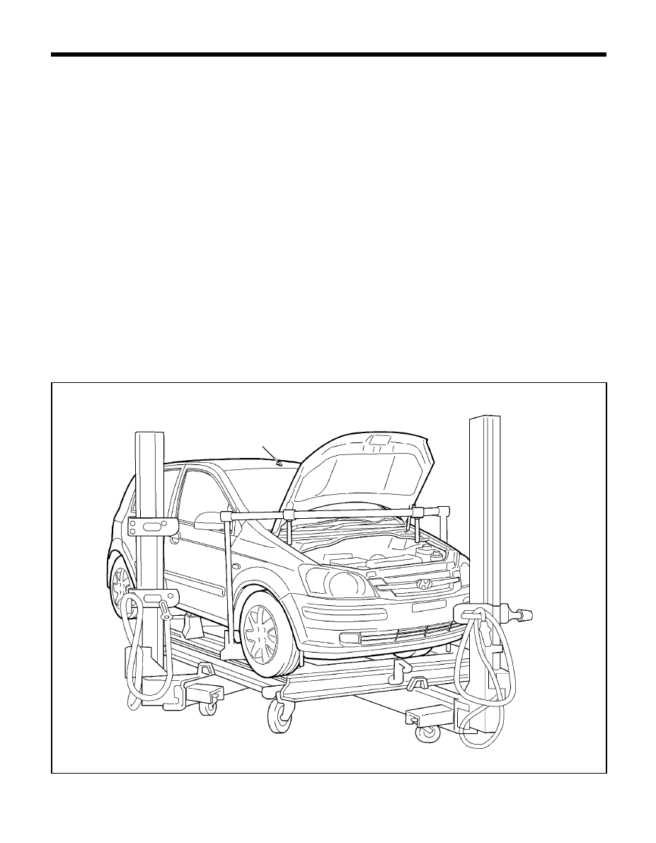
The repairs described in this manual were performed on Getz body shells. In some instances special fixtures were
welded in place to support the structure. During the repair of an actual vehicle, the interior would be fully disassembled
and standard jack screws or portable braces may be used for temporary support.
During the repair of an accident involved vehicle, the vehicle must first be returned to pre-impact dimensions prior
to beginning the sectioning repair procedures. The extent of damage that must be repaired should then be evaluated
to determine the appropriate repair procedures. This manual provides locations and procedures where structural
sectioning may be employed. It is the responsibility of the repair technician, based upon the extent of damage,
to determine which location and procedure is suitable for the particular damaged vehicle.
During the repair of a collision damaged automobile, it is impossible to fully duplicate the methods used in the
factory during the vehicle manufacture. Therefore, auto body repair techniques have been developed to provide
a repair that has strength properties equivalent to those of the original design and manufacture.
Certain guidelines and precaution are noted as follow.
TB-0010
7
GENERAL INFORMATION - SRS Air-bag
SRS AIR-BAG
SYSTEM COMPONENT
The Hyundai Getz is equipped with a Supplemental Restraint System AIR-BAG to provide the vehicle's driver and/
or the front passenger with additional protection than that offered by the seat-belt system alone, in case of a
frontal impact of sufficient severity.
When handling airbag components (removal, installation or inspection, etc.), always follow the directions given in
the repair manual for the relevant model to prevent the occurrence of accidents and airbag malfunction.
Also take the following precautions when repairing the body:
1. Work must be started after approximately 30 seconds or longer from the time the ignition switch is turned
to the LOCK position and the negative (-) terminal cable is disconnected from the battery. (The airbag system
is equipped with a back-up power source so that if work is started within 30 seconds of disconnecting the
negative (-) terminal cable of the battery, the airbag may be deployed.)
When the negative(-) terminal cable is disconnected from the battery, memory of the clock and audio systems
will be cancelled. So before starting work, make a record of the contents memorized by the audio memory
system. Then when work is finished, reset the audio system as before and adjust the clock.
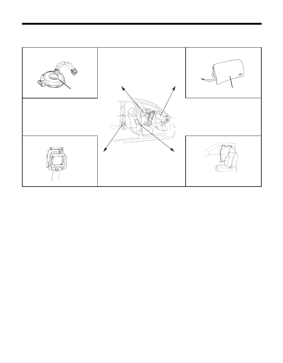
2. When using electric welding, first disconnect the air-bag connectors under the steering column near the MULTI-
FUNCTION SWITCH and the passenger's side crash pad before starting work.
3. Store the air-bag modules where the ambient temperature remains below 93
°
C (200
°
F), without high humidity
and away from electrical noise.
4. WARNING/CAUTION labels are attached to the periphery of the air-bag components.
Refer to the Getz SHOP MANUAL
ERKB012A
Clock spring
PAB
BPT
When it is deployed
8
GENERAL INFORMATION - Electronic parts
ELECTRONIC PARTS
Vehicles today include a great many electronic parts and components, and these are in general very susceptible to
adverse effects caused by overcurrent, reverse current, electromagnetic waves, high temperature, high humidity
impacts, etc.
In particular such electronic components can be damaged if there is a large current flow during welding from the body
side.
Therefore, take the following precautions during body repair to prevent damage to the CONTROL MODULS (ECM, TCM,
ABS CM, SRS CM, etc.)
1. Before removing and inspecting the electrical parts or before starting electric welding operations, disconnect the
negative (-) terminal cable from the battery.
2. Do not expose the CONTROL MODULS to ambient temperatures above 80°
C
(176°
F
).
NOTE :
If it is possible the ambient temperatures may reach 80°
C
C
C
C
C
(176°
F
F
F
F
F
) or more, remove the CONTROL MODULS
from the vehicle before starting work.
3. Be careful not to drop the CONTROL MODULS and not to apply physical shocks to them.
CORROSION PROTECTION AND SEALING
Proper corrosion protection and sealing is an important part of any repair. When reviewing these repair procedures, it
is important to recognize the need for corrosion restoration to provide for long term strength of the repaired member.
A two part epoxy primer was applied to the metal surfaces during the latter part of the repair. For closed sections,
such as front and rear rails, rocker panels and pillars, the primer is applied without applying the metal conditioner and
the conversion coating. These steps are omitted to insure that no rinse water is trapped in the closed sections. The
primer application in followed by an application of an oil or wax based rust proofing material.
After the corrosion restoration process for the closed sections are completed, then the process can be applied to all
exterior sections. For exterior surfaces, both metal conditioner and conversion coating treatments are applied to the
exterior surface prior to application of the epoxy primer. The procedure in applying the corrosion restoration process
is important order to insure that moisture, due to the water rinsing of the metal conditioner and conversion coating is
not inadvertently trapped inside any closed section before the epoxy primer and rust proofing materials have been
applied.
Appropriate seam sealers are then applied to all joints. Follow manufacturer's recommendations for the appropriate type
of seam sealer to be used at each seam or joint.
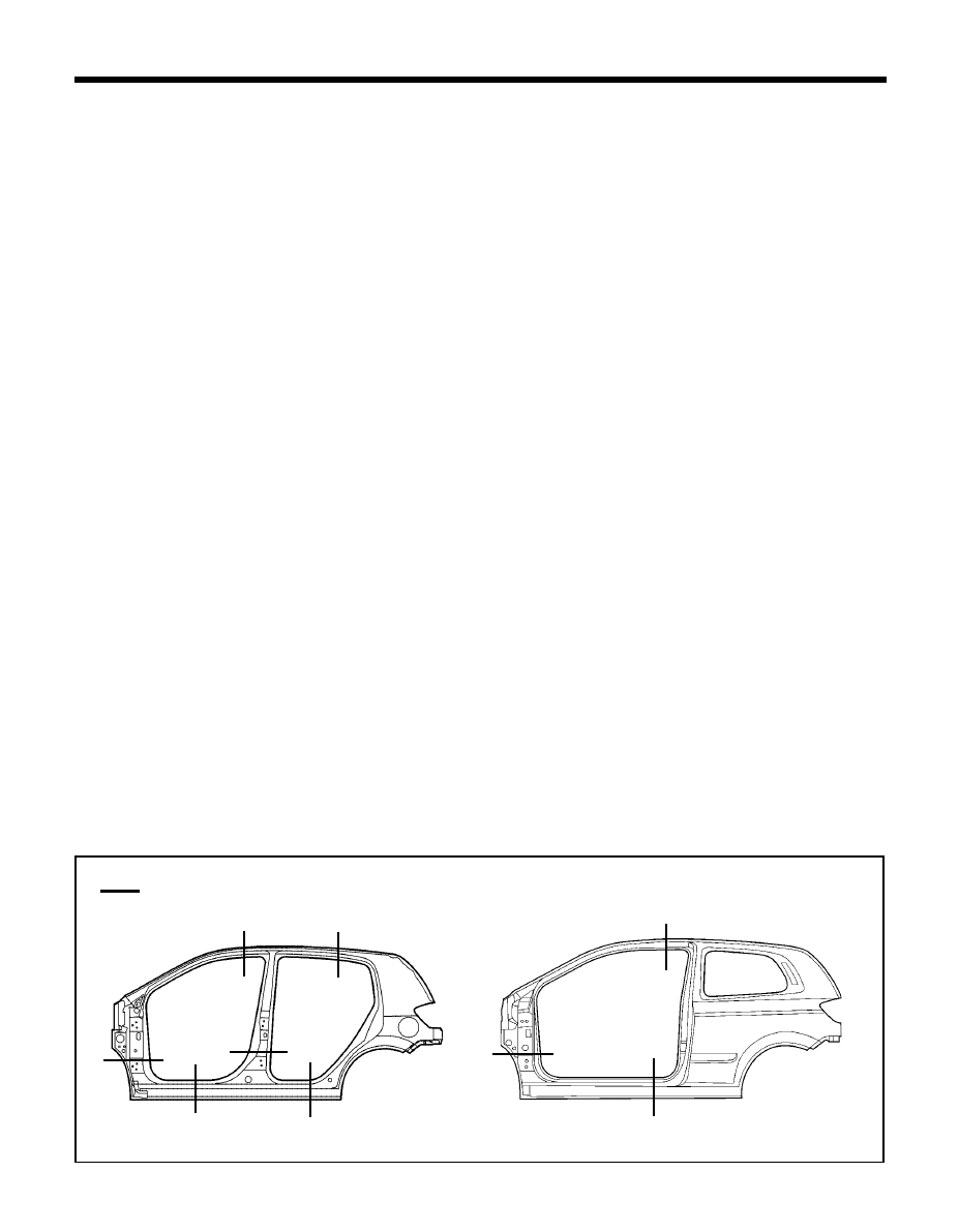
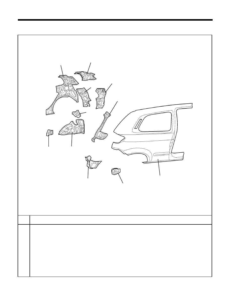
SIDE BODY PANELS
The side body panel for Getz is designed and stamped from a single piece of sheet metal in factory as shown in the
figure. While the entire side panel is available for service, the partial panels sectioned by several damaged areas are
also available. Therefore when repairing side body, refer to "Replacement parts section" of this manual to select and
use the appropriate part.
TB-0008/TB-0008A
: Service part line
3 DOOR
9
WELDING
All repairs in this manual require the use of a Metal-Inert Gas (MIG) welder, Gas (oxyacetylene) welding must
not be used.
Both high strength steel and mild steel can be welded using the MIG welder. The I-CAR recommendations for
welding should be followed. The shielding gas should be 75% Argon and 25% CO2.
The recommended welding wire size is 0.23" and the wire should satisfy the American Welding Society standard
code AWSER70S-6.
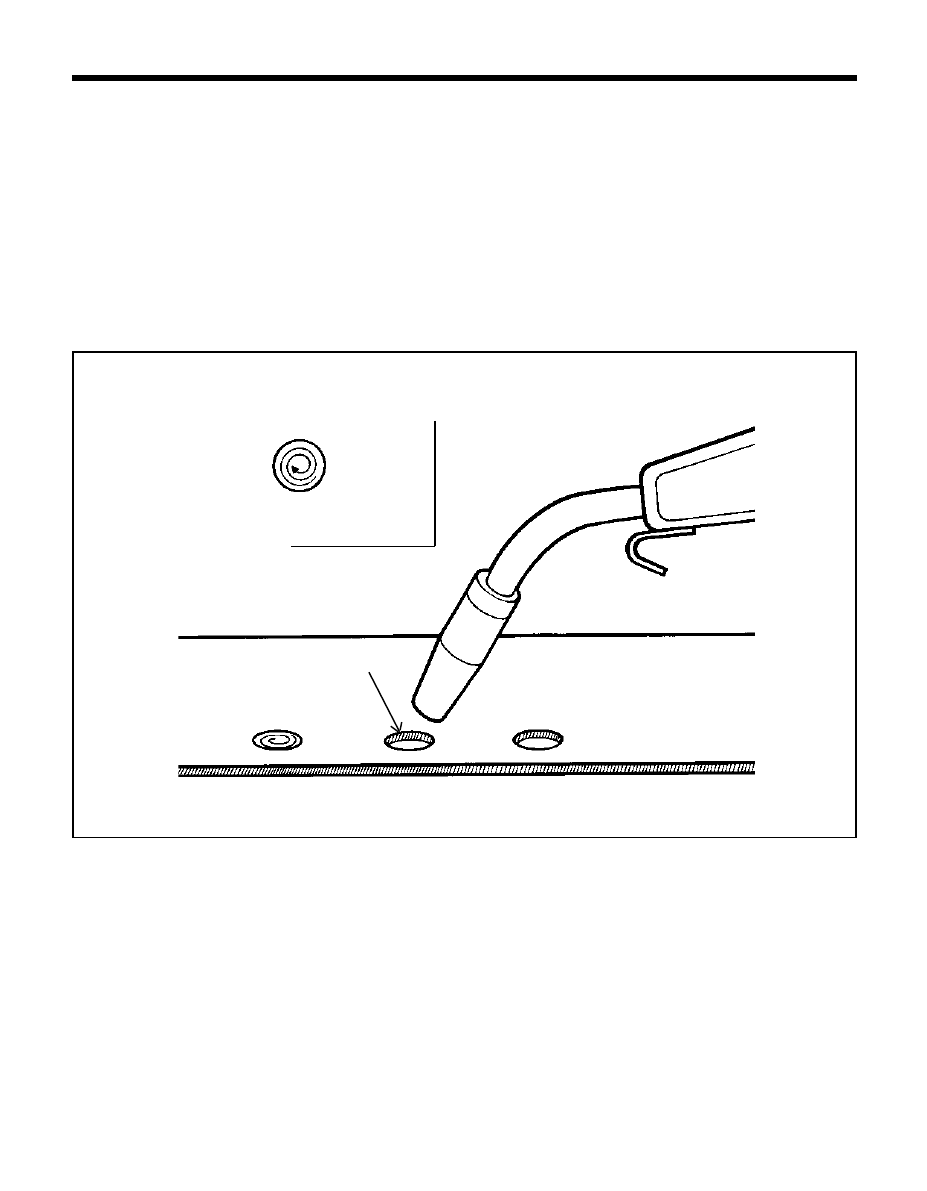
During the repair process, plug welds are used to duplicate original factory spot welds. All plug welds should be
done with the MIG welder. An 8 mm (5/16") hole is placed in the top (welding side) sheetmetal.
You then begin welding along the edges and the spiral towards the center (see illustration). This is important so
that weld penetration between the two metal pieces takes place along the circumference of the circle.
GENERAL INFORMATION - Welding
CON-0040
Weld around
edges first
working in to
wards the
center
(Top wiew)
8mm or 5/16" dia. hole
Illustration-Welding in collision Repair
PLUG WELDING

BODY
CONSTRUCTION
12
BODY CONSTRUCTION - Body components
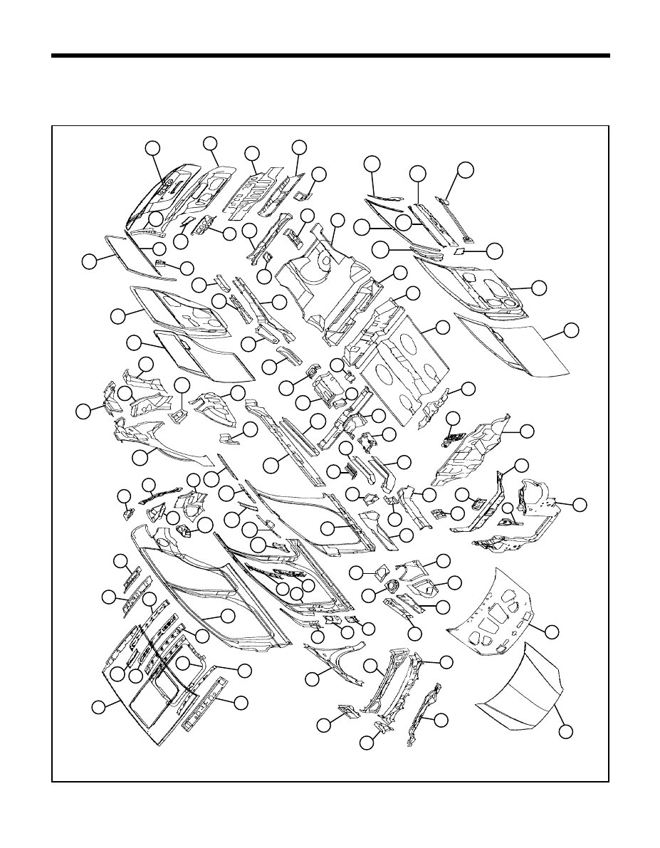
BODY COMPONENTS
Body construction will sometimes differ depending on specifications and country of destination. Therefore, please keep in
mind that the information contained herein is based on vehicles for general destination.
TB-0050
22
84
15
16
17
14
93
94
67
98
101
99
100
102
103
106
104
105
18
13
19
21
25
27
28
26
23
24
92
20
29
30
32
33
34
35
12
11
8
9
6
7
5
1
4
2
3
91
95
97
96
40
39
75
74
73
72
71
76
79
81
83
82
85
90
89
87
88
69
70
68
64
65
66
63
61
59
62
57
60
58
55
50
56
51
54
52
53
41
46
47
43
45
42
44
38
48
37
49
10
31
80
77
78
36
86

13
BODY CONSTRUCTION - Body components
1. Plastic carrier
2. Radiator support upper center panel
3. Radiator support center panel
4. Radiator support center reinforcement
5. Dash panel
6. Brake booster reinforcement
7. Dash lower center reinforcement
8. Center floor panel
9. Rear floor extension
10. Front seat mounting rear side bracket
11. Rear floor front cross member
12. Rear floor panel
13. Towing hook bracket
14. Rear seat rear bracket
15. Rear floor center cross member
16. Tail gate striker reinforcement
17. Rear transverse member
18. Back panel
19. Tail gate wiper motor reinforcement
20. Lifter tail gate side reinforcement
21. Tail gate inner panel
22. Tail gate outer panel
23. Rear door reinforcement beam
24. Rear door belt outer rail
25. Rear door frame rear reinforcement
26. Rear door window channel
27. Rear door inner panel
28. Rear door outer panel
29. Rear floor side member extension
30. Rear floor side member reinforcement
31. Rear floor side member
32. Trailing arm mounting reinforcement
33. Rear floor side front member
34. Parking brake cable mounting bracket
35. Parking brake aperture panel
36. Front seat mounting rear inner bracket
37. Front seat cross member
38. Center floor front reinforcement
39. Center floor side member
40. Side sill inner panel
41. Side inner panel
42. Front side rear member
43. Front side rear lower reinforcement
44. Front side rear lower member
45. Front side member rear lower extension
46. Front side outer member
47. Transmission mounting bracket
48. Front side inner member
49. Battery tray leg reinforcement
50. Fender apron inner front panel
51. Fender apron inner panel
52. Cowl under cover extension
53. Front shock absorber cover panel
54. Fender apron upper member
55. Apron upper reinforcement
56. Hood inner panel
57. Hood outer panel
58. Cowl inner lower panel
59. Cowl side outer panel
60. Cowl top outer panel
61. Cowl side upper outer member
62. Cowl inner rear panel
63. Fender panel
64. Front door upper mounting reinforcement
65. Front pillar outer bracket
66. Front door lower mounting bracket
67. Side outer panel
68. Side outer reinforcement
69. Center pillar outer upper reinforcement
70. Center pillar outer lower reinforcement
71. Rear door lower mounting bracket
72. Front pillar inner upper reinforcement
73. Front side belt upper mounting bracket
74. Assist hold mounting bracket
75. Roof side inner rail
76. Fuel filler housing
77. Quarter outer rear lower extension
78. Quarter outer rear upper extension
79. Rear combination lamp housing panel
80. Tail gate lifter bracket
81. Roof rear upper rail
82. Roof rear lower rail
83. Roof rear center rail
84. Roof center side rail
85. Roof center rail
86. Side roof rear lower reinforcement
87. Side roof reinforcement ring
88. Roof center front rail
89. Roof front rail
90. Roof panel
91. Quarter inner panel
92. Quarter inner upper reinforcement
93. Quarter inner rear lower extension
94. Quarter pillar inner reinforcement
95. Rear spring house cover
96. Wheel house inner front extension
97. Wheel house inner panel
98. Front door outer panel
99. Front door inner panel
100. Front door quadrant reinforcement
101. Front door hinge lower bracket
102. Front door window upper channel
103. Front door frame rear reinforcement
104. Front door belt outer rail
105. Front door belt inner rail
106. Front door reinforcement beam
14
BODY CONSTRUCTION - Zinc-galvanized steel panels
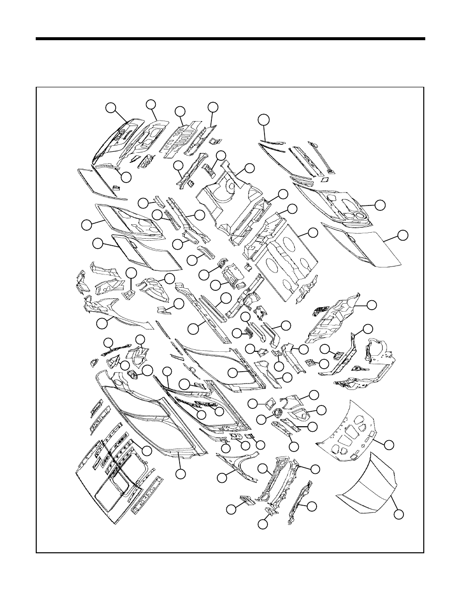
ZINC-GALVANIZED STEEL PANELS
Because galvanized steel panel has excellent resistance, it is used in areas which have a high possibility of painting
deficiency below.
TB-0050
13
10
52
66
67
11
12
14
15
16
17
18
20
21
22
23
4
5
7
3
2
1
62
63
65
64
25
24
56
57
60
54
55
53
49
50
51
48
46
44
47
42
45
43
40
35
41
36
39
37
38
26
31
32
28
30
27
29
33
34
19
58
59
68
61
8
9
6

15
BODY CONSTRUCTION - Zinc-galvanized steel panels
1. Radiator support upper center panel
2. Radiator support center reinforcement
3. Dash panel
4. Center floor panel
5. Rear floor extension
6. Rear floor front cross member
7. Rear floor panel
8. Towing hook bracket
9. Rear floor center cross member
10. Rear transverse member
11. Back panel
12. Tail gate inner panel
13. Tail gate outer panel
14. Rear door frame rear reinforcement
15. Rear door inner panel
16. Rear door outer panel
17. Rear floor side member extension
18. Rear floor side member reinforcement
19. Rear floor side member
20. Trailing arm mounting reinforcement
21. Rear floor side front member
22. Parking brake cable mounting bracket
23. Parking brake aperture panel
24. Center floor side member
25. Side sill inner panel
26. Side inner panel
27. Front side rear member
28. Front side rear lower reinforcement
29. Front side rear lower member
30. Front side member rear lower extension
31. Front side outer member
32. Transmission mounting bracket
33. Front side inner member
34. Battery tray leg reinforcement
35. Fender apron inner front panel
36. Fender apron inner panel
37. Cowl under cover extension
38. Front shock absorber cover panel
39. Fender apron upper member
40. Apron upper reinforcement
41. Hood inner panel
42. Hood outer panel
43. Cowl inner lower panel
44. Cowl side outer panel
45. Cowl top outer panel
46. Cowl side upper outer member
47. Cowl inner rear panel
48. Fender panel
49. Front door upper mounting reinforcement
50. Front pillar outer bracket
51. Front door lower mounting bracket
52. Side outer panel
53. Side outer reinforcement
54. Center pillar outer upper reinforcement
55. Center pillar outer lower reinforcement
56. Rear door lower mounting bracket
57. Fuel filler housing
58. Quarter outer rear lower extension
59. Quarter outer rear upper extension
60. Rear combination lamp housing panel
61. Side roof rear lower reinforcement
62. Quarter inner panel
63. Rear spring house cover
64. Wheel house inner front extension
65. Wheel house inner panel
66. Front door outer panel
67. Front door inner panel
68. Front door frame rear reinforcement
16
BODY CONSTRUCTION - High-strength steel panels
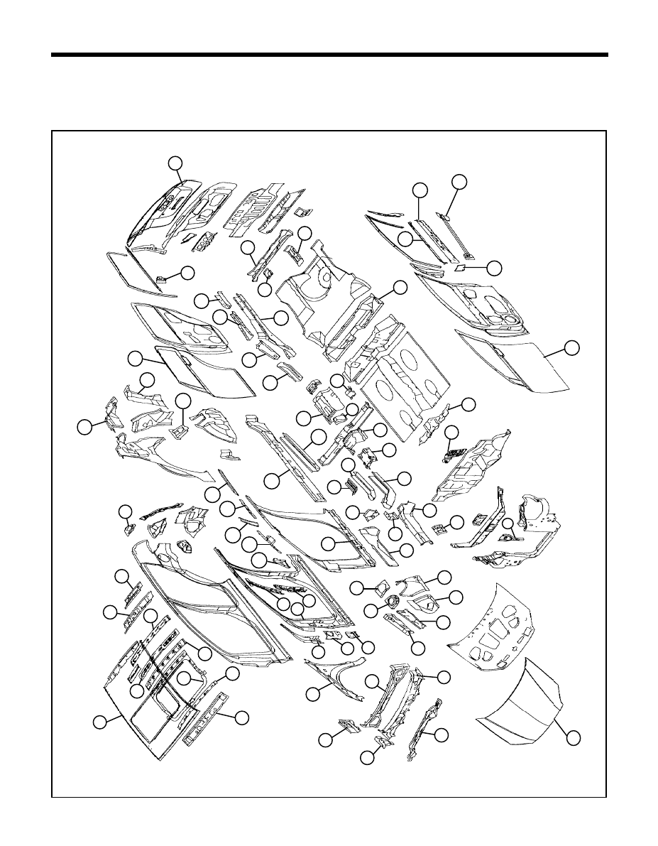
HIGH STRENGTH STEEL PANELS
Because High strength steel panel has excellent resistance, it is used in areas which have a high possibility of painting
deficiency below.
TB-0050
67
69
11
10
66
12
13
15
16
17
5
2
3
1
68
22
21
55
54
53
52
51
57
59
58
60
65
64
62
63
49
50
48
45
46
47
44
42
40
43
38
41
39
37
32
33
36
34
35
23
28
29
25
27
24
26
20
30
19
31
14
56
18
61
6
4
72
73
71
70
9
8
7

17
BODY CONSTRUCTION - High-strength steel panels
1. Radiator support center panel
2. Brake booster reinforcement
3. Dash lower center reinforcement
4. Front seat mounting rear side bracket
5. Rear floor front cross member
6. Towing hook bracket
7. Rear seat rear bracket
8. Rear floor center cross member
9. Tail gate outer panel
10. Rear door reinforcement beam
11. Rear door outer panel
12. Rear floor side member extension
13. Rear floor side member reinforcement
14. Rear floor side member
15. Trailing arm mounting reinforcement
16. Rear floor side front member
17. Parking brake aperture panel
18. Front seat mounting rear inner bracket
19. Front seat cross member
20. Center floor front reinforcement
21. Center floor side member
22. Side sill inner panel
23. Side inner panel
24. Front side rear member
25. Front side rear lower reinforcement
26. Front side rear lower member
27. Front side member rear lower extension
28. Front side outer member
29. Transmission mounting bracket
30. Front side inner member
31. Battery tray leg reinforcement
32. Fender apron inner front panel
33. Fender apron inner panel
34. Cowl under cover extension
35. Front shock absorber cover panel
36. Fender apron upper member
37. Apron upper reinforcement
38. Hood outer panel
39. Cowl inner lower panel
40. Cowl side outer panel
41. Cowl top outer panel
42. Cowl side upper outer member
43. Cowl inner rear panel
44. Fender panel
45. Front door upper mounting reinforcement
46. Front pillar outer bracket
47. Front door lower mounting bracket
48. Side outer reinforcement
49. Center pillar outer upper reinforcement
50. Center pillar outer lower reinforcement
51. Rear door lower mounting bracket
52. Front pillar inner upper reinforcement
53. Front side belt upper mounting bracket
54. Assist hold mounting bracket
55. Roof side inner rail
56. Tail gate lifter bracket
57. Roof rear upper rail
58. Roof rear lower rail
59. Roof rear center rail
60. Roof center rail
61. Side roof rear lower reinforcement
62. Side roof reinforcement ring
63. Roof center front rail
64. Roof front rail
65. Roof panel
66. Quarter inner upper reinforcement
67. Quarter pillar inner reinforcement
68. Rear spring house cover
69. Front door outer panel
70. Front door hinge lower bracket
71. Front door belt outer rail
72. Front door belt inner rail
73. Front door reinforcement beam
18
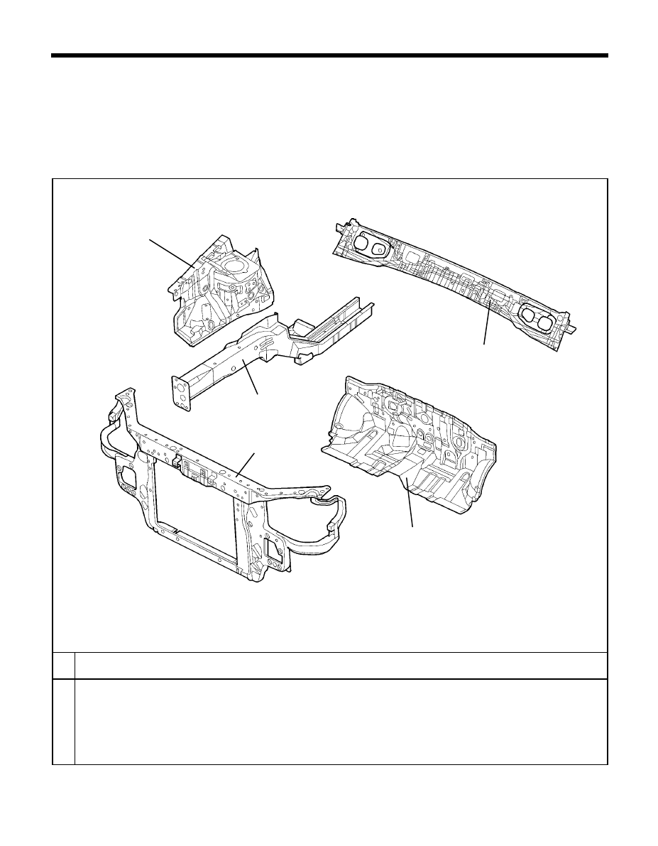
BODY CONSTRUCTION - Front body
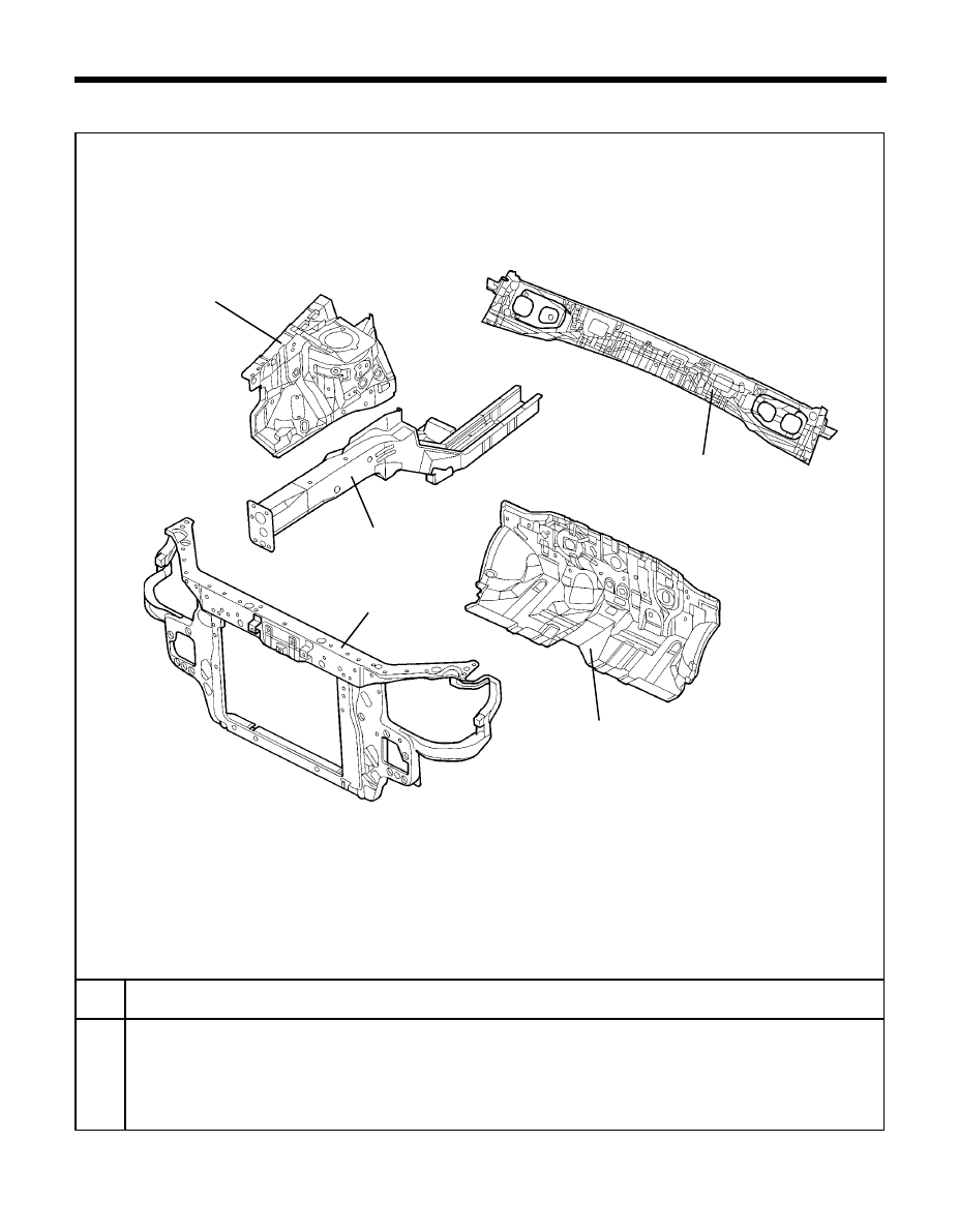
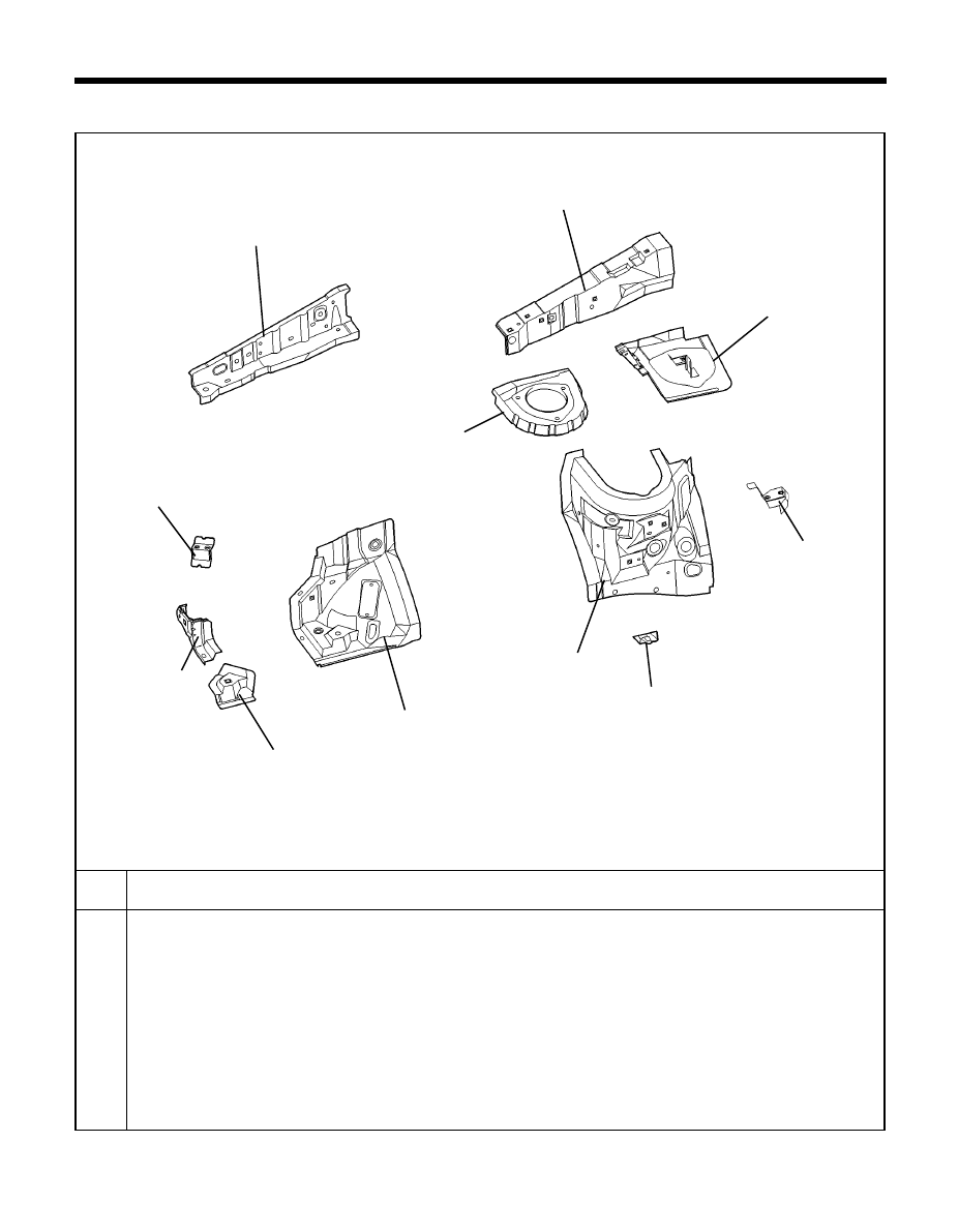
FRONT BODY
TB-60
PART NAME
No.
Radiator support complete member assembly
Fender apron panel assembly
LH/RH
Front side member assembly
LH/RH
Dash panel assembly
Cowl panel assembly
1
2
3
4
5
2
3
4
1
5
19
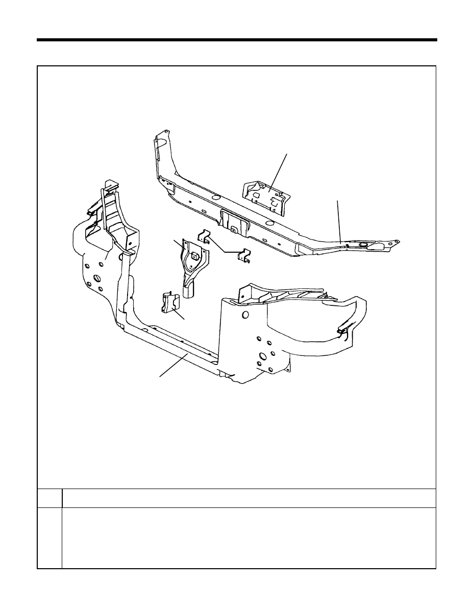
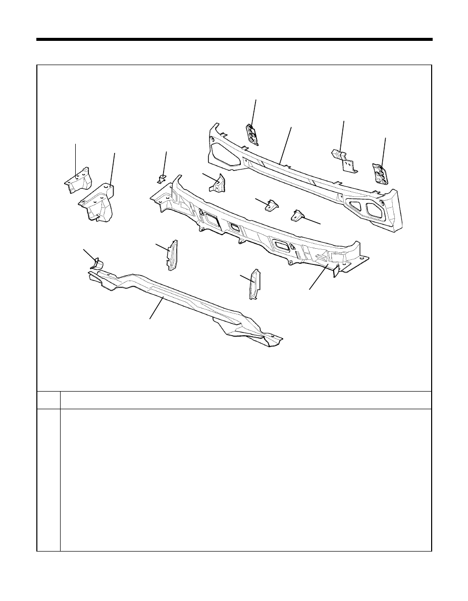
BODY CONSTRUCTION - Front body <Radiator support panel>
1. RADIATOR SUPPORT PANEL
PART NAME
No.
Radiator support center extension
Radiator support center panel
Horn mounting bracket
Radiator support upper center panel
Radiator support center reinforcement
1
2
3
4
5
6
Plastic carrier
TB-70
1
2
3
4
5
6
20
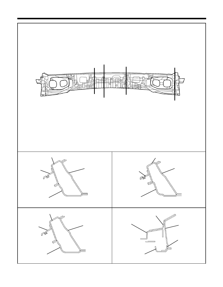
SECTION B-B'
SECTION A-A'
SECTION D-D'
SECTION C-C'
BODY CONSTRUCTION-Front body <Radiator support panel>
TB-80
80-3
80-2
80-1
80-4
A'
A
B
B'
C'
D
D'
C
Í
Front end module
Hood panel
Front end module
Fender apron complete panel
Front bumper rail
Front end module
Fender panel
<Cross-Sectional Views>
Head lamp
Front side complete
member
Hood panel
Front end module
Í
Í
Í
Í
Í
Í
Í
21
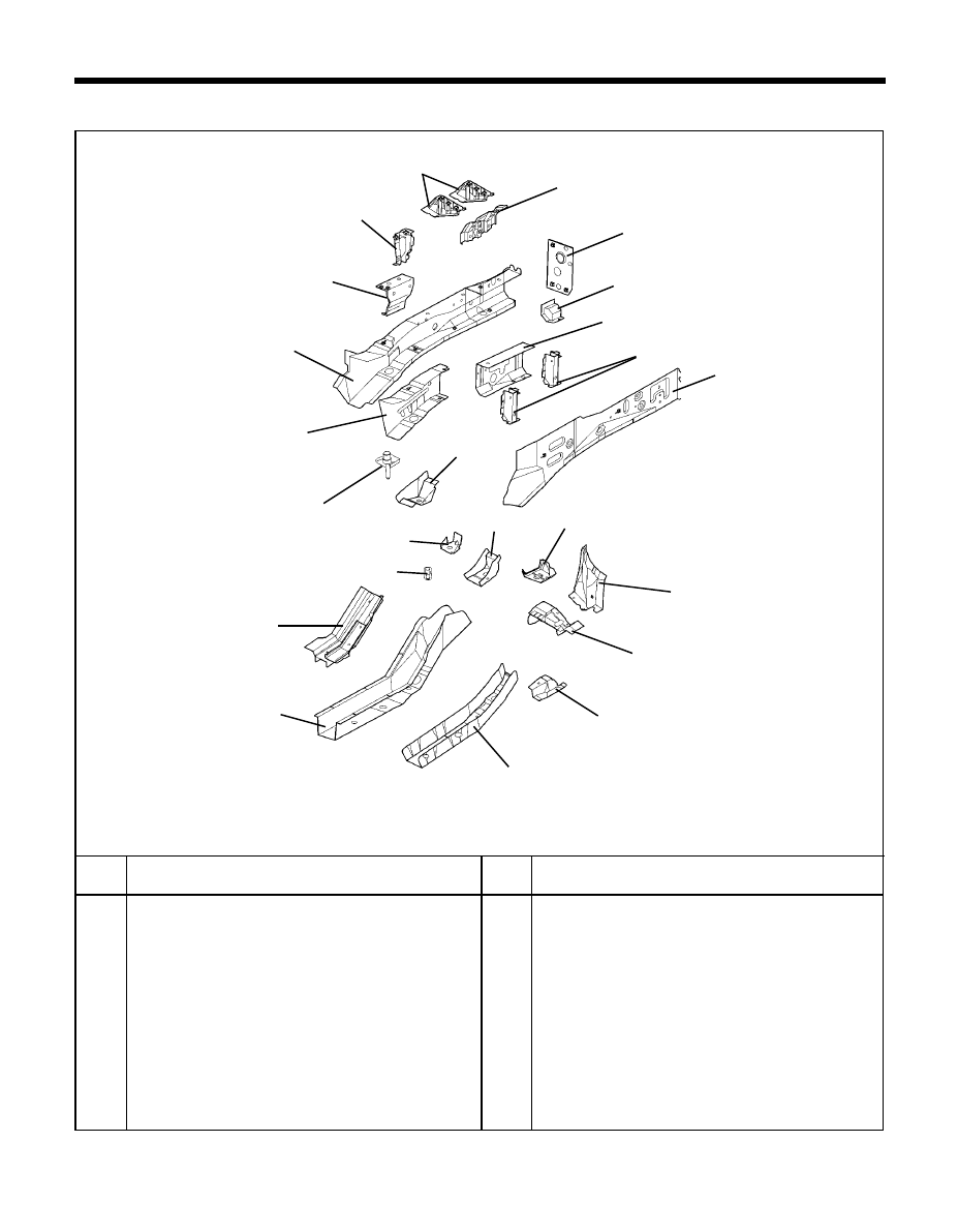
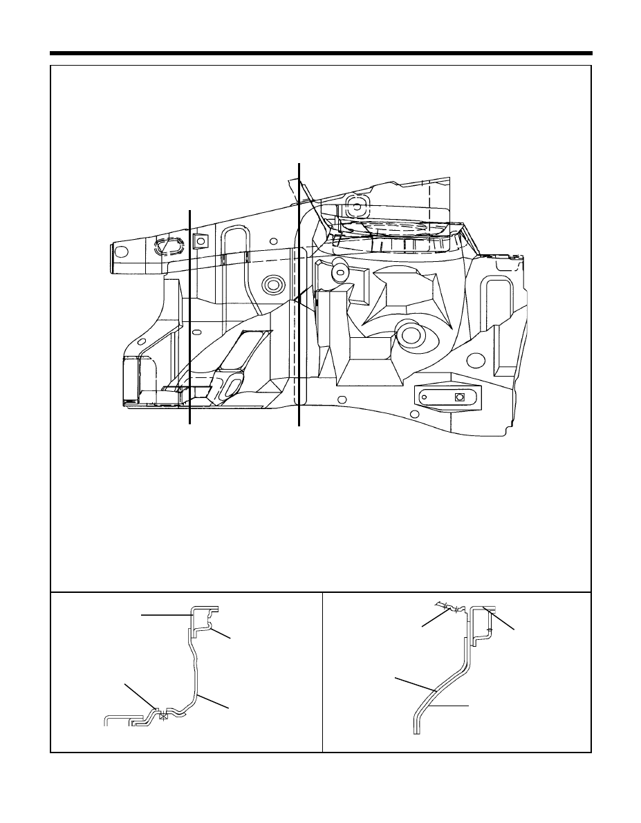
BODY CONSTRUCTION - Front body <Front side member>
2. FRONT SIDE MEMBER
PART NAME
Front side inner member
Front side outer member
Carrier mounting bracket
Battery try leg reinforcement
Battery try leg bracket
Center member mounting front reinforcement
Transmission mounting bracket
Transmission mounting front support
Engine mounting front support
Engine mounting front bracket
Front towing hook mounting bracket
Front side inner reinforcement
No.
1
2
3
4
5
6
7
8
9
10
11
12
TB-130
15
5
6
13
21
20
19
2
9
8
7
1
12
23
14
16
18
17
10
22
11
3
4
PART NAME
Cross member mounting front bracket
Front side rear lower member
Front side rear upper member
Front side rear lower reinforcement
Front tie down bracket
Front side rear lower bracket
Front side rear lower extension
Front side rear lower support
Cross member mounting rear reinforcement
Cross member mounting rear bracket
Pipe nut (M14)
No.
13
14
15
16
17
18
19
20
21
22
23
22
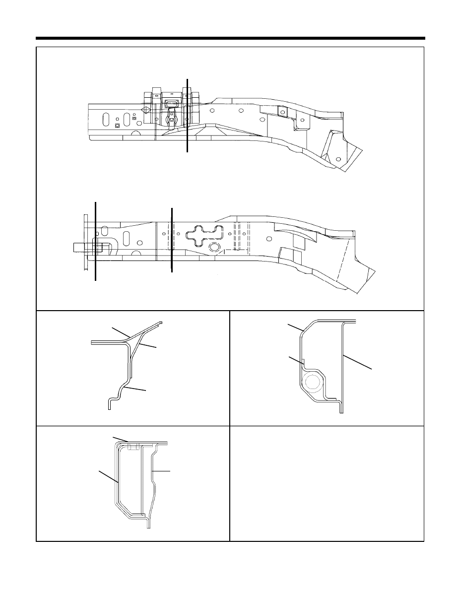
SECTION C-C'
SECTION B-B'
BODY CONSTRUCTION - Front body <Front side member, LH/RH>
<Cross-Sectional Views>
LH
140-1
TB-140
140-2
TB-140A
RH
A
A'
B'
B
C
C'
Í
Í
Í
Í
Í
Í
Front side outer member
Front side inner member
Front towing hook
mounting bracket
Front side outer
member
Front side inner member
Engine mounting support
SECTION A-A'
140-3
Battery tray leg bracket
Front side inner member
Battery tray leg
reinforcement
23
BODY CONSTRUCTION - Front body <Fender apron panel>
3. FENDER APRON PANEL
No.
1
2
3
4
5
6
7
8
9
10
11
PART NAME
Fender apron inner front panel
Fender apron inner panel
LH/RH
Front shock absorber cover panel
LH/RH
Cowl under cover extension assembly LH/RH
Engine side mounting reinforcement
Fender mounting bracket
LH/RH
Washer reservoir mounting bracket
Fender apron upper reinforcement
LH/RH
Fender apron upper member
LH/RH
Fender apron rear bracket
LH/RH
Brake hose mounting bracket
TB-180
8
9
4
5
1
10
3
2
11
6
7
24
SECTION A-A'
SECTION B-B'
BODY CONSTRUCTION - Front body <Fender apron panel>
<Cross-Sectional Views>
190-1
190-2
TB-190
A'
A
B Í
B' Í
Í
Í
Fender apron upper
reinforcement
Fender apron upper
member
Fender apron inner
complete panel
Cowl under cover extension
Fender apron front
complete panel
Engine side mounting
reinforcement
Fender apron front
complete panel
Fender apron inner complete
panel
25
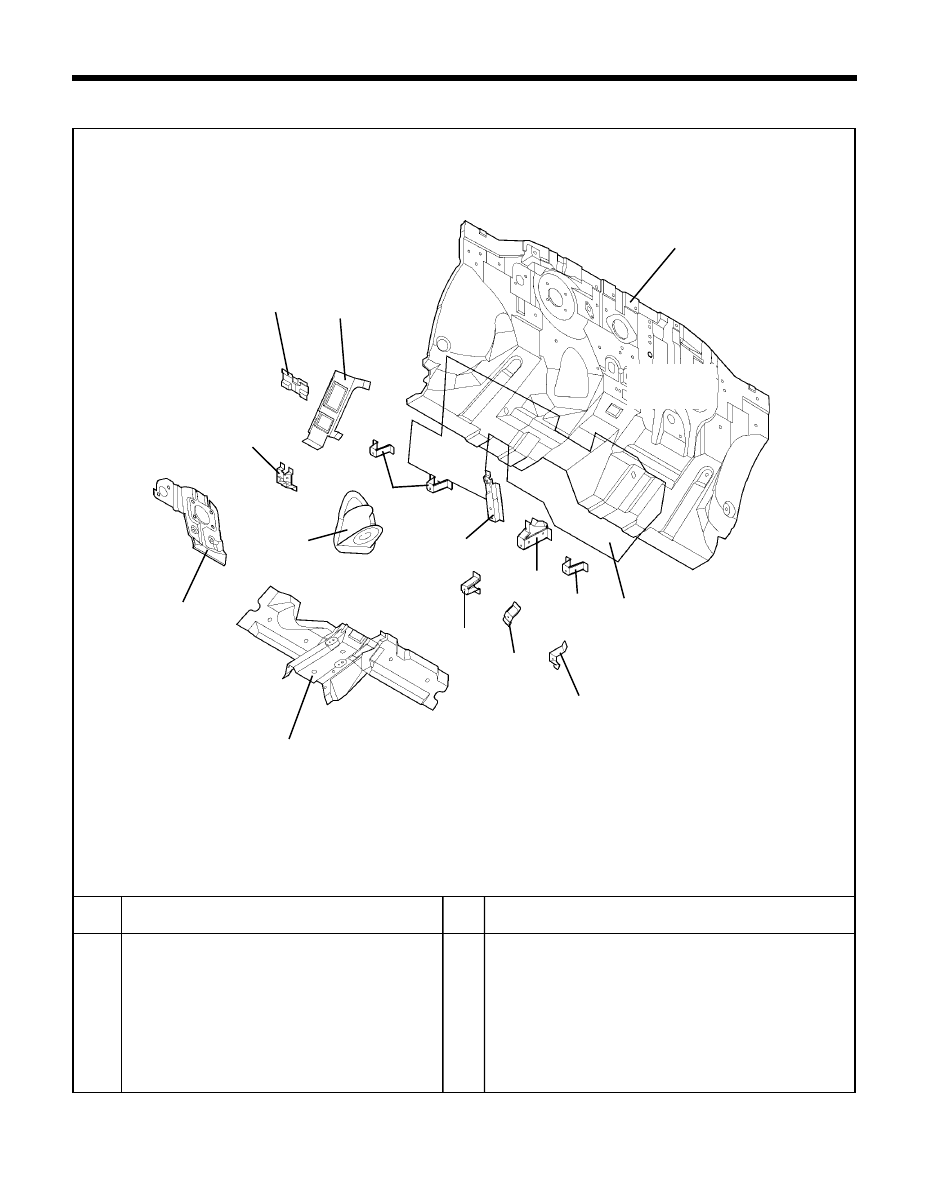
BODY CONSTRUCTION - Front body <Dash panel>
4. DASH PANEL
No.
1
2
3
4
5
6
7
8
PART NAME
Dash panel
Foot rest bracket
Heater upper mounting bracket
Heater lower mounting bracket
Blower mounting bracket
Accelerator pedal mounting bracket
Dash lower center reinforcement
Dust cover panel
TB-220
No.
9
10
11
12
13
14
15
PART NAME
Evaporator upper mounting bracket
LH
Evaporator upper mounting bracket
RH
Evaporator lower mounting bracket
Electronic control unit mounting bracket
Dash panel antivibration pad
Fuel filler mounting bracket
Brake booster reinforcement
15
7
8
5
13
11
4
3
6
12
1
2
14
9
10
26
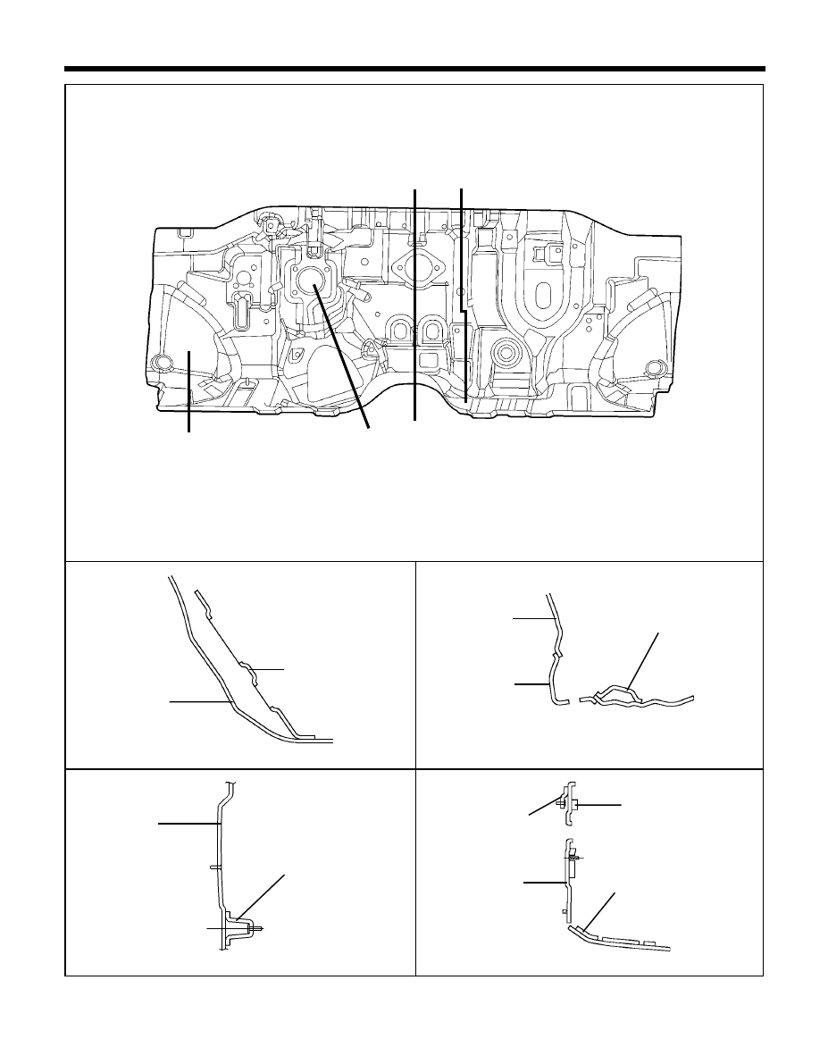
BODY CONSTRUCTION - Front body <Dash panel>
SECTION B-B'
SECTION A-A'
SECTION C-C'
SECTION D-D'
<Cross-Sectional Views>
TB-230
230-1
230-2
230-4
230-3
Foot rest bracket
Dash panel
Dash lower center
reinforcement
Dust cover panel
Dash panel
Heater lower mounting
bracket
Dash lower center panel
reinforcement
Dash panel anti pad
Dash panel
Dash panel
Fuel filter mounting
bracket
C'
C
A
A'
B
B'
D'
D
Í
Í
Í
Í
Í
Í
Í
Í
27
BODY CONSTRUCTION - Front body <Cowl panel>
5. COWL PANEL
1
2
3
4
5
6
7
8
9
10
11
12
13
14
15
TB-280
No.
PART NAME
Cowl top outer panel
Cowl inner rear panel
Cowl inner lower panel
Cowl inner rear plate
Brake bar mounting bracket
Cowl inner rear plate
Wiper pivot mounting side bracket
LH/RH
Wiper center mounting bracket
Cowl under cover mounting bracket
Cowl inner lower support
RH
Cowl inner lower support
LH
Cowl side outer reinforcement
LH/RH
Fender mounting bracket
LH/RH
Cowl side outer panel
LH/RH
Cowl inner lower side bracket
LH/RH
12
14
15
3
1
13
7
4
2
5
6
8
9
11
10
28
BODY CONSTRUCTION - Front body <Cowl panel>
SECTION A-A'
SECTION D-D'
SECTION B-B'
290-2
290-4
TB-290
290-1
<Cross-Sectional Views>
Cowl top outer panel
Cowl inner rear
complete panel
Wiper center
mounting bracket
Cowl top outer panel
Cowl top outer panel
Cowl inner rear
complete panel
Cowl inner lower
side bracket
Cowl under
cover mounting
bracket
Cowl inner lower panel
Cowl side outer panel
Cowl inner lower
panel
Cowl inner rear
complete panel
Cowl inner rear panel
SECTION C-C'
290-1
Cowl top outer panel
Cowl inner rear
complete panel
Wiper center
mounting bracket
Cowl inner lower
panel
B'
B
Í
Í
A'
A
Í
Í
C'
C
Í
Í
D'
D
Í
Í
29
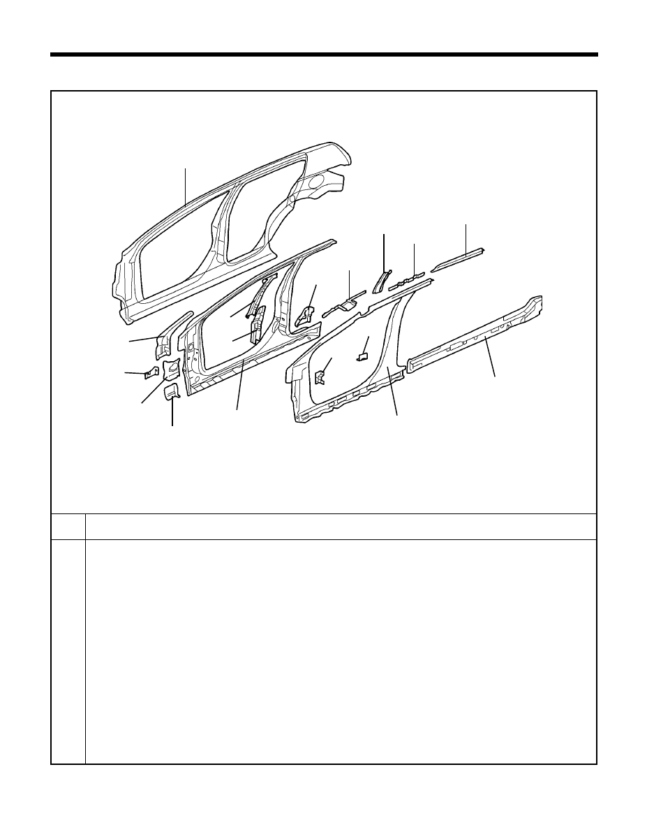
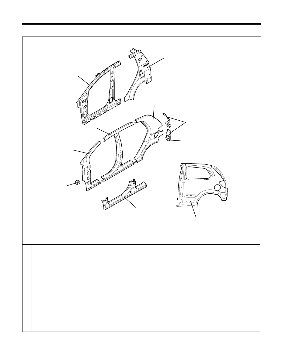
BODY CONSTRUCTION - Side body
1
2
3
4
5
6
7
8
9
10
11
12
13
14
15
16
17
No.
TB-340
PART NAME
Side outer panel
Front door upper mounting reinforcement
Front door checker mounting bracket
Front pillar outer bracket
Front door lower mounting bracket
Side outer reinforcement
Center pillar outer upper reinforcement
Center pillar outer lower reinforcement
Rear door lower mounting bracket
Front pillar inner upper reinforcement
Front seat belt upper mounting bracket
Assist handle mounting bracket
Roof side inner rail
Side inner panel
Cowl center bar mounting bracket
Front seat belt lower mounting bracket
Side sill inner panel
SIDE BODY
1
3
2
11
12
10
13
6
7
4
5
8
9
15
16
14
17
30
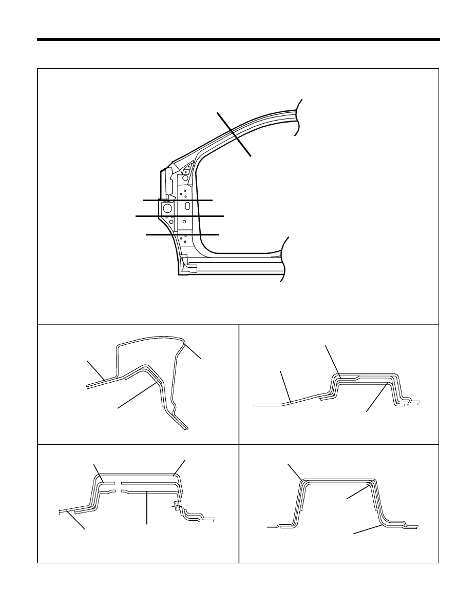
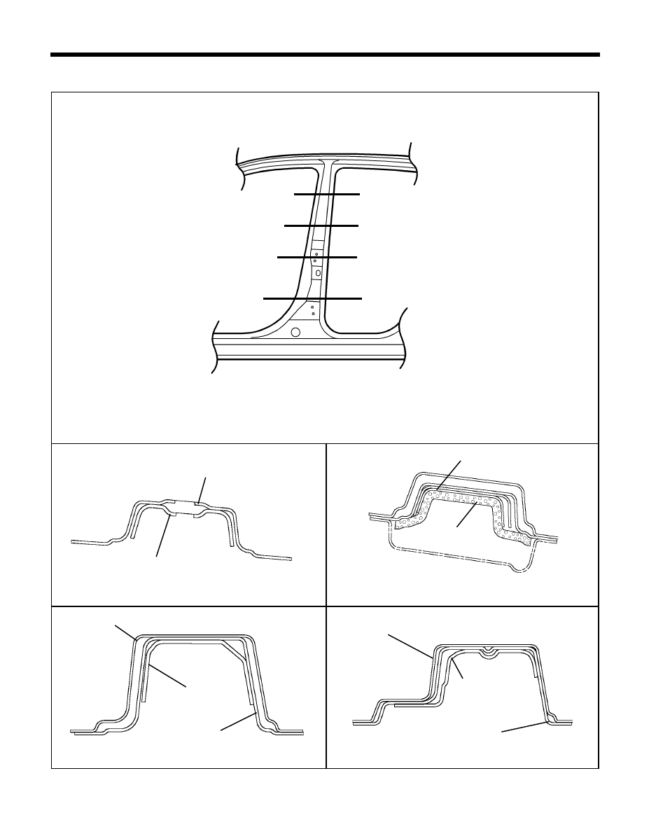
BODY CONSTRUCTION - Side body <Front pillar>
SECTION B-B'
SECTION A-A'
SECTION C-C'
SECTION D-D'
1. FRONT PILLAR
<Cross-Sectional Views>
TB-350
350-1
350-2
350-3
350-4
Side outer panel
Side outer reinforcement
Front door checker mounting
bracket
Side outer reinforcement
Side outer panel
Front door lower
mounting bracket
Front door upper mounting reinforce-
ment
Side outer panel
Side outer panel
Side outer reinforcement
Front door upper
mounting reinforcement
Front door upper
mounting reinforcement
Side outer panel
A
A'
Ó
Ó
C
C'
Ó
Ó
B'
B
Ð
Ð
D
D'
Ð
Ð
31
SECTION C-C'
SECTION B-B'
SECTION A-A'
BODY CONSTRUCTION - Side body <Center pillar>
2. CENTER PILLAR
TB-400
400-1
400-2
SECTION D-D'
<Cross-Sectional Views>
Side outer reinforcement
Center pillar outer upper reinforcement
Side outer reinforcement
Center pillar outer
lower reinforcement
Side outer reinforcement
400-4
Side outer reinforcement
Side outer panel
Side outer panel
Rear door lower
mounting bracket
400-3
Center pillar upper
deadening pad
A
A'
Ð
Ð
B
B'
Ð
Ð
C
C'
Ð
Ð
D
D'
Ð
Ð
32
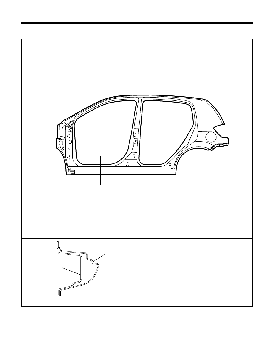
BODY CONSTRUCTION - Side body <Side sill>
3. SIDE SILL
<Cross-Sectional Views>
SECTION B-B'
SECTION A-A'
TB-0008
450-1
Side outer panel
Side outer reinforcement
A
A'
Í
Í
33
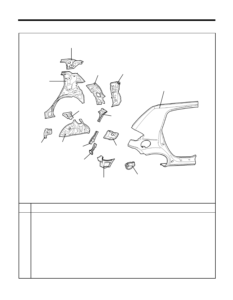
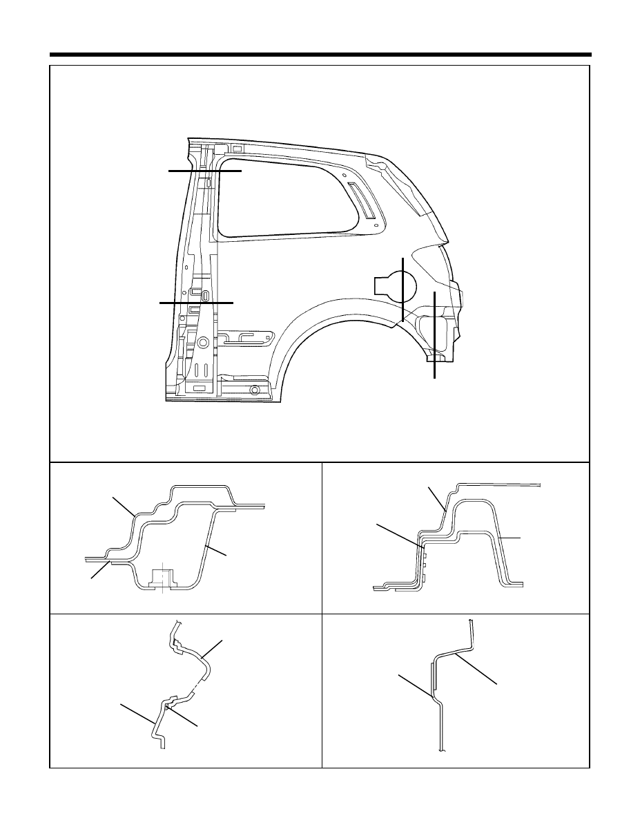
BODY CONSTRUCTION - Side body <Quarter panel>
4. QUARTER PANEL
No
5
4
3
11
1
2
13
14
1
Wheel house inner front extension
LH/RH
2
Quarter inner upper reinforcement assembly
LH/RH
3
Quarter inner panel
LH/RH
4
Quarter inner rear lower extension
LH/RH
5
Quarter pillar inner reinforcement assembly
LH/RH
6
Rear spring house cover
LH/RH
7
Quarter outer rear upper extension
LH/RH
8
Quarter outer rear center upper extension LH/RH
9
Quarter outer rear center extension
LH/RH
10
Rear combination lamp housing panel
LH/RH
11
Quater outer rear lower extension
LH/RH
12
Fuel filler housing
13
Side outer panel
LH/RH
14
Wheel house inner panel
LH/RH
PART NAME
TB-480A
7
12
9
10
8
6
34
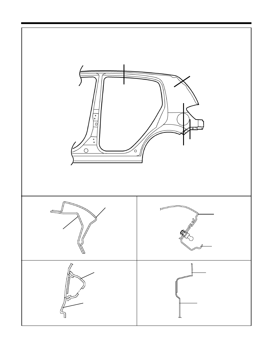
SECTION C-C'
BODY CONSTRUCTION - Side body <Quarter panel>
<Cross-Sectional Views>
SECTION A-A'
SECTION B-B'
490-1
490-2
TB-08
SECTION D-D'
Side outer panel
Side outer reinforcement
Side outer panel
Rear pillar panel
Fuel filler housing
Quarter outer rear lower
extension
490-4
Side outer panel
Side outer panel
490-3
Ó
A'
Ó
A
Ó
B'
B
C'
C
D'
D
Ó
Ó
Ó
Ó
Ó
35
BODY CONSTRUCTION - Side body <Quarter panel-3Door>
4-1. QUARTER PANEL (3DOOR)
No
5
4
3
9
1
2
11
8
6
1
Wheel house inner front extension
LH/RH
2
Quarter inner upper reinforcement assembly
LH/RH
3
Quarter inner panel
LH/RH
4
Quarter inner rear lower extension
LH/RH
5
Quarter pillar inner reinforcement
LH/RH
6
Rear spring house cover
LH/RH
7
Wheel house inner panel
LH/RH
8
Rear pillar panel assembly
LH/RH
9
Quarter outer rear lower extension
LH/RH
10
Fuel filler housing assembly
11
Side outer panel
LH/RH
PART NAME
TB-0480B
7
10
36
SECTION A-A'
SECTION C-C'
BODY CONSTRUCTION - Side body <Quarter panel - 3 Door>
<Cross-Sectional Views>
SECTION B-B'
809-3A
809-4
TB-809
SECTION D-D'
Side outer panel
Center pillar outer lower
reinfocement
Fuel filler housing
Quarter outer rear
lower extension
809-1
Mastic sealer
Side outer
reinforcement
C'
C
Í
Í
D'
D
Í
Í
Ð
A'
A
Ð
Ð
B
B
Ð
809-3
Side outer
reinforcement
Side outer panel
Side outer panel
Side outer
reinforcement
Front seat belt upper
reinforcement assembly
37
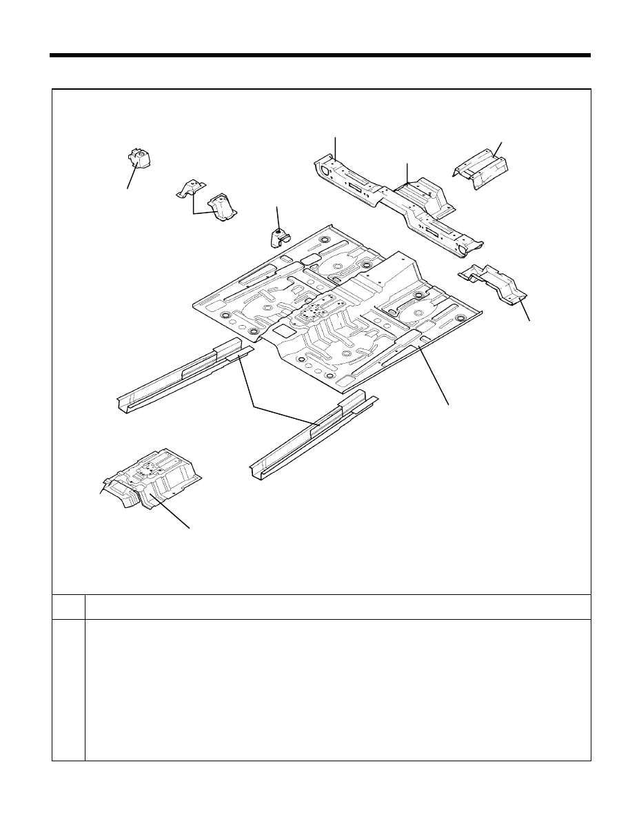
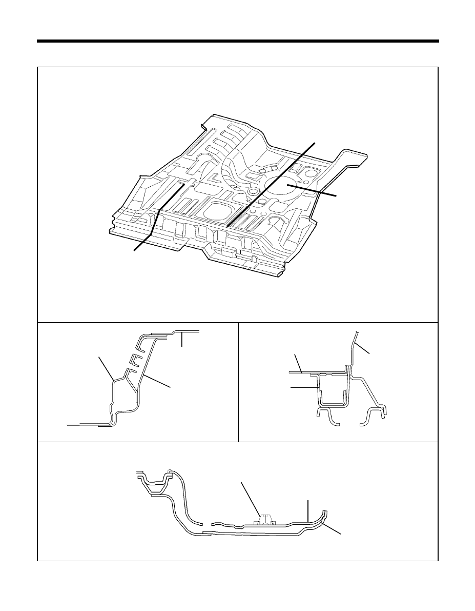
BODY CONSTRUCTION - Center floor
CENTER FLOOR PANEL
No
5
4
3
9
1
2
8
6
1
Center floor panel
2
Center floor front reinforcement
3
Parking brake aperture panel
4
Front seat cross member
5
TGS lever mounting bracket
6
Front seat mounting rear inner bracket
LH/RH
7
Front seat mounting rear side bracket
LH
8
Front seat mounting rear side bracket
RH
9
Center floor side member
LH/RH
10
Center floor tunnel brace
PART NAME
TB-539
7
10
38
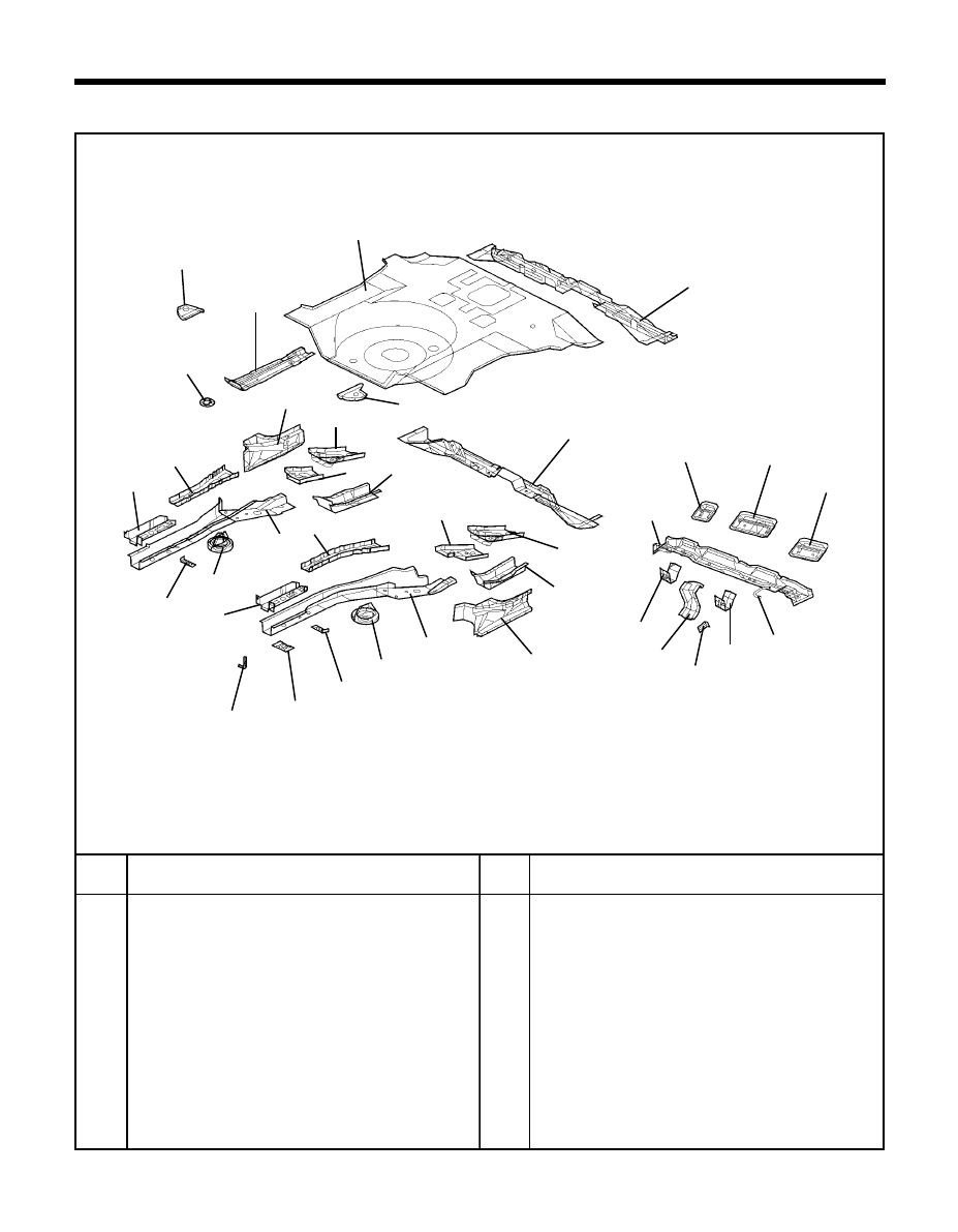
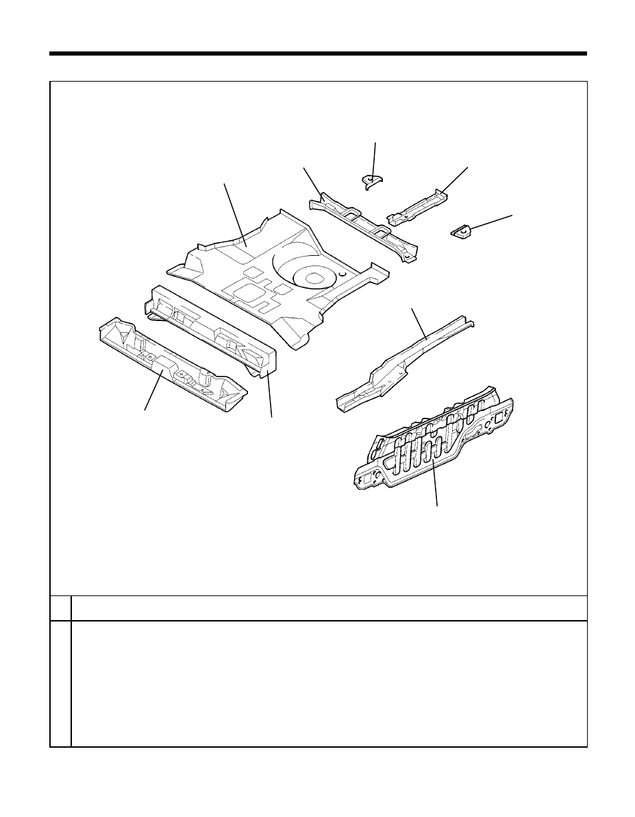
BODY CONSTRUCTION - Rear floor & side member
REAR FLOOR & SIDE MEMBER
1
6
13
10
2
4
11
6
9
7
2
12
No
TB-540
Rear floor side member
LH/RH
Rear floor side front member
LH/RH
Rear floor side member extension
LH/RH
Rear floor side member reinforcement LH/RH
Trailing arm mounting reinforcement
LH/RH
Rear suspension spring reinforcement LH/RH
Trim & net mounting front bracket
LH/RH
Trim & net mounting rear bracket
Muffler hanger mounting rear hook
Side sill inner rear extension
LH/RH
Trailing arm bracket
LH/RH
Rear floor front cross member
LH/RH
Rear floor panel
No
PART NAME
Spare tire mounting bracket
Rear towing hook bracket
Rear floor gusset
LH/RH
Rear floor extension
Rear floor center cross member
Rear seat rear bracket
LH
Rear seat rear center bracket
Rear seat rear bracket
RH
Fuel tank mounting rear bracket
LH/RH
Muffler hanger hook
Brake hose mounting bracket
Rear floor support bracket
1
2
3
4
5
6
7
8
9
10
11
12
13
14
15
16
17
18
19
20
21
22
23
24
25
PART NAME
16
15
17
19
20
21
23
22
24
25
22
1
5
5
8
16
10
14
4
3
3
7
18
11
39
BODY CONSTRUCTION - Rear floor
TB-550
<Cross-Sectional Views>
1. REAR FLOOR
SECTION B-B'
SECTION A-A'
550-1
550-3
550-2
SECTION C-C'
Rear floor panel
Rear floor extension
Rear under floor
member
Rear floor side
member
Rear floor panel
Wheel house inner
panel
Spare tire mounting bracket
A
A'
C'
B'
C
B
Rear floor panel
Rear towing hook bracket
Ó
Ó
Ó
Ó
Ó
Ó
40
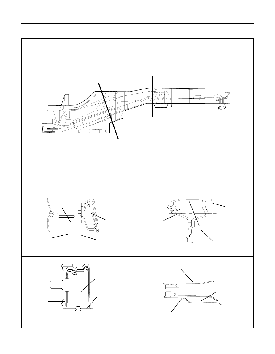
SECTION B-B'
BODY CONSTRUCTION - Rear floor side member
2. REAR FLOOR SIDE MEMBER
600-2
SECTION D-D'
SECTION C-C'
TB-600
SECTION A-A'
600-1
600-4
Side sill inner
extension
Rear floor front cross member
Rear floor side
member
Rear floor side
front member
Trailing arm mounting
reinforcement
Rear floor side
member
Side sill inner
rear extension
Trailing arm bracket
Rear floor side member
reinforcement
Rear floor side member
Rear suspension
spring reinforcement
600-3
Rear floor panel
Rear floor side
member extension
Rear floor side member
Trim & net mounting
rear bracket
B'
B
A'
A
Ó
Ó
C'
C
Ó
Ó
D'
D
Ó
Ó
Ó
Ó
41
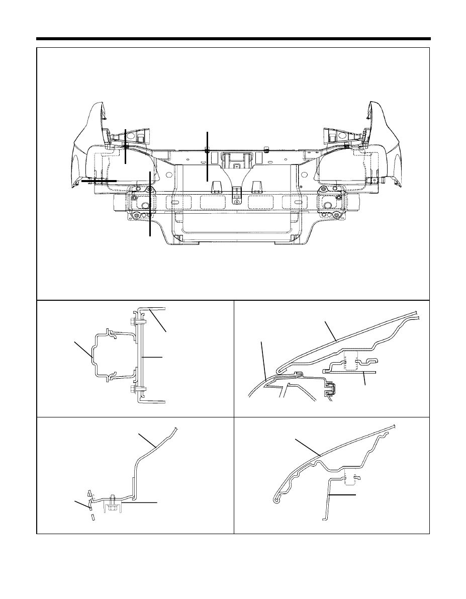
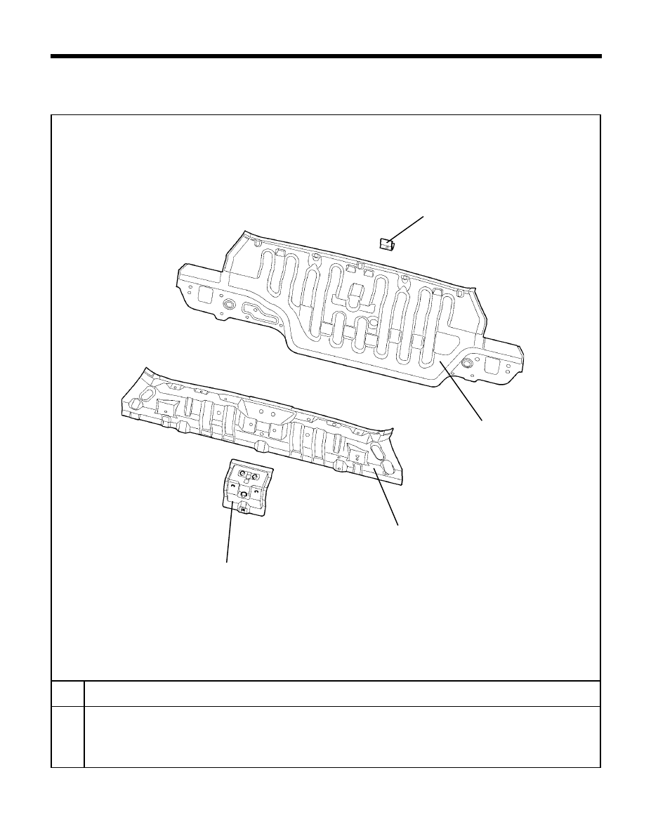
BODY CONSTRUCTION - Rear body < Back panel>
REAR BODY
BACK PANEL
No
PART NAME
Tail gate striker reinforcement assembly
Rear transverse member
Back panel
Rear bumper cover lower mounting bracket
1
2
3
4
TB-650
1
2
3
4
42
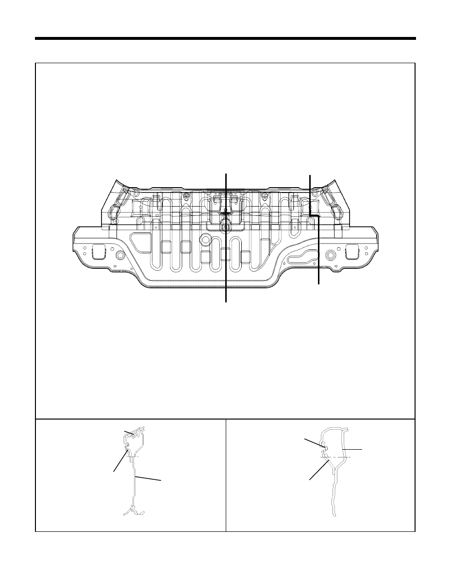
SECTION B-B'
SECTION A-A'
BODY CONSTRUCTION - Rear body <Back panel>
660-1
660-2
TB-0660
Tail gate striker reinforcement
Rear transverse member
Back panel
Child restraint anchor
reinforcement
Rear transverse member
<Cross-sectional Views>
A'
A
B'
B
Í
Í
Í
Í
Back panel
43
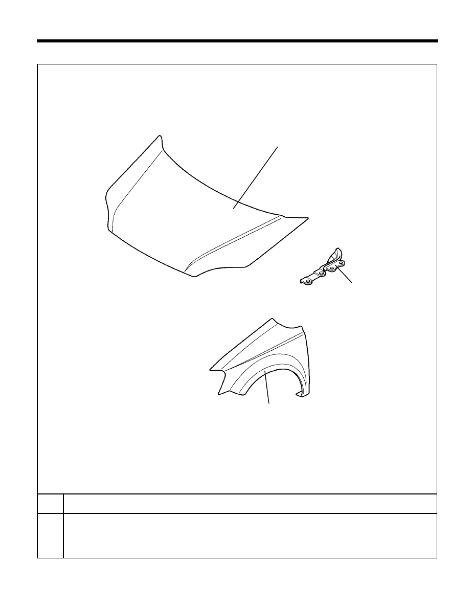
BODY CONSTRUCTION - Fender & Hood
FENDER & HOOD
No
1
Hood panel
2
Hinge hood side reinforcement
LH/RH
3
Fender panel
LH/RH
PART NAME
TB-690
1
3
2
44
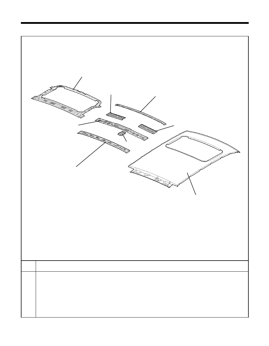
BODY CONSTRUCTION - Roof
ROOF
NO
1
2
3
4
5
6
7
8
PART NAME
Roof panel
Roof center front rail
Roof center side rail
LH
Roof center side rail
RH
Roof center rail
Room lamp mounting bracket assembly
Roof center rear rail
Sunroof reinforcement ring assembly
TB-700
3
5
4
6
1
2
8
7
45
SECTION D-D'
SECTION B-B'
SECTION C-C'
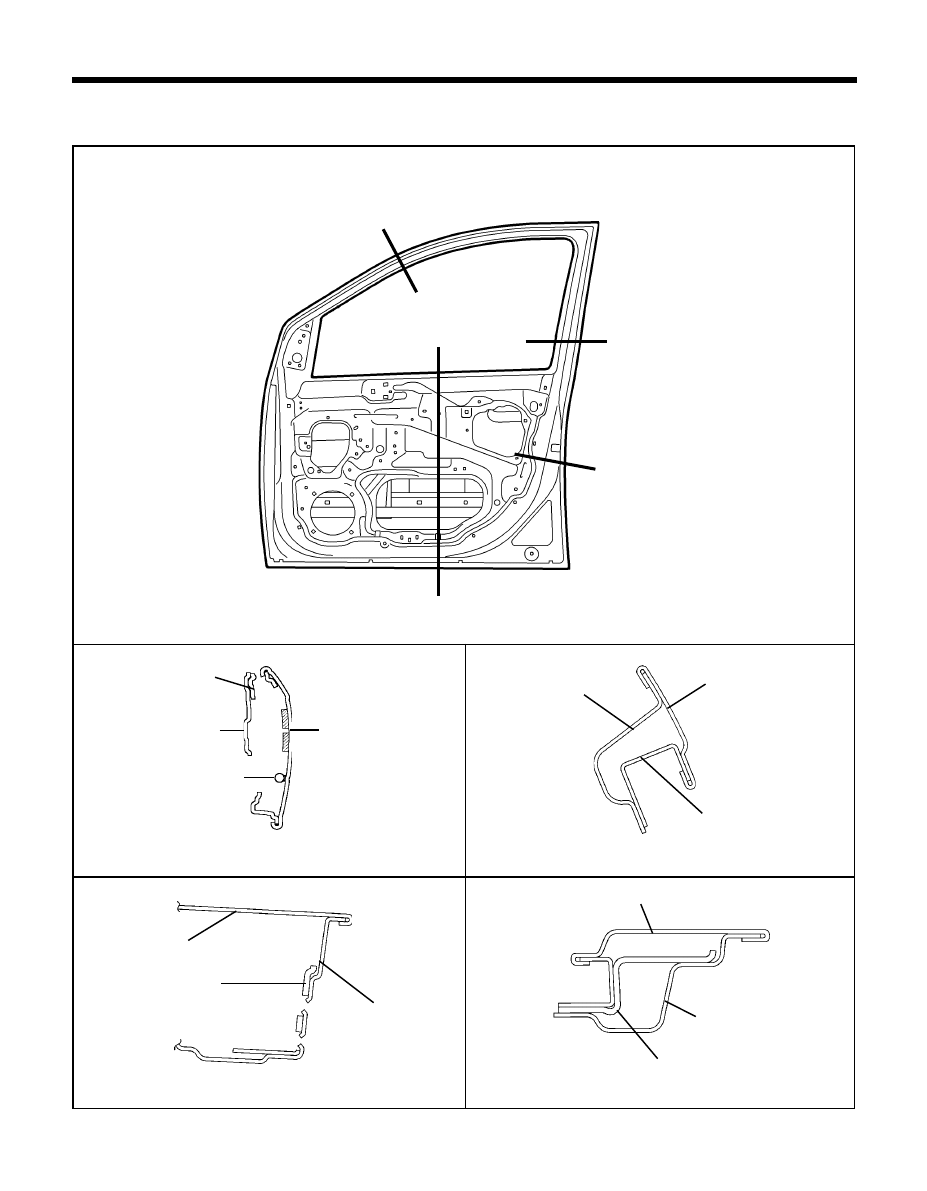
BODY CONSTRUCTION - Door <Front door>
710-4
710-3
DOOR
1. FRONT DOOR
SECTION A-A'
710-1
710-2
TB-710
Front door inner
panel
Front door inner member
Front door outer panel
Front door inner panel
Front door channel
& reinforcement
Front door outer panel
<Cross-sectional Views>
Front door outer panel
Front door channel
& reinforcement
Front door inner panel
Front door reinforcement
beam
Front door outer panel
Front door channel
& reinforcement
Front door channel & reinforcement
Î
Î
A'
A
B'
B
Ó
D'
D
Í
Í
C'
C
Í
Ó
Í
46
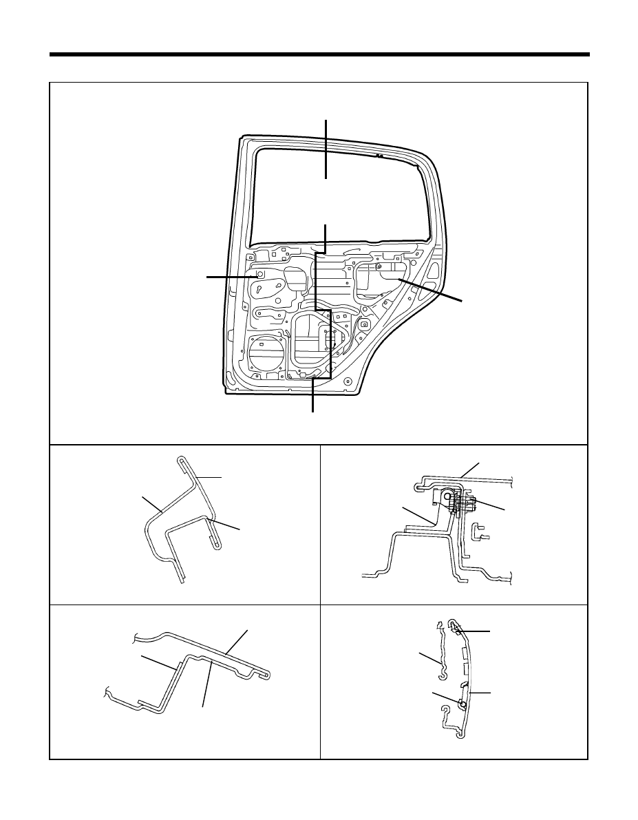
SECTION C-C'
SECTION D-D'
SECTION B-B'
SECTION A-A'
BODY CONSTRUCTION - Door<Rear door>
760-4
760-3
760-1
760-2
TB-760
Rear door outer panel
Rear door channel
reinforcement
Rear door inner panel
Rear door inner panel
Rear door reinforcement beam
Rear door outer panel
Rear door outer panel
Rear door panel
Rear door upper hinge
2. REAR DOOR
<Cross-sectional Views>
Rear door channel
& reinforcement
Rear door inner
panel
Door side hinge
mounting bolt
Rear door channel
& reinforcement
A'
Í
Í
A
B'
Í
B
C
C'
Ó
Í
D
D'
Ó
Í
Í
47
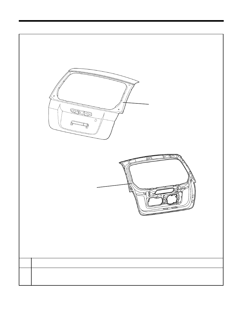
BODY CONSTRUCTION - Tail gate
NO
1
2
PART TIME
Tail gate outer panel
Tail gate inner panel
TB-800A/B
TAIL GATE
1
2

REPLACEMENT
PARTS
50
REPLACEMENT PARTS - Front body
REPLACEMENT PARTS
The following section illustrates replacement parts used in the repairs described in this manual. It is important that only
Hyundai replacement parts be used in making these repairs to ensure the repairs are made with the highest possible
standards for fit, safety and corrosion protection.
For a more complete listing of service parts, refer to an authorized Hyundai dealership.
FRONT BODY
A
B
C
D
E
RADIATOR SUPPORT COMPLETE MEMBER ASSEMBLY
FRONT SIDE MEMBER ASSEMBLY,
LH/RH
FENDER APRON PANEL ASSEMBLY,
LH/RH
DASH PANEL COMPLETE
COWL PANEL ASSEMBLY
PART NAME
TB-60
C
B
D
A
E
51
REPLACEMENT PARTS - Side body
SIDE BODY
PART NAME
FENDER MOUNTING BRACKET ASSEMBLY,
LH/RH
FRONT PILLAR OUTER PANEL,
LH/RH
CENTER PILLAR OUTER ASSEMBLY,
LH/RH
QUARTER OUTER PANEL ASSEMBLY,
LH/RH
SIDE SILL OUTER PANEL,
LH/RH
SIDE INNER PANEL ASSEMBLY,
LH/RH
QUARTER INNER PANEL ASSEMBLY,
LH/RH
REAR PILLAR PANEL ASSEMBLY,
LH/RH
QUARTER OUTER REAR LOWER EXTENSION ASSEMBLY, LH/RH
QUARTER OUTER PANEL ASSEMBLY, 3DOOR
LH/RH
(3 DOOR)
A
B
C
D
E
F
G
H
I
J
TB-800C
C
B
A
D
E
F
G
J
I
H
52
REPLACEMENT PARTS - Rear body
REAR BODY
A
B
C
D
E
F
G
H
REAR FLOOR FRONT MEMBER ASSEMBLY
REAR FLOOR FRONT EXTENSIOR ASSEMBLY
REAR FLOOR PANEL
REAR FLOOR SIDE COMPLETE MEMBER ASSEMBLY,
LH/RH
REAR FLOOR CENTER CROSS MEMBER ASSEMBLY
GUSSET,
LH/RH
REAR TOWING HOOK BRACKET ASSEMBLY
BACK PANEL ASSEMBLY
PART NAME
TB-830
C
B
A
E
D
F
G
F
H
53
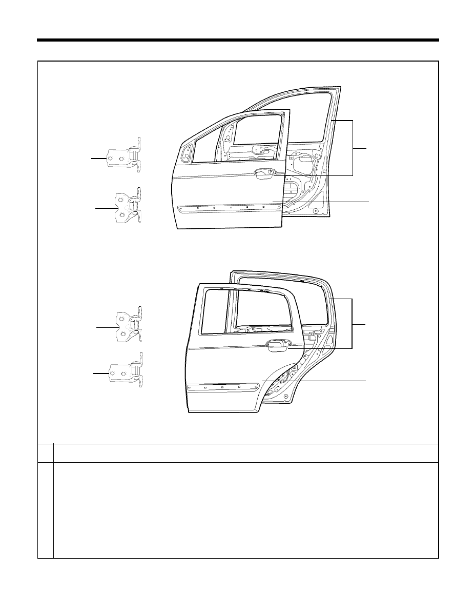
REPLACEMENT PARTS - Door
DOOR
A
B
C
D
E
F
G
H
FRONT DOOR PANEL ASSEMBLY,
LH/RH
FRONT DOOR OUTER PANEL,
LH/RH
FRONT DOOR UPPER HINGE ASSEMBLY,
LH/RH
FRONT DOOR LOWER HINGE ASSEMBLY,
LH/RH
REAR DOOR PANEL ASSEMBLY,
LH/RH
REAR DOOR OUTER PANEL,
LH/RH
REAR DOOR UPPER HINGE ASSEMBLY, LH/RH
REAR DOOR LOWER HINGE ASSEMBLY, LH/RH
PART NAME
TB-7113,7112/TB-RR
TB-7112,113/TB-FRT
A
C
D
H
G
B
E
F

BODY
DIMENSIONS
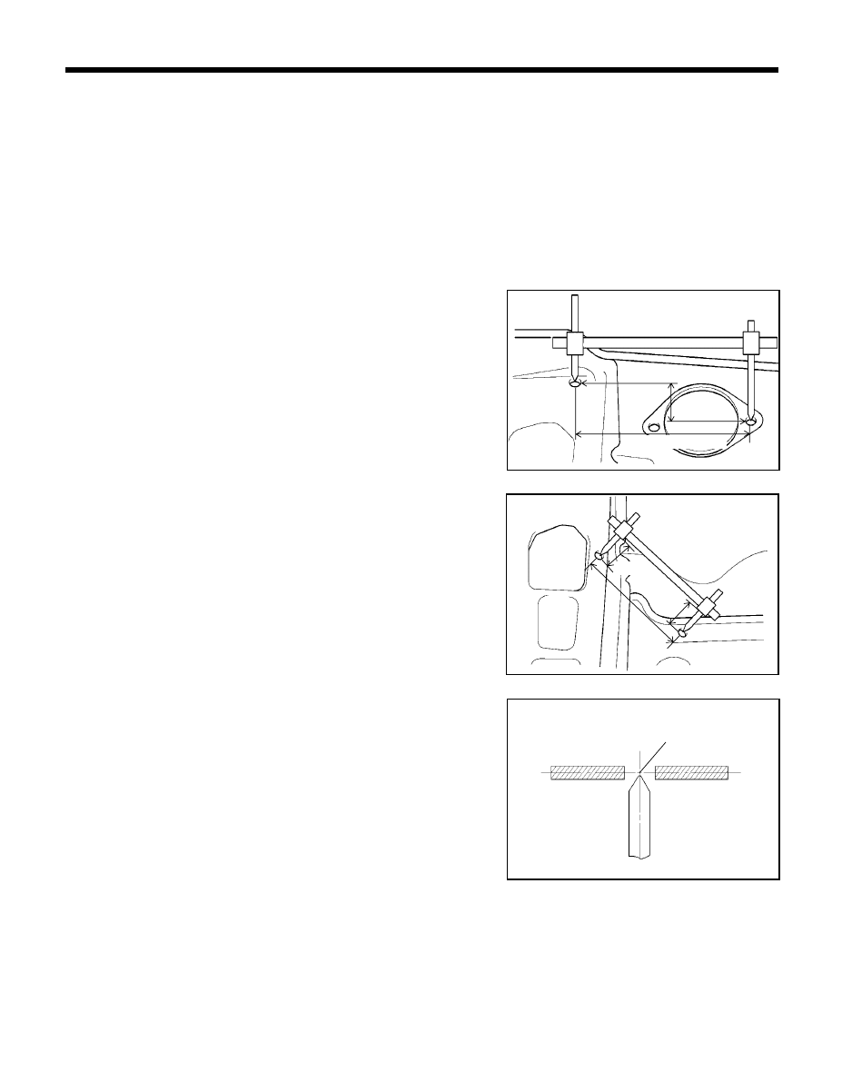
56
GENERAL
1.
Basically, all measurements in this manual are taken with a
tracking gauge.
2.
When a measuring tape is used, check to be sure there is no
elongation, twisting or bending.
3.
For measuring dimensions, both projected dimension and ac-
tual-measurement dimension are used in this manual.
ACTUAL-MEASUREMENT DIMENSIONS
1.
These dimensions indicate the actual linear distance between
measurement points, and are the reference dimensions for use
if a tracking gauge is used for measurement.
2.
Measure by first adjusting both probes to the same length (A=A')
NOTE
Check the probes and gauge itself to make sure there is no
free play.
MEASUREMENT POINT
1.
Measurements should be taken at the hole center.
MEASUREMENT METHOD
PROJECTED DIMENSIONS
1.
These are the dimensions measured when the measurement
points are projected into the reference plane, and are the
reference dimensions used for body alterations.
2.
If the length of the tracking gauge probes are adjustable, make
the measurement by lengthening one probe by the amount
equivalent to the difference in height of the two surfaces.
Actually-measured dimension
BODY DIMENSIONS - General
A'
DIM0010
DIM0020
DIM0030
Height
Hole center
Projected dimension
A
A'
57
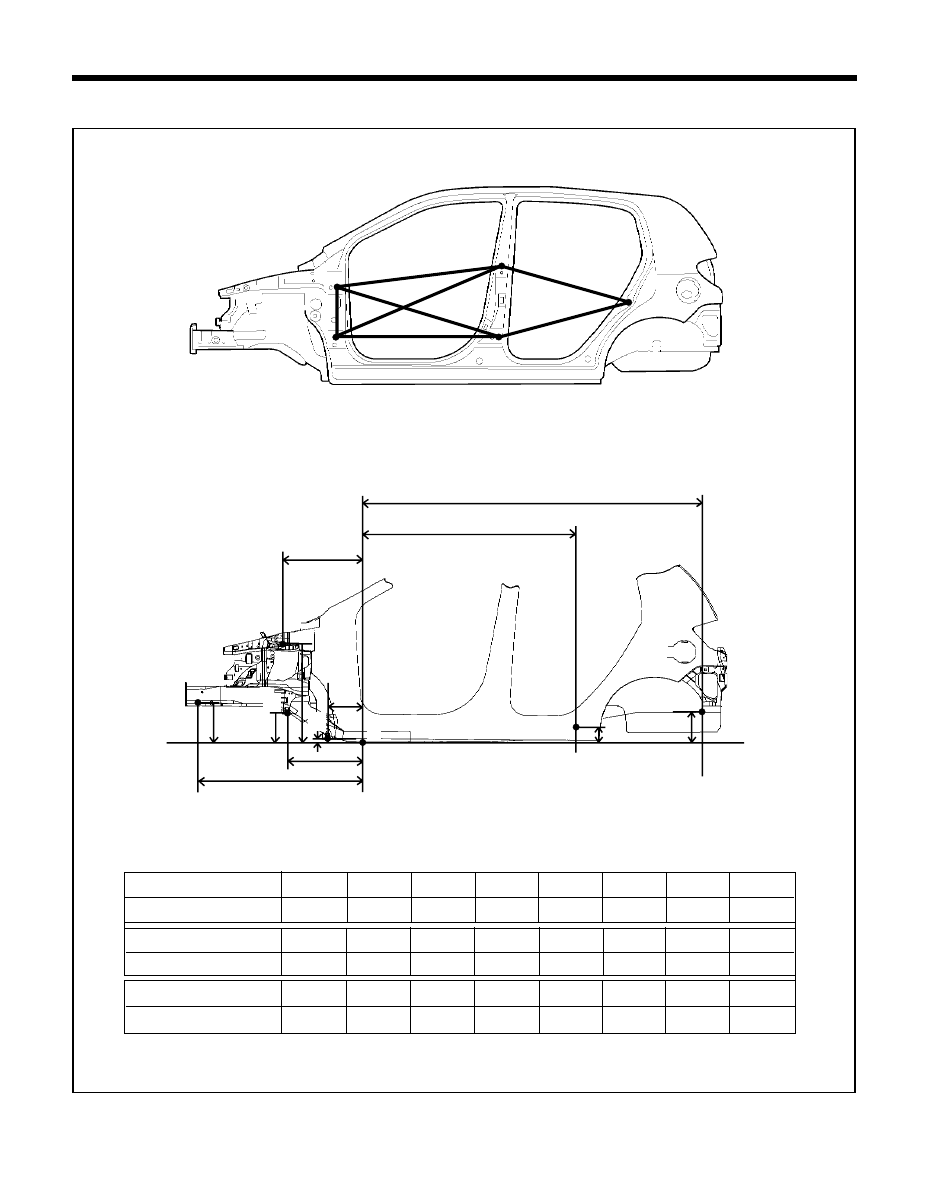
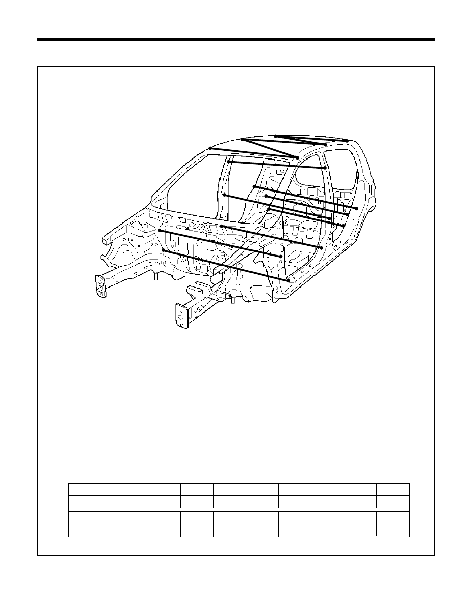
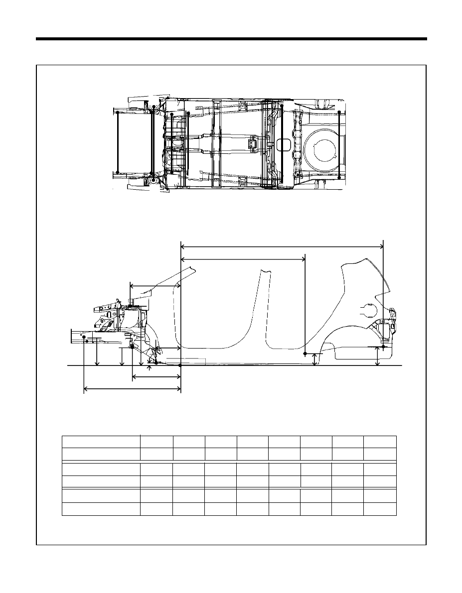
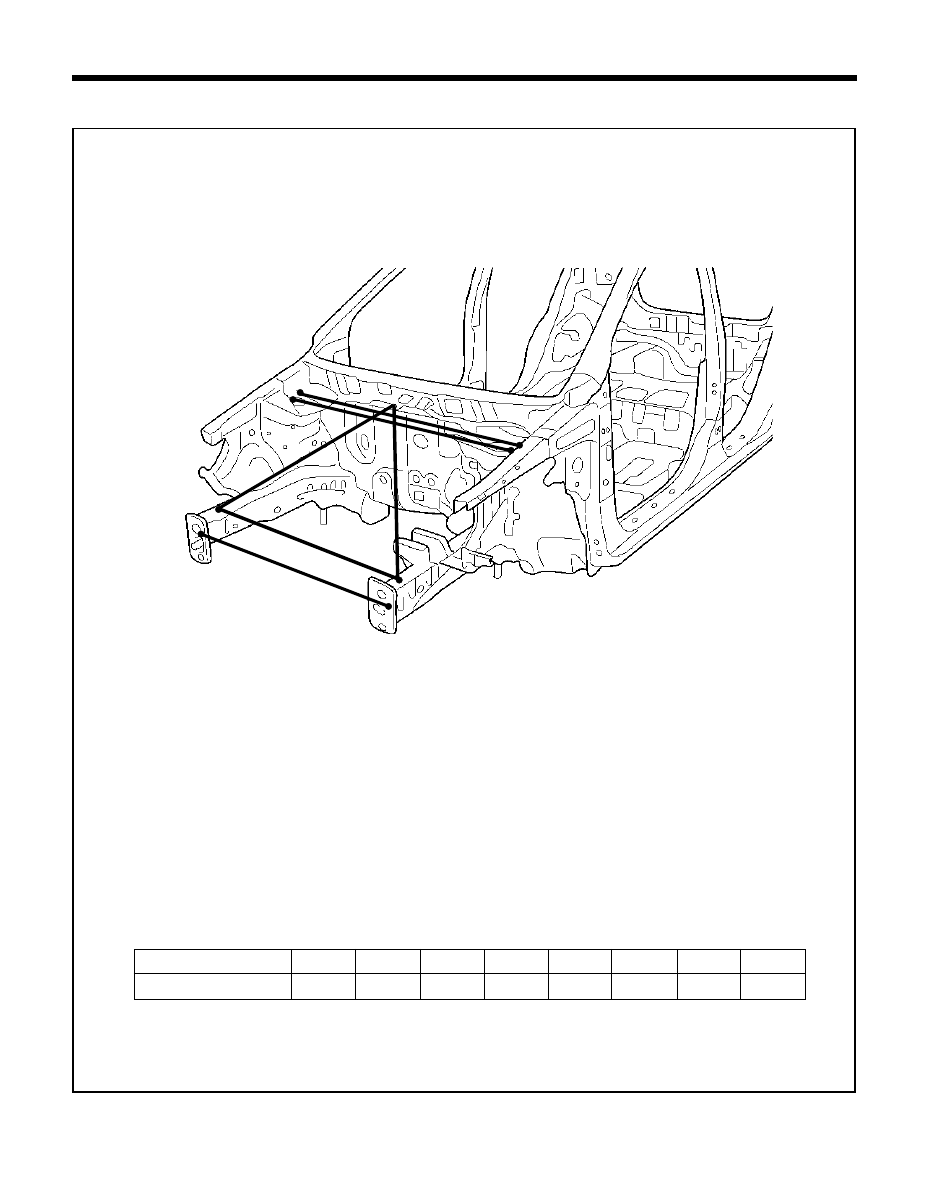
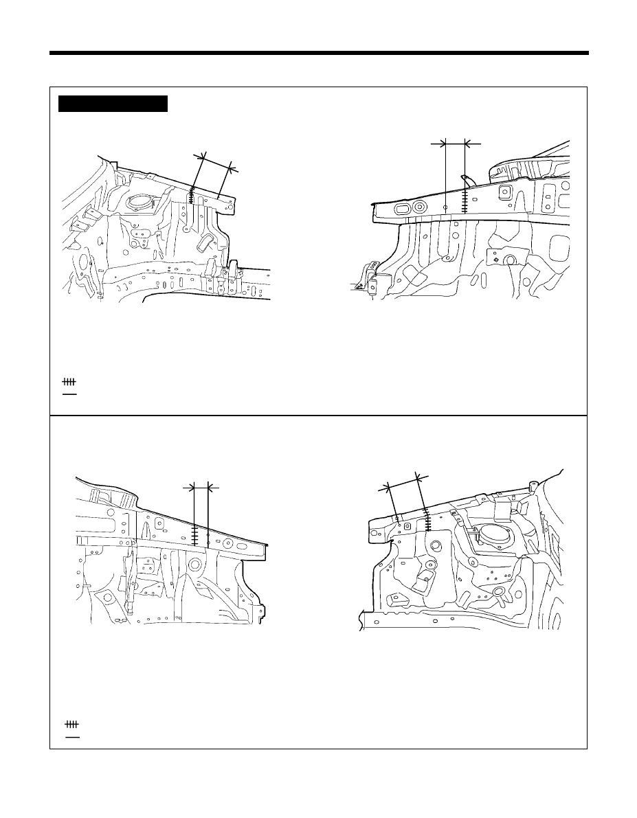
UPPER BODY
Point symbol
Length (mm)
C-C'
C-E'
E-F'
E-E'
D-D'
A-A'
A'-C
B-B'
* These dimensions indicated in this figure are actual-measurement dimensions.
TB-53
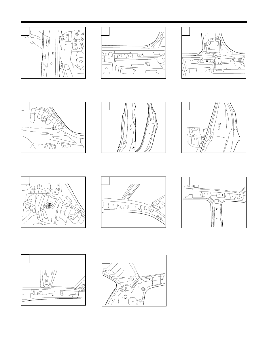
BODY DIMENSIONS - Upper body
A'
A
B'
C'
E'
F
B
C
E
D'
D
1282
1264
1304
1134
1510
1272
1057
1839
58
A
F
54-B
54-C
D
E
54-E
54-G
Ó
Ó
Ò
Ï
C
B
Ó Ó Ó Ó Ó
Ó Ó Ó Ó Ó
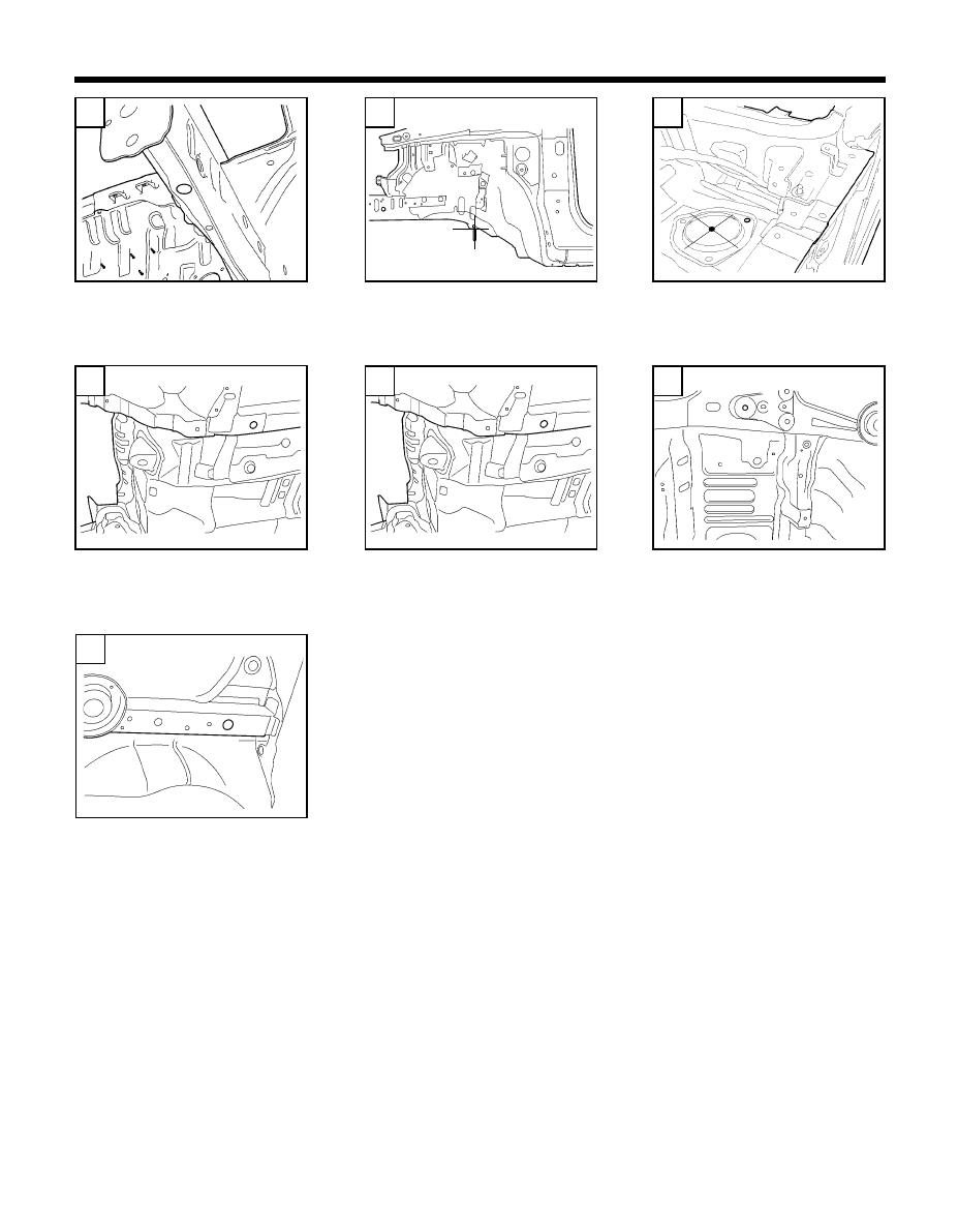
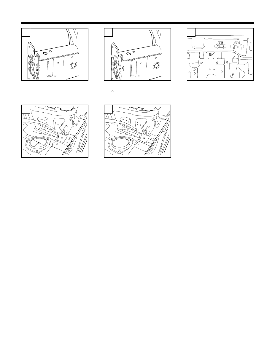
BODY DIMENSIONS - Upper body
Fender center mounting hole
(Ø
6.6)
Front shock absorber mounting
hole (Ø
9)
Hood hinge mounting hole
(
Ø
13)
Joint of roof panel and front pillar
Joint of quarter and roof panel
54-A
54-D
Fender front mounting hole
(Ø
6.6)
59
SIDE BODY
55-A
BODY DIMENSIONS - Side body
Length (mm)
Point symbol
B-C
A-C
A -D
B-D
C-E
D-E
F-M
A-B
Point symbol
H-M
I-M
I-J
H-J
G-M
J-K
Length (mm)
Point symbol
G-J
J-L
Length (mm)
L-M
*These dimensions indicated in this figure are projected dimensions.
*These dimensions indicated in this figure are actual-measurement dimensions.
TB-55B
315
A
B
D
C
E
G
F
H
K
L
M
F-J
K-M
1044
1071
1100
1026
865
924
950
244
490
646
464
177
198
15
1449
2230
64
206
I
J
60
A
B
D
56-D
E
56-E
F
56-F
G
56-G
H
56-H
56-I
C
Ñ
Í
Í
Í
Í
Í
Ñ
Ô
Ñ
Ñ
K
L
Í
Í
Í
Í
Í
Ñ
Ñ
Ñ
Ñ
Ñ
I
Front door hinge upper mounting
hole (Ø
12)
Front door hinge lower mounting
hole (Ø
12)
Rear door hinge upper mounting
hole (Ø
12)
Rear door hinge lower mounting
hole (Ø
12)
Rear door striker mounting hole
(Ø
13)
Tooling hole
(Ø
25)
Front shock absorber mounting
hole (Ø
89)
Cross member mounting front
hole (Ø
14.2)
Cross member mounting rear hole
(Ø
16)
Tooling hole
(
Ø
25)
Rear trailing arm mounting hole
(
Ø
13)
Tooling hole
(
Ø
25)
BODY DIMENSIONS - Side body
Ï
Ï
56-B
56-C
56-J
56-L
56-A
Ñ
54-C
J
Ñ
61
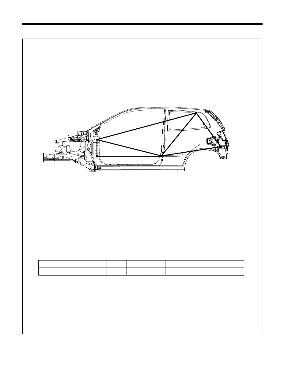
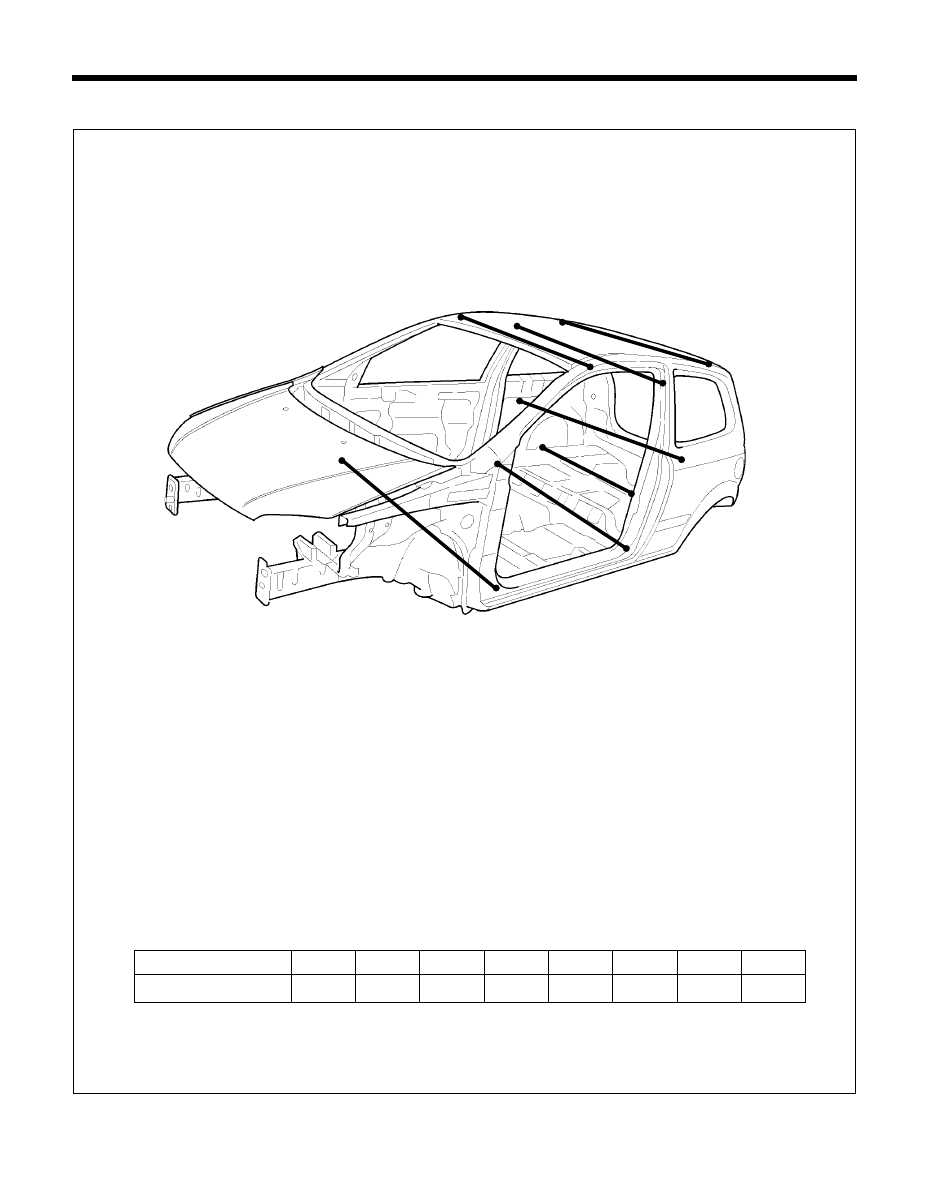
SIDE BODY (3 DOOR)
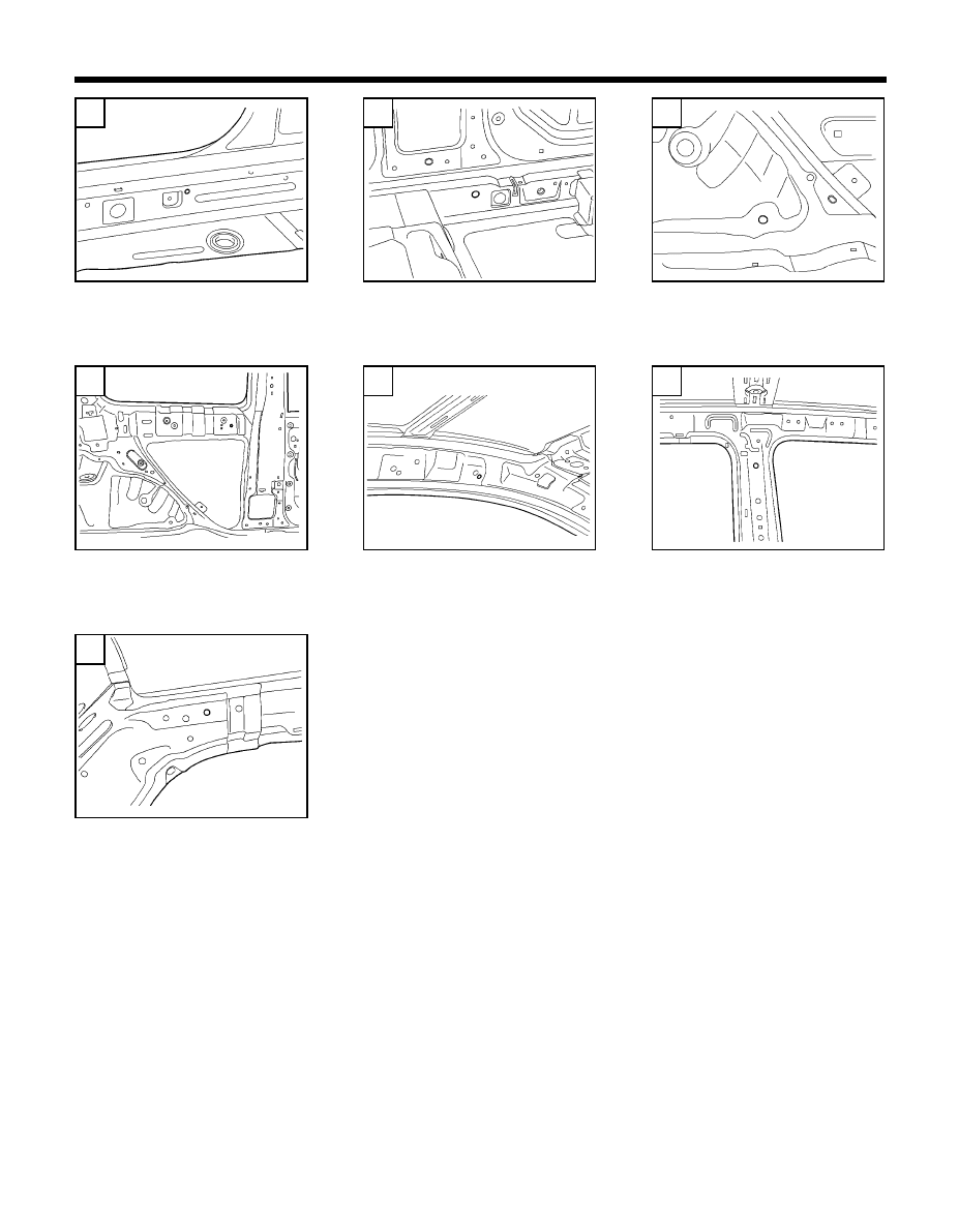
BODY DIMENSIONS - Side body (3 Door)
Point symbol
C-D
A-C
B -C
C-E
A-B
Length (mm)
*These dimensions indicated in this figure are actual-measurement dimensions.
3DOOR SIDE
315
D
E
C
A
B
1235
1221
1003
1150
A-D
D-E
1985
792
62
A
B
D
3SC
E
3SD
C
Ñ
ÍÍÍÍÍ
Í
Í
Í
Í
Í
Ñ
Ñ
Ñ
Ñ
Ñ
Front door hinge upper mounting
hole (Ø
12)
Front door hinge lower mounting
hole (Ø
12)
Front door switch hole
(Ø
10)
Side outer rear glass fixing hole
( 8 12 slot )
Rear bumper cover mounting hole
( 10 12)
BODY DIMENSIONS - Side body (3 Door)
Ï
56-B
3SB
56-A
63
INTERIOR
Point symbol
Length (mm)
Point symbol
Length (mm)
D-D'
E-E'
H-J'
H-H'
G-G'
F-F'
A-A'
B-B'
I-I'
C-C'
* These dimensions indicated in this figure are actual-measurement dimensions.
58
BODY DIMENSIONS - Interior
1393
K'
J'
H'
I'
F'
E'
C'
A'
B'
B
A
C
D
E
G
F
D'
G'
I
H
J
K
J-K'
J-J'
K-K'
1263
1255
1139
1431
1437
1117
1057
1369
1131
1055
1082
1030
64
A
F
59-B
59-C
D
E
59-E
59-F
Ó
Ó
Ò
Ï
C
B
ÓÓÓÓÓ
Ó Ó Ó Ó Ó
G
Ó Ó Ó Ó Ó
I
H
Ï
Ï
Ï
Ï
Ï
Ð Ð Ð Ð Ð
BODY DIMENSIONS - Interior
Door scuff mounting hole
(
Ø
7)
Front seat belt mounting hole
(
Ø
16)
Rear seat belt lower mounting
hole (
Ø
13.2)
Front door striker mounting hole
(
Ø
13)
Rear door striker mounting hole
(
Ø
13)
Rear suspension mounting hole
(
Ø
20.5)
Roof rack mounting hole
(
Ø
9)
Front seat belt anchor mounting
hole (
Ø
15)
59-A
59-D
59-G
59-I
59-H
J
Ñ
K
Rear assist handle mounting hole
(Ø
6.6)
Sun roof drain hose mounting
hole
(
Ø
14)
59-J
59-K
Ñ
Front door checker mounting hole
(
Ø
14)
65
INTERIOR (3 DOOR)
Point symbol
Length (mm)
E-E'
F-F'
G-G'
A-A'
B-B'
C-C'
* These dimensions indicated in this figure are actual-measurement dimensions.
3DOOR INTERIOR
BODY DIMENSIONS - Interior (3 Door)
1263
G'
G
F'
E'
E
F
D'
B
D
C'
C
B'
A'
A
D-D'
1255
1139
1373
1057
1125
1030
66
A
F
3IB
3IC
D
E
3IF
Ó
Ó
Ò
Ï
C
B
ÓÓÓÓÓ
Ó Ó Ó Ó Ó
G
Ó Ó Ó Ó Ó
BODY DIMENSIONS - Interior (3 Door)
Front seat belt mounting hole
(
Ø
15)
Rear seat back mounting hole
(
Ø
13.2)
Tooling hole
(
Ø
12)
Roof rack mounting hole
(
Ø
9)
Front seat belt anchor mounting
hole (
Ø
15)
Sun roof drain hose mounting
hole
(
Ø
14)
Door scuff mounting hole
(
Ø
7)
3IA
3ID
3IG
3IE
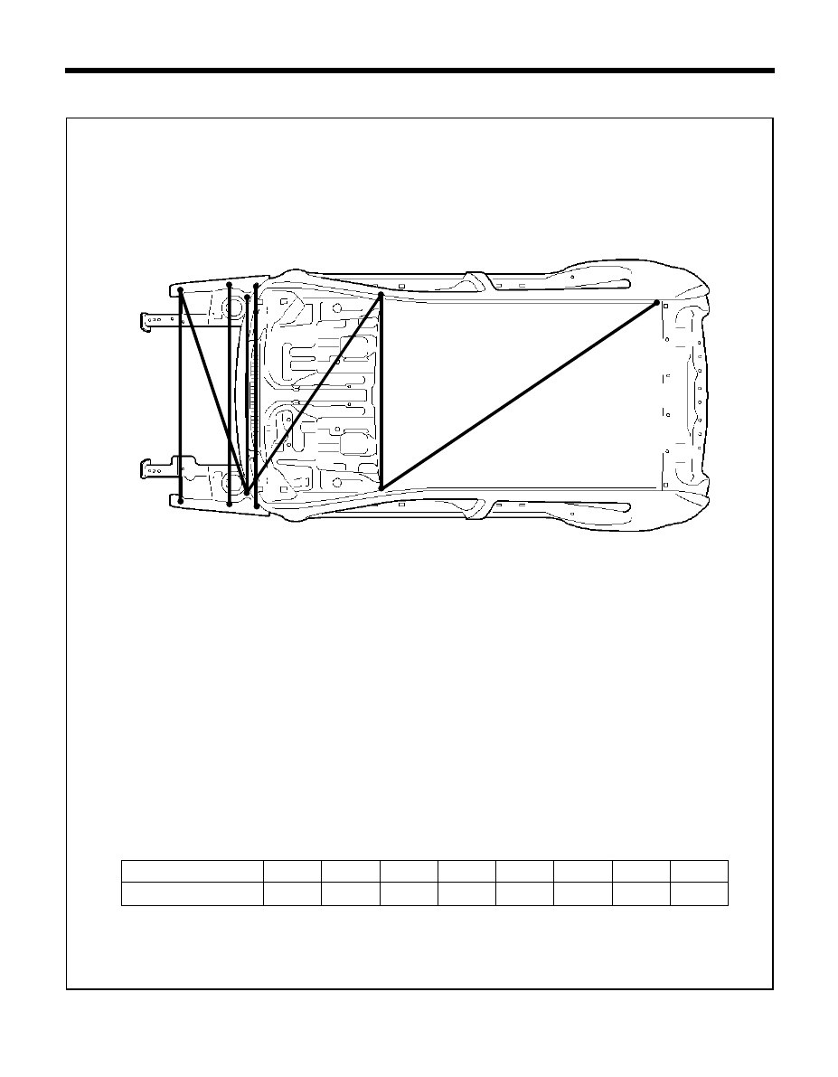
67
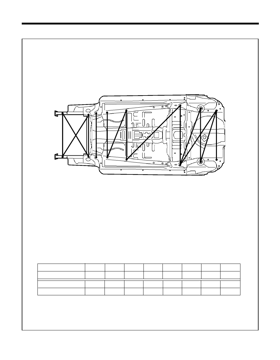
UNDER BODY
TB-60A
BODY DIMENSIONS - Under body
Point symbol
D-D'
B-B'
C-C'
E-E'
F-F'
G-G'
A-H
A-A'
Point symbol
F-H
A-E
G-H
D-H
C-H
C-E
Length (mm)
B-H
D-E
E-F
E-G
Length (mm)
B-E
*These dimensions indicated in this figure are projected dimensions.
*These dimensions indicated in this figure are actual-measurement dimensions.
940
TB-55B
G'
G
F'
F
E
E'
B'
D
C'
D'
A'
C
B
A
H
A
B
E
F
G
Point symbol
Length (mm)
920
1066
880
914
1149
970
244
177
646
15
64
206.2
950
464
490
198
1449
2230
C
D
68
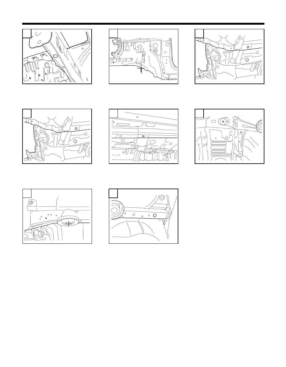
A
B
D
E
F
G
56-L
C
Ñ
Tooling hole
(
Ø
25)
Cross member mounting front
hole (
Ø
14)
Front shock absorber mounting
hole (
Ø
89)
Cross member mounting rear
hole
(
Ø
16)
Tooling hole
(
Ø
25)
Trailing arm mounting hole
(
Ø
13)
Tooling hole
(
Ø
25)
BODY DIMENSIONS - Under body
56-F
Ï
56-G
Ñ
56-H
Ô
56-I
Ñ
Ñ
56-J
54-C
Ñ
69
UNDER BODY
BODY DIMENSIONS - Under body
Point symbol
B-B'
A'-B
A -B'
C-C'
D-D'
D-E'
E-E'
A-A'
Point symbol
G-G'
H-H'
G-H'
F-G'
F-F'
Length (mm)
E-F'
Length (mm)
*These dimensions indicated in this figure are actual-measurement dimensions.
940
62
A'
B' C'
D'
E'
F'
G'
H'
A
B C
D
E
F
G
H
1051
1051
920
880
914
1023
978
1502
1149
1192
1050
1065
970
F-H'
1327
70
A
B
D
56-HI
E
63-E
F
56-J
G
56-K
H
56-L
C
Ñ
Í
Í
Í
Í
Í
Ñ
Ô
Í
Í
Í
Í
Í
Ñ
ÑÑ
Ñ
Ñ
Tooling hole
(
Ø
25)
Cross member mounting front
hole (
Ø
14)
Cross member mounting rear
hole
(
Ø
16)
Trail arm mounting hole
(
Ø
13)
Rear suspension spring mounting
hole (
Ø
40)
Tooling hole
(
Ø
25)
BODY DIMENSIONS - Under body
Ï
Ï
56-F
56-G
56-HI
Tooling hole
(
Ø
25)
Tooling hole
(
Ø
18)
71
BODY DIMENSIONS - Engine compartment
ENGINE COMPARTMENT
Point symbol
Length (mm)
C-B'
D-D'
E-E'
A-A'
B-B'
C-B
* These dimensions indicated in this figure are actual-measurement dimensions.
64
1019
E'
E
A
D'
D
B
B'
A'
C
960
833
833
1066
1134
72
BODY DIMENSIONS - Engine compartment
A
65-B
65-C
D
E
54-C
Ó
Ó
Ò
Ï
C
B
Ó Ó Ó Ó Ó
Stay rod to paint hole
(12 16 solt)
Cowl under cover mounting hole
(
Ø
11)
Front shock absorber mounting
hole (
Ø
89)
Front shock absorber mounting
hole (
Ø
9)
Carrier mounting hole
(
Ø
12)
65-B
54-C
73
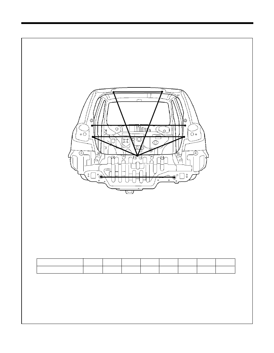
BODY DIMENSIONS - Luggage compartment
LUGGAGE COMPARTMENT
Point symbol
D-C
B-B'
C-C'
D-C'
E-E'
A-A'
Length (mm)
*These dimensions indicated in this figure are actual-measurement dimensions.
600
66
B
C'
C
B'
A'
A
E'
E
D
1019
986
514
551
806
D-A
D-A'
870
856
74
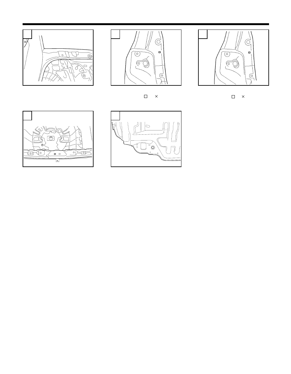
A
B
D
67-D
E
67-E
C
Ñ
ÍÍÍÍÍ
Ñ
Ñ
Ñ
Ñ
Ñ
Tail gate hinge mounting hole
(
Ø
14)
Rear combination lamp upper
mounting hole ( 8.5 8.5)
Rear combination lamp lower
mounting hole ( 8.5 8.5)
Tail gate striker mounting hole
(
Ø
13)
Tooling hole
(
Ø
20)
BODY DIMENSIONS - Luggage compartment
Ï
67-A
67-B
67-C
ÍÍÍÍÍ

BODY PANEL
REPAIR
PROCEDURE
76
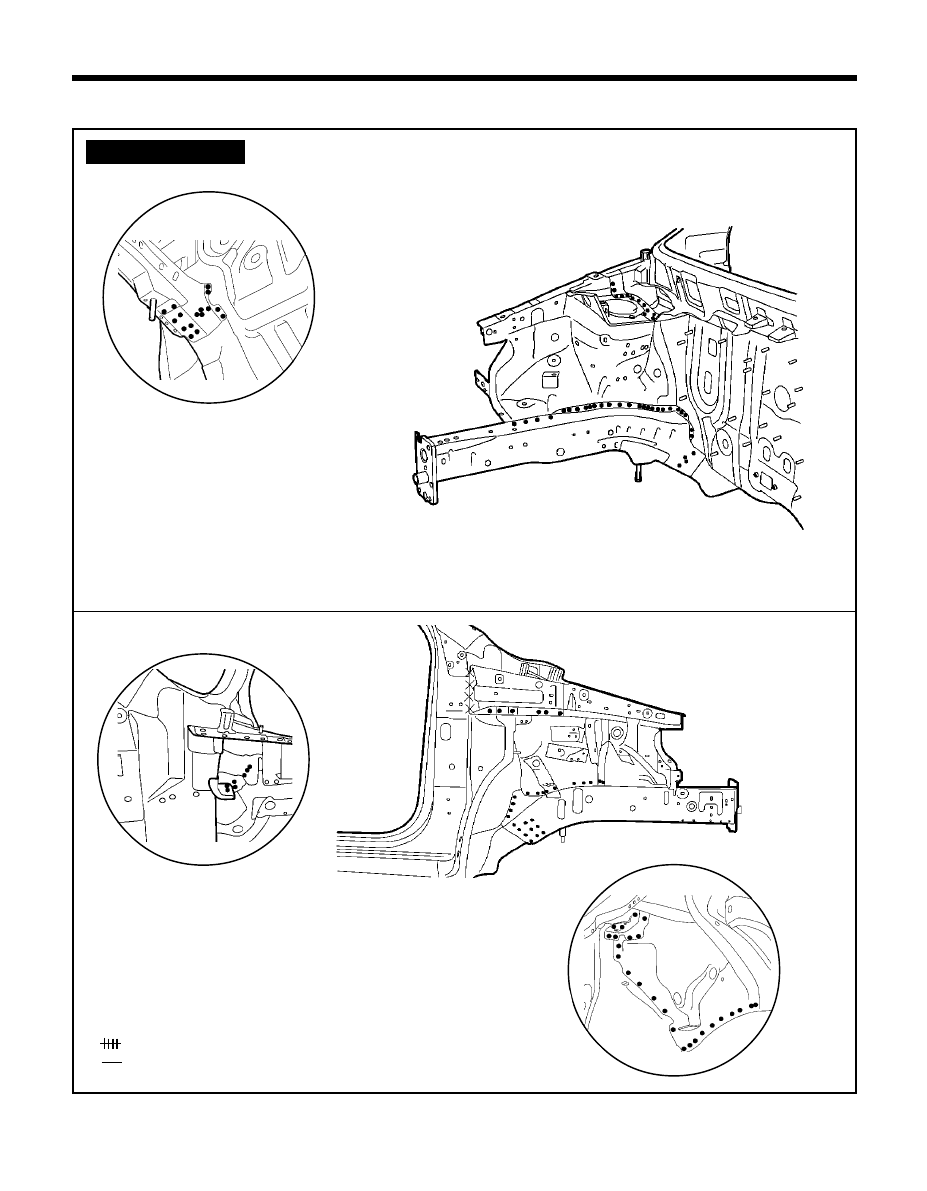
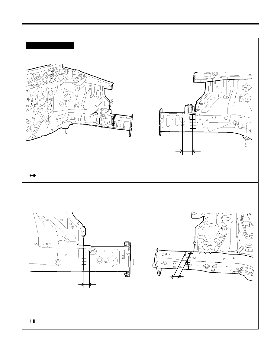
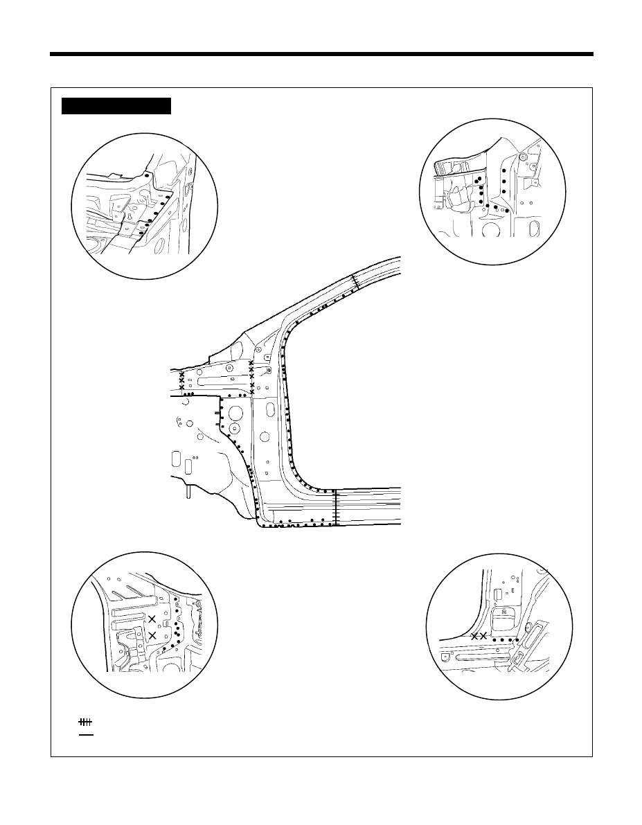
BODY PANEL REPAIR PROCEDURE - Fender apron panel (Partial)
FENDER APRON PANEL (PARTIAL)
L/H
z
z
z
z
z
MIG plug welding
MIG butt welding
xx MIG lap welding
R/H
WELDLING POINTS
PRO-0031
PRO-0040
PRO-0030
PRO-0041
50mm
120mm
120mm
50mm
z
z
z
z
z
MIG plug welding
MIG butt welding
xx MIG lap welding
77
z
z
z
z
z
MIG plug welding
MIG butt welding
xx MIG lap welding
BODY PANEL REPAIR PROCEDURE - Fender apron and front side member (Assembly)
FENDER APRON AND FRONT SIDE MEMBER (ASSEMBLY)
z
z
z
z
z
MIG plug welding
WELDLING POINTS
PRO-0050
PRO-0060
PRO-0070
PRO-0071
Ô
Ô
Ô
Ô
Ô
A
Ô
Ô
Ô
Ô
Ô
B
Ô
Ô
Ô
Ô
Ô
C
PRO-0065
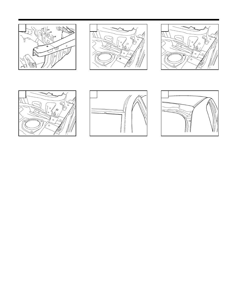
78
BODY PANEL REPAIR PROCEDURE - Fender apron and front side member (Assembly)
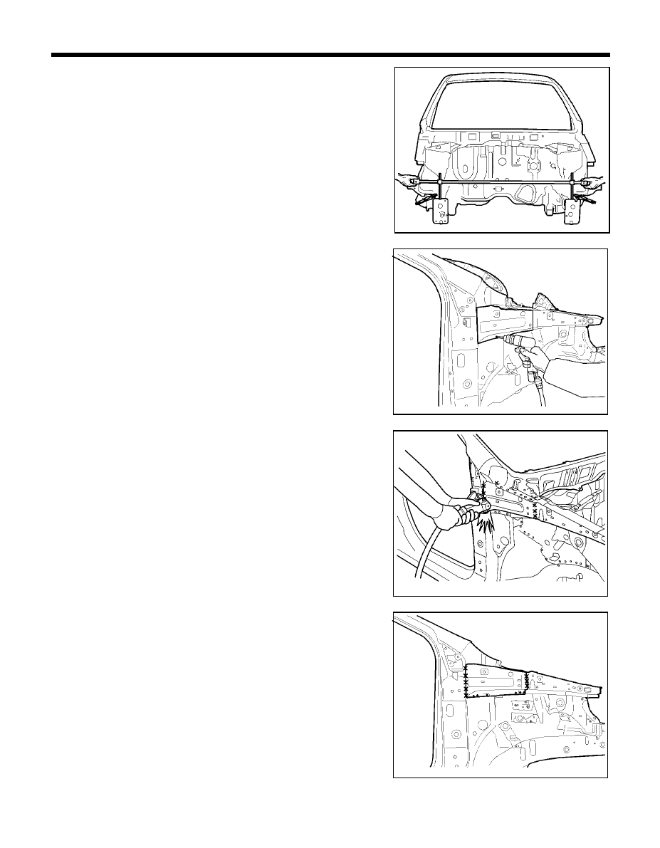
NOTE
Before repairing, remove Engine and Suspension Components.
Refer to the body dimension charts and measure the vehicle to
determine straightening and alignment requirements. The body
must be returned to its original dimension before you begin the
repair procedure.
REMOVAL
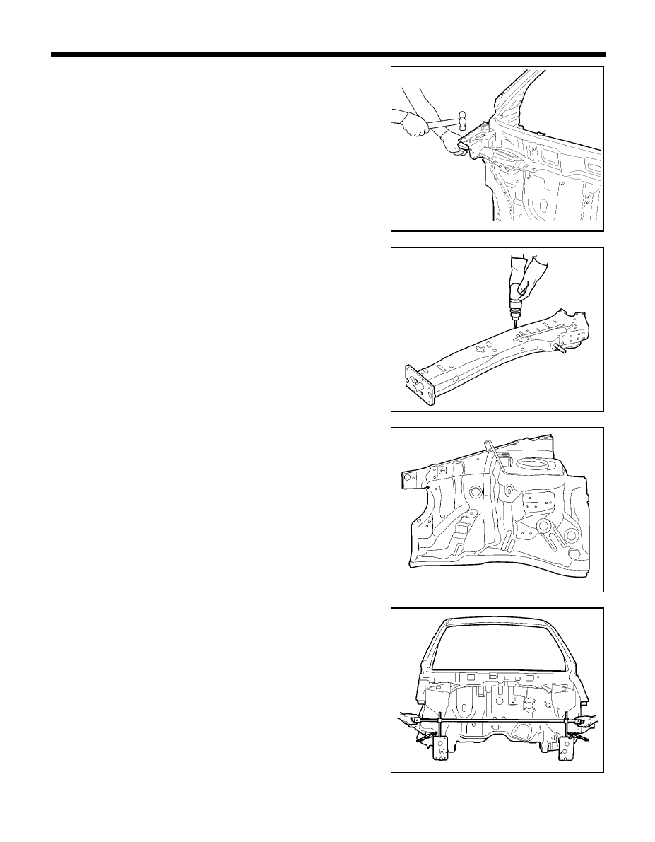
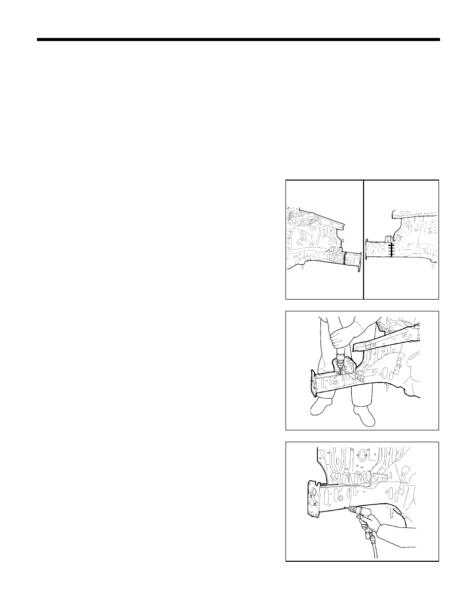
1.
Drill out all the spotwelds to separate cowl side upper outer panel
from front side member.
NOTE
When spotwelded portions are not apparent, remove paint
with a rotary wire brush.
2.
Remove Co
2
weld points using a grinder.
3.
Drill out all the spotwelds attaching the cowl side upper outer
panel.
NOTE
If it is possible that the cowl side upper outer panel is
reusable, be careful not to damage it while removing.
PRO-0100
PRO-0120
PRO-0110
PRO-0130
79
BODY PANEL REPAIR PROCEDURE - Fender apron and front side member (Assembly)
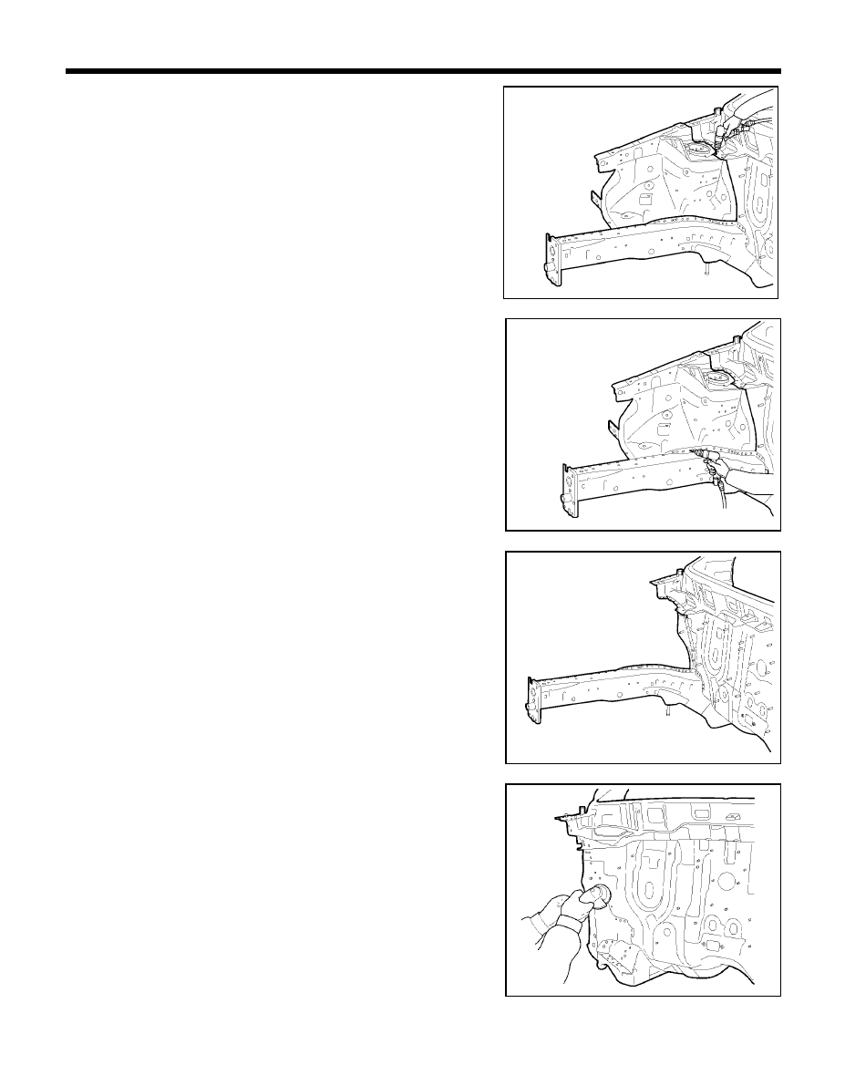
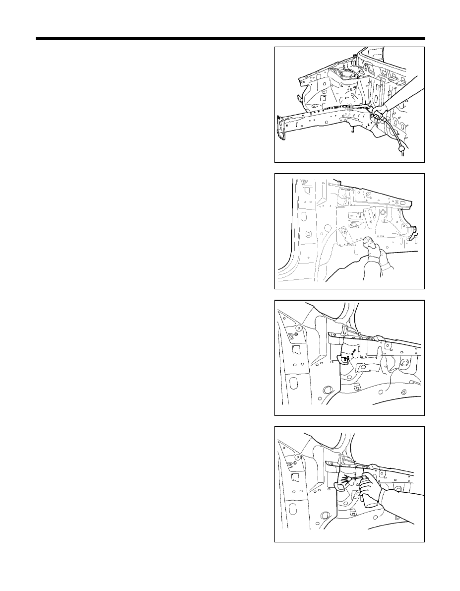
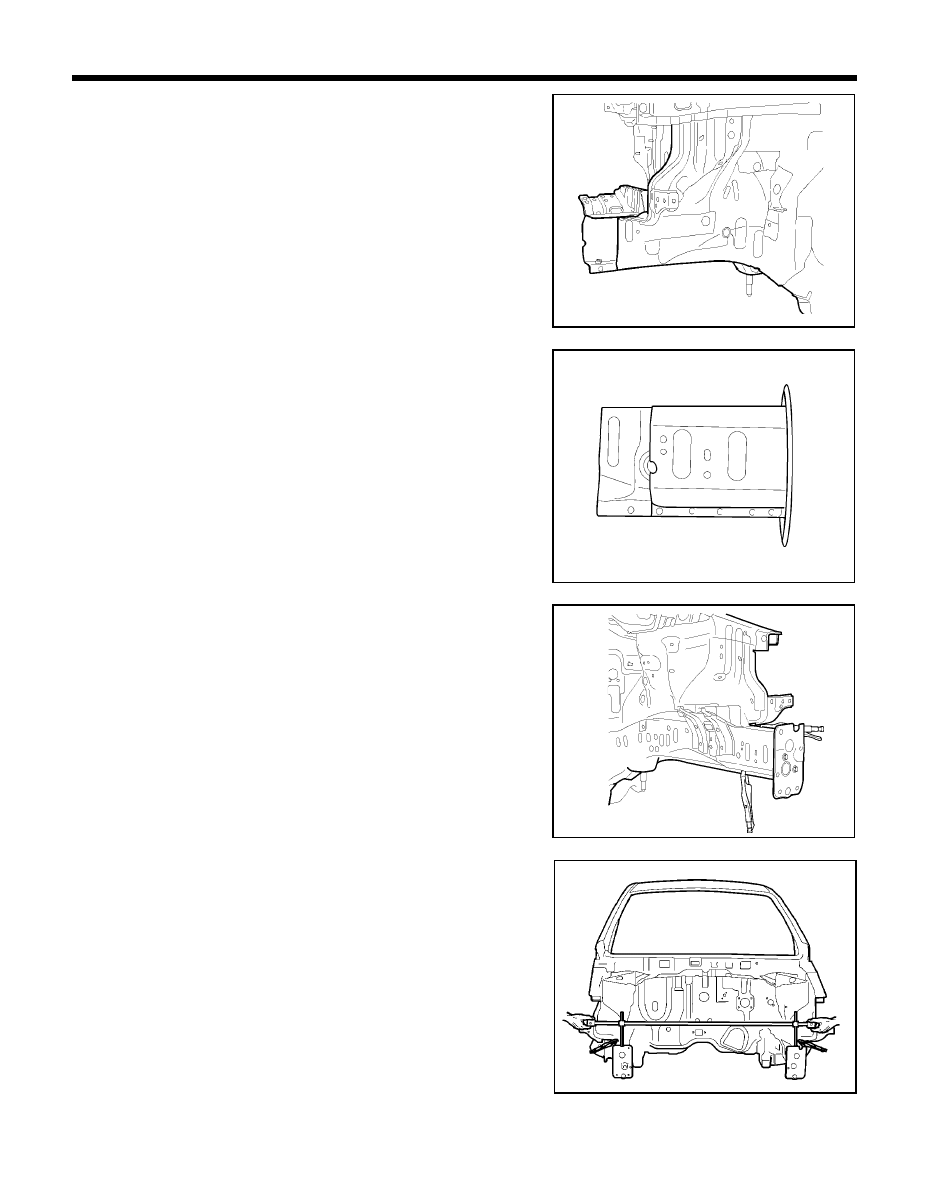
6.
Using a spotweld cutter, remove the front side member by drilling
out the spotwelds.
7.
Grind and smooth any weld traces which might be left on the body
surface by using an air grinder or similar tool, being careful not to
damage any of the panels which is not to be replaced.
4.
Using a spotweld cutter, drill out all the spotwelds attaching the
fender apron to the dash panel and front side member.
5.
Remove the fender apron panel.
NOTE
If collision damage requires replacement of fender apron
and front side member together, remove both of them at the
same time.
PRO-0160
PRO-0170
PRO-0145
PRO-0140
80
BODY PANEL REPAIR PROCEDURE - Fender apron and front side member (Assembly)
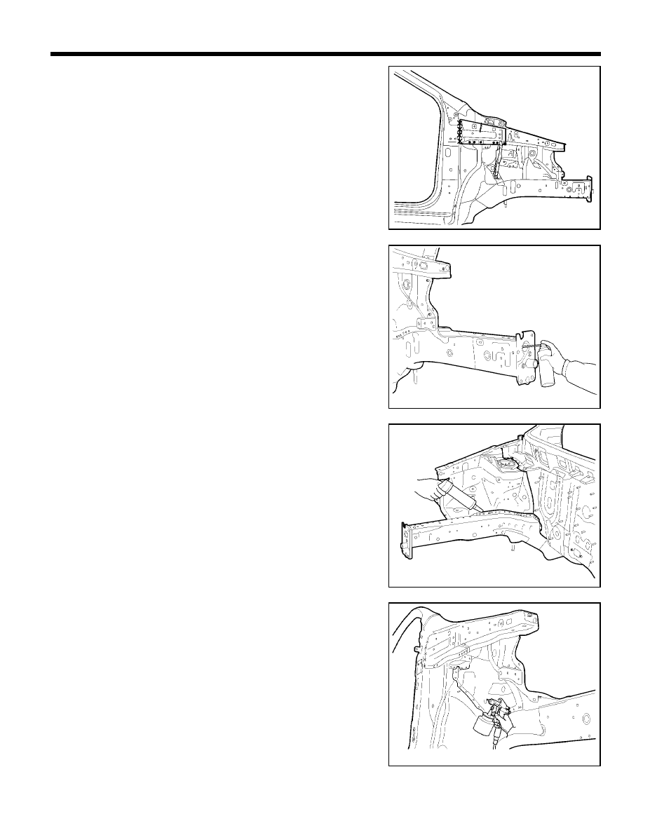
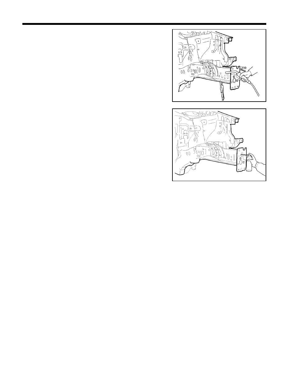
8.
Using a hammer and dolly, correct any flanges that become bent
or deformed when spotwelds are broken.
3.
Temporarily install new parts in place.
4.
Measure each measurement point (Refer to the BODY DIMEN-
SIONS) and corrcet the installation position.
INSTALLATION
1.
Drill 8 mm holes in the new fender apron and front side member
for MIG plug welding.
2.
Remove paint from both sides of all portions that are to be welded
such as peripheries of MIG plug weld holes.
PRO-0190
PRO-0200
PRO-0100
PRO-0180
81
BODY PANEL REPAIR PROCEDURE - Fender apron and front side member (Assembly)
5.
MIG plug weld all holes
6.
Clean MIG welds with a disc grinder.
NOTE
1.
Be careful not to grind welded portions too much.
2.
The internal parts will be stronger if the weld traces are
not ground.
7.
Before welding the cowl side upper outer panel, apply the two part
epoxy primer and anti-corrosion agent to the interior of the fender
apron panel.
PRO-0230
PRO-0070
PRO-0220
PRO-0250
82
BODY PANEL REPAIR PROCEDURE - Fender apron and front side member (Assembly)
8.
Install the cowl side upper outer panel in place.
9.
MIG plug weld all holes.
10. Clean and prepare all welds, remove all residue.
11. Apply the two part epoxy primer to the interior of the each panel.
12. Apply an anti-corrosion agent as required
(Refer to the CORROSION PROTECTION).
13. Prepare the exterior surfaces for priming using wax and grease
remover.
14. Apply metal conditioner and water rinse.
15. Apply conversion coating and water rinse.
16. Apply the two-part epoxy primer.
17. Apply the correct seam sealer to all joints carefully
(Refer to the BODY SEALING LOCATION).
18. Reprime over the seam sealer to complete the repair.
19. After completing body repairs, carefully apply under coating to
the front sidemember and fender apron (Refer to the CORRO-
SION PROTECTION).
20. In order to improve corrosion resistance, if necessary, apply an
under body anti-corrosion agent to the panel which is repaired or
replaced (Refer to the CORROSION PROTECTION).
PRO-0270
PRO-0290
PRO-0260
PRO-0280
83
FRONT SIDE MEMBER (PARTIAL)
BODY PANEL REPAIR PROCEDURE - Front side member (Partial)
L/H
z
z
z
z
z
MIG plug welding
MIG butt welding
z
z
z
z
z
MIG plug welding
MIG butt welding
R/H
WELDLING POINTS
PRO-0310
PRO-0330
PRO-0300
PRO-0320
70mm
2 0 m m
20mm
84
REMOVAL
NOTE
This procedure is to be used only for repair of minor damage to
the front side member and when it is impossible to straighten the
damaged side member. The following procedure illustrates a
repair for the front left side member.
The procedure may also be applied to the front right side-
member.
1.
Measure and mark the vertical cutlines on front side member inner
tooling hole center.
2.
Drill out all the spotwelds to separate battery tray leg bracket from
front side member.
NOTE
1.
When spotwelded portions are not apparent, remove
paint with a rotary wire brush.
2.
In order to perform cutting and separation of spotwelded
points use a spot weld cutter which is larger than the size
of the nugget to make a hole only in the panels to be
replaced.
BODY PANEL REPAIR PROCEDURE - Front side member (Partial)
PRO-0310
PRO-0360
PRO-0370
PRO-0300
85
BODY PANEL REPAIR PROCEDURE - Front side member (Partial)
3.
Cut through the front side member inner and outer at cutlines.
NOTE
Take care not to cut through front side member inner
reinforcement.
4.
Prepare all surfaces to be welded.
INSTALLATION
1.
Transcribe the front side member inner and outer cutline to the
new front side member, cut to length and chamfer butt end to
improve weld surface.
2.
Drill 8mm holes in new front side member for MIG plug welding.
3.
Fit and clamp the front side member inner and outer in place.
4.
MIG plug weld all holes and MIG butt weld all seams.
5.
Measure each measurement point (Refer to the BODY DIMEN-
SIONS) and correct the installation position.
PRO-0390
PRO-0400
PRO-0100
PRO-0380
86
BODY PANEL REPAIR PROCEDURE - Front side member (Partial)
6.
Clean and prepare all welds, remove all residue.
7.
Apply the two-part epoxy primer to the interior of the front side
member.
8.
Apply an anti-corrosion agent as required
(Refer to the CORROSION PROTECTION).
9.
Prepare the exterior surfaces for priming using wax and grease
remover.
10. Apply metal conditioner and water rinse.
11. Apply conversion coating and water rinse.
12. Apply the two-part epoxy primer.
13. Apply the correct seam sealer to all joints carefully
(Refer to the BODY SEALING LOCATIONS).
14. Reprime over the seam sealer to complete the repair.
PRO-0420
PRO-0430
87
FRONT PILLAR
BODY PANEL REPAIR PROCEDURE - Front pillar
z
z
z
z
z
MIG plug welding
MIG butt welding
xx MIG lap welding
WELDLING POINTS
Ô
Ô
Ô
Ô
Ô
A
Ô
Ô
Ô
Ô
Ô
C
PRO-0450
PRO-0480
PRO-0470
Ô
Ô
Ô
Ô
Ô
D
PRO-0481
Í
Í
Í
Í
Í
Ó
Ó
Ó
Ó
Ó
C
ÎÎÎÎÎ
A
Ô
Ô
Ô
Ô
Ô
B
PRO-0460
Î Î Î Î Î
D
B
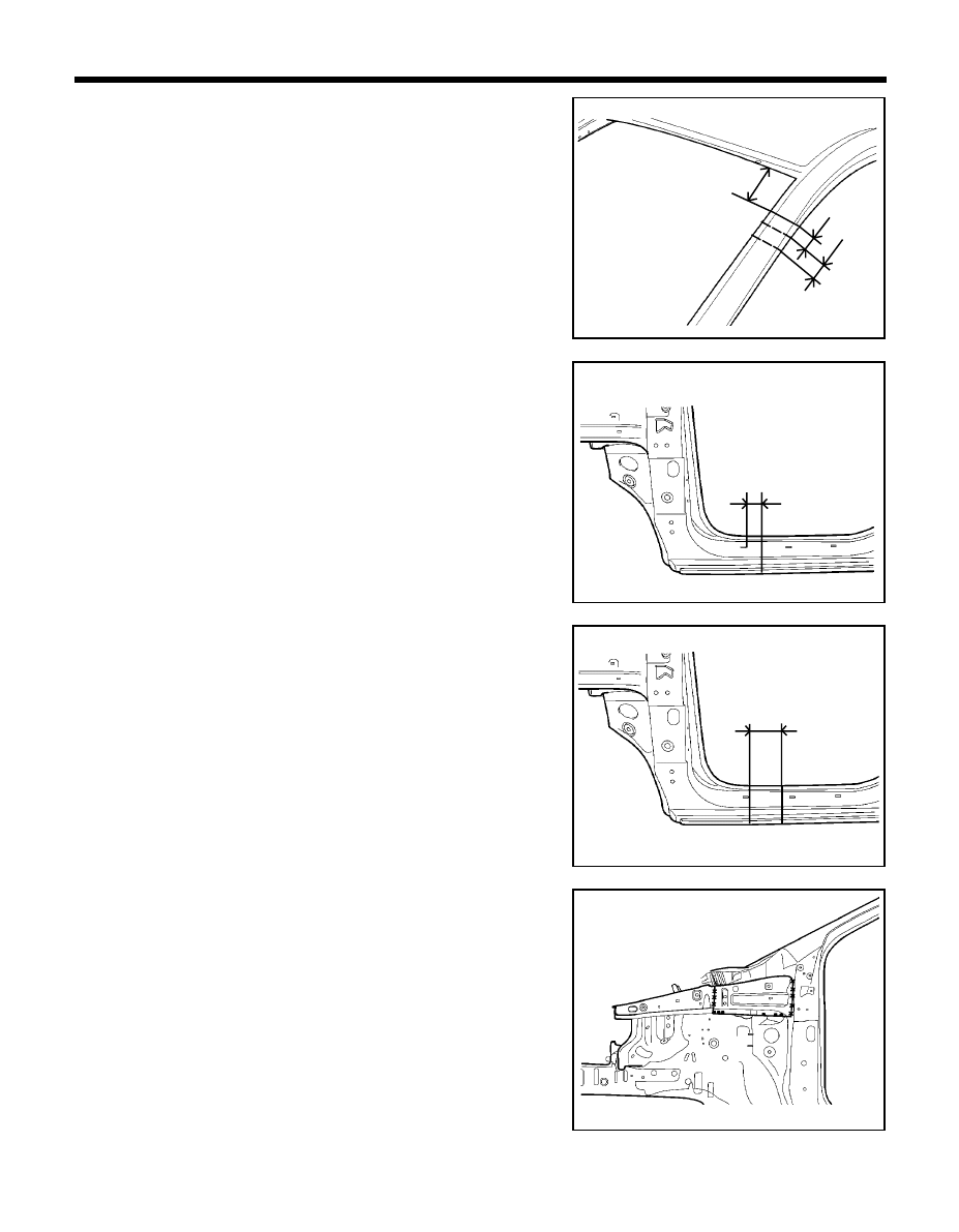
88
BODY PANEL REPAIR PROCEDURE - Front pillar
REMOVAL
1.
Measure and mark the each cutline on the front outer pillar at
150mm from the roof panel end line as indicated in the illustration.
2.
Measure and mark the cutline on front side sill outer panel as
shown in the illustration.
3.
Depending on the extend of damaged area, it may be possible to
determine the cutting range within indicated in the illustration.
4.
To remove the front pillar, grind away and drill out all welds
attaching the cowl side upper outer panel as shown in the
illustration.
NOTE
If it is possible that the cowl side upper outer panel is
reusable, be careful not to damage it while removing.
PRO-0510
PRO-0520
PRO-0500
30mm
PRO-0490
50mm
80mm
130mm
150mm
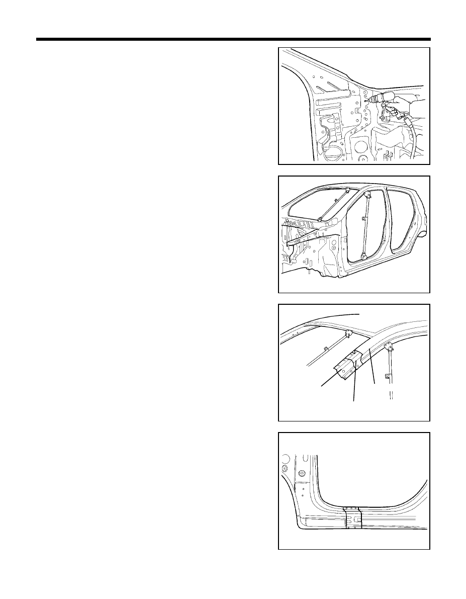
89
BODY PANEL REPAIR PROCEDURE - Front pillar
5.
Drill out all welds attaching the front pillar to dash and cowl top
outer, cowl inner lower panels.
6.
Remove spotwelds and lap welds attaching cowl crossmember
bar mounting upper bracket to remove front pillar.
7.
Before cutting front pillar, be sure to support roof panel.
8.
Cut the front pillar through each cutline, taking care not to damage
the other panel as illustration.
9.
Before cutting the front side sill outer panel, make a rough cut the
side sill outer panel only.
NOTE
When cutting the front side sill outer panel, be careful not to
cut side outer reinforcement.
PRO-0540
PRO-0550
PRO-0560
PRO-0530
Side outer reinforcement
Front pillar outer
panel
Side inner panel
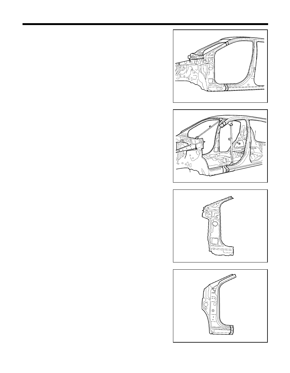
90
BODY PANEL REPAIR PROCEDURE - Front pillar
10. Cut the side outer reinforcement as shown in the illustration.
11. Cut the side outer reinforcement vertical cutline and remove the
front pillar.
12. Straighten all flanges as necessary, prepare all surfaces to be
welded.
INSTALLATION
1.
Transcribe the cutline to the new side inner panel, cut to length
and chamfer butt end to improve weld surface.
2.
Transcribe the cutline to the new side outer reinforcement and
new front pillar, adding 30mm overlap to end and cut to length.
3.
Drill 8mm holes along outer panel flanges in production location
for attachment to other panels.
PRO-0580
PRO-0590
PRO-0570
PRO-0600
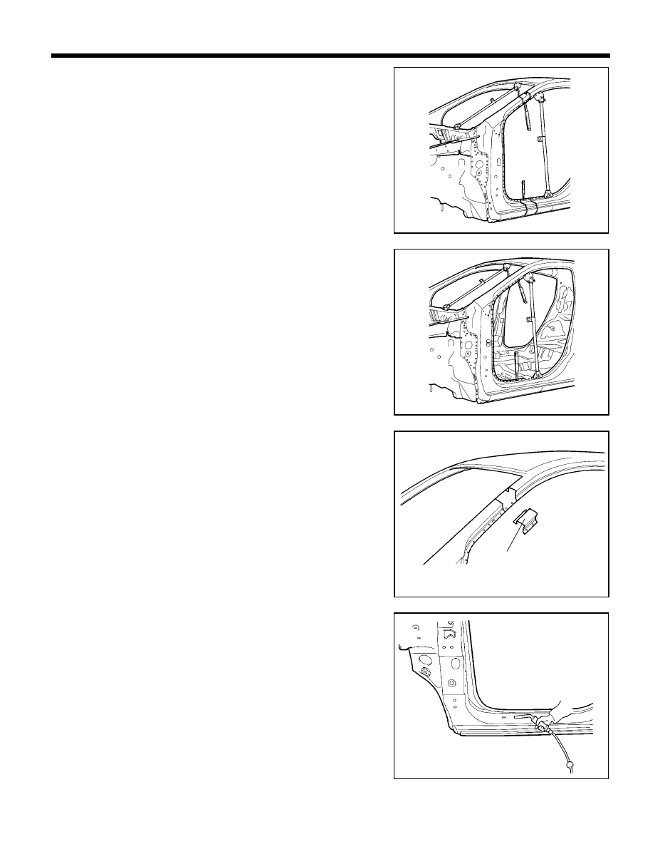
91
BODY PANEL REPAIR PROCEDURE - Front pillar
4.
Transcribe the cutline to the new side inner panel, adding 30mm
overlap to end and cut to length.
5.
Drill 8mm holes in the side inner panel for MIG plug welding.
6.
Fit and clamp the new side inner panel in place for welding.
7.
MIG plug weld all holes and MIG butt weld the seams.
8.
Temporarily install front pillar outer panel in place.
9.
Measure and each measurement point (Refer to the BODY
DIMENSIONS) and correct the installation position.
10. If necessary, make temporary welds, and then check to confirm
that the closing and fit for windshield glass, door and fender are
correct.
11. MIG butt weld front pillar outer panel and side outer reinforcement
seams.
12. Reattach the cut away front pillar outer panel section, then MIG
butt weld.
13. MIG plug weld all holes and MIG butt weld all seams in the side
outer panel.
14. Clean and prepare all welds, remove all residue.
15. Apply body filler to joints and sand as needed.
16. Apply the two-part epoxy primer to the interior of the front pillar.
PRO-0620
PRO-0630
PRO-0610
PRO-0640
Front pillar outer panel
section
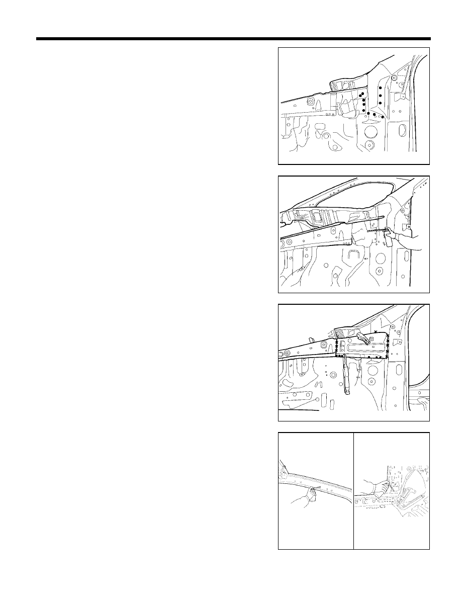
92
BODY PANEL REPAIR PROCEDURE - Front pillar
17. Clean all welds with a disc grinder.
NOTE
1.
Be careful not to grind welded portions too much.
2.
The internal parts will be stronger if the weld traces are
not ground.
18. Before welding the cowl side upper outer panel, apply the two part
epoxy primer and anti-corrosion agent to the interior of the fender
apron panel.
19. Install the cowl side upper outer panel in place.
20. MIG plug weld all holes.
21. Clean and prepare all welds, remove all residue.
22. Apply an anti-corrosion agent to the welded parts and inside of
front pillar (Refer to the CORROSION PROTECTION).
23. Prepare exterior surfaces for priming, using wax and grease
remover.
24. Apply metal conditioner and water rinse.
25. Apply conversion coating and water rinse.
26. Apply the two-part epoxy primer.
PRO-0460
PRO-0660
PRO-0670
PRO-0690
PRO-0680
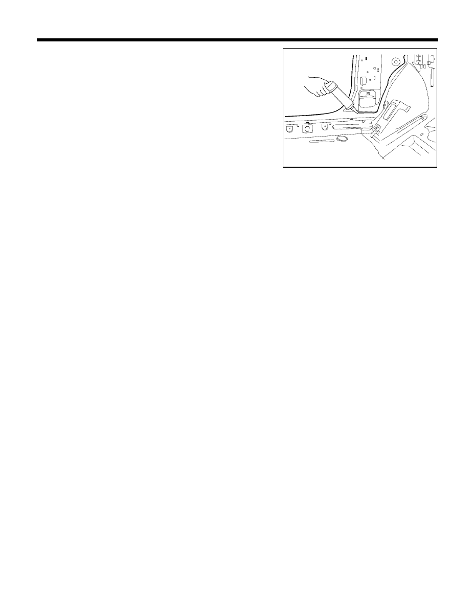
93
BODY PANEL REPAIR PROCEDURE - Front pillar
27. Apply the correct seam sealer to all joints carefully
(Refer to the BODY SEALING LOCATIONS).
28. Reprime over the seam sealer to complete the repair.
PRO-0700
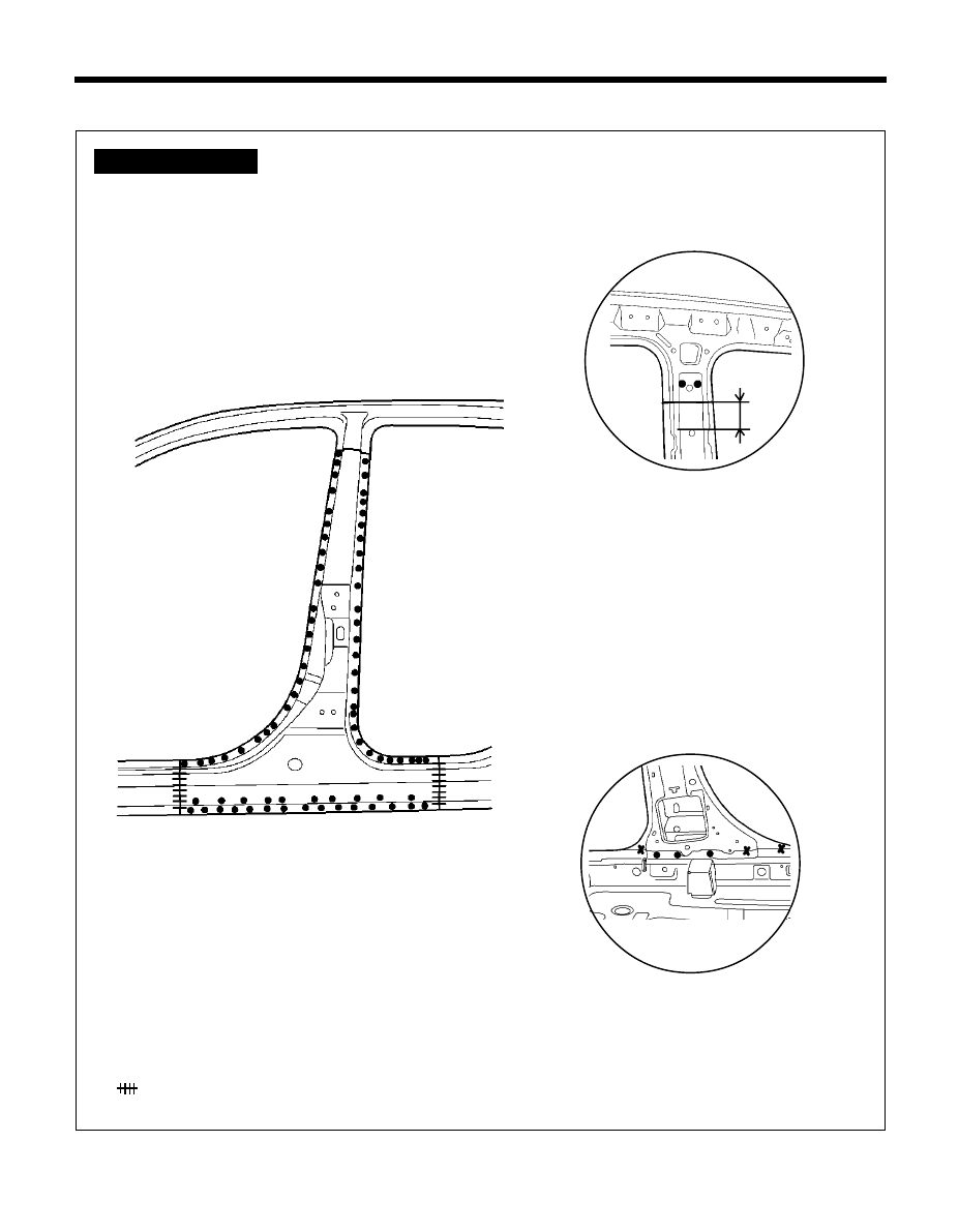
94
CENTER PILLAR
BODY PANEL REPAIR PROCEDURE - Center pillar
z
z
z
z
z MIG plug welding
MIG butt welding
WELDLING POINTS
PRO-0720
PRO-0730
PRO-0710
Ô
Ô
Ô
Ô
Ô
A
Ô
Ô
Ô
Ô
Ô
B
Ò
A
Ó
B
50mm
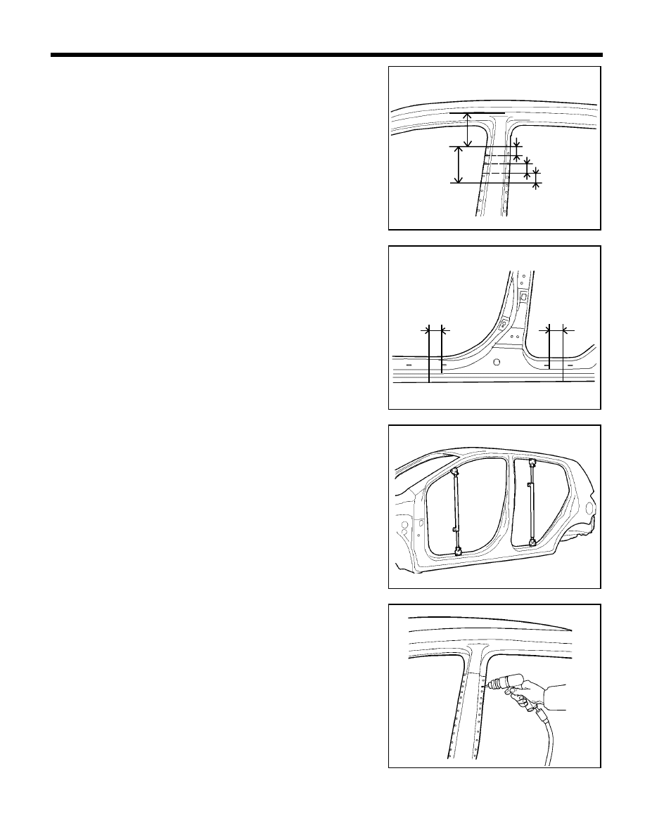
95
BODY PANEL REPAIR PROCEDURE - Center pillar
REMOVAL
1.
Measure and mark the horizontal cutline on center outer pillar as
indicated in the illustration.
2.
Measure and mark the vertical cutline on side sill outer panel
30mm from the front door step trim mounting hole.
3.
Before cutting center pillar, be sure to support roof panel.
4.
Drill out all spotwelds attaching the center outer pillar to the body
to remove center outer pillar.
PRO-0750
PRO-0740
PRO-0760
PRO-0770
30mm
90mm
150mm
120mm
30mm
30mm
30mm
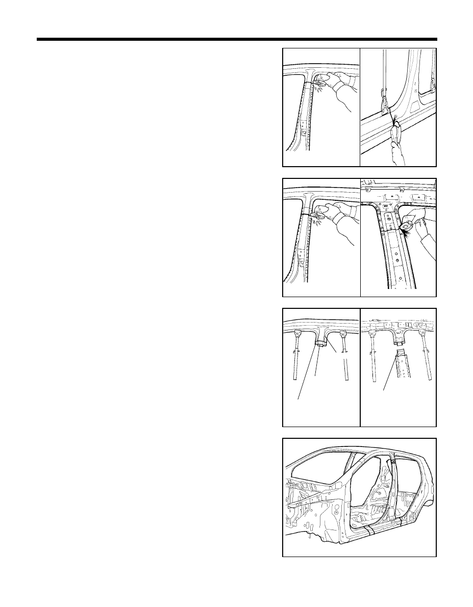
96
BODY PANEL REPAIR PROCEDURE - Center pillar
5.
Cut through center outer pillar and side sill outer panel at cutlines.
NOTE
When cutting side sill outer panel take care not to cut through
mating flanges or side outer reinforcement.
6.
After cutting side outer panel (center outer pillar & side sill), cut
the side outer reinforcement and center inner pillar.
7.
Remove the center pillar.
NOTE
When cutting center inner pillar, be careful not to cut front
seat belt mounting upper bracket.
8.
Determine if the side outer reinforcement is damaged and needs
to be replaced. If replacing is necessary, mark out the damaged
portion of the reinforcement. Cut at cutlines and remove damaged
portion.
9.
Straighten all flanges as necessary.
10. Prepare all surfaces to be welded.
PRO-0780
PRO-0820
PRO-0810
PRO-0830
PRO-0790
PRO-0795
PRO-0800
Center piller
outer upper
reinforcement
Front seat belt upper
mounting bracket
Side outer
reinforcement
Side outer
panel
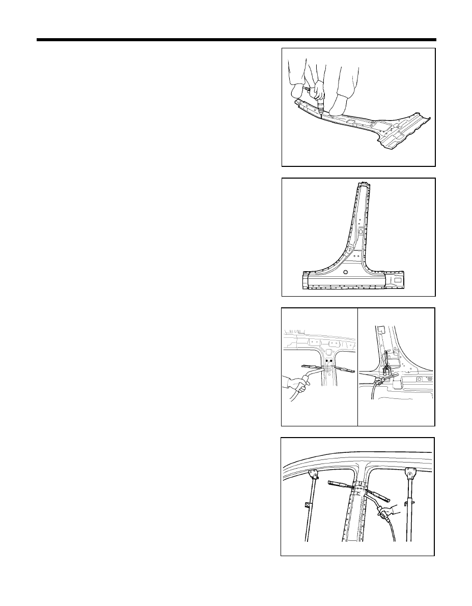
97
BODY PANEL REPAIR PROCEDURE - Center pillar
INSTALLATION
1. In order to install center inner pillar drill out all spotwelds attaching
the roof side inner rail to center inner pillar to separate them.
2. Transcribe the center outer pillar cutlines to the new center outer
pillar, adding 30mm overlap at center lower pillar ends.
3. Cut and chamfer butt end to improve weld surface.
4. Drill 8mm holes in overlap area and along outer panel flanges.
5. MIG butt weld all seams in center inner pillar and side outer
reinforcement as shown in the illustration.
PRO-0850
PRO-0880
PRO-0840
PRO-0860
PRO-0870
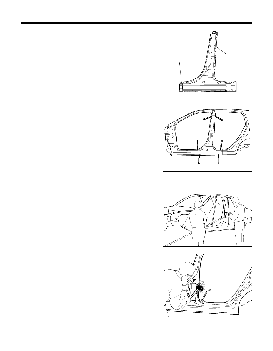
98
BODY PANEL REPAIR PROCEDURE - Center pillar
6.
Transcribe the cutline dimensions to the new side outer reinforce-
ment, adding 30mm overlap to each end and cut to length.
7.
Drill 8mm holes in overlap areas on each end of new side outer
reinforcement and clamp the new side outer reinforcement in
place.
8.
MIG plug weld all holes and MIG butt weld seams.
NOTE
The reinforcement will be stronger if the weld traces are not
ground.
9.
Temporarily install new center outer panel in place.
10. Screw center pillar in place.
11. Measure and each measurement point (Refer to the BODY
DIMENSIONS) and correct the installation position.
12. Check the fit of the front and rear doors.
13. Reinstall center outer pillar and screw in place.
14. MIG plug weld all holes and MIG butt weld all seams.
15. Clean and prepare all welds, and remove all residue.
16. Apply body filler to the outer center pillar seam. Sand and finish.
17. Apply the two-part epoxy primer to the interior of the center pillar.
18. Apply an anti-corrosion agent to the welded parts and interior of
the center pillar (Refer to the CORROSION PROTECTION).
PRO-0850
PRO-0900
PRO-0910
PRO-0920
Side outer
reinforcement
Center pillar
outer panel
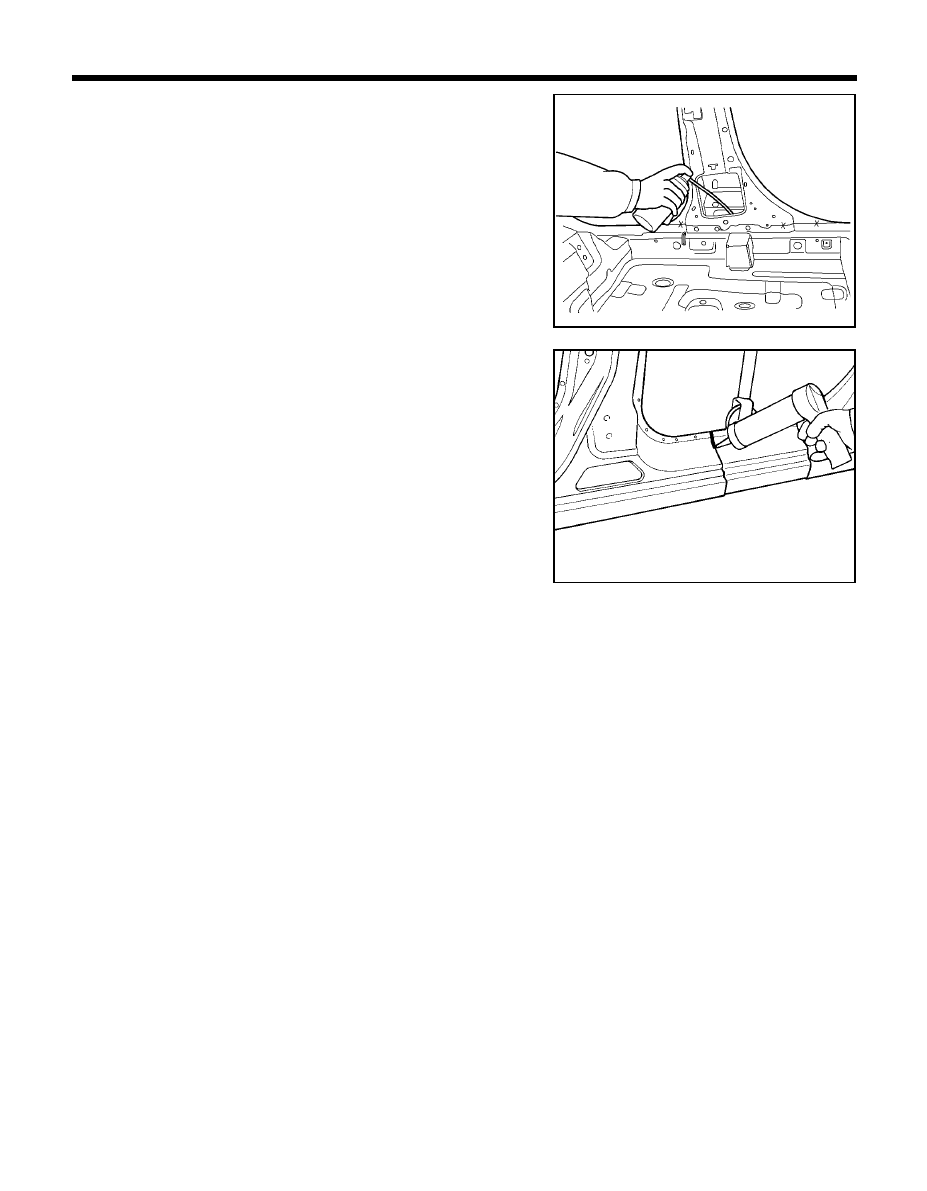
99
BODY PANEL REPAIR PROCEDURE - Center pillar
19. Prepare exterior surfaces for priming, using wax and grease
remover.
20. Apply metal conditioner and water rinse.
21. Apply conversion coating and water rinse.
22. Apply the two-part epoxy primer.
23. Apply the correct seam sealer to all joints carefully (Refer to the
BODY SEALING LOCATIONS).
PRO-0940
PRO-0930
24. Reprime over the seam sealer to complete the repair.
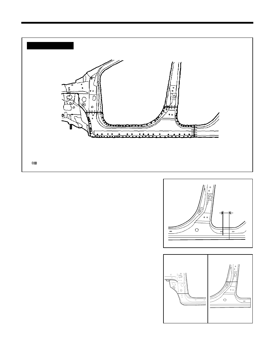
100
BODY PANEL REPAIR PROCEDURE - Side sill (Assembly)
SIDE SILL (ASSEMBLY)
REMOVAL
1.
Measure and mark vertical cutline from the rear door step trim
mounting hole on the rear side sill inner panel.
2.
At the front and center pillar, measure and mark horizontal
cutlines from the door hinge mounting hole on the side outer panel
as shown in the illustration.
z
z
z
z
z MIG plug welding
MIG butt welding
WELDLING POINTS
PRO-0971
PRO-0970
PRO-0950
PRO-0960
90mm
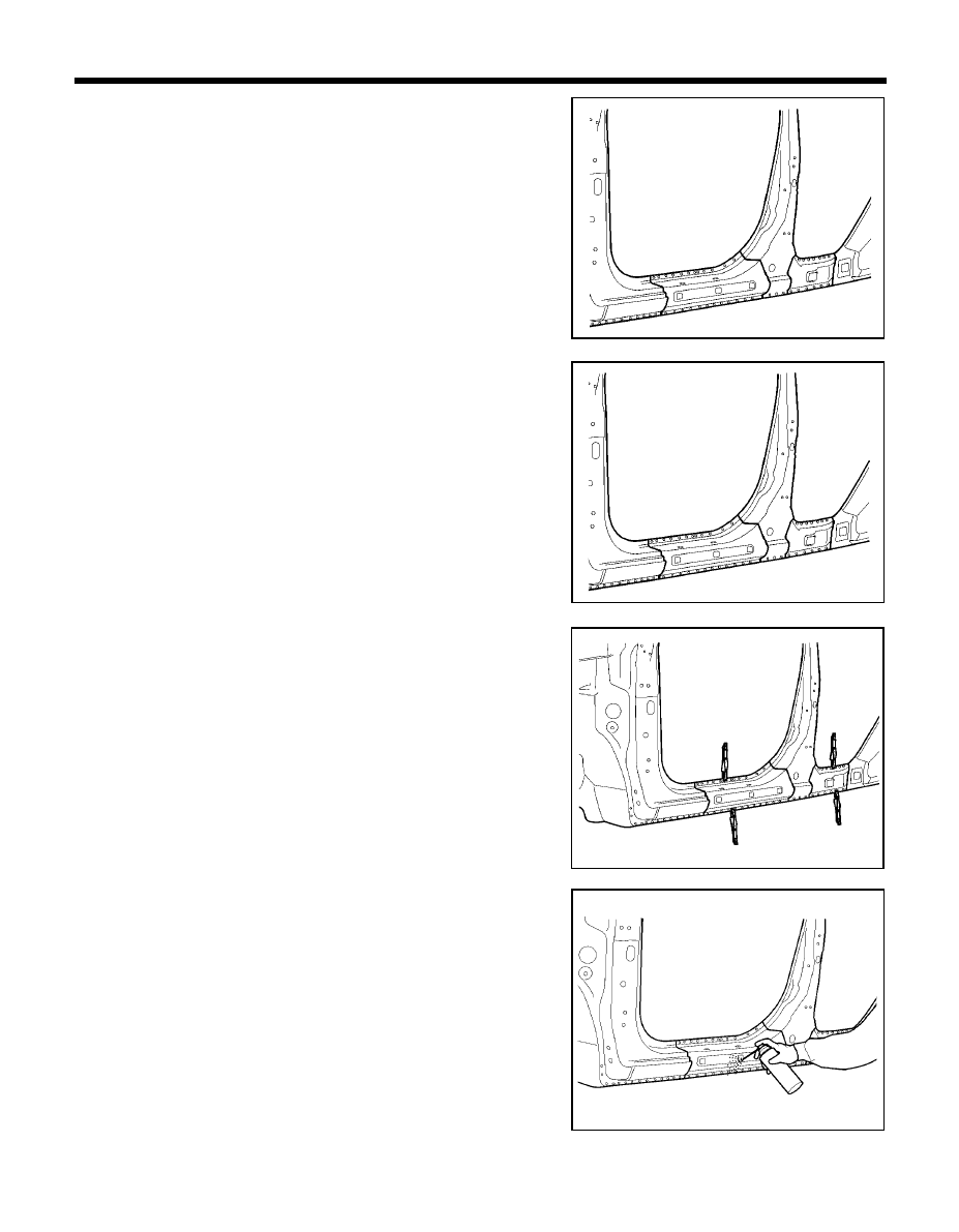
101
BODY PANEL REPAIR PROCEDURE - Side sill (Assembly)
3.
Cut the side sill outer panel along cutlines. Be careful not to cut
mating flanges.
4.
Drill out all spotwelds, attaching the side sill outer panel to side
outer reinforcement.
5.
Remove the side sill outer panel.
6.
Determine if the side outer reinforcement is damaged and needs
to be replaced, measure cutline on reinforcement as shown in the
illustration.
7.
Cut side sill outer reinforcement along the cutline.
8.
Drill out spotwelds attaching the side outer reinforcement to the
body and remove side outer reinforcement.
9.
Prepare all surfaces to be welded.
INSTALLATION
1.
Transcribe cutline dimension to side sill outer panel, adding
30mm overlap to rear end and cut to length.
2.
Drill 8mm holes in overlap area on rear end and along front flange.
3.
Fit and clamp the side sill outer reinforcement in place.
4.
MIG plug weld all holes and MIG butt weld seams.
5.
Before welding the side sill outer panel, apply the two-part epoxy
primer and anti-corrosion agent to the welded parts.
NOTE
The reinforcement will be stronger if the weld traces are not
ground.
PRO-1020
PRO-1020
PRO-1030
PRO-1040
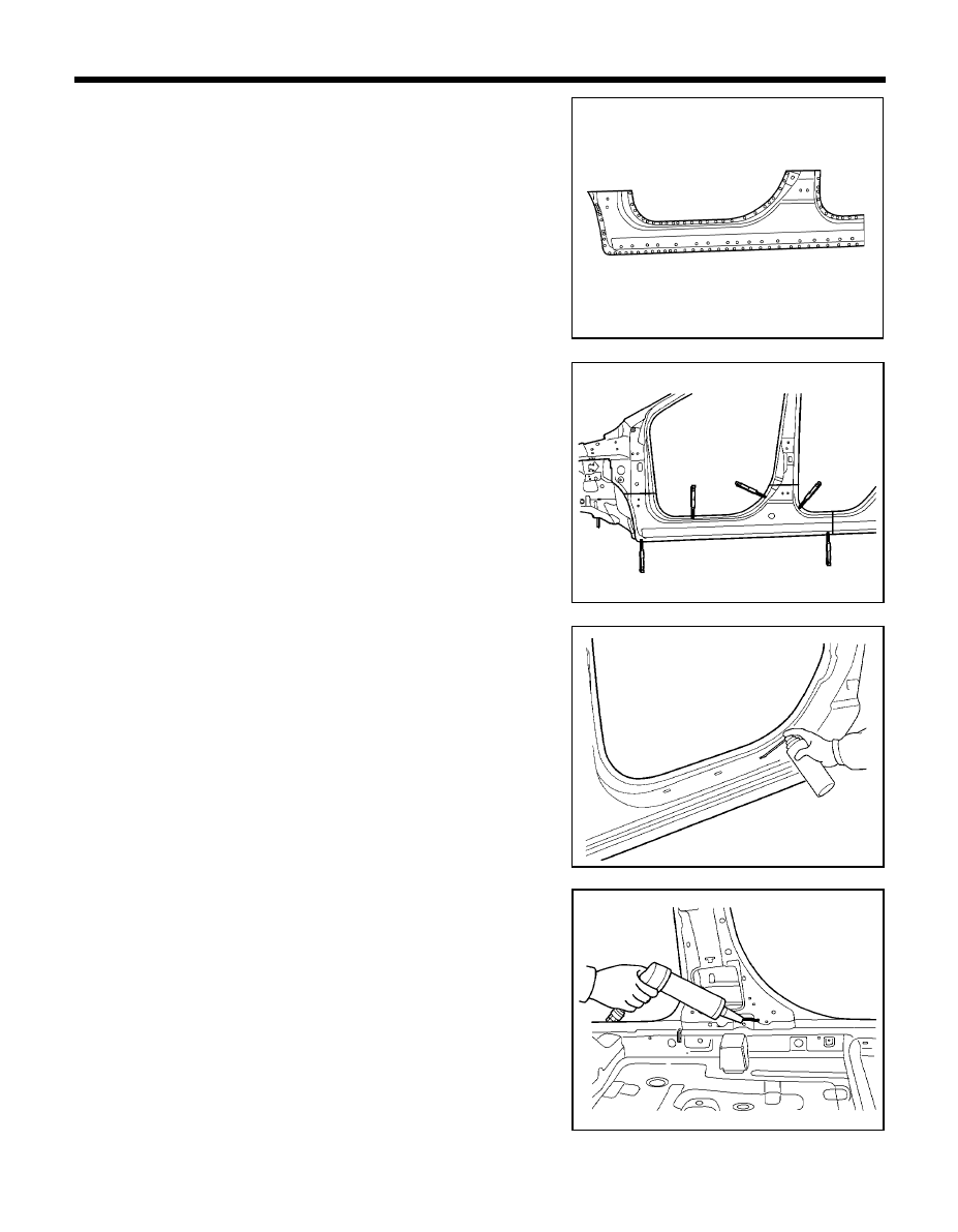
102
BODY PANEL REPAIR PROCEDURE - Side sill (Assembly)
7.
Crimp flanges on the remaining portion of the side sill outer panel
at all joint for overlap.
8.
Fit and clamp the side sill outer panel in place.
9.
MIG plug weld all holes and MIG butt weld seams.
10. Clean and prepare all welds and remove all residue.
11. Apply body filler to the side sill outer seams.
12. Apply the two-part epoxy primer to the interior of the side sill.
13. Apply an anti-corrosion agent to welded parts and interior of the
side sill (Refer to the CORROSION PROTECTION).
14. Prepare the exterior surfaces for priming, using wax and grease
remover.
15. Apply metal conditioner and water rinse.
16. Apply conversion coating and water rinse.
17. Apply the two-part epoxy primer.
6.
Using service panel for replacement of side sill outer panel, drill
8mm holes in overlap areas and along upper and lower flanges.
18. Apply the correct seam sealer to all joints (Refer to the BODY
SEALING LOCATIONS).
19. Reprime over the seam sealer.
PRO-1050
PRO-1060
PRO-1180
PRO-1080
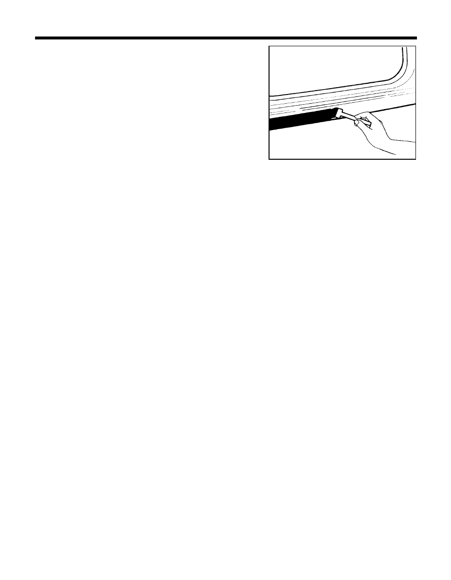
103
BODY PANEL REPAIR PROCEDURE - Side sill (Assembly)
20. Apply the anti-corrosion primer to the side sill outer panel to
complete the repair (Refer to the CORROSION PROTECTION).
PRO-1090
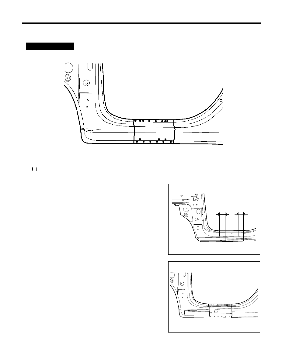
104
SIDE SILL (PARTIAL)
REMOVAL
1.
Depending on the extent of damage, mark out the damaged
portion of the side sill.
2.
Drill out the spotwelds in upper and lower flanges of side sill
between cutlines to remove side sill outer panel and cut the
damaged portion of the side sill at the cutlines.
BODY PANEL REPAIR PROCEDURE - Side sill (partial)
z
z
z
z
z MIG plug welding
MIG butt welding
WELDLING POINTS
PRO-1100
PRO-0500
PRO-1120
30mm
30mm
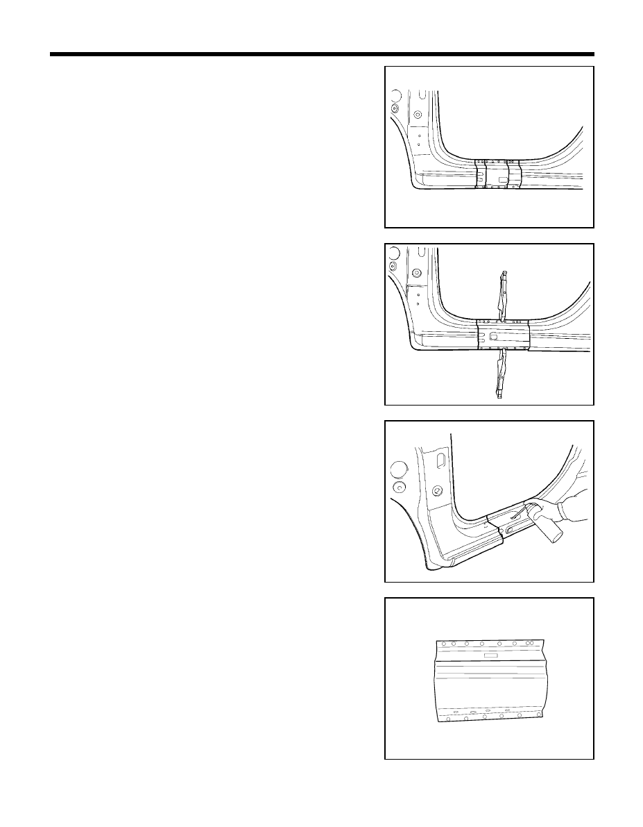
105
3.
Determine if the side outer reinforcement is damaged and needs
to be replaced. If replacing is necessary, mark out the damaged
portion of the side outer reinforcement. Cut at cutlines and
remove the damaged portion.
4.
Prepare all surfaces to be welded.
INSTALLATION
1.
Transcribe the cutline to the new front side outer reinforcement,
adding 30 mm overlap to each end and cut to length.
2.
Drill 8 mm holes in overlap areas on each end and upper flange of
new side outer reinforcement and clamp the new side outer
reinforcement in place.
3.
MIG plug weld all holes and MIG butt weld all seams.
NOTE
The reinforcement will be stronger if the weld traces are not
ground.
4.
Before welding the side sill outer panel, apply the two part epoxy
primer and anti-corrosion agent to the welded parts.
BODY PANEL REPAIR PROCEDURE - Side sill (partial)
5.
Transcribe the side sill outer panel cutline to the new side sill,
adding 30 mm overlap to each end, cut and chamfer butt end to
improve weld surface.
6.
Drill 8 mm holes in overlap areas on each end and along upper and
lower flanges of the new side sill outer panel for MIG plug welding.
PRO-1130
PRO-1140
PRO-1150
PRO-1160
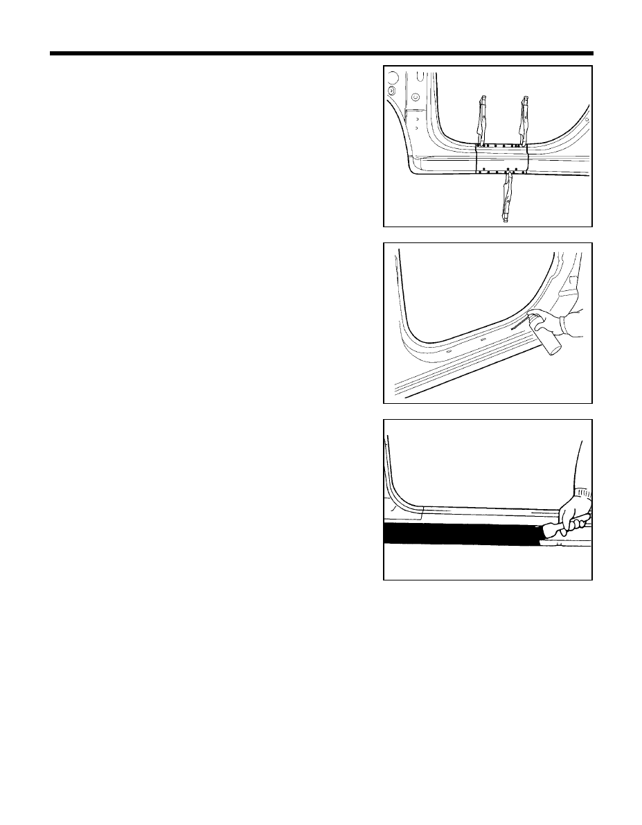
106
7.
Fit and clamp the side sill in place.
8.
MIG plug weld all holes and MIG butt weld seams.
9.
Clean and prepare all welds, remove all residue.
10. Apply body filler to the side sill outer seams.
11. Apply the two-part epoxy primer to the interior of the side sill.
12. Apply an anti-corrosion agent to the welded parts and interior of
the side sill (Refer to the CORROSION PROTECTION).
13. Prepare the exterior surfaces for priming, using wax and grease
remover.
14. Apply metal conditioner and water rinse.
15. Apply conversion coating and water rinse.
16. Apply the two-part epoxy primer.
17. Apply the anti-corrosion primer to the side sill outer panel to
complete the repair (Refer to the CORROSION PROTECTION).
BODY PANEL REPAIR PROCEDURE - Side sill (partial)
PRO-1170
PRO-1180
PRO-1190
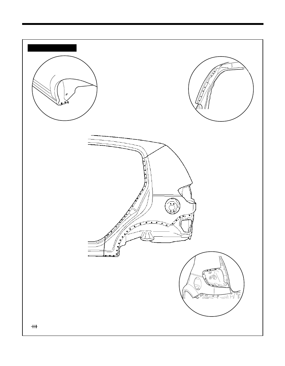
107
BODY PANEL REPAIR PROCEDURE - Quarter panel
QUARTER PANEL
z
z
z
z
z MIG plug welding
MIG butt welding
WELDLING POINTS
PRO-1220
Ô
A
PRO-1200
PRO-1201
Ô
B
Ô
C
PRO-1202
Í
Í
C
A
B
Í
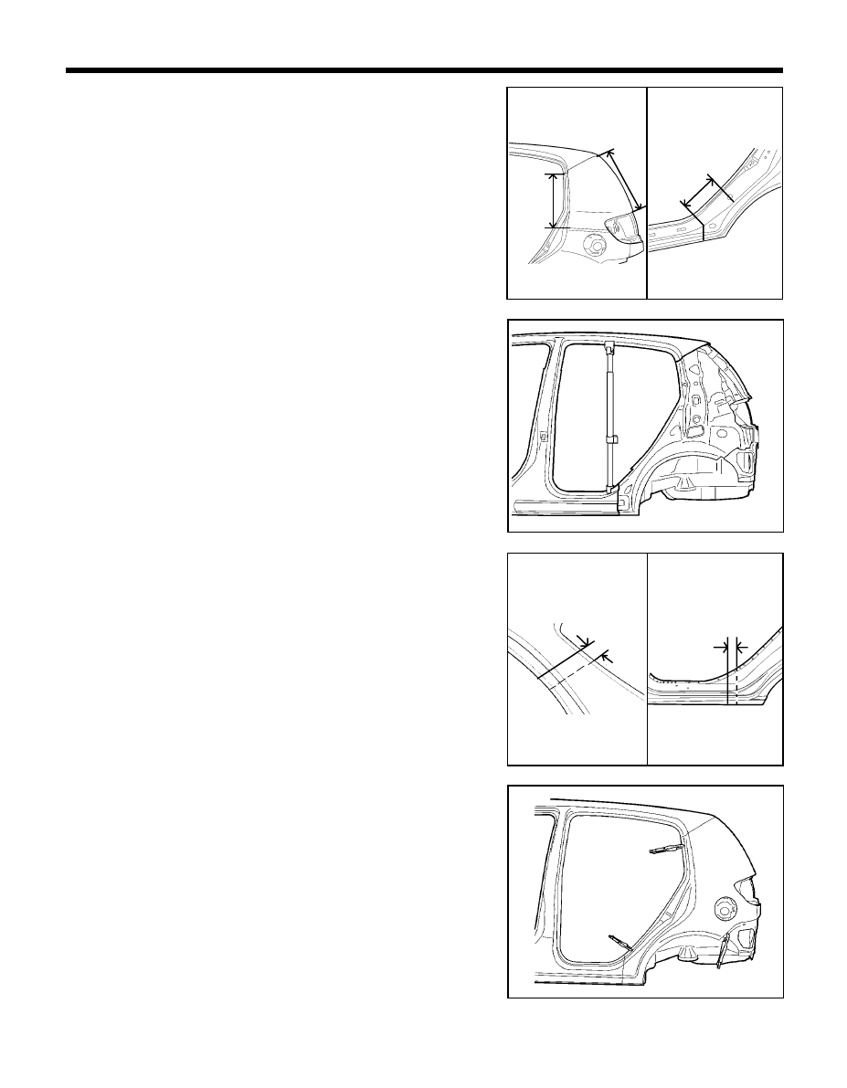
108
2.
Drill out all attaching spotwelds on the quarter outer panel,
including the seam around the door lip opening.
3.
Cut the quarter outer panel at cutlines and remove the quarter
outer panel as illustration.
NOTE
When cutting the quarter outer panel, be careful not to cut
quarter inner panel.
4.
Prepare all surfaces to be welded.
INSTALLATION
1.
Transcribe the cutline to the new quarter outer panel, adding 30
mm for overlap at the old joint.
2.
Drill 8 mm holes in overlap areas and along upper and lower
flanges of the new quarter outer panel for MIG plug welding.
3.
Fit and clamp the quarter outer panel in place.
4.
MIG plug weld all holes and MIG butt weld seams. At the wheel
well the edge must be crimped over the wheel housing.
This joint may be welded after crimping or applying a bead of
adhesive which may be applied to the joint before or after
crimping.
5.
Clean and prepare all welds, remove all residue.
REMOVAL
1.
Depending on the extent of damage, measure and mark cutlines
on the quarter outer panel as indicated in the illustration.
BODY PANEL REPAIR PROCEDURE - Quarter panel
PRO-1250
PRO-1260
PRO-1250
PRO-1260
PRO-1300
PRO-1270
30mm
420mm
30mm
200mm
480mm
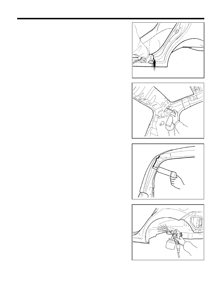
109
BODY PANEL REPAIR PROCEDURE - Quarter panel
7.
Apply an anti-corrosion agent to the welded parts and interior of
the quarter outer panel (Refer to the CORROSION PROTECTION).
8.
Prepare exterior surfaces for priming, using wax and grease
remover.
9.
Apply metal conditioner and water rinse.
10. Apply conversion coating and water rinse.
11. Apply the two-part epoxy primer.
12. Apply the correct seam sealers to all joints.
13. Reprime over the seam sealer to complete the repair.
14. In order to improve corrosion resistance, if necessary, apply an
under body anti-corrosion agent to the wheel well (Refer to the
CORROSION PROTECTION).
6.
Apply body filler to the welded seam. Sand and finish.
Apply the two-part epoxy primer to the interior of the quarter outer
panel.
PRO-1310
PRO-1330
PRO-1340
PRO-1320
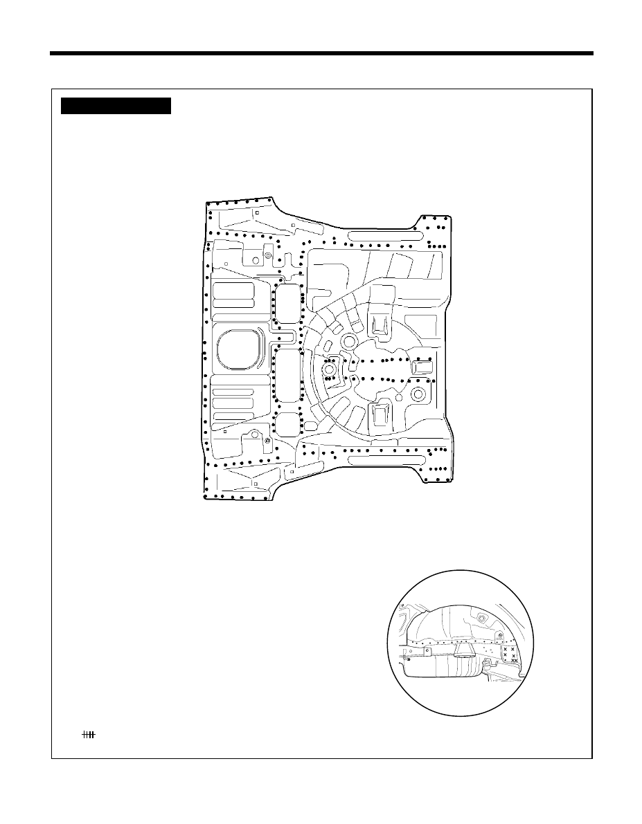
110
BODY PANEL REPAIR PROCEDURE - Rear floor
z
z
z
z
z MIG plug welding
MIG butt welding
REAR FLOOR
WELDLING POINTS
PRO-1520
PRO-1503
Ô
A
A
Ô
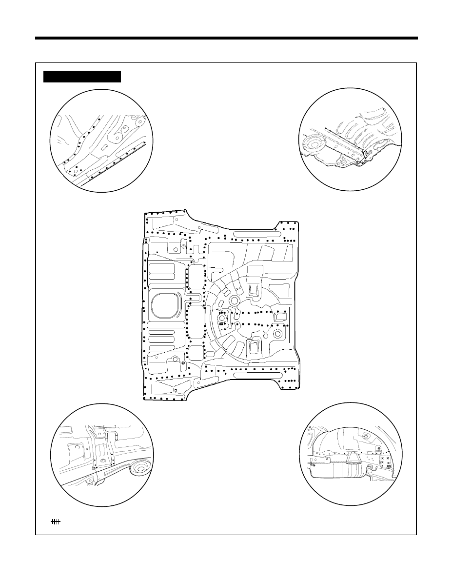
111
REAR SIDE MEMBER (ASSEMBLY)
BODY PANEL REPAIR PROCEDURE - Rear side member (assembly)
WELDLING POINTS
z
z
z
z
z MIG plug welding
MIG butt welding
PRO-1502
Ô
A
PRO-1500
Ô
B
Ô
C
Ô
D
PRO-1503
PRO-1520
PRO-1501
Ô
A
B
Ô
D
C
Ô
Ô
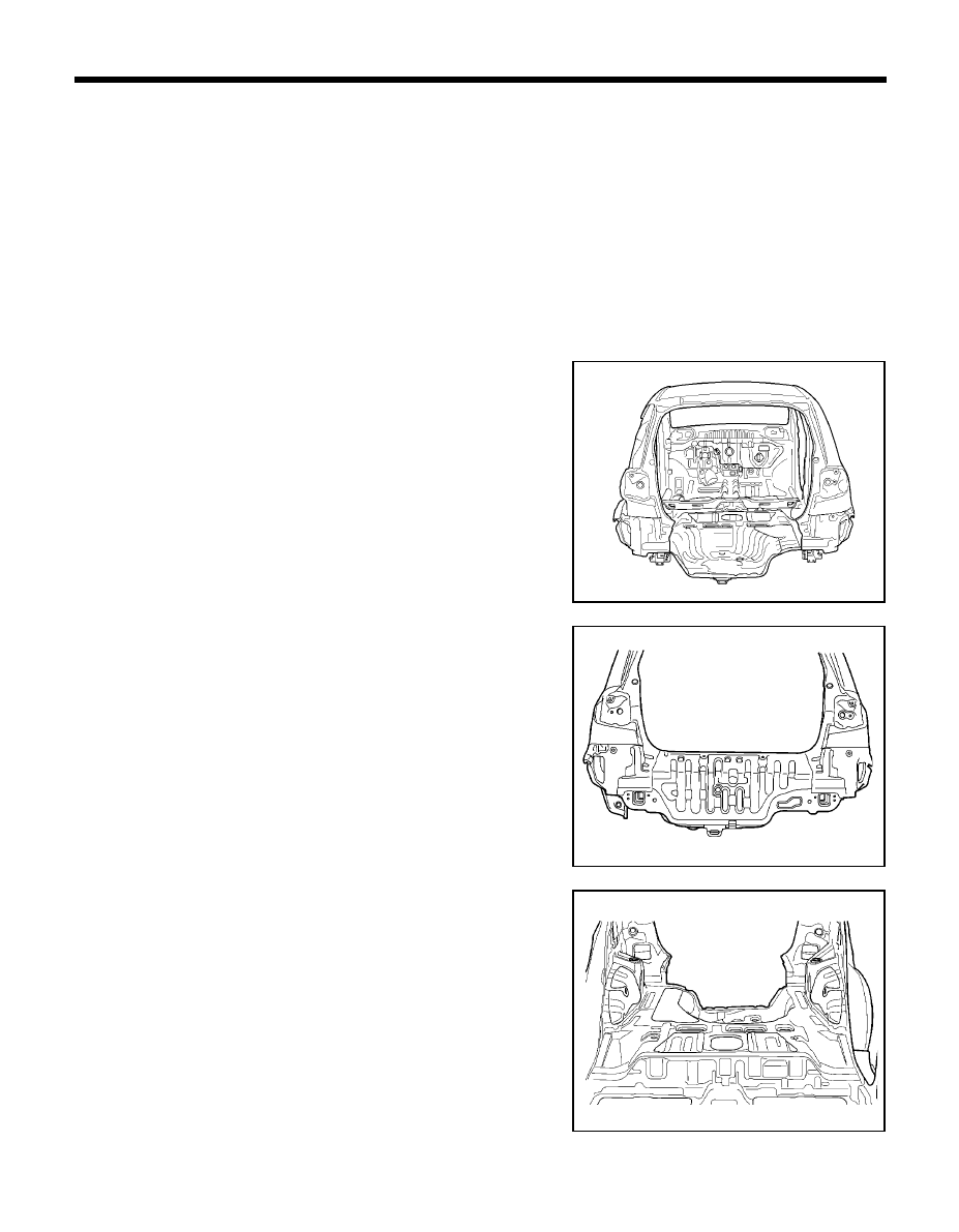
112
NOTE
Because the rear side members are desigened to absorb energy
during a rear collision, care must be taken when deciding to use this
repair method. This repair is recommended only for moderate damage
to vehicle, where distortions do not extend forward of the trunk region.
If the damage is more severe, then the entire side member assembly
should be replaced at factory seams without employing this sectioning
procedure.
Refer to the body dimension chart and measure the vehicle to
determine straigthening and alignment requirements. The body must
be returned to its original dimension before beginning the repair
procedure.
BODY PANEL REPAIR PROCEDURE - Rear floor and rear side member (assembly)
REMOVAL
1.
Drill out all the spotwelds attaching the rear floor panel to the
wheel housings and rear side members.
2.
Remove the rear floor panel
3.
Remove the back panel by drilling out all attaching spotwelds.
PRO-1550
PRO-1560
PRO-1570
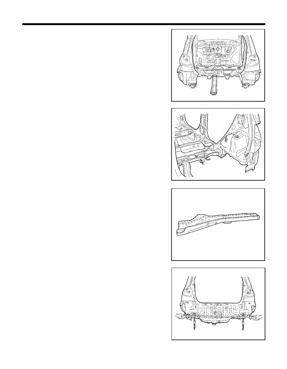
113
BODY PANEL REPAIR PROCEDURE - Rear floor and rear side member (assembly)
INSTALLATION
1.
Transcribe the cutline to the new rear side members. Drill out the
spotwelds attaching the inner reinforcements.
Remove remaining portions of side members.
2.
Temporarily fit and clamp the rear side members in place.
NOTE
When installing the rear floor side member, temporarily
install the back panel to measure each measurement point.
3.
Measure each measurement point (Refer to BODY DIMENSIONS)
and correct the installation position.
4.
If necessary, make temporarily welds, and then check to confirm
that the fit of rear floor panel is correct.
PRO-1580
PRO-1590
PRO-1600
PRO-1610
4.
Remove the rear floor panel and rear side member from the rear
body.
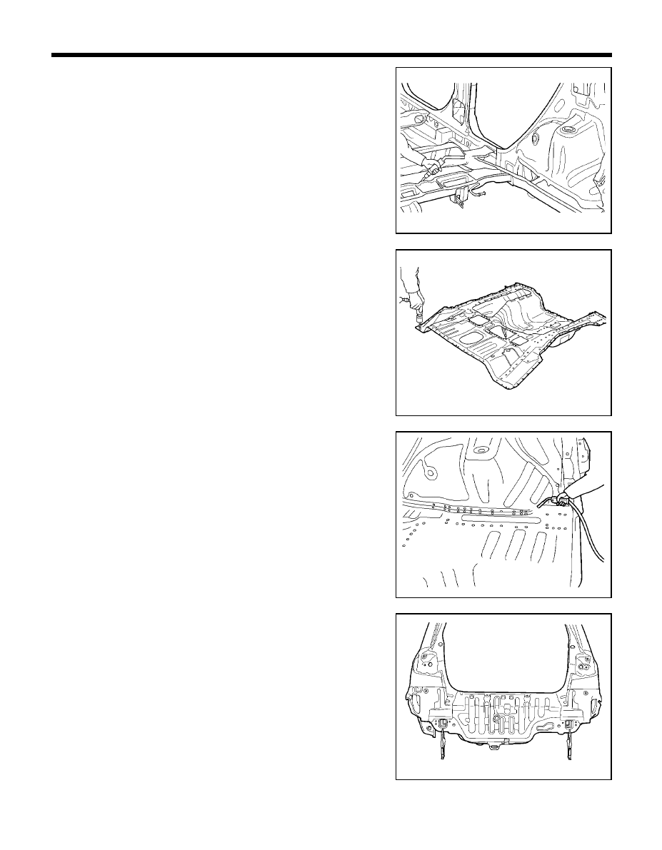
114
BODY PANEL REPAIR PROCEDURE - Rear floor and rear side member (assembly)
5.
MIG plug weld the rear side members and MIG butt weld seams.
6.
Prepare the welds and surfaces to which the rear floor will attach.
7.
Transcribe the cutline to the new rear floor panel, adding 30mm
for overlap at the old joint.
8.
Drill 8mm holes in overlap area and production locations of the
new rear floor panel for MIG plug welding.
9.
Fit and clamp the rear floor panel and attach the rear floor panel
to the rear side members and other panels.
10. MIG plug weld all holes and MIG butt weld the seams.
11. Clean all welded surfaces.
12. Drill 8 mm holes on the flange attaching the back panel to the rear
floor and side member ends.
13. Fit and clamp the back panel in place.
14. MIG plug weld the back panel.
15. Clean and prepare all welds, remove all residue.
16. Apply the two-part epoxy primer to the interior of the rear side
members.
PRO-1630
PRO-1640
PRO-1650
PRO-1620
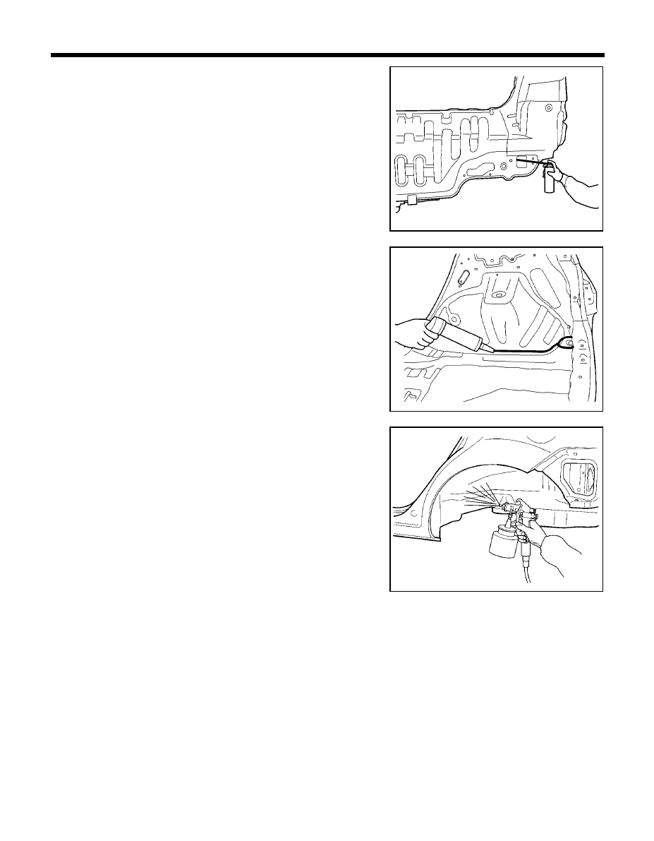
115
BODY PANEL REPAIR PROCEDURE - Rear floor and rear side member (assembly)
17. Apply an anti-corrosion to the interior of the rear side members
(Refer to the CORROSION PROTECTION).
18. Prepare exterior surfaces for priming, using wax and grease
remover.
19. Apply metal conditioner and water rinse.
20. Apply the two-part epoxy primer.
21. Apply the correct seam sealer to all joints (Refer to the BODY
SEALING LOCATIONS).
22. Reprime over the seam sealer to complete the repair.
23. After completing body repairs, carefully apply under coating to
the under body (Refer to the CORROSION PROTECTION).
24. In order to improve corrosion resistance, if necessary, apply an
under body anti-corrosion agent to the panel which is repaired or
replaced (Refer to the CORROSION PROTECTION).
PRO-1340
PRO-1660
PRO-1670
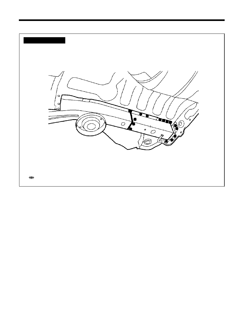
116
REMOVAL
NOTE
Because the rear side members are designed to absorb energy during
a rear collision, care must be used when deciding to use this repair
method. This repair is recommended only for moderate damage to the
vehicle, where distortions do not extend forward of the trunk region.
If the damage is more severe, then the entire side member assembly
should be replaced at the factory seams without employing this
sectioning procedure.
The following procedure applys when only one rear side member
needs to be replaced. If both side members are damaged and need to
be replaced, then the procedure of Rear Side members And Rear Floor
Section should be followed.
Refer to the body dimension charts and measure the vehicle to
determine straightening and alignment requirements. The body must
be returned to its original dimensions before beginning the
repair procedure.
REAR SIDE MEMBER (PARTIAL)
BODY PANEL REPAIR PROCEDURE - Rear side member (Partial)
z
z
z
z
z MIG plug welding
MIG butt welding
WELDLING POINTS
PRO-1690
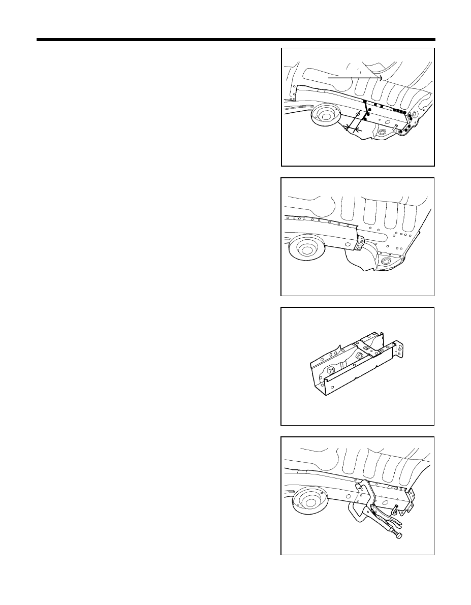
117
BODY PANEL REPAIR PROCEDURE - Rear side member (Partial)
1.
Depending on the extent of damage, if the right side member is
to be replaced it should be measured and marked 30mm from the
rear floor side member tooling hole center.
NOTE
The flowing procedure illustrates a repair for the right rear
side member. The procedure may also be applied the left rear
side member.
2.
Cut through rear side member at cutline being careful not to cut
rear side member reinforcement.
3.
Remove the rear floor side member by drilling out all attaching
spotwelds.
4.
Prepare all surfaces to be welded.
INSTALLATION
1.
Transcribe the cutline to the new rear side member. Cut at line and
drill out the spotwelds attaching the inner reinforcement and
separate it.
2.
Fit and clamp the new rear side member in place for welding.
Measure to ensure dimensions are accurate as given in the body
dimension charts.
3.
MIG plug weld at the holes and MIG butt weld the seam in the side
member.
4.
Clean and prepare all surfaces to be welded and remove all
residue.
5.
Apply the two-part epoxy primer to the interior of the rear side
member.
PRO-1690
PRO-1710
PRO-1720
PRO-1730
30mm
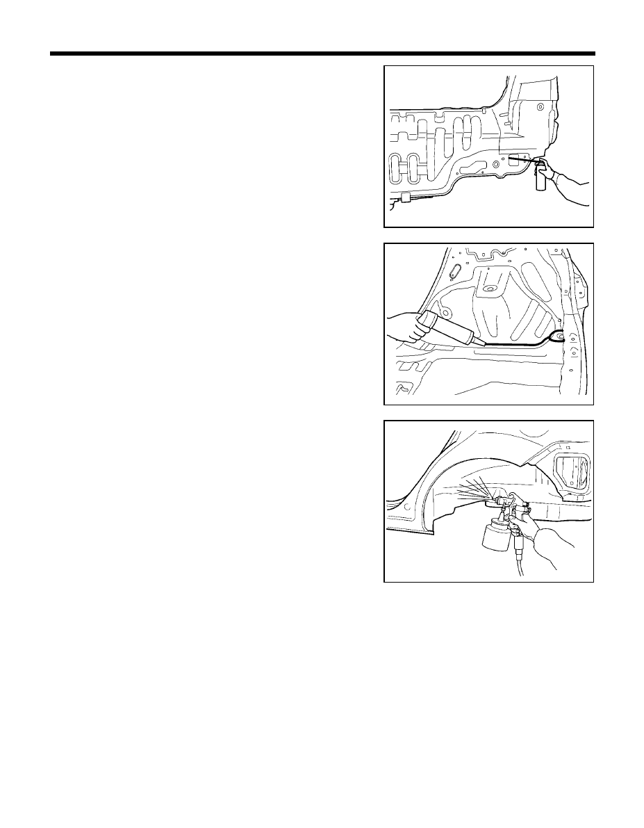
118
13. After completing body repairs, carefully apply under coating to
the under body (Refer to the CORROSION PROTECTION).
14. In order to improve corrosion resistance, if necessary, apply an
under body anti-corrosion agent to the panel which is repaired or
replaced (Refer to the CORROSION PROTECTION).
BODY PANEL REPAIR PROCEDURE - Rear side member (Partial)
6.
Apply an anti-corrosion to the interior of the rear side member
(Refer to the CORROSION PROTECTION).
7.
Prepare exterior surfaces for priming, using wax and grease
remover.
8.
Apply metal conditioner and water rinse.
9.
Apply conversion coating and water rinse.
10. Apply the two-part epoxy primer.
11. Apply the correct seam sealer to all joints (Refer to the BODY
SEALING LOCATIONS).
12. Reprime over the seam sealer to complete the repair.
PRO-1660
PRO-1340
PRO-1670
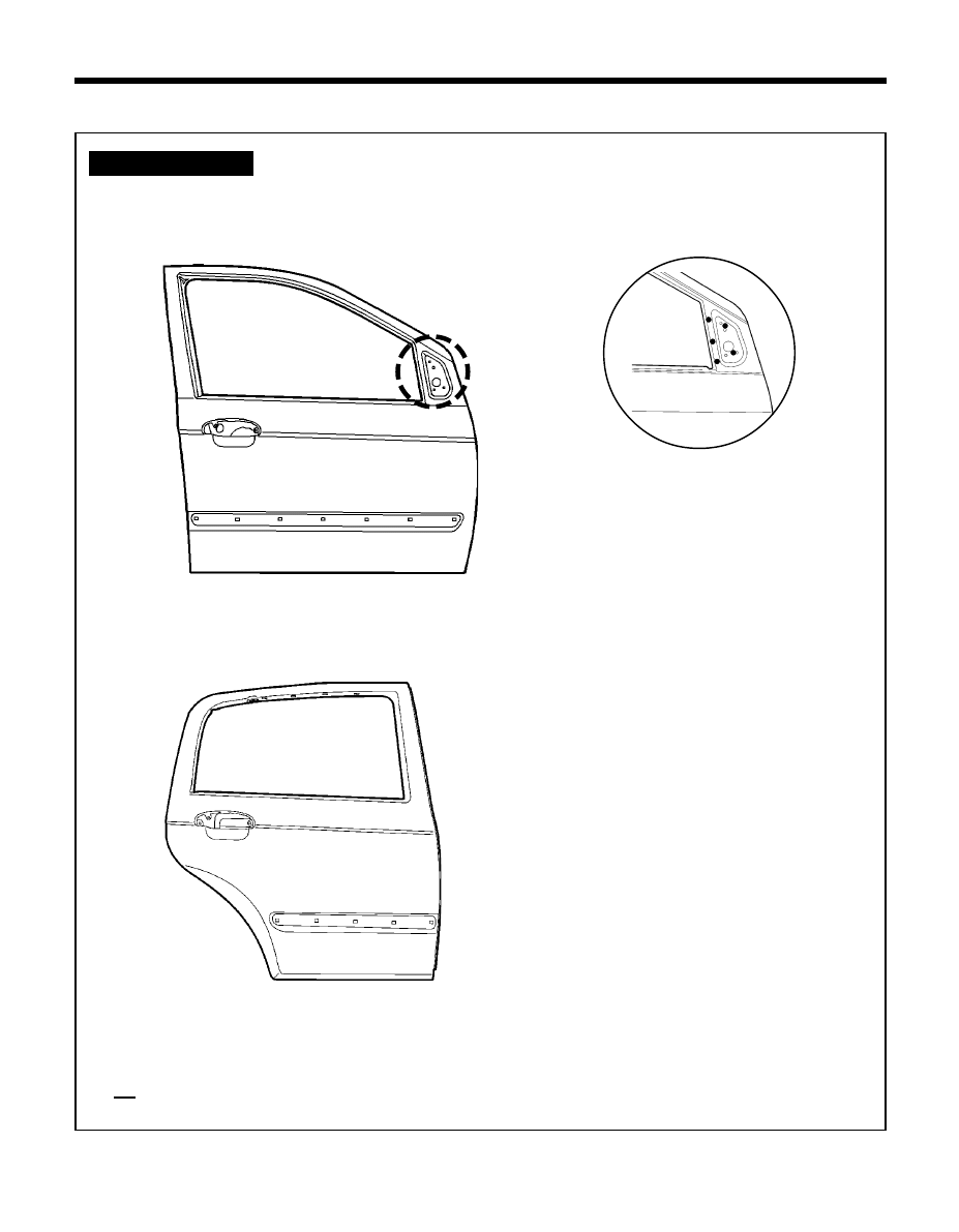
119
BODY PANEL REPAIR PROCEDURE - Front and rear door outer panels
FRONT AND REAR DOOR OUTER PANELS
WELDLING POINTS
FRONT DOOR
REAR DOOR
Ô
A
CON-0752
CON-0750
CON-0800
Ô
A
z
z
z
z
z MIG plug welding
xx MIG lap welding
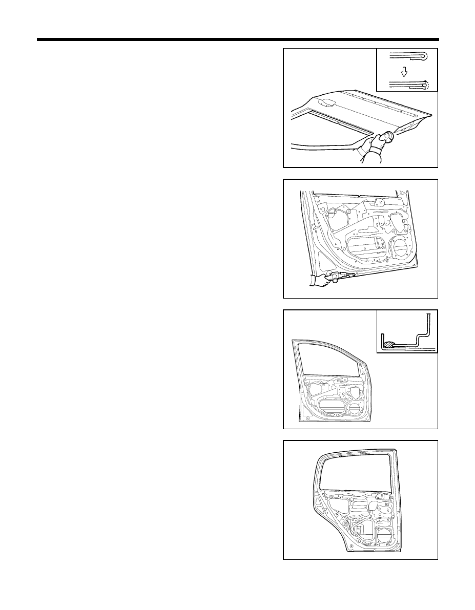
120
BODY PANEL REPAIR PROCEDURE - Front and rear door outer panels
REMOVAL
1.
Cut door outer panel hem with a sander.
2.
After grinding off the hemming location, remove the outer panel.
3.
Dress rusty part with a sander and prepare surface to be hemmed.
INSTALLATION
1.
Apply adhesive or equivalent to outer panel hem.
2.
Apply mastic sealer or equivalent to the door upper member and
door reinforcement beam as shown in the figure.
PRO-1830/PRO1831
PRO-1840
CON-1850/PRO1771
PRO-1860
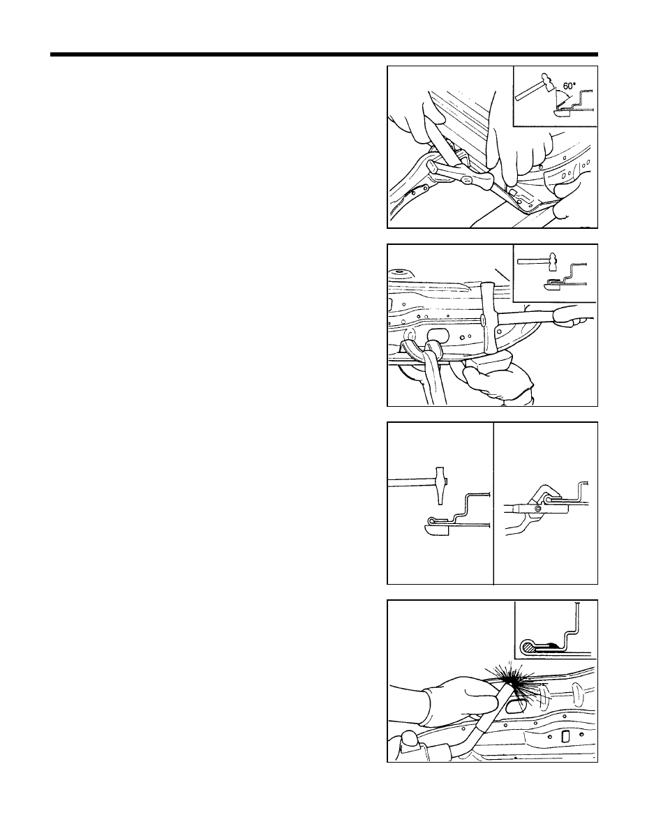
121
BODY PANEL REPAIR PROCEDURE - Front and rear door outer panels
3.
Bend the flange hem with a hammer and dolly, then fasten tightly
with a hemming tool.
NOTE
1.
Hemming work should be done in three steps as illustra-
tion.
2.
If a hemming tool cannot be used, hem with a hammer
and dolly.
4.
After completing the hemming work, make MIG spot welds at 50
mm intervals on the inside.
5.
Clean and prepare all welds, remove all residue.
6.
Apply the two-part epoxy primer to the interior of the door panel.
PRO-1880
PRO-1900
PRO-1870
PRO-2000
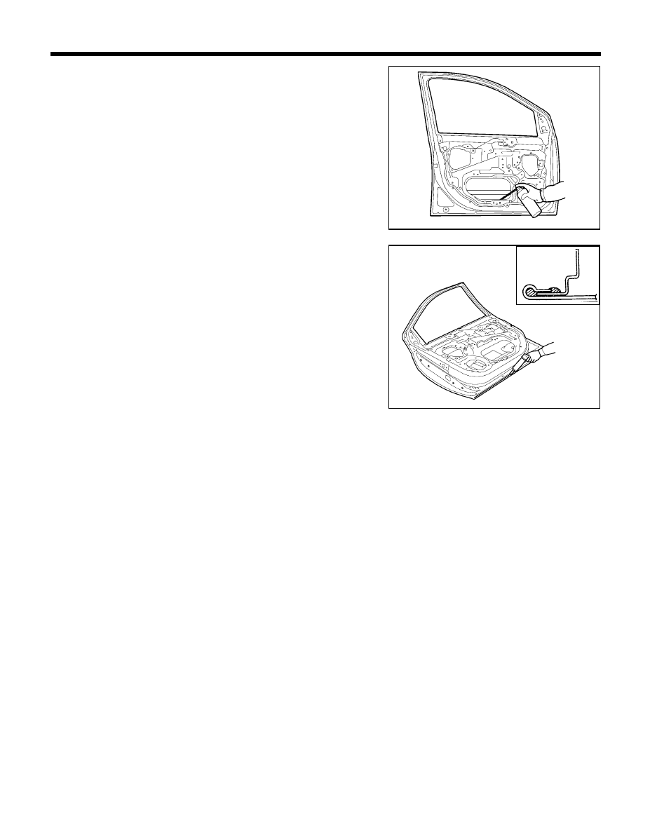
122
BODY PANEL REPAIR PROCEDURE - Front and rear door outer panels
7.
Apply an anti-corrosion agent to the welded parts and lower inside
of the door panel (Refer to the CORROSION PROTECTION).
8.
Prepare exterior surfaces for priming, using wax and grease
remover.
9.
Apply metal conditioner and water rinse.
10. Apply conversion coating and water rinse.
11. Apply the two-part epoxy primer.
12. Apply the correct seam sealer to whole panel edge.
13. Reprime over the seam sealer to complete the repair.
PRO-2010
PRO-2020/PRO-2021

BODY SEALING
LOCATIONS
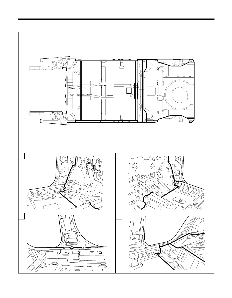
124
2
3
1
F L O O R
F L O O R
F L O O R
F L O O R
F L O O R
BODY SEALING LOCATIONS - Floor
BODY SEALING LOCATIONS - Floor
BODY SEALING LOCATIONS - Floor
BODY SEALING LOCATIONS - Floor
BODY SEALING LOCATIONS - Floor
4
SEA-0020
SEA-0030
SEA-0010
SEA-0035
SEA-0040
6
6
6
6
6
Ò
Í
1
Ñ
2
2
2
2
2
Ò
Ï
4
4
4
4
4
Ï
5
3
3
3
3
3
Î
7
7
7
7
7
Ï
8
8
8
8
8
Ï
9
9
9
9
9
14/15
14/15
14/15
14/15
14/15
12
12
12
12
12
13
13
13
13
13
Î
11
11
11
11
11
10
10
10
10
10
Ï
Ï
Ñ
Ï
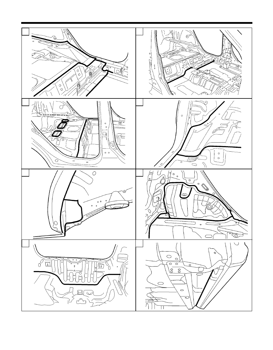
125
125
125
125
125
7
9
11
BODY SEALING LOCATIONS - Floor
BODY SEALING LOCATIONS - Floor
BODY SEALING LOCATIONS - Floor
BODY SEALING LOCATIONS - Floor
BODY SEALING LOCATIONS - Floor
10
12
8
6
SEA-0050
5
SEA-0060
SEA-0080
SEA-0070
SEA-0090
SEA-0100
SEA-0120
SEA-0110
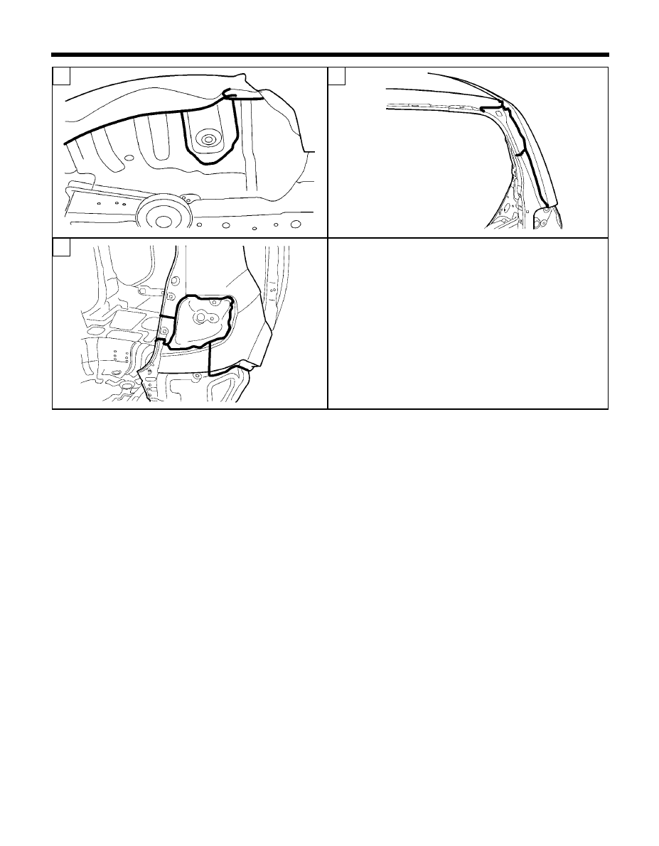
126
126
126
126
126
BODY SEALING LOCATIONS - Floor
BODY SEALING LOCATIONS - Floor
BODY SEALING LOCATIONS - Floor
BODY SEALING LOCATIONS - Floor
BODY SEALING LOCATIONS - Floor
13
14
SEA-0140
SEA-0130
SEA-0150
15
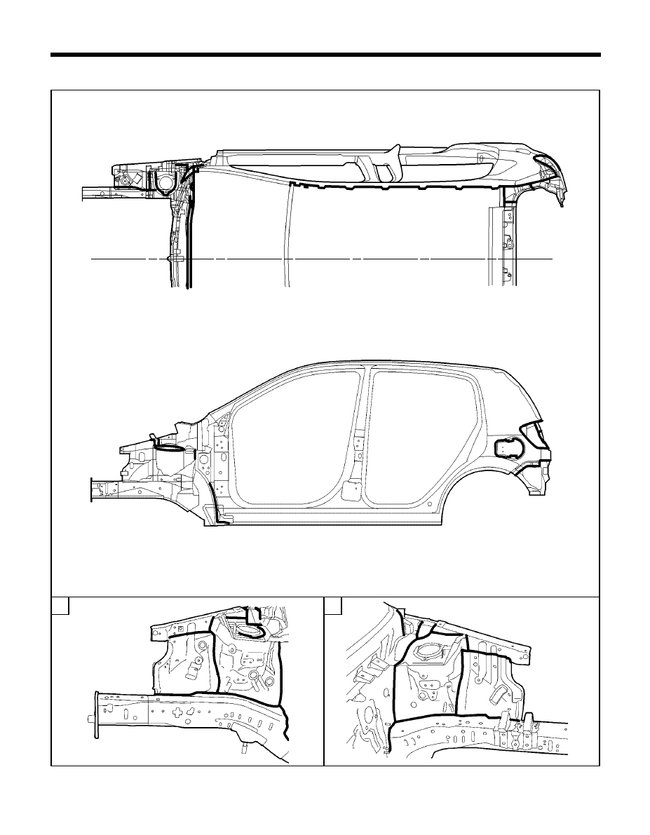
127
127
127
127
127
BODY SEALING LOCATIONS - Upper and side body
BODY SEALING LOCATIONS - Upper and side body
BODY SEALING LOCATIONS - Upper and side body
BODY SEALING LOCATIONS - Upper and side body
BODY SEALING LOCATIONS - Upper and side body
1
UPPER AND SIDE BODY
UPPER AND SIDE BODY
UPPER AND SIDE BODY
UPPER AND SIDE BODY
UPPER AND SIDE BODY
2
SEA-0160, 0170
SEA-0200
SEA-0210
Ï
Í
Í
Í
Í
Í
Ï
7
7
7
7
7
Ï
10
10
10
10
10
12
12
12
12
12
Î
13
13
13
13
13
Í
Í
Í
Í
Í
9
9
9
9
9
8
8
8
8
8
6
6
6
6
6
5
5
5
5
5
1
1
1
1
1
Ô
Ð
3
3
3
3
3
Ò
2
2
2
2
2
Ò
Ð
4
4
4
4
4
Î
11
11
11
11
11
Ð
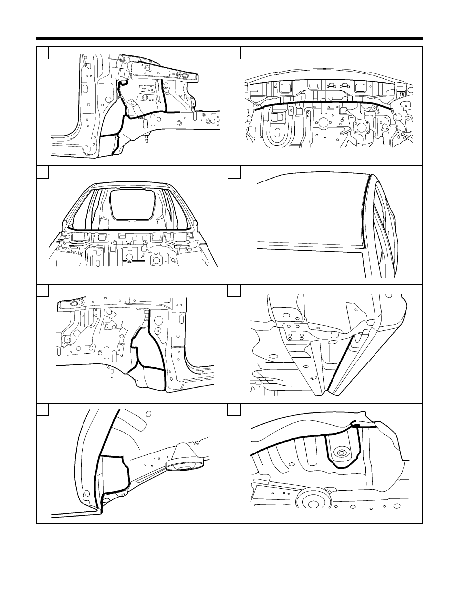
128
128
128
128
128
BODDY SEALING LOCATIONS - Upper and side body
BODDY SEALING LOCATIONS - Upper and side body
BODDY SEALING LOCATIONS - Upper and side body
BODDY SEALING LOCATIONS - Upper and side body
BODDY SEALING LOCATIONS - Upper and side body
3
5
7
6
8
10
BODY SEALING LOCATIONS - Upper and side body
BODY SEALING LOCATIONS - Upper and side body
BODY SEALING LOCATIONS - Upper and side body
BODY SEALING LOCATIONS - Upper and side body
BODY SEALING LOCATIONS - Upper and side body
9
4
SEA-0230
SEA-0220
SEA-0240
SEA-0250
SEA-0120
SEA-0130
SEA-0090
SEA-0260
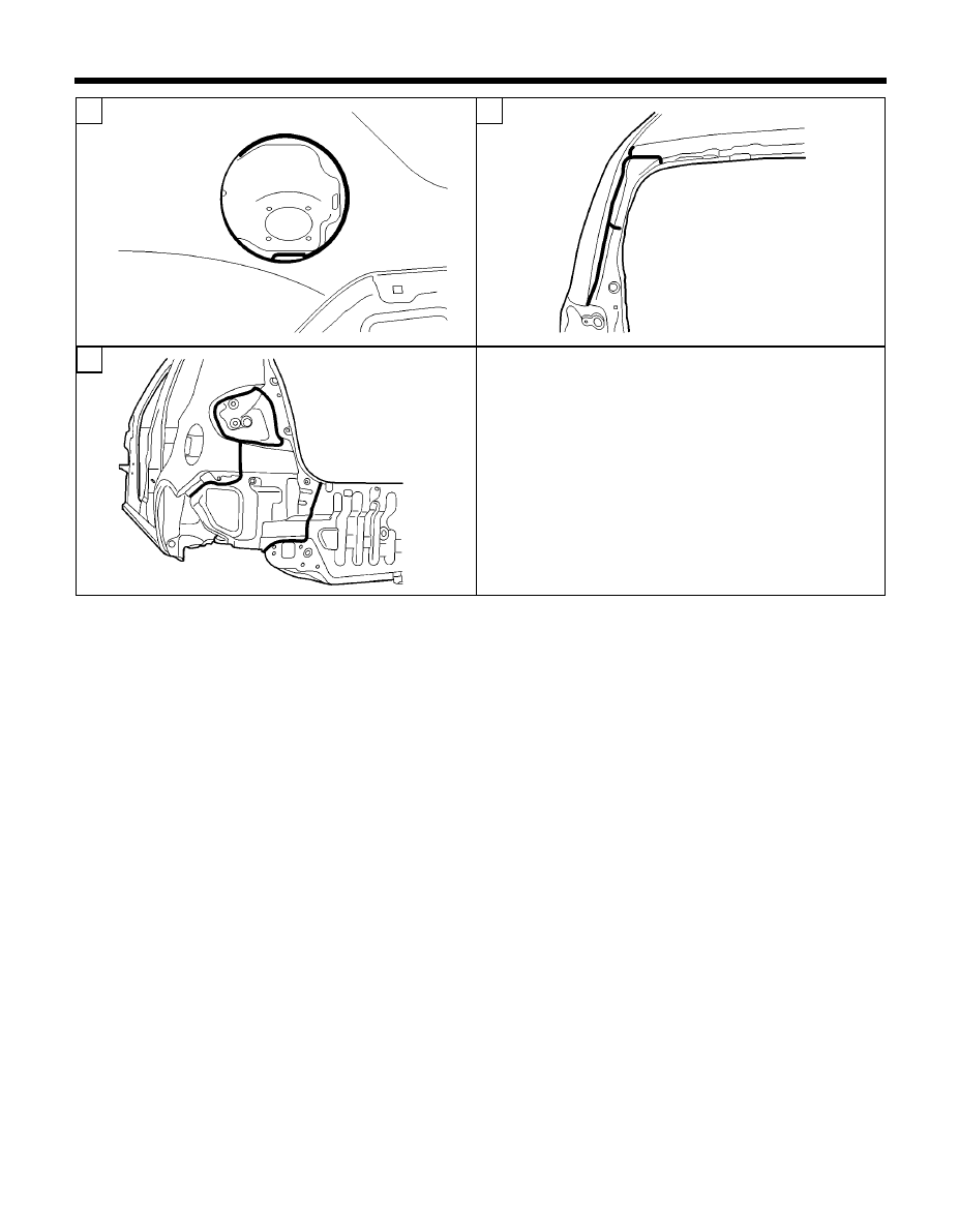
129
129
129
129
129
13
11
12
BODY SEALING LOCATIONS - Upper and side body
BODY SEALING LOCATIONS - Upper and side body
BODY SEALING LOCATIONS - Upper and side body
BODY SEALING LOCATIONS - Upper and side body
BODY SEALING LOCATIONS - Upper and side body
SEA-0320
SEA-0310
SEA-0300

CORROSION
PROTECTION
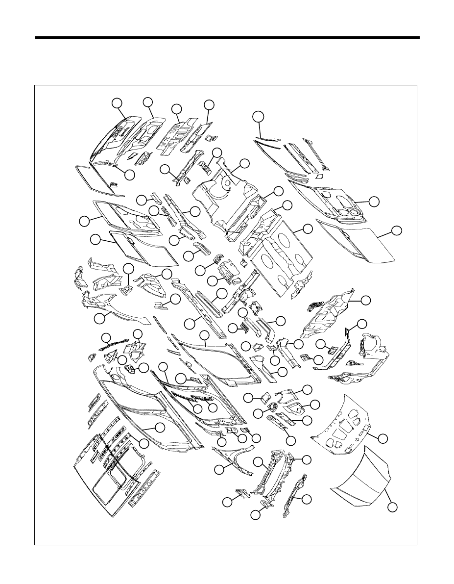
132
BODY CONSTRUCTION - Zinc-galvanized steel panels
ZINC-GALVANIZED STEEL PANELS
Because galvanized steel panel has excellent resistance, it is used in areas which have a high possibility of painting
deficiency below.
TB-50
13
10
52
66
67
11
12
15
16
17
18
20
21
22
23
6
4
5
7
3
2
1
62
63
65
64
25
24
56
60
54
55
53
49
50
51
48
46
44
47
42
45
43
40
35
41
36
39
37
38
26
31
32
28
30
27
29
33
34
19
58
59
68
61
8
9
57
14

133
BODY CONSTRUCTION - Zinc-galvanized steel panels
1. Radiator support upper center panel
2. Radiator support center reinforcement
3. Dash panel
4. Center floor panel
5. Rear floor extension
6. Rear floor front cross member
7. Rear floor panel
8. Towing hook bracket
9. Rear floor center cross member
10. Rear transverse member
11. Back panel
12. Tail gate inner panel
13. Tail gate outer panel
14. Rear door frame rear reinforcement
15. Rear door inner panel
16. Rear door outer panel
17. Rear floor side member extension
18. Rear floor side member reinforcement
19. Rear floor side member
20. Trailing arm mounting reinforcement
21. Rear floor side front member
22. Parking brake cable mounting bracket
23. Parking brake aperture panel
24. Center floor side member
25. Side sill inner panel
26. Side inner panel
27. Front side rear member
28. Front side rear lower reinforcement
29. Front side rear lower member
30. Front side member rear lower extension
31. Front side outer member
32. Transmission mounting bracket
33. Front side inner member
34. Battery tray leg reinforcement
35. Fender apron inner front panel
36. Fender apron inner panel
37. Cowl under cover extension
38. Front shock absorber cover panel
39. Fender apron upper member
40. Apron upper reinforcement
41. Hood inner panel
42. Hood outer panel
43. Cowl inner lower panel
44. Cowl side outer panel
45. Cowl top outer panel
46. Cowl side upper outer member
47. Cowl inner rear panel
48. Fender panel
49. Front door upper mounting reinforcement
50. Front pillar outer bracket
51. Front door lower mounting bracket
52. Side outer panel
53. Side outer reinforcement
54. Center pillar outer upper reinforcement
55. Center pillar outer lower reinforcement
56. Rear door lower mounting bracket
57. Fuel filler housing
58. Quarter outer rear lower extension
59. Quarter outer rear upper extension
60. Rear combination lamp housing panel
61. Side roof rear lower reinforcement
62. Quarter inner panel
63. Rear spring house cover
64. Wheel house inner front extension
65. Wheel house inner panel
66. Front door outer panel
67. Front door inner panel
68. Front door frame rear reinforcement
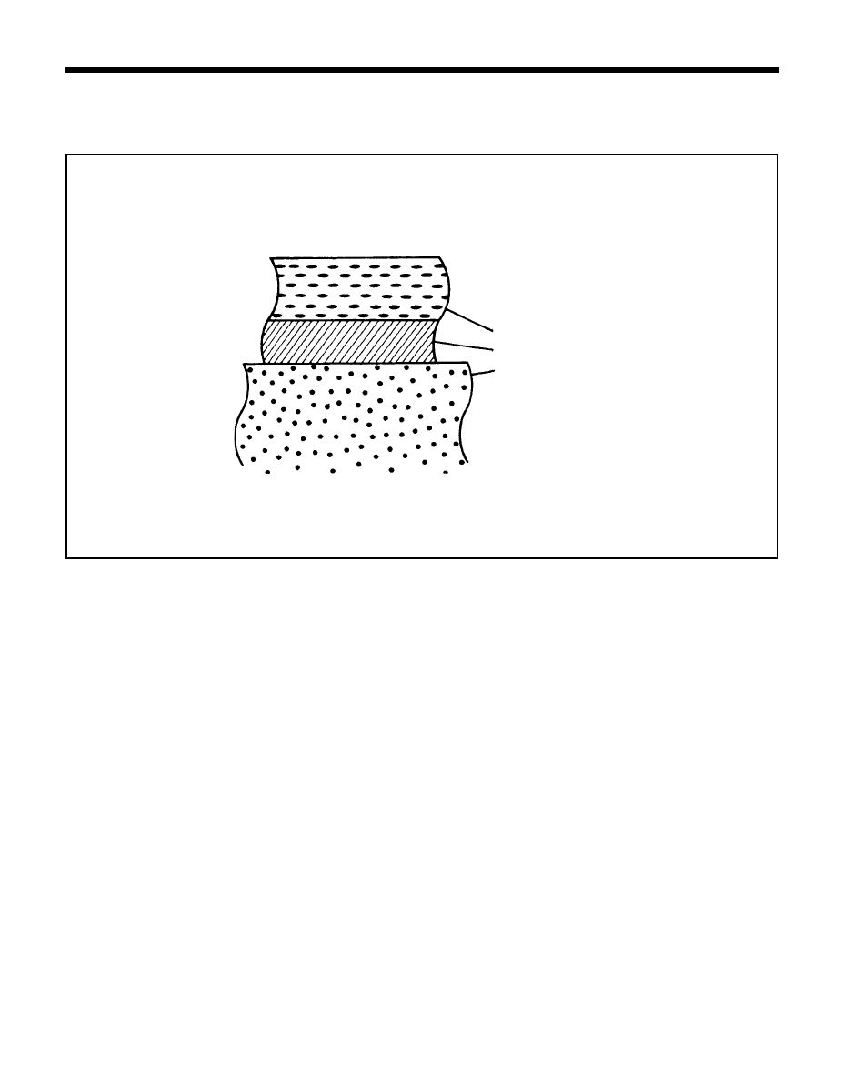
134
ZINC-PHOSPHA
ZINC-PHOSPHA
ZINC-PHOSPHA
ZINC-PHOSPHA
ZINC-PHOSPHATE CO
TE CO
TE CO
TE CO
TE COA
A
A
A
AT & CA
T & CA
T & CA
T & CA
T & CATIONIC ELECTR
TIONIC ELECTR
TIONIC ELECTR
TIONIC ELECTR
TIONIC ELECTRODEPOSITION PRIMER
ODEPOSITION PRIMER
ODEPOSITION PRIMER
ODEPOSITION PRIMER
ODEPOSITION PRIMER
In order to improve the adhesion of the paint coat on the steel panel, and also to improve the corrosion resistance, the entire
body is coated with a film of Zinc-phosphate and a cationic electrodeposition primer.
CORROSION PROTECTION - Zinc-phosphate coat & cationic eletrodeposition primer
Body steel panel
Zinc-phosphate film
Cationic electrodeposition primer
COR-0020
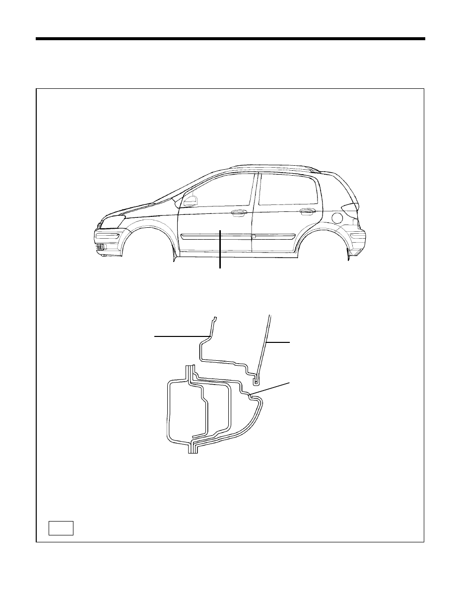
135
ANTI-CORROSION PRIMER
ANTI-CORROSION PRIMER
ANTI-CORROSION PRIMER
ANTI-CORROSION PRIMER
ANTI-CORROSION PRIMER
An anti-corrosion primer has been applied to the side sill outer panel for the purposes of corrosion prevention and abrasion
protection. If this panel is replaced, apply an anti-corrosion primer between the undercoat and the intermediate coat, as
shown in the following illustrations.
Rock panel primer (Thickness 180
µ
~ 200 µ
)
CORROSION PROTECTION - Anti-corrosion primer
TB-133-2
A
A'
Í
Í
SECTION A-A'
Front & rear door outer
panel
Side sill outer panel
133-1
Door inner panel
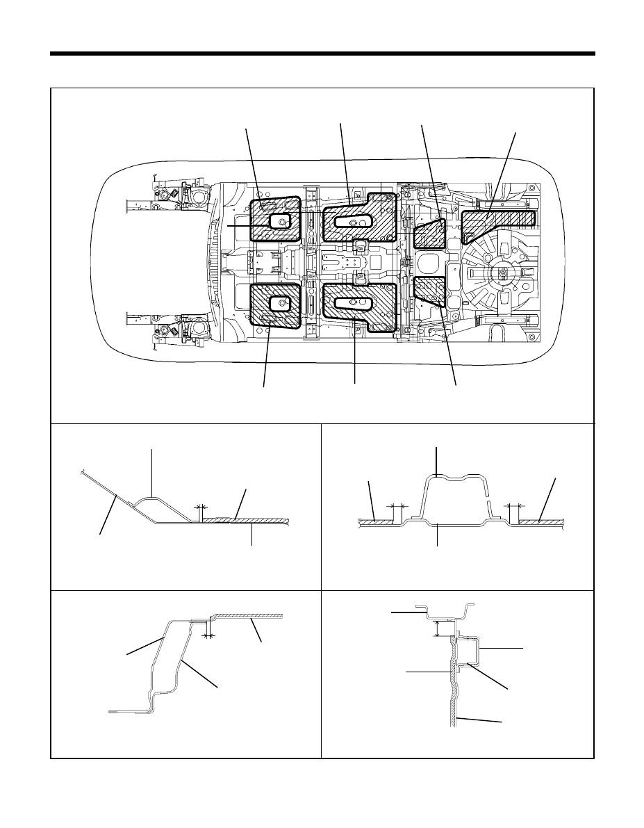
136
CORROSION PROTECTION - Antivibration pads
ANTIVIBRATION PADS-LOCATION & SECTION
SECTION A-A'
SECTION B-B'
SECTION C-C'
SECTION D-D'
ANT-0002
ANT-0003
ANT-0004
ANT-0005
ANT-0001
Ï
A
A'
Ï
C
Í
C'
Í
Ï
B
B'
Ï
Ï
D
D'
Ï
84152-1C000
84186-1C000
84156-1C000
84187-1C000
84151-1C000
84155-1C000
84185-1C000
Dash panel
Dash lower reinforcement
84151/52-1C000
Center floor panel
Center floor panel
84151/52-1C000
Front seat cross member
84155/56-1C000
3mm
15mm
15mm
Rear floor extension
7mm
Rear floor panel
84155/56-1C000
Rear floor front
cross member
84156/55-1C000
Center floor panel
Rear floor side
front member
Center floor side
member
Side sill inner
panel
44.5mm
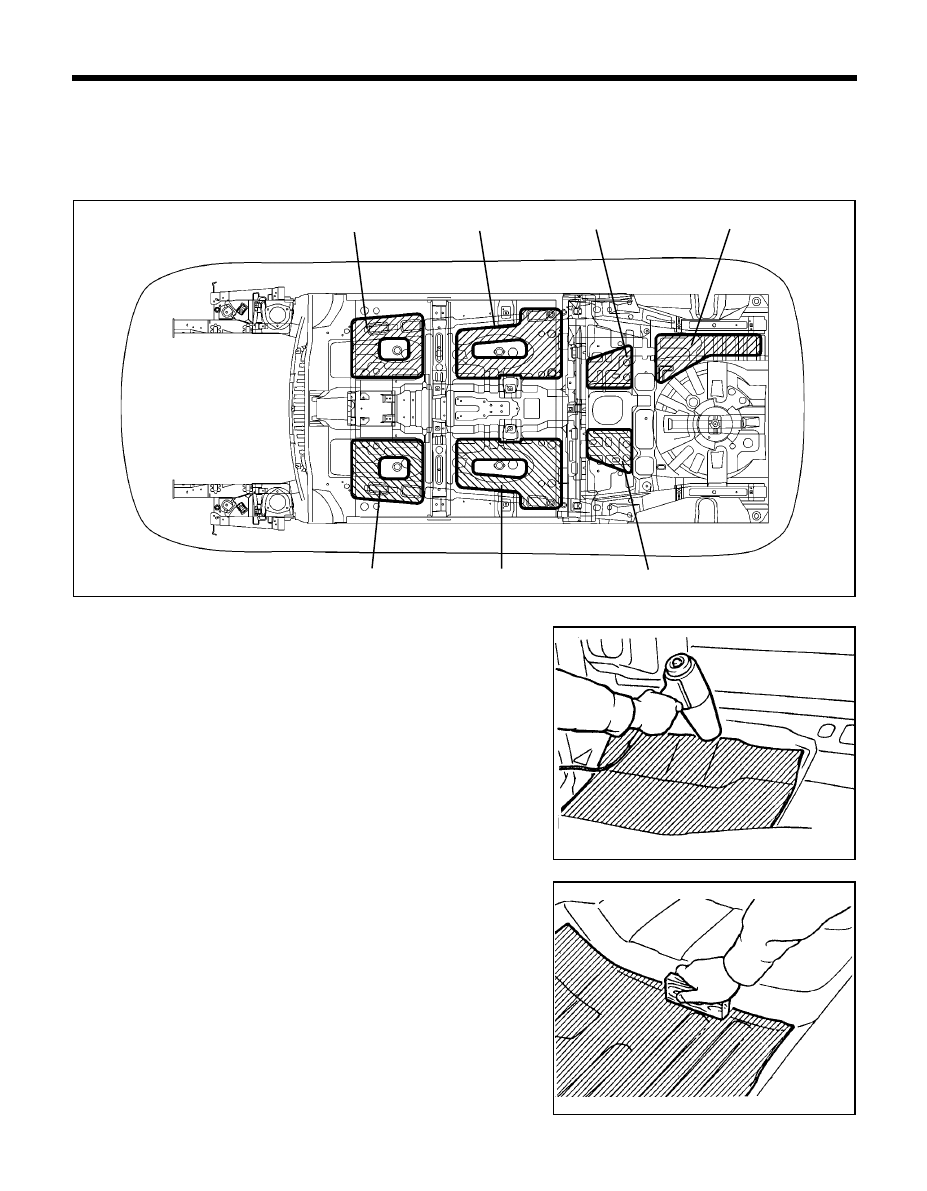
137
CORROSION PROTECTION - Attachment of antivibration pads
ANT-0001
ATTACHMENT OF ANTIVIBRATION PADS
Antivibration pads are attached to the upper surface of the floor and at the interior side of the dash panel in order to absorb
vibrations and shut out exhaust gas heat. If these antivibration pads are peeled off in the course of replacement or repair
of a welded panel, cut and attach replacement material (in the shape shown in the figure).
1.
Heat the "antivibration pad" with a blow drier to soften it.
2.
Align the antivibration pad layer in the position where it is to be
installed, and then press it down with a roller or a block of wood
so that it adheres well.
NOTE
An infrared lamp can also be used to heat both the antivibration
pad layer and the body panels(be sure to wear gloves).
COR-0006
COR-0007
84152-1C000
84186-1C000
84156-1C000
84187-1C000
84151-1C000
84155-1C000
84185-1C000
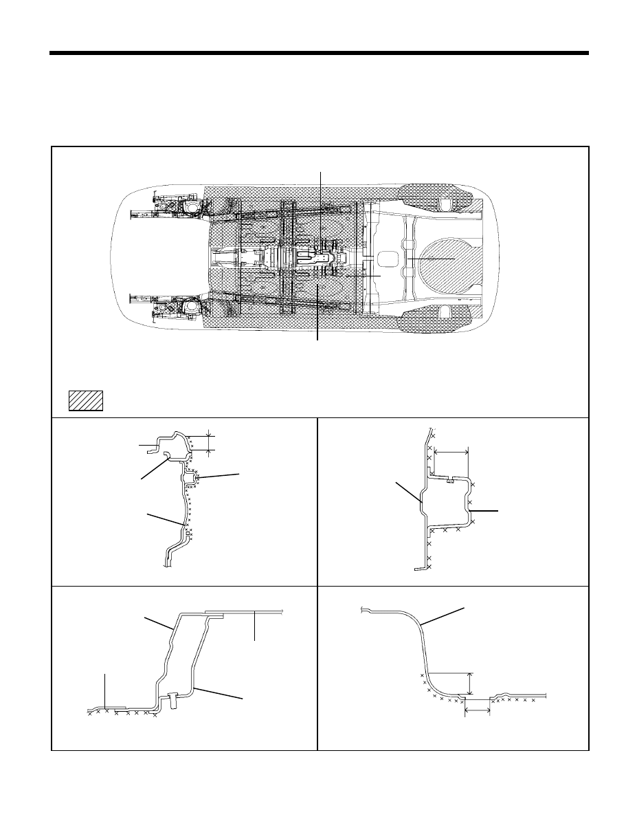
138
SECTION D-D'
SECTION A-A'
SECTION C-C'
Under body coating (Thickness 0.8 mm - 2.0 mm)
CORROSION PROTECTION - Under body coat
TB-134
SECTION B-B'
Because parts are to be mounted in these locations, mask the location, before applying
the under body coat.
134-1
134-2
134-3
134-4
A
A'
C'
C
Í
Í
B
B'
D'
UNDER BOD
UNDER BOD
UNDER BOD
UNDER BOD
UNDER BODY CO
Y CO
Y CO
Y CO
Y COA
A
A
A
AT
T
T
T
T
In order to provide corrosion, stone chipping and vibration resistance, under body coat is applied to the under sides of the
floor and wheel house.
Therefore, when such panel is replaced or repaired, apply under body coat to that part.
FLOOR
D
Í
Í
Í
Í
Í
Í
Side outer panel
Center floor panel
Center floor side
member
Center floor panel
Center floor side
member
Rear floor panel
70mm
ø
50 must be masking
ø
60 must be masking
60mm
Rear floor extension
Center floor panel
Rear floor panel
Rear floor front
member
Side sill inner panel
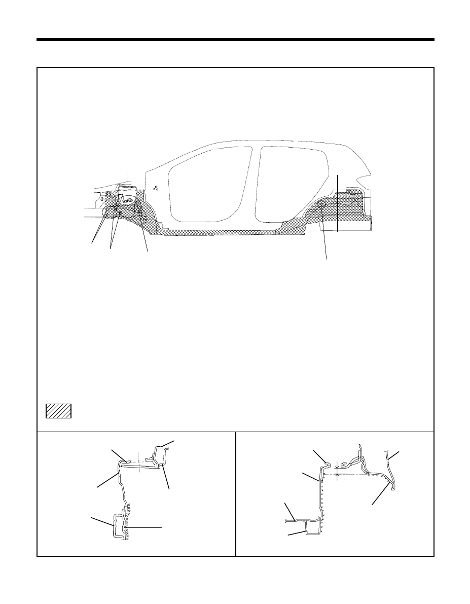
139
SIDE BOD
SIDE BOD
SIDE BOD
SIDE BOD
SIDE BODY
Y
Y
Y
Y
SECTION A-A'
CORROSION PROTECTION - Under body coat
135-1
SECTION B-B'
A
A'
Î Î Î Î Î
Î Î Î Î Î
Î Î Î Î Î
Î Î Î Î Î
135-2
TB-135
Because parts are to be mounted in these locations, mask the location before applying
the under body coat.
Under body coating (Thickness 1.0 mm - 2.0 mm)
B'
B
Front shock absorber
cover panel
Fender apron
upper member
Front apron inner panel
Front side inner
panel
Front side outer panel
Rear spring cover bracket
Wheel house inner panel
Rear floor panel
Rear floor side
member
30mm
Side outer
panel
Quarter inner panel, LH
Fender apron upper
reinforcement
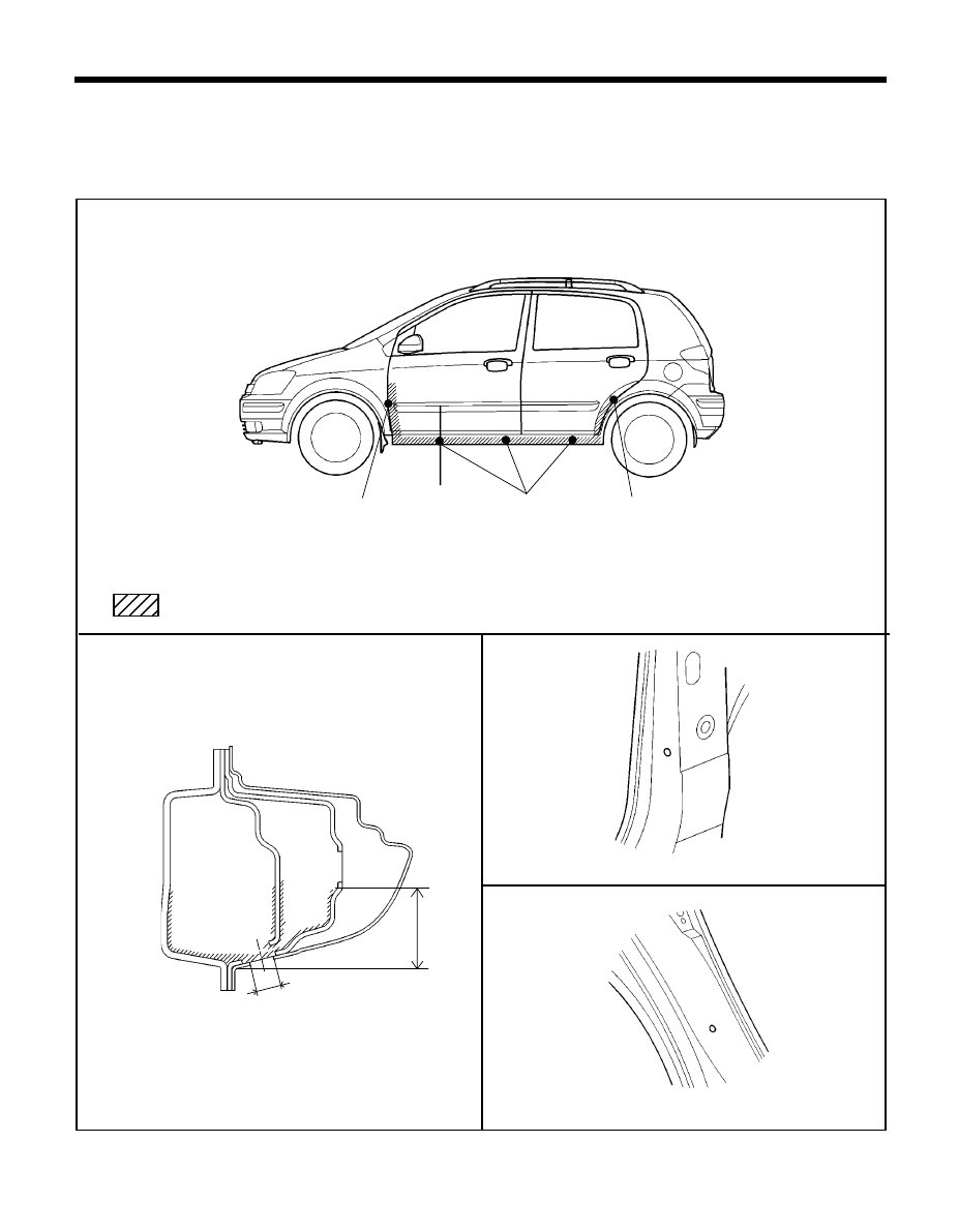
140
VIEW "B"
CAVITY WAX INJECTION
In order to provide greater corrosion resistance, cavity wax injection has been performed for the lower areas of the
vehicle, such as the sidemember, the side sill and the inside of other panels which are a hollow construction.
When replacing these parts, be such to apply cavity wax to the appropriate areas of the new parts.
CORROSION PROTECTION - Cavity wax injection
SECTION A-A'
VIEW "C"
Wax injection must be done through access holess marked.
COR-0031
COR-0033
COR-0030
50mm
Cavity wax injection (Thickness 40
µ
- 50
µ
)
A
Ï
A'
(MIN)
Ï
COR-0032
"B"
Ï
"C"
Ï
ø
13mm
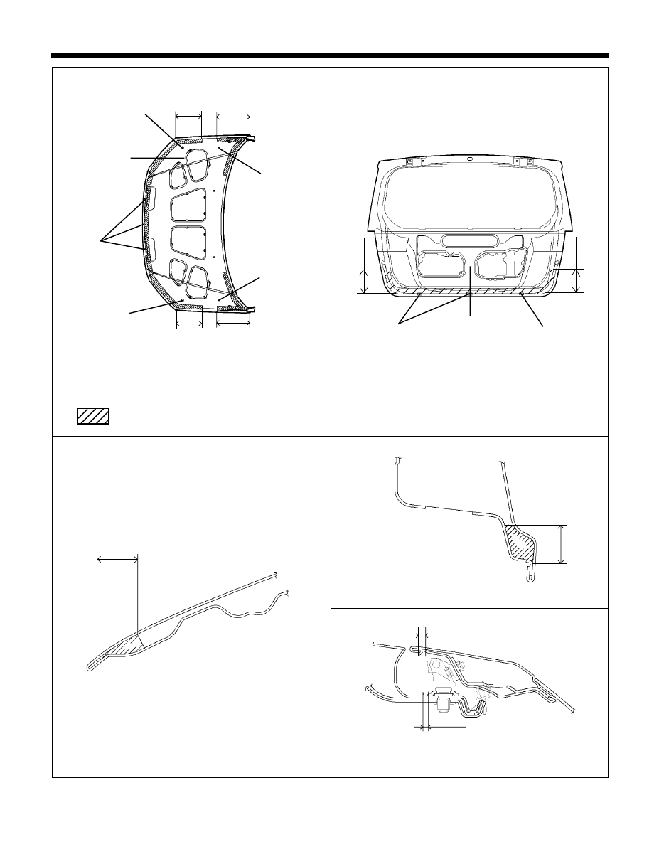
141
CORROSION PROTECTION - Cavity wax injection
SECTION A-A'
SECTION B-B'
Wax injection must be done through access holes marked.
COR-0041
COR-0051
COR-0040/0050
Cavity wax injection (Thickness 40
µ
- 50
µ
)
SECTION C-C'
COR-0052
30mm
Í
Í
A
A'
B
B'
Í
150mm
HOOD
TAIL GATE
30mm
(MIN)
200mm 250mm
200mm 250mm
Í
(MIN)
150mm (MIN)
(MIN)
5mm
(MIN)
5mm
(MIN)
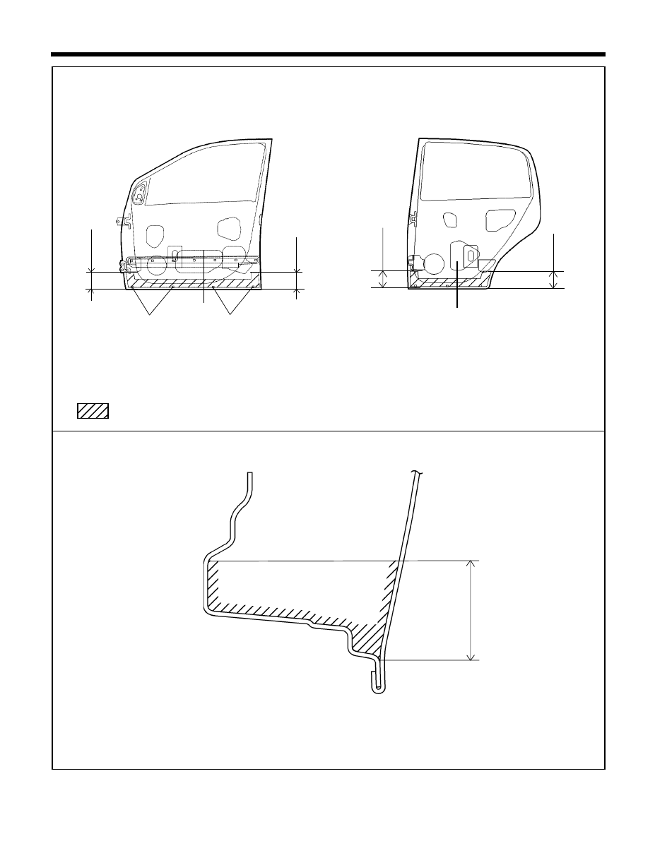
142
CORROSION PROTECTION - Cavity wax injection
Wax injection must be done through access holes marked.
COR-0060/0070
Cavity wax injection (Thickness 40
µ
- 50
µ
)
SECTION A-A'
A
Í
A'
Í
130mm
(MIN)
130mm
(MIN)
REAR DOOR
FRONT DOOR
A
Í
A'
Í
130mm
(MIN)
130mm
(MIN)
COR-0062
60mm
(MIN)
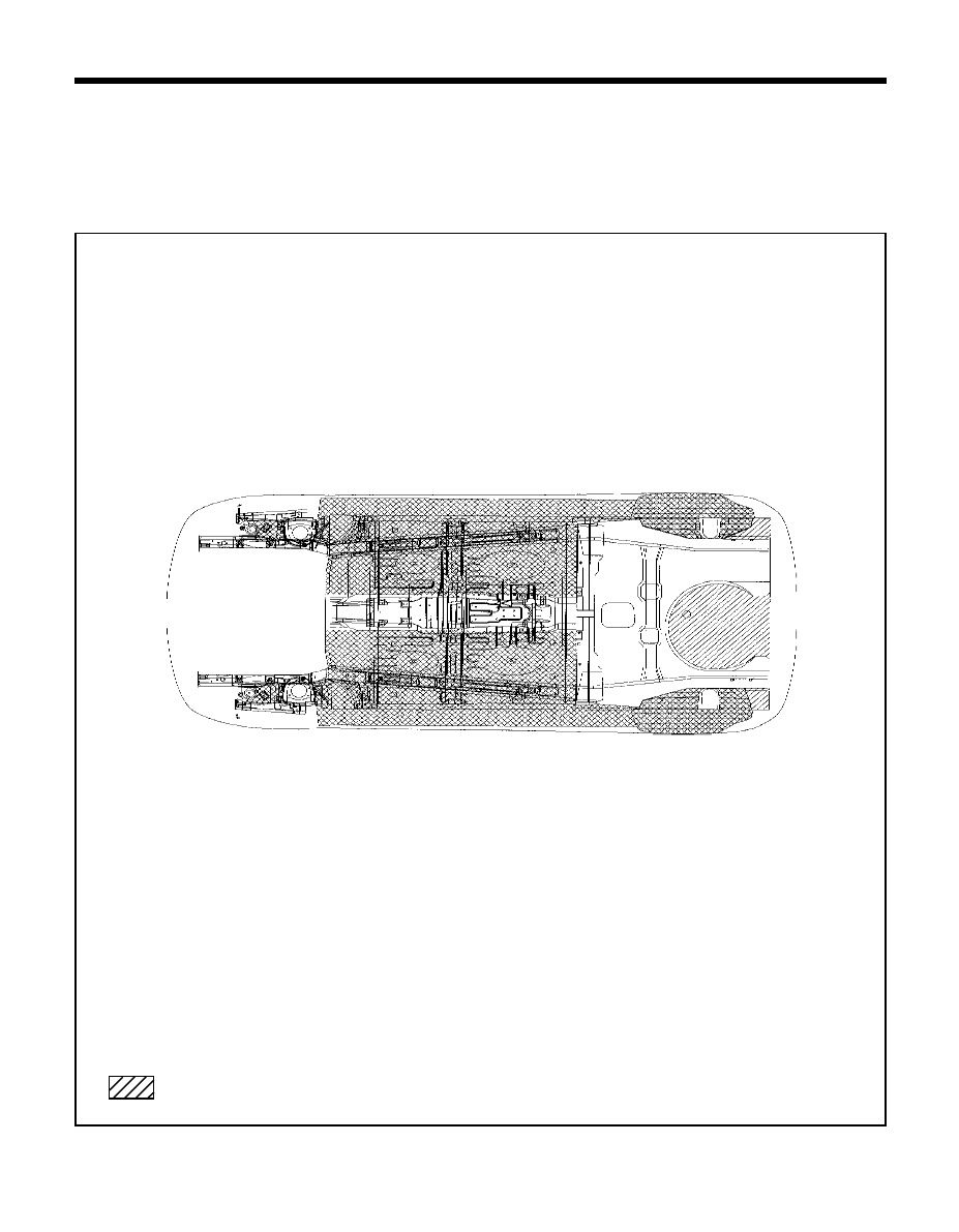
143
CORROSION PROTECTION - Under body anti-corrosion agent
CORROSION PROTECTION - Under body anti-corrosion agent
CORROSION PROTECTION - Under body anti-corrosion agent
CORROSION PROTECTION - Under body anti-corrosion agent
CORROSION PROTECTION - Under body anti-corrosion agent
UNDER BOD
UNDER BOD
UNDER BOD
UNDER BOD
UNDER BODY ANTI-CORR
Y ANTI-CORR
Y ANTI-CORR
Y ANTI-CORR
Y ANTI-CORROSION A
OSION A
OSION A
OSION A
OSION AG E N T
G E N T
G E N T
G E N T
G E N T
The undersides of the floor and wheel house are undercoated to provide greater corrosion resistance. Therefore, when
such panel is replaced or repaired, apply under body anti-corrosion agent to that part.
NOTE
Do not apply the under body anti-corrosion agent to come in contact with tires, muffler and exhaust pipe.
TB-134
Under body anti-corrosion agent (Thickness 0.8 ~ 2.0mm)
Wyszukiwarka
Podobne podstrony:
Repair Manual Collision?maged Body (BRM075)
Canon Ef 28 135 Repair Manual
Canon Speedlite 580EX Repair manual
Canon Ef 70 200 2 8 L Usm Repair Manual
Canon Ef 28 2 8 (Type 1, 2) Repair Manual
Canon Speedlite Macro Twin Lite Mt 24Ex Repair Manual
KTM 250 525 SX MXC EXC 2003 Repair Manual
Canon Extender Ef 1 4X Repair Manual
Canon Ef 300 2 8 L Is Usm Repair Manual
Canon Speedlite 380Ex Repair Manual
Canon EF 300 4 0 L USM Repair Manual
Canon EF 70 200 2 8 L IS USM Repair Manual
Canon Ef 50 1 4 Usm Repair Manual
Canon EF 200 2 8 L Repair Manual
Canon EF 85 1 2 L Repair Manual
Canon EXTENDER EF 2X Repair Manual
więcej podobnych podstron