IWK keyboards can be used for remote
access of IWP series power board functions
by displaying functional parameters and the
operating temperature.
The Split version of the Wide device consists
of two units:
• an IWK keyboard available in several sizes*
• an IWP power module.
The IWK keyboard is connected to the IWP
power module via a “powered” serial con-
nection.
*Different IWK keyboard models are
available: this technical data sheet
describes the wide format IWK key-
board. For information on other key-
boards, refer to the relevant technical
data sheets.
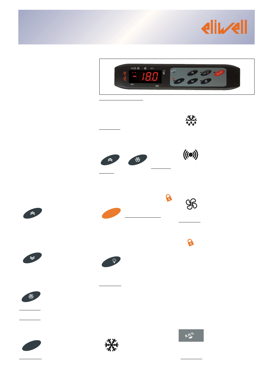
USER INTERFACE
The wide IWK keyboard is conceived as a
keyboard with a 6 LED display, 6 keys and
5 more LEDS for controlling instrument
status and programming.
KEYS AND MENUS
UP key
• Scrolls the menu items
• Increases values
• can be associated with a direct func-
tion
DOWN key
• Scrolls the menu items
•Decreases values
• can be associated with a direct func-
tion
ESC key
(press once)
•ESC function (quit)
(hold down)
•activates manual defrosting if specified*
*(see IWP board instructions)
Set point key
(press once)
MACHINE STATUS MENU
•Accesses set point
•Displays alarms (if present)
•Displays any probe values*
*(see IWP board instructions)
(hold down)
Accesses keyboard local parameter pro-
gramming menu
UP key+ESC key pressed simultaneously
(press for 2
seconds)
•Locks/unlocks keyboard NOTE: To indi-
cate that the keyboard is locked, the Lock
LED lights up.
On-off key (STAND-BY)
(press for 2 seconds)
• Switches device on/”off”
(the device remains on (on STAND-BY) the
on-off LED lights up and the display is
switched off
AUX/LIGHT key
• The auxiliary relay/light
is activated (1)
•fan forcing ON (if enabled) (2)
(IF PRESENT)
—>aux/light (1) or R.H.% (2) LED lights up
LED (ON DISPLAY)
eco
(Set point/Reduced set
point)
•ON to modify Set-Point;
•blinking when reduced set point is
entered
Compressor
•ON when compressor is on;
•blinking for delay, protection or enabling
blocked
Defrosting
•ON when defrosting is in progress;
•blinking when dripping is in progress
Alarm
•ON for active alarm;
•blinking when a silenced alarm is still
present (NOTE: silencing the alarm only
removes the acoustic signal (buzzer, if
present)
Fans
•ON when fan is on;
(IF PRESENT)
LED (ON KEYBOARD)
lock
•ON for lock (keyboard locked);
on/off
•ON when unit is “off” (on
STAND-BY);
•OFF when unit is on;
“manual defrosting”
•ON for manual defrosting
“aux/light”
•ON for active output
NOTE: ON when output is also active
from D.I. (Digital Input)
“R.H. %”
•ON for key fan forcing*•OFF normal fan
operating*
*(IF PRESENT)
set
on/o
ff
aux
IWK wide
wide format panel keyboard for IWP boards
cod. 9IS43076
rel. 11/07 ENG

PLEASE NOTE: the LEDS are OFF in any
other circumstances not described here
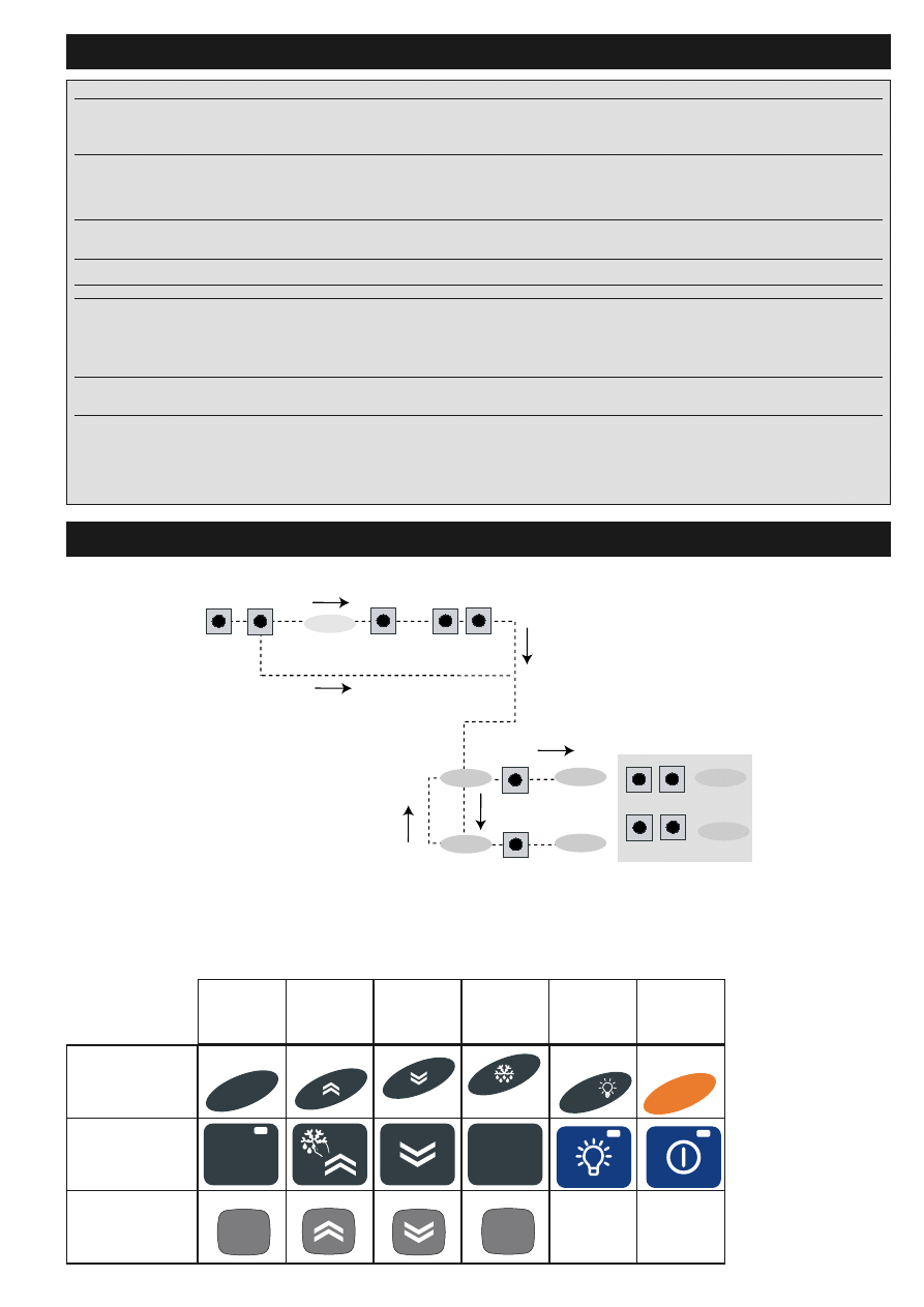
ACCESSING AND USING MENUS
LOCAL KEYBOARD PROGRAMMING
MENU
Hold down the “UP” and “DOWN” keys for
at least 3 seconds to access the “Keyboard
Local Programming” menu. If specified, the
access PASSWORD will be requested (see
parameter “PA3”) and, if the password is
correct, the PLO (Local Parameters)
label will appear. This folder contains
the keyboard local parameters (see
Keyboard Local Parameters table).
If the password is incorrect, the display
will show the PA3 label again. NOTE: the
folder may NOT be visible; if this is the
case, keyboard local programming can-
not be accessed)
To enter the folder, press “set”. The label
of the first visible parameter will appear.
To scroll through the other parameters,
use the “UP” and “DOWN” keys.
To change the parameter, press and
release “set”, then set the desired value
using the “UP” and “DOWN” keys and con-
firm with the “set” key. Move on to the
next parameter.
PLEASE NOTE: We strongly recommend
that you switch the instrument off and on
again each time parameter configuration is
changed in order to prevent malfunction-
ing of the configuration and/or ongoing
timings.
KEYBOARD LOCAL PASSWORD
Password “PA3” allows access to the key-
board local parameters. This password is
not present in the standard configuration.
To enable it (value<>0) ) and assign it the
required value, access the “Keyboard Local
Programming” menu in the “PLO” folder.
If the password is enabled, it will be
requested when entering the “PLO” menu.
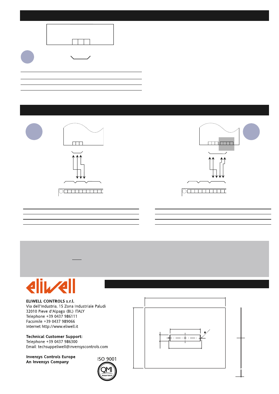
INSTALLATION
The unit has been designed to be panel-
mounted: Drill a 150x31 mm hole (see
CUT-OUT diagram) and insert the device
fixing it on the front using the special
screws supplied.
Do not install the keyboard in excessively
humid and/or dirty locations. It is suitable
for use in locations with normal pollution
levels.
Always make sure that the area next to the
unit cooling slits is adequately ventilated.
IWK wide
2/4
RESPONSIBILITY AND RESIDUAL RISKS
Eliwell & Controlli s.r.l. shall not be liable
for any damages deriving from:
- installation/use other than that prescribed
and, in particular, which does not comply
with the safety standards specified in the
regulations and/or those given herein;
- use on equipment that does not guaran-
tee adequate protection against electric
shock, water or dust when assembled.
- use on equipment that allows dangerous
parts to be accessed without the use of
tools;
- tampering with and/or alteration of the
product;
- use on equipment that does not comply
with the standards and regulations in force.
DISCLAIMER
This document is exclusive property of
Eliwell & Controlli s.r.l. and cannot be
reproduced and circulated unless
expressly authorized by Eliwell &
Controlli s.r.l.. Although Eliwell &
Controlli s.r.l. has taken all possible
measures to guarantee the accuracy of
this document, it declines any responsi-
bility for any damage arising out of its
use.
The same applies to any person or com-
pany involved in preparing and writing
this manual. Eliwell & Controlli s.r.l.
reserves the right to make any changes
or improvements without prior notice
and at any time.
CONDITIONS OF USE
PERMITTED USE
For safety reasons the instrument must
be installed and used in accordance with
the instructions supplied. Users must not
be able to access parts with dangerous
voltage levels under normal operating
conditions.
The device must be adequately protected
from water and dust depending on the
specific application and only be accessi-
ble using special tools (except for the
front panel).
The device is ideally suited for household
use and/or similar use in the refrigera-
tion sector and has been tested with
regard to safety in accordance with the
European harmonized reference stan-
dards:
It is classified as follows:
• as an automatic electronic control
device to be mounted as regards its con-
struction;
• as a 1 B type operated control device
as regards its automatic operating fea-
tures;
• as a Class A device as regards the cate-
gory and structure of the software.
UNPERMITTED USE
The use of the unit for applications other
than those described is forbidden.
IWK WIDE KEYBOARD TECHNICAL DATA
Casing: PC+ABS UL94 V-0 resin plastic body, polycarbonate front, thermoplastic resin
keys.
Dimensions: front 180x37 mm, depth 23 mm.
Mounting: on panel, with drilling template 150x31 (+0.2/-0.1 mm).
Operating temperature: -5…55 °C.
Storage temperature: -30…85 °C.
Usage ambient humidity: 10…90 % RH (non-condensing).
Storage ambient humidity: 10…90% RH (non-condensing).
Display range: –50…110 °C (NTC)*, –55…140 °C (PTC)* without decimal point, on display
3 digits + sign.
Measurement range: from -55 a 140 °C.
Accuracy: better than 0.5% of bottom scale +1 digit.
Resolution: 1 or 0.1 °C.
Analogue Inputs, Digital Inputs and Outputs: on associated IWP power board
Serials: see Associated IWP Power Board Technical Data Base
Board-Keyboard Connection: via “powered” serial using +12V, GND and DATA lines
Consumption: see Associated IWP Power Board Technical Data
Power supply: 12V
cfrom IWP power module.
ELECTRICAL
WIRING
Warning! Always switch off machine before working on electrical connections.
Make sure that the power voltage complies with the device voltage. Serial cables
should be kept separate from the power cables.
IWK wide
3/4
KEYBOARD PARAMETERS
KEYBOARD LOCAL PARAMETER MENU DIAGRAMS
PLO
LiC
level par
level par
PA3≠0
set PA3 value
change
par value
scroll
parameters
press simultaneously
for 3 sec
UP
DOWN
ENTER
UP DOWN
ENTER
ENTER
UP DOWN
UP DOWN
PARAMETER
ECO
adb
PA3
rEL
toA
Li1
tbA
* DEFAULT column: The term default identifies the standard factory-set configuration;
(!) CAUTION!
• We strongly recommend that you switch the instrument off and on again each time parameter configuration is changed in order to prevent malfunctioning of the con-
figuration and/or ongoing timings.
DESCRIPTION
ECO (folder with “PLO” label)
Type of keyboard
0= Master keyboard
1= ECO keyboard address base.
Base address. By changing the address of the power board in
a LINK, this parameter can be used to logically connect the
keyboard to a different power board so that menu naviga-
tion, parameter programming, etc is possible.
Keyboard PAssword. When enabled (value is not 0) it repre-
sents the access key for the local keyboard parameters.
reLease firmware. Device version: read only parameter.
time-out Address. tbA address timeout.
LiC (folder with “LiC” label)
Broadcast communication n= keyboard communicates with
adb address base (see.)(in this case, there are several bases);
y= keyboard communicates with broadcast address base (in
this case, there is only one base).
Temporary navigation base address. Temporary address for
network navigation.
-1= disabled
DEFAULT*
0
0
0
0
10
n
0
R
RA
AN
NG
GE
E
0...1
0...4
0...255
0...999
0...250
n/y
-1…4
U.M.
num
num
num
num
sec
num
num
set
aux
on/off
set
esc
set
fnc
wide keyboard
6-key open
keyboard
32x74 keyboard
set
UP
DOWN
ESC
aux/light
on/off
IWK wide
4/4
IWK wide KEYBOARD CONNECTIONS
TERMINALS
“POWERED” SERIAL
1 GND
2 12V
3
DATA
1 2 3
KEYBOARD IWK wide
D
ATA
GND
12V
Serial
screw ter-
minals
1 2 3
IWK "wide"
1
2
3
4
5
6
7
8
9 10
GND
485-
485+
+12V
GND
DA
T
A
VDD
GND
BASE BOARD
485-
485+
DA
T
A
GND
12V
1 2 3
IWK "wide"
LONG DIST ANCE
1
2
3
4
5
6
7
8
9 10
GND2
485-
485+
+12V
GND1
DA
T
A
VDD
GND2
LONG DISTANCE
12V
GND
485-
485+
DA
T
A
BASE BOARD
485-
485+
4 5 6 7
485-
485+
Link Plus seri-
al connection
Link Plus 485
“Long distance”
serial connection
(optional for
semi-finished
product)
NOTE : BASE UNIT/KEYBOARD CONNECTION/PROGRAMMING.
1 — THE BASE UNIT/KEYBOARD PROGRAMMING/CONFIGURATION CANNOT BE CARRIED OUT IF THE DEVICES ARE CONNECTED TO THE LINK
NETWORK. THEREFORE, IT IS FIRST NECESSARY TO CONFIGURE THE MASTER AND SLAVE DEVICES (WITH RELATED KEYBOARDS) AND THEN
CONNECT THEM TO THE LINK NETWORK.
2 — “FLICKERING” OF THE DISPLAYS ON THE KEYBOARD INDICATES THAT THE CONNECTED UNITS ALL HAVE THE SAME ADDRESS: DISCON-
NECT THE LINK NETWORK AND PROGRAM EACH UNIT AS DESCRIBED ABOVE.
Link Plus Serial Connection
+12V
12V - power supply
GND
GND - powered serial connection
DATA
DATA - powered serial connection
485 Long Distance serial connection
VDD
12V Power supply
GND
RS485 Serial connection
485-
485- RS485 Serial connection
485+
485+ RS485 Serial connection
BASE UNIT/KEYBOARD WIRING
400
150
163
31
2.4 (x 2)
A
(A) PANEL THICKNESS 0.5-1-1.5-2-2.5-3 mm
300
CUT OUT
11/2007 -ENG-
cod. 9IS43076
Wyszukiwarka
Podobne podstrony:
IME WIDE
Module 4 of 5 (Wide Area Networking)
BMW E38 E39 Wide Screen Monitor Service Manual
Cutting Wide Boards On A Table Saw
ime wide sontag
Katy Perry Wide Awake
Spread Wide Secretary
LAOWA 15mm f 4 Wide Angle 1 1 Macro Lens Venus Optics Anhui ChangGeng Optical Technology Company L
wide angle tables
Anitra Lynn McLeod Gridiron Gods 07 Wide Receiver
Wide Oscar ZBRODNIA LORDA ARTURA SAVILE A
Genome wide mapping of gene–microbiota interactions in susceptibility to autoimmune skin blistering
49 Pentatonix As Long As You Love Me, Wide Awake
Snicket Lemony A Series Of Unfortunate Events 03 The Wide Window
42 foot wide pole utility building
The Water is Wide inst in C
więcej podobnych podstron