Page 1
www.shoestringastronomy.com
Modification of a EQ-style
Dual Axis Controller to Add
an Autoguider Port
Revision 1.0
Copyright 2004, Shoestring Astronomy

Page 2
INTRODUCTION
The EQ-style telescope mount series are some of the most widely sold
mounts in the world. Various companies such as Celestron and Orion
sell versions of these mounts. They are all produced by Synta.
By adding on the motor and handcontroller accessories that are available for these
mounts, long-exposure manually-guided astrophotography can be performed. However,
these handcontrollers do not include autoguider ports so that computer driven
autoguiding can be utilized.
There is no standardized autoguider port that is common to all manufacturers, but the so-
called ST4 port is a very common format used on most scopes.
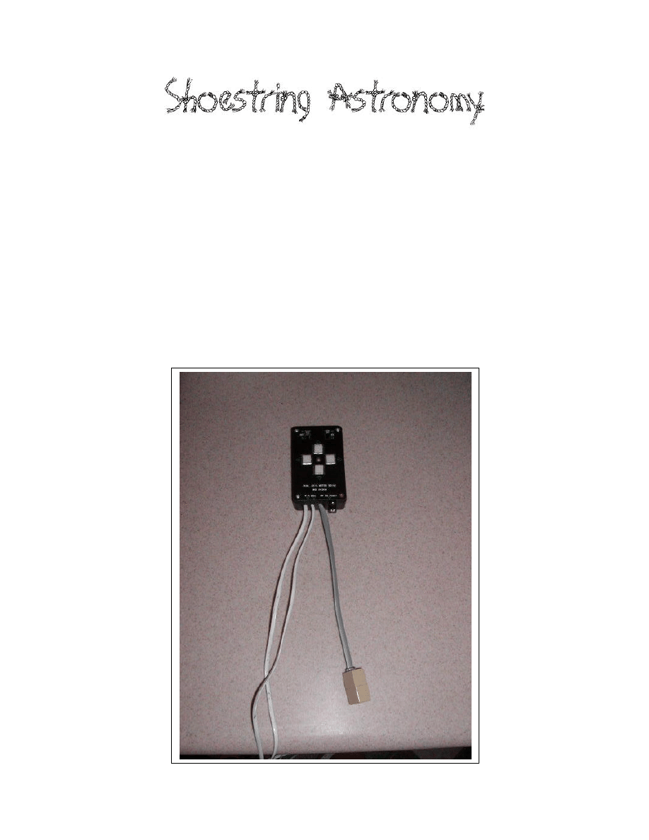
These instructions document a procedure that was used to modify an EQ3 dual-axis
handcontroller to add an ST4-style autoguider port. The CG-5 mount that it was attached
to was then successfully used to perform astrophotography using GuideDog software
from barkoSoftware (
www.barkosoftware.com
). Guiding error was kept below +/- 4 arc-
seconds. Besides your modified handcontroller and the guiding software, you will need a
suitable webcam, a computer near your telescope, a guide port interface such as model
GPINT-PT from Shoestring Astronomy, and a cable to go from the interface to the
handcontroller. Shoestring Astronomy also sells a kit with the parts you will need to
make this modification.
If you own one of these styles mounts, and are comfortable with opening up the
handcontroller box and making some simple modifications, then read on! If you are not
comfortable doing this, maybe you have a friend that is. Webcam autoguiding is an
inexpensive way to eliminate the monotony of manually autoguiding.
Read through these instruction entirely prior to beginning the modification. Make sure
you understand what must be done, and are completely comfortable with doing it.
WARNING
Performing this modification will void your warranty. Do not proceed
if you are not comfortable with this. Also, all work should be
performed by a person who knows how to solder, and at a workstation
that is electrostatic-discharge (ESD) safe. Failure to do so may result in
permanent damage to your handcontroller. This procedure is not
particularly difficult, but should not be performed by someone
unfamiliar with electronic assembly.
Page 3
TOOLS and SUPPLIES NEEDED
o
Kit of parts GPKIT-EQ from Shoestring Astronomy or equivalent.
o
7/32” nutdriver
o
7/32” drill bit
o
Drill
o
Tweezers
o
Two flat screwdrivers
o
Small Phillips screwdriver
o
Solder iron
o
Eutectic solder
PROCEDURE
1) Test your handcontroller using your scope mount and the power pack first to make
sure it is functioning properly prior to making any changes.
2) Unplug the handcontroller from the scope mount and the power pack.
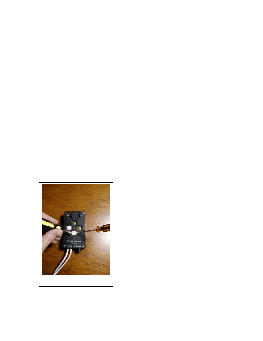
3) Carefully remove the four directional control button caps. Using two flat
screwdrivers inserted from opposite sides as shown in Figure 1, gently pry up evenly
from both sides until the button cap pops loose.
Figure 1 - Removing the button caps
Page 4
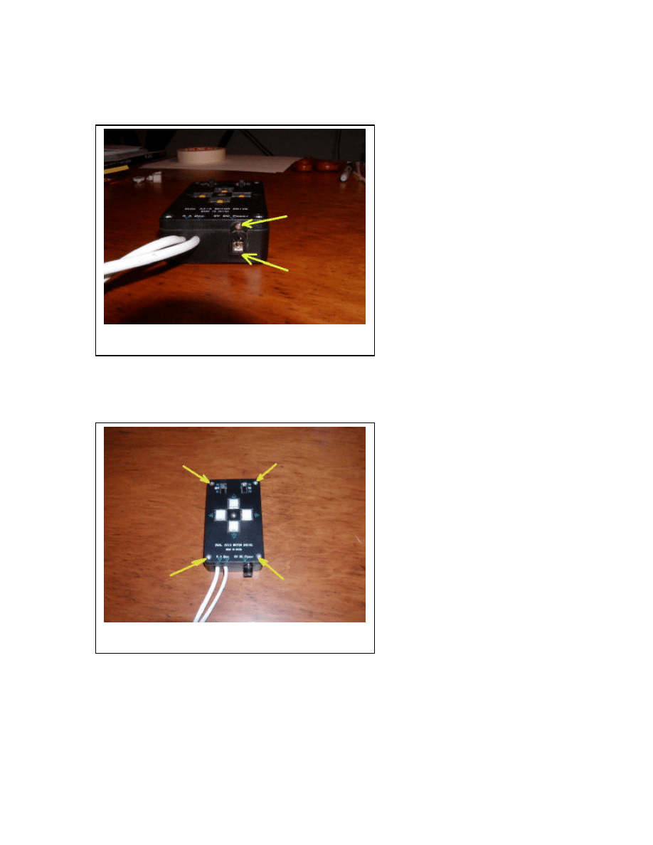
4) Remove the two screws on the lower side of the handcontroller that hold the power
jack in place, see Figure 2.
5) Remove the four screws that hold the top cover, see Figure 3.
6) Remove the cover.
Figure 2 – The power jack screws
Figure 3 – The four cover screws
Page 5
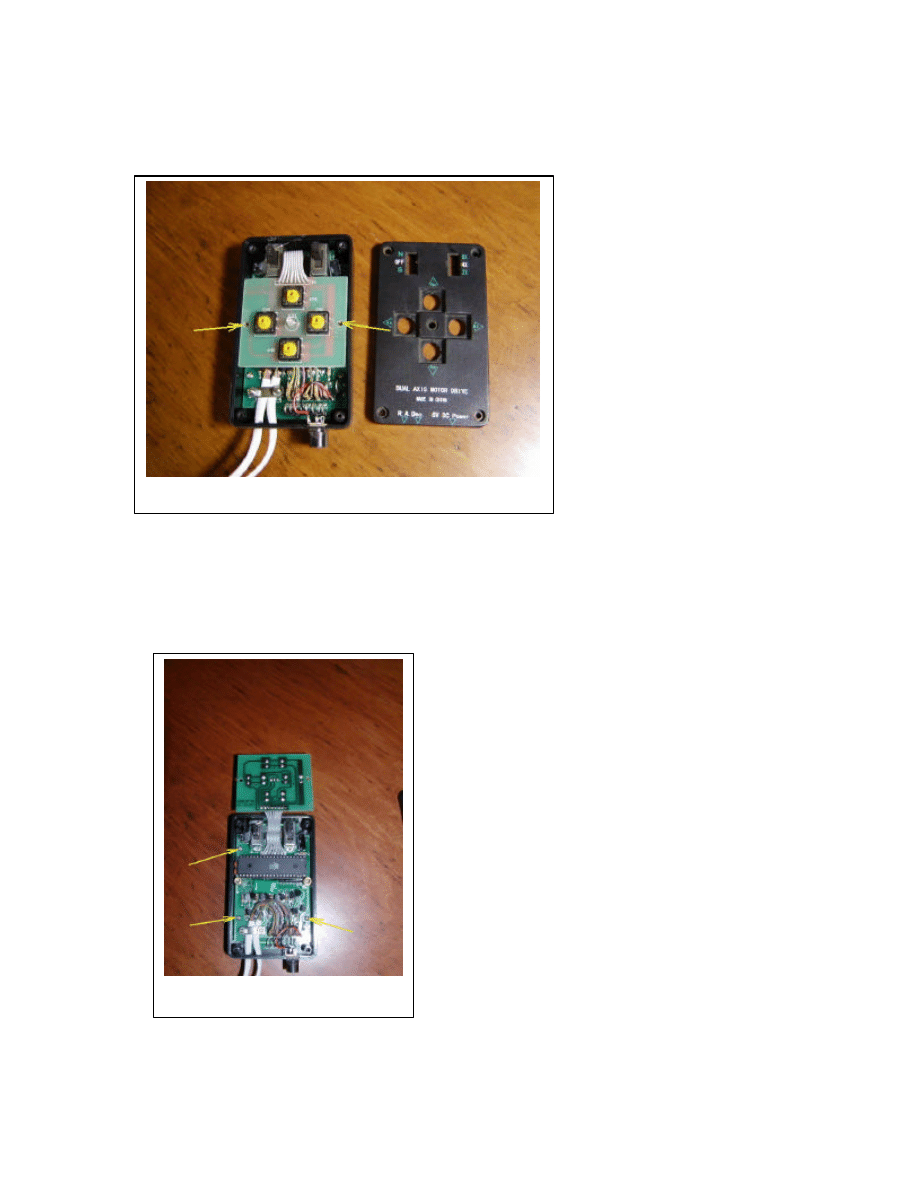
7) Remove the two screws that hold the keypad in place, see Figure 4.
8) Flip the keypad over.
9) Remove the three screws that hold the main board, see Figure 5.
Figure 4 – The keypad screws
Figure 5 – The main board screws
Page 6
10) Carefully lift the main board out. You may need to pull some of the motor cable
through their holes to do this.
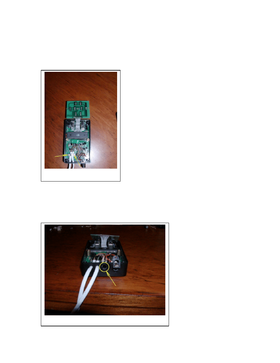
11) Using a nutdriver from the top, and a screwdriver from the bottom, remove the two
screws that hold the cable strain relief in place, see Figure 6.
12) Drill a 7/32” hole in the lower side of the enclosure in the location shown in Figure
7. While drilling, hold all parts internal to the handcontroller out of the way so that they
will not be damages when the drill bit comes through the enclosure. This step is best
performed with the help of another person.
Figure 6 – The strain relief screws
Figure 7 – Location of drilled hole
Page 7
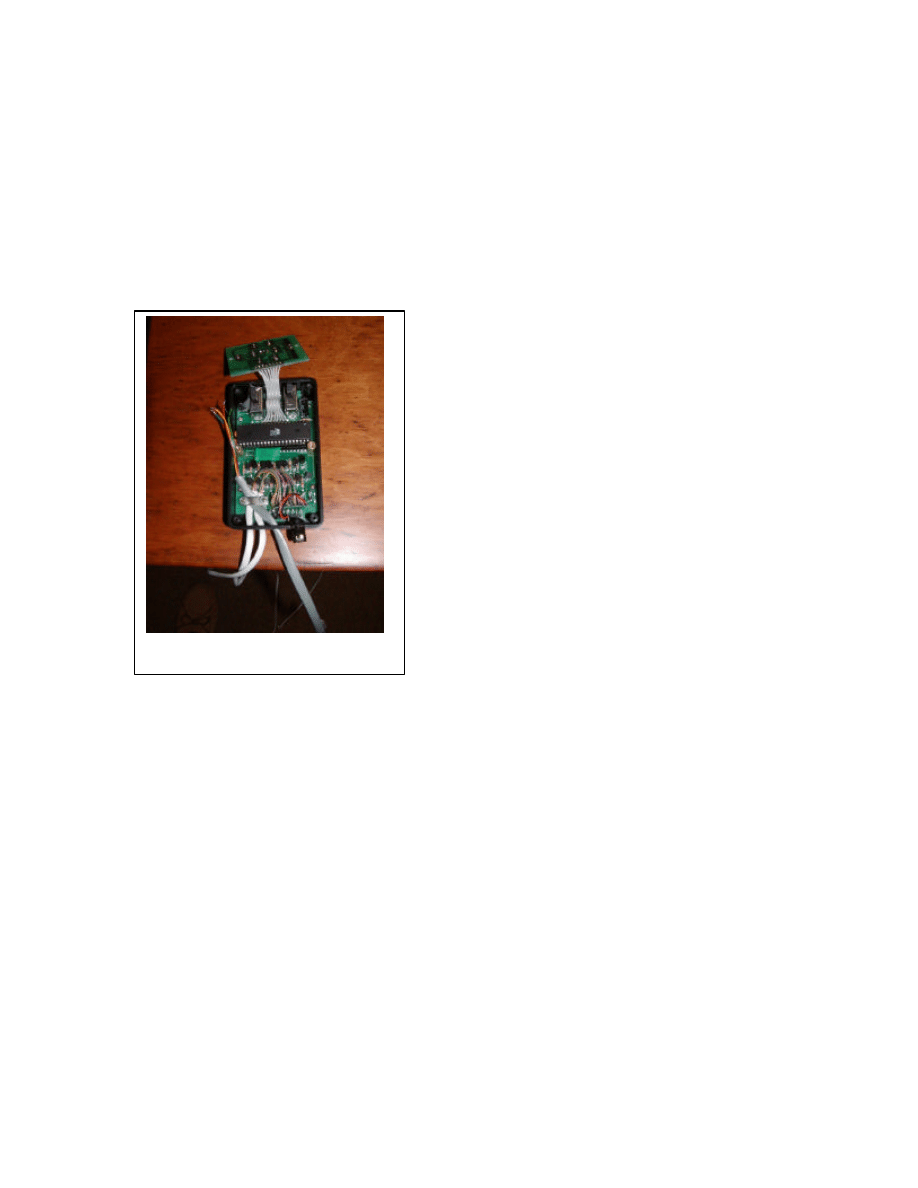
13) Push the stripped end of the cable from the parts kit through the hole far enough so
that you can still keep the main board flipped up.
14) Using the original screws and nuts, replace the strain relief bar with all three cables
underneath it as shown in Figure 8. You should leave about 4 inches of the new cable out
past the strain relief so that it will easily reach to the keypad.
15) Put the main board back in place and replace the three screws that held it down. Pull
the cables back out through their holes as necessary.
Figure 8 – Cable inserted and secured
Page 8
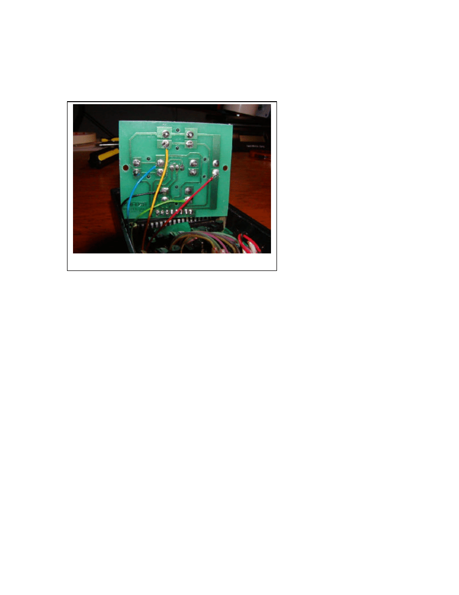
16) Solder the five wires that come out of the end of the new cable to the locations on the
underside of the keypad board as shown in Figure 9. There is a sixth wire in the cable,
but it is unused and has been trimmed back.
If you are not using the kit from Shoestring Astronomy, here is the way the cable wires
must be attached. Note the colors detailed here may not correspond to any cable other
that the one included in the Shoestring Astronomy kit.
Pin 1 – White – not used, be sure it is properly trimmed so that it will not short to
anything.
Pin 2 – Black – Common
Pin 3 – Red – RA+
Pin 4 – Green – Dec+
Pin 5 – Yellow – Dec-
Pin 6 – Blue – RA-
17) Put the keyboard back in place and screw it down with the two original screws.
18) Hook the box up to the telescope mount and power pack and test its operation prior
to completing the rest of the re-assembly. First test that all four directional pushbuttons
still work. Now, test the autoguide port by using the checkout procedure in the Guide
Port Interface Adapter (GPINT-PT) User Manual. Make sure that you start the
GuideDog software and properly set up and initialize the parallel port prior to connecting
the guide port interface adapter to the scope mount. This connection is made by attaching
the cable coupler that comes with the kit to the end of the guide port cable you have just
added, then running another cable (available from Shoestring Astronomy) from the
coupler to the guide port interface adapter. Once it appears that everything is operating
properly, remove the connections to the scope mount, power pack, and interface adapter,
and continue to re-assemble the handcontroller.
Figure 9 – Location of where to solder the wires

Page 9
19) Replace the cover and screw it down with the four original screws.
20) Replace the two power jack screws.
21) Carefully align and snap down the four directional control buttons.
22) Hook the box up to the telescope mount and power pack again and test for proper
operation as explained in step 18.
23) Go out and enjoy your autoguided scope mount!!
DISCLAIMER
This document is intended to be a guideline only. Shoestring Astronomy will not be held
responsible for any direct or consequential damage that may result while or from making
this modification. This work will be done completely at the owner’s risk.
Wyszukiwarka
Podobne podstrony:
więcej podobnych podstron