BRAKE SYSTEM
H6.00-7.00XL (H135-155XL,
H135-155XL
2
) [F006, G006]
PART NO. 897109
1800 SRM 327

SAFETY PRECAUTIONS
MAINTENANCE AND REPAIR
• When lifting parts or assemblies, make sure all slings, chains, or cables are correctly
fastened, and that the load being lifted is balanced. Make sure the crane, cables, and
chains have the capacity to support the weight of the load.
• Do not lift heavy parts by hand, use a lifting mechanism.
• Wear safety glasses.
• DISCONNECT THE BATTERY CONNECTOR before doing any maintenance or repair
on electric lift trucks.
• Disconnect the battery ground cable on internal combustion lift trucks.
• Always use correct blocks to prevent the unit from rolling or falling. See HOW TO PUT
THE LIFT TRUCK ON BLOCKS in the Operating Manual or the Periodic Mainte-
nance section.
• Keep the unit clean and the working area clean and orderly.
• Use the correct tools for the job.
• Keep the tools clean and in good condition.
• Always use HYSTER APPROVED parts when making repairs. Replacement parts
must meet or exceed the specifications of the original equipment manufacturer.
• Make sure all nuts, bolts, snap rings, and other fastening devices are removed before
using force to remove parts.
• Always fasten a DO NOT OPERATE tag to the controls of the unit when making repairs,
or if the unit needs repairs.
• Be sure to follow the WARNING and CAUTION notes in the instructions.
• Gasoline, Liquid Petroleum Gas (LPG), Compressed Natural Gas (CNG), and Diesel fuel
are flammable. Be sure to follow the necessary safety precautions when handling these
fuels and when working on these fuel systems.
• Batteries generate flammable gas when they are being charged. Keep fire and sparks
away from the area. Make sure the area is well ventilated.
NOTE:
The following symbols and words indicate safety information in this
manual:
WARNING
Indicates a condition that can cause immediate death or injury!
CAUTION
Indicates a condition that can cause property damage!

Brake System
Table of Contents
TABLE OF CONTENTS
General ...............................................................................................................................................................
Description .........................................................................................................................................................
Operation............................................................................................................................................................
Brake Booster and Master Cylinder .............................................................................................................
Brake Booster ............................................................................................................................................
Master Cylinder.........................................................................................................................................
Service Brake Assembly ................................................................................................................................
Parking Brake................................................................................................................................................
Brake Shoe Assemblies Repair .........................................................................................................................
Remove and Disassemble ..............................................................................................................................
Clean and Inspect ..........................................................................................................................................
Cleaning Procedures .................................................................................................................................
Inspect........................................................................................................................................................
Assemble and Install .....................................................................................................................................
Master Cylinder Repair .....................................................................................................................................
Remove ...........................................................................................................................................................
Disassemble ...................................................................................................................................................
Assemble ........................................................................................................................................................
Install .............................................................................................................................................................
Brake Booster Repair.........................................................................................................................................
Remove ...........................................................................................................................................................
Disassemble ...................................................................................................................................................
Clean and Inspect ..........................................................................................................................................
Assemble ........................................................................................................................................................
Install .............................................................................................................................................................
Brake System Air Removal ...............................................................................................................................
Brake Pedal Adjustment ...................................................................................................................................
Brake Shoes Adjustment ...................................................................................................................................
Parking Brake Adjustment ...............................................................................................................................
Parking Brake Switch Adjustment ...................................................................................................................
Brake Booster Relief Valve Check.....................................................................................................................
Troubleshooting..................................................................................................................................................
This section is for the following models:
H6.00-7.00XL (H135-155XL,
H135-155XL
2
) [F006, G006]
©2003 HYSTER COMPANY
i

"THE
QUALITY
KEEPERS"
HYSTER
APPROVED
PARTS
1800 SRM 327
Description
General
This section has a description and the repair procedures for the parts of the brake system. These parts include
the brake booster, master cylinder, and brake shoe assemblies.
Description
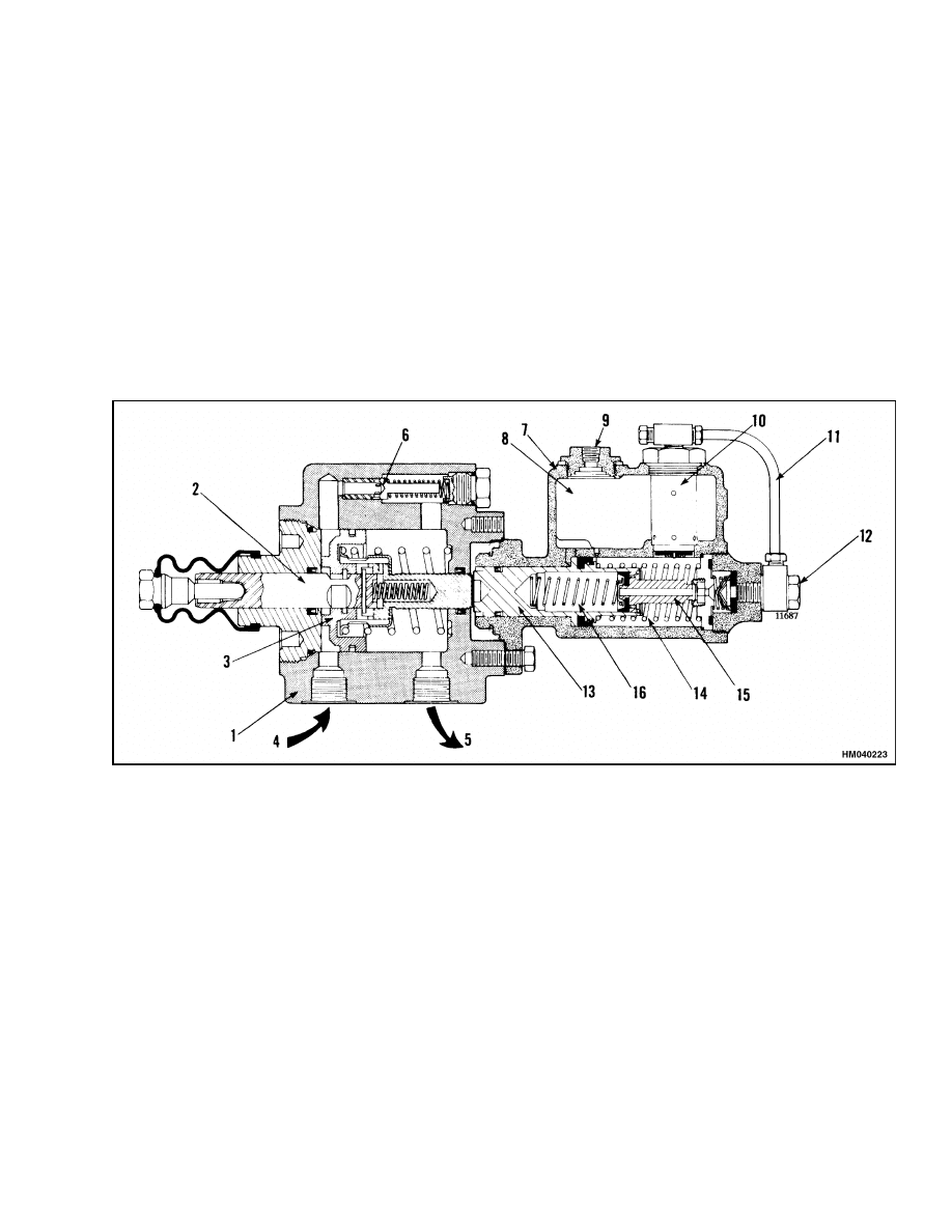
The brake system on this series of lift trucks uses
a hydraulic actuator (brake booster) to actuate the
master cylinder. See Figure 1. The operation of the
brake booster decreases the foot effort necessary to
apply the brakes. The oil flow from the outlet of
the steering control unit is used to operate the brake
booster.
The brake system consists of service brakes and the
parking brake. The service brakes have the brake
pedal, booster and master cylinder and a brake as-
sembly at each drive wheel. The parking brake has
the hand lever assembly, cables to each service brake
assembly, and a lever in the service brake assembly
to mechanically move the brake shoes.
1.
BRAKE BOOSTER
2.
PISTON ROD
3.
PISTON ASSEMBLY
4.
INLET FOR HYDRAULIC OIL
5.
OUTLET FOR HYDRAULIC OIL
6.
RELIEF VALVE (BRAKE BOOSTER)
7.
TWO-STAGE MASTER CYLINDER
8.
RESERVOIR
9.
INLET FROM RESERVE RESERVOIR
10. RELIEF VALVE (MASTER CYLINDER)
11. RELIEF VALVE TUBE
12. OUTLET TO BRAKE SYSTEM
13. LOW PRESSURE PISTON
14. LOW PRESSURE CYLINDER
15. HIGH PRESSURE PISTON
16. HIGH PRESSURE CYLINDER
Figure 1. Brake Booster and Master Cylinder
1
Operation
1800 SRM 327
Operation
The operator pushes the brake pedal to apply the
brake. This action pushes the push rod of the booster
to move the plunger. When the plunger moves, it
moves the piston. When the piston moves, it allows
the pressure from the steering pump to enter the
booster and help move the piston.
As the piston
moves, it moves the piston rod to move the piston of
the master cylinder. Brake fluid is forced through
the brake lines to the wheel cylinders.
The fluid
forces the pistons of the wheel cylinders to move the
brake shoes against the brake drums to stop the lift
truck.
When the operator releases the latch and pulls the
parking brake lever, the cables move the lever to
move the brake shoes against the brake drum to
keep the lift truck from moving.
BRAKE BOOSTER AND MASTER
CYLINDER
Brake Booster
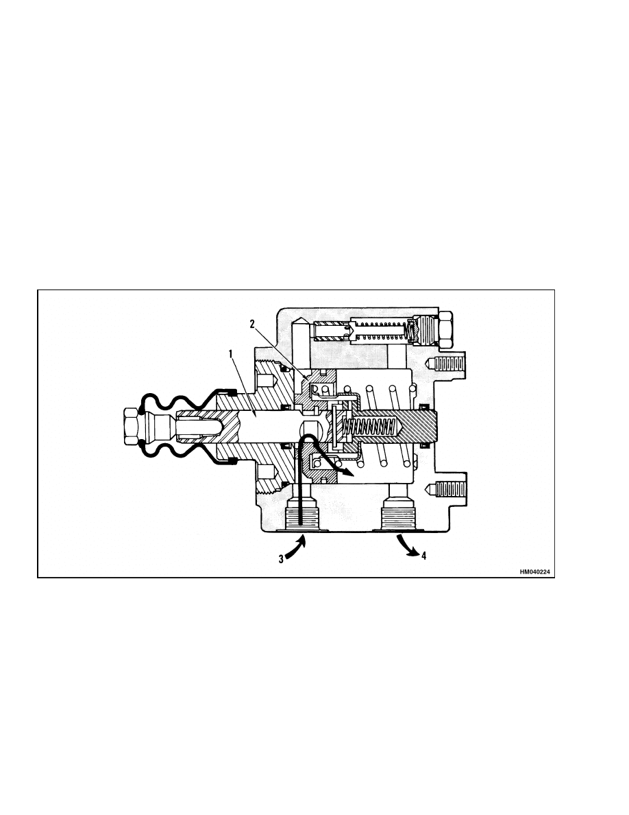
BRAKES NOT APPLIED
Hydraulic oil flows from the steering control unit to
the inlet (3) of the brake booster. The hydraulic oil
flows freely between the piston rod (1) and the piston
assembly (2) and returns to the hydraulic tank at (4).
See Figure 2.
1.
PISTON ROD
2.
PISTON ASSEMBLY
3.
OIL FLOW FROM STEERING CONTROL UNIT TO INLET
4.
OIL FLOW RETURNING TO HYDRAULIC TANK
Figure 2. Brake Booster Operation (Brakes Not Applied)
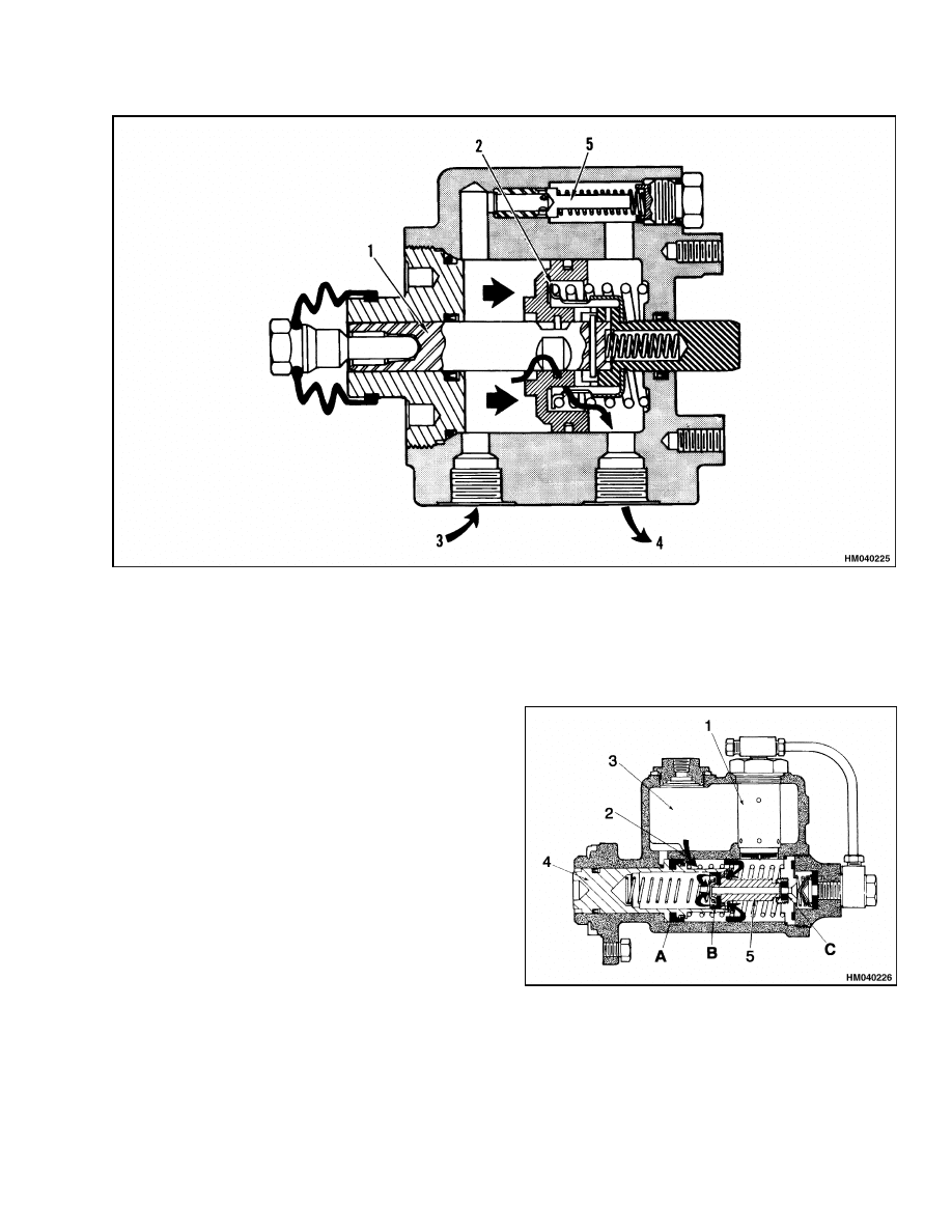
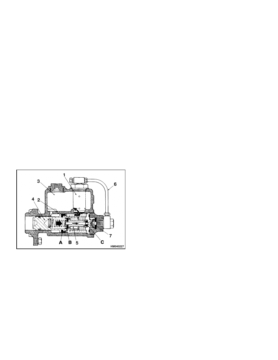
BRAKES APPLIED
The movement of the piston rod (1) causes a restric-
tion of oil flow between the rod and the piston as-
sembly (2). As the oil pressure increases, the piston
assembly moves on the shaft until the flow and pres-
sure are in balance. The movement of the piston as-
sembly actuates the master cylinder. The relief valve
(5) gives a 1205 to 1275 kPa (175 to 185 psi) limit to
the hydraulic pressure in the brake valve. See Fig-
ure 3.
2
1800 SRM 327
Operation
1.
PISTON ROD
2.
PISTON ASSEMLBY
3.
OIL FLOW FROM STEERING CONTROL UNIT TO INLET
4.
OIL FLOW RETURNING TO HYDRAULIC TANK
5.
RELIEF VALVE
Figure 3. Brake Booster Operation (Brakes Applied)
Master Cylinder
STAGE 1
When the brakes are not applied, the relief valve (1)
is closed, and the port (2) between the reservoir (3)
and the low pressure cylinder is open. When the
brakes are applied, the movement of the low pres-
sure piston (4) causes the following (see Figure 4):
a. The Cup A, on the low pressure piston, closes the
port (2). The high pressure piston (5) closes the
opening at the seal C.
b. Brake fluid moves from the low pressure cylin-
der, through the high pressure piston (5) and the
cylinder, to the brake system. The cup B, on the
high pressure piston, permits a one-way flow of
brake fluid.
c.
The low pressure and larger volume of the brake
fluid causes the brake shoes to expand against
the brake drum.
1.
RELIEF VALVE
2.
PORT
3.
RESERVOIR
4.
LOW PRESSURE PISTON
5.
HIGH PRESSURE PISTON
Figure 4. Master Cylinder Operation (Stage 1)
3
Operation
1800 SRM 327
STAGE 2
When pressure increases, it causes the following to
happen (see Figure 5):
a. The pressure in the brake system is sensed
through the relief valve tube (6). The relief valve
permits the fluid in the low pressure cylinder to
return to the reservoir at 620 kPa (90 psi).
b. The pressure difference between the high and
low pressure cylinders causes cup B to close the
ports in the high pressures piston.
c.
The high pressure piston applies a pressure to
the brake system in a ratio of the force applied
by the brake pedal and actuator.
STAGE 3
When the force of the brake pedal is released, the
brake springs retract the brake shoes and wheel
cylinders. The master cylinder returns to the begin-
ning condition. A check valve (7) keeps a pressure of
approximately 110 kPa (16 psi) in the brake system
when the brake is released.
This small pressure
keeps the brake system filled with fluid and keeps
dirt from entering the system.
1.
RELIEF VALVE
2.
PORT
3.
RESERVOIR
4.
LOW PRESSURE PISTON
5.
HIGH PRESSURE PISTON
6.
RELIEF VALVE TUBE
7.
CHECK VALVE
Figure 5. Master Cylinder Operation (Stage 2
and Stage 3)
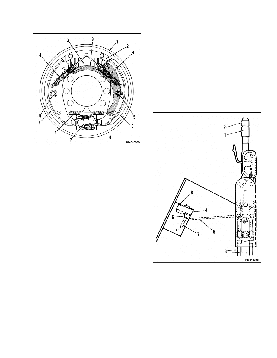
SERVICE BRAKE ASSEMBLY
A service brake assembly is used at each end of the
drive axle housing. See Figure 6. Each service brake
assembly has a wheel cylinder (3) at the top of each
back plate (1). A shoe guide (2) and guide springs (5)
keep the brake shoes (6) against the back plate. Re-
turn springs (4) hold the brake shoes tight against
the wheel cylinder and the automatic adjuster mech-
anism (7).
When the piston of the wheel cylinder is moved by
fluid pressure from the master cylinder, the piston
moves the brake shoes to contact the drum. The pri-
mary shoe starts to turn with the brake drum. This
action pushes the secondary shoe tight against the
brake drum. This servo action increases the force ap-
plied to the brake drums.
The automatic adjuster mechanism turns the ad-
juster wheels to adjust the clearance between the
brake shoes and the drum. The adjuster mechanism
operates when the lift truck is traveling in forward
or reverse. When the brakes are applied, the brake
shoes move toward the brake drum. When the bot-
tom of a brake shoe moves away from the adjuster
mechanism, the adjuster wheel moves away from
the adjuster plate. When there is clearance between
the shoe and drum, the adjuster plate can move and
engage the next tooth of the adjuster wheel. The
springs on the adjuster plate cause the adjuster
plate to rotate when the brake pressure is released.
4
1800 SRM 327
Operation
1.
BACK PLATE
2.
SHOE GUIDE
3.
WHEEL CYLINDER
4.
RETURN SPRING
5.
GUIDE SPRING
6.
BRAKE SHOE
7.
AUTOMATIC
ADJUSTER
MECHANISM
8.
BRAKE LEVER
9.
BRAKE LINK
Figure 6. Service Brake Assembly
PARKING BRAKE
The parking brake uses the service brake shoes.
See Figure 7. Additional linkage pushes the shoes
apart when the hand lever (1) pulls the cables (3).
On units with a powershift transmission and a
MONOTROL pedal, the hand lever also operates a
switch (4) that allows the key switch to energize the
starting circuit for the engine. When the parking
brake is applied, the switch de-energizes the circuit
for the MONOTROL pedal and the forward and
reverse solenoids. This action puts the transmission
in Neutral.
The starting circuit for the engine is
energized when the parking brake is applied.
1.
HAND LEVER
2.
ADJUSTMENT
KNOB
3.
CABLES TO
SERVICE BRAKES
4.
SWITCH (UNITS
WITH MONOTROL
PEDAL ONLY)
5.
LINK, SWITCH
6.
SWITCH LEVER
7.
SLOT
8.
TERMINALS
FOR NORMALLY
CLOSED (NC)
CIRCUIT
Figure 7. Parking Brake Assembly
5
Brake Shoe Assemblies Repair
1800 SRM 327
Brake Shoe Assemblies Repair
REMOVE AND DISASSEMBLE
WARNING
Brake linings can contain dangerous fibers.
Breathing the dust from these brake linings
is a cancer or lung disease hazard.
Do not
create dust!
Do not clean brake parts with
compressed air or by brushing. Use vacuum
equipment approved for brake dust or follow
the cleaning procedure in this section. When
the brake drums are removed, do not create
dust.
Do not sand, grind, chisel, hammer, or change
linings in any way that will create dust. Any
changes to brake linings must be done in a re-
stricted area with special ventilation. Protec-
tive clothing and a respirator must be used.
1.
Tilt the mast back and put blocks under the outer
mast weldments. Tilt the mast forward to raise
the tires from the floor.
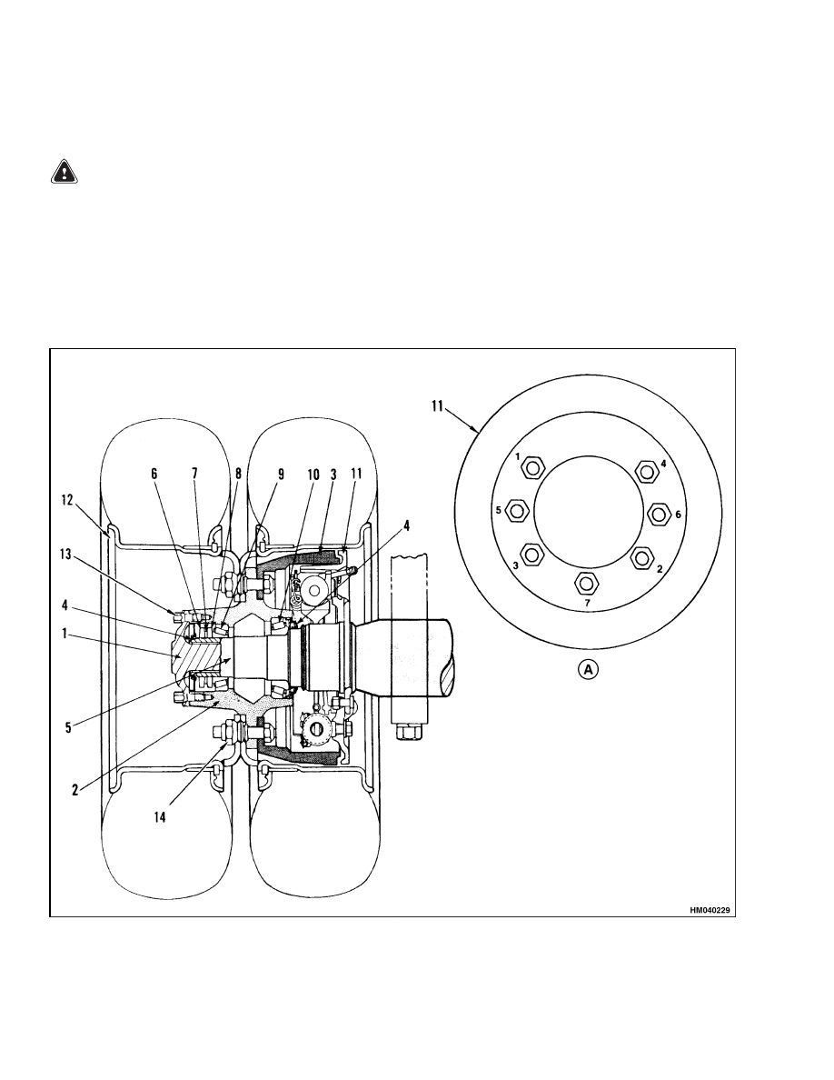
2.
The wheels, hub, and brake drum can be re-
moved as an assembly. See Figure 8.
Figure 8. Drive Axle and Brake Assembly
6

1800 SRM 327
Brake Shoe Assemblies Repair
Legend for Figure 8
A. SEQUENCE FOR BACK PLATE NUTS
1.
AXLE SHAFT
2.
HUB
3.
BRAKE DRUM
4.
SEAL
5.
AXLE HOUSING
6.
LOCK NUT
7.
LOCK PLATE
8.
ADJUSTMENT NUT
9.
BEARING, OUTER
10. BEARING, INNER
11. BACK PLATE
12. WHEEL
13. CAPSCREW
14. WHEEL NUT
3.
Remove the capscrews that hold the axle shaft to
the hub. Remove the axle shaft. See Figure 8.
4.
Remove the seal from the hub. Remove the nuts
for the bearings from the axle housing. Slide the
wheel, hub, and brake drum from the axle hous-
ing. See Figure 8.
WARNING
When the brake shoes are removed, do not cre-
ate dust in the air. See the cleaning procedures
in this section.
5.
Use spring pliers to remove the shoe return
springs. Remove the clips at the back plate for
the guide springs. Remove the guide springs.
See Figure 6.
6.
Disconnect the parking brake cable from the
parking brake lever. Remove the brake shoes.
See Figure 6.
7.
If necessary, the adjuster mechanism and wheel
cylinder can be removed from the back plate. The
back plate can be removed from the axle housing.
See Figure 6.
CLEAN AND INSPECT
WARNING
DO NOT use mineral oil solvent to clean the
master cylinder, wheel cylinder, or the brake
linings. Use a solvent approved for cleaning
brake parts. Do not permit oil or grease in the
brake fluid or on the linings.
Use alcohol to clean the master cylinder, wheel
cylinders, and the brake linings. Use solvent to
clean all of the other parts of the brake system.
WARNING
Cleaning solvents can be flammable and toxic
and can cause skin irritation.
When using
cleaning solvents, always follow the safety
instructions of the solvent manufacturer.
Observe the previous WARNINGS before cleaning.
Cleaning Procedures
1.
Do not release brake lining dust from the brake
linings into the air when the brake drum is re-
moved.
2.
Use a solvent approved for cleaning brake parts
to wet the brake lining dust. Follow the instruc-
tions and cautions of the manufacturer for the
use of the solvent. If a solvent spray is used, do
not create dust with the spray.
3.
When the dust is wet, clean the parts. Put any
cloth or towels in a plastic bag or an airtight con-
tainer while they are still wet. Put a "DANGER-
OUS FIBERS" warning label on the plastic bag
or airtight container.
4.
Any cleaning cloths that will be washed must be
cleaned so that the fibers are not released into
the air.
Inspect
1.
Check the bore of the wheel cylinder for corro-
sion, pitting, or scratches.
Replace the wheel
cylinder if there is any damage.
2.
Check the return springs for wear or damage.
Inspect the back plate for wear where the brake
shoes touch the back plate.
3.
Inspect the brake shoes for cracks or damage. If
the linings or shoes are worn or damaged, replace
the brake shoes.
WARNING
The brake shoes on both wheels must be re-
placed if any shoe is damaged, so that both
wheels have equal brake performance.
4.
Inspect the brake drum for deep grooves or other
damage on the surface for the brake shoes. Use
sandpaper to smooth the grooves on the brake
drum surface.
7
Brake Shoe Assemblies Repair
1800 SRM 327
NOTE: If the brake drums require turning on a
lathe, do not remove more than 1.5 mm (0.060 in.)
from the diameter. The maximum inside diameter
of the brake drum, including wear, is 316.82 mm
(12.473 in.).
If the diameter is larger than this,
replace the brake drum.
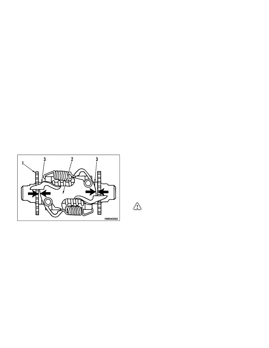
ASSEMBLE AND INSTALL
1.
Install the wheel cylinder and shoe guide on
the back plate. See Figure 6. Install the ad-
juster mechanism on the back plate.
Torque
the adjuster mounting capscrew to 175 N•m
(130 lbf ft). Use the following procedure to ad-
just the adjuster mechanism:
a. Check the clearance between the adjuster
plate and the adjuster wheels. See Figure 9.
Use shims between the adjuster wheels and
the housing until the clearance is 1.04 to
1.34 mm (0.041 to 0.053 in.). This adjust-
ment is important for the correct operation
of the automatic brake adjuster.
1.
ADJUSTER WHEEL
2.
ADJUSTER PLATE
3.
SHIMS
Figure 9. Automatic Adjuster Mechanism
NOTE:
If the lift truck does not have frequent hard
braking applications and the position of the brake
pedal is low, the brakes are not adjusting enough.
Change the shims at the adjuster wheel so that there
is a clearance of 1.50 mm (0.059 in.) at the arrows
(see Figure 9).
NOTE:
If the lift truck has frequent hard braking ap-
plications and the brakes are too tight, the brakes
are not adjusting correctly. Change the shims at the
adjuster wheel, so there is a clearance of 1.80 mm
(0.071 in.) at the arrows (see Figure 9).
NOTE:
Use the inspection hole in the back plate
and check the clearance between the brake drum
and brake shoe. The correct clearance is 0.94 mm
(0.037 in.) maximum.
2.
Install the back plate on the axle housing. Install
the tapered sleeves and the nuts. Tighten the
nuts in the cross pattern to 55 to 80 N•m (41 to
59 lbf ft), then tighten the nuts in the same cross
pattern to 110 to 125 N•m (81 to 92 lbf ft).
3.
Install the lever for the parking brake on the
brake shoe. See Figure 6. Install the brake shoe.
Install the parking brake link. Connect the park-
ing brake cable to the lever.
4.
Install the guide springs and install the clips on
the back of the brake plate. Install the shoe re-
turn springs. See Figure 6.
5.
If removed, install the hub, brake drum, and
wheels on the hub. See Figure 8. Tighten the
nuts for the brake drum and wheels to 610 to
680 N•m (450 to 500 lbf ft).
6.
Lubricate the inner wheel bearing with grease,
then install the inner seal in the hub. See Fig-
ure 8.
7.
Slide the wheel and hub assembly on the axle
housing. Lubricate the outer wheel bearing with
grease and install the bearing on the axle hous-
ing. See Figure 8.
CAUTION
Do not damage the seal when installing the
wheel and hub assembly.
8.
Install the bearing adjusting nut. See Figure 8.
Tighten the nut to 200 N•m (150 lbf ft) while
turning the hub. Loosen the nut to less than
27 N•m (20 lbf ft). Tighten the nut to 35 N•m
(26 lbf ft). Lock the adjusting nut at this position
or tighten the nut to the first position where the
lock plate fits. Install the lock nut and tighten it
to 135 N•m (100 lbf ft).
9.
Use a sealant on the flange of the oil seal and
install the outer seal in the hub. See Figure 8.
Use a sealant on the flange of the axle shaft and
install the axle shaft. Tighten the capscrews to
165 N•m (122 lbf ft). Check the differential oil
level and fill as described in the section, Peri-
odic Maintenance 8000 SRM 341.
8
1800 SRM 327
Master Cylinder Repair
10. Fill the brake reservoir, remove the air from the
brake system, and adjust the brakes as specified
in Brake System Air Removal and Brake Shoes
Adjustment in this section.
Master Cylinder Repair
NOTE: It is recommended that when the master
cylinder is repaired or replaced, replace the piston
ring in the brake booster as shown in Figure 12.
REMOVE
1.
Disconnect the brake line at the master cylinder.
Cover the end of the brake line. Disconnect the
wires at the brake switch. Disconnect the hose
from the reservoir. Put a plug in the end of the
hose.
2.
Remove the capscrews that hold the master
cylinder to the brake booster.
DISASSEMBLE
CAUTION
Use a cleaning fluid made for brake parts when
cleaning the master cylinder.
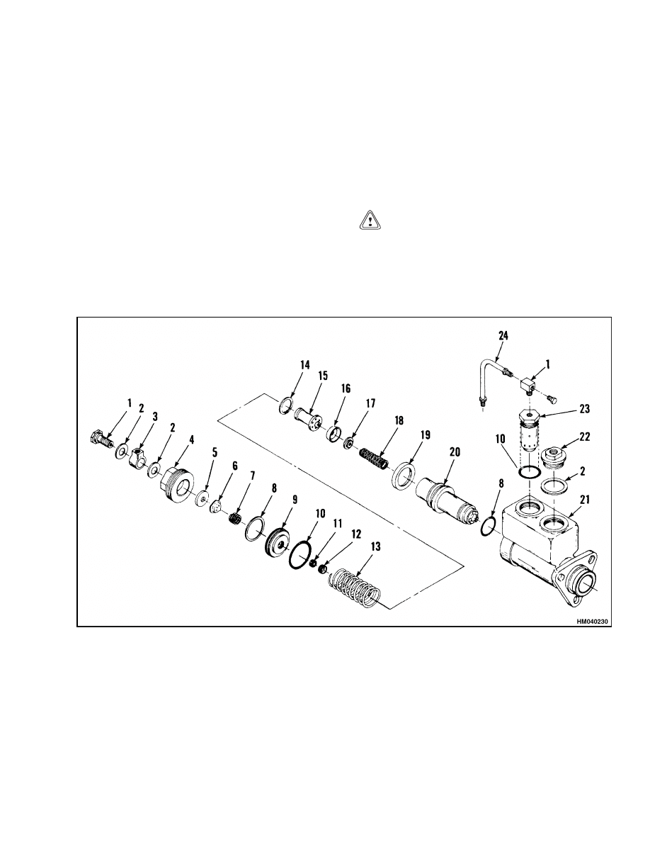
1.
Loosen the relief valve tube. See Figure 10. Re-
move the adapter and gaskets. Remove the relief
tube.
1.
LINE ADAPTER
2.
GASKET
3.
FITTING
4.
PLUG
5.
VALVE SEAT
6.
CHECK VALVE
7.
CHECK VALVE SPRING
8.
SEAL
9.
RETAINER
10. O-RING
11. SEAL
12. RETAINER
13. SPRING
14. RETAINER RING
15. PISTON, HIGH PRESSURE
16. CUP SEAL
17. SPRING RETAINER
18. SPRING
19. SEAL
20. PISTON, LOW PRESSURE
21. BODY
22. FILL PLUG
23. RELIEF VALVE
24. TUBE
Figure 10. Master Cylinder
9
Master Cylinder Repair
1800 SRM 327
WARNING
The plug has a compressed spring behind it.
Remove the plug carefully. Make sure to hold
the spring in position so that it cannot cause
damage or injury to someone.
2.
Remove the plug. Remove the check valve assem-
bly, retainer, and spring.
3.
The retainer will come out of the bore when the
plug is removed. Remove the seal and O-ring.
Remove the retainer and the seal from the re-
tainer.
NOTE:
The tip of the relief valve extends into the
cylinder bore when installed.
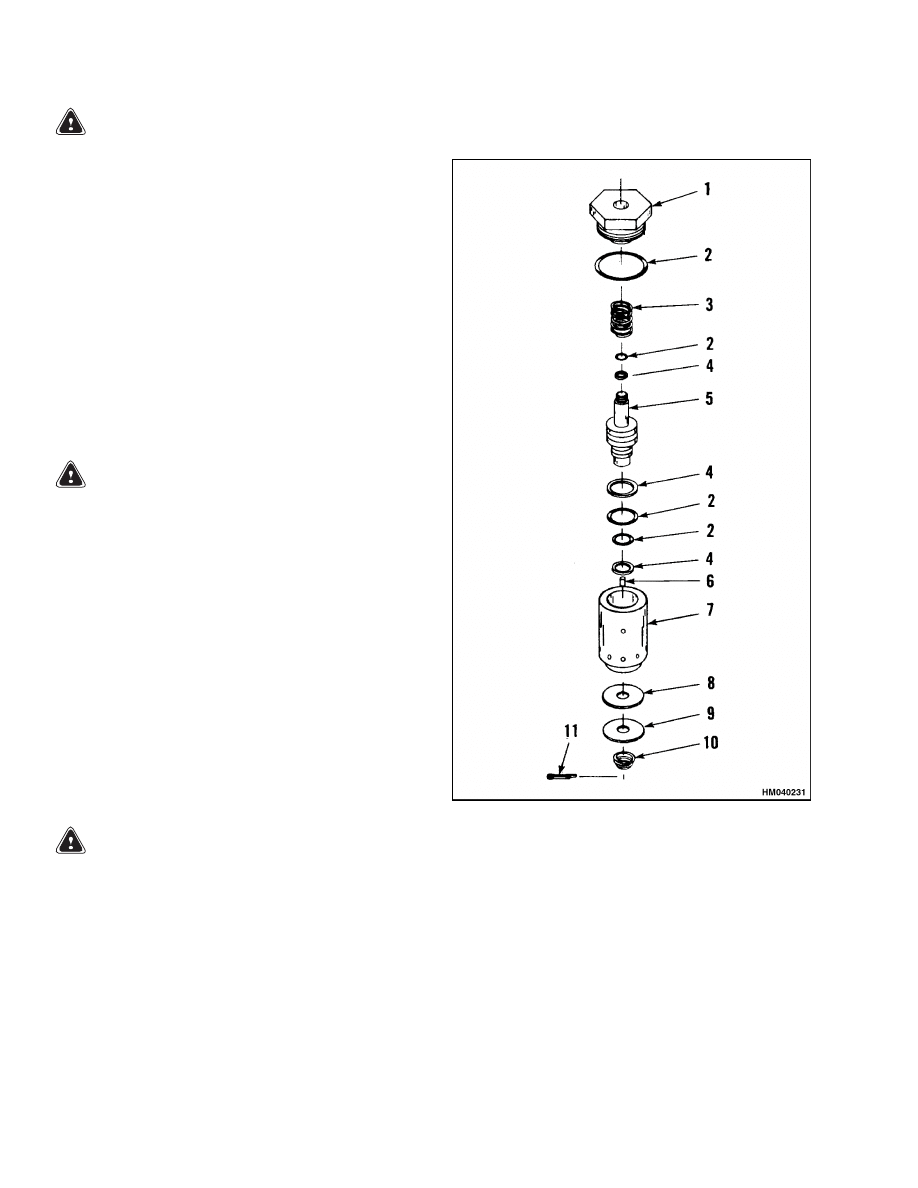
4.
Remove and disassemble the relief valve assem-
bly as follows (see Figure 11):
WARNING
The plug has a compressed spring behind it.
See Figure 11.
Remove the plug carefully.
Make sure to hold the spring in position so it
cannot cause damage or injury.
a. Remove the plug and the O-ring. Remove the
relief valve spring.
b. Lift the relief valve assembly from the cham-
ber in the reservoir.
c.
Remove the piston assembly from the valve
body. Pull and rotate the piston from the
valve body. Do not lose the metering pin.
d. Remove the cotter pin, seal washer, and
spring from the valve body.
5.
Remove the piston assembly from the valve body.
WARNING
The high pressure piston has a compressed
spring behind it. See Figure 10. Remove the
piston carefully. Make sure to hold the spring
in position so that it cannot cause damage or
injury.
6.
Push the high pressure piston into its bore and
remove the retaining ring. See Figure 10. Re-
move the high pressure piston and the spring
from the bore. Remove the cup seal from the pis-
ton.
1.
PLUG
2.
O-RING
3.
SPRING
4.
BACKUP RING
5.
PISTON
6.
METERING PIN
7.
VALVE BODY
8.
SEAL
9.
WASHER
10. SPRING
11. COTTER PIN
Figure 11. Relief Valve Assembly
10

1800 SRM 327
Brake Booster Repair
ASSEMBLE
NOTE:
Lubricate the parts of the master cylinder
with clean brake fluid.
1.
Install the retainer on the small end of the
spring. See Figure 10. Install the spring in the
low pressure piston.
2.
Install the cup seal on the high pressure piston.
3.
Put the high pressure piston and the cup seal
in position against the retainer. Carefully push
the high pressure piston into the bore of the low
pressure piston. Install the retaining ring.
4.
Install the seal and retainer in the retainer.
5.
Install the seals on the low pressure piston. In-
stall the piston assembly into the bore of the mas-
ter cylinder.
6.
Install the spring in the bore of the master cylin-
der. Install the check valve seat, check valve, and
valve spring in the plug.
7.
Install the O-ring and seal on the retainer. In-
stall the retainer into the bore of the master
cylinder. Install the plug and check valve assem-
bly against the retainer. Turn the plug into the
master cylinder. Tighten the plug.
8.
Assemble and install the relief valve assembly as
follows (see Figure 11):
a. Make sure all of the parts are clean. Use new
parts from the repair kit.
b. Install the cotter pin, seal, washer, and
spring in the bottom of the valve body.
c.
Put the metering pin in the orifice at the bot-
tom of the valve body.
d. Assemble the O-rings and backup rings on
the piston. Lubricate the piston with J-1703
brake fluid. Install the piston assembly in
the valve body.
e.
Install the spring, O-ring, and plug for the
relief valve.
9.
Install the two gaskets and the line adapter on
the master cylinder. Install the line adapter on
the plug for the relief valve. Tighten the fittings
for the relief valve tube. Install the fill plug and
gasket.
INSTALL
1.
Put the master cylinder in position on the brake
booster and install the capscrews for the master
cylinder.
2.
Connect the brake lines and wires. Connect the
hose to the brake fluid reservoir. Fill the reser-
voir and remove the air from the brake system as
described in Brake System Air Removal in this
section.
Brake Booster Repair
REMOVE
1.
Remove the floor plates. Clean the area around
the brake line and hydraulic line connections.
See Figure 1.
2.
Disconnect the brake pedal from the brake
booster at the push rod.
3.
Disconnect the hydraulic lines at the brake
booster. Put caps on the open lines.
4.
Disconnect the brake lines and wires at the mas-
ter cylinder (7). Disconnect the hose from the
reservoir at the master cylinder. Put a plug in
the end of the hose.
5.
Remove the capscrews that hold the brake
booster (1) to the bracket.
Remove the brake
booster and master cylinder as an assembly.
DISASSEMBLE
1.
Remove the master cylinder from the brake
booster.
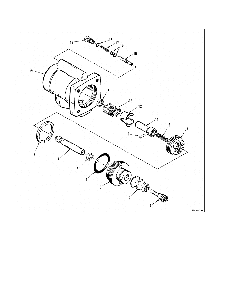
2.
Remove the dust cover (2) and push rod (1). See
Figure 12.
11
Brake Booster Repair
1800 SRM 327
1.
PUSH ROD
2.
DUST COVER
3.
PLUG
4.
O-RING
5.
SEAL
6.
PISTON ROD
7.
PISTON RING
8.
PISTON
9.
SPRING
10. PIN
11. PISTON PLUNGER
12. RETAINER
13. SPRING
14. HOUSING
15. VALVE STEM
16. SHIMS
17. SPRING
18. O-RING
19. PLUG
Figure 12. Brake Booster
12

1800 SRM 327
Brake System Air Removal
WARNING
The threaded plug (3) has a compressed spring
(13) behind it. Make sure to hold the spring
in position so that it cannot cause damage or
injury to someone.
3.
Carefully remove the threaded plug (3). Remove
the retainer and piston assembly. Remove the
piston and spring retainer.
4.
Push on the piston rod and remove the pin that
holds the piston rod in the piston plunger. Re-
move the piston rod and spring.
5.
Remove the relief valve assembly from the hous-
ing.
CLEAN AND INSPECT
Clean the parts of the brake booster with solvent.
Check the surface of the machined parts for wear and
damage.
ASSEMBLE
NOTE: Use new parts from the repair kit. Lubricate
the parts with hydraulic oil during assembly. Make
sure the parts are clean.
CAUTION
Do not let brake fluid touch any of the parts of
the brake booster. The brake fluid can damage
the seals in the brake booster.
1.
Assemble the parts for the relief valve. Make
sure all of parts are in their original positions.
2.
Install the seals in the retainer and the housing.
3.
Install the spring (13) and piston rod in the pis-
ton plunger. Install the pin that holds the piston
rod in the piston plunger. See Figure 12.
4.
Install the piston ring on the piston. Install the
piston on the piston rod. Install the spring re-
tainer and the spring on the piston assembly.
5.
Install the piston assembly in the housing. In-
stall the dust cover and push rod on the retainer.
INSTALL
1.
Install the master cylinder on the brake booster.
Install the brake booster on the bracket.
2.
Connect the hydraulic lines to the brake booster.
Connect the brake lines and wires to the master
cylinder. Connect the hose from the reservoir to
the master cylinder.
3.
Connect the push rod to the crank and the brake
pedal. Install the pin for the push rod.
4.
Remove the air from the brake system and adjust
the brake linkage as described in Brake System
Air Removal in this section.
Brake System Air Removal
The air must be removed from the brake fluid. Fill
the reservoir of the master cylinder with brake fluid.
Put one end of a rubber hose on the special fitting of
the wheel cylinder. Put the other end of the hose in a
container with brake fluid. Loosen the special fitting.
Push slowly on the brake pedal. Close the fitting at
the wheel cylinder. Repeat the procedure until no air
bubbles are seen in the container. Check the fluid
level in the master cylinder. Keep the master cylin-
der full of brake fluid during these procedures. Use
the procedures described for the wheel cylinders to
remove air from the relief tube at the master cylin-
der. Use the fitting at the line connector on the relief
valve.
13
Brake Pedal Adjustment
1800 SRM 327
Brake Pedal Adjustment
NOTE:
The adjustment procedures for the inching
pedal are in the section, Two-Speed Powershift
Transmission, Repairs 1300 SRM 325.
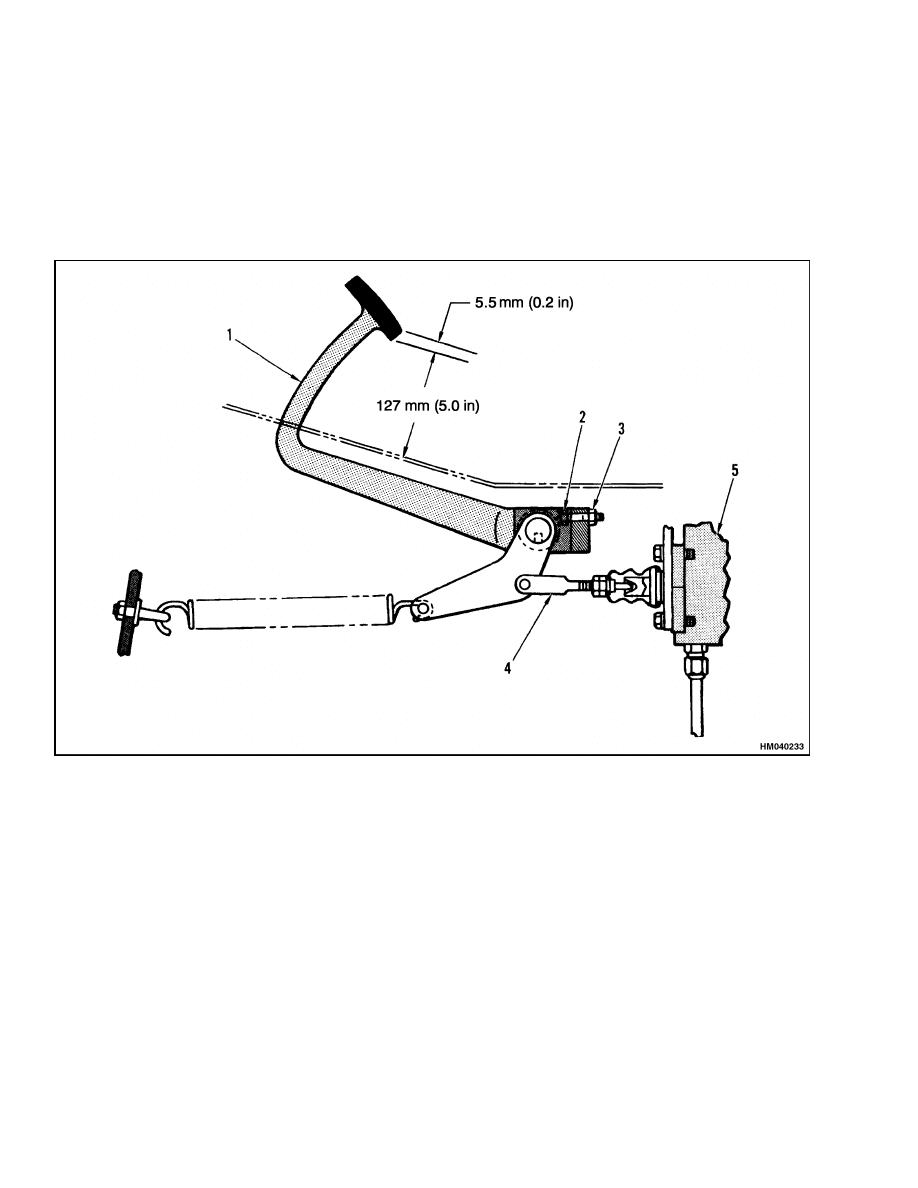
1.
Adjust the height of the brake pedal above the
floor plate as shown in Figure 13. Use the stop
screw and nut behind the pedal to adjust the
height.
2.
Adjust the push rod for the brake booster so that
there is 5.5 mm (0.2 in.) of free travel in the brake
pedal.
1.
BRAKE PEDAL
2.
STOP SCREW
3.
NUT
4.
PUSH ROD
5.
BRAKE BOOSTER
Figure 13. Brake Pedal Adjustment
14

1800 SRM 327
Brake Booster Relief Valve Check
Brake Shoes Adjustment
The brake shoes will adjust automatically by apply-
ing the brake pedal while traveling in forward or re-
verse. To manually adjust the brakes, it is neces-
sary to turn the adjuster wheels. Remove the rub-
ber plugs in the adjustment slots in the backplate.
Put a small screwdriver through the slot in the back-
plate. Make sure to install the plugs after the ad-
justment is complete. See Figure 9. Push the ad-
juster plate away from the adjuster wheel and turn
the adjuster wheel until the brake shoe just touches
the brake drum. Adjust the brake shoes for the other
wheel using the same method. Remove the blocks
and operate the lift truck in the forward and reverse
directions. Make 10 stops in each direction using the
brakes. This action will adjust the brakes automati-
cally.
NOTE: If the lift truck does not have frequent hard
braking applications and the position of the brake
pedal is low, the brakes are not adjusting enough.
Change the shims at the adjuster wheel so that there
is a clearance of 0.94 mm (0.037 in.) at the arrows.
See Figure 9.
NOTE: If the lift truck has frequent hard braking
applications and the brakes are too tight, the brakes
are not adjusting correctly. Change the shims at the
adjuster wheel so that there is a clearance of 1.40 mm
(0.055 in.) at the arrows. See Figure 9.
Parking Brake Adjustment
Turn the knob on the hand lever to adjust the park-
ing brake. The brake must hold the lift truck with a
capacity load on a 15% grade. See Figure 7.
If the lift truck has a powershift transmission and
a MONOTROL pedal, make sure the switch is actu-
ated by the handle lever when the parking brake is
applied.
Parking Brake Switch Adjustment
1.
Apply the parking brake. See Figure 7. The link
must be at the maximum limit of travel (top of
slot). If the link is not in this position with the
parking brake applied, check that the normally
closed (NC) circuit of the switch is opened when
the switch lever is actuated by the link. The NC
circuit goes through the two terminals at the end
of the switch.
2.
If the switch is open with the brake lever applied,
the installation is correct. If the circuit remains
closed with the brake lever applied, the link for
the switch has been bent and must be replaced.
3.
When the new link is installed, check again to
make sure the normally closed (NC) circuit of the
switch is opened when the parking brake lever is
applied.
Brake Booster Relief Valve Check
The relief valve is adjusted at the factory and is not
normally adjustable. Shims can be added or removed
between the spring and the valve stem. The correct
relief pressure is 1205 to 1275 kPa (175 to 185 psi).
See Figure 12.
15

Troubleshooting
1800 SRM 327
Troubleshooting
PROBLEM
POSSIBLE CAUSE
PROCEDURE OR ACTION
The brakes do not operate
equally.
Oil or brake fluid is on the linings.
Repair leak. Install new linings.
The linings are worn or hard.
Install new linings.
A wheel cylinder is leaking.
Repair or install new wheel cylinder.
Remove air from the system.
The brake linings are not correctly
installed.
Install brake linings correctly.
The back plate or brake shoes are
damaged.
Install new parts.
A brake drum is damaged or not
round.
Check to make sure there is adequate
material to allow for machining. Ma-
chine the brake shoe area to make
them round or install new drums.
One brake assembly does not
release.
The shoes are adjusted too tightly.
Adjust brakes.
The back plate or brake shoes are
damaged.
Install new parts.
The brake lines have a restriction.
Install new brake lines.
A cable for the parking brake is dam-
aged.
Install new cable.
Both brakes do not release.
The parking brake is not released.
Release parking brake.
The parking brake cables need ad-
justment.
Adjust or install new cables.
There is not enough clearance at the
end of the push rod in the master
cylinder.
Adjust the clearance between the
push rod and the piston.
The master cylinder is damaged.
Install new master cylinder. Remove
air from the system.
16

1800 SRM 327
Troubleshooting
PROBLEM
POSSIBLE CAUSE
PROCEDURE OR ACTION
The pedal is hard to push.
The pedal linkage is damaged.
Repair linkage.
The linings are worn.
Install new linings.
Water or oil is on the linings.
Clean or install new linings.
The master cylinder is damaged.
Repair or install new master cylin-
der. Remove air from the system.
The brake booster has a malfunction.
Repair or install new brake booster.
The brake booster has a malfunc-
tion. The seals in the brake booster
are damaged.
Install new seals.
The brakes make noise.
Dirt is on the linings.
Clean or install new linings.
The linings are worn.
Install new linings.
A brake drum is damaged.
Install a new brake drum.
The brake pedal travels too
far.
Air in the brake system.
Remove air from the system. Check
for leaks.
Brake fluid level low. The brake sys-
tem has a leak.
Fill brake fluid reservoir to the cor-
rect level. Repair leak. Remove air
from the system.
The brake shoes are not adjusted cor-
rectly.
Check operation of automatic ad-
justers. Adjust brakes.
The brake linings are worn.
Install new linings.
The linings do not fit the drum.
Adjust the linings.
A wheel cylinder is leaking.
Repair or install new wheel cylinder.
Remove air from the system.
The master cylinder is worn or dam-
aged.
Repair or install new master cylin-
der. Remove air from the system.
The pedal return spring is broken.
Install new spring.
17

Troubleshooting
1800 SRM 327
PROBLEM
POSSIBLE CAUSE
PROCEDURE OR ACTION
The brakes do not stop the
lift truck.
Oil, water, or brake fluid is on the lin-
ings.
Clean or install new linings.
The linings are worn.
Install new linings.
The wheel cylinders are leaking.
Repair or install new wheel cylinder.
Remove air from the system.
The shoes are not adjusted correctly.
Adjust brakes.
The master cylinder is worn or dam-
aged.
Repair or install new master cylin-
der. Remove air from the system.
The brake booster does not operate
correctly.
Repair or install a new brake booster.
The parking brake will not
hold the lift truck.
Parking brake not adjusted correctly.
Use adjustment knob on parking
brake lever to adjust holding force.
See adjustment procedure for correct
specifications.
The shoes are not adjusted.
Adjust brakes.
The linkage for brake shoes is dam-
aged or not connected.
Repair linkage.
Oil, water, or brake fluid is on the lin-
ings.
Clean or install new brake linings.
The parking brake cables need ad-
justment, lubrication, or have dam-
age.
Install new parts. Lubricate and ad-
just cables.
The parking brake will not
release.
The parking brake lever is adjusted
too tightly.
Adjust parking brake.
See adjust-
ment procedure for correct specifica-
tions.
The parking brake cables need ad-
justment, lubrication, or have dam-
age.
Install new parts. Lubricate and ad-
just cables.
18


TECHNICAL PUBLICATIONS
1800 SRM 327
9/03 (3/97)(5/86) Printed in United Kingdom
Document Outline
- toc
- Brake System
- Safety Precautions Maintenance and Repair
- General
- Description
- Operation
- Brake Shoe Assemblies Repair
- Master Cylinder Repair
- Brake Booster Repair
- Brake System Air Removal
- Brake Pedal Adjustment
- Brake Shoes Adjustment
- Parking Brake Adjustment
- Parking Brake Switch Adjustment
- Brake Booster Relief Valve Check
- Troubleshooting
Wyszukiwarka
Podobne podstrony:
więcej podobnych podstron