
SPRAY FORMING OF HIGH-ALLOYED TOOL
STEELS TO BILLETS OF MEDIUM SIZE DIMENSIONS
A. Schulz
Stiftung Institut f¨ur Werkstofftechnik, Werkstofftechnik, Badgasteiner Str. 3,
D-28359 Bremen,
Germany
V. Uhlenwinkel
Stiftung Institut f¨ur Werkstofftechnik, Verfahrenstechnik, Badgasteiner Str. 3,
D-28359 Bremen,
Germany
C. Bertrand
SIDENOR I+D S.A., Barrio Ugarte s/n, Apartado 152,
E-48970 Basauri, Vizcaya,
Spain
R. Kohlmann
Krupp Edelstahlprofile GmbH, TQ-SQ, Postfach 10 12 20,
D-57012 Siegen,
Germany
A. Kulmburg
TU Graz, Inst. F. Werkstoffkunde, Schweisstechnik u. Spanlose Formgebungsverfahren,Prangelgasse
12A,
A-8020 Graz,
Austria
1125

1126
6TH INTERNATIONAL TOOLING CONFERENCE
A. Oldewurtel
D¨orrenberg Edelstahl GmbH R¨underoth, Hammerweg 7,
D-51776 Engelskirchen,
Germany
R. Schneider
B¨ohler Edelstahl GmbH & Co KG, EFE, Mariazellerstr. 25,
A-8605 Kapfenberg,
Austria
D. Viale
Usinor Industeel S.A., Centre de Recherche des Mat´eriaux du Creusot, 56, rue Clemenceau,
F-71202 Le Creusot Cedex,
France
Abstract
In the last 20 years spray forming has been developed for materials production
by combining the benefits of the high solidification rates in powder metallurgy
processes with the high production rates usually achieved in casting. From
a thermodynamical point of view it encompasses the whole process from the
melt to the solid material in one step. The as-sprayed material quality depends
on the process parameters, the production scale, the size and the shape of the
final product. A medium size spray-forming plant with a melt capacity of
150 kg steel and production rates of 15 kg per minute has been used. Through
a stable process with stationary thermal conditions for several minutes, billets
of about 200 mm diameter and 500 mm length have been spray formed.
The primary microstructure of high alloyed tool steel billets (X40CrMoV5-
1, X153CrMoV12, HS6-5-2C) has been investigated by means of metallog-
raphy and electron-beam metallography. The chemical composition of the
billets has been studied, as well as the carbide distribution and microsegrega-
tion. All were fine and homogeneously distributed. Nitrogen pick-up from
the process gas was suppressed by using argon for the melting atmosphere.
Porosity of the materials was low. Depending on alloy composition either
porous rim or internal cracks must be avoided to allow further processing
without serious problems. To compare the material properties of as-sprayed
material with conventionally produced high quality steels of similar grade a
full density needs to be achieved through hot working.

Spray Forming of High-Alloyed Tool Steels to Billets of Medium Size Dimensions
1127
Keywords:
Spray forming, cold work steel, hot work steel, high-speed steel, microstruc-
ture, nitrogen
INTRODUCTION
The spray forming process has been investigated during the last decades
in different fields of research. It has found a niche in areas where cast al-
loys were difficult to produce, e.g. for nickel-base alloys, hypereutectic
aluminium-silicon alloys, copper-base alloys and many others. The main
benefits of this technique are based on the rapid solidification in a spray of
liquid, semi-liquid and solidified droplets, which leads to a primary struc-
ture without macrosegregation. Additionally free-standing shapes can be
produced by manipulating the relative movement of the deposit to the spray
cone. Overviews are given by Leatham, [1] and Gill, [2].
From an economical point of view the spray forming of steels only makes
sense for the commercial production of complex alloys, because of the highly
optimised production for conventional steels. Igharo and Wood investigated
M2 high-speed steel spray formed by Osprey Metals Ltd. [3]. The as-sprayed
material was very dense and without skeleton-like eutectic M
6
C carbides.
In comparison to gas-atomised high-speed steel powders where MC is the
major carbide type the microstructure of spray formed 50 kg billets show
discontinuous networks of M
2
C and fine spherical MC [5]. Heavy hot-
working of spray formed tool steel is usually necessary to lower the high
porosity, and this strongly influences the carbide size distribution. Then, for
example, the spray formed S11-2-5-8 shows a higher wear resistance than
obtained from P/M-quality ASP30 [4].
Heat treatment of spray formed high-speed steel M2 gives similar sec-
ondary hardening in comparison to conventional material, but also a higher
peak hardness. This is explained by an additional dispersion hardening pro-
cess [6]. During spray forming, and under certain conditions, M
2
C-carbides
precipitate in spray formed tool steels at the grain boundaries [7]. These
carbides decompose to MC and M
6
C during 1 h heating at about 1200℃,
leading to higher bending strength.
End mills have also been manufactured from spray formed high-speed
steels. These end mills show a higher microhardness in comparison to com-
petitive P/M quality steel, but the Charpy impact values were low, which is
consistent with theory. During cutting of stainless steel and tool steel the
spray formed mills show good performance [8].

1128
6TH INTERNATIONAL TOOLING CONFERENCE
A comparison of differently produced tool steel materials including, spray
formed material, was done by Guglielmi et al. After hot working and heat
treatment the cast, P/M, and spray formed T15 steels have similar hardness.
The fracture toughness for the spray formed material was in between the
others. Large differences in wear resistance and cutting properties of the
three materials were not observed [9].
Shaw and Spiegelhauer presented the spray formed cold-work steel D2,
an alloy with high chromium and carbon contents [10]. An absence of
macrosegregation and a fine microstructure composed of fine martensite
islands surrounded by white carbides with a grain size of 30 to 80 µm was
found. The material showed satisfactory impact toughness properties and
excellent forgeability. After forging the material has a fine microstructure
without trails of large blocky carbides, as can be seen in cast and forged
material, nearly approaching that of P/M products with service performance
equivalent to conventional products [11, 12].
The concept for the spray forming process for the industrial scale pro-
duction of special steel billets was shown by Overgaard et al. [13]. The
horizontal arrangement of the billets during formation gave the scope of a
continuous production. Even though the actual production rates of spray
formed tool steels are low, the spray forming technique of special high al-
loyed steels is competitive with the P/M technology [14].
In the present study the intention is to spray form tool steels on a medium
size plant and find out the peculiarities of the technique used here with respect
to the properties of the as-sprayed materials. Furthermore, enough material
shall be produced within one experiment to give the possibility of subsequent
hot-working and machining to a semi-finished product of sufficient amount.
The final objective is the comparative study of materials of the spray forming
route with conventionally produced material and P/M- material. The results
of this study will be presented in a second paper during this conference.
EXPERIMENTAL
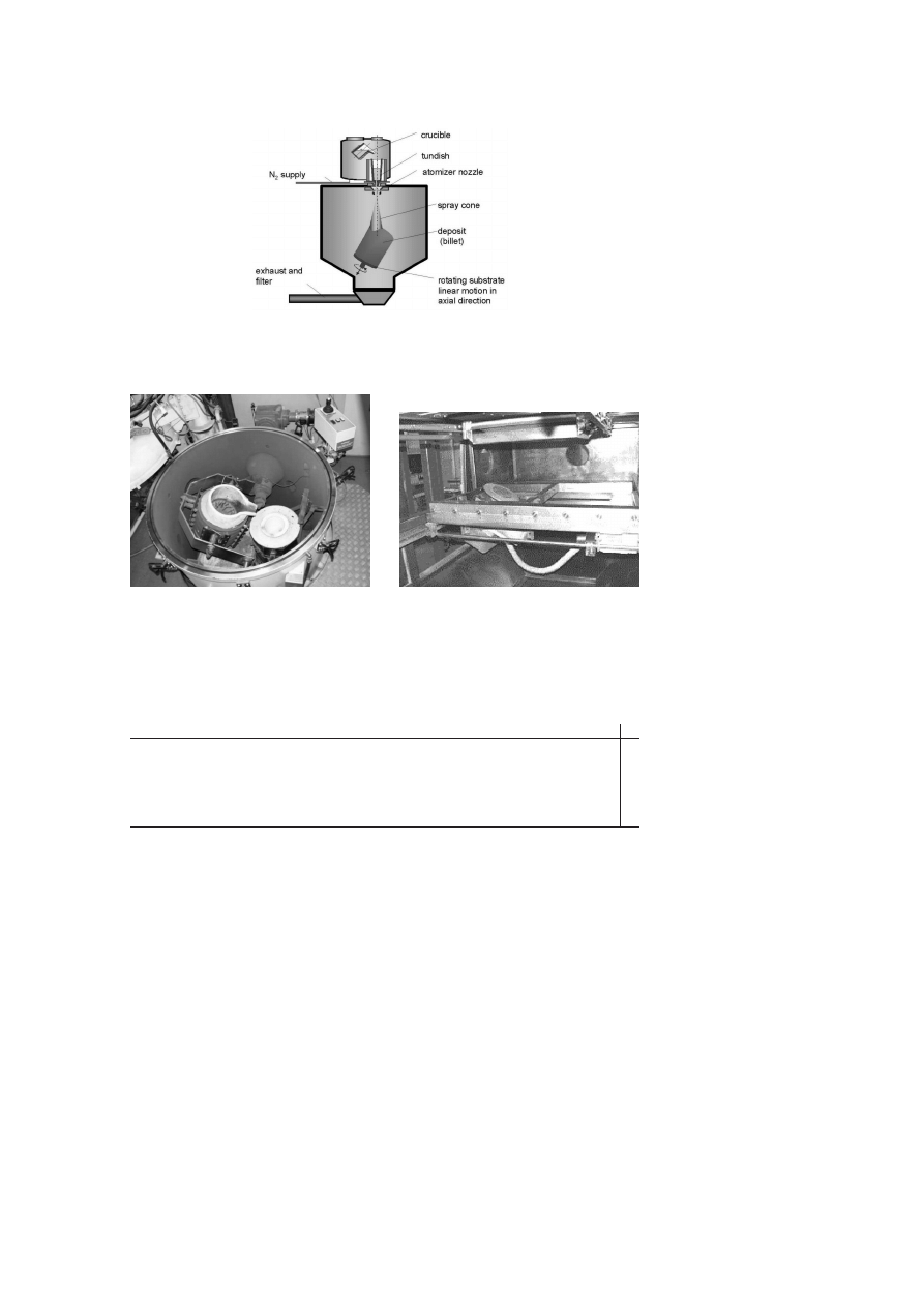
For the production of spray formed materials on a technological scale,
a plant with a capacity of 150 kg liquid steel is used (Fig. 1a). Melting is
done under a protective atmosphere of either 1 bar nitrogen or argon. The
manually driven and visually controlled pouring system (Fig. 1b) supplies
a tundish up to a constant melt level to achieve a constant flow of about
1000 kg/h. A scanning free-fall atomizer is used for the disintegration of

Spray Forming of High-Alloyed Tool Steels to Billets of Medium Size Dimensions
1129
the melt stream flowing through the outlet at the bottom of a tundish. The
tundish and the outlet are made of refractory material. Nitrogen was used
as the atomization gas for the experiments. The substrate, which is rotating
under a defined angle with respect to the spray cone, moves downwards
along the rotating axis synchronously to the growing deposit by means of a
computer controlled three-axis-stage (Fig. 1c), while keeping the spraying
distance constant at 500 mm. A second important parameter, the gas to metal
mass ratio (GMR), during atomization has to be taken into account. For the
experiments it is usually kept constant at GMR = 1, but was varied between
0.5 and 1.5 to influence spray cone properties, like mean particle diameter,
mean particle speed, liquid fraction of droplets and heat transfer from the
billet surface.
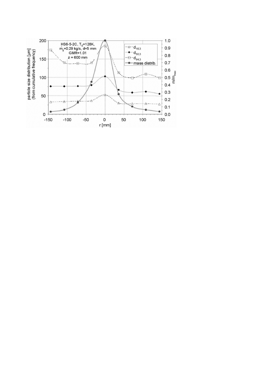
The mass flux of the spray cone is mainly focused on a round area with a
diameter of about 50 mm at 500 mm spraying distance and through a spray
cone angle of 5.7° (Fig. 2). The sprayed particles have a mass median
diameter of 60 to 70 µm with a slight increase at the centre. But even at the
cone axis more than 85% of the particles are smaller than 200 µm.
Conventionally produced steel rods of 55 mm in diameter were used as
the feed material for the remelting process. The compositions are listed in
Table 1. Most of the work focuses on the standard cold working, hot working
and high-speed steels. Additional experiments have been carried out with
numerous steel qualities.
The investigation of spray formed billets focusing on porosity is mainly
done by a volumetric method (DIN EN6018), and supported by digital im-
age analysis. Chemical composition is analysed by OES (optical emission
spectroscopy) and PDA-OES (pulse discriminating analysis). Carbon- and
nitrogen analysis is carried out by the combustion technique (N/O and C/S
determination). For metallographic preparation standard methods are ap-
plied and nital is used as etchant. Electron microprobe analysis is used for
carbide analysis.
RESULTS
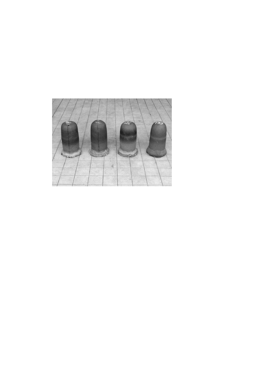
Despite the relative small dimensions of the plant it is necessary to achieve
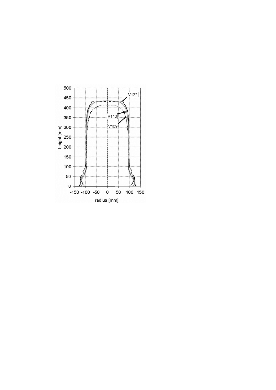
a stable process with good reproducibility (Fig. 3). This is given for the billet
diameter and for the total shape for a material from the batches one by one
and over longer periods (Fig. 4). The "elephant’s foot" contains the substrate
plate (∅
200 × 10). The diameter reduction at the billet’s head results from
1130
6TH INTERNATIONAL TOOLING CONFERENCE
Figure 1a.
Sketch of the medium-scale spray forming plant.
Figure 1b.
Closed vessel with 150 kg
steel melt crucible and tundish.
Figure 1c.
3-axis stage with rotating sub-
strate ∅ 200 mm, inclination 30
°.
Table 1.
Alloy composition, wt%
C
Si
Mn
P
S
Cr
Mo
V
W
Co
Al
Ni
N
Creq
C105
1.02
0.29
0.18 0.004 0.015
–
–
–
–
–
–
–
0.007
-2.7
100Cr6
0.85
0.3
0.3
0.02 0.012
1.5
–
–
–
–
–
–
0.004
-0.7
C15
0.16
0.17
0.55 0.008 0.027
–
–
–
–
–
0.021
–
0.006
-0.3
X40CrMoV5-1
0.41
0.98
0.36
0.01 0.002 4.98
1.36
0.99
0.00
–
0.02
0.15 0.011
5.6
HS6-5- 2C
0.92
0.35
0.26 0.022 0.0005 3.77
4.78
1.74
6.07
0.57 0.009 0.15 0.031
6.3
X153CrMoV12
1.54
0.34
0.26
0.02 0.004 11.7
0.75
0.94
0.15
–
0.029
0.3
0.024
9.8
X10CrAlSi25
0.1
1.2
0.38
0.02
23.4
0.02
0.04
0.01
–
1.22
0.2
0.05
21.5
Spray Forming of High-Alloyed Tool Steels to Billets of Medium Size Dimensions
1131
Figure 2.
Mass distribution in the spray cone
instationary process conditions after the end of pouring from the crucible
to the tundish. While running empty the level of melt in the tundish and
therefore the melt mass flow decreases slowly. Conditions are constant for
about 80% of the 10 minute process. Billets of 200 mm diameter and a length
of 300 to 400 mm, representing masses of 75 to 95 kg, can be formed.
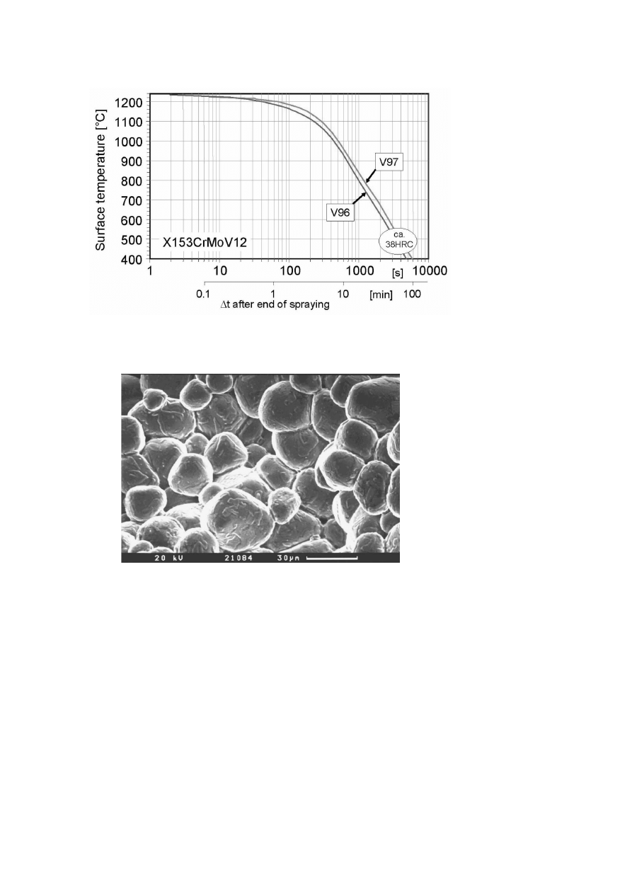
A second indication for process reproducibility is the surface temperature
of the deposits. After the spray stops the head of the billet cools down from
a value slightly above the solidus temperature to 400℃ by free convection
and radiation in about 90 minutes. The variation between batches is less
than 20 K (Fig. 5).
Especially for the X153CrMoV12 the rapid cooling (app. 0.5 K/s in the
first few minutes after the production process has finished) of the deposits
frequently leads to a defect in the head of the billet located about 100 mm
below the tip, as is detected by ultrasonic inspection. This defect becomes
visible after the deposit is cut. In the scanning electron microscope (Fig. 6)
of the void, globular grains of about 30 µm diameter are visible at the fracture
surface, where EDX shows high chromium concentration in a surface layer,

1132
6TH INTERNATIONAL TOOLING CONFERENCE
which indicates that a film of residual melt solidified after the void opened,
indicating a so called "type 1" hot crack (with a liquid phase involved).
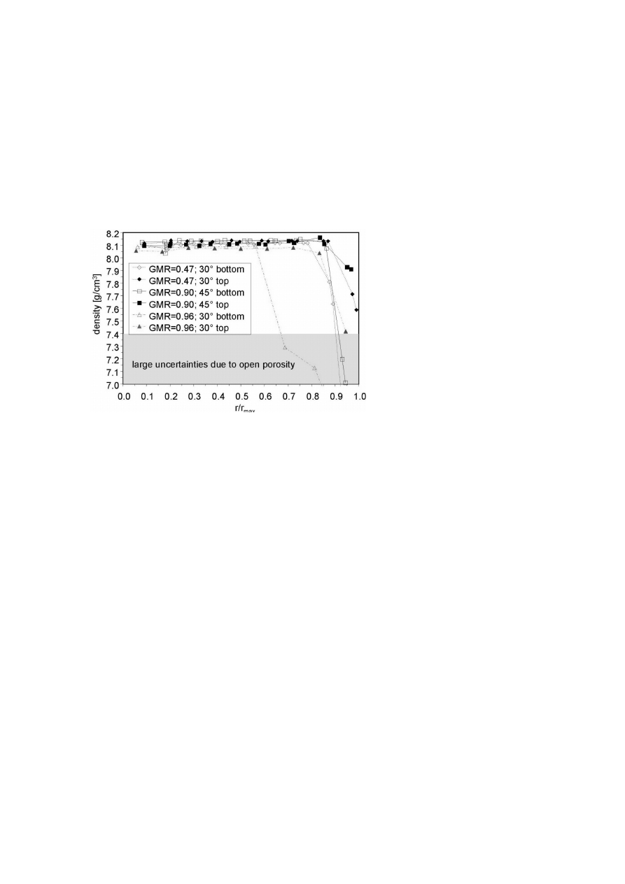
Density of the billets is generally high in the centre and a porous area
is found at the rim, reducing the usable volume (Fig. 7). Both geometry
(substrate inclination angle) and spray cone properties (GMR) can be used
to minimize centre porosity and porous rim. Under optimised conditions
more than 80% of the billet is processable for forging (this will be even
more for larger billet diameters), based on the stringent assumption that the
minimal density of material usable for hot working is 1% below the average
density inside the billet or 1.5 to 2% below theoretical density. At this point
of optimisation there is hardly any porosity visible (density of HS6-5-2C
stock material is (8.12 ± 0.01) g/cm
3
).
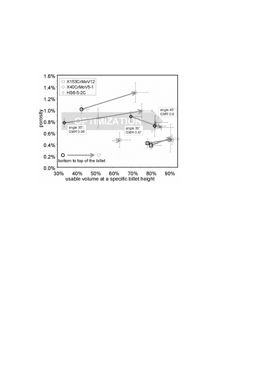
Comparing the three steels X153CrMoV12, HS6-5-2C and X40CrMoV5-
1 it can be clearly seen that porosity and usable volume depend on the alloy
composition (Fig. 8). With increasing carbon content, the porosity decreases
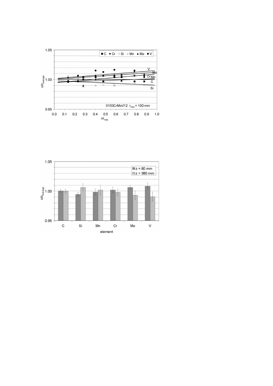
and the porous rim becomes smaller. Macroscopic gradients in chemical
composition are not detectable inside the billets, neither in the radial nor the
axial direction (Figs. 9 and 10). A detailed investigation of macrosegregation
has been carried out by PDA-OES, but over fields of 2000 mm
2
no gradients
are visible. Some changes in the average alloy composition are caused by
the spray forming process despite the fact that the process is running under an
argon protective atmosphere during melting and pouring. The reduction of
carbon of about 0.01 to 0.07 wt% increases with the initial carbon contents of
the alloy. The variation of heavy alloying elements is very small compared
to the level of concentration in the alloys.
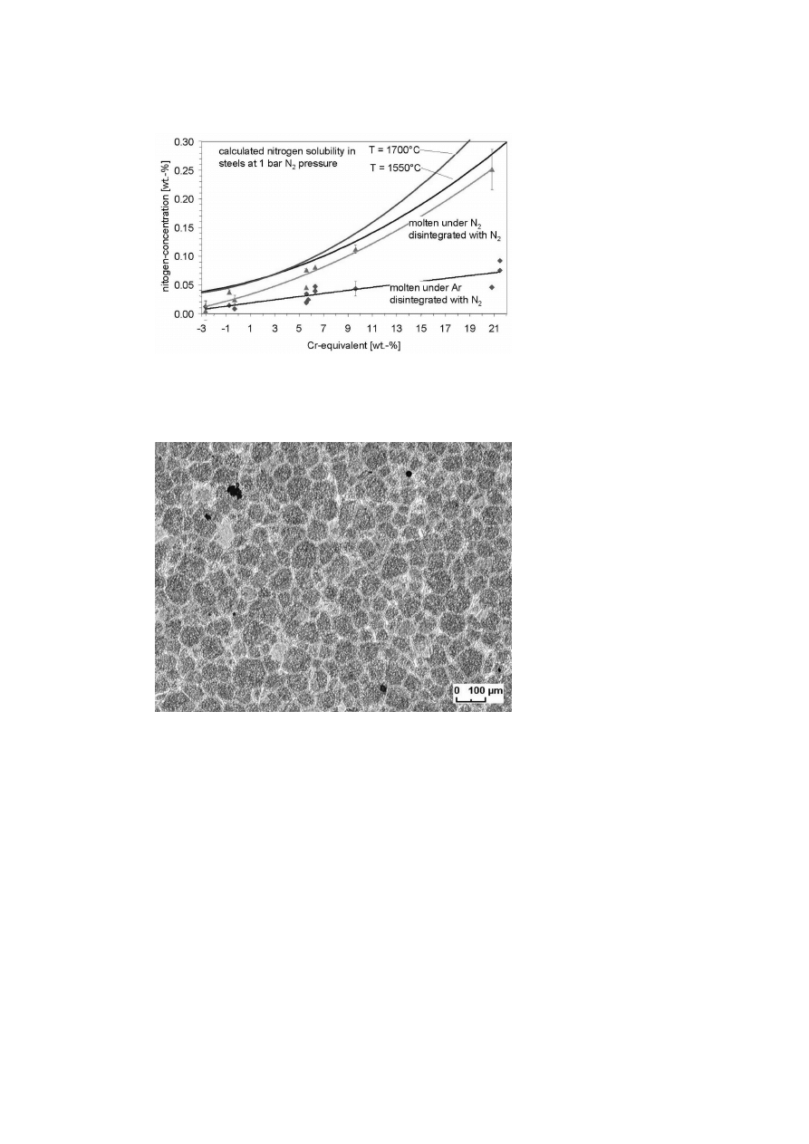
The plot of the nitrogen concentration in the billets versus the chromium
equivalent (equation (1)) [15] of the alloys shows a strong increase of nitro-
gen concentration with increasing Cr
eq
when melting, pouring, atomizing
and depositing in a nitrogen atmosphere (Fig. 11). By protecting the melt
with argon during melting and pouring most of the nitrogen entrapping is
avoided.
C r
eq
= −2.46[C] − 0.9[Si] + 0.5[Mn] − [P ] + [Cr] + 0.27[Mo]
−0.22[N i] + 2.05[V ] + 0.04[W ]0.12[Cu]
−0.2[Co] + 19.4[T i] + 1.05[N b] − 0.85[Al]
(1)
C r
eq
= Chromium equivalent of the alloy in wt%;
[x] = Concentration of the element x in wt%

Spray Forming of High-Alloyed Tool Steels to Billets of Medium Size Dimensions
1133
The graph includes the solubility limit [16] at a nitrogen pressure of 1 bar,
for the steels where the melting before spray forming usually happens. This
barrier is not exceeded during the spray forming process, but the nitrogen
concentrations in the steels produced completely under nitrogen atmosphere
are close to these values.
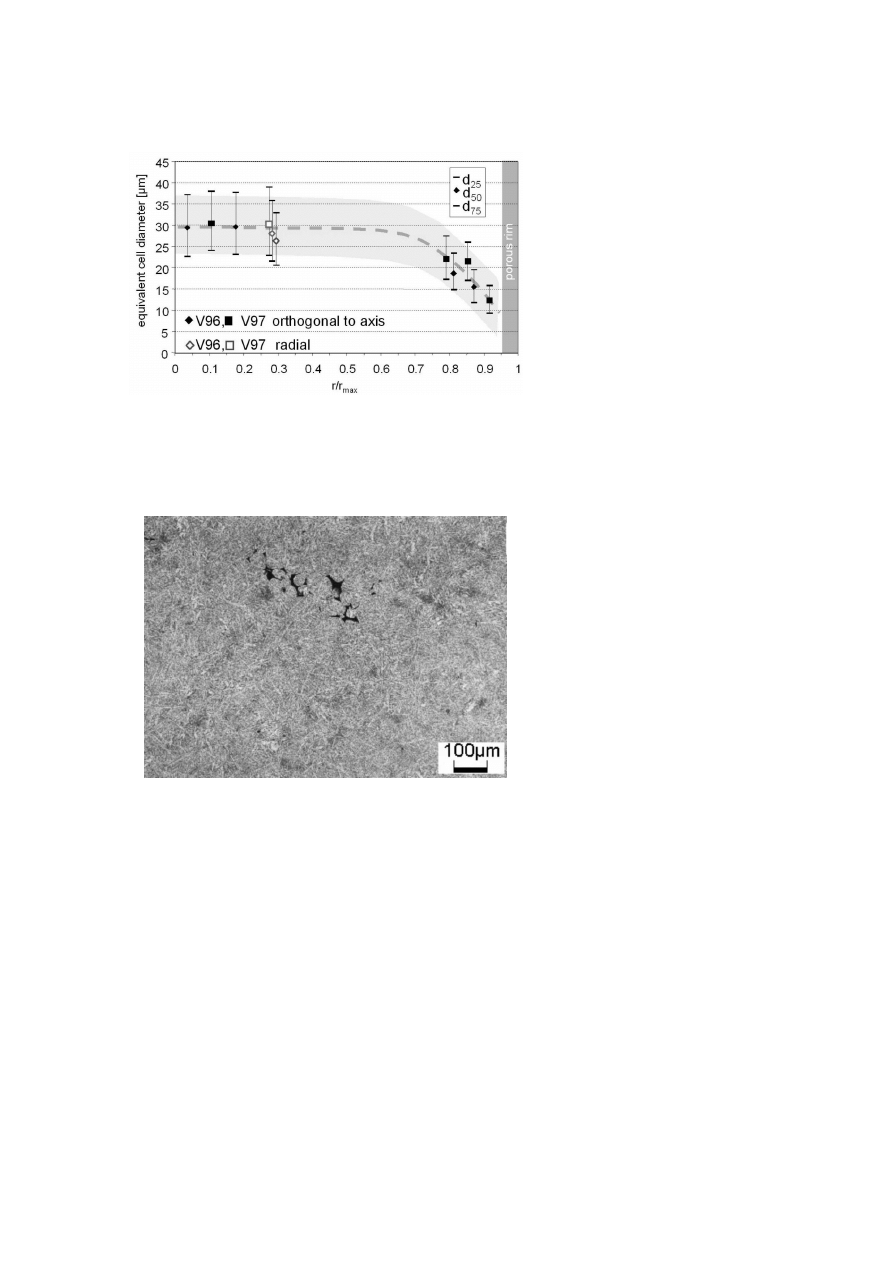
The microstructure of the ledeburitic tool steels after spray forming and
subsequent annealing consists of a very fine and homogeneously distributed
carbide network, as shown for the cold-working steel (Fig. 12). Eutectic
carbide structures ("fishbone") are very few and far between. The size of
the ledeburitic cells has been investigated by means of image analysis and
determined at 30 microns inside the billets with a close variance and and
a further reduction towards the rim of the billets (Fig. 13). There is an
enormous number of more than 1100 cells per cm
2
over most of the usable
billet diameter. Significant differences in cell size of X153CrMoV12 and
HS6-5-2C were not found.
Carbide analysis of the high alloyed steels generally shows no extraor-
dinary results. The X153CrMoV12 has coarse (Cr,Fe,V,Mo)
7
C
3
carbides
between the grains of α-Fe with fine globular carbides, but also some coarse
intragranular carbides of the same type. For the HS6-5-2C two carbide types
[(Fe,W, Mo)
6
C, and (V,W,Mo)C] were found between the matrix grains. In-
tragranular carbides of MC type were also observed. They appear to be
rich in Vanadium, but are too small to be completely analysed by means of
microprobe analysis.
For the hot-working steel X40CrMoV5-1 with lower carbon contents and
less alloying elements the microstructure shows no larger carbides but is
very evenly distributed. The lower density is caused by locally concentrated
voids, where the spray is not completely compacted (Fig. 14). Carbides
are too fine to be analysed by means of X-ray diffraction or microprobe
analysis, but there is evidence for both M
2
C and MC carbides being located
intergranularly as well as intragranularly.
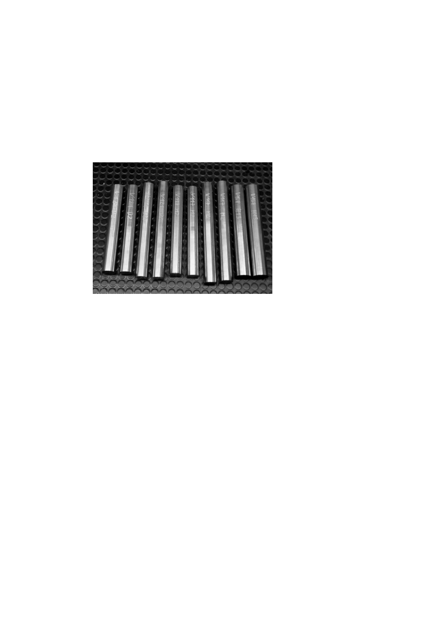
All three tool steels are die forged at 1120℃ to rods of 65 mm diam-
eter after scrubbing 10 mm from the surface, respectively 15 mm for the
X40CrMoV5-1 with an average total reduction of area of 6.25 to 7.25 in a
sequence of six heating and forging cycles and are finally machined to round
bars of 60 mm diameter (Fig. 15).

1134
6TH INTERNATIONAL TOOLING CONFERENCE
DISCUSSION
Spray forming starts with a large superheated and inductively stirred melt
that is slowly poured into a tundish. This results in a strong interaction of
the melt with the surrounding atmosphere. When using nitrogen as the pro-
tective atmosphere the nitrogen concentration of the melt is increased to the
solubility limit of the specific alloy. During atomization the nitrogen pick-up
is much lower despite the high melt surface area (approximate surface area
1.5 m
2
per gram of melt). The major reason for this is that the particle flight
time from the atomisation point to the deposit surface is less than 10 ms,
furthermore the small droplets are rapidly cooled and solidified. Therefore
during atomisation and compaction time is too short and temperature too low
for intensive pick-up of nitrogen. Most nitrogen pick-up of the final prod-
uct can be suppressed by using argon as the protective atmosphere during
melting.
The atomisation and interaction with the gas leads to a large loss of en-
thalpy during the particle flight time. Despite the short process time the
billet is rapidly cooled and therefore only a small volume at the surface has
a temperature between solidus and liquidus. Loss of heat by radiation and
convection to the environment and conduction to the already compacted and
cooled deposit together with input of hot (liquid) droplets and cold parti-
cles keep this "mix-layer" dynamically constant. Furthermore the mix-layer
is not homogenous but is expected to show thermal gradients [18]. The
cooling rate of the droplets during the flight is approximately 10
4
K/s, this
rate decreases below 10 K/s in the deposited material where solidification is
finished. The resulting solidification time in the deposit is used for consoli-
dation, e.g. the filling of voids between particles and feeding local shrinkage
voids, but the remaining solidification time can also be used for diffusion
that may cause microsegregation.
This context becomes clear by comparing the different solidification ranges
of the three tool steels. For X153CrMoV12 and HS6-5-2C the solidifica-
tion ranges are quite similar at about 185K and 225K, respectively. For
X40CrMoV5-1 it is about 70K, i.e. only about one third of time for complete
solidification inside the mixed layer, thus resulting in higher bulk porosity.
The time span for passing through the solidification range is even shorter
at the outer rim of the billet, when the particle and enthalpy flux slowly is
reduced when leaving the spray cone in the direction of billet withdraw. The

Spray Forming of High-Alloyed Tool Steels to Billets of Medium Size Dimensions
1135
higher solidus temperature (about 200K) of the hot working steel compared
to the two higher alloyed steels leads to a higher loss of heat by radiation,
and the higher thermal conductivity enhances heat flux into the already cold
areas of the deposit reducing the time span for solidification. This explains
the reduced usable volume that is achieved for the hot working steel.
Another characteristic of the process is that spray formed billets cool
slowly while growing, but rapidly after the spray cone stops. This can lead
to a hot spot in the head of the billet on the axis in a region at the base
of the hemispherical head of the billet [19]. In the case of large amounts
of low melting eutectics with wide solidification ranges, there can be too
much residual liquid inside this area. Contraction during further cooling
leads to a large void. The voids inner surface (Fig. 6) consists of globular
grains surrounded by a film of former residual melt with a high chromium
concentration. This property is especially evident in X153CrMoV12 and can
cause type 1 hot cracks to form. Fortunately the void is easy to detect and
the region can be separated before further processing. For HS6-5-2C there is
intermittent hot cracking. Only additional equipment or handling to achieve
reduction of stress peaks shortly after end of spraying might overcome this
problem. While this is already solved for large billet production there is still
work necessary for the billet size presented here.
The grain size visible in Fig. 6 is similar to the cell size of 30 µm measured
by image analysis (Fig. 13). This value is less than half the mean droplet
size, thus indicating that the microstructure results from a rapid solidification.
Therefore despite the hot spot no further grain growth happens. Only at the
rim of the billets does the higher cooling rate lead to significantly smaller
cells (Fig. 13). Most of this area has to be machined because the larger
porosity connected to the higher cooling rate will cause serious problems
during subsequent forging.
Nevertheless, because of the homogenous and step by step solidification
of the billet out of a homogeneously stirred melt no macroscopic gradients in
materials composition are detectable. The carbide composition does not dif-
fer from the expected composition for the alloys. Only the small size causes
some problems during analysis by electron beam metallography, where the
probe of a few microns in diameter is of similar size as the microstructural
parts.
The process atmosphere can explain the small changes in the alloy compo-
sition. Despite working under protective gas conditions a residual oxygen

1136
6TH INTERNATIONAL TOOLING CONFERENCE
partial pressure is present, and because of the large melt surface after at-
omization at high temperatures some oxydation of carbon can occur. On
the other hand at this time there is enough nitrogen present to cause some
dissolution. Nevertheless the nitrogen entrapment which occurs during com-
paction at the billet surface can not be assumed to be negligible, a fact that
is frequently discussed in literature [20].
Nitrogen pick-up up during atomization can be avoided by using argon
as the atomizing gas despite its high cost. Entrapment of argon in the billet,
which cannot be dissolved when closing the pores by hot working might
lead to ultrafine voids with highly pressurised gas inside which may cause
problems in the final product.
CONCLUSION
Spray forming of high alloyed tool steels in a medium size plant leads
to a material product with a homogeneously distributed microstructure and
chemical composition. This homogeneity together with the low bulk poros-
ity requires only little hot working to achieve homogenous material of full
density.
Even for the steels, where the risk of a void in the billet head is high
and requires non- destructive inspection two third of the billet length can
be used, and therefore about 60 kg material can be produced from one run.
This is still sufficient material for numerous materials tests and a small series
of components for use in application-oriented tests. Industry requires larger
billets of approximately 4000 kg with similar properties for commercial pro-
duction [14]. The medium size equipment presented here can not meet these
demands but can be utilised to develop and test modified alloys.
On the other hand the small unit can be used to develop extreme niche
products otherwise only producible by powder metallurgical methods.
ACKNOWLEDGMENTS
The working group would like to acknowledge the European Commis-
sion for funding the ECSC programme research project 7210PR-173 and
the Collaborative Reseach Centre SFB 372 at the University of Bremen,
funded by the Deutsche Forschungsgemeinschaft for making avaiable the
spray forming plant.

Spray Forming of High-Alloyed Tool Steels to Billets of Medium Size Dimensions
1137
REFERENCES
[1] A. LEATHAM; Materials Word, June (1996), p. 317–320.
[2] T. GILL; Metal Bulletin Monthly, (1996) 2, p. 50–53.
[3] M. IGHARO, J. V. WOOD; Powder Met. 32 (1989) 2, p. 124–131.
[4] B. HRIBERNIK, H. P. FAULAND, G. HACKL, B. KRISZT; In: Proc. ICSF 90–27.01
(1990).
[5] E.-S. LEE, W.-J. PARK, J. Y. JUNG, S. AHN; Mater. Trans. 29A (1998), p. 1395–1404.
[6] T. KIRBY, M. IGHARO, J. V. WOOD, R. PRATZ; In: Proc. 1st Intern. Conf. on Spray
Forming, Swansea, UK, 17–19 September 1990.
[7] K.-H. BAIK, E.-S. LEE, W.-J. PARK, S. AHN; In: Proc. 3rd Intern. Conf. on Spray
Forming (1996), p. 251–256.
[8] E. YABUUCHI, Y. KUROSHIMA, M. MASUDA, M. KUBOBUTI, Y. IKAWA; In-
tern. J. of the Japan. Soc. for Precision Engineering, 27 (1993) 4, p. 327–332.
[9] F. GUGLIELMI, G. BEVOLO; In: Proc. 1st Intern. Conf. on Spray Forming, 1990.
[10] L. H. SHAW, C. SPIEGELHAUER; In: Proc. 3rd Int. Conf. on Spray Forming, Cardiff,
UK (1996), p. 101–113.
[11] C. SPIEGELHAUER, L. SHAW; In: Proc. 1996 World Congress on Powder Metal-
lurgy & Particulate Materials, June 16-21, Washington, D.C. Compiled by: T. Cadle,
S. Narasimhin; 3 (1996), p. 9–91.
[12] C. SPIEGELHAUER; In: 5th Intern. Tooling Conf.; Eds.: F.Jeglitsch, R.Ebner, H.
Leitner, 29.9.- 1.10.1999, Leoben, Austria, University of Leoben (1999), p. 249–254.
[13] J. OVERGAARD, T. ANDERSEN, K. SCHWARZ; Technical Steel Research, Volume
EUR 15593 (1996), Luxembourg
[14] C. SPIEGELHAUER; Steel World 5 (2001) 1, p. 30–32.
[15] A. H. SATIR-KOLORZ, H. K. FEICHTINGER; Z. Metallkde. 82(1991)9; p. 689-697
[16] B. I. MEDOVAR, V. Y. SAENKO, G. M. GRIGORENKO, Y. M. POMARIN,
V. I. KUMYSH; Cambridge Internat. Sci. Publ. 1996, p. 47.
[17] S. SPANGEL, A. SCHULZ, H. VETTERS, P. MAYR; In: Proc. Int. Conf. on Spray
Deposition and Melt Atomisation, 26.-28.6.2000, Bremen, Germany. Ed. by. K. Bauck-
hage et. al, Vol. 1; Universität Bremen 2000, p. 109–120.
[18] K. BAUCKHAGE, D. BERGMANN, J. TILLWICK, Kolloquium des SFB 372, Vol.
4, Universität Bremen 1999, p. 139–171.
[19] V. UHLENWINKEL, J. FISCHER, R. SCHR ¨
ODER, A. SCHULZ, K. BAUCKHAGE;
In: Proc. Conf. PM2TEC’99, 20.-24.6.1999, Vancouver, B. C., Canada; Vol. 2, Pt. 4;
Comp. by C.L. Rose and M.H.Thibodeau; MPIF, Princeton, N.J. 1999, p. 4-235 –
4-245
[20] C. Y. A. TSAO, N. J. GRANT; Mater. Sci. Engin. A201 (1995), p.261–268.
1138
6TH INTERNATIONAL TOOLING CONFERENCE
Figure 3.
Spray formed tool steel billets (about 95 kg) (X40CrMoV5-1; X153CrMoV12).
Spray Forming of High-Alloyed Tool Steels to Billets of Medium Size Dimensions
1139
Figure 4.
Reproducibility of billet diameter (X40CrMoV5-1).
1140
6TH INTERNATIONAL TOOLING CONFERENCE
Figure 5.
Surface temperature of X153CrMoV12 billets after end of spraying (repro-
ducibility of two batches).
Figure 6.
Scanning electron image of the inner surface of the void in the head of a
X153CrMoV12 billet.
Spray Forming of High-Alloyed Tool Steels to Billets of Medium Size Dimensions
1141
Figure 7.
Density distribution in HS6-5-2C at two levels inside the billets (60 mm from
the foot and 70 mm from the tip) at different states of optimization.
1142
6TH INTERNATIONAL TOOLING CONFERENCE
Figure 8.
Porosity and porous rim of spray formed tool steel billets (for HS6-5-2C a
process optimisation was carried out (substrate angle; GMR, s. Fig. 7), otherwise standard
parameters (30
°; 0.96) are used).
Spray Forming of High-Alloyed Tool Steels to Billets of Medium Size Dimensions
1143
Figure 9.
Radial deviation from average concentration of elements in a spray formed
X153CrMoV12 billet.
Figure 10.
Axial deviation from average concentration of elements in a spray formed
X153CrMoV12 billet.
1144
6TH INTERNATIONAL TOOLING CONFERENCE
Figure 11.
Nitrogen concentration vs. chromium equivalent.
Figure 12.
Microstructure of a spray formed and annealed X153CrMoV12 billet.
Spray Forming of High-Alloyed Tool Steels to Billets of Medium Size Dimensions
1145
Figure 13.
Equivalent cell diameter in X153CrMoV12 billets vs. sample position (d50 =
median; d25, d75 include 25% and 75% of grains).
Figure 14.
Microstructure of X40CrMoV5-1 (spray formed and annealed).
1146
6TH INTERNATIONAL TOOLING CONFERENCE
Figure 15.
Round bars manufactured from the X153CrMoV12, HS6-5-2C and
X40CrMoV5-1 billets.
Wyszukiwarka
Podobne podstrony:
78 1101 1109 Industrial Production of Tool Steels Using Spray Forming Technology
81 1147 1158 New Generation of Tool Steels Made by Spray Forming
79 1111 1124 The Performance of Spray Formed Tool Steels in Comparison to Conventional
29 387 402 HSS Produced by Conventional Casting, Spray Forming and PM
82 1159 1179 Advanced Tool Steels Produced via Spray Forming
39 533 547 Carbide Dissolution Rate and Carbide Contents in High Alloyed Steels
16 197 208 Material Behaviour of Powder Metall Tool Steels in Tensile
21 269 287 Effect of Niobium and Vanadium as an Alloying Elements in Tool Steels
20 255 268 Influence of Nitrogen Alloying on Galling Properties of PM Tool Steels
36 495 507 Unit Cell Models for Thermomechanical Behaviour of Tool Steels
1 3 16 Comparison of Different Characteristics of Modern Hot Work Tool Steels
więcej podobnych podstron