The Model Engineer
A Journal of Small Power Engineering.
Edited by Percival Marshall. C.1.Mech.E.
V
O L
. XLVIII. No. 1,141. MARCH 8, 1923. PUBLISHBD WEEKLY.
Our Point of View.
Speed
Boats of 1922.
The following officially recorded speeds of
boats entered in the M.E. Speed Boat Competi-
tion, 1922, show that rumour does not always
lie. The performances put up not only compare
favourably with those of the previous year, but
the
long looked for 30 m.p.h. has been hand-
somely exceeded. It is not easy to conceive
w h a t Mr. Noble attained, when, with his
Bulrush III he clocked 32.56 miles per hour.
It is still less conceivable what effort, endurance,
and determination must have been brought into
play during the building, fitting, tuning and
running of his tiny monster, and in offering
him our congratulations upon establishing a
speed record which will live, in all probability,
a very long time, we should also like to express
our own appreciation, and that of all those who
know what power boat racing means, of the
part played by the other competitors who have
helped to make the sport the science it is to-day.
It is pleasant, too, to see after an interval of so
many years the reappearance of some of “ the
old hands at the game.” For instance Mr.
Groves, whose series of Irenes did so much in
making and breaking records in past years, is
again figuring in Class D. A little while ago
i t w i l l b e r e m e m b e r e d Mr. Noh!e a p p e a l e d
through the columns of the M.E. for a goodly
number of entries, ever, though everybody could
not hope to break records, and it was in response
to that appeal, Mr. Groves tells us, that he
conceived the idea of doing what he could in
the desired direction. The trouble was he had
no hull, and we believe w e a r e correct in
saying, only a long disused engine from one
of the Irenes. However, the excuse was there,
and Berti, as we saw her at the last Exhibition,
materialised within a month
!
Many of the
figures here recorded as official have, however,
been exceeded during unofficial runs. The per-
formance put up by Mystery is not near what
would have been recorded had the Fates been
kinder. The story of Mr Westmoreland’s experi
ences with her towards the end of iast y e a r
is quite a tragic one, and when it is told, as
we hope it will be in these pages before long,
will provide a record the like of which happily
does not often occur.
* * *
The ME. Speed Boat Competition,
Of the four Classes open to competitors in
the M.E. Speed Boat Competition, 1922, no
entries were received for the heaviest, but in
Classes B, C, and D, the following boats have
been awarded medals and certificates.
C
L A S S
B.-Displacement over 20 lbs., but not
exceeding 30 lbs.
Mr. Butler’s Luna, steam hydroplane.
Speed 14.8 m.p.h
Silver medal.
C
LASS
C.-Displacement o v e r
I O
lbs., but not
exceeding 20 lbs.
Mr. G. D. Noble’s Bulrush III, s t e a m
hydroplane. Speed 32.56 m.p.h. Silver
medal.
Mr. A. Norman Thompson’s Sunny
Jim
I I I steam hydroplane. Speed
20.33 m.p.h. Bronze medal.
M r . R o b e r t K e r r ’ s Kelpie, steamer-
launch type. Speed 14.6 m.p.h. Certificate.
Mr. J. A. W a l t e r ’ s Zu=Zu, s t e a m b o a t .
Speed 10.67 m.p.h. Certificate.
C
LASS
D-Displacement u n d e r
I O
lbs.
Mr. J. H. Dade’s Peg, steam hydroplane.
Speed 22.55 m.p.h
Silver medal.
Mr. F. Westmoreland’s Mystery, s t e a m
hydroplane. S p e e d 22.05 m.p.h.
Bronze
medal.
Mr. H. H. Groves’ Berti, steam hydro-
plane. Speed 21.6 m.p.h. Certificate.
* * +
Technical Research.
In company mith a gathering of Press repre-
sentatives we had the pleasure, a few days ago,
of visiting the Research Laboratories of The
General Electric Co., Ltd., at Wembley, in the
The Model Engineer and Electrician.
March 8, 1923
neighbourhood of London.
T h e v i s i t w a s
exceedingly interesting. not only from the point
of view of equipment installed and work carried
on, but by reason of the object lesson these
laboratories give as recognition of the import-
ance and value of experiment and research to
industrial undertakings. In particular to a
concern with a business of the character of that
carried on by The General Electrical Co., that
is, manufacture of the entire range of electrical
supplies, including batteries, lamps, dynamos,
motors, telephones and so on, facilities for
r e s e a r c h work must be of great value. The
laboratories are extensive and have arrange-
ments specially planned for the purpose to which
the establishment is devoted. We hope later
on to publish photographs and a description.
A special feature is the installation within the
building of lamp and wire manufacture as
factory processes on a small scale. The diffi-
culties experienced by the actual factory organi-
sation can thus be studied in conjunction with
endeavours to effect improvements and investi-
gate defects and imperfections. By this plan
a check may be effected upon the processes
without hindrance and interference to the com-
mercial factories, and search for improvement
effected simultaneously The laboratories have
also been arranged so that scientific research
may be carried on in whatsoever direction may
be desirable. We mention now one item which
shows the thoroughness with which the scheme
has been devisecl. A service of main pipes con-
veying a supply of coal gas, a fine vacuum, a
coarse vacuum, a general vacuum, compressed-
air and water are installed, so that any of these
can be tapped off in any laboratory
;
there is
also a service of hydrogen gas over part of the
building and an electric supply everywhere, the
systems for the latter being grouped into perma-
nent and experimental Metal and woodworking
workshops are installed, so that appliances of
various descriptions can be made. The labora-
tories have been in course of development since
the early part of last year
;
an opening ceremony
was held on February 27. w h e n a l a r g e
number of visitors were entertained by the Com-
pany and made a tour of inspection An invita-
tion was given to representatives of the Press
to visit the laboratories on the previous day, so
that they might have an unimpeded view and
better facilities for explanations. W e express
our acknowledgments for this and appreciation
of the courtesy and efforts of the management
and staff to ensure the comfort of their guests
and in giving information and opportunity to
view the establishment u n d e r specially favour-
able conditions. The occasion was very enjoy-
able and instructive, and the arrangements
throughout were typical of the excellent way in
which The General Electric Company carry
through functions of this kind
Model Engineering in New Zealand.
Whilst sending us a little practical item for
publication in the M.E. a New Zealand reader,
M r . E . C . Dearman,
25,
Fairview C r e s c e n t ,
Kelburn, Wellington, N.Z., mentions that he
would be pleased to hear from any Welling-
tonians interested in model work with a view
to the formation of a society of Model Engi-
neers in that city. if this proposal materialises
it will mark the inauguration of the first S.M.E.
in that self-governing colony.
* * *
A
Model Engineer in Stafford.
A
London model maker and a member of the
London S.M.E. who has had a good deal of
experience with small petrol motors and model
power boats and who is generally interested in
most other branches of model nork, bar wire-
less, now finds himself in Stafford, where
business promises to keep him for some con-
siderable time. He writes to say he would be
glad to get in touch with any M.E. readers in
that district and would be willing to lend a
hand with any interesting model work that is
going forward in order to make his leisure
hours-which we believe are not too abundant-
less lonesome. Should this catch the eye of any
readers who would care to act upon this sug-
gestion we will bc pleased to forward their
letters, which should be addressed to G. L. care
of us. We may add that G. L. is well-known
to us personally.
* * *
The Use of Model Experiments in Engineering.
Under this title a lecture has been given on
Thursday, February 8, in Manchester, by Pro-
fessor A. H. Gibson, D S
C
., before the graduates’
and students’ sectidr. of the Institution of
Mechanical Engineers (North-Western Branch).
We have not, so far, been able to see a report of
this lecture but the Honorary Secretary, Mr.
E. H. Lewis, M.Sc., has kindly gtven a few
particulars in which he states that Professor
Gibson deals with the conditions in order that
a model may reproduce the behaviour of the full-
sized original, and that the lecture was con-
cerned chiefly with ships and aeroplane resist-
ance. Much information of considerable value
has been obtained and is obtainable through
experiments with models, and we are pleased
to note this recognition of the utility of models
in engineering. W e have no doubt that the
lecture was very interesting and feel sure that
it will conduce to results of utility From an
educational point of view we consider that Pro-
fessor Gibson is to be congratulated upon his
choice of subject for the audience he was to
address. Being the annual lecture all classes
of members of the Institution had been invited
to attend.
The Model
Engineer
and Electrician.
Locomotive News and Notes.
239
By C
H A S
. S. L
A K E
,
A.M.I.Mech.E., M.1nst.L.E.
Heavy T
A N K
LOCOMOTIVE S
F O R
S
E R V I C E I N
GERMANY.
Until comparatively recently traffic on the
Halberstadt-Blankenburg Railway was worked
by means of rack locomotives, the steepest
gradient being about
I
in 40 combined with a
c u r v e of 984 ft. radius. These rack loco-
motives are now being replaced by heavy
adhesion tank locomotives of the 2-10-2
type, four of which have already been de-
livered to the railway company. The engines
have been built by the firm of A. Borsig,
S p e c i a l attention has been given to the
arrangement of the wheelbase, so that in spite
of its ten-coupled wheels the engine is adapted
for negotiating curves with due facility. The
front and rear truck axles are mounted radi-
ally, whilst liberal side play is afforded in
the second and rearmost coupled wheels, the
driving axle being fitted with flangeless wheels.
The frame is of the bar type 3.15-16 in. thick.
As the photograph shows the cylinders are
2-10-2 Type Superheated Steam Tank Locomotive for Halberstadt-Blankenburg Railway Co. (Germany).
Berlin, and one of their number is iilustrated
herewith. Distinguishing features of the new
class are t h e l a r g e proportions employed
thr ou gh ou t , pa r ti cu l a rl y in respe ct of th e
boiler, which latter has an inside diameter of
6 ft. 6 3/4 in., the barrel containing 255 fire tubes
and 32 superheater f l u e s . The distance
b e t w e e n t h e tube plates is 12 ft. 1.1-16 in. A
working pressure of
200
lbs. per sq. in. is
carried, and the total heating surface amounts
to 2,520 sq. ft., including
superheater sur-
face, which contributes 580 sq. ft. The grate
area is 42.4 sq. ft.
placed outside the frames with piston valves
mounted above them, Walschaerts gearing
being employed for actuating the valves. The
cylinders have a diameter of 27.9-16 in. and a
piston s t r o k e o f 21.11-16 i n . A special type
of sand distributing mechanism is employed in
order to ensure maximum effectual use being
made of the adhesion weight. The engine is
f i t t e d with the Knorr brake and Riggenbachs
counter-pressure air brake, in connection w i t h
which the steam cylinders o p e r a t e as air com-
pressors, a n d the driving mechanism
employed as a braking medium. It
1s stated
240
The Model Engineer and Electrician.
that this medium has proved an excellent and
reliable means of controlling heavy loads on
steep gradients with absolute safety. The sand
spraying device also operates by means of com-
pressed air.
The equipment of the locomotive i n c l u d e s
two water gauges, a feed water heater with
feed pumps and-steam heating apparatus. The
driver’s cab is of spacious proportions. and can
be closed entirely during the passage of the
train through tunnels. The water supply is
carried in two side tanks with an additional
tank below the cab. Experience w i t h these
locomotives proves that thev are able to deal
with heavier loads on the 1 in 40 gradients and
even steeper ones by plain adhesion, the hauling
capacity of one of the engines being three
times that of the rack locomotives previously
used.
The total water capacity is 1,900 gallons and
three tons of coal are c a r r i e d . T h e engine
in full working order weighs 100 tons, of which
75 tons a r e available for adhesion. The
coupled wheels have a diameter on tread of
3 ft. 7.5-16 in.
” A D V A N C E D ” L
O C O M O T I V E
T
Y P E S
.
There is a natural tendency n o w a d a y s t o
restrict where possible the building of new
locomotives to those of the more “ advanced ”
types, in order more fully to meet the demand
for greater unified power output, and by so
doing avoid the running of double-headed
trains. In this country loading gauge limita-
tions influence development in greater degree
t h a n i n m a n y others, but here as w e l l a s
abroad the discarding of erstwhile " popular ”
types for more modern o n e s is a process that
gains favour wherever practicable. It is not
only loading gauge but weight considerations
that control locomotive development, and, as
we know, but for this heavier and more power-
ful engines would today be at work on certain of
the main lines, whereas in the prevailing cir-
cumstances their use is prohibited. Recent
years have witnessed the more general intro-
duction on railways in the United Kingdom of
the 4-6-0, 2-8-0 and 2-6-0 types, whilst
during the past few months ver y powerful
locomotives having the 4-6-2 whcel arrangc-
ment and three high-pressure cylinders have
been placed in service on one of the leading
combined trunk line systems. With the group-
ing of railways added facilities for more widely
testing varied classes of engines not hitherto
available in so general a sense will arise, and
t h i s , a s s e e m s likely, may l e a d t o the more
general adoption o f
c e r t a i n o f the more
advanced types, which at present have only a
restricted use. All this notwithstanding, the
all-round efficiency of some of the less advanced
designs will remain unchallenged even when
the fact that they cannot compete with the
l a t e s t a n d largest l o c o m o t i v e s w h e r e the
heaviest classes of traffic are concerned has
been admitted.
OVERLOADING
THE
LOCOMOTIVE.
The consistent overloading of locomotives on
railways is obviously bad practice, as, apart
from any question of damage to the enqine
itself, this practice renders difficult the main-
tenance of punctual working. It would be
difficult to specify instances of such overloading
o n railways in this country although isolated
c a s e s doubtless occur. No amount of foresight
can suffice t o prevent an occasional excess of
load over engine-power, and when this arises
it is often weather conditions and not the
make-up of the train itself that provides the
cause of the difficulty.
The very large number
of efficient locomotives belonging to what we
may term the second-class, owned bv the com-
panies, form the backbone of the locomotive
stock, and in the aggregate they perform a
vast amount of highly useful service in an
e c o n o m i c a l a n d satisfactory fashion. The
largest and more expensive engines are not
available in sufficient numbers to assure
freedom on all occasions from overloading of
the smaller and less powerful ones; but in spite
of t h i s cases in which lost time can be traced
to inability on the part of the engine to per-
form the work required of it, owing to weight
of train, are not only fewer than they were, but
always becoming less. Serious overloading
throws a great strain on the boiler in its effort
to maintain the steam supply, and, as a matter
of course, other portions of the construction are
stressed as well. Nevertheless, in such cases
the steam locomotive in its present form is more
favourably situated to withstand the strain
than, for example, one built on the internal-
combustion p r i n c i p l e , f o r w i t h the latter a
real excess of overload is a serious matter on
thermal grounds alone.
THE Institution of Structural Engineers is
now the title of what w a s o r i g i n a l l y t h e
Concrete Institute. The Secretary is Captain
M. G . K i d d y . F.I.S.A.. Denison H o u s e , 2 9 6 ,
Vauxhall Bridge R o a d , L o n d o n , S.W.I, t o
whom a11 communications should be addressed.
C. P. (Harlesden).-Provided the job is quiet
and does not induce your neighbours to raise
any complaint all will be well. You should
notify your fire insurance company of the
addition, and get them to inspect the premises
when the wiring, etc., is completed. The latter
s h o u l d be carried
out
t o c o m p l y w i t h their-
requirements.
March 8. 1923.
The Model Engineer and Electrician.
241
A Model Experimental
Steam Car.
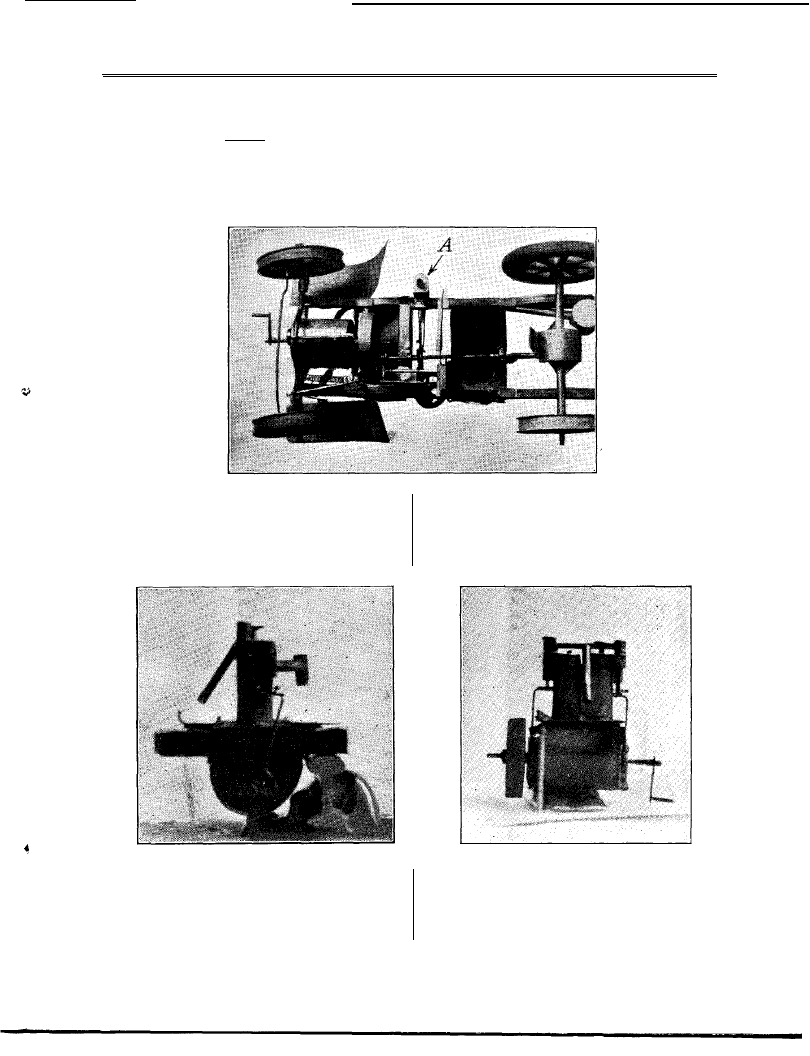
B y E . B . P A R K E R .
T
HE writer recently came across a working
model of a motor-car constructed over
eighteen years ago by a boy of seventeen.
The
chief point of interest in this piece of work lies
and the engine (Figs.
I
and 2), which is driven
by steam, was built to resemble a petrol engine.
It is of the single-acting type with twin cylinders
of about 5/8 in. bore by I
in. stroke, the cranks
are 180 deg apart. The cylinders, which are thin
brass tubes, are soldered together and let into a
tin plate forming the top of the crankcase, whilst
the cylinder heads are built up of sheet tin, and
unless one has attempted this kind of work it
Fig. 3.-Plan View of Car with Engine in Position.
in the ingenuity and patience evinced in its
construction.
The only tools used were a pair of tin shears,
a file, soldering iron, an archimedian drill and
a tap and die. The die was formed from a pole
is difficult to appreciate it. Sheet tin was used
for the crankcase, engine bearers, inlet and
exhaust pipes and lagging.
The pistons are of cast lead and were cast in
the cylinders, a wooden rod forming the core.
Fig. I.-End View of the Engine. Flg. Z.--Side View of Engine.
piece of an old compound magnet, in which
there was a tapped hole about 3-32nd in. in
diameter
;
a
piece of tool steel wire was threaded
in this die, fluted with a file and hardened.
The car is a model of a petrol engined car,
A packing recess was filed round the top of each
piston. Eccentric rods, connecting rods, and
the crankshaft are of wire, and the last, which
is 1/8 in. diameter, runs in bearings of brass tube.
The engine is fitted with poppet valves
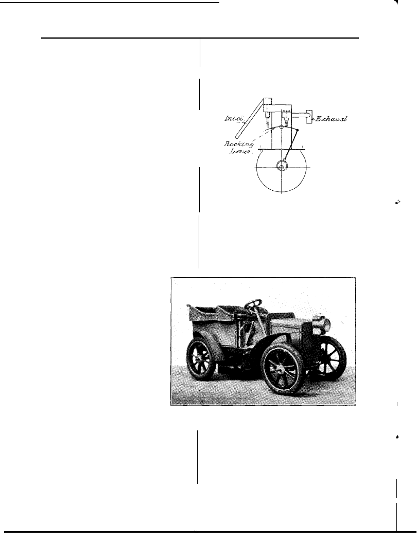
242
The Model Engineer and Electrician.
March 8, 1923.
by eccentrics, on the crankshaft, through
eccentric rods and rocking levers. There are
two eccentrics,, one to each cylinder, and each
eccentric actuates an inlet and an exhaust valve.
The rocking levers open the valves which are
returned to their seatings by springs. There is
a short interval between the closing of the inlet
valve and t h e opening of the e x h a u s t valve,
which permits s o m e d e g r e e o f e x p a n s i v e
working. Tin washers, 3-16th in. diameter,
form the valves, the wire stem passes through
the valve and is riveted and soldered in position.
The rocking levers, which are of clock spring,
are secured on their shafts by an ingenious
device
;
a spring, the last coil of which is of
reduced diameter, is fitted over the lever spindle
and the small coil slipped into a nick filed in
the spindle. In a similar manner the valve
springs are received.
The engine functioned very well at low and
at high speeds, and would turn over so slowly
that it seemed impossible for it to pass the
dead centres
;
steam pressure during trial varied
from 3-5 lbs. per sq. in.
In o r d e r t o ‘obtain the photographs, the engine
had been removed from the: car and the boiler
which supplied steam during the trial was simply
a half pound coffee tin standiag over a gas-ring.
The chief dimensions are given below :-
Length over-all, 4 1/2 ins.
Width over engine bearers 3 1/2 ins.; height
4 ins.
Cylinders, 5/8in. bore, 1 in. stroke.
C r a n k c a s e , 2 ins. in length and
1 5/8 ins. diameter.
F l y w h e e l ( o f c a s t l e a d ) , 2 ins.
diameter.
Weight about
IO
ozs.
Channel section girders of tin form
the chassis, the front and rear axles
are fitted with quarter and half elliptic
springs respectively, clock spring is the
material of which they are made.
The steering gear and the differen-
tial are the most interesting parts of
the chassis
;
the former, on the Acker-
mann system, is of the worm and
worm wheel type
;
t h e w o r m w a s
f o r m e d b y winding w i r e round t h e
steering wheel r o d and soldering it in
position
W h e e l s f r o m a n a l a r m c l o c k were
used in the construction of the differ-
ential, the teeth being carefully bent to
f o r m the bevei wheels.
states that the car mould travel about eighteen
feet and then stop for want of s t e a m but this
may be due t o the fact that the engine is geared
down considerabiy.
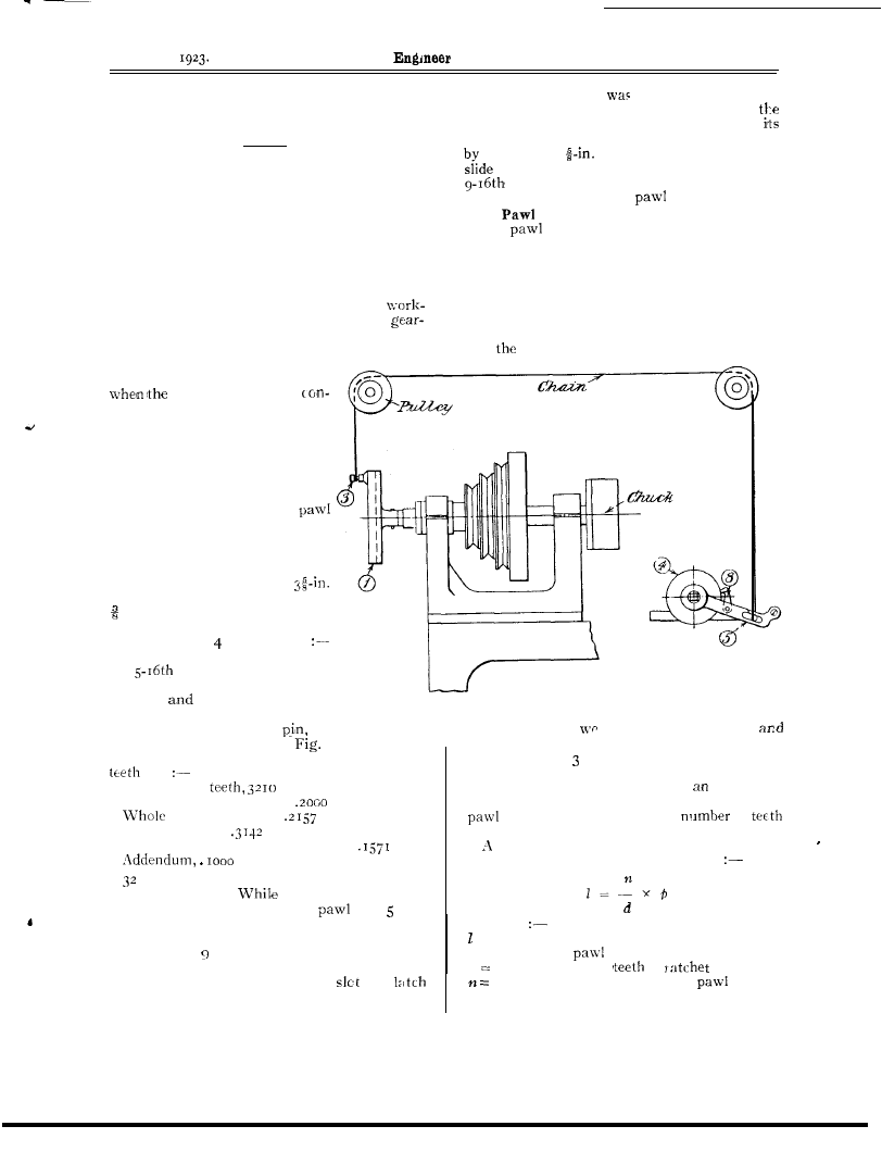
Just below the driver’s seat (Fig. 4) the: water
gauge may be seen, this gauge is really a glass
window in the boiler shell
;
the small lever to
Diagrammatic Sketch showing Valve Motion.
the right of the gauge is the throttle Fig. 3
shows the arrangement of the chassis; the feed
pump (.A) is actuated by an eccentric o n the pro-
peller shaft; the eccentric strap can be dis-
engaged from the sheave bv means of the lever
in front of the water gauge. (Fig. 4.)
A clock pinion forms the pump barrel, the
plunger is made from a piece of rod w h i c h
exactly fitted the hole in the pinion. The valve
A rectangular boiler is situated under the
front seat; it has an internal firebox, which is
fitted with three cross-water tubes, and the
fumes from the spirit lamp pass through a single
fuel tube, of rectangular section, the cutlet of
which is on the opposite side of the car to that
seen in Fig. 4. This boiler appears to be
deficient in steaming qualities,
the builder
Fig. 4.-The Model Car driven by the Experimental Steam Set.
chambers are made of sheet tin and the valves
were constructed in a similar manner to those
of the engine ; an incredible amount of patience
is displayed in the construction of this pump,
which functioned perfectly, but owing to the
iimited duration of run it was not required; this
explains the absence of t h e water tank.
The starting handle is used to start the
engine when it stopped on a dead centre.
March 8,
The Model
and Electrician.
243
Automatic Feed for
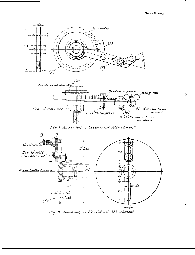
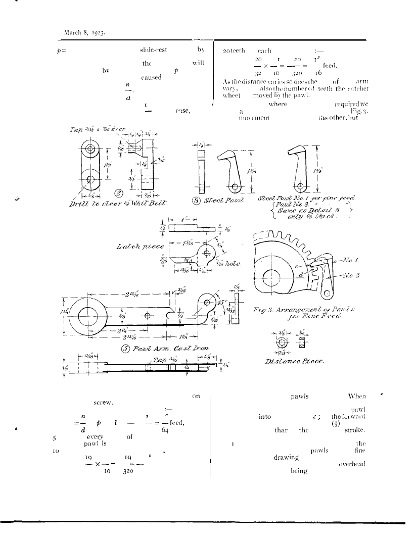
Surfacing in the Lathe.
By B. P
E D D E R
.
D.
URING a
rush of work some time ago it
was found necessary to bring into use a
non-screwcutting lathe that is generally reserved
for milling jobs, pattern-making and wood
turning. The headstock is backgeared and is
fitted with division plate and index, also the
spindle projects at the back a good way, and it
has been used to hold large diameter patterns
during wood turning, with a floor rest. There
is an overhead gear for driving from the
shop line shaft, and is used for milling,
cutting attachments, etc. The slide-rest has a
long surfacing slide on the bottom slide. The
gear here described was made up
t o r e n d e r t h e f e e d a u t o m a t i c
cross-slide was in
tinuous use.
The slide-rest spindle on the
cross-slide
is
s c r e w e d
IO
t.p.i.
square threads; but as the front
end did not project far enough to
take the gear in mind, a new
spindle was made to allow for
fitting the toothed wheel,
arm and nut and leave room for
an ordinary handle for running
the slide back for the next cut.
A hunt through the oddments box
resulted in the salvage of a
diameter cast-iron wheel blank
in. wide with large solid boss.
This casting was finished to the
sizes given in on drawing
Turned down to 3.4 ins. diameter
bv
in. wide, the over-all
width of boss was reduced, as
shown,
bored to be a tight
lit on spindle end, and is fixed by
means of a small taper
as
other end of the arm
machined both sides,
drilled and bored to be a nice easy fit on
spindle end, so that it will drop back under
own weight. It is prevented from coming
o f f
a standard
Whitworth lock-nut, the
s p i n d l e b e i n g t h r e a d e d
II
t . p . i . f o r
in. from the end just enough to take the
nut without binding the
arm.
T h e
(8).
The
is of steel filed to size, to fit the
teeth on the wheel, a distance piece being used
to bring it into position. This completes the
attachment as far as the slide-rest is concerned.
The Slotted Plate (1).
This was made out of an old scrap cast-iron
blank casting. The boss was bored out and
screwed to fit the end of the headstock spindle
and
slots milled out as per drawing, Fig. 2.
Arrangement of Drive for
Automatic Cross-Slide Feed.
shown in the
detail assembly drawing,
I
.
When finished so far it was rigged up and the
cut
Number of
D.P.
Working depth of tooth,
in.
depth of tooth,
in.
Circular pitch,
in.
Thickness of tooth on pitch line,
in.
in.
teeth works out well for various feeds, as
will be seen later.
the teeth were being
cut the wood pattern for the
arm was
put in hand.
The end of the arm was made to open to
allow the pin to be slipped off the arm, so that
the chain did not foul when running the slide
back at the end of the cut. The
and
piece were finished with a file, the boss at the
A wood pattern
had was altered to suit
used for the adjustable pin-holder part 2. This
allows the pin to be adjusted for position at
any point between centre and outer rim of plate
or beyond if desired. This effects adjustable
travel or pull on the chain that operates the
arm and also varies the
of
that the paw-1 moves over.
useful formulae for finding the amount of
travel or feed imparted to the tool is
Where
= The amount of feed given to tool at each
stroke of
arm
d Total number of
in
wheel.
Number of teeth covered by
in each
stroke.
244
The Model Engineer and Electrician.
GENERAL ARRANGEMENT OF ATTACHMENT FOR CROSS-SLIDE FEED.
The Model Engineer and Electrician.
24.5
P i t c h o f s c r e w o n
d r i v e n
for
stroke gives
ratchet wheel.
One
turn of the screw of
cross-slide
- -
move the tool an amount equal to and the
fraction of a revolution
by one stroke
lift the
of the arm will be =
a n d
i s
In the case
a fine feed is
The pitch of the screw is in this
the
used half-pitch ratchet, as shown in
IO
T h e
is similar to
‘it
Details of Components of Attachment for Cross-Slide Feed.
reciprocal of the number of threads per inch
the slide-rest
Applying the formula3 we obtain
5
I
1
X or =
X
32
IO
teeth for
stroke the arm.
When the
set to move the ratchet wheel
teeth for each stroke gives :-
I
I
_ _ f e e d
32
32
will be seen that two
are used.
the ratchet recedes on the back stroke pan-l
No. 2 climbs to the top of the tooth d and
No.
I
drops
the tooth at
on
stroke the wheel is carried one-half pitch of
tooth further on
on
preceding
On the next back stroke the process is reversed,
So. climbs, the tooth No. 2 drops into
space.
Details of the two
for the
feed are given on
The two cast-iron
pulleys
were fitted to hang from rhe
gear, the best positioa
found by trial.
The Model Engineer and Electrician.
The Drawing Competition
at the M.E.” Exhibition.
T h i s
feature
to
in its
t o m e c h a n i c a l
hobby and partly upon the
that model
enthusiasts not in
of tools and
S h o p f a c i l i t i e s m i g h t f i n d s u b s t i t u t e f o r
i n m a k i n g a d r a w i n g a n d
h a v i n g a n
to enter it in c o m p e t i -
tion.
The plan
as
experiment, and
f r o m t h e
is
to
a r e g u l a r
i n
o f
f o r
required to
on
or mount not exceeding
22 ins.
ins. or ins. by
II
ins., to be
t h e
of
c o m p e t i t o r - , b u t
o r
to
o r o c c u p a t i o n
T h e
to
m o d e l o f
k i n d
o r
t o o l o r
o f
o r
of k i n d u s e d o r
in
model
o f l a r g e e n g i n e s o r m a c h i n e s
n o t i n v i t e d .
i n k o r c o l o u r - m i g h t
their merits
of
not on the
points of
s u b j e c t
not eligible. c o n -
s i d e r a b l e a m o u n t o f
by these conditions,
as the
n u m b e r
o f
n o t l i m i t e d c o m p e t i t o r s h a d
f a i r o p p o r t u n i t y .
T h e r e s p o n s e w a s
e n t r i e s
sent in,
r a n g i n g f r o m f r e e h a n d s k e t c h
of a hand tool
a n d
o f e n g i n e s
to
colours and oil paintings and elaborate
working drawings. The competitors varied from
juniors a t
t o t h o s e o f m a t u r e a g e ,
occupations included a civil engineer, a saddler,
a r c h i t e c t ,
f i t t e r , a c i v i l
m e c h a n i c ,
p a t e n t a g e n t ’ s a s s i s t a n t , a
h o o t - s h o p a s s i s t a n t
a p a t t e r n m a k e r . T h e
judges
one silver and one
s i x t e e n d i p l o m a s o f
and
g r a d e s ,
t e n
a w a r d s o f t o t a l o f
T h e
o f t h e j u n i o r s
v e r y
c r e d i t a b l e
one considers how
in the
o f
o r
t h e
to years
is
to or actually
accomplish.
A
s i m i l a r r e m a r k i s
to
work
o f t h e c o m p e t i t o r ,
s e n t i n
o f a t r i p l e
e x p a n s i o n
engine,
t h e
o f
c l a s s
H i g h l y
for
m a n y
unable to make any
sort of
d r a w i n g .
The fitter who
Sent in a drawing of a model
engine is
deserving of praise, he likewise is awarded
d i p l o m a f o r
s a d d l e r ,
of
t h e
a
d i p l o m a p l u s a n a w a r d
of fifteen shillings
for w o r k i n g
o f a m o d e l
in
figures and
t o t h e m e d a l l i s t s , t h e
t o
g o o d
for m o d e l a r t i c u l a t e d l o c o m o t i v e , o r i g i n a l
design, c o l o u r e d a n d
e x c e l l e n t
degree neatness and the
well arranged
t h e b r o n z e w a s
to c o m p e t i t o r
sent in a coloured working drawing of a spiral
d i v i d i n g h e a d f o r a
T h i s s h o w e d
good standard of draughts-
m a n s h i p w i t h
v i e w s a n d s e c t i o n s ,
rendering the design understandable and clear
f o r t h e
T h i s c o m p e t i t o r
c o n g r a t u l a t i o n o n b e i n g a b l e t o
such
at
o f a g e .
good standard
o f
i n t h e d r a w i n g
a i-in.
locomotive sent in
t h e
t h i s
a
d i p l o m a - “
T h e p i c t u r e s
a n d g a v e v a r i e t y
to the competition,
c a n b c
o f
v e t b o t h
for
t h e y a r e i n t e n d e d t o b r .
Taking them in
of number the
is an
o i l
of
l o c o m o t i v e ,
cylinders depicting the
m o d e l
if it
f u l l - s i z e e n g i n e s t a n d i n g
u n d e r s t e a m
t h e p i c t o r i a l
effect in
is good and deserving of the
second-class diploma
for this qualifica-
t i o n . T h e o t h e r p i c t u r e i s a w a t e r c o l o u r
p a i n t i n g o f
s t e a m e n g i n e , t h e c o l o u r i n g i s b o l d a n d t h e
engine stands out
the competitor has made
g o o d a t t e m p t
a
s u b j e c t a n d
d e s e r v e s t h e d i p l o m a
to him, c o m -
m e n d e d f o r p i c t o r i a l e f f e c t . ”
A v e r y g o o d
of
drawing for m o d e l
horizontal engine
in
a g r i c u l t u r a l
the
of this is
n e a t
c o l o u r i n g
d i p l o m a - “
design in
for a
m o d e l c o m p o u n d
engine sent in by an
fitter y e a r s o f a g e i s q u i t e
j u n i o r
it
t e n
m o n e y
T h e r e
i l l u s -
t r a t i v e d r a w i n g s o f s p e c i a l c h a r a c t e r - o n e i n
pencil,
electro-magnetic motor, from
a
of age, is decidedly good
S e c o n d - c l a s s
T h e
o t h e r i s q u i t e a g o o d e x a m p l e o f a d r a w i n g
i n t e n d e d t o s h o w t h e a p p e a r a n c e o f m o d e l
a n d t h e s t e a m p l a n t t h e d e t a i l ,
and shading are simple and just
for the purpose intended.
C o m m e n d e d
for
General Effect.”

March 8, 1923.
The Model Engineer and Electrician.
247
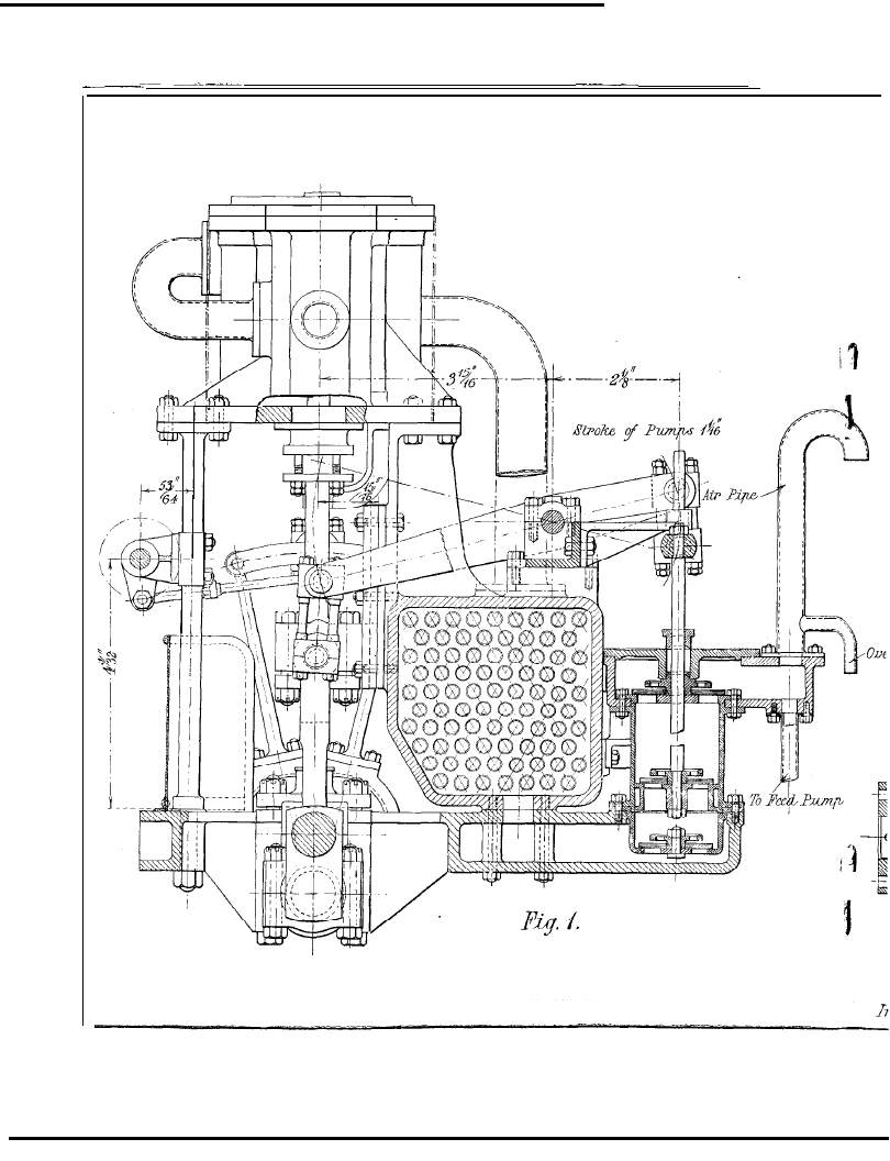
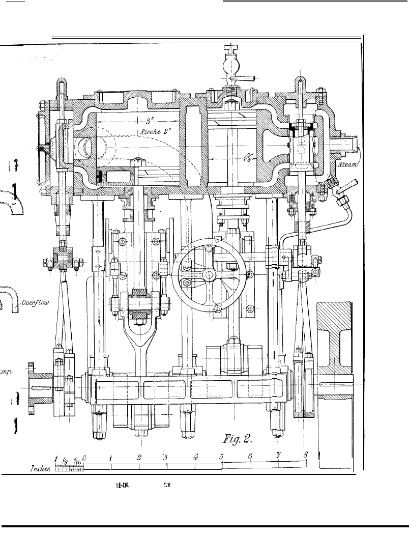
A Design
NO
model looks better, I
for a Model Compound Condensing
Steam Engine.
By “
think, than a well-
made compound steam engine. The
following is the result of an attempt made by-
the writer to furnish himself with working
drawings from which to make a model con-
densing engine. In designing the model, draw-
ings of a set of compound marine engines (with
H.P. and L.P. cylinder bore, of 13 ins. and
26
ins. diameter, and a stroke of 20 ins.) of a
kind usually installed in smal l coasting steamers
were kept in view as a type upon which to base
the design. Although not an exact copy of such
a class of engine, an attempt has been made to
retain the same general appearance. A good
working model is essentially a compromise, sim-
plicity of design and appearance being of first
importance. Also a r e a s o n a b l e efficiency is
expected of an engine built to be one that will
do something more than merely " go.”
The H. P. c y l n d e r bore is 1-3/4 ins. and the L.P.
cylinder 3 ins., giving a cylinder area ratio of
2.9: I. In order to keep down the over-al
height of the engine a rather short stroke of
2
ins. is used. A working pressure of 100 lbs.
per square inch, giving 500 as the m a x i m u m
revolutions per minute, has been assumed. The
engine is fitted with the usual
pumps driven by
levers operated by the L.P. engine. Liberal
bearing surface has been given to the working
parts and means of adjusting them provided
wherever thought necessary.
The valve gear is of the overhung type, with
all-round reversing gear. The H.P. engine is
fitted with a plain piston valve and the L.P.
with a flat valve. The condenser is fitted with
83 tubes 1/4 in. diameter. The bedplate is cored
out to form a chamber connecting the condenser
and air pump. The circulating pump is double-
acting and forces water into the condenser at
the L.P. end and discharges at t h e other, as
it was not thought necessary to fit a partition in
the condenser cover to obtain a return flow of
the cooling water. Figs.
I
a n d
2
sho w the
general arrangement of the model.
In describing the details of the engine, I will
consider the parts requiring castings first, com-
mencing with the bedplate, which is shown in
Fig. 3. The patterns should not be difficult to
make. The several facings on the upper surface
are all in the same plane. The bedplate has an
extension which carries the air-pump. A cham-
ber is cast in this extension, which connects the
air pump and condenser. A core box will be
required to form the core in moulding this
chamber. The pockets for the main bearings
and the recesses at the front and back
s h o u l d
Axle ”
also be cored out. The mould should bc
arranged to part at the underside of the top
flanges of the casting.
The bedplate should be cast in good cast-iron,
allowing I-16th in. on all the surfaces to be
machined. The casting should be free from
blowholes and spongy metal. Having obtained
a suitable casting, mark it off carefully to the
dimensions given in the drawing in the follow-
ing manner. Set the casting up on an angle-
plate so that the upper surface of casting stands
in the vertical plane with the underside towards
the angle plate and with the front of the casting
horizontal. The casting having been previously
whitened should have the centre lines corrc-
sponding w i t h the front columns, main bear-
ings,
condenser, and air pump plainly marked
with the scribing block sliding on the marking
off table. As these centre lines will be required
as guides in erecting the engine they should be
permanently marked in with a fine centre
punch. The centre lines at right angles to the
above-mentioned centre lines may now be
marked in, applying a square for this purpose.
Having obtained the chief centre lines the other
machining marks ran be located by compasses.
The holes for the front columns, main bearing
bolts and condenser fixing bolts can now be
marked in. To form a centre for the hole corre-
sponding with air pump barrel, a wooden plug
upon which is attached a piece of tinplate can be
fixed in the casting. The machining marks for
the upper surface and depth of pockets can be
marked on the casting if the scribing block is
applied to the angle plate.
The first machining operation should be the
planing of the underside of the casting, which
should be bolted upside down on the table of the
shaping machine. A cut should be taken across
the bottom to form a flat surface for the heads
of the main bearing bolts. The bottom flange of
the casting through which the holding bolts are
drilled should be just cleaned up. The casting
should now be turned over in order to machine
the top and the pockets. As before-mentioned,
the upper facings being all in one plane, they can
be machined all together. The casting should be
secured to the shaping machine table so that the
sides of the pockets can be machined at the same
setting. The table should now be turned
through 90 degs. so that the pockets can be
machined along the bottom and other sides.
The seating for the air pump barrel can be bored
out with a cutter bar after mounting the work
on an
angle plate attached to the lathe
saddle. The casting should now be drilled
248
The Model Engineer and Electrician.
March 8, 1923
GENERAL ARRANGEMENT DRAWINGS OF A M O D E L COMPOUND CONDENSING STEA
March 8 ,
1 9 2 3
The Model Engineer and Electrician.
249
ENSING STEAM ENGINE WITH CYLINDERS
AND 3-M.
Z-IN. STROKE.
250
The Yodel Enin
and tapped. The holes for the main
bearing bolts are 15-64th in. diameter drilled
right through the casting. Studs can, of course,
be used, holes tapped 7-32nd in. diameter and
1/2 in. deep being provided for this purpose. The
holes for the front columns are 5-16th in. dia-
meter and should be drilled perfectly square with
the upper surface ; 8 holes 9-64th in. diameter
arc drilled for the studs holding the condenser
t o the bedplate.
The four centre holes arc
drilled right through the casting, and should be
faced on the underside with a 5-I6th-in. pin
drill, to give a flat surface for the nuts. The air
pump barrel is secured to the brdplate with six
No. 5 B.A. studs, and the facing should be
drilled and tapped for the studs at least
7 - 3 2 n d deep.
The holes for the holding-
down b o l t s a r e 13-64th in. diamctcr t o s u i t
No. 2 B.A. bolts, four holes being drilled at
the
front and three at the back of the casting. The
casting should be filed up along the edges of the
flanges and the crank races
The port leading to
the air p u m p should be filed up to size if neces-
sary and the sharp corners should be taken off
the pockets for the main bearings.
The H.P. and L . P. cylinders are cast
tog:cther.
To facilitate the machining of the
L.
P
.
valve face, and to simplify the casting, the
I..P. steam-chest is attached as a separate cast-
ing to the main portion of the cylinders by
means of studs. Core hoses will be required for
forming the ports which art cast in the cvlin-
ders. The bottom of the casting is perfectly-flat.
The feet for securing the cylinders to the front
columns and condenser are extensions of the
bottom flange and have been arranged to give
the least trouble in mouldinc.
T h e piston-rod
stuffing boxes are separate from the cylinder
casting, so that the cores for the cylinder boxes
can be supported at both ends. With the excep-
tion of the core boxes little difficulty should be
encountered in the making of the pattern? for
the cylinders.
The cylinders should be made of close-grained
cast-iron,
sound
care being taken to obtain a clean,
casting. The casting should be
g
accurately marked off to the dimensions given in
Fig. 4.
The casting should be mounted on the face-
plate in the lathe and the bottom surface
machined right across. T his machined face will
then form a flat true surface for setting up the
casting for further machining.
It is probable that a lathe large enough to
swing the casting when boring the cylinders will
not be available, so that the boring out will be
done with a boring bar. If a lathe big enough
to take the casting set up on a faceplate is avail-
able (a gap-bed lathe of 5-in. to 6-in. centres at
the least will be required), then the casting
should be attached with the machined side to-
wards the faceplate and resting upon two
r and Electrician.
March 8, 1923.
-
-
parallel strips, so that the faceplate will clear
the tool when the holes for the stuffing hoses
are being bored out.
‘l‘he casting should be set up for boring out
the H.P. steam-chest first. As the casting will
be considerablv out of balance when rotating in
the lathe a suitable balance weight should be
placed on the faceplate opposite the casting.
The rough surface of the hole should first be
removed with a stiff flat drill, say 7/8 in. diameter,
which could be followed up with a
I
- 16th.in.
diameter twist drill. The finishino
c u t
should
be done w i t h a hooked boring tool
and care
should be taken to ensure a smooth and parallel
h o l e
If a
I
i n . d i a m e t e r parallel reamer i s
available the bore should be finished off with it,
but reamering is not essential. The top and
bottom of the steam-chest should be counter-
bored to suit the steam-chest covers.
The sharp
corners should be removed by chamfering at
45 degs. to say 1-64th in. to I-32nd in. deep.
The casting should now be moved on the face-
l)late a n d s e t true f o r b o r i n g o u t the H.1’.
cylinder.
A fairI y heavy cut should be taken a s
a first cut so as fo get well below the hard sur-
face. and using as stiff a boring bar as possible.
‘The cutting speed should not be too h i g h
and fairly light cuts should be taken after
the
first cut. The finishing cut should
be done with a broad, well-rounded tool.
A h o o k e d t o o l will be required for counter-
boring the bottom of the cylinder to I-16th in.
larger in diameter.
A
cu t can
be also taken
across the bottom, but it is not necessary if the
casting is clean and cast to the correct dimen-
sions. The top of the cylinder is counter-bored
1-16th in. larger in diameter to suit the H.P.
cylinder cover. The bore can of course be
ground to size, but as high a degree of precision
as necessary should be obtained without grind-
ing. The hole for the stuffing box should be
bored out at this setting. A similar procedure
be followed in boring
out
the
der. The
of the casting should be
right across the same setting.
The
valve face can be machined either in
the lathe or in the shaping machine, or if the
maker is skilful with the file and scraper, then
these tools may be used. In
case the scraper
will probably be used in bedding the slide valve
down to its face. This, however, will he
cussed later.
Should one’s
be too small carry the
casting on the faceplate, then the casting should
bolted to the lathe saddle. The casting is
ins. wide from the centre on one
so
it should easily
up on a
lathe.
,
The casting should be bored out with a
diameter boring bar held between the lathe
centres and
through the bottom of the
cylinder to be bored. Should the lathe not be
one possessing a sliding saddle, then the casting
The Model Engineer and Electrician.
he bolted directly on to the
bed, and
the traverse of
tool obtained arranging
the tool holder to slide along the boring bar.
T h i s c a n
be
in the following
T h e
is
out
on the boring
and is tapped to suit
passing through it. and which runs
one tooth
revolution of
of tripping device
to the lathe bed.
steam inlet boss is tapped
B.S. pipe,
to suit the steam-pipe union. The boss should
with I-in. diameter pin drill
T h e
from the
cylinder is a
diameter drilled
Plan and Sectional Elevation of the Engine Bedplate.
parallel to the boring bar.
lead-screw is
boss for the H.P. exhaust pipe should be faced
held at the front end by means of a collar, in
either in the lathe or with a pin drill, and also
which the lead-screw can rotate but not move
be tapped for the studs securing the exhaust
endwavs.
Bv rotating the lead-screw (which
Whitworth thread); the
pipe.
The exhaust passage from the L.P.
h a s ,
a
cylinder is a
diameter hole drilled obliquely
holder is moved along the boring bar. To cause
through into the exhaust port.
The exhaust
rotation of the lead-screw a small star wheel is
pipe boss should be faced and tapped for the
mounted at the front end and which is moved
studs securing the exhaust pipe.
The Model Engineer and Electrician.
.\I
8,
March 8,
The Model Engineer and Electrician.
The tapped holes for
the
H . P . a n d
L . P .
cylinder covers and steam-chests will be dealt
with later, as they should not be drilled until the
to be attached to the cylinder are ready for
iitting.
Three holes for the drains are tapped in.
The body of the condenser is shown in Fig.
It is made of gun-metal, and the interior is
cored out.
Having obtained a good casting, it
should be prepared for marking off.
First
lightly machine the two faces of the columns
upon which the guide plates fit, machining the
Part
Sectional Elevations
Plan of the
Condenser Body.
diameter and
in the cylinders at the
bottom of the steam ports, as shown on the
drawing. The holes
the screws securing the
lagging are tapped No. 8 B.A. and in. deep,
and are situated in. from the
the cast-
ing and spaced about
ins.
a p a r t a s
symmetrically as possible around the flanges.
faces at the same
if
to
that
are parallel and in the same plane.
The
can now be set up on the surface
plate and marked off from these accurate sur-
faces very carefully.
The facings for the guide plates may now be
machined down to the right depth. The ends
The Model Engineer and
of the casting should be faced next. This may
be done in the lathe. Secure the casting on an
angle plate with guide faces downwards and
with one end towards the faceplate. The outer
end may then be faced across. The
may
now be turned end for end and again machined.
The tops of the columns, the feet carrying the
bearings for the pump levers, and the facings at
the back and bottom of the castings, can be
machined at one setting in the shaping machine.
This, of course, depends entirely upon the tools
at the maker’s disposal, and many of the parts
which would be usually machined can be
finished with the file and scraper when in
skilful hands. The guide plates are secured to
the columns with four No. 4 B.A. studs and two
o. 4 B.A. bolts in each, and the columns should
be drilled and tapped accordingly.
The holes for the screws holding the bearings
for the pump levers and the bolts holding the
cylinders should be left undrilled until the time
comes for fitting up these parts.
The condenser body should now temporarily
be clamped to the bedplate, so that the holes in
the bottom may be
off for drilling and
tapping.
The centre lines on the condenser
should register accurately with those on the
bedplate, and the guide surfaces should be per-
fectly parallel and square to the main bearing
pockets before the holes are marked off. Eight
No. B.A. studs secure the condenser to the
bedplate. The boss the top of the condenser
to which the exhaust pipe is attached is drilled
in. and also tapped No. B.A. for the four
screws securing the exhaust pipe. A small boss
is provided which is drilled and tapped to suit
the connections for attaching a vacuum gauge
be continued.)
Watt Colliery Engines.
AN
interesting
correspondence
between
and a
f i r m , w r i t t e n
the years
and 1781, has recently
published in South Wales. It relates to
proposals for
of a colliery engine,
and James
informs his correspondent that
he proposed to install an engine with a cylinder
ins in diameter
an 8 ft. stroke, making
8 strokes per minute. He estimated that this
would require about bushels of coal per
hours, provided that a proper boyler, such
as are used in Cornwall were employed.
It has been estimated that this engine
would have an output of about 30 b.h.p., with
a coal consumption of something less than 7 Ibs.
per
hour. Now, Watts’ engines were
erected on a profit-sharing basis under which
his firm received the value of one-third of all
the coal saved, and a
engine of
the period
nearly
18
lbs. of coal
per
hour, it wili be seen that his profts
would
very considerable.
Radio Engineering.
The Licence Difficulty : ‘A Suggestion.
In view of the apparent deadlock at present
concerning the issue of licences for the
of wireless to those amateurs
who
desire
to construct their own apparatus, the
following suggestions are put
as a
possible solution of
the difficulty
which
undoubtedly exists.
There are at the moment three
distinct
classes of wireless amateurs :-
(
I
) Those who desire simply to receive broad-
cast telephony and are content to purchase
c o m p l e t e s e t s b e a r i n g
B.B.C. mark of
approval.
(2)
Those who desire to receive broadcast
telephony, but who prefer to construct their
own
apparatus of
or less stereotvped
design and
from components of what- are
practically standard pattern.
(3) Those
who
w i s h
construct, o r
assemble, their own apparatus for experimental
or lesser
a n d t o
whom broadcast telephony
secondary consideration.
is probably a
As matters stand, those in the first group are
easily and simply catered for by the issue of
broadcast licences from all post-offices. The
and the
each receive their due
share of
fees paid and the
can set
to work.
same time,
is a grow-
ing feeling that in some instances the
facturors forming the
are charging
prices
for their products which smack of
profiteering.”
Those in the second group form the
They are not true
“ - t h o u g h
many of them mav later become such-and the
paragraph in Form
requiring them to state
previous
in the use of wireless
h i t s
So also does the
paragraph requiring them state the nature of
the
desire to conduct.
of them have no
to be classed as
a n d
r e a l e a r n e s t e x p e r i -
menter is rather put about that such individuals
are
upon the
plane as himself.
this brings us to the
group, the
of which are
most of all, as
until the
concerning the second is
settled, those in the third must wait.
It must have been foreseen that some such
position nould arise, and the blame for the
present deadlock must be placed
upon
those
circulated such glowing pictures of
t h e f u t u r e o f
o f
b r o a d c a s t i n g - w i t h o u t , a t t h e
same
time,
giving’ the general public a
of
what they might and might not do.
Con-
sequently thousands, from schoolboy to grey-
The Model Engineer and Electrician.
255
beard,
to prepare for broadcasting,
societies might well justify their existence by
and there are
hundreds firms-manu-
c a t e r i n g f o r t h e w o u l d - b e
b y
facturers and
day and
upon the supply of parts and
and,
arranging lectures on sufficient
as will
enable him to carry out his
work
more impressive still, several periodicals the
intelligently than he
might per-
main
objects
o f w h i c h a r e
the
haps do.
In the writer’s opinion, a wireless
difficulties of, and offer advice to, this very class
which exists simply for listening-in
of so-calied experimenter, and to provide adver-
is not worth joining.
t i s e m e n t
of
side by
demonstrations or
research
side with the retailers of small parts
after
members’ a p p a r a t u s b y a l l m e a n s ,
let
bring no
to the
instruction be the main object of the society.
present unsatisfactory state of
is
breeding a
host of
s t a t i o n s .
Every
of these lines, in common with the
writer,
of. many who have built, or are
building, a
h a v e
and
not, apparently, trouble about
because, as
they
say, a broadcast licence is of no use
to
‘and
cannot hope to obtain
11
licence.
There is no use in
blinking what are hard facts.
Now, what is the
to be? The writer
suggest leaving the first and
groups
o f a m a t e u r s a s
a r e .
If
t h e
experimenter’s licence, as it stands,
be
impossible to obtain unless
of techni-
cal
forthcoming.
great deal
o f t h e
n - o u l d t h e n
automatically cease.
Finally, it is be hoped that
and
solution to the licence difficulty is
attained the authorities will make it their busi-
ness to round up
punish severely those
erect and use unlicensed apparatus.
Just
now there is a growing feeling that amateurs
are perfectly willing play the game
are
coerced into obtaining a broadcast
l i c e n c e a g a i n s t
the
broadcasting scheme was set on foot to suit the
public, not vice versa.
The writer is unwilling
to believe that such an attitude is
or
but things obviously cannot
remain as they are.
Replies to Wireless Enquiries.
In
to meet the present
the
writer would suggest the issue of a modified
broadcast licence calling it a
licence or some
title which should be
The procedure would be as
Let individual construct his set, and
on its
let him present it for exami-
nation
approval or disapproval) to some
competent and
examiner.
chief
P.O.
of the town or district should
surely be competent to pass a
opinion on
a s e t o f t h e k i n d u n d e r
O r ,
the officials of the local wireless
society or association might be
with
such powers.
from some such
recognised
t h e
with a signed statemenr to
effect, n-ould
proceed to the nearest post-office.
his
licence, pay his fee for the same,
at the
same
and
purchase an
label,
paying a
for
same appropriate to the
nature of his set. This label
be
to
set and there the
would end. The
mill get his share of the licence fee,
the
g e t t h e i r r o y a l t y . I n
addition this, the small traders
continue
to find a market for their wares. Beyond this,
the writer believes there will
a greater
constructor to produce better
w o r k . I f h e
h i s s e t w i l l b e
scrutinised he will feel it up to him”’ to show
something better than he might otherwise put
together.
T h e
h u n d r e d c d d w i r e l e s s
E.
H.
(Funchal).-(I)
mfds. and
mfds. respectively.
(2)
Inductances wound on
cylindrical formers.
(3) Either in the earth lead
or through a transformer inserted directly in the
grid lead.
J. G. T. (Doncaster).-Our correspondent
asks for a useful three-valve circuit.
C. (Thornton Heath).-Loud speakers can-
not be used with crystal detectors some form
must be
the Brown r e l a y
E. L.
Y o u
F o r t h e
circuit use
mfd. for
secondary,
( 2 )
(3) Primary, 62
lb.) for secondary, 80 yards lb.). Your
sketch is not
correct; you
put the
aerial
in series with the inductance,
and not in parallel, as you have shown it.
G. B. C. (Enfield).-Your aerial and earth are
quite O.K. There is no need to place a switch
as shown in
sketch, though it would
function admirably. Place it indooss just
the lead-in and earth are brought to
set.
T h e
brought to the
a n d
from this to two terminals.
in use
the aerial and
are joined directly by this
switch. If you care
extra safeguard, take
a short, stout wire from each terminal,
the ends of the wires be points and about mm.
apart. Static discharges will spark across these
points, and such sparks should be a warning
to cease work and close the
The Model Engineer and Eleotriaian.
W. H. 0. (Birmingham).-You
use a
crystal set of any make directly with a loud-
speaker; there must be
of amplify-
ing the rectified signals from the crystal. This
is most conveniently done by employing one or
more valves as amplifiers.
Such a
has
disadvantage that any noises set up in the
crystal circuits
very much magnified,
and there may be, in addition,
set up in
the valve circuits.
a r e r a r e l y
The cost of a single-valve amplifier
the necessary valve, accumulator and
tension
would be least
R. (Walworth).-The sketch below gives
the
you ask
viz., a
on the unit panel system comprising H.F.,
detector, and L.F.
E. J. V. (Manor Park).-Yes. See our book
W i r e l e s s A p p a r a t u s M a k i n g by
A. V.
least three valves to give you the results you
desire and the best arrangement of these
be, one H.F., one detector, and one L.F. As
to cost, that will very much depend upon the
amount of work you are prepared to put into
the set and also upon the quality of its com-
ponents.
If you consider that you will
a tuning inductance (lattice coil preferable),
H.F. transformer, L.F. transformer, two fila-
ment resistances,
variable condensers, three
block condensers, three valve holders, three
valves, two pairs of ‘phones, a H.T. battery and
a
accumulator of fairly large capacity, you
can by reference to advertisers’ lists compute
the cost of the bare necessaries.
Reference to
Fig. in
Wireless Circuits will give you
the type of circuit, but you would omit one H.F.
and one L.F. valve. Write again if you intend
to proceed, saying exactly what you intend doing.
Diagram of Three-Valve Circuit
the Unit
System.
Ballhatchet, price 3s. gd., post free, from our
Publishing Department, 66, Farringdon Street,
E.C.4.
F. S. (Shanklin) .-You do not state over what
range of wave-lengths you desire to work, so
that it is impossible to help you.
If you wind
the outer tube with about
turns of No.
wire, and the inner with about
turns of
No. wire you should have a
up to
about
metres.
A. H.
.-(
I
) You will require
a variable condenser of about
mfd. maxi-
mum capacity across your secondary inductance.
The circuit, otherwise, is correct.
Refer-
ence to the maker’s
will enable you to obtain
the correct coils.
(3) Yes honeycomb coils are
very rarely tapped, the adjustment being made
by means of small variable condenser.
G . D .
i s very doubtful
whether, under the conditions you specify, you
would get satisfactory (if any) results with a
single-valve circuit. Your aerial is very small
and very low.
You will probably require at
C. G. B. (Cardiff).-(I) Without particulars
of your inductance coil it is impossible to say
exactly what you can do with your set.
Most
probably you cannot tune down sufficiently low
for telephony in other
your coil
large, and you must get a
one. The
circuit you propose nould not be
by
the P.M.G. as it involves reaction.
Basket
coils would be preferable.
You can obtain
exactly what you require from any good dealer
if you state your exact requirements.
(3)
47 in Wireless
shows the principle
of H.F. amplification followed by a valve as
detector.
You can adapt the circuit
easily
by omitting the first valve and putting the
‘phones in place of the L.F. transformer shown.
N.
See p. of Wireless
Apparatus Making.”
It is regretted that
there does not seem to be any such information
It is hoped discuss this matter at
an early date.
T. H. (Chester).---You are undoubtedly
suffering from disturbances from the trams, and
March 8,
The Model Engineer and
it is very unfortunate that there is no real
remedy. You might, however, take extra pre-
cautions to have perfect insulation at all points,
to insulating
baseboard of your set
from the bench.
J. V. (Manor Park)
- (
I
)
The tubes should
be quite suitable, though you do not say how
thick
are. Judging from your figures they
would seem to be fairly thin, however. The
smaller one need be no longer than the larger,
shorter
would
do. in fact.
Distance is quite
suitable.
(3)
primary full with No.
enamelled, and the secondary full with
28
enamelled. (4) You will require a small
able condenser in each circuit to give good
results capacity about
mfd. Range
then be about
metres.
J. (Wanstead).-Your query is receiving
special attention.
L. C.
Y e s .
Yes
separate control by all means.
( 3 )
telephones will be quite satisfactory
ohms
will be too low.
(4) Basket inductances will
though the usual spool wound H.F. trans-
former will be better.
S . ( H a m p s t e a d ) . - Y o u a r e a s k i n g t h e
impossible.
It has been stated on more than one
occasion that you cannot use a loud-speaker in
conjunction with a crystal
If you wish
to experiment in this direction you might try
using a Brown relay.
C. (Falkirk).--(~) You can, by adding a
suitable horn, amplify the sounds given by an
ordinary telephone receiver, but it will not be,
correctly speaking, a loud-speaker.”
Such
instruments are of special design and con-
struction.
Ordinary telephones are rarely
very successful when re-wound.
You might try
putting oz. of No. 44
on each magnet
and you will probably require much
thinner diaphragms.
( 3 ) S a m p l e s o f w i r e
enclosed are: No. 42,
(2) No.
(3)
No. 38.
W. J. B. (Leytonstone).-Use the three
you have. The principle is exactly the same.
In the diagram you mention the coil marked
A.C.C. is a portion of the A.T.I. but is shown
as in the original set the coupling
the
and
was brought about
by a variometer.
H.
P. (Leicester).-By using a
twin
aerial ft. high, and
critical adjustments,
vou would
telephony from Birming-
ham.
Twenty-five miles is a good average range
for receiving broadcast telephony on a crystal
set. To obtain good results we would advise
you to
at
set.
B. M. I).
(
I
) N
O
.
miles.
from
our
ea ers.
of Model
To
OF
The
Model Engineer.
S
I R
, - A
S
a
keen model engineer and
$-in.
scale loco. enthusiast I always enjoy
rending the remarks
scale model
and their supposed hauling capacity, also the
fire tube and water tube controversy.
I really
think it is time that model loco. engineers
adopted a commonsense method of testing the
hauling capacity of their engines. The owner
of any
scale loco. could easily construct
special truck with axles running on
hearings that would only require a few
draw-bar pull to haul a ton weight, so that his
claim for fhe apparently exaggerated hauling
capacity of his loco. may be quite justified
The only true and correct method of testing a
loco.
it be a model or full size is to
weigh the draw-bar pull.
Thus a good steaming
model with correct motion work, etc., but
perhaps light in weight would have the same
draw-bar pull as an inferior model of greater
weight with better adhesion.
All that is
necessary to carry out this test is a short
of track on a table or other raised structure.
with a small grooved pulley at one end of
track and with a scale pan and weights attached
to one end of a depending cord, the other end
being fastened to the tender draw hook. Then
the maximum weight that the loco. will just
lift at full steam pressure is the correct
bar pull, and the
and only true measure of
a
remain, yours truly,
G
E O
.
H.
Insulating Varnish.
OF
T h e Model
to the article on this
subject in your issue of January 4, the views
expressed therein are eminently practical and
accurate. The
however, which con-
fronts amateurs in using a stoving quality of
insulating varnish is practically insurmountable,
they are obliged to use an
drving varnish. This, in order to obtain most
satisfactory results, should be of high dielectric
d
quality many of the
called shellac varnishes offered to amateurs are
diluted with rosin and soft gum, and to this
may be attributed some of the unsatisfactory
features mentioned in your article.
For the ordinary requirements of amateurs,
pure genuine shellac varnish will, speaking
generally, fulfil all purposes necessary, provided
care is taken that the work on which the
varnish is to be applied is free from moisture
prior to application and that the bottle
The Model
and Electrician.
taining the shellac varnish is kept tightly
corked, also stored a drv
To meet the
amateurs I am
in a position to supply, put up in small bottles
or tins,
(
I
)
varnish
pure shellac spirit
quick-drying golden
varnish
(similar in essential properties to the first
(3) air-drying
latter takes t w e l v e h o u r s
to dry, and if the work in hand permits, is
strongly recommended on account of its far
superior
insulating
properties
and higher
dielectric resistivity.-Yours faithfully,
B
A T E S
.
Building Working
Traction Engines.
To
THE
E
DITOR OF
The Model Engineer.
D
BAR
see in the issue for December
28 a letter from a correspondent whb signs him-
self C. S. G., and is asking for information re
a model traction engine.
As no one has replied
I should like to say a few words on the subject.
I
I may claim to be one of the oldest
makers of model tractions, having completed my
first one in 1887 at the age of
Nom,
Mr. C. S. G. says he does not want to
pay above
outside well, he may be
enough to find someone who has a fairly good
model and would be willing to sell the above
figure, but even if he is the possessor of good
luck he can rest
that he cannot get even
a fairly good one made at anywhere near that
price.
In the first
a good steaming and
safe boiler with necessary mountings will cost
least that sum.
I take it he does not want a
dud,” which would be liable blow the house
Next, the road wheels, to be anything like the
real thing, demand lot of work in them and
cannot be
cast from
simple
patterns in
model loco. wheels are.
O f
course differential
can be omitted (steam
ploughing engines and rollers
none), but
it must have a steering gear of some sort,
even if of the simplest
adds to the cost
there must also be a bunker and
tank
forming the
that the boiler uses solid fuel no
oil tank will be needed, but as yet we have no
cylinder (it is possible to obtain cylinders from
stock but they would make an unsatisfactory
job, a special one being far the better). This
would have be made to fit the boiler and have
regulation and safety valves on top.
Now there
is still all the motion and travelling gear to be
made.
These are a few of the points to be
when quoting for a
traction engine,
and I think very few people realise the amount
of work required in
good model railway
locomotive can be made much easier.
I should be pleased to help C. S. G. or anyone
on traction engines or traction engine matters,
either
your columns (if of sufficient
interest) or direct.-Yours faithfully,
M
A L C O L M
S.
-
-
Square Rig Vessels.
To
THE
OF
The Model Engineer.
D
E A R
reference to
Clinton’s
remarks in his letter in December issue.
The
original model is ins. over-all, ins.
ins. beam deck, ins. waterline. The
stations in the drawing
was full size)
are 3 ins.
appears to have been photographed
down to about
scale.
Yards shifting when braced ? I never found
t h i s t o
the main brace, if properly
adjusted, keeps all quite rigid.
It would be most interesting if Mr. Clayton
would sav if his model is to scale, also if the
scantlings, ballast, etc., are also to scale and
if the sail area is also to the scale of the real
vessel.
it has been
considered quite
impossible for a model built to scale to carry
canvas to scale.
In the
Lark model, which
fetched
for
Cross, I had to
twice
the displacement of the real vessel to carry the
full sails, studding sails, stay sails, ring-sail,
etc., from the waterline. This was an exact
model of the real vessel, with all guns, boats
and fittings below the waterline her displace-
ment was much greater than the real vessel,
This model carried her canvas and sailed
Yours faithfully,
C.
H
I C K S
.
Galvos.
To
THE
E
DITOR
The Model Engineer.
D
EAR
the
a r t i c l e
G.L.A.,” describing suspended coil
in your issue of January
I was,
like him, in sore need of sensitive instrument.
and could not think paying the prices asked
by first-class makers.
My decision,
n-as to make portable
instrument, and the sensitiveness of the first
one, made at a total cost of about two shillings,
was so gratifying that I spent a few shillings
more in buying a magnet, made to my size,
from specialists in magnet manufacture.
Two instruments were made, and the results
obtained may be interesting to some of your
readers.
No.
I
mound with
turns of No.
wire to a resistance of 32 ohms. The scale is
over ins. long, and is divided with m a i n
divisions, each these being divided
divisions in all.
Full reading is 3 milliamperes,
s m a l l s p a c e i n d i c a t i n g
of a
is easily read.
Shunts have been added, making it read
6 0
milliamps at full scale. and 3 amps. also
shunt).
March 8,
The Model Engineer and Electrician.
This instrument is invaluable to me, and has
had constant handling for 3 years, testing insu-
lation resistance-up about megohns on 230
volt circuits--current taken by telephone trans-
mitters and receivers, by electric lamps and
also on largest range, as ammeter in
charging small accumulators.
No. 2 instrument is
to 700 ohms, with
No. 47 wire.
It
e a s i l y s h o w
I
- 2 0 0 , 0 0 0
ampere, and, used as a ballistic galvo., will,
for instance,
an indication of the static
capacity of a
conduit wiring job.-Yours
faithfully,
A. 0.
Society and Club Doings.
arc
that notices of
forthcoming meetings must
reach 10
to
given
Model Engineering.
The Society of Model Experimental Engineers.
On Monday, February
some
members
listened in,” when Mr. H. Hildersley gave
his interesting exposition on Elementary
Wireless,
interspersed, as it was, with valu-
able information about licences, aerials, and
receiving sets, etc.
at Caxton Hall, at o’clock.
A. Proctor
M i t c h e l l o n The Ravenglass and
Miniature Railway.
Subsequent
meetings,
Wednesday, April
I I
,
May 2, and
Thursday May
--At each ordinary meeting
there are competitions for the Challenge Shield
and the Bronze Plaque and Medal the parti-
culars and conditions are on the notice board
at the meetings or may be obtained from the
Secretary on application.
A. J. R. Lamb, Room
Windsor
Victoria Street, Westminster,
He is still
in h o p e f u l a n t i c i p a -
tion of the arrival of the subscriptions in
arrears.
Don’t disappoint him.
The
boxes so ably handled bv Mrs.
Hart and Mrs. Bunt within the track enclosure
at the
Exhibition have enabled the Trea-
surer to pass on the
of
to each of the
R o y a l N a t i o n a l L i f e -
b o a t I n s t i t u t i o n and The Lord Roberts
Memorial Workshops Fund, from both of
w h i c h g r a t e f u l
have been
received.
Monday, March
at
o’clock
T u r n i n g , ” b y M r .
G.
26, Marking Out,” by
Mr. R. A.
Rummage sale, Monday, April
S e c r e t a r y , M r . J.
Road, Gravesend, Kc:- t.
Model Railway Club.
An ordinary meeting of the Model Railway
Club
held at St. John’s Schools, Tottenham
Court Road, on
February 22,
After the reading of the minutes a n d
transaction of forma1 business, the chairman for
the evening (Mr. W. R. Smart) called on
the Secretary for his paper on Making Model
Signal Parts.
This paper dealt with a simple
and cheap method of making in brass sheet
rod the parts necessary for a model signal,
to be of grea: interest to the members,
who bombarded the lecturer with questions.
Mr. Saunders (a visitor) then proceeded
demonstrate an easy and inexpensive method of
working signals by electricity, and exhibited an
ingenious form of two-arm signal working from
one lever, which also works a brake stop. This
s i g n a l
he has himself designed for 0
gauge will shortly be on the market.
Hon. Secretary, T. W. P
I T T
, 17, Northumber-
land Avenue,
Park,
The Bristol Society of Experimental Engineers
and Craftsmen.
Chains
and Chain Making,” Hv. G. Priest, the Secre-
tary, who will deal
cable chain making
generally.
The journal Our Cog,” No. 5 will be issued
at the first meeting the month.
H o n . S e c r e t a r y ,
G.
2 7 8 , B a t h
Road, Bristol.
Manchester Society of Model Experimental
Engineers.
An ordinary meeting of the Society was held
on Tuesday, February
20,
at headquarters,
Clarion
Market Street, City. Three new
members were elected The next meeting is
on March
20
an auction sale will be held.
The meeting which should take place on April
3 next is
owing to Easter April
will therefore be the only meeting during that
month. O n M a y
I
M r . W r i g h t w i l l g i v e a
paper on
Springs.
This should be very
interesting and shou be well attended. Two
lantern lectures are on the programme for the
near future.
a w e l l - m a d e a n d
efficient air compressor pump; visitor, a well-
made vertical steam engine Mr. Mills, a very
neat vertical marine steam engine.
If in town
the next meeting, by the way, Mr. Mills will
give a short paper on Failures.” This should
be specially interesting.
Secretary, pamphlet
describing the Alklum accumulators, which
appear good but a little stiff in price as things
Messrs. Firth’s catalogue, kindly sent by
the firm, too well known for comment, also
several numbers of the Cog,” the journal of
the
Society.
2 6 0
The Model Engineer and Electrician.
A few outstanding subscriptions still remain
and would be welcomed.
It is to be hoped that
good attendance will be seen at the next
meeting.
An invitation will be extended to any-
one interested in the Society if they will com-
municate with the Secretary.
R .
S
T U A R T
H o n . S e c r e t a r y ,
Stretford Road,
The Glasgow Society of Model Craftsmen.
The Glasgow Society of Model Craftsmen held
February meeting in the Society Room,
Royal Technical College, on Thursday evening
/(February
at
p.m. Mr. James Welsh
presiding.
The subject for the evening was
Screw Threads,” and was dealt with by W. E.
Pickerel!, Esq. The
in the course of
his paper, described methods of gauging and
measuring as devised at the N.P.L., and slides
illustrating the
used were projected on
screen.
Time did not permit the actual production of
screws
dealt with
So
a very limited
period was
for discussion.
member
created an uproar by stating he had discovered
a Whitworth screw in a flint-lock (which some
facetious fellow member declared had been used
by
l a t e K i n g T u t a n k h a m e n
The
gravely remarked that Sir Joshua
worth had not
screws, but had sug-
gested a basis for standardising.
Headquarters are now fixed. The Governors
of the Royal Technical College having agreed
to grant us the use of the Society Room for
field-days (nights) and of the Committee
room on other
T o - n i g h t , M a r c h A. J. Fisher, Esq..
Convenor of the Wireless Section, will lecture
on Wireless Apparatus,” and will
his experimental set.
Will members please remember that tne
venors of Sections have been elected for dealing
with and are responsible for questions relating
to their Sections. If there is any difficulty on
the part of any member in getting needed infor-
mation or getting in touch with any other
member with a view of discussing models or
relative matter, a note handed or posted to the
Hon. Secretary will receive immediate attention.
D. C.
Hon. Secretary,
Berkeley
Street,
Dublin S.M. E.E.
This Society met in University College, on
Friday, February
when Mr. T. Robinson
a lecture on
Internal Combustion
Engines. He began by a short description of
the action of the two classes of internal com-
bustion engines,
The Four Cycle Type and
The Two Cycle Type,” and’ confined his
remarks chiefly to those in motor-car and aero-
plane work. He traced the various
m e n t s w h i c h h a v e t a k e n p l a c e a s r e g a r d s
ignition
devices,
camshafts,
carburettors.
bearings, etc., and spoke at some length on the
question of valves and timing and lubrication
and
some interesting details regarding the
Rolls Royce
aeroplane engines.
At the next
on March Mr H.
will read a paper on Electric Under-
ground Railways,” the lecture and slides being
loaned by the Electric Underground Co.
Hon. Secretary,
Park, Rathgar, Dublin.
Wireless.
The Radio Society of Great Britain.
A
ail! be given by L. F.
Esq.,
A.M.I.E.E., at the Institution of Electrical
Engineers, Savoy Place, Victoria Embankment,
at 6.30 p.m. on March 16, entitled Accumu-
lators, Dry Cells, and the Currents used in the
Reception of Radio
illustrated by
experiments.
This elementary lecture is intended for the
Associate class of this Society, but anyone
a n admission card by
forwarding a large stamped addressed envelope
to
Hon.
Secretary,
LESLIE
M.Inst.R.E.,
Quex Road, West Hampstead,
X.W.6.
_
Notices.
The
Editor invites correspondence and original contributions
on all
motor and electrical
intended for
should be
written on one
side of the paper only. and should invariably bear the sender’s
and
It should be distinctly stated, when sending
whether remuneration is expected, or not, and all
should be
by a stamped envelope addressed
for return in the
of
Readers desiring to
the
Editor personally can
do so by making an appointment in
All subscriptions and correspondence
to sales of the
paper and books tc be addressed to
Co., 66,
Street, London,
Annual Subscription, Xd.,
post tree to all parts of the world.
All correspondence relating to Advertisements and deposits to
be addressed to
“The Model
Engineer,” 66,
Street, London,
Sole Agents for
States, Canada, and
and
Chamberlain,
Street? New York, U.S.A., to whom all
subscriptions from
should be addressed.
Single
copies, cents
dollars, cents, post free.
Contents.
The
asterisk denotes
subject
is illustrated
O u r P o i n t o f
.
2
3
7
Locomotive
and Notes*
.
A Model Experimental Steam Car*
Automatic Feed for Surfacing in the
The Drawing Competition at the
Exhibition
A Design for a Model Compound Con
Steam Engine*
Radio Engineering*
Practical Letters from our Readers
Society and Club Doings .
.
Wyszukiwarka
Podobne podstrony:
1141
1141
1141, ●GOTOWE TŁA
1141
więcej podobnych podstron