
EUROPEAN STANDARD
EN 1996-1-2
NORME EUROPÈENNE
1
st
Draft
EUROPÄISCHE NORM
November 2000
EN 1996: Design of masonry structures
part 1-2: General rules - Structural fire design
Eurocode 6: Calcul es ouvrages en maconnerie
Eurocode 6: Bemessung und Konstruktion von
-Partie 1-2: Règles gènèrales - Calcul du
Mauerwerksbauten - Teil 1-2: Allgemeine Regeln
comportement au feu
Tragwerksbemessung für den Brandfall
stage 32
((This draft contains the comments which could be accepted by the project
team. The text is agreed by the project team. The tables especially the values
are under discussion))
Revision 1 - May 2001

Contents
Page
((Foreword up to Chapter 3 will be changed by HGF, comments have to be send to HGF))
changes revision 1
... 4
Foreword ......................................................................................................................................................................... 4
Background of the Eurocode programme ................................................................................................................. 4
Status and field of application of Eurocodes ............................................................................................................ 5
National Standards implementing Eurocodes........................................................................................................... 6
Links between Eurocodes and products harmonised technical specifications (ENs and ETAs)........................... 6
Additional information specific to EN 1996-1-2...................................................................................................... 6
National Annex for EN 1996-1-2.............................................................................................................................. 9
Section 1.
General ................................................................................................................................................10
1.1 Scope...................................................................................................................................................................10
1.2 Normative references.........................................................................................................................................10
1.3 Definitions ..........................................................................................................................................................11
1.4 Symbols...............................................................................................................................................................13
1.5 Units ....................................................................................................................................................................14
Section 2.
Basic principles and rules ..............................................................................................................15
2.1 General................................................................................................................................................................15
2.2 Performance requirements .................................................................................................................................15
2.2.1 Nominal fire exposure.................................................................................................................................15
2.2.2
Parametric fire exposure......................................................................................................................16
2.3 Actions ................................................................................................................................................................16
2.3 Design values of material properties.................................................................................................................17
2.4 Assessment methods ..........................................................................................................................................18
2.4.1 General.........................................................................................................................................................18
2.4.2 Member analysis ........................................................................................................................................19
2.4.3 Analysis of part of the structure .................................................................................................................20
2.4.4 Global structural analysis ...........................................................................................................................20
3 Fire resistance of masonry walls
........................................................................................................22
3.1
General information on the design of walls............................................................................................22
3.1.1
General .................................................................................................................................................22
3.1.2
Wall types by function.........................................................................................................................22
3.1.3
Cavity walls and untied walls comprising independing leaves ........................................................23
3.1.4
Junctions, joints....................................................................................................................................24
3.1.5
Fixtures, pipes and cables....................................................................................................................25
3.2
Materials for use in masonry walls..........................................................................................................25
3.2.1
Units......................................................................................................................................................25
3.2.2
Mortar ...................................................................................................................................................26
3.2.3
Rendering and plastering mortar.........................................................................................................26
3.3
Additional requirements related to masonry walls .................................................................................29
3.4
Assessment by testing...............................................................................................................................30
3.5
Assessment by tabulated data ..................................................................................................................30
Table 1.1:
Fire resistance classification for masonary wall made of.............................................................31
Clay units
complying with EN 771-1..................................................................................................................31
Criterion EI non-loadbearing............................................................................................................................31
Table 1.2:
Fire resistance classification of masonary walls made of ............................................................32
Clay units
conforming To EN 771-1 and EN 771-X..........................................................................................32
Criterion REI - Separating loadbearing single-leaf walls..............................................................................32
Table 1.3:
Fire resistance classification for masonary wall made of.............................................................34
Clay units
comforming with EN 771-1 and EN 771-X......................................................................................34
Criterion R - Non-separating loadbearing single-leaf walls - length > 1,0 m...............................................34
Table 1.4:
Fire resistance classificationof masonary walls made of .............................................................36
Clay units
conforming to EN 771-1 and EN 771-X...........................................................................................36
Criterion R Non-separating leadbearing single-leaf columns – length < 1,0 m ............................................36
Table 1.5:
Fire resistance classification of masonary walls made of ............................................................40
Clay units
conforming To EN 771-1 and EN 771-X..........................................................................................40
Criterion REI-M - Separating loadbearing single-leaf walls ........................................................................40
Table 1.6:
Fire resistance classification of masonary walls made of ............................................................42
Clay units
conforming to EN 771-1 and EN 771-X...........................................................................................42
Criterion REI - Separating loadbearing cavity wall with one leaf loaded....................................................42

Table 2.1:
Fire resistance classification for masonary wall made of.............................................................44
Calcium-silicate units
complying with EN 771-2 ..............................................................................................44
Criterion EI - separating non-loadbearing ......................................................................................................44
Table 2.2:
Fire resistance classification for masonary wall made of.............................................................45
Calcium-silicate units
complying with EN 771-2 ..............................................................................................45
Criterion REI - Separating loadbearing single-leaf walls..............................................................................45
Group 2 .............................................................................................................................................................45
Table 2.3:
Fire resistance classification of masonary walls made of ............................................................46
Calcium-silicate units
complying with EN 771-2 ..............................................................................................46
Criterion R - Non-separating loadbearing single-leaf walls - length > 1,0 m ...........................................46
Group 2 .............................................................................................................................................................46
Table 2.4:
Fire resistance classificationof masonary walls made of .............................................................47
Calcium-silicate units
complying with EN 771-2 ..............................................................................................47
Criterion R - Non-separating leadbearing single-leaf columns - length <1,0 m............................................47
Group 2 .............................................................................................................................................................48
Table
2.5: ire resistance classification of masonary walls made of.................................................................50
Calcium-silicate units
complying with EN 771-2 ..............................................................................................50
Criterion REI-M - Separating loadbearing single-leaf walls ........................................................................50
Group 2 .............................................................................................................................................................50
Table
2.6: Fire resistance classification of masonary walls made of...............................................................51
Calcium-silicate units
complying with EN 771-2 ..............................................................................................51
Criterion REI - Separating loadbearing cavity wall with one leaf loaded....................................................51
Table 3.1:
Fire resistance classification for masonary wall made of.............................................................52
dense and lightweight aggregate concrete units
complying with EN 771-3.....................................................52
Criterion EI - separating non-loadbearing ......................................................................................................52
Table 3.2:
Fire resistance classification for masonary wall made of.............................................................53
dense and lightweight aggregate concrete units
complying with EN 771-3.....................................................53
Criterion REI - Separating loadbearing single-leaf walls - length > 1,0 m.................................................53
Table 3.3:
Fire resistance classification of masonary walls...........................................................................54
dense and lightweight aggregate concrete units
complying with EN 771-3.....................................................54
Criterion R - Non-separating loadbearing single-leaf walls - length > 1,0 m..............................................54
Table 3.4:
Fire resistance classificationof masonary walls made of .............................................................55
dense and lightweight aggregate concrete units
complying with EN 771-3.....................................................55
Criterion R - Non-separating leadbearing single-leaf columns - length <1,0 m............................................55
Table 3.5:
Fire resistance classification of masonary walls made of ............................................................57
dense and lightweight aggregate concrete units
complying with EN 771-3.....................................................57
Criterion REI-M - Separating loadbearing single-leaf walls ........................................................................57
Table 3.6:
Fire resistance classification of masonary walls made of ............................................................58
dense and lightweight aggregate concrete units
complying with EN 771-3.....................................................58
Criterion REI - Separating loadbearing cavity wall with one leaf loaded....................................................58
Table 4.1:
Fire resistance classification for masonary wall made of.............................................................59
autoclaved aerated concrete units
complying with EN 771-4 ...........................................................................59
Criterion EI - separating non-loadbearing .......................................................................................................59
Table 4.2:
Fire resistance classification for masonary wall made of.............................................................60
autoclaved aerated concrete units
complying with EN 771-4 ...........................................................................60
Criterion REI - Separating loadbearing single-leaf walls..............................................................................60
Table 4.3:
Fire resistance classification of masonary walls made of ............................................................61
autoclaved aerated concrete units
complying with EN 771-4 ...........................................................................61
Criterion R - Non-separating loadbearing single-leaf walls - length > 1,0 m ............................................61
Table 4.4:
Fire resistance classificationof masonary walls made of .............................................................62
autoclaved aerated concrete units
complying with EN 771-4 ...........................................................................62
Criterion R - Non-separating leadbearing single-leaf columns - length < 1,0 m...........................................62
Table 4.5:
Fire resistance classification of masonary walls made of ............................................................65
autoclaved aerated concrete units
complying with EN 771-4 ...........................................................................65
Criterion REI-M or EI-M - Separating loadbearing single-leaf walls.........................................................65
REI-M or EI-M ........................................................................................................................................................65
Table 4.6:
Fire resistance classification of masonary walls made of ............................................................66
autoclaved aerated concrete units
complying with EN 771-4 ...........................................................................66
Criterion REI - Separating loadbearing cavity wall with one leaf loaded...................................................66

((Foreword up to Chapter 3 will be changed by HGF, comments have to be
send to HGF))
changes revision 1
Foreword
This European Standard EN 1996-1-2, Design of masonry structures, part 1-2 structural fire design,
has been prepared on behalf of Technical Committee CEN/TC250 “ Structural Eurocodes ”, the
Secretariat of which is held by BSI. CEN/TC250 is responsible for all Structural Eurocodes.
The text of the draft standard was submitted to the formal vote and was approved by
CEN as EN 1996-1-2 on YYYY-MM-DD.
No existing European Standard is superseded.
Background of the Eurocode programme
In 1975, the Commission of the European Community decided on an action programme in the field of
construction, based on article 95 of the Treaty. The objective of the programme was the elimination of
technical obstacles to trade and the harmonisation of technical specifications.
Within this action programme, the Commission took the initiative to establish a set of harmonised
technical rules for the design of construction works which, in a first stage, would serve as an
alternative to the national rules in force in the Member States and, ultimately, would replace them.
For fifteen years, the Commission, with the help of a Steering Committee with
Representatives of Member States, conducted the development of the Eurocodes
programme, which led to the first generation of European codes in the 1980’s.
In 1989, the Commission and the Member States of the EU and EFTA decided, on
the basis of an agreement
1
between the Commission and CEN, to transfer the
preparation and the publication of the Eurocodes to the CEN through a series of
Mandates, in order to provide them with a future status of European Standard (EN).
This links de facto the Eurocodes with the provisions of all the Council’s Directives
and/or Commission’s Decisions dealing with European standards (e.g. the Council
Directive 89/106/EEC on construction products - CPD - and Council Directives
93/37/EEC, 92/50/EEC and 89/440/EEC on public works and services and equivalent
EFTA Directives initiated in pursuit of setting up the internal market).
The Structural Eurocode programme comprises the following standards generally
consisting of a number of Parts:
EN 1990
Eurocode :
Basis of Structural Design
EN 1991
Eurocode 1:
Actions on structures
EN 1992
Eurocode 2:
Design of concrete structures
1
Agreement between the Commission of the European Communities and the European Committee for Standardisation (CEN) concerning
the work on EUROCODES for the design of building and civil engineering works (BC/CEN/03/89).

EN 1993
Eurocode 3:
Design of steel structures
EN 1994
Eurocode 4:
Design of composite steel and concrete
structures
EN 1995
Eurocode 5:
Design of timber structures
EN 1996
Eurocode 6:
Design of masonry structures
EN 1997
Eurocode 7:
Geotechnical design
EN 1998
Eurocode 8:
Design of structures for earthquake resistance
EN 1999
Eurocode 9:
Design of aluminium structures
Eurocode standards recognise the responsibility of regulatory authorities in each Member State and
have safeguarded their right to determine values related to regulatory safety matters at national level
where these continue to vary from State to State.
Status and field of application of Eurocodes
The Member States of the EU and EFTA recognise that EUROCODES serve as
reference documents for the following purposes :
– as a means to prove compliance of building and civil engineering works with the essential
requirements of Council Directive 89/106/EEC, particularly Essential Requirement N°1 –
Mechanical resistance and stability – and Essential Requirement N°2 – Safety in case of fire ;
– as a basis for specifying contracts for construction works and related engineering
services ;
– as a framework for drawing up harmonised technical specifications for construction
products (ENs and ETAs)
The Eurocodes, as far as they concern the construction works themselves, have a
direct relationship with the Interpretative Documents
2
referred to in Article 12 of the
CPD, although they are of a different nature from harmonised product standards
3
.
Therefore, technical aspects arising from the Eurocodes work need to be adequately
considered by CEN Technical Committees and/or EOTA Working Groups working on
product standards with a view to achieving a full compatibility of these technical
specifications with the Eurocodes.
2
According to Art. 3.3 of the CPD, the essential requirements (ERs) shall be given concrete form in interpretative documents for the
creation of the necessary links between the essential requirements and the mandates for harmonised ENs and ETAGs/ETAs.
3
According to Art. 12 of the CPD the interpretative documents shall :
a)
give concrete form to the essential requirements by harmonising the terminology and the technical bases and indicating classes or levels for each
requirement where necessary ;
b)
indicate methods of correlating these classes or levels of requirement with the technical specifications, e.g. methods of calculation and of proof,
technical rules for project design, etc. ;
c)
serve as a reference for the establishment of harmonised standards and guidelines for European technical approvals.
The Eurocodes, de facto, play a similar role in the field of the ER 1 and a part of ER 2.

The Eurocode standards provide common structural design rules for everyday use for the design of
whole structures and component products of both a traditional and an innovative nature. Unusual
forms of construction or design conditions are not specifically covered and additional expert
consideration will be required by the designer in such cases.
National Standards implementing Eurocodes
The National Standards implementing Eurocodes will comprise the full text of the
Eurocode (including any annexes), as published by CEN, which may be preceded by
a National title page and National foreword, and may be followed by a National
annex.
The National annex may only contain information on those parameters which are left
open in the Eurocode for national choice, known as Nationally Determined
Parameters, to be used for the design of buildings and civil engineering works to be
constructed in the country concerned, i.e. :
– values and/or classes where alternatives are given in the Eurocode,
– values to be used where a symbol only is given in the Eurocode,
– country specific data (geographical, climatic, etc.), e.g. snow map,
– the procedure to be used where alternative procedures are given in the Eurocode,
– decisions on the application of informative annexes,
– references to non-contradictory complementary information to assist the user to
apply the Eurocode.
Links between Eurocodes and products harmonised technical specifications (ENs and ETAs)
There is a need for consistency between the harmonised technical specifications for
construction products and the technical rules for works
4
. Furthermore, all the
information accompanying the CE Marking of the construction products which refer to
Eurocodes should clearly mention which Nationally Determined Parameters have
been taken into account.
Additional information specific to EN 1996-1-2
The general objectives of fire protection are to limit risks with respect to the individual
and society, neighbouring property, and where required, directly exposed property, in
the case of fire.
Construction Products Directive 89/106/EEC gives the following essential
requirement for the limitation of fire risks:
4
see Art.3.3 and Art.12 of the CPD, as well as clauses 4.2, 4.3.1, 4.3.2 and 5.2 of ID 1
.

"The construction works must be designed and build in such a way, that in the
event of an outbreak of fire
- the load bearing resistance of the construction can be assumed for a specified period of time
- the generation and spread of fire and smoke within the works are limited
- the spread of fire to neighbouring construction works is limited
- the occupants can leave the works or can be rescued by other means
- the safety of rescue teams is taken into consideration".
According to the Interpretative Document "Safety in Case of Fire" the essential
requirement may be observed by following various fire safety strategies, including
passive and active fire protection measures.
The fire parts of Structural Eurocodes deal with specific aspects of passive fire protection in terms of
designing structures and parts thereof for adequate load bearing resistance that could be needed for
safe evacuation of occupants and fire rescue operations and for limiting fire spread as relevant.
Required functions and levels of performance are generally specified by the national authorities -
mostly in terms of standard fire resistance rating. Where fire safety engineering for assessing passive
and active measures is accepted, requirements by authorities will be less prescriptive and may allow
for alternative strategies.
This Part 1-2, together with EN 1991-2-2, Actions on structures exposed to fire, gives
the supplements to EN 1996-1-1, which are necessary so that structures designed
according to this set of Structural Eurocodes may also comply with structural fire
resistance requirements.
Supplementary requirements concerning, for example
- the possible installation and maintenance of sprinkler systems
- conditions on occupancy of building or fire compartment
- the use of approved insulation and coating materials, including their
maintenance
are not given in this document, because they are subject to specification by the
competent authority.
A full analytical procedure for structural fire design would take into account the
behaviour of the structural system at elevated temperatures, the potential heat
exposure and the beneficial effects of active fire protection systems, together with the
uncertainties associated with these three features and the importance of the structure
(consequences of failure).
At the present time it is possible to undertake a procedure for determining adequate
performance which incorporates some, if not all, of these parameters and to
demonstrate that the structure, or its components, will give adequate performance in
a real building fire. However the principal current procedure in European countries is
one based on results from standard fire resistance tests. The grading system in
regulations, which call for specific periods of fire resistance, takes into account
(though not explicitly), the features and uncertainties described above.
Due to the limitations of the test method, further tests or analyses may be used.
Nevertheless, the results of standard fire tests form the bulk of input for calculation
models for structural fire design. This prestandard therefore deals in the main with
the design for the standard fire resistance.
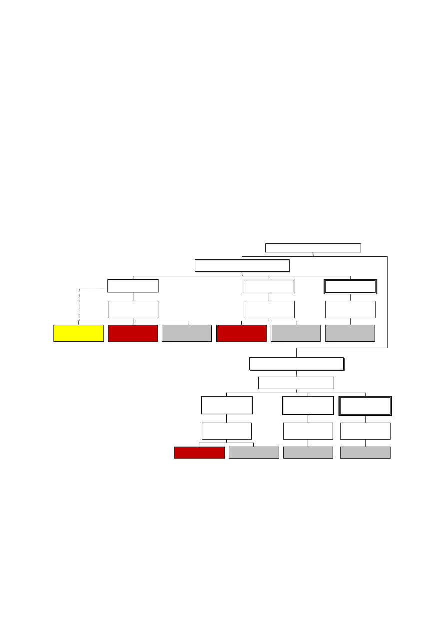
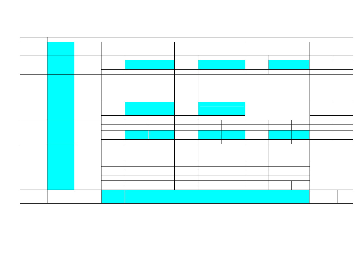
Application of this Part 1-2 of Eurocode 6 with the thermal actions given in EN 1991-
2-2, is illustrated in figure 0.1. For design according to this part, EN 1991-2-2 is
required for the determination of temperature fields in structural elements, or when
using general calculation models for the analysis of the structural response.
T a b u l a r
data
s i m p l e c a l c u l a t i o n
m o d e l s
a d v a n c e d c a l c u l a t i o n
m o d e l s
C a l c u l a t i o n o f
A c t i o n s a t
B o u n d a r i e s
M e m b e r
analysis
( s i m p l e c a l c u l a t i o n
m o d e l s )
a d v a n c e d c a l c u l a t i o n
m o d e l s
C a l c u l a t i o n o f
A c t i o n s e f f e c t s
a t b o u n d a r i e s
a d v a n c e d c a l c u l a t i o n
m o d e l s
s e l e c t i o n o f a c t i o n s
P r e s c r i p t i v e R u l e s
( T h e r m a l a c t i o n s g i v e n b y N o m i n a l f i r e )
( s i m p l e c a l c u l a t i o n
m o d e l s )
a d v a n c e d c a l c u l a t i o n
m o d e l s
C a l c u l a t i o n o f
a c t i o n s
a t b o u n d a r i e s
M e m b e r
a n a l y s i s
a d v a n c e d c a l c u l a t i o n
m o d e l s
C a l c u l a t i o n o f
A c t i o n s e f f e c t s
a t b o u n d a r i e s
a d v a n c e d c a l c u l a t i o n
m o d e l s
s e l e c t i o n o f a c t i o n s
S e l e c t i o n o f
s i m p l e o r a d v a n c e d f i r e m o d e l s
P e r f o r m a n c e-B a s e d C o d e
( P h y s i c a l l y b a s e d t h e r m a l a c t i o n s )
P r o j e c t D e s i g n
a n a l y s i s o f p a r t
o f t h e s t r u c t u r e
a n a l y s i s o f
e n t i r e s t r u c t u r e
a n a l y s i s o f p a r t
of the structure
a n a l y s i s o f
e n t i r e s t r u c t u r e
Figure 0.1 : Design procedures
Where simple calculation models are not available, the Eurocode fire parts give
design solutions in terms of tabular data (based on tests or general calculation
models), which may be used within the specified limits of validity.
It is expected, that design aids based on the calculation models given in ENV 1996-
1-2, will be prepared by interested external organisations.

EN 1996-1-2 is intended for the consideration of:
– code drafting committees;
– clients (e.g. for the formulation of their specific requirements on reliability level);
– designers and contractors;
– public authorities.
EN 1996-1-2 is intended to be used together with EN 1990, EN 1991-1-2 and EN
1996-1-1 for the design of structures.
Numerical values for partial factors and other reliability elements are given as basic values that
provide an acceptable level of reliability. They have been selected assuming that an appropriate level
of workmanship and of quality management applies.
EN1996-1-2 is divided into a main text and a series of annexes.
The main text of EN 1996 together with normative Annex A etc. includes most of the principal
concepts and rules necessary for direct application for structural fire design of
masonry
structures.
National Annex for EN 1996-1-2
This standard gives alternative procedures, values and recommendations for classes
with notes indicating where national choices may have to be made. Therefore the
National Standard implementing EN 1996-1-2 should have a National annex
containing all Nationally Determined Parameters to be used for the design of
buildings and civil engineering works to be constructed in the relevant country.

Section 1. General
1.1 Scope
(1) P This Part 1-2 of EN 1996 deals with the design of masonry structures for the
accidental situation of fire exposure and is intended to be used in conjunction with
EN 1996-1-1, EN 1996-2 and EN 1991-1-2
.
This part 1-2 only identifies differences
from, or supplements to, normal temperature design.
(2) P This document deals only with passive methods of fire protection. Active
methods are not covered.
(3) P This Part 1-2 applies to masonry
structures that, for reasons of general fire
safety, are required to fulfil certain functions when exposed to fire, in terms of:
-
avoiding premature collapse of the structure (load bearing function)
-
limiting fire spread (flame, hot gases, excessive heat) beyond designated areas
(separating function)
(4) P
This Part 1-2 gives principles and application rules (see EN 1991-1-2) for designing structures
for specified requirements in respect of the aforementioned functions and the levels of performance.
(5) P This Part 1-2 applies to structures, or parts of structures, that are within the
scope of EN 1996-1-1 and EN 1996-2 and are designed accordingly. However, it does
not cover reinforced masonry.
(6) P The methods given in this Part 1-2 are applicable to masonry structures, or
parts thereof, that are described in EN 1996-1-1 and EN 1996-2
1)
and are designed
accordingly. This Part deals with the following:
-
non-loadbearing internal walls.
-
non-loadbearing external walls.
-
loadbearing internal walls with separating or non-separating functions.
-
loadbearing external walls with separating or non-separating functions.
Further boundary conditions are defined in Section 3.
1.2 Normative references
The following normative documents contain provisions which, through reference in this text, constitute
provisions of this European Standard. For dated references, subsequent amendments to, or revisions
of, any of these publications do not apply. However, parties to agreements based on this European
Standard are encouraged to investigate the possibility of applying the most recent editions of the
normative documents indicated below. For undated references, the latest edition of the normative
document referred to applies.
EN 771-1
Specification for masonry units
Part 1:Clay masonry units.
1)
ENV 1996-2 is in course of preparation

EN 771-2
Specification for masonry units
Part 2:Calcium silicate masonry
units
EN 771-3
Specification for masonry units
Part 3:Aggregate concrete
masonry units
EN 771-4
Specification for masonry units
Part 4:Aerated concrete
masonry units
EN 771-5
Specification for masonry units
Part 5:Manufactured
stone masonry units
EN 771-13 Methods of tests for masonry units
Part 13: Determination of net
and gross dry
density of masonry units
EN 998-2
Specification for mortar for masonry
Part 2:Masonry mortar.
EN
Plaster and rendering
EN 1363 … Fire resistance: General requirements;
Part 1:General requirements
Part 2:Alternative and additional requirements
ENV 13381 Fire tests on elements of building construction:
Part 2: Test method for determining the contribution to the fire resistance
of structural members: by vertical protective membranes;
Part z: Test method for determining the contribution to the fire resistance
of structural members: by applied protection to masonry structural
elements; ((withdrawn ?))
EN 13501-2
Fire classification of construction products and building elements
Part 2 Classification using data from fire resistance tests, excluding
ventilation services
EN 1991
(Eurocode 1): Basis of design and actions on structures:
Part 1-2:
Actions on structures exposed to fire;
EN 1996
(Eurocode 6): Design of masonry structures:
Part 1.1:
General rules: General rules and rules for buildings;
Part 2: Design, selection of materials and execution of masonry
Part 3: Simplified and simple rules for masonry structures
ISO 1000
SI units.
1.3 Definitions

For the purposes of this Part 1-2 of EN 1996, the definitions of EN 1990 and of EN
1991-1-2 apply with the additional definitions:
Effective cross section:
Cross section of the
member in structure fire design used in the effective cross section method. It is
obtained from the residual cross section by removing parts of the cross section with
assumed zero strength and stiffness.
(EC2)
Fire protection material: Any material or combination of materials applied to a
structural member for the purpose of increasing its fire resistance
Fire wall:
A wall separating two spaces (generally two buildings) that
is designed for fire resistance and structural stability, including resistance to
horizontal loading (Criterion M) such that, in case of fire and failure of the structure
on one side of the wall, fire spread beyond the wall is avoided.
NOTE: In some countries fire wall has been defined as a separating wall between fire compartments
without a requirement for resistance to mechanical impact; the definition above should not be
confused with that more limited one. Fire walls may have to fulfil additional requirements, which
are not given in this part 1-2. They are given in the regulations of each country
Loadbearing wall: Flat, membrane-like component predominantly subjected to
compressive stress, for supporting vertical loads, for example floor loads, and also for
supporting horizontal loads, for example wind loads.
Non-loadbearing wall:
Flat membrane-like building component that is loaded
predominantly only by its dead weight and does not provide bracing for loadbearing
walls; however, it may have to transfer horizontal loads acting on its surface to
loadbearing building components such as walls or floors.
Non-separating wall:
Loadbearing wall exposed to fire on two or more sides.
Normal temperature design: Ultimate limit state design for ambient temperatures
according to Part 1-1 of EN 1992 to 1996 or ENV 1999
Part of structure: isolated part of an entire structure with appropriate support and
boundary conditions.
Residual cross section: Cross section of the original member reduced with the burn
out depth.
Separating wall: wall exposed to fire on one side only.
Structural failure of a wall in the fire situation:
When the wall loses its ability,
calculated in accordance with ENV 1996-1-1, to carry a load up to a resistance of
NRd divided by average Yr after a certain period of time.

F smax = fk /
γ
m
•
γ
f
γ
m
•
γ
f =
1.4 Symbols
For the purpose of this Part 1-2, the following symbols apply
Latin upper case letters
A
m
the surface area of a member per unit length;
A
p
the area of the inner surface of the fire protection material per unit
length of the
member;
E
d,fi
the design effect of actions in the fire situation;
R 30 or R 60,. . ., a member meeting the load bearing criterion for 30, or 60 ..
minutes in standard fire exposure,
E 30 or E 60,. . ., a member meeting the integrity criterion for 30, or 60 ..minutes in
standard fire exposure.
I 30
or I 60,. . ., a member meeting the thermal insulation criterion for 30, or 60 ..
minutes in standard fire exposure.
M 90 or M 120,. . ., a member meeting the mechanical resistance criterion for 90, or
120 .. minutes in standard fire exposure.
Latin lower case letters
c
the specific heat [J/kgK];
c
t
combined web thickness [mm/m]
d
p
the thickness of fire protection material;
f
b
characteristic unit strength [N/mm²]
f
working load that means the actual load on the wall [N/mm²]
h
net,d
the design value of the net heat flux per unit area;
l
the length at 20°C ;
t
the time in fire exposure [minutes];
Greek upper case letters
∆t
the time interval [seconds];
Greek lower case letters

η
fi
the reduction factor for design load level in the fire situation;
θ
the temperature [°C] (cf T temperature [K]);
λ
the thermal conductivity [W/mK];
µ
0
the degree of utilisation at time t = 0.
ρ
is the gross density of the masonry units measured according to EN 772- 13.
1.5 Units
(1)P SI units shall be used in conformity with ISO 1000.
(2)
Supplementary to EN 1996-1-1, the following units are recommended :
-
area
:
m
2
;
-
insulation thickness
:
m;
-
temperature
:
°C;
-
absolute temperature
:
K;
-
temperature difference
:
K;
-
specific heat
:
J/kgK;
-
coefficient of thermal conductivity :
W/mK.

Section 2. Basic principles and rules
2.1 General
(1)P Where mechanical resistance
(R)
in the case of fire is required, structures shall
be designed and constructed in such a way that they maintain their load bearing
function during the relevant fire exposure.
(2)P Where compartmentation is required, the elements forming the boundaries of
the fire compartment, including joints, shall be designed and constructed in such a way
that they maintain their separating function during the relevant fire exposure, i.e.
- no integrity failure
(E)
in order to prevent the passage through it of flames and
hot gases and to prevent the occurrence of flames on the unexposed side
- no insulation failure
(I)
in order to restrict the temperature rise of the unexposed
face to below specified levels.
-
and, when requested, limitation of the thermal radiation
( )
from the unexposed
side.
Note: there is no need to consider the thermal radiation with a unexposed surface temperature below 300 °C (see EN
1361-2 § 8.1)
-
and, when requested, resistance to mechanical impact (M)
(3)P Deformation criteria shall be applied where the means of protection, or the
design criteria for separating elements, require consideration of the deformation of the
load bearing structure.
2.2 Performance requirements
2.2.1 Nominal fire exposure
(1)P Members shall comply with criteria R, E and I as follows:
- separating only (EI):
integrity (criterion E) and
insulation (criterion I)
- load bearing only (R):
mechanical resistance (criterion
R)
- separating and load bearing (REI):
criteria R, E and I
- loadbearing, separating and mechanical impact:
R, E, I and M
- separating and mechanical impact:
E, I and M
(2)
Criterion “R” is assumed to be satisfied where the load bearing function is
maintained during the required time of fire exposure.

(3)
Criterion “I” is assumed to be satisfied where the average temperature rise
over the whole of the non-exposed surface is limited to 140 K, and the maximum
temperature rise at any point of that surface does not exceed 180 K
(
4
)
Criterion “E” is assumed to be satisfied where the passage through the
element of flames and hot gases is prevented.
(
5
) Where a vertical separating element with or without load-bearing function have to
comply with impact resistance requirement (criterion M), the element should resist a
horizontal concentrated load as specified in EN 1363 Part 2.
(
6
) Consideration of the deformation of the load bearing structure is not necessary in
the following cases
-
the efficiency of the means of protection has been evaluated according to 3.3.3,
-
the separating elements have to fulfil requirements according to a nominal fire
exposure.
2.2.2 Parametric fire exposure
(1) The load-bearing function is ensured when collapse is prevented during the
complete duration of the fire including the decay phase or during a required period of
time.
(2) The separating function with respect to insulation is ensured when
-
the average temperature rise over the whole of the non-exposed surface is
limited to 140 K, and the maximum temperature rise of that surface does not
exceed 180 K at the time of the maximum gas temperature,
-
and the average temperature rise over the whole of the non-exposed surface is
limited to 180 K, and the maximum temperature rise of that surface does not
exceed 220 K during the decay phase of the fire or up to a required period of
time.
2.3 Actions
(1)P The thermal and mechanical actions shall be taken from EN 1991-1-2.
(2)
In addition to EN 1991-1-2, the emissivity related to the surface material of
members should be equal to 0.
xx

2.3 Design values of material properties
(1)P Design values of mechanical (strength and deformation) material properties X
d,fi
are defined as follows:
X
d,fi
=
k
θ
X
k
/
γ
M,fi
(2.1c)
where:
X
k
is
the characteristic value of a strength or deformation property
(generally
f
k
or E
k
) for normal temperature design to EN 199
6
-1-1;
k
θ
is
the reduction factor for a strength or deformation property (X
k,
θ
/
X
k
) ,
dependent on the material temperature, see
Annex D
;
γ
M,fi
is
the partial safety factor for the relevant material property, for the
fire
situation.
(2)P Design values of thermal material properties X
d,fi
are defined as follows:
- if an increase of the property is favourable for safety:
X
d,fi
=
X
k,
θ
/
γ
M,fi
(2.1a)
- if an increase of the property is unfavourable for safety:
X
d,fi
=
γ
M,fi
X
k,
θ
(2.1b)
where:
X
k,
θ
is
the value of a material property in fire design, generally dependent
on
the material temperature, see section 3;
γ
M,fi
is
the partial safety factor for the relevant material property, for the
fire
situation.
____________________________________________________________________________
_______
NOTE: For thermal properties of masonry the recommended value of partial safety factor for the fire situation is:
γ
M,fi
=
1,0
For mechanical properties of masonry, the recommended value of partial safety factor for the fire situation
is:

γ
M,fi
=
1,0
2.4 Assessment methods
2.4.1 General
(1)P The model of the structural system adopted for design in the fire situation shall
reflect the expected performance of the structure in fire.
(2)P The analysis for the fire situation may be carried out using one of the following:
- member analysis, see 2.4.2.
- analysis of part of the structure, see 2.4.3;
- global structural analysis, see 2.4.4
Note: Thermal expansion may cause large action effect remote from the fire source
(3)P It shall be verified for the relevant duration of fire exposure that
E
fi,d
≤
R
fi,d
(2.7)
where
E
fi,d
is the design effect of actions for the fire situation, determined in
accordance with
EN 1991-2-2, including effects of thermal expansions and deformations
R
fi,d
is the corresponding design resistance in fire situation.
(4)
For verifying standard fire resistance requirements, a member analysis is
sufficient
(5)
Where application rules given in this Part 1-2 are valid only for the standard
temperature-time curve, this is identified in the relevant clauses
(6)
Tabulated data given in 3.5 are based on the standard temperature-time curve.
(7)P As an alternative to design by calculation, fire design may be based on the
results of fire tests, or on fire tests in combination with calculations, see EN 1990
clause 5.2 .

2.4.2 Member analysis
(1)
The restraint conditions at supports and ends of member, applicable at time t = 0, are
assumed to remain unchanged throughout the fire exposure.
(2)
As an alternative to carrying out a structural analysis for the fire situation at time
t = 0, the reactions at supports and internal forces and moments may be obtained from
a structural analysis for normal temperature design by using:
E
fi,d
=
η
fi
E
d
(2.3)
where:
E
d
is the design value of the corresponding force or moment
for normal temperature design, for a fundamental combination of
actions (see EN 1990);
η
fi
is the reduction factor for the design load level for the fire
situation.
(3)
The reduction factor for the design load level for the fire situation
η
fi
for load
combination (6.10) in EN 1990 is given by:
η
fi
=
Q
+
G
Q
+
G
k,1
Q,1
k
G
k,1
1,1
k
GA
γ
γ
ψ
γ
1
(2.4)
or the lower of the two following expressions for load combinations (6.10)a and
(6.10b) in EN 1990:
η
fi
=
Q
+
G
Q
+
G
1,1
k,1
1
,
0
Q,1
k
G
k,1
k
GA
ψ
γ
γ
ψ
γ
(2.4a)
η
fi
=
Q
+
G
Q
+
G
1,1
k,1
Q,1
k
G
k,1
k
GA
γ
ξγ
ψ
γ
(2.4b)
where:
Q
k,1
is
the principal variable load;
γ
GA
is
the partial factor for permanent actions in accidental design
situations;
ψ
1,1
is
the combination factor for frequent values, see table xx in
EN1990
NOTE: Regarding equation (2.4), an example of the variation of the reduction factor
η
fi
versus the load ratio
Q
k,1
/G
k
for different values of the combination factor
ψ
1,1
are shown in figure 2.1 with the following
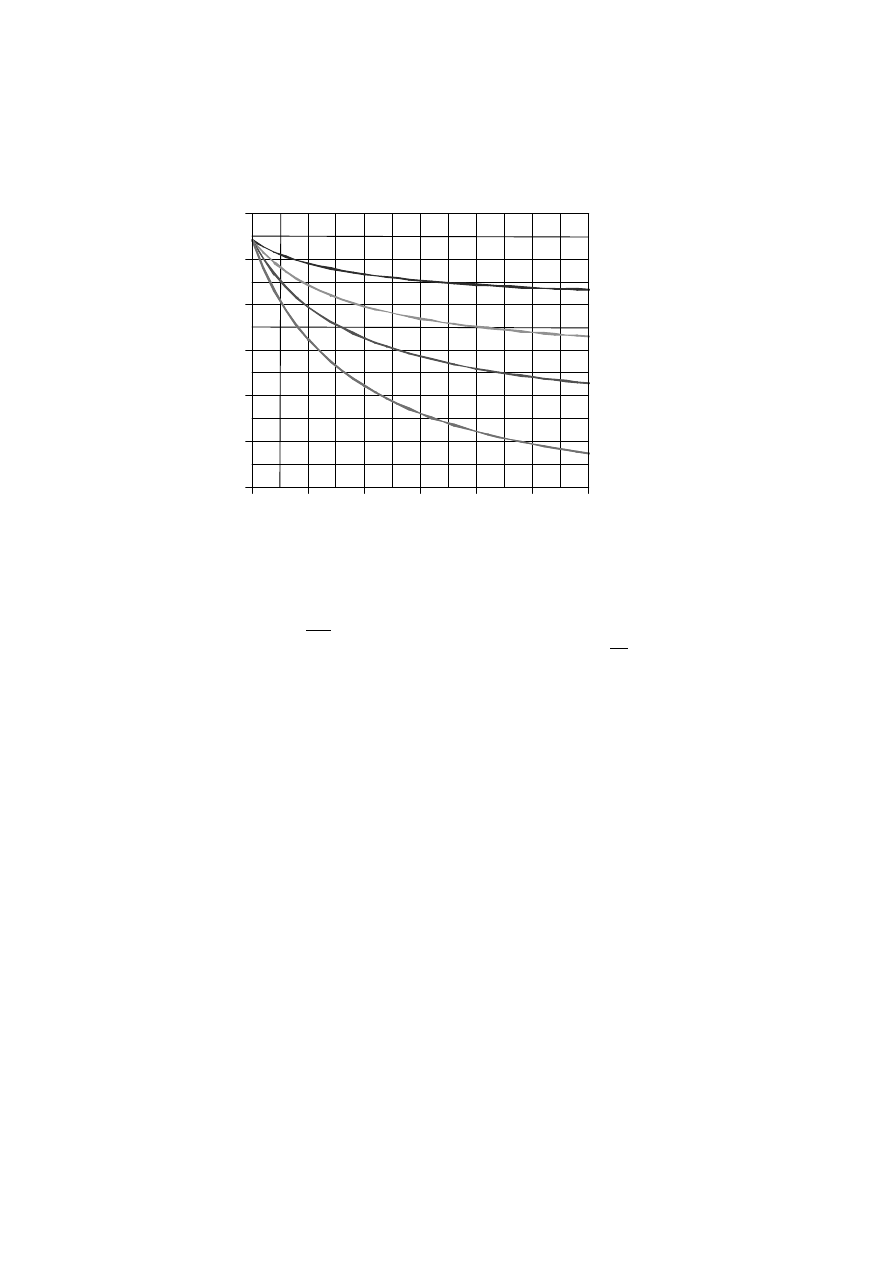
assumptions:
γ
GA
= 1,0,
γ
G
= 1,35 and
γ
Q
= 1,5. Partial factors are specified in the relevant National
annexes of EN 1990.Note that equations (2.4a) and (2.4b) give slightly higher values.
3,0
0,0
0,5
1,0
1,5
2,0
2,5
0,2
0,3
0,4
0,5
0,6
0,7
0,8
Q / G
k,1 k
_η
fi
1,1
_ψ
= 0,7
1,1
_ψ
= 0,9
1,1
_ψ
= 0,5
1,1
_ψ
= 0,2
1
Figure 2.1: Variation of the reduction factor
η
fi
with the load ratio Q
k,1
/
G
k
Note
As a simplification
η
fi
= 0,65 may be used, except for load category E as given in ENV 1991-2.1 (areas
susceptible to accumulation of goods, including access areas) for which a value of 0,7 should be used.
(4)
Only the effects of thermal deformations resulting from thermal gradients across the cross-
section need be considered. The effects of axial or in-plain thermal expansions may be neglected.
(5)
Tabulated data, simplified or general calculation methods given in 4.2, 4.3 and 4.4 respectively
are suitable for verifying members under fire conditions.
2.4.3 Analysis of part of the structure
(1)P
The part of the structure to be analysed should be specified on the basis of the potential
thermal expansions and deformations such, that their interaction with other parts of the structure can
be approximated by time-independent support and boundary conditions during fire exposure.
(2)
Within the part of the structure to be analysed, the relevant failure mode in fire exposure, the
temperature-dependent material properties and member stiffnesses, effects of thermal expansions
and deformations (indirect fire actions) shall be taken into account
(3)
The restraint conditions at supports and forces and moments at boundaries of part of the
structure, applicable at time t = 0, are assumed to remain unchanged throughout the fire exposure
2.4.4 Global structural analysis

(1)P
When global structural analysis for the fire situation is carried out, the relevant failure mode in
fire exposure, the temperature-dependent material properties and member stiffnesses, effects of
thermal expansions and deformations (indirect fire actions) shall be taken into account.

3
Fire resistance of masonry walls
3.1
General information on the design of walls
3.1.1 General
(1)
This Part applies to walls designed and built in accordance with Principles and
Application Rules of EN1996-1-1, EN 1996-2 and ENV 1996-3. This part is also valid
for non-loadbearing walls.
3.1.2 Wall types by function
(1)
For fire protection, a distinction is made between non-loadbearing walls and
loadbearing walls and between separating walls and non-separating walls.
(2)
Examples of separating walls are walls along escape ways, walls of stair wells, or compartment
walls. They serve to prevent fire propagating from one place to another. They are exposed to fire on
one side only.
(3)
Examples of non-separating loadbearing walls are walls within a fire
compartment; they are loadbearing, but are subjected to fire on two or more sides.
(4)
External walls may be separating walls, or non-separating walls as required.
External separating walls less than 1,0 m in length should be treated as non-
separating walls.
(5)
Wall areas comprising lintels above openings must fulfil at least the same fire
resistance class as the wall.
(6)
Fire walls are separating walls that additionally are required to resist
mechanical impact, for example to separate buildings or fire compartments. There
are additional requirements relating to:
-
non-combustible materials
-
constructional detailing for preventing fire spread
-
thermal reaction or expansion of adjacent construction situated close to the
fire wall may not effect the fire wall
-
stiffening. Where stiffenings such as cross walls, floors, beams, columns or
frames, these must fulfil at least the same fire resistance class as the fire wall.
Columns and beams made of steel , which are situated directly in front of a fire wall may have
to fulfil additional requirements.
It is possible to place stiffenings without fire resistance on both sides of the fire wall, if it is
assessed that the failure of the stiffenings on one side of the fire wall does not lead to a
failureof the fire wall.
NOTE: See note for definition of fire walls and impact, chapter 1.3.
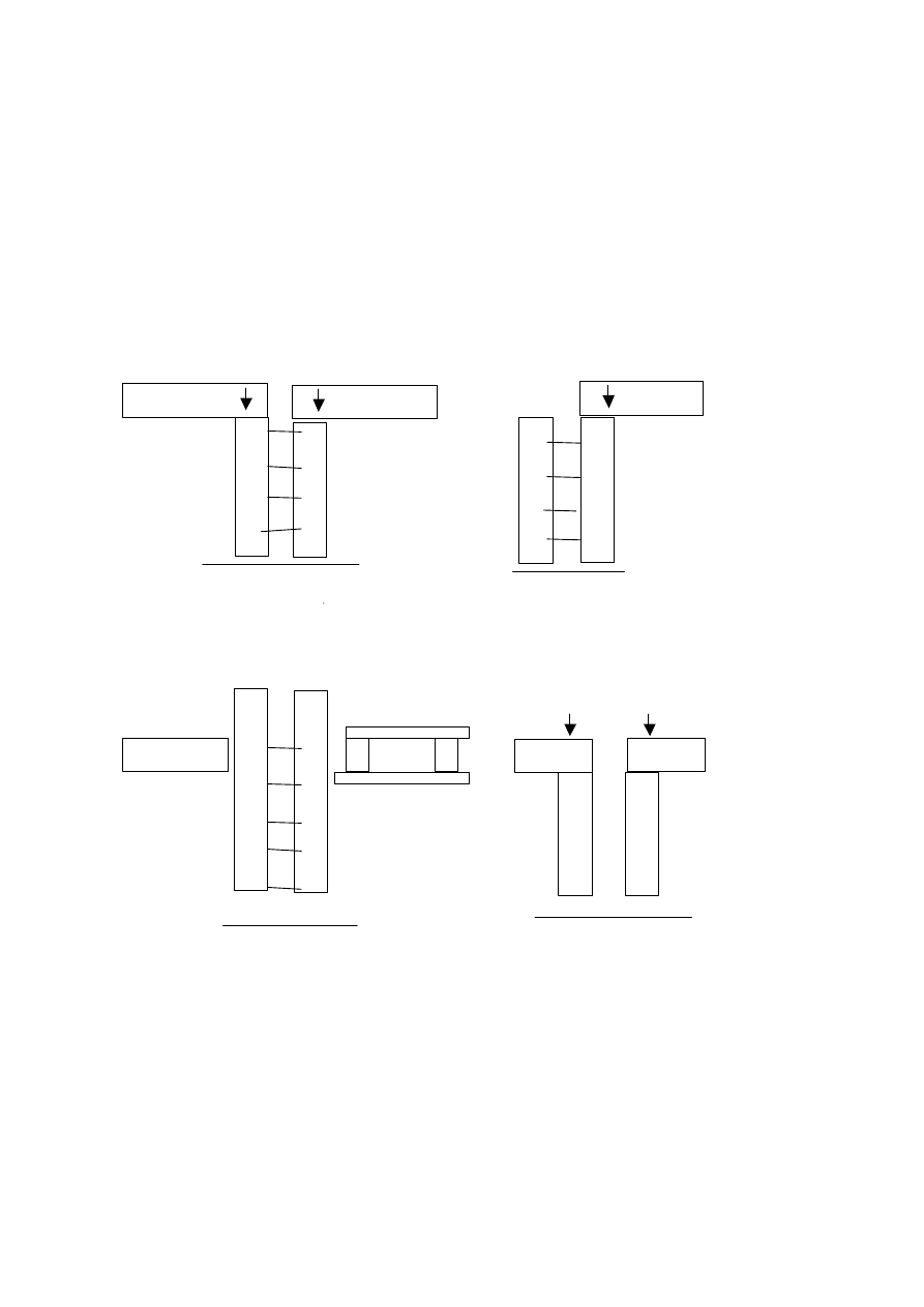
3.1.3 Cavity walls and untied walls comprising independing leaves
(1)
The fire resistance of a cavity wall depends upon whether one or both leaves of
the wall are loaded. When both leaves are loadbearing and carry approximately
equal loads, the fire resistance of a cavity wall with leaves of approximately equal
thickness is defined as the fire resistance of an equivalent single leaf wall of
thickness equal to the sum of the thicknesses of the two leaves, see
figure 1.1
.
walls tied
wall ties
or no ties
or
bed joint reinforcement
cavity unfilled or
filled with thermal insulation
or partially filled
figure1.1:
cavity wall
figure 1.2:
cavity wall
walls untied
figure 1.3
cavity wall
figure 1.4:
double leaf wall
figure 1:
Explanation of cavity walls and double leaf walls
(2)
When only one leaf of a cavity wall is loadbearing, the resistance of the wall is
usually enhanced over the fire resistance achieved for the loadbearing leaf when
considered to act as a single leaf wall, see
figure 1.2.
(3)
The fire resistance of a cavity wall comprising two non-loadbearing leaves may be taken as the

sum of the fire resistances of the individual leaves with a limit to a maximum of 240 min when fire
resistance is determined by this method, see
figure1.3.
(4)
For untied walls comprising independing leafs the fire resistance of the wall is
determined by reference to the appropiate table for single leaf walls – loadbearing or
nonloadbearing, see
figure 1.4
.
3.1.4 Junctions, joints
(1)
This Part applies to walls that extend from one floor to the next floor or to the
roof; it is assumed that those floors or the roof provide lateral support to the top and
bottom of the wall, unless its stability under normal function is achieved by other
means, for example buttresses or special ties.
(2)P Joints, including movement joints, in walls or between walls and other fire
separating members shall be designed and constructed so as to meet the fire
resistance requirement of the wall.
(3)P Where insulating layers are required in movement joints, they shall consist of
mineral based materials having a melting point of not less than 1.000
0
C. Any joints
shall be tightly sealed so that movements of the wall shall not adversely effect the fire
resistance. If other materials are to be used, it shall be shown by test that they will
meet criteria E and I (see EN 1366: Part 4).
(4)
Connections of non-loadbearing masonry walls may be built according to
EN 1996 - 2 or to the examples given in annex C of this part, figures 1 and 2.
[[EN 1996- 2 or -3 needs to be checked, when draft is presented]]
(5)
Connections of loadbearing masonry walls may be built according to EN 1996
- 2 or to the examples given in annex C of this part figures 3 and 4.
[[EN 1996 - 2 needs to be checked, when draft is presented]]
(6)
Connections of fire walls to other structures
Connections with no static requirements can be built according to annex C of this part
figures 1 and 2 (examples).
Connections to reinforced, unreinforced concrete and masonry structures which have
to fulfil static requirements (connections which have to fulfil the mechanic impact
according to EN 1363-2) must be built with joints that filled completely with mortar
according to EN XXX 998-2 or concrete according to EN
XXX
or according to the

figures 3, 4, and 5 given in annex C of this part (examples).
Method of connecting the fire wall may effect the fire resistance.
3.1.5 Fixtures, pipes and cables
(1)
Recesses and chases, that are permitted in EN 1996-1-1 to be included in loadbearing walls
without the need for separate calculation, can be assumed not to reduce the period of fire resistance
given in the tables referred to in 3.5.
(2)
For non-loadbearing walls, vertical chases and recesses should leave at least
2/3 of the required minimum thickness of the wall or at least 60 mm, including any
integrally applied fire resistance finishes such as plaster.
(3)
Horizontal and inclined chases and recesses in non-loadbearing walls should
leave at least 5/6 of the required minimum thickness of the wall or at least 60 mm,
including any integrally applied fire resistant finishes such as plaster.They should not
be positioned within the middle one-third height of the wall. The width of individual
chases and recesses in non-loadbearing walls should be not greater than twice the
required minimum thickness of the wall, including any integrally applied fire resistant
finishes such as plaster.
(4)
If the above rules for recesses and chases are not followed test according to
EN 1364 are necessary.
(5)
Individual cables may pass through holes sealed with mortar. Non-combustible
pipes up to 100 mm diameter may pass through holes, sealed with mortar (see
footnote), if the effects of heat conduction through the pipes is not sufficient to
infringe the criterion I and E and elongation.
(6)
Groups of cables and pipes of combustible material, or individual cables in
holes not sealed with mortar, may pass through walls only if
-
the method of sealing the penetration has been evaluated by testing according
to EN 1366: Part 3
4)
-
follow recognised national guidance.
3.2
Materials for use in masonry walls
3.2.1 Units
(1)
The Tables referred to in 3.5 apply to masonry built with units that comply with
EN 771-1,2,3 and 4. Limitations as to strength and density of units are stated in the
4)
If materials other than mortar are approved by CEN Standards, they may be substitutes

Tables. If units not covered by EN 771-1, 2, 3, 4 or units according to EN 771 - 5, are
to be used, evaluation by testing should be carried out.
(2)P Masonry units shall be grouped as Group 1, 2 or 3 as given in table 3.1
(3)
For the purposes of the tables referred to in 3.5 some thicknesses of walls are
further specified to be built in solid units; such units should not contain any
perforations, but they may contain indentations, for example frogs, grip holes or
grooves in the bed face, that will be filled with mortar in the finished wall. In the case
of frogged units the gross volume of the frog should not exceed 20 %.
3.2.2 Mortar
(1)
The tables referred to in 3.5 apply to masonry built with general purpose,
lightweight, or thin layer mortars complying with EN 998-2 or 1996-1-1.
except that
the mortar joint thickness is limited to a maximum of 3 mm when mortars based on
organic binders are used.
3.2.3 Rendering and plastering mortar
(1)
The fire resistance of masonry walls may be increased by the use of the
following mortar of at least 10 mm thickness:
-
plaster type L-G according to EN 998-1 or
-
gypsum pre
mixed
plaster according to EN XXX
-
plaster type LW or T according to EN 998-1
(2)
The bond between plaster and masonry for fire is only effectiv, if the
requirements of EN 998
–
1 are fullfiled.
Table 3.1: Requirements for grouping of masonry units based on fire aspects.
Group of masonry units
1
2
3
((Wärmedämm-
ziegel))
4
((Füllziegel))
5
((Langloch-
ziegel))
Volume of holes
(% of the gross volume)
≤
25
(see note 1)
> 25-55 for clay
units
> 25-60 for
concrete
aggregate units
≤
70
Limited by area
(see note 3)
(see note 3)
horizontal holes
Volume of any hole
(% of the gross volume)
≤
12,5
≤
12,5 for clay
units
< 25 for concrete
aggregate units
each of multiple
holes < 10%
single holes
< 50 %
???
Minimum thickness of
material between and
around holes (mm)
No requirement
web shell
clay 6 10
concrete 20 20
cal-sil 10 15
web shell
clay 6 10
web shell
clay 6 10
web shell
clay 6 10
Combined thickness c
t
(% of the overall width or
(mm/m)
(see note 4)
> 37,5 %
≥
20 or > 30 %
> 120 mm/m
> 100 mm/m
no requirement
1. Holes may consist of formed vertical holes through the units or frogs or recesses.
2. Further conditions according the unit strength, the density and the loading are given in the tables 3.2 - 3.6.
3. Holes may only consist of formed vertical holes through the unit or recesses.
4. The combined thickness is the thickness of the webs and shells, measured horizontally across the unit at right angles to
the face of the wall.
Grouping of masonry units
solid units
calcium
silicate
1
2
3 (thermal insulating units)
4 (units for mortar or concrete infill)
5 (horizontally perforated
units)
clay
25 < x
≤
55
clay
55 < x
≤
70
clay
25 < x
≤
70
clay
25 < x
≤
70
calcium
silicate
25 < x
≤
55
calcium
silicate
calcium
silicate
calcium
silicate
volume of
holes (% of the
gross volume)
≤
5
≤
25
concrete
25 < x
≤
60
concrete
concrete
concrete
clay
each of multiple holes
≤
1 %
gripholes up to a total of
12,5%
clay
each of multiple holes
≤
1
%
gripholes up to a total of
12,5%
clay
each of
multiple
holes
≤
12,5
%
single hole
≤
50%
calcium
silicate
each of multiple holes
≤
15 %
gripholes up to a total of
30 %
calcium
silicate
calcium
silicate
Volume of any
hole (% of the
gross volume)
≤
2,5
≤
12,5
concrete
concrete
no requirement
concrete
web
shell
web
shell
web
shell
web or shell
clay
5
8
clay
3
6
clay
14
20
clay
8
calcium
silicate
5
10
calcium
silicate
calcium
silicate
calcium
silicate
Minimum
thickness in
and around
holes (mm)
no requirement
concrete
15
15
concrete
concrete
concrete
minimum
thickness of
any web or
shell
minimum number of webs
and shells per m (length or
thickness of the wall)
minimum
thickness of
any web or
shell
minimum number of webs
and shells per m (length or
thickness of the wall)
minimum
thickness of
any web or
shell
minimum number of
webs and shells per m
(length or thickness of
the wall)
5
30
5
20
14
6
8
20
8
15
10
16
10
12
15
11
15
8
20
8
Regularity
criterion
no requirement
30
6
no requirement
calcium
silicate
the minimum of webs and shells (length or thickness of the wall)
≥
150 mm/m
concrete 200 mm/m

3.3
Additional requirements related to masonry walls
(1)P Any supporting or stiffening part of a structure shall have at least the same fire
resistance as the structure being supported or stiffened.
(2)
Flammable thin damp proof materials incorporated into a wall may be ignored
in assessing fire resistance.
(3)
Perforated masonry units should not be laid so that the perforations are at right
angles to the face of the wall, i.e. the wall should not be penetrated by the masonry
units perforations.
(4)
Unplastered Masonry having unfilled vertical joints less than 5 mm wide, made with units that
are designed to be used and accepted in that way, (i.e. high precision dimension or tonge and groove
masonry units) may be treated as being within the tables referred to in 3.5 if plaster of 1 mm thickness
is used on at least on one side. The fire resistance periods are those given by the values without ().
These values are also valid for walls having sand-cement rendered finish.
(5)P The tables referred to in 3.5 shall not be used for walls either having a height
to thickness ratio greater than the following:
-
Loadbearing
general purpose mortar
27
light weight mortar
27
thin layer mortar
30
-
Non-loadbearing
40
or exceeding the relevant size limits given in EN 1996-1-1 or EN 1996-2.
Loadbearing walls should additionally meet all regulatory requirements for structural
stability in respect of the individual and combined actions and should be designed in
accordance with EN 1996-1-1 or ENV 1996-3.
Remark
just for information
:
Class
I
II
III
IV
comments from (UK)
(Finland)
(Germany)
(Netherlands)
-
Loadbearing
27
26
25
30
-
Non-loadbearing
40
26
40
40
(6)
When rendering or plaster is required for enhance the fire resistance of two leaf
walls an additional masonry leaf or masonry cladding can be used instead. For cavity
and two
double
leaf walls rendering or plaster is only needed on the outside of the
leafs - not between the two leafs.
(7)
If thermal insulation systems made of insulation and plaster according to
EN
XXX
are used on single leaf external walls

-
insulation layers made of combustible materials do not enhance fire resistance,
-
insulation layers made of non-combustible materials, e.g. mineral wool or
foamglas, can be used instead of the 10 mm rendering or plaster.
3.4
Assessment by testing
(1)
For all types of masonry walls the fire resistance may be obtained, using the
test methods listed in Annex A.
3.5
Assessment by tabulated data
(1)
Assessment for masonry walls may be made by the following tabulated data giving minimum
thicknesses of masonry for stated periods of fire resistance, made with units of
-
clay complying with EN 771-1,
-
calcium silicate complying with EN 771-2,
-
aggregate concrete complying with EN 771-3,
-
autoclaved aerated concrete, complying with EN 771-4.
.
(2)
Masonry walls comprising natural stone and manufactored units are not
covered by the tabulated data.
(3)
In these tables, the thickness referred to should be of the masonry itself,
excluding finishes, if any. The first row is for walls without an applied finish or walls
having a sand-cement rendered finish or thin rendering ((Spachtelputz)). Values in
brackets () are for walls having an applied finish of rendering or plaster according to
3.2.3 of minimum thickness 10mm on both sides of the wall.
(4)
In these tables, the minimum thickness of a wall for fire resistance purposes is
given. The thickness required from consideration of EN 1996-1-1, or other
requirements, for example sound performance, are not taken into account.
(5)
The values that apply to loadbearing walls are stated to cover, as appropriate,
a load up to characteristic compressive strength or less depending in the type of unit.
It is the actual load (working load) that is possible to put on the wall.
Note: As EN1996-1-1 was not ready when discussion the tables this way of fixing the load was the only way, because
the fire behaviour of masonry depends mainly on the percentage of load depending on the type of unit and unit
strength.
[
for consideration after finishing the tables
]
(6)
The use of Tables 1.3, 2.3, 3.3, 4.3, is limited to walls of length greater than 1,0 m. For walls
less than 1,0 m in length, Tables 1.4, 2.4, 3.4, 4.4, should be used.
Table 1.1:
Fire resistance classification for masonary wall made of
Clay units
complying with EN 771-1
Criterion EI non-loadbearing
Minimum wall thickness (mm) for
fire resistance classification (min)
EI - separating non-loadbearing
row
num
ber
material
properties
gross density
ρ
[kg/m³]
15
20
30
45
60
90
120
180
240
1
1.1
1.2
clay units
group 1 -
3
mortar :
general purpose,
thin layer,
lightweight
500 <
ρ
< 2.400
60
(50)
60
(50)
60
(50)
100
(50)
100
(60)
100
(80)
100
(100)
170
(130)
200
(170)
Table 1.2:
Fire resistance classification of masonary walls made of
Clay units
conforming To EN 771-1 and EN 771-X
Criterion REI - Separating loadbearing single-leaf walls
Minimum wall thickness (mm) for
fire resistance classification (min)
REI - separating loadbearing
row
num
ber
material properties
unit strength f
b
[N/mm²]
gross density
ρ
[kg/m³]
combined thickness ct
[mm/m]
30
45
60
90
120
180
240
1
group 1
mortar:
general purpose, thin layer
5< f
b
<15
800 <
ρ
< 2.400
100 %
f < 2 N/mm²
100
(90)
100
(100)
100
(100)
170
(100)
200
(170)
200
(170)
60 %
f < 1,5 N/mm²
100
(90)
100
(100)
100
(100)
140
(100)
170
(140)
200
(170)
1.1
1.1.1
1.1.2
1.1.3
f < 0,75 N/mm²
100
(90)
100
(90)
100
(100)
140
(100)
170
(140)
200
(170)
15 < f
b
< 100
1.000 <
ρ
< 2.400
100 %
f < 5 N/mm²
100
(90)
100
(90)
100
(100)
140
(100)
200
(140)
200
(170)
1.2
1.2.1
1.2.2
60 %
f < 3 N/mm²
90
(90)
100
(90)
100
(90)
100
(100)
170
(140)
200
(170)
5 < f
b
< 35
500 <
ρ
< 800
100 %
f < 2,25 N/mm²
100
(100)
200
(170)
240
(240)
365
(300)
365
(365)
1.3
1.3.1
1.3.2
60 %
f < 1,25 N/mm²
100
(100)
170
(140)
240
(170)
365
(300)
365
(300)
2
group 2
mortar:
general purpose, thin layer
7,5 < f
b
< 15
800 <
ρ
< 2.200
ct > 250
100 %
f < 2,75 N/mm²
100
(100)
100
(100)
170
(100)
240
(140)
240
(170)
2.1
2.1.1
2.1.2
60 %
f < 1,75 N/mm²
100
(100)
100
(100)
140
(100)
170
(100)
240
(140)
15 < f
b
< 35
800 <
ρ
< 2.200
ct > 250
100 %
f < 4,25N/mm²
100
(100)
100
(100)
170
(100)
240
(140)
240
(170)
2.2
2.2.1
2.2.2
60 %
f < 2,5N/mm²
100
(100)
100
(100)
140
(100)
170
(100)
240
(140)
mortar: and lightweight
5 < f
b
< 10
700 <
ρ
< 800
ct > 250
100 %
f < 2,25N/mm²
(100)
(100)
(100)
(140)
(170)
2.3
2.3.1
2.3.2
60 %
f < 1,25 N/mm²
(100)
(100)
(100)
(100)
(140)
mortar: and lightweight
10 < f
b
< 25
700 <
ρ
< 800
ct > 250
100 %
f < 3,25N/mm²
(100)
(100)
(100)
(140)
(170)
2.4
2.4.1
2.4.2
60 %
f < 2 N/mm²
(100)
(100)
(100)
(100)
(140)
Minimum wall thickness (mm) for
fire resistance classification (min)
REI - separating loadbearing
row
num
ber
material properties
unit strength f
b
[N/mm²]
gross density
ρ
[kg/m³]
combined thickness ct
[mm/m]
30
45
60
90
120
180
240
mortar: and lightweight
5 < f
b
< 10
500 <
ρ
< 900
160 < ct > 250
100 %
f < 2,25 N/mm²
(100)
(170)
(240)
(300)
(365)
2.5
2.5.1
2.5.2
2.5.3
2.5.4
60 %
f < 1,25 N/mm²
(100)
(140)
(170)
(300)
(300)
10 < f
b
< 25
500 <
ρ
< 900
160 < ct > 250
100 %
f < 3,25 N/mm²
(100)
(170)
(240)
(300)
(365)
2.6
2.6.1
2.6.2
2.6.3
2.6.4
60 %
f < 2 N/mm²
(100)
(140)
(170)
(300)
(300)
group 3
mortar: general purpose and
lightweight and thin layer
vertical perforation
5 < f
b
< 35
500 <
ρ
< 1.200
ct > 120
100 %
f < 2 N/mm²
(100)
(240)
(300)
(365)
(425)
3
3.1.1
3.1.2
3.1.3
3.1.4
60 %
f < 1,25 N/mm²
(100
(170)
(240)
(300)
(365)
group 4
mortar: general purpose and
thin layer
vertical perforation
10 < f
b
< 35
500 <
ρ
< 1.200
ct > 100
σ
= 100 %
< 3,25 N/mm²
100
(100)
100
(100)
170
(100)
240
(140)
240
(170)
4
4.1.1
4.1.2
4.1.3
4.1.4
σ
= 60 %
< 2 N/mm²
100
(100)
100
(100)
140
(100)
170
(100)
240
(140)
group 5
mortar: general purpose and
lightweight and thin layer
horizontal perforation
5 < f
b
< 35
500 <
ρ
< 1.200
100 %
f < 2,25 N/mm²
(100)
(240)
(300)
(365)
(425)
5
5.1.1
5.1.2
5.1.3
5.1.4
60 %
f < 1,25 N/mm²
(100
(170)
(240)
(300)
(365)
Table 1.3:
Fire resistance classification for masonary wall made of
Clay units
comforming with EN 771-1 and EN 771-X
Criterion R - Non-separating loadbearing single-leaf walls - length > 1,0 m
Minimum wall thickness (mm) for
fire resistance classification (min)
R - non-separating loadbearing
row
num
ber
material properties
unit strength f
b
[N/mm²]
gross density
ρ
[kg/m³]
combined thickness ct
[mm/m]
30
45
60
90
120
180
240
1
group 1
mortar:
general purpose, thin layer
5< f
b
<15
800 <
ρ
< 2.400
100 %
f < 2 N/mm²
100
(100)
100
(100)
240
(100)
365
(170)
490
(240)
60 %
f < 1,5 N/mm²
100
(100)
100
(100)
170
(100)
240
(100)
300
(200)
1.1
1.1.1
1.1.2
1.1.3
1.1.4
f < 0,75 N/mm²
100
(100)
100
(100)
170
(100)
240
(100)
300
(200)
15 < f
b
< 100
1.000 <
ρ
< 2.400
100 %
f < 5 N/mm²
100
(100)
100
(100)
240
(100)
365
(170)
490
(240)
1.2
1.2.1
1.2.2
1.2.3
1.2.4
60 %
f < 3 N/mm²
100
(100)
100
(100)
170
(100)
240
(100)
300
(200)
5 < f
b
< 35
500 <
ρ
< 800
100 %
f < 2,25 N/mm²
100
(100)
200
(170)
240
(240)
365
(300)
365
(365)
1.3
1.3.1
1.3.2
1.3.3
1.3.4
60 %
f < 1,25 N/mm²
100
(100)
170
(140)
240
(170)
365
(300)
365
(300)
group 2
mortar:
general purpose, thin layer
7,5 < f
b
< 15
800 <
ρ
< 2.200
ct > 250
100 %
f < 2,75 N/mm²
100
(100)
100
(100)
240
(100)
365
(170)
490
(240)
2
2.1
2.1.1
2.1.2
2.1.3
2.1.4
60 %
f < 1,75 N/mm²
100
(100)
100
(100)
170
(100)
240
(100)
300
(200)
f
b
> 15– 35
800 <
ρ
< 2.200
ct > 250
100 %
f < 4,25N/mm²
100
(100)
100
(100)
240
(100)
365
(170)
490
(240)
2.2
2.2.1
2.2.2
2.2.3
2.2.4
60 %
f < 2,5N/mm²
100
(100)
100
(100)
170
(100)
240
(100)
300
(200)
mortar: and lightweight
5 < f
b
< 10
700 <
ρ
< 800
ct > 250
100 %
f < 2,25N/mm²
(100)
(100)
(100)
(170)
(240)
2.3
2.3.1
2.3.2
2.3.3
2.3.4
60 %
f < 1,25 N/mm²
(100)
(100)
(100)
(100)
(200)
mortar: and lightweight
10 < f
b
< 25
700 <
ρ
< 800
ct > 250
100 %
f < 3,25N/mm²
(100)
(100)
(100)
(170)
(240)
2.4
2.4.1
2.4.2
2.4.3
2.4.4
60 %
f < 2 N/mm²
(100)
(100)
(100)
(100)
(200)
Minimum wall thickness (mm) for
fire resistance classification (min)
R - non-separating loadbearing
row
num
ber
material properties
unit strength f
b
[N/mm²]
gross density
ρ
[kg/m³]
combined thickness ct
[mm/m]
30
45
60
90
120
180
240
mortar: and lightweight
5 < f
b
< 10
500 <
ρ
< 900
160 < ct > 250
100 %
f < 2,25 N/mm²
(240)
(240)
(240)
(300)
(365)
2.5
2.5.1
2.5.2
2.5.3
2.5.4
60 %
f < 1,25 N/mm²
(170)
(170)
(240)
(240)
(300)
10 < f
b
< 25
500 <
ρ
< 900
160 < ct > 250
100 %
f < 3,25 N/mm²
(240)
(240)
(240)
(300)
(365)
2.6
2.6.1
2.6.2
2.6.3
2.6.4
60 %
f < 2 N/mm²
(170)
(170)
(240)
(240)
(300)
group 3
mortar: general purpose and
lightweight and thin layer
vertical perforation
5 < f
b
< 35
500 <
ρ
< 1.200
ct > 120
100 %
f < 2 N/mm²
(100)
(240)
(300)
(365)
(425)
3
3.1.1
3.1.2
3.1.3
3.1.4
60 %
f < 1,25 N/mm²
(100)
(170)
(240)
(300)
(365)
group 4
mortar: general purpose and
thin layer
vertical perforation
10 < f
b
< 35
500 <
ρ
< 1.200
ct > 100
σ
= 100 %
< 3,25 N/mm²
100
(100)
100
(100)
240
(100)
365
(170)
490
(240)
4
4.1.1
4.1.2
4.1.3
4.1.4
σ
= 60 %
< 2 N/mm²
100
(100)
100
(100)
170
(100)
240
(100)
300
(200)
group 5
mortar: general purpose and
lightweight and thin layer
horizontal perforation
5 < f
b
< 35
500 <
ρ
< 1.200
100 %
f < 2,25 N/mm²
(100)
(240)
(300)
(365)
(425)
5
5.1.1
5.1.2
5.1.3
5.1.4
60 %
f < 1,25 N/mm²
(100)
(170)
(240)
(300)
(365)
Table 1.4:
Fire resistance classificationof masonary walls made of
Clay units
conforming to EN 771-1 and EN 771-X
Criterion R Non-separating leadbearing single-leaf columns – length < 1,0 m
Minimum wall thickness (mm) for
fire resistance classification (min)
R - nonseparating loadbearing column
row
numb
er
material
properties
unit strength f
b
[N/mm²]
gross density
ρ
[kg/m³]
combined thickness ct
[mm/m]
mini
mum
wall
lengt
h
(mm)
15
20
30
45
60
90
120
180
240
360
Group 1
mortar : general purpose,
thin layer,
5 < f
b
< 15
800 <
ρ
< 2.400
100
990
(490)
990
(600
(730)
170
600
(240)
730
(240)
990
(365)
(365)
240
365
(170)
490
(170)
600
(240)
(240)
(365)
f < 2,5 N/mm²
300
300
(170)
365
(170)
490
(200)
(240)
(300)
100
600
(365)
730
(490)
990
(600)
(730)
170
490
(240)
600
(240)
730
(240)
990
(300)
240
200
(170)
240
(170)
300
(170)
365
(240)
490
(300)
1
1.1
1.1.1
1.1.2
f < 1,5 N/mm²
300
200
(170)
200
(170)
240
(170)
365
(170)
490
(240)
15 < f
b
< 100
1.000 <
ρ
< 2.400
100
990
(490)
990
(600
(730)
170
600
(240)
730
(240)
990
(365)
(365)
240
365
(170)
490
(170)
600
(240)
(240)
(365)
f < 5 N/mm²
300
300
(170)
365
(170)
490
(200)
(240)
(300)
100
600
(365)
730
(490)
990
(600)
(730)
170
490
(240)
600
(240)
730
(240)
990
(300)
240
200
(170)
240
(170)
300
(170)
365
(170)
490
(240)
1.2
1.2.1
1.2.2
f < 3 N/mm²
300
200
(170)
200
(170)
240
(170)
365
(170)
490
(240)
5 < f
b
< 35
500 <
ρ
< 800
170
240
f < 2,25 N/mm²
300
170
240
1.3
1.3.1
1.3.2
f < 1,25 N/mm²
300
Minimum wall thickness (mm) for
fire resistance classification (min)
R - nonseparating loadbearing column
row
numb
er
material
properties
unit strength f
b
[N/mm²]
gross density
ρ
[kg/m³]
combined thickness ct
[mm/m]
mini
mum
wall
lengt
h
(mm)
15
20
30
45
60
90
120
180
240
360
Group 2
mortar : general purpose,
thin layer,
7,5 < f
b
< 15
800 <
ρ
<2.200
ct > 250
100
990
(490)
990
(600
(730)
170
600
(240)
730
(240)
990
(365)
(365)
240
365
(170)
490
(170)
600
(240)
(240)
(365)
f < 2,75 N/mm²
300
300
(170)
365
(170)
490
(200)
(240)
(300)
100
600
(365)
730
(490)
990
(600)
(730)
170
490
(240)
600
(240)
730
(240)
990
(300)
240
200
(170)
240
(170)
300
(170)
365
(240)
490
(300)
2
2.1
2.1.1
2.1.2
f < 1,75 N/mm²
300
200
(170)
200
(170)
240
(170)
365
(170)
490
(240)
15 < f
b
< 35
800 <
ρ
<2.200
ct > 250
100
990
(490)
990
(600
(730)
170
600
(240)
730
(240)
990
(365)
(365)
240
365
(170)
490
(170)
600
(240)
(240
(365)
f < 4,25 N/mm²
300
300
(170)
365
(170)
490
(200)
(240)
(300)
100
600
(365)
730
(490)
990
(600)
(730)
170
490
(240)
600
(240)
730
(240)
990
(300)
240
200
(170)
240
(170)
300
(170)
365
(240)
490
(300)
2.2
2.2.1
2.2.2
f < 2,5 N/mm²
300
200
(170)
200
(170)
240
(170)
365
(170)
490
(240)
5 < f
b
< 10
700 <
ρ
< 800
ct > 250
100
(490)
(600)
(730)
170
(240)
(240)
(240)
(365)
(365)
240
(170)
(170
(240)
(240)
(365)
f < 2,25 N/mm²
300
(170)
(170)
(200)
(240)
(300)
100
(365)
(490)
(600)
(730)
170
(240)
(240)
(240)
(300)
240
(170)
(170)
(170)
(240)
(300)
2.3
2.3.1.1
2.3.1.2
2.3.1.3
2.3.1.4
2.3.1.5
2.3.1.6
2.3.1.7
2.3.1.8
2.3.2.1
2.3.2.2
2.3.2.3
2.3.2.4
2.3.2.5
2.3.2.6
2.3.2.7
2.3.2.8
f < 1,25 N/mm²
300
(170)
(170)
(170)
(170)
(240)
Minimum wall thickness (mm) for
fire resistance classification (min)
R - nonseparating loadbearing column
row
numb
er
material
properties
unit strength f
b
[N/mm²]
gross density
ρ
[kg/m³]
combined thickness ct
[mm/m]
mini
mum
wall
lengt
h
(mm)
15
20
30
45
60
90
120
180
240
360
10 < f
b
< 25
700 <
ρ
< 800
ct > 250
100
(490)
(600)
(730)
170
(240)
(240)
(365)
(365)
240
(170)
(170)
(240)
(240)
(365)
f < 3,25 N/mm²
300
(170)
(170)
(200)
(240)
(300)
100
(365
(490)
(600)
(730
170
(240)
(240)
(240)
(300)
240
(170)
(170)
(170)
(240)
(300)
2.4
2.4.1.1
2.4.1.2
2.4.1.3
2.4.1.4
2.4.1.5
2.4.1.6
2.4.1.7
2.4.1.8
2.4.2.1
2.4.2.2
2.4.2.3
2.4.2.4
2.4.2.5
2.4.2.6
2.4.2.7
2.4.2.8
f < 2 N/mm²
300
(170)
(170)
(170)
(170)
(240)
5 < f
b
< 10
500 <
ρ
< 900
160 ct > 250
240
(240)
(240)
(300)
(300)
(365)
300
(240)
(240)
(240)
(240)
(300)
f < 2,25 N/mm²
365
(240)
(240)
(240)
(240)
(240)
240
(240)
(240)
(240)
(240)
(365)
300
(170)
(170)
(170)
(240)
(240)
2.5
2.5.1
f < 1,25
365
(170)
(170)
(170)
(240)
(240)
10 < f
b
< 25
500 <
ρ
< 900
160 ct > 250
240
(240)
(240)
(300)
(300)
(365)
300
(240)
(240)
(240)
(240)
(300)
f < 3,25 N/mm²
365
(240)
(240)
(240)
(240)
(240)
240
(240)
(240)
(240)
(240)
(365)
300
(170)
(170)
(170)
(240)
(240)
2.6
2.6.1
2.6.2
f < 2 N/mm²
365
(170)
(170)
(170)
(240)
(240)
Group 3
mortar: general purpose
and lightweight,
vertical perforation
5 < f
b
< 35
500 <
ρ
< 1.200
ct > 120
240
(240)
(240)
(300)
(300)
(365)
300
(240)
(240)
(240)
(240)
(300)
f <
365
(240)
(240)
(240)
(240)
(240)
3
3.1.1
3.1.2
3.1.3
3.1.4
3.1.5
3.1.6
3.2.1
3.2.2
f <
240
(240)
(240)
(240)
(240)
(365)
Minimum wall thickness (mm) for
fire resistance classification (min)
R - nonseparating loadbearing column
row
numb
er
material
properties
unit strength f
b
[N/mm²]
gross density
ρ
[kg/m³]
combined thickness ct
[mm/m]
mini
mum
wall
lengt
h
(mm)
15
20
30
45
60
90
120
180
240
360
300
(170)
(170)
(170)
(240)
(240)
3.2.3
3.2.4
365
(170)
(170)
(170)
(240)
(240)
Group 4
mortar: genral purpose and
thin layer
vertical perforation
5 < f
b
< 35
500 <
ρ
< 1.200
ct > 100
100
990
(490)
990
(600)
(730)
170
600
(240)
730
(240)
990
(365)
(365)
240
365
(240)
490
(170)
600
(240)
(240)
(365)
f < 2 N/mm²
300
300
(170)
365
(170)
490
(200)
(240)
(300)
100
600
(365)
730
(490)
990
(600)
(730)
170
490
(240)
600
(240)
730
(240)
990
(300)
240
200
(170)
240
(170)
300
(170)
365
(240)
490
(300)
4
4.1.1
4.1.2
4.1.3
4.1.4
4.1.5
4.1.6
4.1.7
4.1.8
4.2.1
4.2.2
4.2.3
4.2.4
4.2.5
4.2.6
4.2.7
4.2.8
f < 1,25 N/mm²
300
200
(170)
200
(170)
240
(170)
365
(170)
490
(240)
Group 5
mortar: general purpose
and lightweight
horizontal perforation
5 < f
b
< 35
500 <
ρ
< 1.2
240
(240)
(240)
(300
(300)
(365
300
(240)
(240)
(240)
(240)
(300
f < 2,25 N/mm²
365
(240
(240
(240)
(240)
(240)
240
(240
(240
(240
(240
(365
300
(170)
(170)
(170)
(240
(240
5
5.1.1
5.1.2
5.1.3
5.1.4
5.1.5
5.1.6
5.2.1
5.2.2
5.2.3
5.2.4
5.2.5
5.2.6
f < 1,25 N/mm²
365
(170)
(170)
(170)
(240)
(240)
Table 1.5:
Fire resistance classification of masonary walls made of
Clay units
conforming To EN 771-1 and EN 771-X
Criterion REI-M - Separating loadbearing single-leaf walls
Minimum wall thickness (mm) for
fire resistance classification (min)
REI-M
row
numb
er
material properties
unit strength f
b
[N/mm²]
gross density
ρ
[kg/m³]
combined thickness ct
[mm/m]
30
45
60
90
120
180
240
1
1.1
Group 1
mortar :
general purpose, thin layer,
5< f
b
< 15
800 <
ρ
<2.400
240
240
240
365
f < 2 N/mm²
(175)
(175)
(175)
(365)
240
240
240
365
f < 1,5 N/mm²
(175)
(175)
(175)
(365)
240
240
240
365
1.1.1
1.1.2
1.1.3
f < 0,75 N/mm²
(175)
(175)
(175)
(365)
15< f
b
< 100
1.000 <
ρ
<2.400
240
240
240
365
f < 5 N/mm²
(175)
(175)
(175)
(365)
240
240
240
365
1.2
f < 3 N/mm²
(175)
(175)
(175)
(365)
1.3
5 < f
b
< 35
500 <
ρ
< 800
1.3.1
f < 2,25 N/mm²
1.3.2
f < 1,25 N/mm²
2
2.1
Group 2
mortar :
general purpose, thin layer
7,5 < f
b
< 15
800 <
ρ
< 2.200
ct < 250
240
240
240
365
f < 2,75 N/mm²
(175)
(175)
(175)
(365)
240
240
240
365
2.1.1
2.1.2
f < 1,75 N/mm²
(175)
(175)
(175)
(365)
2.2
15 < f
b
< 35
800 <
ρ
< 2.200
ct < 250
240
240
240
365
2.2.1
f < 4,25 N/mm²
(175)
(175)
(175)
(365)
240
240
240
365
2.2.2
f < 2,5 N/mm²
(175)
(175)
(175)
(365)
2.3
mortar: and lightweight
5 < f
b
< 10
700 <
ρ
< 800
ct < 250
365
365
365
2.3.1
f < 2,25 N/mm²
(175)
(175)
(175)
(365)
365
365
365
2.3.2
f < 1,25 N/mm²
(175)
(175)
(175)
(365)
2.4
mortar: and lightweight
10 < f
b
< 25
700 <
ρ
< 800
ct < 250
365
365
365
2.4.1
f < 3,25 N/mm²
(175)
(175)
(175)
(365)
365
365
365
2.4.2
f < 2 N/mm²
(175)
(175)
(175)
(365)
Minimum wall thickness (mm) for
fire resistance classification (min)
REI-M
row
numb
er
material properties
unit strength f
b
[N/mm²]
gross density
ρ
[kg/m³]
combined thickness ct
[mm/m]
30
45
60
90
120
180
240
mortar: and lightweight
5 < f
b
< 10
500<
ρ
< 900
ct 160 < 250
365
365
365
f < 2,25 N/mm²
(240)
(240)
(240)
(365)
365
365
365
2.5
2.5.1
2.5.2
f < 1,25 N/mm²
(240)
(240)
(240)
(365)
mortar: and lightweight
10 < f
b
< 25
500<
ρ
< 900
ct 160 < 250
365
365
365
f < 3,25 N/mm²
(240)
(240)
(240)
(365)
365
365
365
2.6
2.6.1
2.6.2
f < 2 N/mm²
(240)
(240)
(240)
(365)
3
Group 3
mortar : general purpose,
lightweight, thin layer,
vertical perforation
5 < f
b
< 35
500<
ρ
< 1.200
ct > 120
3.1.1
3.1.2
f < 2 N/mm²
(365)
(365)
(365)
3.2.1
3.2.2
f < 1,25 N/mm²
(365)
(365)
(365)
Group 4
mortar : general purpose, thin
layer,
vertical perforation
5 < f
b
< 35
500<
ρ
< 1.200
ct 100
f < 2 N/mm²
(175)
(175)
(175)
4
4.1.1
4.1.2
4.2.1
4.2.2
f < 1,25 N/mm²
(175)
(175)
(175)
Group 5
mortar : general purpose,
lightweight, thin layer,
horizontal perforation
5 < f
b
< 35
500<
ρ
< 1.200
ct > 120
f < 2,25 N/mm²
(365)
(365)
(365)
5
5.1.1
5.1.2
5.2.1
5.2.2
f < 1,25 N/mm²
(365)
(365)
(365)
Table 1.6:
Fire resistance classification of masonary walls made of
Clay units
conforming to EN 771-1 and EN 771-X
Criterion REI - Separating loadbearing cavity wall with one leaf loaded
Minimum wall thickness (mm) for
fire resistance classification (min)
REI - cavity wall
row
num
ber
material properties
unit strength f
b
[N/mm²]
density
ρ
[kg/m³]
combined thickness ct
[mm/m]
30
45
60
90
120
180
240
Group 1
mortar :
general purpose, thin layer
5 < f
b
< 15
800 <
ρ
< 2.400
f < 2 N/mm²
90
(90)
90
(90)
100
(100)
170
(100)
200
(170)
200
(170)
f < 1,5 N/mm²
90
(90)
90
(90)
100
(90)
140
(100)
170
(140)
200
(170)
1
1.1
1.1.1
1.1.2
1.1.3
1.1.4
1.1.5
1.1.6
f < 0,75 N/mm²
90
(90)
90
(90)
90
(90)
140
(100)
170
(140)
200
(170)
15 < f
b
< 100
1.000 <
ρ
< 2.400
f < 5 N/mm²
90
(90)
90
(90)
100
(100)
140
(100)
200
(140)
200
(170)
1.2
1.2.1
1.2.2
1.2.3
1.2.4
f < 3 N/mm²
90
(90)
90
(90)
90
(90)
100
(100)
170
(140)
200
(170)
5 < f
b
< 35
500 <
ρ
< 800
f < 2,25 N/mm²
100
(100)
170
(140)
240
(200)
365
(300)
365
(365)
1.3
1.3.1
1.3.2
1.3.3
1.3.4
f < 1,25 N/mm²
100
(100)
170
(140)
200
(170)
300
(300)
365
(300)
Group 2
mortar :
general purpose, thin layer,
7,5 < f
b
< 15
800 <
ρ
< 2.200
ct < 250
f < 2,75 N/mm²
100
(100)
100
(100)
170
(100)
240
(140)
240
(170)
2
2.1
2.1.1
2.1.2
2.1.3
2.1.34
f < 1,75 N/mm²
100
(100)
100
(100)
140
(100)
170
(100)
240
(140)
15 < f
b
< 35
800 <
ρ
< 2.200
ct < 250 mm/m
f < 4,25 N/mm²
100
(100)
100
(100)
170
(100)
240
(140)
240
(170)
2.2
2.2.1
2.2.2
2.2.3
2.2.4
f < 2,5 N/mm²
100
(100)
100
(100)
140
(100)
170
(100)
240
(140)
mortar: and lightweight
5 < f
b
< 10
700 <
ρ
< 800
ct < 250
f < 2,25 N/mm²
(100)
(100)
(100)
(140)
(170)
2.3
2.3.1
2.3.2
2.3.3
2.3.4
f < 1,25 N/mm²
(100)
(100)
(100)
(100)
(140)
2.4
mortar: and lightweight
10 < f
b
< 25
700 <
ρ
< 800
ct < 250
Minimum wall thickness (mm) for
fire resistance classification (min)
REI - cavity wall
row
num
ber
material properties
unit strength f
b
[N/mm²]
density
ρ
[kg/m³]
combined thickness ct
[mm/m]
30
45
60
90
120
180
240
f < 3,25 N/mm²
(100)
(100)
(100)
(140)
(170)
2.4.1
2.4.2
2.4.3
2.4.4
f < 2 N/mm²
(100)
(100)
(100)
(100)
(140)
mortar: and lightweight
5 < f
b
< 10
500<
ρ
< 900
ct 160 < 250
f < 2,25 N/mm²
(100)
(170)
(240)
(300)
(365)
2.5
2.5.1
2.5.2
2.5.3
2.5.4
f < 1,25 N/mm²
(100)
(140)
(170)
(300)
(300)
10 < f
b
< 25
500<
ρ
< 900
ct 160 < 250
f < 3,25
(100)
(170)
(240)
(300)
(365)
2.6
2.6.1
2.6.2
2.6.3
2.6.4
f < 2
(100)
(140)
(170)
(300)
(300)
group 3
mortar: general purpose and
lightweight and thin layer
vertical perforation
5 < f
b
< 35
500 <
ρ
< 1.200
ct > 120
100 %
f < 2 N/mm²
(100)
(240)
(300)
(365)
(425)
3
3.1.1
3.1.2
3.1.3
3.1.4
60 %
f < 1,25 N/mm²
(100
(170)
(240)
(300)
(365)
group 4
mortar: general purpose and
thin layer
vertical perforation
10 < f
b
< 35
500 <
ρ
< 1.200
ct > 100
σ
= 100 %
< 3,25 N/mm²
100
(100)
100
(100)
170
(100)
240
(140)
240
(170)
4
4.1.1
4.1.2
4.1.3
4.1.4
σ
= 60 %
< 2 N/mm²
100
(100)
100
(100)
140
(100)
170
(100)
240
(140)
5
5.1.1
5.1.2
5.1.3
5.1.4
group 5
mortar: general purpose and
lightweight and thin layer
horizontal perforation
5 < f
b
< 35
500 <
ρ
< 1.200
100 %
f < 2,25 N/mm²
(100)
(240)
(300)
(365)
(425)
60 %
f < 1,25 N/mm²
(100
(170)
(240)
(300)
(365)
Table 2.1:
Fire resistance classification for masonary wall made of
Calcium-silicate units
complying with EN 771-2
Criterion EI - separating non-loadbearing
Minimum wall thickness (mm) for
fire resistance classification (min)
EI - separating non-loadbearing
row
numb
er
material
properties
unit strength f
b
[N/mm²]
gross density
ρ
[kg/m³]
15
20
30
45
60
90
120
180
240
1
Group 1 – 2
mortar :
general purpose,
600 <
ρ
< 2.200
70
(50)
100
(70)
100
(100)
100
(100)
175
(140)
1.1
1.2
precision units
mortar: thin layer
600 <
ρ
< 2.200
70
(50)
70
(70)
100
(100)
100
(100)
175
(140)
Table 2.2:
Fire resistance classification for masonary wall made of
Calcium-silicate units
complying with EN 771-2
Criterion REI - Separating loadbearing single-leaf walls
Minimum wall thickness (mm) for
fire resistance classification (min)
REI - separating loadbearing
row
numb
er
material
properties
unit strength f
b
[N/mm²]
gross density
ρ
[kg/m³]
30
45
60
90
120
180
240
1
Solid units
precision units
mortar: thin layer
15< f
b
< 60
1.700<
ρ
< 2.200
1.1.1
1.1.2
100 %
f < 4,5 N/mm²
100
(100)
100
(100)
100
(100)
100
(100)
200
(140)
200
(175)
1.2.1
1.2.2
60 %
f < 2,7 N/mm²
100
(100)
100
(100)
100
(100)
100
(100)
120
(100)
200
(140)
2
Group 1
mortar :
general purpose,
15 < f
b
< 60
1.400<
ρ
< 2.200
100 %
f < 4,5 N/mm²
100
(100)
100
(100)
100
(100)
100
(100)
200
(140)
240
(175)
2.1
2.1.1
2.1.2
2.1.3
2.1.4
60 %
f < 2,7 N/mm²
100
(100)
100
(100)
100
(100)
100
(100)
140
(100)
200
(140)
precision units
mortar:
thin layer
15 < f
b
< 60
1.400<
ρ
< 2.200
100 %
f < 4,5 N/mm²
100
(100)
100
(100)
100
(100)
100
(100)
200
(140)
200
(175)
2.2
2.2.1
2.2.2
2.2.3
2.2.4
60 %
f < 2,7 N/mm²
100
(100)
100
(100)
100
(100)
100
(100)
120
(100)
200
(140)
3
Group 2
mortar :
general purpose,
6 < f
b
< 60
700 <
ρ
< 1.600
100 %
f < 3,0
100
(100)
100
(100)
100
(100)
100
(100)
140
(100)
200
(140)
3.1
3.1.1
3.1.2
3.1.3
3.1.4
60 %
f < 1,8
100
(100)
100
(100)
100
(100)
100
(100)
140
(100)
200
(140)
precision units
mortar:
thin layer
6 < f
b
< 60
700<
ρ
< 1.600
100 %
f < 3,0
115
(115)
115
(110)
115
(115)
115
(115)
200
(140)
240
(175)
3.2
3.2.1
3.2.2
3.2.3
3.2.4
60 %
f < 1,8
115
(115)
115
(115)
115
(115)
115
(115)
140
(115)
200
(140)
Table 2.3:
Fire resistance classification of masonary walls made of
Calcium-silicate units
complying with EN 771-2
Criterion R - Non-separating loadbearing single-leaf walls - length > 1,0 m
Minimum wall thickness (mm) for
fire resistance classification (min)
R - nonseparating loadbearing
row
numb
er
material
properties
unit strength f
b
[N/mm²]
gross density
ρ
[kg/m³]
30
45
60
90
120
180
240
1
Solid units
precision units
mortar: thin layer
15< f
b
< 60
1.700<
ρ
< 2.200
1.1.1
1.1.2
100 %
f < 4,5 N/mm²
100
(100)
100
(100)
100
(100)
140
(100)
200
(175)
240
(200)
1.1.3
1.1.4
60 %
f < 5,4 N/mm²
100
(100)
100
(100)
100
(100)
140
(100)
175
(100)
200
(175)
2
Group 1
2.1
mortar :
general purpose,
15 < f
b
< 60
1.400<
ρ
< 2.200
2.1.1
2.1.2
100 %
f < 4,5 N/mm²
115
(115)
115
(115)
115
(115)
115
(115)
200
(175)
240
(190)
2.1.3
2.1.4
60 %
f < 2,7 N/mm²
115
(115)
115
(115)
115
(115)
115
(115)
175
(115)
200
(175)
2.2
precision units
mortar:
thin layer
15 < f
b
< 60
1.400<
ρ
< 2.200
2.2.1
2.2.2
100 %
f < 4,5 N/mm²
100
(100)
100
(100)
100
(100)
140
(100)
200
(175)
240
(200)
2.2.3
2.2.4
60 %
f < 2,7 N/mm²
100
(100)
100
(100)
100
(100)
140
(100)
175
(100)
200
(175)
3
Group 2
3.1
mortar :
general purpose,
6 < f
b
< 35
700 <
ρ
< 1.600
3.1.1
3.1.2
100 %
f < 3,0
115
(115)
115
(115)
115
(115)
150
(115)
200
(175)
240
(100)
3.1.3
3.1.4
60 %
f < 1,8
115
(115)
115
(115)
115
(115)
140
(115)
175
(115)
200
(175)
3.2
precision units
mortar:
thin layer
6 < f
b
< 60
700<
ρ
< 1.600
3.2.1
3.2.2
100 %
f < 3,0
115
(115)
115
(115)
115
(115)
150
(115)
200
(175)
240
(100)
3.2.3
3.2.4
60 %
f < 1,8
115
(115)
115
(115)
115
(115)
140
(115)
175
(115)
200
(175)
Table 2.4:
Fire resistance classificationof masonary walls made of
Calcium-silicate units
complying with EN 771-2
Criterion R - Non-separating leadbearing single-leaf columns - length <1,0 m
Minimum wall length (mm) for
fire resistance classification (min)
R - nonseparating loadbearing column
row
numb
er
material
properties
unit strength f
b
[N/mm²]
gross density
ρ
[kg/m³]
mini
mum
wall
thick
ness
(mm
)
15
20
30
45
60
90
120
180
240
360
1
Solid units
precision units
mortar: thin layer
15< f
b
< 60
1.700<
ρ
< 2.200
1.1.1
1.1.2
100 %
f < 4,5 N/mm²
1.1.3
1.1.4
60 %
f < 2,7 N/mm²
2
Group 1
mortar :
general purpose,
15 < f
b
< 60
1.400<
ρ
< 2.200
100 %
f < 4,5 N/mm²
100
115
175
200
214
240
300
365
365
( )
240
( )
175
?
(490)
240
( )
175
?
(730)
300
( )
240
--
1)
300
( )
240
--
1)
490
( )
365
2.1
2.1.1
2.1.2
2.1.3
2.1.4
2.1.5
2.1.6
2.1.7
2.1.8
2.1.9
2.1.10
2.1.11
2.1.12
2.1.13
2.1.14
2.1.15
2.1.16
2.1.17
2.1.18
2.1.19
60 %
f < 2,7 N/mm²
100
115
175
200
214
240
300
365
?
(365)
240
(?)
175
(?)
?
(490)
240
(?)
175
(?)
?
(615)
240
(?)
175
(?)
?
(990)
240
(?)
175
(?)
--
1)
365
(?)
300
(?)
2.2
precision units
mortar:
thin layer
15 < f
b
< 60
1.400<
ρ
< 2.200
Minimum wall length (mm) for
fire resistance classification (min)
R - nonseparating loadbearing column
row
numb
er
material
properties
unit strength f
b
[N/mm²]
gross density
ρ
[kg/m³]
mini
mum
wall
thick
ness
(mm
)
15
20
30
45
60
90
120
180
240
360
2.2.1
2.2.2
2.2.3
100 %
f < 9 N/mm²
100
115
175
200
214
240
300
365
365
240
175
490
240
175
730
(616)
240
240
--
1)
(990)
300
240
--
1)
490
365
2.2.17
60 %
f < 5,4 N/mm²
100
115
175
200
214
240
300
365
365
( )
240
175
490
240
175
(616)
240
175
(990)
240
175
--
1)
365
300
3
Group 2
mortar :
general purpose,
6 < f
b
< 60
700 <
ρ
< 1.600
3.1
3.1.1
3.1.2
3.1.3
3.1.17
100 %
f < 4,5
100
115
175
200
214
240
300
365
Minimum wall length (mm) for
fire resistance classification (min)
R - nonseparating loadbearing column
row
numb
er
material
properties
unit strength f
b
[N/mm²]
gross density
ρ
[kg/m³]
mini
mum
wall
thick
ness
(mm
)
15
20
30
45
60
90
120
180
240
360
60 %
f < 2,7
100
115
175
200
214
240
300
365
precision units
mortar:
thin layer
6 < f
b
< 35
700<
ρ
< 1.600
100 %
f <
100
115
175
200
214
240
300
365
3.2
3.2.1
3.2.2
3.2.17
60 %
f <
100
115
175
200
214
240
300
365
Table 2.5:
ire resistance classification of masonary walls made of
Calcium-silicate units
complying with EN 771-2
Criterion REI-M - Separating loadbearing single-leaf walls
Minimum wall thickness (mm) for
fire resistance classification (min)
REI-M
row
numb
er
material
properties
unit strength f
b
[N/mm²]
gross density
ρ
[kg/m³]
30
45
60
90
120
180
240
1
Solid units
precision units
mortar: thin layer
15< f
b
< 60
1.700<
ρ
< 2.200
1.1.1
1.1.2
100 %
f < 4,5 N/mm²
175
175
175
175
365
1.1.3
1.1.4
60 %
f < 2,7 N/mm²
175
175
175
175
240
2
Group 1
mortar : general purpose,
15 < f
b
< 60
1.400<
ρ
< 2.200
100 %
f < 4,5 N/mm²
240
240
240
240
365
2.1
2.1.1
2.1.2
2.1.3
2.1.4
60 %
f < 2,7 N/mm²
175
175
175
175
240
precision units
mortar: thin layer
15 < f
b
< 60
1.400<
ρ
< 2.200
100 %
f < 4,5 N/mm²
2.2
2.2.1
2.2.2
2.2.3
2.2.4
60 %
f < 2,7 N/mm²
3
Group 2
mortar : general purpose,
6 < f
b
< 60
700 <
ρ
< 1.300
100 %
f < 3,0
300
(300)
300
(300)
300
(300)
300
(300)
3.1
3.1.1
3.1.2
3.1.3
3.1.4
60 %
f < 1,8
300
(300)
300
(300)
300
(300)
300
(300)
precision units
mortar: thin layer
6 < f
b
< 60
700<
ρ
< 1.600
100 %
f < 3,0
3.2
3.2.1
3.2.2
3.2.3
3.2.4
60 %
f < 1,8
Table 2.6:
Fire resistance classification of masonary walls made of
Calcium-silicate units
complying with EN 771-2
Criterion REI - Separating loadbearing cavity wall with one leaf loaded
Minimum wall thickness (mm) for
fire resistance classification (min)
REI - cavity wall
row
numb
er
material properties
unit strength f
b
[N/mm²]
gross density
ρ
[kg/m³]
30
45
60
90
120
180
240
1
Solid units
precision units
mortar: thin layer
15< f
b
< 60
1.700<
ρ
< 2.200
1.1.1
1.1.2
100 %
f < 4,5 N/mm²
2 x 150
2 x 150
2 x 150
2 x 150
1.1.3
1.1.4
60 %
f < 2,7 N/mm²
2 x 150
2 x 150
2 x 150
2 x 150
2
Cavity Walls Group 1
2.1
mortar :
general purpose,
8 < f
b
< 60
1.400<
ρ
< 2.200
100 %
f < 4 N/mm²
2 x 175
60 %
f < 2 N/mm²
2 x 175
2.2
mortar:
thin layer
12 < f
b
< 20
1.800<
ρ
< 2.200
100 %
f < 4,5 N/mm²
2 x 150
60 %
f <2,7 N/mm²
2 x 150
2.3
mortar:
general purpose, thin layer
12 < f
b
< 60
800<
ρ
< 900
100 %
f < 4,5 N/mm²
2 x 240
(2 x 175)
60 %
f < 2,7 N/mm²
2 x 240
(2 x175)
2.4
mortar:
general purpose, thin layer
12 < f
b
< 60
900<
ρ
< 2.200
100 %
f < 4,5 N/mm²
2 x 200
(2 x 175)
60 %
f < 2,7 N/mm²
2 x 200
(2 x 175)
Table 3.1:
Fire resistance classification for masonary wall made of
dense and lightweight aggregate concrete units
complying with EN 771-3
Criterion EI - separating non-loadbearing
Minimum wall thickness (mm) for
fire resistance classification (min)
EI - separating non-loadbearing
Row
num
ber
material properties
unit strength f
b
[N/mm²]
gross density
ρ
[kg/m³]
15
20
30
45
60
90
120 180
240
1
Group 1
mortar :
general purpose, thin layer,
lightweight
1.1
lightweight aggregate
2 < f
b
< 8
400<
ρ
< 1.400
50
(50)
50
(50)
50
(50)
70
(50)
90
(70)
90
(75)
100
(75)
100
(90)
100
(100)
1.2
dense aggregate
6 < f
b
< 20
1.400<
ρ
< 2.000
50
(50)
50
(50)
50
(50)
70
(50)
90
(70)
90
(75)
100
(75)
100
(90)
100
(100)
2
Group 2
mortar :
general purpose, thin layer,
lightweight
2.1
lightweight aggregate
2 < f
b
< 8
400<
ρ
< 1.400
2.2
dense aggregate
6 < f
b
< 20
1.400<
ρ
< 2.000
50
(50)
50
(50)
70
(50)
70
(50)
95
(70)
115
(95)
140
(115)
175
(140)
3
Group 3
lightweight aggregate
2 < f
b
< 8
400<
ρ
< 1.400
dense aggregate
6 < f
b
< 20
1.400<
ρ
< 2.000
Table 3.2:
Fire resistance classification for masonary wall made of
dense and lightweight aggregate concrete units
complying with EN 771-3
Criterion REI - Separating loadbearing single-leaf walls - length > 1,0 m
Minimum wall thickness (mm) for
fire resistance classification (min)
REI - separating loadbearing
Row
num
ber
material properties
unit strength f
b
[N/mm²]
gross density
ρ
[kg/m³]
30
45
60
90
120
180
240
1
Group 1
mortar :
general purpose, thin layer,
lightweight
1.1
lightweight aggregate
2 < f
b
< 10
400<
ρ
< 1.400
1.1.1
1.1.2
100 %
f < 2,4 N/mm²
175
(140)
175
(140)
175
(140)
190
(175)
240
(190)
300
(240)
1.2.3
1.2.4
60 %
f < 1,3 N/mm²
90
140
(115)
90
140
(115)
100
175
(115)
100
175
(140)
140
190
(175)
150
240
(190)
1.2
dense aggregate
6 < f
b
< 20
1.400<
ρ
< 2.000
1.2.1
1.2.2
100 %
f < 4,4 N/mm²
175
(140)
175
(140)
175
(140)
190
(175)
240
(190)
300
(240)
1.2.3
1.2.4
60 %
f < 2,5 N/mm²
90
140
(115)
90
140
(115)
90
175
(115)
100
175
(140)
140
190
(175)
150
240
(190)
2
Group 2
mortar :
general purpose, thin layer,
lightweight
2.1
lightweight aggregate
2 < f
b
< 8
400<
ρ
< 1.400
2.1.1
2.1.2
100 %
f < 2 N/mm²
175
(140)
175
(140)
175
(140)
190
(175)
240
(190)
300
(240)
2.1.3
2.1.4
60 %
f < 1 N/mm²
140
(115)
140
(115)
175
(115)
175
(140)
190
(175)
240
(190)
2.2
dense aggregate
6 < f
b
< 20
1.400<
ρ
< 2.000
2.2.1
2.2.2
100 %
f < 4 N/mm²
175
(140)
175
(140)
175
(140)
190
(175)
240
(190)
300
(240)
2.2.3
2.2.4
60 %
f < 2 N/mm²
140
(115)
140
(115)
175
(115)
175
(140)
190
(175)
240
(190)
Group 3
mortar :
general purpose, thin layer,
lightweight
Table 3.3:
Fire resistance classification of masonary walls
dense and lightweight aggregate concrete units
complying with EN 771-3
Criterion R - Non-separating loadbearing single-leaf walls - length > 1,0 m
Minimum wall thickness (mm) for
fire resistance classification (min)
R - non-separating loadbearing
Row
num
ber
material properties
unit strength f
b
[N/mm²]
gross density
ρ
[kg/m³]
15
20
30
45
60
90
120 180 240 360
1
Group 1
mortar :
general purpose, thin layer,
lightweight
1.1
lightweight aggregate
2 < f
b
< 8
400<
ρ
< 1.400
1.1.1
1.1.2
100 %
f < 2,4 N/mm²
175
(175)
175
(175)
240
(175)
300
(240)
300
(240)
365
(300)
1.1.3
1.1.4
60 %
f < 1,3 N/mm²
175
(140)
175
(140)
190
(175)
240
(190)
240
(240)
300
(240)
1.2
dense aggregate
6 < f
b
< 20
1.400<
ρ
< 2.000
1.2.1
1.2.2
100 %
f < 4,4 N/mm²
175
(175)
175
(175)
240
(175)
300
(240)
300
(240)
365
(300)
1.2.3
1.2.4
60 %
f < 2,5 N/mm²
175
(140)
175
(140)
190
(175)
240
(190)
240
(240)
300
(240)
2
Group 2
mortar :
general purpose, thin layer,
lightweight
2.1
lightweight aggregate
2 < f
b
< 8
400<
ρ
< 1.400
2.1.1
2.1.2
100 %
f < 2 N/mm²
175
(175)
175
(175)
240
(175)
300
(240)
300
(240)
365
(300)
2.1.3
2.1.4
60 %
f < 1 N/mm²
175
(140)
175
(140)
190
(175)
240
(190)
240
(240)
300
(240)
2.2
dense aggregate
6 < f
b
< 20
1.400<
ρ
< 2.000
2.2.1
2.2.2
100 %
f < 4 N/mm²
175
(175)
175
(175)
240
(175)
300
(240)
300
(240)
365
(300)
2.2.3
2.2.4
60 %
f < 2 N/mm²
175
(140)
175
(140)
190
(175)
240
(190)
240
(240)
300
(240)
Group 3
mortar :
general purpose, thin layer,
lightweight
Table 3.4:
Fire resistance classificationof masonary walls made of
dense and lightweight aggregate concrete units
complying with EN 771-3
Criterion R - Non-separating leadbearing single-leaf columns - length <1,0 m
Minimum wall thickness (mm) for
fire resistance classification (min)
R - nonseparating loadbearing column
Row
num
ber
material
properties
unit strength f
b
[N/mm²]
gross density
ρ
[kg/m³]
mini
mum
wall
lengt
h
(mm)
15
20
30
45
60
90 120 180 240 360
1
Group 1
mortar :
general purpose, thin
layer, lightweight
1.1
lightweight aggregate
2 < f
b
< 8
400<
ρ
< 1.400
1.1.1
1.1.2
100 %
f < 2,4 N/mm²
100
175
240
300
490
(365)
(490)
1.1.3
1.1.4
60 %
f < 1,3 N/mm²
100
175
240
300
1.2
dense aggregate
6 < f
b
< 20
1.400<
ρ
< 2.000
1.2.1
1.2.2
100 %
f < 4,4 N/mm²
100
175
240
300
300
(240)
365
(300)
(365)
(490)
1.2.3
1.2.4
60 %
f < 2,5 N/mm²
100
175
240
300
240
(240)
300
(240)
365
(300)
490
(365)
2
Group 2
mortar :
general purpose, thin
layer,
lightweight
2.1
lightweight aggregate
2 < f
b
< 8
400<
ρ
< 1.400
2.1.1
2.1.2
100 %
f < 2 N/mm²
100
175
240
300
490
(365)
(490)
Minimum wall thickness (mm) for
fire resistance classification (min)
R - nonseparating loadbearing column
Row
num
ber
material
properties
unit strength f
b
[N/mm²]
gross density
ρ
[kg/m³]
mini
mum
wall
lengt
h
(mm)
15
20
30
45
60
90 120 180 240 360
2.1.3
2.1.4
60 %
f < 1 N/mm²
100
175
240
300
2.2
dense aggregate
6 < f
b
< 20
1.400<
ρ
< 2.000
2.2.1
2.2.2
100 %
f < 4 N/mm²
100
175
240
300
300
(240)
365
(300)
(365)
(490)
2.2.3
2.2.4
60 %
f < 2 N/mm²
100
175
240
300
240
(240)
300
(240)
365
(300)
490
(365)
Group 3
mortar :
general purpose, thin
layer, lightweight
Table 3.5:
Fire resistance classification of masonary walls made of
dense and lightweight aggregate concrete units
complying with EN 771-3
Criterion REI-M - Separating loadbearing single-leaf walls
Minimum wall thickness (mm) for
fire resistance classification (min)
REI-M
Row
num
ber
material properties
unit strength f
b
[N/mm²]
gross density
ρ
[kg/m³]
30
45
60
90
120
180
240
1
Group 1
mortar :
general purpose, thin layer,
lightweight
1.1
lightweight aggregate
2 < f
b
< 8
400<
ρ
< 1.400
1.1.1
1.1.2
100 %
f < 2,4 N/mm²
300
(240)
1.1.3
1.1.4
60 %
f < 1,3 N/mm²
1.2
dense aggregate
6 < f
b
< 20
1.400<
ρ
< 2.000
1.2.1
1.2.2
100 %
f < 4,4 N/mm²
240
(175)
1.2.3
1.2.4
60 %
f < 2,5 N/mm²
2
Group 2
mortar :
general purpose, thin layer,
lightweight
2.1
lightweight aggregate
2 < f
b
< 8
400<
ρ
< 1.400
2.1.1
2.1.2
100 %
f < 2 N/mm²
300
(240)
2.1.3
2.1.4
60 %
f < 1 N/mm²
2.2
dense aggregate
6 < f
b
< 20
1.400<
ρ
< 2.000
2.2.1
2.2.2
100 %
f < 4 N/mm²
240
(175)
2.2.3
2.2.4
60 %
f < 2 N/mm²
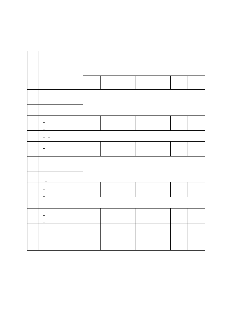
Table 3.6:
Fire resistance classification of masonary walls made of
dense and lightweight aggregate concrete units
complying with EN 771-3
Criterion REI - Separating loadbearing cavity wall with one leaf loaded
Minimum wall thickness (mm) for
fire resistance classification (min)
REI - cavity wall
Row
num
ber
material properties
unit strength f
b
[N/mm²]
density
ρ
[kg/m³]
30
45
60
90
120
180
240
1
Cavity Walls-Group 1
mortar :
general purpose, thin layer,
lightweight
1.1
lightweight aggregate
2< f
b
< 8
400 <
ρ
< 1.400
1.1.1
1.1.2
100 %
f < 2,4 N/mm²
2 x 240
(2 x 175)
1.1.3
1.1.4
60 %
f < 1,3 N/mm²
1.2
dense aggregate
6 < f
b
< 20
1.400<
ρ
< 2.000
1.2.1
1.2.2
100 %
f < 4,4 N/mm²
2 x 175
(2 x 175)
1.2.3
1.2.4
60 %
f < 2,5 N/mm²
2
Cavity Walls-Group 2
mortar :
general purpose, thin layer,
lightweight
2.1
lightweight aggregate
2 < f
b
< 8
400<
ρ
< 1.400
2.1.1
2.1.2
100 %
f < 2 N/mm²
2 x 240
(2 x 175)
2.1.3
2.1.4
60 %
f < 1 N/mm²
2.2
dense aggregate
6 < f
b
< 20
1.400<
ρ
< 2.000
2.2.1
2.2.2
100 %
f < 4 N/mm²
2 x 175
(2 x 175)
2.2.3
2.2.4
60 %
f < 2 N/mm²
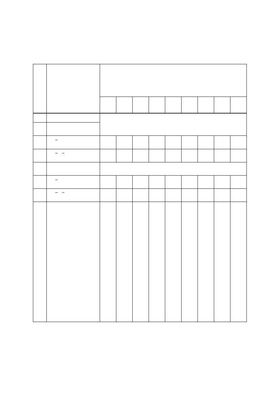
Table 4.1:
Fire resistance classification for masonary wall made of
autoclaved aerated concrete units
complying with EN 771-4
Criterion EI - separating non-loadbearing
Minimum wall thickness (mm) for
fire resistance classification (min)
EI - separating non-loadbearing
row
num
ber
material properties
unit strength f
b
[N/mm²]
gross density
ρ
[kg/m³]
15
20
30
45
60
90
120 180
240
1
Group 1
1.1
mortar :
general purpose
1.1.1
1.1.2
300 <
ρ
< 500
65
(50)
65
(50)
65
(50)
65
(65)
65
(65)
70
(70)
70
(70)
100
(100)
100
(100)
1.1.3
1.1.4
500 <
ρ
< 1.000
50
(50)
50
(50)
50
(50)
60
(60)
65
(65)
65
(65)
70
(70)
100
(100)
100
(100)
1.2
mortar :
thin layer
1.2.1
1.2.2
300 <
ρ
< 500
65
(50)
65
(50)
65
(50)
65
(65)
65
(65)
70
(70)
70
(70)
100
(100)
100
(100)
1.2.3
1.2.4
500 <
ρ
< 1.000
50
(50)
50
(50)
50
(50)
60
(50)
60
(50)
60
(50)
65
(65)
100
(90)
100
(100)
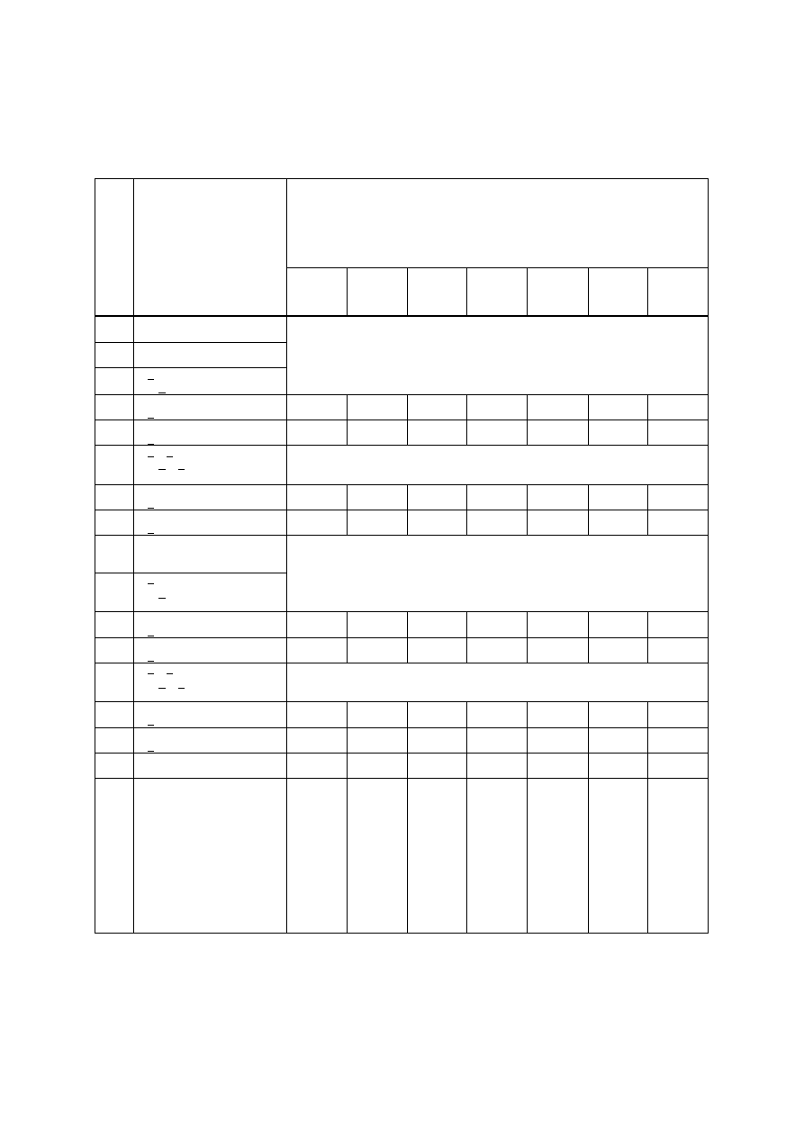
Table 4.2:
Fire resistance classification for masonary wall made of
autoclaved aerated concrete units
complying with EN 771-4
Criterion REI - Separating loadbearing single-leaf walls
Minimum wall thickness (mm) for
fire resistance classification (min)
REI - separating loadbearing
row
num
ber
material properties
unit strength f
b
[N/mm²]
gross density
ρ
[kg/m³]
30
45
60
90
120
180
240
1
Group 1
1.1
mortar :
general purpose
2 < f
b
< 4
350 <
ρ
< 500
*)
100 %
f < 0,6 N/mm²
100
(100)
100
(100)
100
(100)
125
(125)
150
(150)
175
(175)
225
(225)
60 %
f < 0,36 N/mm²
100
(100)
100
(100)
100
(100)
100
(100)
125
(125)
150
(150)
200
(200)
4 < f
b
< 8
500 <
ρ
< 1.000
**)
100 %
f < 2,0 N/mm²
100
(100)
100
(100)
100
(100)
100
(100)
100
(100)
125
(125)
150
(150)
60 %
f < 1,2 N/mm²
100
(100)
100
(100)
100
(100)
100
(100)
100
(100)
125
(125)
150
(150)
1.2
mortar :
thin layer
1.2.1
1.2.2
2 < f
b
< 4
350 <
ρ
< 500
100 %
f < N/mm²
60 %
f < N/mm²
1.2.3
1.2.4
4 < f
b
< 8
500 <
ρ
< 1.000
100 %
f < N/mm²
60 %
f < N/mm²
(*) for row 2.1: Assumption: The new European test method is based on centric loading
**) for row 2.2: Excentric loading is taken into account, because we have no other testing experience
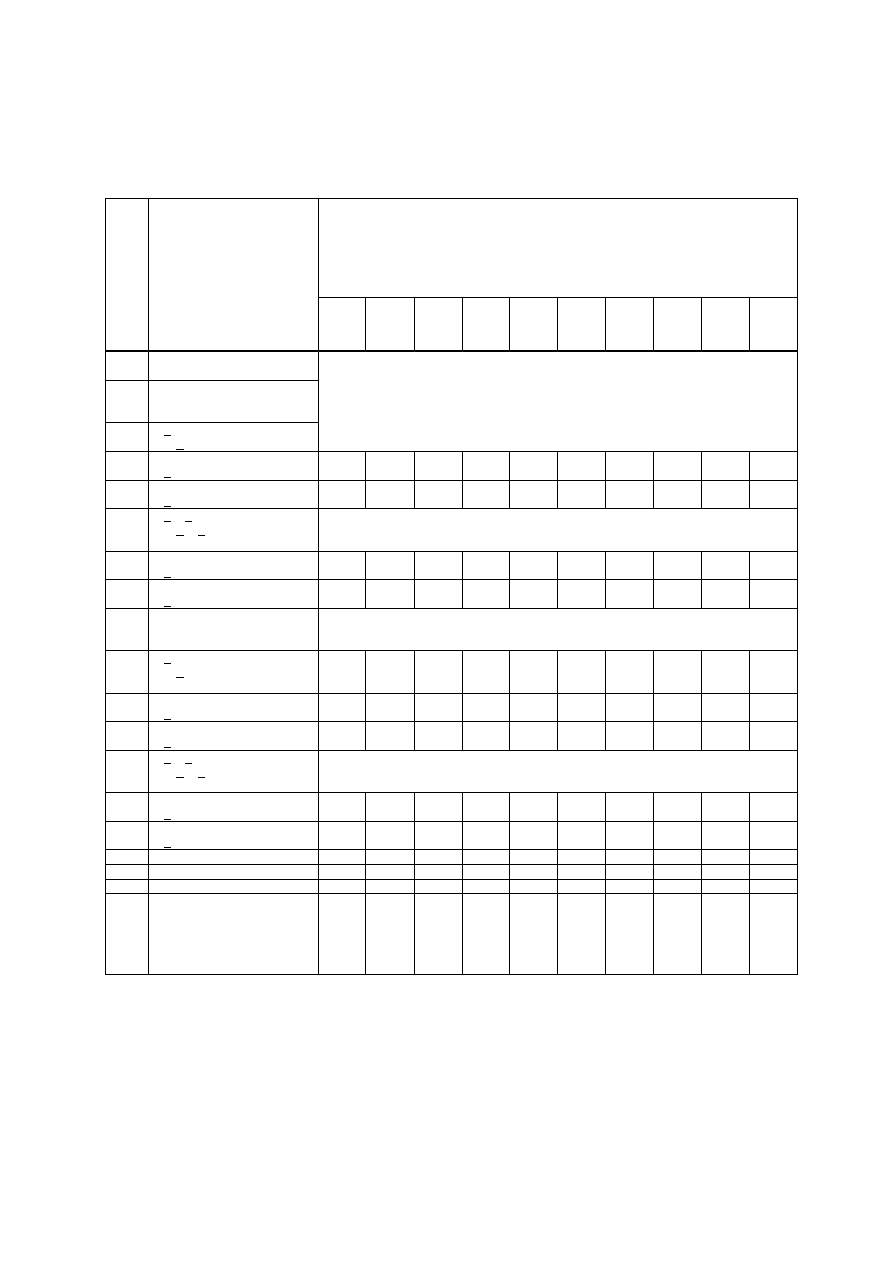
Table 4.3:
Fire resistance classification of masonary walls made of
autoclaved aerated concrete units
complying with EN 771-4
Criterion R - Non-separating loadbearing single-leaf walls - length > 1,0 m
Minimum wall thickness (mm) for
fire resistance classification (min)
R - nonseparating loadbearing
row
num
ber
material properties
unit strength f
b
[N/mm²]
gross density
ρ
[kg/m³]
15
20
30
45
60
90
120 180 240 360
1
Group 1
1.1
mortar :
general purpose,
2 < f
b
< 4
350 <
ρ
< 500
*)
100 %
f < 0,6 N/mm² ???
150
(125)
150
(125)
175
(150)
175
(150)
175
(150)
240
(175)
300
(240)
300
(240)
300
(300)
60 %
f < 0,36 N/mm² ???
100
(100)
125
(100)
125
(100)
150
(125)
150
(125)
175
(150)
175
(150)
240
(175)
300
(200)
4 < f
b
< 8
500 <
ρ
< 800 ???
**)
100 %
f < 2,0 N/mm² ???
125
(100)
125
(100)
125
(100)
125
(100)
150
(125)
175
(150)
240
(175)
240
(175)
240
(240)
60 %
f < 1,2 N/mm² ???
100
(100)
100
(100)
100
(100)
100
(100)
125
(100)
150
(125)
150
(125)
175
(120)
240
(175)
1.2
mortar :
thin layer
r
1.2.1
1.2.2
2 < f
b
< 4
350 <
ρ
< 500
100 %
f < N/mm²
60 %
f < N/mm²
1.2.3
1.2.4
4 < f
b
< 8
500 <
ρ
< 800 ???
100 %
f < N/mm²
60 %
f < N/mm²
Table 4.4:
Fire resistance classificationof masonary walls made of
autoclaved aerated concrete units
complying with EN 771-4
Criterion R - Non-separating leadbearing single-leaf columns - length <
1,0 m
Minimum wall thickness (mm) for
fire resistance classification (min)
R - nonseparating loadbearing column
row
nu
mb
er
material
properties
unit strength f
b
[N/mm²]
gross density
ρ
[kg/m³]
mini
mum
wall
lengt
h
(mm)
15
20
30
45
60
90 120 180 240 360
1
Group 1
1.1
mortar :
general purpose,
2 < f
b
< 4
350 <
ρ
< 500
*)
100 %
f < 0,6 N/mm² ???
100
125
150
175
200
240
300
365
?
( )
?
( )
?
( )
300
( )
240
( )
200
( )
175
( )
150
( )
?
?
?
365
300
240
200
175
?
?
?
490
365
300
240
200
?
?
?
490
490
365
300
240
?
?
?
490
490
365
300
240
?
?
?
*)
*)
615
490
365
?
?
?
*)
*)
730
490
490
?
?
?
*)
*)
730
615
615
730
615
490
60 %
f < 0,36 N/mm² ???
100
125
150
175
200
240
300
365
?
?
?
240
175
175
150
150
?
?
?
300
200
200
175
175
?
?
?
365
240
240
240
175
?
?
?
365
365
240
240
175
?
?
?
365
365
240
240
175
?
?
?
490
365
300
240
240
?
?
?
490
490
365
300
240
?
?
?
490
490
365
300
240
?
?
?
*)
*)
730
615
615
4 < f
b
< 8
500 <
ρ
< 1.000
**)
100 %
f < 2,0 N/mm² ???
100
125
150
175
200
240
300
365
?
?
?
240
200
175
150
150
?
( )
?
( )
?
( )
300
( )
240
( )
200
( )
175
( )
150
( )
?
?
?
365
300
240
200
175
?
?
?
365
365
300
240
200
?
?
?
365
365
300
240
200
?
?
?
730
615
490
365
300
?
?
?
*)
730
615
365
365
?
?
?
*)
730
615
490
490
?
?
?
615
615
615
490
365
Minimum wall thickness (mm) for
fire resistance classification (min)
R - nonseparating loadbearing column
row
nu
mb
er
material
properties
unit strength f
b
[N/mm²]
gross density
ρ
[kg/m³]
mini
mum
wall
lengt
h
(mm)
15
20
30
45
60
90 120 180 240 360
60 %
f < 1,2 N/mm² ???
100
125
150
175
200
240
300
365
?
?
?
175
150
150
150
150
?
?
?
240
175
175
150
150
?
?
?
300
200
200
200
150
?
?
?
300
300
200
200
150
?
?
?
300
300
200
200
150
?
?
?
365
300
240
200
200
?
?
?
365
365
300
240
200
?
?
?
490
490
490
365
300
1.2
mortar :
thin layer
r
1.2.1
1.2.2
2 < f
b
< 4
350 <
ρ
< 500
100 %
f < N/mm²
100
125
150
175
200
240
300
365
60 %
f < N/mm²
100
125
150
175
200
240
300
365

Minimum wall thickness (mm) for
fire resistance classification (min)
R - nonseparating loadbearing column
row
nu
mb
er
material
properties
unit strength f
b
[N/mm²]
gross density
ρ
[kg/m³]
mini
mum
wall
lengt
h
(mm)
15
20
30
45
60
90 120 180 240 360
1.2.3
1.2.4
4 < f
b
< 8
500 <
ρ
< 1.000
100 %
f < 2 N/mm²
100
125
150
175
200
240
300
365
60 %
f < 1 N/mm²
100
125
150
175
200
240
300
365
**) Do the changes in row 3 have an influence on the values in row 4? Are there possibilities for minimum wall length: 100, 125
and 150 mm?
Table 4.5:
Fire resistance classification of masonary walls made of
autoclaved aerated concrete units
complying with EN 771-4
Criterion REI-M or EI-M - Separating loadbearing single-leaf walls
Minimum wall thickness (mm) for
fire resistance classification (min)
REI-M or EI-M
row
num
ber
material properties
unit strength f
b
[N/mm²]
gross density
ρ
[kg/m³]
30
60
90
120
180
240
1
Group 1 - REI - M
1.1
mortar :
general purpose
2 < f
b
< 4
350 <
ρ
< 500
*)
100 %
f < 0,6 N/mm² ???
60 %
f < 0,36 N/mm² ???
4 < f
b
< 8
500 <
ρ
< 1.000
**)
100 %
f < 2,0 N/mm² ???
300
( )
300
( )
300
( )
365
( )
365
( )
60 %
f < 1,2 N/mm² ???
1.2
mortar :
thin layerr
1.2.1
1.2.2
2 < f
b
< 4
350 <
ρ
< 500
100 %
f < N/mm²
300
( )
300
( )
300
( )
365
( )
365
( )
60 %
f < N/mm²
1.2.3
1.2.4
4 < f
b
< 8
500 <
ρ
< 1.000
100 %
f < N/mm²
240
( )
240
( )
240
( )
300
( )
300
( )
60 %
f < N/mm²
2
Group 1 - EI - M
2.1
mortar :
general purpose
2 < f
b
< 4
350 <
ρ
< 500
*)
100 %
f < 0,6 N/mm² ???
60 %
f < 0,36 N/mm² ???
4 < f
b
< 8
500 <
ρ
< 1.000
**)
100 %
f < 2,0 N/mm² ???
300
( )
300
( )
300
( )
365
( )
365
( )
60 %
f < 1,2 N/mm² ???
2.2
mortar :
thin layerr
1.2.1
1.2.2
2 < f
b
< 4
350 <
ρ
< 500
100 %
f < N/mm²
300
( )
300
( )
300
( )
365
( )
365
( )
60 %
f < N/mm²
1.2.3
1.2.4
4 < f
b
< 8
500 <
ρ
< 800 ???
100 %
f < N/mm²
240
( )
240
( )
240
( )
300
( )
300
( )
60 %
f < N/mm²
Table 4.6:
Fire resistance classification of masonary walls made of
autoclaved aerated concrete units
complying with EN 771-4
Criterion REI - Separating loadbearing cavity wall with one leaf loaded
Minimum wall thickness (mm)
for fire resistance classification (min)
REI - cavity wall
row
num
ber
material properties
unit strength f
b
[N/mm²]
density
ρ
[kg/m³]
30
45
60
90
120
180
240
1
Group 1
1.1
mortar :
general purpose
2 < f
b
< 4
350 <
ρ
< 500
*)
100 %
f < 0,6 N/mm² ???
2 x 90
(2 x 90)
2 x 90
(2 x 90)
2 x 100
(2 x 100)
2 x 100
(2 x 100)
60 %
f < 0,36 N/mm² ???
4 < f
b
< 8
500 <
ρ
< 1.000
**)
100 %
f < 2,0 N/mm² ???
2 x 90
(2 x 90)
2 x 90
(2 x 90)
2 x 100
(2 x 100)
2 x 100
(2 x 100)
60 %
f < 1,2 N/mm² ???
1.2
mortar :
thin layer
1.2.1
1.2.2
2 < f
b
< 4
350 <
ρ
< 500
100 %
f < N/mm²
60 %
f < N/mm²
1.2.3
1.2.4
4 < f
b
< 8
500 <
ρ
< 1.000
100 %
f < N/mm²
60 %
f < N/mm²
Wyszukiwarka
Podobne podstrony:
Eurocode 8 Part 1 prEN 1998 1 (12 2003)
Eurocode 1 Part 1,6 prEN 1991 1 6 2004
Eurocode 1 Part 2 prEN 1991 2 2002
Eurocode 1 Part 1,2 prEN 1991 1 2 2002
Eurocode 1 Part 1,1 prEN 1991 1 1 2001
Eurocode 6 Part 3 DDENV 1996 3 1999
Eurocode 4 Part 1,1 prEN 1994 1 1 2004
Eurocode 1 Part 1,3 prEN 1991 1 3 2003
Eurocode 2 Part 1,2 prEN 1992 1 2 2004
Eurocode 1 Part 3 prEN 1991 3 2002
Eurocode 8 Part 5 prEn 1998 5 (12 2003)
Eurocode 2 Part 3 prEN 1992 3 2004
Eurocode 3 Part 2 (prEN 1993 2 March 2004)
Eurocode 8 Part 4 prEN 1998 4 2003 (12 2003)
Eurocode 1 Part 1,5 prEN 1991 1 5 2003
Eurocode 1 Part 1,4 prEN 1991 1 4 2004
Eurocode 6 Part 1,3 DDENV 1996 1 3 2001
Eurocode 3 Part 1,5 prEN 1993 1 5 2004 (Juin 2004)
Eurocode 8 Part 3 prEN 1998 3 (07 2003)
więcej podobnych podstron