S E R V I C E
Whirlpool Europe
Customer Services
ADG 9540/1 AV
This documentation is only intended for qualified technicians who are aware of the respec-
tive safety regulations.
Date: 15.04.1997
Subject to modification
Document-No.: 4812 718 12471
Model
ADG 9540/1 AV
Version
8542 954 10130
Page
Technical data
2 - 4
Spare part list
5 - 6
Exploded view
7 - 8
Circuit diagram
9
Program diagram
10
Text/Legend
11 - 19
Family
A 5
Service Manual
Dishwasher
integratable
ADG 9540/1 AV

S E R V I C E
15.04.1997 / Page 2
Whirlpool Europe
Doc. No: 4812 718 12471
Customer Service
Technical data
Dimension
Height
82,0-87,0 cm
Width
59,5
cm
Depth
57,0
cm
Weight
55,0
kg
Wooden door
Thickness min..
16
mm
Thickness max.
25
mm
Width min.
592
mm
Width max.
595
mm
Height min.
571,5
mm
Height max.
604
mm
Weight max.
5,5
kg
Max. stick out over lower
edge of appliance door
90
mm
Specification (normal program)
Capacity
12
standard
setting pl.
Water consumption
22
l
Energy consumption
1,5
kWh
Program time
~ 82
min
Noise level
52
db (A)
Detergent consumption
25
ml
Salt consumption
by 21˚ dh
<20
g
Hot water connect. up to
60
˚C
Alarms
Refill salt
Water leakage
Program information
Pre rinse / pre wash
Main wash
Drying
End
Start indicator
Volume (normal program)
Water
Volume
Level
Regeneration
0,3 l
15 mm
Back rinse 3x
1,0 l
68 mm
Prewash
5,0 l
125 mm
Main wash
6,0 l
129 mm
Intermediate rinse 1
5,0 l
125 mm
Intermediate rinse 2
5,0 l
125 mm
Clear rinse
5,0 l
125 mm
Safety / overflow
8,5 l
141 mm
Measuring the level
Remove the coarse sieve, put in a measuring
meter into the sump, measure the hight of the
water level.
Detergent max.
Pre-wash
10
cm
3
Main-wash
45
cm
3
Rinse aid
125
cm
3
6 Dosage steps
1 - 6
cm
3
Water softener
Saltcontainer
2
kg
Resin container
900
cm
3
Regeneration dosage
300
cm
3
Water pressure
Inlet pressure
0,3-10
bar
Spray pump pressure
0,4
bar
Rotations
Spray pump motor
2800
RPM
Drain pump motor
2800
RPM
Spray arm lower
~ 30
RPM
Spray arm upper
~ 35
RPM
Ceiling rotor
~ 60
RPM
Flow rates / Inlet volume
Flow meter (at 0,3 bar
= quantity 1,1 l/min)
208
lmp/l
Spray pump
~ 70
l/min
Drain pump
16
l/min
Pump height max.
1,3
m
Inlet valve
4,5
l/min
Valve for sieve
8
l/min
Spray arm lower
33
l/min
Sprayarm upper
30
l/min
Ceiling rotor
8
l/min
Water distribution
Fine sieve
100
%
Self cleaning
micro filter
~ 32
%

S E R V I C E
Whirlpool Europe
15.04.1997 / Page 3
Customer Service
Doc. No: 4812 718 12471
Technical data
Electrical data
Base data
Voltage
230
V
Frequency
50
Hz
Total power
2,0-2,2
kW
Fuse
10
A
Motor
Spray pump motor
Voltage
220/230
V
Power consumption
~190
W
HI
69
Ω
HA
36,2
Ω
Capacitor
4
µ
F
Drain pump motor
Voltage
220/240
V
Resistance
146
Ω
Heating
1 Element system
Voltage
220
V
Power consumption
1800
W
Resistance
12,1-13,4
Ω
Heating speed
~ 2,5
˚C/min
Temperature on surface
~ 115
˚C
Double safety thermostat
self reset
85
˚C
Potentiometer
Position 0
2,0
k
Ω
Position 1
4,3
k
Ω
Position 2
9,0
k
Ω
Position 3
13,3
k
Ω
Position 4
17,5
k
Ω
Position 5
22,2
k
Ω
Position 6
24,2
k
Ω
Water valves
Single valve at inlet hose
Voltage
220/240
V
Frequency
50/60
Hz
Resistance
3,67
k
Ω
Regenerating valve
Voltage
220/240
V
Frequency
50/60
Hz
Resistance
3,13
k
Ω
Valve for sieve
Voltage
220/240
V
Frequency
50/60
Hz
Resistance
3,83
k
Ω
Coil of dispenser
Voltage
220/240
V
Frequency
50/60
Hz
Resistance
1,43
k
Ω
Relay
Heating relays
Voltage
220/240
V
Frequency
50/60
Hz
Resistance
5,5
k
Ω
Reedcontact
flow meter
salt control

S E R V I C E
15.04.1997 / Page 4
Whirlpool Europe
Doc. No: 4812 718 12471
Customer Service
Technical data
NTC
15 ˚C
75
k
Ω
20 ˚C
62
k
Ω
30 ˚C
43
k
Ω
40 ˚C
28
k
Ω
50 ˚C
19
k
Ω
60 ˚C
13
k
Ω
70 ˚C
9
k
Ω
80 ˚C
6
k
Ω
85 ˚C
5
k
Ω
Regeneration
Volume
300
cm
3
Position 0
after wash cycles
--
water hardness
0-5
˚dh
0-0,9
mmol/l
0-9
˚Fh
Position 1
after wash cycles
6-8
water hardness
6-10
˚dh
1-1,8
mmol/l
10-18
˚Fh
Position 2
after wash cycles
5-6
water hardness
11-15
˚dh
1,9-2,7
mmol/l
19-27
˚Fh
Position 3
after wash cycles
4
water hardness
16-21
˚dh
2,8-3,7
mmol/l
28.37
˚Fh
Position 4
after wash cycles
3
water hardness
22-28
˚dh
3,8-5,0
mmol/l
38-50
˚Fh
Position 5
after wash cycles
2
water hardness
29-35
˚dh
5,1-6,3
mmol/l
51-63
˚Fh
Position 6
after wash cycles
1
water hardness
36-60
˚dh
6,4-10,7
mmol/l
64-107
˚Fh
Salt consumption
for regeneration
77
g
Number of cycles
with 2 kg salt
26

S E R V I C E
Whirlpool Europe
15.04.1997 / Page 5
Customer Service
Doc. No: 4812 718 12471
Spare part list
Model
ADG 9540/1 AV
Service No.
854295410130
Version
854295410130
Pos. No. 12NC Code
Description
003 0
4812 440 19382
Traverse
004 0
4812 440 18952
Drip tray assy
004 1
4812 401 18402
Holder
011 0
4812 505 18369
Foot long
011 1
4812 528 98002
Shaft flexible
011 2
4812 528 78032
Slide disc f.foot
011 3
4812 535 98048
Gear
011 4
4812 528 98001
Roll f.foot
022 0
4812 440 19398
Side panel left
022 1
4812 440 19397
Side panel right
022 2
4812 440 18953
Spacer
024 0
4812 440 18948
Panel, rear to 97/07
024 0
4812 440 19401
Panel, rear from 97/07
040 1
4812 417 18774
Hinge left
040 2
4812 417 18773
Hinge right
044 0
4812 492 38362
Spring f.door
044 1
4812 492 38364
Spring f.cap
047 0
4812 404 48591
Brake f.door
047 1
4812 401 18397
Band,brake
047 2
4812 404 68023
Hook
053 0
4812 440 88875
Plinth
103 0
4812 440 18986
Door outer
105 0
4812 404 48611
Fastener door
105 2
4812 505 68004
Clip
120 0
4812 440 18961
Door,inner
120 1
4812 440 18955
Batten
130 0
4812 417 58361
Tilt lock
131 0
4812 401 18416
Hook lock
175 3
4812 466 68532
Batten
191 0
4812 466 68534
Gasket door
192 0
4812 466 68467
Gasket, door lower
200 0
4812 418 18183
Container cpl.
241 0
4812 458 18276
Basket upper straight
241 1
4812 458 18324
Holder cups rigth white
241 2
4812 535 78036
Bearing
241 3
4819 528 88065
Wheel,basket upper
241 6
4812 458 18333
Holder glasses
241 8
4812 466 68482
Spacer cap set
242 0
4812 458 18274
Basket lower cpl.
242 1
4812 528 88069
Wheel,basket lower
242 2
4812 458 18262
Plate,support f.basket lower
242 3
4812 458 18275
Plate,support f.basket lower
243 0
4812 458 18272
Basket cutlery
261 0
4819 462 38271
Rail telescope, inner
261 1
4819 404 48819
Cap rail
261 2
4812 462 78995
Cap rail ahead
263 0
4819 520 18013
Ball cage cpl.
263 1
4812 520 48001
Ball Niro 8 D
265 0
4812 404 48599
Basket adjustm. cpl.
265 2
4812 404 48589
Grip basket adjustment
301 0
4812 453 79541
Control panel AV
303 1
4812 417 58368
Child-prooflock AV
305 0
4812 440 19434
Batten AV
305 1
4819 502 18241
Screw synthetic
305 2
4819 505 18191
Nut
Pos. No. 12NC Code
Description
305 3
4812 440 19356
Batten adjustable 5mm AV
305 4
4812 440 19357
Batten adjustable 10mm AV
322 0
4812 453 79891
Insert panel AV
331 0
4812 413 58896
Knob program cpl. AV
331 1
4812 325 88002
Ring knob AV
332 0
4812 410 28537
Push button cap AV
350 0
4812 276 58057
Display board (DB)
351 1
4812 381 28021
Guide,light
400 0
4812 361 58119
Motor + spraypump cpl.220/240V
405 0
4812 360 18358
Spray pump
405 1
4819 515 28158
Gasket
420 0
4812 121 18132
Capacitor
421 0
4812 121 18156
Interf.filter from 97/07
430 0
4812 360 18357
Pump,draining
430 1
4812 466 68506
Ring,sealing
450 0
4812 259 28657
Heating element
480 0
4812 321 28364
Cable harness set
480 1
4812 321 28371
Cable
480 3
4812 401 18418
Protector f.wiring
480 4
4812 401 18419
Cover of cable
490 0
4812 321 18026
Cable,mains 3m to 97/07
490 0
4819 321 18136
Cable,mains 2m from 97/07
490 1
4812 321 28367
Strain relief from 97/07
521 0
4812 214 78172
Control board (CB)
531 0
4812 273 18054
Switch waterhardness
531 1
4812 273 18053
Wheel,fingertip
571 2
4812 281 28362
Sieve valve
575 0
4812 281 28361
Regen.valve
583 0
4812 271 28355
Switch diaphragm
612 0
4812 280 58025
Relay heating
616 0
4812 281 18047
Contact,reed salt
620 0
4812 218 38038
User board (UB)
623 0
4812 271 38356
Microswitch
633 0
4812 271 38355
Microswitch
680 0
4812 418 68133
Combidosage
680 1
4812 466 68495
Gasket
681 1
4812 466 68497
Gasket
681 2
4812 440 18975
Flap
682 0
4812 466 68496
Gasket
691 0
4812 282 68012
Feeler NTC
700 0
4812 530 28788
Hose, inlet aqua stop 2m
700 0
4812 530 28804
Hose, inlet aqua stop 4,2m
700 1
4812 480 48019
Sieve
700 2
4812 520 58002
Gasket set
701 1
4812 310 18153
Yoke clamp set
701 2
4819 401 18423
Holder
710 0
4812 418 68128
Monoblock
710 2
4819 310 38536
Nut threaded ring set
710 3
4819 466 69562
Gasket set
714 0
4812 462 78993
Threaded cap
714 2
4812 440 18963
Cabinet non-return flap
716 0
4812 418 68147
Reg.dosage
716 1
4812 466 68475
Gasket
716 2
4812 462 78994
Cover
721 0
4812 360 68043
Hub lower cpl.

S E R V I C E
15.04.1997 / Page 6
Whirlpool Europe
Doc. No: 4812 718 12471
Customer Service
Spare part list
Model
ADG 9540/1 AV
Service No.
854295410130
Version
854295410130
Pos. No. 12NC Code
Description
721 1
4812 360 68047
Arm,spray lower cpl.
721 2
4812 466 68491
Gasket 25x2,3B
721 3
4812 466 68489
Gasket 76x2,5
721 4
4812 418 18176
Cabinet
722 0
4812 360 68044
Arm,spray upper
722 2
4812 360 68056
Hub upper straight cpl.
723 0
4812 360 68049
Arm,spray
723 1
4812 466 68483
Gasket
723 2
4812 404 48597
Clip,fix sprayarm
723 3
4812 505 18362
Connect,gaspipe
726 0
4812 530 28786
Tube
726 1
4812 530 28787
Tube
726 2
4812 505 18358
Nut
726 3
4812 466 68512
Gasket
726 4
4812 462 79633
Centering
743 0
4812 511 48171
Capacitor
743 1
4812 530 28102
Hose, inlet
743 3
4812 505 18364
Nut
743 4
4812 530 28807
Hose 9x1,5x270+10
743 7
4812 466 68514
Gasket
751 0
4812 418 18169
Water collector
751 1
4812 418 18171
Water guide
751 2
4812 440 18954
Fastener frame
755 0
4812 530 28785
Bend
755 2
4812 530 48148
Tray,leak
756 0
4812 360 58099
Floater
761 0
4812 480 58061
Sieve fine
761 1
4812 480 58072
Sieve insert
762 0
4812 480 58065
Microfilter
763 0
4812 480 58057
Sieve coarse
781 0
4812 530 28737
Hose,draining
781 1
4819 530 28286
Sleeve hose
781 2
4819 492 68405
Clip f.non-return valve
781 3
4812 281 28364
Flap non-return
783 0
4812 530 28792
Hose 11,5x3x200
783 5
4812 530 28797
Distributor
783 6
4812 530 28796
Hose 10x3x180+10
791 0
4812 532 68067
Gasket
791 2
4812 530 58093
Gasket
791 4
4812 466 68503
Gasket
791 5
4812 466 68504
Gasket
791 6
4812 466 68505
Gasket
794 1
4819 530 58032
Gasket 20x2,5
901 0
4812 401 18191
Strap 017,8
901 1
4812 401 18396
Strap
901 2
4812 401 18401
Strap
901 3
4812 401 18404
Strap 019,8-708Z
901 5
4812 401 18406
Strap 028,6-708Z
901 6
4812 401 18408
Strap 038,1-708Z
901 8
4812 401 18075
Strap 20-32/9 mm
902 1
4812 466 78361
Fastener f.buildt-in models
902 2
4812 404 78239
Holder
904 2
4812 462 79635
Cover WH 3,5x5
904 3
4812 462 79636
Cover WH 3,5x4
910 1
4812 502 18019
Screw
Pos. No. 12NC Code
Description
910 2
4812 502 18363
Screw 4,0x12-H
910 3
4812 502 18364
Screw 5x20-TORX
910 4
4812 502 18386
Screw 3,5x8-TORX T15
910 5
4812 502 18367
Screw 3,5x8-TORX T15
910 6
4812 502 18369
Screw A2F M4x6
910 7
4812 502 38132
Screw DIN 965
964 1
4812 466 68511
Gasket housing upper
993 1
4812 466 78018
Foil protection
993 2
4812 404 48609
Socket wreng foot
993 5
4822 532 80216
Funnel salt
S E R V I C E
Whirlpool Europe
15.04.1997 / Page 7
Customer Service
Doc. No: 4812 718 12471
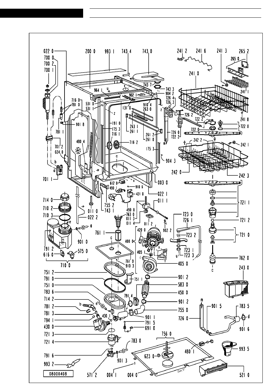
Exploded view
S E R V I C E
15.04.1997 / Page 8
Whirlpool Europe
Doc. No: 4812 718 12471
Customer Service
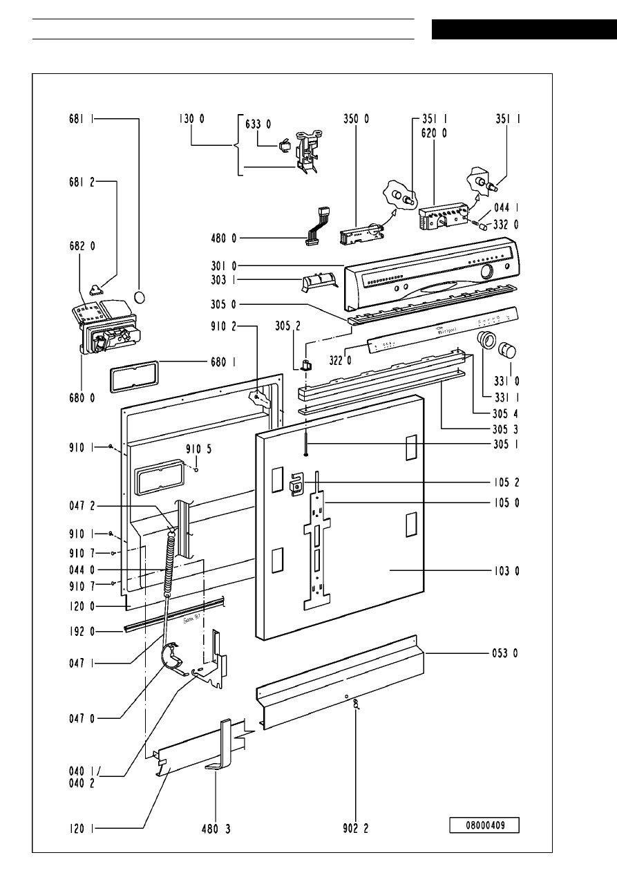
Exploded view
S E R V I C E
Whirlpool Europe
15.04.1997 / Page 9
Customer Service
Doc. No: 4812 718 12471
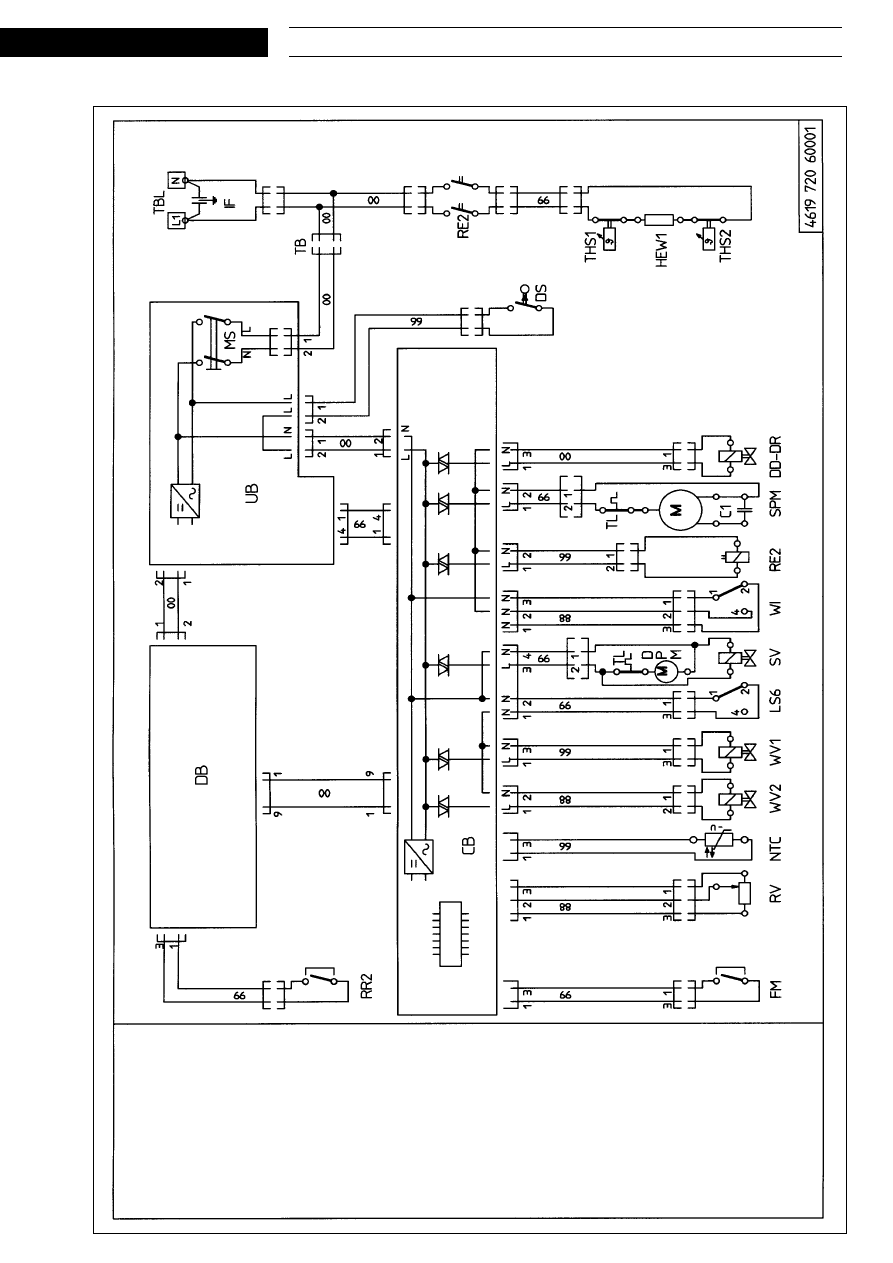
Circuit diagram
C1
Capacitor
CB
Control board
DB
Displa
y board
DPM
Drain pump motor
DD
Cleaning agent dosage
DR
Final rinse dosage
DS
Door switc
h
EM
Electro magnet
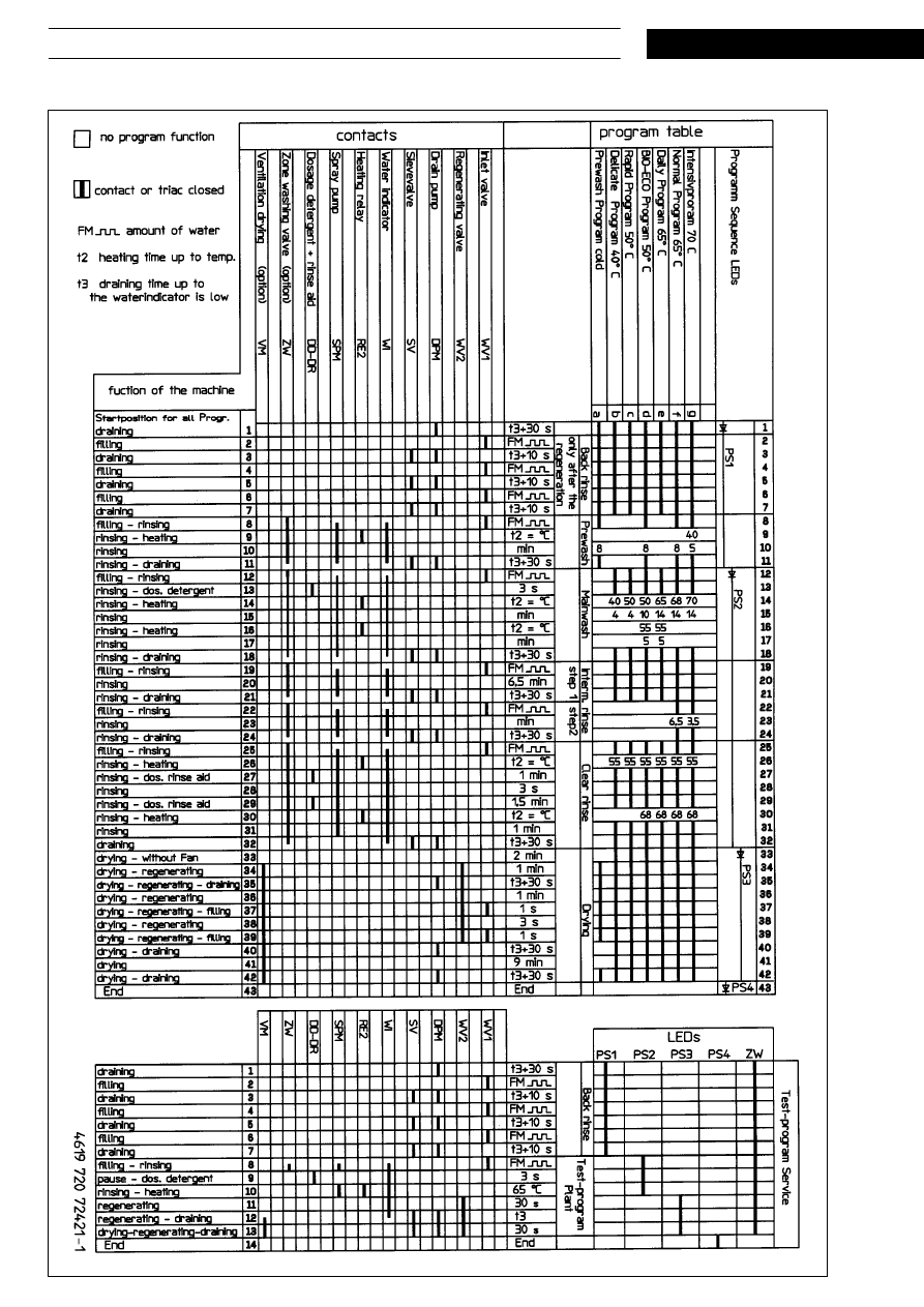
FM
Flo
w meter
HEW
Heating
IF
Interf
erence filter
L
S
6
W
ater leakage switc
h
L
Line
MS
Main switc
h
NTC
T
hermost
at
N
Neutral
R
V
W
ater hardness switc
h
RE2
Heating rela
y
RR2
R
eed rela
y salt
RR3
R
eed rela
y rinsaid
S
A
B
Spra
y
arm bloc
k
e
d
S
V
Sle
v
e
v
alv
e
SPM
Spra
y
arm motor
THS
Saf
et
y thermost
at
TB
Plug coupler
TBL
P
o
w
er supply terminal
TL
W
inding protectiv
e cont
act
UB
User board
VM
F
an v
entilator
WV1
W
ater inlet v
alv
e
WV2
W
ater regenerating v
alv
e
WI
W
ater indicator
ZW
Zone w
ashing
0
0
blac
k
66
blue
88
gre
y
99
white
S E R V I C E
15.04.1997 / Page 10
Whirlpool Europe
Doc. No: 4812 718 12471
Customer Service
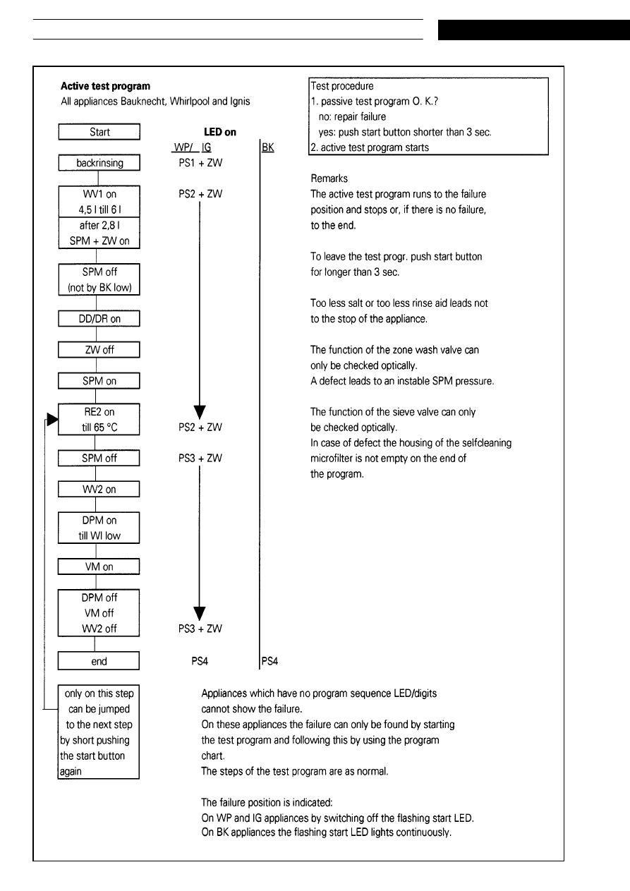
Program diagram

S E R V I C E
Whirlpool Europe
15.04.1997 / Page 11
Customer Service
Doc. No: 4812 718 12471
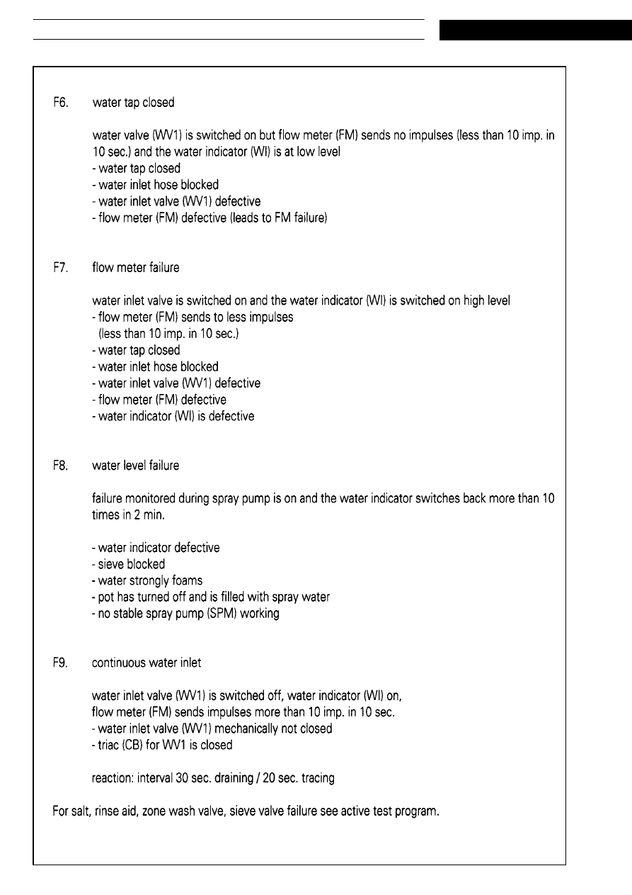
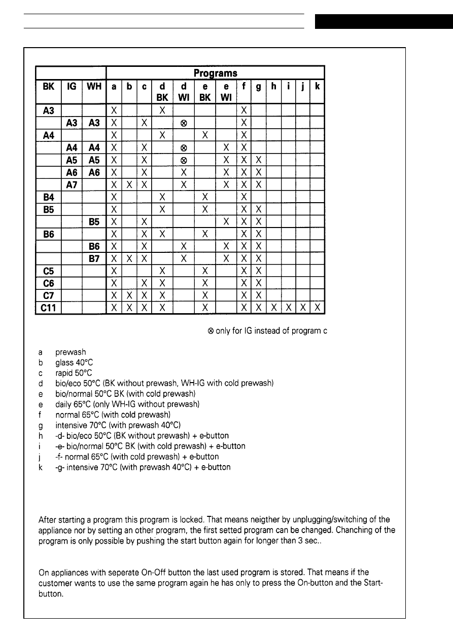
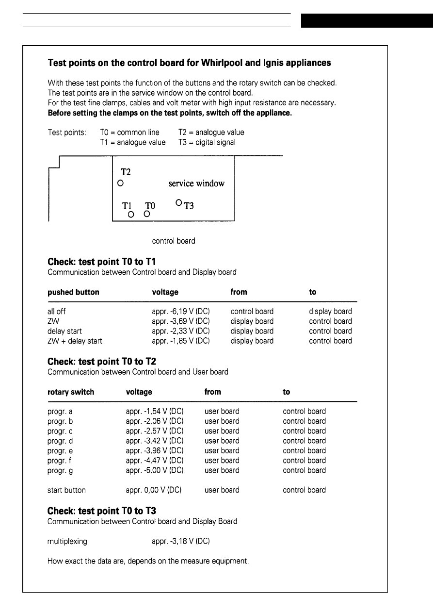
Text/Legend
S E R V I C E
15.04.1997 / Page 12
Whirlpool Europe
Doc. No: 4812 718 12471
Customer Service

S E R V I C E
Whirlpool Europe
15.04.1997 / Page 13
Customer Service
Doc. No: 4812 718 12471
Text/Legend
S E R V I C E
15.04.1997 / Page 14
Whirlpool Europe
Doc. No: 4812 718 12471
Customer Service

S E R V I C E
Whirlpool Europe
15.04.1997 / Page 15
Customer Service
Doc. No: 4812 718 12471
Text/Legend
S E R V I C E
15.04.1997 / Page 16
Whirlpool Europe
Doc. No: 4812 718 12471
Customer Service

S E R V I C E
Whirlpool Europe
15.04.1997 / Page 17
Customer Service
Doc. No: 4812 718 12471
Text/Legend
S E R V I C E
15.04.1997 / Page 18
Whirlpool Europe
Doc. No: 4812 718 12471
Customer Service

S E R V I C E
Whirlpool Europe
15.04.1997 / Page 19
Customer Service
Doc. No: 4812 718 12471
Text/Legend

S E R V I C E
15.04.1997 / Page 20
Whirlpool Europe
Doc. No: 4812 718 12471
Customer Service

S E R V I C E
Whirlpool Europe
15.04.1997 / Page 21
Customer Service
Doc. No: 4812 718 12471
Text/Legend
S E R V I C E
15.04.1997 / Page 22
Whirlpool Europe
Doc. No: 4812 718 12471
Customer Service

S E R V I C E
Whirlpool Europe
15.04.1997 / Page 23
Customer Service
Doc. No: 4812 718 12471
Text/Legend
S E R V I C E
15.04.1997 / Page 24
Whirlpool Europe
Doc. No: 4812 718 12471
Customer Service

S E R V I C E
Whirlpool Europe
15.04.1997 / Page 25
Customer Service
Doc. No: 4812 718 12471
Text/Legend
S E R V I C E
15.04.1997 / Page 26
Whirlpool Europe
Doc. No: 4812 718 12471
Customer Service

S E R V I C E
Whirlpool Europe
15.04.1997 / Page 27
Customer Service
Doc. No: 4812 718 12471
Text/Legend
S E R V I C E
15.04.1997 / Page 28
Whirlpool Europe
Doc. No: 4812 718 12471
Customer Service
Wyszukiwarka
Podobne podstrony:
LG 9540
Zetor 7520, 7540, 8520, 8540, 9520, 9540, 10540 kabina kierowcy
instrukcja obsługi WHIRLPOOL ADG 9540 O
zetor 7520,7540,8520,8540,9520,9540,10540
więcej podobnych podstron