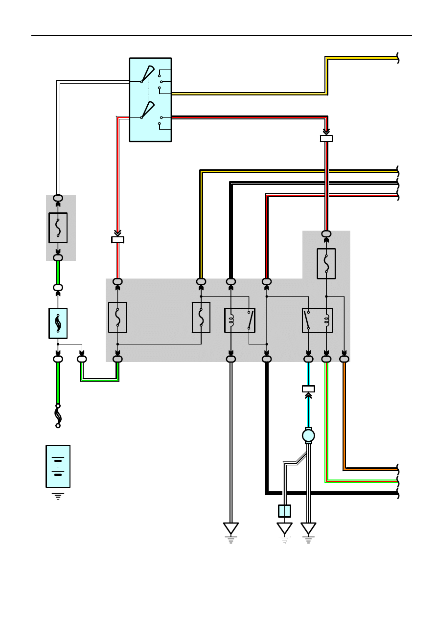
2002 CAMRY (EWD461U)
88
Engine Control (2AZ–FE)
2
3
1
5
3
2
5
1
ED
BQ
1
1
1A
2
1C
5
1D
4
1C
6
1K
6
1C
7
1C
4
1B
3
1B
9
1E
2
1
2E
2
2A
2
IF6
3
2
7
1
6
AM2
AM1
ACC
IG1
ST1
IG2
ST2
IF1
8
10A
IG2
1C
8
ID1
5
M
5
4
B–Y
B–R
B–Y
B–Y
B–W
B–R
B–O
G–R
B–W
B–G
W
W–
R
B–
G
W–
R
B–
Y
B–
W
B–
R
B–
R
B–
G
L–
B
B–
W
W–
B
L–
B
G–
R
B–
O
W–
B
F
uel
P
u
m
p
F 8
C/
O
P
N
Re
la
y
2
0
A EF
I
EF
I R
e
la
y
3
0
A AM
2
1
00A
A
L
T
FL MAIN
3. 0W
Battery
5A
A
M
1
Ignition SW
I15
2
1
BQ
W–
B
A
J
unc
ti
on
C
o
n
nec
to
r
J1
1
(T
MMK
Made
)
(T
M
C
M
ade
)
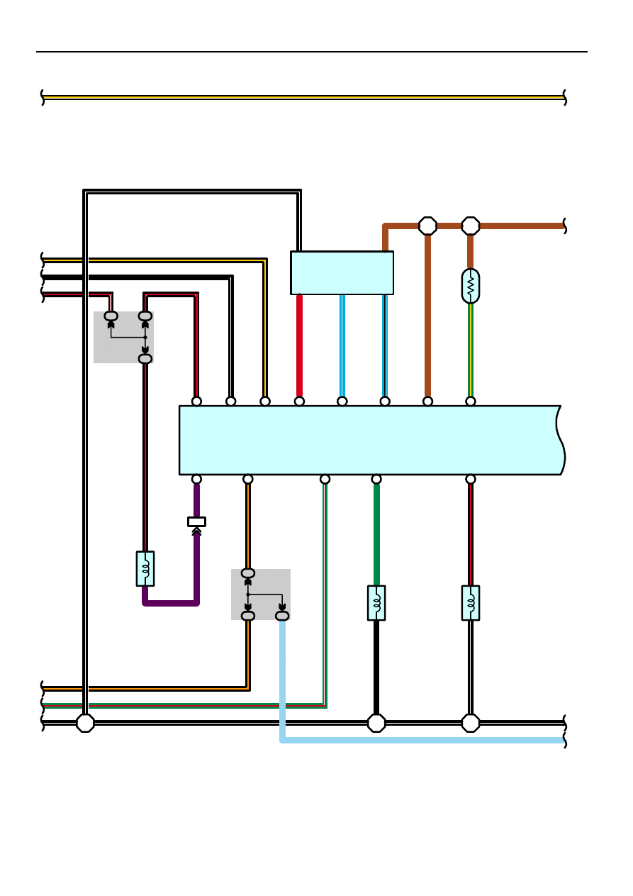
2002 CAMRY (EWD461U)
89
E14
E14
E14
2
1
1
2
ID1
6
1
2
2G
20
2G
8
A
4
A
9
A
10
C
12
C
11
A
1
A
8
A
3
D
24
D
32
E
20
E
28
E
19
2G
17
2K
17
2G
5
I 6
I 6
B–Y
B–W
B–R
BR
B–Y
B–Y
BR
BR
B–O
G–R
B–W
B–W
B–W
B–W
VV
B–
O
G–
R
G
B–
R
B–
W
B–
W
TBP
IGSW
FC
CCV
EVP1
B–
R
B–
Y
B–
W
B–
R
R
L–
W
L–
B
BR
G–
Y
B
R
VSV (Pr
e
s
s
u
re
Sw
it
c
h
in
g
Va
lv
e
)
V1
2
VSV (C
ani
s
ter
C
los
ed
V
a
lv
e
)
V 4
V 6
E 4
Mass Air Flow
Meter
M 1
+B
MREL
BATT
VG
E2G
THA
E2
THW
E2
+B
VG
E2G
THA
Engine Control Module
E 6(A), E 7(B), E 8(C), E 9(D), E10(E)
B–
W
1
5
3
2
4
B–
W
2
1
2O
5
SB
B–
O
SB
VSV
(EVAP
)
VSV
(EVAP
)
E
ngi
ne C
ool
ant
T
e
m
p
.
S
ens
or
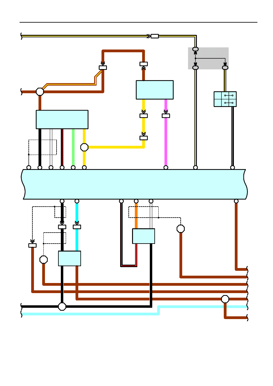
2002 CAMRY (EWD461U)
90
Engine Control (2AZ–FE)
C
17
C
5
C
4
E
31
E
21
E
18
D
9
D
8
A
21
B
22
B
4
D
4
D
23
D
31
C
1
I 6
I 7
IL1
10
IL1
6
IC2
4
ID1
2
IC2
9
IF1
5
P
N
9
6
1K
8
1K
7
1H
8
I 7
I 8
I 8
I 8
BR
BR
BR
BR
BR
BR
BR
BR
Y
B–Y
B–Y
BR
VCC
PTNK
VC
VTA
VTA2
M–
M+
OX1B
HT1B
HAF1A
AF1A+
AF1A–
E1
B–W
BR
BR
B–R
(*3
)
B
L
B–
R
(*3
)
O
W
BR
BR
BR
B–
W
BR
B–
W
(*3
)
B
W
B–
R
LG
Y
Y
YY
P
P
B–
Y
B–
W
B–
Y
BR
BR
P
a
rk
/N
e
u
tra
l
Po
s
it
io
n
SW
A 4
Heated
Oxygen
Sensor
H 5
Air Fuel
Ratio Sensor
A 8
Throttle Position
Sensor
T 3
Vapor Pressure
Sensor
V11
Engine Control Module
E 6(A), E 7(B), E 8(C), E 9(D), E10(E)
1
6
2
3
3
5
4
1
2
GE01
M+
M–
VTA2
VTA
VC
PTNK
NSW
STA
3
4
2
4
1
2
IL1
5
IL1
1
IL1
9
B
L
BR
1
3
(*3
)
E2
OX
HT
+B
E1
SB
SB
(*5)
BR–Y(* 4)
2002 CAMRY (EWD461U)
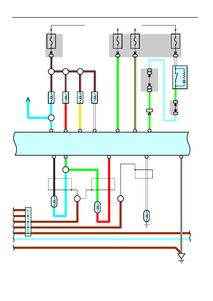
91
C
7
D
1
E
27
E
34
E
26
E
1
E
2
E
3
E
4
A
12
A
13
B
19
15A
IGN
From Power Source System (See Page 62)
1L
10
2G
1
2G
16
2G
13
E13
E13
E13
2
1
2
1
2
1
2
1
2G
7
2M
4
3A
3A
61
51
3A
3A
101
91
(* 1)
(* 2)
IJ1
7
A
A
A
A
A
A
A
A
I 7
I 8
I 8
2
1
1
2
EG
BR
BR
BR
BR
BR
BR
BR
G22+
NE–
NE+
KNK1
E03
BR
BR
B–R
B–R
SB
SB
B–
R
B–
R
B–
R
B–
R
B–
R
L
R
Y
W
G
B–
Y
G–
W
G
–
W
G–
W
W
G
W–
B
(*3
)
B–
W
L
(*3
)
G
R
(*3
)
W
W–
B
BR
BR
C
a
m
s
haf
t
Po
s
it
io
n
S
ens
or
C 1
C
ran
ks
haf
t
P
o
s
it
ion S
ens
or
C 3
K
noc
k
S
ens
or
K 2
In
je
c
to
r
N
o
. 1
I 7
In
je
c
to
r
N
o
. 2
I 8
In
je
c
to
r
N
o
. 3
I 9
In
je
c
to
r
N
o
. 4
I1
0
S
top Li
ght
SW
S1
4
Junction
Connector
J 1
10
A
T
A
IL
1
0
A
M
IR HT
R
1
5
A ST
O
P
Engine Control Module
E 6(A), E 7(B), E 8(C), E 9(D), E10(E)
# 10
#20
# 30
# 40
ELS
ELS2
STP
* 1 : Automatic A/C
* 2 : Manual A/C
* 3 : Shielded
(* 1)
(* 2)
1
2
1
SB
SB
* 4 : TMMK Made
* 5 : TMC Made
L
I 8
L
Cl
o
c
k

2002 CAMRY (EWD461U)
92
Engine Control (2AZ–FE)
10A
ETCS
From Power Source System (See Page 62)
1B
2
A
2
E
8
E
9
E
7
E
6
C
6
D
7
A
26
A
23
A
28
A
27
A
22
A
29
C
16
C
15
EH
E15
E15
E15
E
10
11 E
3
2
3
2
3
2
3
2
L–
R
L–
R
R–
W
P
LG
–B
L–Y
W–
R
W–
R
W–
R
W–
R
Ignition Coil
and Igniter No. 1
I 1
Ignition Coil
and Igniter No. 2
I 2
Ignition Coil
and Igniter No. 3
I 3
Ignition Coil
and Igniter No. 4
I 4
2
1
BR
BR
E01
E02
ME01
E04
VCP2
VPA2
EPA2
VCPA
VPA
EPA
OCV+
OCV–
W–
B
W–
B
W–
B
W–
B
R
W–
R
LG
–B
B–
R
L–
Y
LG
B–
W
Y
W–
B
W–
B
W–
B
W–
B
+BM
IGT1
IGT2
IGT3
IGT4
6
2
3
4
5
1
W–R
W–R
A18
V
V
T
S
o
lenoi
d
V 7
Engine Control Module
E 6(A), E 7(B), E 8(C), E 9(D), E10(E)
E
23
W–
R
IGF
VCP2
VPA2
EP2
VCP1
VPA1
EP1
SB
SB
Accelerator Position Sensor

2002 CAMRY (EWD461U)
93
IF3
2
IF4
17
IF4
18
IF4
16
IF3
6
IJ1
6
A
19
A
14
A
11
A
5
A
18
B
14
B
17
B
15
B
27
B
26
B
16
B
34
C
9
C
2
CODE
RXCK
TXCT
V–W
G–R
Y–G
B–O
W
P–B
R
V–
W
G–
R
G–
W
R–
L
L–
Y
V
L
G–
W
L–W
V–
W
G–
R
Y–
G
B–
O
W
P–
B
R
4
3
5
I14
1
IJ1
3
IJ1
8
IF4
4
3B
3B
108
118
3B
3B
68
78
(*1)
(*2)
3B
3B
88
98
A
15
B
33
B
31
C
10
B
12
B
13
(*2)
A
38
(*1)
A
39
P
o
w
e
r S
teer
ing O
il
Pr
e
s
s
u
re
SW
P 1
A/C Control Assembly
A13(A)
R–
W
P–
L
(*1
)
W
B
(*1
)
Y–
B
BR
BR
P–
L
(*1
)
W
B
(*1
)
Y–
B
BR
BR
IL2
16
PS
A/CS
A/CI
EOM
CODE
RXCK
TXCT
IMLD
KSW
FAN
ACMG
SPD
W
THWO
TACH
SIL
TC
WFSE
E 6(A), E 7(B), E 8(C), E 9(D), E10(E)
Engine Control Module
(*6
)
(*6
)
(*6
)
* 1 : Automatic A/C
* 2 : Manual A/C
* 6 : w/ Engine Immobiliser System
A
/C
C
ontr
o
l
A
s
s
e
m
b
ly
(*1
)
H
eat
er
C
ont
ro
l
S
W
(*2
)
U
n
lo
ck W
a
rn
in
g
S
W
F
A
N NO
. 1
Re
la
y
F
A
N NO
. 2
Re
la
y
F
A
N NO
. 3
Re
la
y
D
iode
H10(B)
Heater Control SW
(*2)
(*2
)
(*2
)
(*2
)
(*2
)
G–
W
C
30
PR2
F
A
N NO
. 1
Re
la
y
F
A
N NO
. 2
Re
la
y
F
A
N NO
. 3
Re
la
y
A/CS
A/CI
SB
W
(*1)
SB
Ignition Key Cylinder Light
Transponder Key Amplifier
2002 CAMRY (EWD461U)
94
Engine Control (2AZ–FE)
2M
1
7. 5A
OBD
From Power Source System (See Page 62)
2A
4
II
IJ
3B
3B
81
91
3B
3B
82
92
3B
3B
89
99
3B
3B
79
89
3B
3B
61
71
3B
3B
62
72
3B
3B
90
100
(* 1)
(* 2)
3A
3A
92
82
3A
3A
102
92
3A
3A
67
57
3A
3A
117
107
(* 1)
(* 2)
A
27
A
36
B
16
A
12
A
11
A
20
Combination Meter
C 7(A), C 8(B)
3B
3B
76
86
3B
3B
70
80
3B
3B
66
76
(* 1)
(* 2)
3B
3B
60
70
2L
8
2R
8
W–
B
W
BR
W–
B
S
B
BR
SG
CG
V–W
G–R
Y–G
B–O
W
P–B
R
P–
B
W
B–
O
B
–
O
W
W
G–
R
W
W
SB
W
B
15
13
7
9
16
5
4
Data Link
Connector 3
D 3
* 1 : Automatic A/C
* 2 : Manual A/C
(* 1)
(* 2)
(* 1)
(* 2)
WFSE
TC
SIL
TAC
BAT
(* 2)
(* 1)
Te
m
p
.
T
a
c
hom
et
er
S
peed
om
et
er
Malfunction
SB
(* 1)
(* 2)
(* 1)
(* 2)
A
35
W
W
19 A
IL2
5
IL2
3
IG+
1
V 1
SI
3
2
SE
P
L
(*1)
(*2)
3B
3B
115
125
3B
3B
95
105
(*1)
(*2)
IL2
14
W
R–
L
10A
GAUGE1
Vehicle Speed
Sensor
(Combination Meter)

2002 CAMRY (EWD461U)
95
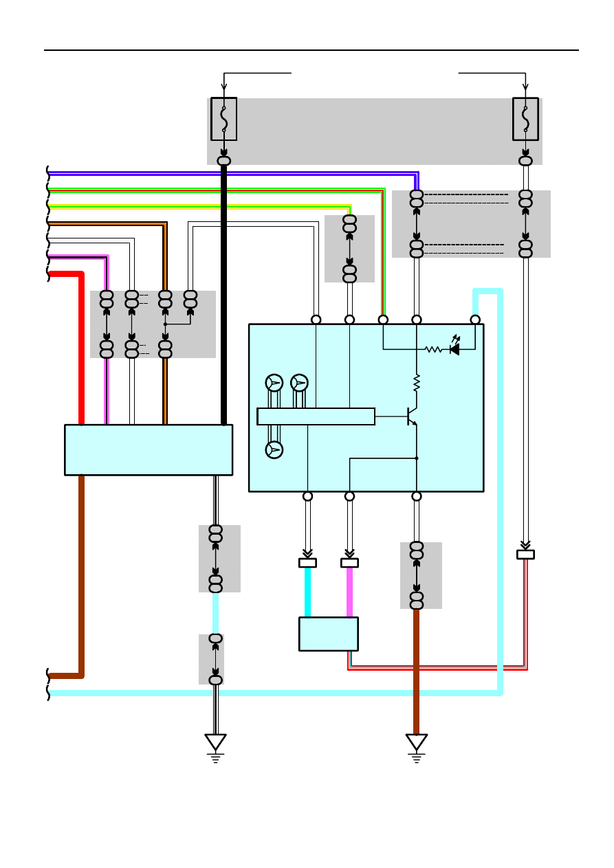
The engine control system utilizes a microcomputer and maintains overall control of the engine, transaxle etc. An outline of
the engine control is given here.
1. Input Signals
(1) Engine coolant temp. signal circuit
The engine coolant temp. sensor detects the engine coolant temp. and has a built–in thermistor with a resistance, which
varies according to the engine coolant temp.. The engine coolant temp. which is input into TERMINAL THW of the
engine control module as a control signal.
(2) Intake air temp. signal circuit
The intake air temp. sensor is installed in the mass air flow meter and detects the intake air temp. which is input as a
control signal to TERMINAL THA of the engine control module.
(3) Oxygen density signal circuit
The oxygen density in the exhaust emission is detected by the heated oxygen sensor and input as a control signal to
TERMINAL OX1B of the engine control module.
(4) RPM signal circuit
Camshaft position and crankshaft position are detected by the camshaft position sensor and crankshaft position sensor.
Camshaft position is input as a control signal to TERMINAL G22+ of the engine control module, and engine RPM is
input into TERMINAL NE+.
(5) Throttle position signal circuit
The throttle position sensor detects the throttle valve opening angle as a control signal, which is input into TERMINAL
VTA of the engine control module.
(6) Vehicle speed circuit
The vehicle speed sensor detects the vehicle speed and inputs a control signal to TERMINAL SPD of the engine control
module.
(7) Battery signal circuit
Voltage is constantly applied to TERMINAL BATT of the engine control module. With the ignition SW turned on, the
voltage for engine control module start–up power supply is applied to TERMINAL +B of the engine control module via
the EFI relay.
(8) A/C SW signal circuit
The A/C control assembly (Automatic A/C) or heater control SW (Manual A/C) inputs the A/C operations into TERMINAL
A/CS of the engine control module.
(9) Stop light SW signal circuit
The stop light SW is used to detect whether the vehicle is braking or not and the signal is input into TERMINAL STP of
the engine control module as a control signal.
(10) Starter signal circuit
To confirm whether the engine is cranking, the voltage is applied to the starter motor during cranking is detected and the
signal is input into TERMINAL STA of the engine control module as a control signal.
(11) Engine knock signal circuit
Engine knocking is detected by knock sensor and the signal is input into TERMINAL KNK1 as a control signal.
(12) Air fuel ratio signal system
The air fuel ratio is detected and input as a control signal into TERMINAL AF1A+ of the engine control module.
System Outline

2002 CAMRY (EWD461U)
96
Engine Control (2AZ–FE)
2. Control System
∗
SFI system
The SFI system monitors the engine condition through the signals input from each sensor to the engine control module.
And the control signal is output to TERMINALS #10, #20, #30, #40 of the engine control module to operate the injector
(Inject the fuel). The SFI system controls the fuel injection operation by the engine control module in response to the
driving conditions.
∗
ESA system
The ESA system monitors the engine condition through the signals input to the engine control module from each sensor.
The best ignition timing is decided according to this data and the memorized data in the engine control module and the
control signal is output to TERMINALS IGT1, IGT2, IGT3, IGT4. This signal controls the igniter to provide the best
ignition timing for the driving conditions.
∗
Heated oxygen sensor heater control system
The heated oxygen sensor heater control system turns the heater on when the intake air volume is low (Temp. of
exhaust emissions is low), and warms up the heated oxygen sensor to improve detection performance of the sensor.
The engine control module evaluates the signals from each sensor, and outputs current to TERMINAL HT1B to control
the heater.
3. Diagnosis System
With the diagnosis system, when there is a malfunction in the engine control module signal system, the malfunctioning
system is recorded in the memory. The malfunctioning system can be found by reading the code displayed by the
malfunction indicator lamp.
4. Fail–Safe System
When a malfunction has occurred in any system, if there is a possibility of engine trouble being caused by continued control
based on the signals from that system, the fail–safe system either controls the system by using data (Standard values)
recorded in the engine control module memory or else stops the engine.
2002 CAMRY (EWD461U)
97
E6 (A), E7 (B), E8 (C), E9 (D), E10 (E) Engine Control Module
BATT–E1 : Always 9.0–14.0 volts
VC–E2 : 4.5–5.5 volts (Ignition SW at ON position)
VTA–E2 : 0.3–1.0 volts (Ignition SW on and throttle valve fully closed)
3.2–4.9 volts (Ignition SW on and throttle valve fully open)
VG–E2G : 1.1–1.5 volts (Engine idling and A/C SW off)
THA–E2 : 0.5–3.4 volts (Engine idling and intake air temp. 20
°
C, 68
°
F)
THW–E2 : 0.2–1.0 volts (Engine idling and coolant temp. 80
°
C, 176
°
F)
IGF–E1 : 4.5–5.5 volts (Ignition SW at ON position)
Pulse generation (Engine idling)
SIL–E1 : Pulse generation (During transmission)
TACH–E1 : Pulse generation (Engine idling)
STA–E1 : 6.0 volts or more (Engine cranking)
FC–E01 : 9.0–14.0 volts (Ignition SW at ON position)
SPD–E1 : Pulse generation (Ignition SW on and rotate driving wheel slowly)
W–E01 : Below 3.0 volts (Ignition SW at ON position)
NSW–E1 : 9.0–14.0 volts (Ignition SW on and other shift position in P or N position)
0–3.0 volts (Ignition SW on and shift position in P or N position)
EVP1–E01 : 9.0–14.0 volts (Ignition SW at ON position)
STP–E1 : 7.5–14.0 volts (Ignition SW on and brake pedal depressed)
Below 1.5 volts (Ignition SW on and brake pedal released)
KNK1–E1 : Pulse generation (Engine idling)
PSW–E1 : 9.0–14.0 volts (Ignition SW at ON position)
HAF1A–E04 : Below 3.0 volts (Engine idling)
IGSW–E1 : 9.0–14.0 volts (Ignition SW at ON position)
MREL–E1 : 9.0–14.0 volts (Ignition SW at ON position)
G22+, NE+ –NE– : Pulse generation (Engine idling)
OCV+ –OCV– : Pulse generation (Ignition SW at ON position)
HT1B–E1 : 9.0–14.0 volts (Engine idling)
Below 3.0 volts (Ignition SW at ON position)
AF1A+ –E1 : 3.3 volts (Ignition SW at ON position)
AF1A– –E1 : 3.0 volts (Ignition SW at ON position)
OX1B–E1 : Pulse generation (Maintain engine speed at 2500 rpm for 90 sec. after warming up)
IGT1, IGT2, IGT3, IGT4–E1 : Pulse generation (Engine idling)
#10, #20, #30, #40–E01 : 9.0–14.0 volts (Ignition SW at ON position)
Pulse generation (Engine idling)
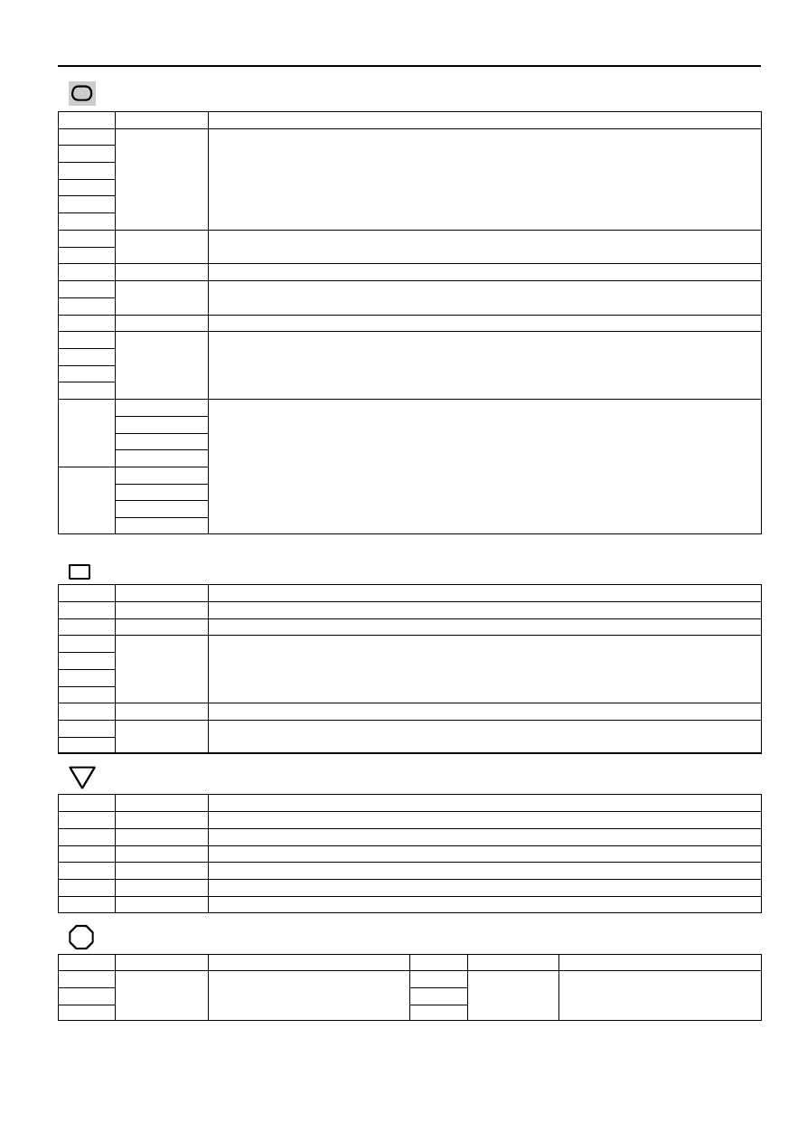
: Parts Location
Code
See Page
Code
See Page
Code
See Page
A4
E10
E
J1
A8
F8
J11
A13
A
H5
K2
A18
H10
B
M1
C1
I1
P1
C3
I2
S14
C7
A
I3
T3
C8
B
I4
V1
D3
I7
V4
E4
I8
V6
E6
A
I9
V7
E7
B
I10
V11
E8
C
I14
V12
E9
D
I15
: Relay Blocks
Code
See Page
Relay Blocks (Relay Block Location)
1
Engine Room R/B (Engine Compartment Left)
Service Hints
2002 CAMRY (EWD461U)
98
Engine Control (2AZ–FE)
: Junction Block and Wire Harness Connector
Code
See Page
Junction Block and Wire Harness (Connector Location)
1A
1B
1C
Engine Room Main Wire and Engine Room J/B (Engine Compartment Left)
1D
Engine Room Main Wire and Engine Room J/B (Engine Compartment Left)
1E
1H
1K
Engine Wire and Engine Room J/B (Engine Compartment Left)
1L
Engine Wire and Engine Room J/B (Engine Compartment Left)
2A
Instrument Panel Wire and Driver Side J/B (Lower Finish Panel)
2E
Engine Room Main Wire and Driver Side J/B (Lower Finish Panel)
2G
Engine Room Main Wire and Driver Side J/B (Lower Finish Panel)
2K
Floor Wire and Driver Side J/B (Lower Finish Panel)
2L
2M
Instrument Panel Wire and Driver Side J/B (Lower Finish Panel)
2O
Instrument Panel Wire and Driver Side J/B (Lower Finish Panel)
2R
3A
3A
Instrument Panel Wire and Passenger Side J/B (Instrument Panel Brace RH)
Instrument Panel Wire and Passenger Side J/B (Instrument Panel Brace RH)
3B
3B
∗
1 : TMC Made Automatic A/C
∗
2 : TMC Made Manual A/C
∗
3 : TMMK Made Automatic A/C
∗
4 : TMMK Made Manual A/C
: Connector Joining Wire Harness and Wire Harness
Code
See Page
Joining Wire Harness and Wire Harness (Connector Location)
IC2
Instrument Panel Wire and Floor Wire (Left Kick Panel)
ID1
Engine Room Main Wire and Floor Wire (Left Side of Driver Side J/B)
IF1
IF3
Engine Room Main Wire and Instrument Panel Wire (Right Side of Steering Column Tube)
IF4
Engine Room Main Wire and Instrument Panel Wire (Right Side of Steering Column Tube)
IF6
IJ1
Instrument Panel Wire and Instrument Panel Wire (Instrument Panel Reinforcement RH)
IL1
Engine Wire and Instrument Panel Wire (Behind the Glove Box)
IL2
Engine Wire and Instrument Panel Wire (Behind the Glove Box)
: Ground Points
Code
See Page
Ground Points Location
ED
Left Fender
EG
Left Side of Cylinder Head
EH
Intake Side of Cylinder Block
II
Cowl Side Panel LH
IJ
Instrument Panel Brace LH
BQ
Front Side of Rear Quarter Wheel House LH
: Splice Points
Code
See Page
Wire Harness with Splice Points
Code
See Page
Wire Harness with Splice Points
E13
I6
E14
Engine Wire
I7
Engine Wire
E15
g
I8
g

2002 CAMRY (EWD461U)
99
Memo
Wyszukiwarka
Podobne podstrony:
Engine Control I4
M31f1 Engine Controls 1 54
10 Engine Control System
Computer engine control
M31f4 Engine Controls 280 324
Cruise Control I4
ENGINE CONTROL SYSTEM
10 Engine Control System
M31f3 Engine Controls 152 279
Engine Control V6
Engine Control V6
M31f2 Engine Controls 55 151
M31f1 Engine Controls 1 54
10 Engine Control System
Computer engine control
M31f4 Engine Controls 280 324
więcej podobnych podstron