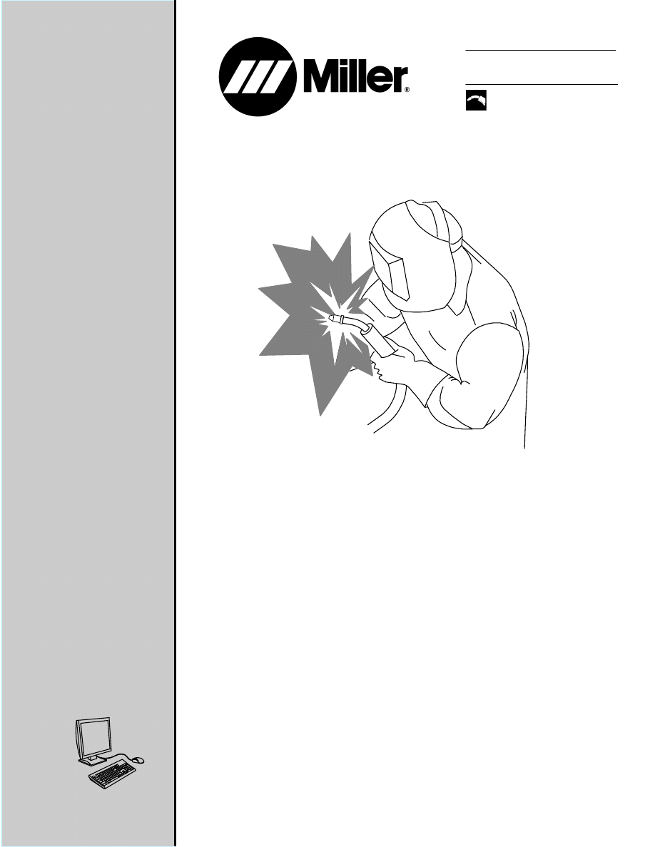
Processes
MIG (GMAW) Welding
154 557 C
2012−04
Guidelines For
Gas Metal Arc
Welding (GMAW)
Visit our website at
www.MillerWelds.com

TABLE OF CONTENTS
SECTION 1 − SAFETY PRECAUTIONS - READ BEFORE USING
1
. . . . . . . . . . . . . . . . . . . . . . . . . . . . . . . . . . .
1-1. Symbol Usage
1
. . . . . . . . . . . . . . . . . . . . . . . . . . . . . . . . . . . . . . . . . . . . . . . . . . . . . . . . . . . . . . . . . . . . . . . .
1-2. Arc Welding Hazards
1
. . . . . . . . . . . . . . . . . . . . . . . . . . . . . . . . . . . . . . . . . . . . . . . . . . . . . . . . . . . . . . . . . .
1-3. Additional Symbols For Installation, Operation, And Maintenance
3
. . . . . . . . . . . . . . . . . . . . . . . . . . . . .
1-4. California Proposition 65 Warnings
4
. . . . . . . . . . . . . . . . . . . . . . . . . . . . . . . . . . . . . . . . . . . . . . . . . . . . . . .
1-5. Principal Safety Standards
4
. . . . . . . . . . . . . . . . . . . . . . . . . . . . . . . . . . . . . . . . . . . . . . . . . . . . . . . . . . . . .
1-6. EMF Information
4
. . . . . . . . . . . . . . . . . . . . . . . . . . . . . . . . . . . . . . . . . . . . . . . . . . . . . . . . . . . . . . . . . . . . . .
SECTION 2 − GAS METAL ARC WELDING (GMAW)
. . . . . . . . . . . . . . . . . . . . . . . . . . . . . . . . . . . . . . . . . . . . . .
2-1. Typical GMAW Semiautomatic Setup With Constant Speed Feeder
. . . . . . . . . . . . . . . . . . . . . . . . . . .
2-2. Typical GMAW Semiautomatic Setup With Voltage-Sensing Feeder
. . . . . . . . . . . . . . . . . . . . . . . . . . .
2-3. Typical GMAW Process Control Settings
. . . . . . . . . . . . . . . . . . . . . . . . . . . . . . . . . . . . . . . . . . . . . . . . . .
2-4. Holding And Positioning Welding Gun
2-5. Conditions That Affect Weld Bead Shape
. . . . . . . . . . . . . . . . . . . . . . . . . . . . . . . . . . . . . . . . . . . . . . . . .
2-6. Gun Movement During Welding
2-7. Poor Weld Bead Characteristics
2-8. Good Weld Bead Characteristics
2-9. Common GMAW Shielding Gases
SECTION 3 − MODES OF GMAW TRANSFER
SECTION 4 − GMAW WELDING TROUBLESHOOTING
. . . . . . . . . . . . . . . . . . . . . . . . . . . . . . . . . . . . . . . . . . .
154 557 Page 1
SECTION 1 − SAFETY PRECAUTIONS - READ BEFORE USING
som 2011−10
7
Protect yourself and others from injury —
read, follow, and save these important safety precautions and operating instructions.
1-1. Symbol Usage
DANGER! − Indicates a hazardous situation which, if
not avoided, will result in death or serious injury. The
possible hazards are shown in the adjoining symbols
or explained in the text.
Indicates a hazardous situation which, if not avoided,
could result in death or serious injury. The possible
hazards are shown in the adjoining symbols or ex-
plained in the text.
NOTICE − Indicates statements not related to personal injury.
.
Indicates special instructions.
This group of symbols means Warning! Watch Out! ELECTRIC
SHOCK, MOVING PARTS, and HOT PARTS hazards. Consult sym-
bols and related instructions below for necessary actions to avoid the
hazards.
1-2. Arc Welding Hazards
The symbols shown below are used throughout this manual
to call attention to and identify possible hazards. When you
see the symbol, watch out, and follow the related instructions
to avoid the hazard. The safety information given below is
only a summary of the more complete safety information
found in the Safety Standards listed in Section 1-5. Read and
follow all Safety Standards.
Only qualified persons should install, operate, maintain, and
repair this unit.
During operation, keep everybody, especially children, away.
ELECTRIC SHOCK can kill.
Touching live electrical parts can cause fatal shocks
or severe burns. The electrode and work circuit is
electrically live whenever the output is on. The input
power circuit and machine internal circuits are also
live when power is on. In semiautomatic or automatic
wire welding, the wire, wire reel, drive roll housing,
and all metal parts touching the welding wire are
electrically live. Incorrectly installed or improperly
grounded equipment is a hazard.
D Do not touch live electrical parts.
D Wear dry, hole-free insulating gloves and body protection.
D Insulate yourself from work and ground using dry insulating mats
or covers big enough to prevent any physical contact with the work
or ground.
D Do not use AC output in damp areas, if movement is confined, or if
there is a danger of falling.
D Use AC output ONLY if required for the welding process.
D If AC output is required, use remote output control if present on
unit.
D Additional safety precautions are required when any of the follow-
ing electrically hazardous conditions are present: in damp
locations or while wearing wet clothing; on metal structures such
as floors, gratings, or scaffolds; when in cramped positions such
as sitting, kneeling, or lying; or when there is a high risk of unavoid-
able or accidental contact with the workpiece or ground. For these
conditions, use the following equipment in order presented: 1) a
semiautomatic DC constant voltage (wire) welder, 2) a DC manual
(stick) welder, or 3) an AC welder with reduced open-circuit volt-
age. In most situations, use of a DC, constant voltage wire welder
is recommended. And, do not work alone!
D Disconnect input power or stop engine before installing or
servicing this equipment. Lockout/tagout input power according to
OSHA 29 CFR 1910.147 (see Safety Standards).
D Properly install, ground, and operate this equipment according to
its Owner’s Manual and national, state, and local codes.
D Always verify the supply ground − check and be sure that input
power cord ground wire is properly connected to ground terminal in
disconnect box or that cord plug is connected to a properly
grounded receptacle outlet.
D When making input connections, attach proper grounding conduc-
tor first − double-check connections.
D Keep cords dry, free of oil and grease, and protected from hot metal
and sparks.
D Frequently inspect input power cord for damage or bare wiring −
replace cord immediately if damaged − bare wiring can kill.
D Turn off all equipment when not in use.
D Do not use worn, damaged, undersized, or poorly spliced cables.
D Do not drape cables over your body.
D If earth grounding of the workpiece is required, ground it directly
with a separate cable.
D Do not touch electrode if you are in contact with the work, ground,
or another electrode from a different machine.
D Do not touch electrode holders connected to two welding ma-
chines at the same time since double open-circuit voltage will be
present.
D Use only well-maintained equipment. Repair or replace damaged
parts at once. Maintain unit according to manual.
D Wear a safety harness if working above floor level.
D Keep all panels and covers securely in place.
D Clamp work cable with good metal-to-metal contact to workpiece
or worktable as near the weld as practical.
D Insulate work clamp when not connected to workpiece to prevent
contact with any metal object.
D Do not connect more than one electrode or work cable to any
single weld output terminal. Disconnect cable for process not in
use.
SIGNIFICANT DC VOLTAGE exists in inverter weld-
ing power sources AFTER removal of input power.
D Turn Off inverter, disconnect input power, and discharge input
capacitors according to instructions in Maintenance Section
before touching any parts.
HOT PARTS can burn.
D Do not touch hot parts bare handed.
D Allow cooling period before working on equip-
ment.
D To handle hot parts, use proper tools and/or
wear heavy, insulated welding gloves and
clothing to prevent burns.
154 557 Page 2
Welding produces fumes and gases. Breathing
these fumes and gases can be hazardous to your
health.
FUMES AND GASES can be hazardous.
D Keep your head out of the fumes. Do not breathe the fumes.
D If inside, ventilate the area and/or use local forced ventilation at the
arc to remove welding fumes and gases.
D If ventilation is poor, wear an approved air-supplied respirator.
D Read and understand the Material Safety Data Sheets (MSDSs)
and the manufacturer’s instructions for metals, consumables,
coatings, cleaners, and degreasers.
D Work in a confined space only if it is well ventilated, or while
wearing an air-supplied respirator. Always have a trained watch-
person nearby. Welding fumes and gases can displace air and
lower the oxygen level causing injury or death. Be sure the breath-
ing air is safe.
D Do not weld in locations near degreasing, cleaning, or spraying op-
erations. The heat and rays of the arc can react with vapors to form
highly toxic and irritating gases.
D Do not weld on coated metals, such as galvanized, lead, or
cadmium plated steel, unless the coating is removed from the weld
area, the area is well ventilated, and while wearing an air-supplied
respirator. The coatings and any metals containing these elements
can give off toxic fumes if welded.
Arc rays from the welding process produce intense
visible and invisible (ultraviolet and infrared) rays
that can burn eyes and skin. Sparks fly off from the
weld.
D Wear an approved welding helmet fitted with a proper shade of
filter lenses to protect your face and eyes from arc rays and
sparks when welding or watching (see ANSI Z49.1 and Z87.1
listed in Safety Standards).
D Wear approved safety glasses with side shields under your
helmet.
D Use protective screens or barriers to protect others from flash,
glare and sparks; warn others not to watch the arc.
D Wear protective clothing made from durable, flame-resistant
material (leather, heavy cotton, or wool) and foot protection.
ARC RAYS can burn eyes and skin.
Welding on closed containers, such as tanks,
drums, or pipes, can cause them to blow up. Sparks
can fly off from the welding arc. The flying sparks, hot
workpiece, and hot equipment can cause fires and
burns. Accidental contact of electrode to metal objects can cause
sparks, explosion, overheating, or fire. Check and be sure the area is
safe before doing any welding.
WELDING can cause fire or explosion.
D Remove all flammables within 35 ft (10.7 m) of the welding arc. If
this is not possible, tightly cover them with approved covers.
D Do not weld where flying sparks can strike flammable material.
D Protect yourself and others from flying sparks and hot metal.
D Be alert that welding sparks and hot materials from welding can
easily go through small cracks and openings to adjacent areas.
D Watch for fire, and keep a fire extinguisher nearby.
D Be aware that welding on a ceiling, floor, bulkhead, or partition can
cause fire on the hidden side.
D Do not weld on containers that have held combustibles, or on
closed containers such as tanks, drums, or pipes unless they are
properly prepared according to AWS F4.1 and AWS A6.0 (see
Safety Standards).
D Do not weld where the atmosphere may contain flammable dust,
gas, or liquid vapors (such as gasoline).
D Connect work cable to the work as close to the welding area as
practical to prevent welding current from traveling long, possibly
unknown paths and causing electric shock, sparks, and fire
hazards.
D Do not use welder to thaw frozen pipes.
D Remove stick electrode from holder or cut off welding wire at
contact tip when not in use.
D Wear oil-free protective garments such as leather gloves, heavy
shirt, cuffless trousers, high shoes, and a cap.
D Remove any combustibles, such as a butane lighter or matches,
from your person before doing any welding.
D After completion of work, inspect area to ensure it is free of sparks,
glowing embers, and flames.
D Use only correct fuses or circuit breakers. Do not oversize or by-
pass them.
D Follow requirements in OSHA 1910.252 (a) (2) (iv) and NFPA 51B
for hot work and have a fire watcher and extinguisher nearby.
FLYING METAL or DIRT can injure eyes.
D Welding, chipping, wire brushing, and grinding
cause sparks and flying metal. As welds cool,
they can throw off slag.
D Wear approved safety glasses with side
shields even under your welding helmet.
BUILDUP OF GAS can injure or kill.
D Shut off compressed gas supply when not in use.
D Always ventilate confined spaces or use
approved air-supplied respirator.
ELECTRIC AND MAGNETIC FIELDS (EMF)
can affect Implanted Medical Devices.
D Wearers of Pacemakers and other Implanted
Medical Devices should keep away.
D Implanted Medical Device wearers should consult their doctor
and the device manufacturer before going near arc welding, spot
welding, gouging, plasma arc cutting, or induction heating
operations.
NOISE can damage hearing.
Noise from some processes or equipment can
damage hearing.
D Wear approved ear protection if noise level is
high.
Compressed gas cylinders contain gas under high
pressure. If damaged, a cylinder can explode. Since
gas cylinders are normally part of the welding
process, be sure to treat them carefully.
CYLINDERS can explode if damaged.
D Protect compressed gas cylinders from excessive heat, mechani-
cal shocks, physical damage, slag, open flames, sparks, and arcs.
D Install cylinders in an upright position by securing to a stationary
support or cylinder rack to prevent falling or tipping.
D Keep cylinders away from any welding or other electrical circuits.
D Never drape a welding torch over a gas cylinder.
D Never allow a welding electrode to touch any cylinder.
D Never weld on a pressurized cylinder − explosion will result.
D Use only correct compressed gas cylinders, regulators, hoses,
and fittings designed for the specific application; maintain them
and associated parts in good condition.
D Turn face away from valve outlet when opening cylinder valve.
D Keep protective cap in place over valve except when cylinder is in
use or connected for use.
D Use the right equipment, correct procedures, and sufficient num-
ber of persons to lift and move cylinders.
D Read and follow instructions on compressed gas cylinders,
associated equipment, and Compressed Gas Association (CGA)
publication P-1 listed in Safety Standards.
154 557 Page 3
1-3. Additional Symbols For Installation, Operation, And Maintenance
FIRE OR EXPLOSION hazard.
D Do not install or place unit on, over, or near
combustible surfaces.
D Do not install unit near flammables.
D Do not overload building wiring − be sure power supply system is
properly sized, rated, and protected to handle this unit.
FALLING EQUIPMENT can injure.
D Use lifting eye to lift unit only, NOT running
gear, gas cylinders, or any other accessories.
D Use equipment of adequate capacity to lift and
support unit.
D If using lift forks to move unit, be sure forks are long enough to
extend beyond opposite side of unit.
D Keep equipment (cables and cords) away from moving vehicles
when working from an aerial location.
D Follow the guidelines in the Applications Manual for the Revised
NIOSH Lifting Equation (Publication No. 94−110) when manu-
ally lifting heavy parts or equipment.
OVERUSE can cause OVERHEATING
D Allow cooling period; follow rated duty cycle.
D Reduce current or reduce duty cycle before
starting to weld again.
D Do not block or filter airflow to unit.
FLYING SPARKS can injure.
D Wear a face shield to protect eyes and face.
D Shape tungsten electrode only on grinder with
proper guards in a safe location wearing proper
face, hand, and body protection.
D Sparks can cause fires — keep flammables away.
STATIC (ESD) can damage PC boards.
D Put on grounded wrist strap BEFORE handling
boards or parts.
D Use proper static-proof bags and boxes to
store, move, or ship PC boards.
MOVING PARTS can injure.
D Keep away from moving parts.
D Keep away from pinch points such as drive
rolls.
WELDING WIRE can injure.
D Do not press gun trigger until instructed to do
so.
D Do not point gun toward any part of the body,
other people, or any metal when threading
welding wire.
BATTERY EXPLOSION can injure.
D Do not use welder to charge batteries or jump
start vehicles unless it has a battery charging
feature designed for this purpose.
MOVING PARTS can injure.
D Keep away from moving parts such as fans.
D Keep all doors, panels, covers, and guards
closed and securely in place.
D Have only qualified persons remove doors, panels, covers, or
guards for maintenance and troubleshooting as necessary.
D Reinstall doors, panels, covers, or guards when maintenance is
finished and before reconnecting input power.
READ INSTRUCTIONS.
D Read and follow all labels and the Owner’s
Manual carefully before installing, operating, or
servicing unit. Read the safety information at
the beginning of the manual and in each
section.
D Use only genuine replacement parts from the manufacturer.
D Perform maintenance and service according to the Owner’s
Manuals, industry standards, and national, state, and local
codes.
H.F. RADIATION can cause interference.
D High-frequency (H.F.) can interfere with radio
navigation, safety services, computers, and
communications equipment.
D Have only qualified persons familiar with
electronic equipment perform this installation.
D The user is responsible for having a qualified electrician prompt-
ly correct any interference problem resulting from the installa-
tion.
D If notified by the FCC about interference, stop using the
equipment at once.
D Have the installation regularly checked and maintained.
D Keep high-frequency source doors and panels tightly shut, keep
spark gaps at correct setting, and use grounding and shielding to
minimize the possibility of interference.
ARC WELDING can cause interference.
D Electromagnetic energy can interfere with
sensitive electronic equipment such as
computers and computer-driven equipment
such as robots.
D Be sure all equipment in the welding area is
electromagnetically compatible.
D To reduce possible interference, keep weld cables as short as
possible, close together, and down low, such as on the floor.
D Locate welding operation 100 meters from any sensitive elec-
tronic equipment.
D Be sure this welding machine is installed and grounded
according to this manual.
D If interference still occurs, the user must take extra measures
such as moving the welding machine, using shielded cables,
using line filters, or shielding the work area.

154 557 Page 4
1-4. California Proposition 65 Warnings
Welding or cutting equipment produces fumes or gases
which contain chemicals known to the State of California to
cause birth defects and, in some cases, cancer. (California
Health & Safety Code Section 25249.5 et seq.)
This product contains chemicals, including lead, known to
the state of California to cause cancer, birth defects, or other
reproductive harm. Wash hands after use.
1-5. Principal Safety Standards
Safety in Welding, Cutting, and Allied Processes, ANSI Standard Z49.1,
is available as a free download from the American Welding Society at
http://www.aws.org or purchased from Global Engineering Documents
(phone: 1-877-413-5184, website: www.global.ihs.com).
Safe Practices for the Preparation of Containers and Piping for Welding
and Cutting, American Welding Society Standard AWS F4.1, from Glob-
al Engineering Documents (phone: 1-877-413-5184, website:
www.global.ihs.com).
Safe Practices for Welding and Cutting Containers that have Held Com-
bustibles, American Welding Society Standard AWS A6.0, from Global
Engineering Documents (phone: 1-877-413-5184,
website: www.global.ihs.com).
National Electrical Code, NFPA Standard 70, from National Fire Protec-
tion Association, Quincy, MA 02269 (phone: 1-800-344-3555, website:
www.nfpa.org and www. sparky.org).
Safe Handling of Compressed Gases in Cylinders, CGA Pamphlet P-1,
from Compressed Gas Association, 14501 George Carter Way, Suite
103, Chantilly, VA 20151 (phone: 703-788-2700, website:www.cga-
net.com).
Safety in Welding, Cutting, and Allied Processes, CSA Standard
W117.2, from Canadian Standards Association, Standards Sales, 5060
Spectrum Way, Suite 100, Ontario, Canada L4W 5NS (phone:
800-463-6727, website: www.csa-international.org).
Safe Practice For Occupational And Educational Eye And Face Protec-
tion, ANSI Standard Z87.1, from American National Standards Institute,
25 West 43rd Street, New York, NY 10036 (phone: 212-642-4900, web-
site: www.ansi.org).
Standard for Fire Prevention During Welding, Cutting, and Other Hot
Work, NFPA Standard 51B, from National Fire Protection Association,
Quincy, MA 02269 (phone: 1-800-344-3555, website: www.nfpa.org.
OSHA, Occupational Safety and Health Standards for General Indus-
try, Title 29, Code of Federal Regulations (CFR), Part 1910, Subpart Q,
and Part 1926, Subpart J, from U.S. Government Printing Office, Super-
intendent of Documents, P.O. Box 371954, Pittsburgh, PA 15250-7954
(phone: 1-866-512-1800) (there are 10 OSHA Regional Offices—
phone for Region 5, Chicago, is 312-353-2220, website:
www.osha.gov).
Applications Manual for the Revised NIOSH Lifting Equation, The Na-
tional Institute for Occupational Safety and Health (NIOSH), 1600
Clifton Rd, Atlanta, GA 30333 (phone: 1-800-232-4636, website:
www.cdc.gov/NIOSH).
1-6. EMF Information
Electric current flowing through any conductor causes localized electric
and magnetic fields (EMF). Welding current creates an EMF field
around the welding circuit and welding equipment. EMF fields may inter-
fere with some medical implants, e.g. pacemakers. Protective
measures for persons wearing medical implants have to be taken. For
example, restrict access for passers−by or conduct individual risk as-
sessment for welders. All welders should use the following procedures
in order to minimize exposure to EMF fields from the welding circuit:
1. Keep cables close together by twisting or taping them, or using a
cable cover.
2. Do not place your body between welding cables. Arrange cables
to one side and away from the operator.
3. Do not coil or drape cables around your body.
4. Keep head and trunk as far away from the equipment in the
welding circuit as possible.
5. Connect work clamp to workpiece as close to the weld as
possible.
6. Do not work next to, sit or lean on the welding power source.
7. Do not weld whilst carrying the welding power source or wire
feeder.
About Implanted Medical Devices:
Implanted Medical Device wearers should consult their doctor and the
device manufacturer before performing or going near arc welding, spot
welding, gouging, plasma arc cutting, or induction heating operations.
If cleared by your doctor, then following the above procedures is recom-
mended.

154 557 Page 5
SECTION 2 − GAS METAL ARC WELDING (GMAW)
Gas Metal Arc Welding (GMAW) is a welding process which joins metals by heating the metals to their melting point
with an electric arc. The arc is between a continuous, consumable electrode wire and the metal being welded. The
arc is shielded from contaminants in the atmosphere by a shielding gas.
GMAW can be done in three different ways:
S Semiautomatic Welding - equipment controls only the electrode wire feeding. Movement of welding gun is controlled
by hand. This may be called hand-held welding.
S Machine Welding - uses a gun that is connected to a manipulator of some kind (not hand-held). An operator has
to constantly set and adjust controls that move the manipulator.
S Automatic Welding - uses equipment which welds without the constant adjusting of controls by a welder or operator.
On some equipment, automatic sensing devices control the correct gun alignment in a weld joint.
Basic equipment for a typical GMAW semiautomatic setup:
S Welding Power Source - provides welding power.
S Wire Feeders (Constant Speed And Voltage-Sensing) - controls supply of wire to welding gun.
Constant Speed Feeder - Used only with a constant voltage (CV) power source. This type of feeder has a control
cable that will connect to the power source. The control cable supplies power to the feeder and allows the capability
of remote voltage control with certain power source/feeder combinations. The wire feed speed (WFS) is set on the
feeder and will always be constant for a given preset value.
Voltage-Sensing Feeder - Can be used with either a constant voltage (CV) or constant current (CC) - direct current
(DC) power source. This type of feeder is powered off of the arc voltage and does not have a control cord. When
set to (CV), the feeder is similar to a constant speed feeder. When set to (CC), the wire feed speed depends on
the voltage present. The feeder changes the wire feed speed as the voltage changes. A voltage sensing feeder
does not have the capability of remote voltage control.
S Supply of Electrode Wire.
S Welding Gun - delivers electrode wire and shielding gas to the weld puddle.
S Shielding Gas Cylinder - provides a supply of shielding gas to the arc.
154 557 Page 6
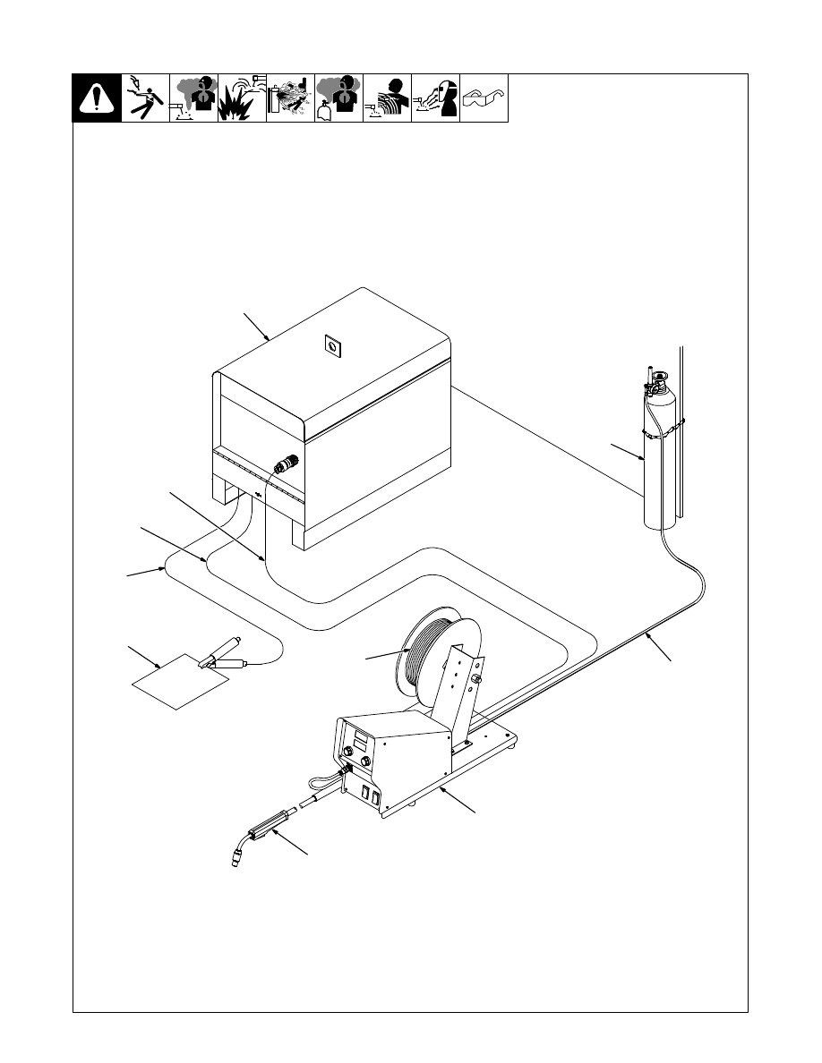
2-1. Typical GMAW Semiautomatic Setup With Constant Speed Feeder
1
Constant Voltage (CV)
Welding Power Source
2
Contactor Control/Power Cord
3
Weld Cable To Feeder
4
Ground Cable To Workpiece
5
Workpiece
6
Welding Gun
7
Constant Speed Wire Feeder
8
Electrode Wire
9
Gas Hose
10 Shielding Gas Cylinder
804 656-A
1
2
3
4
5
7
9
10
8
6
154 557 Page 7
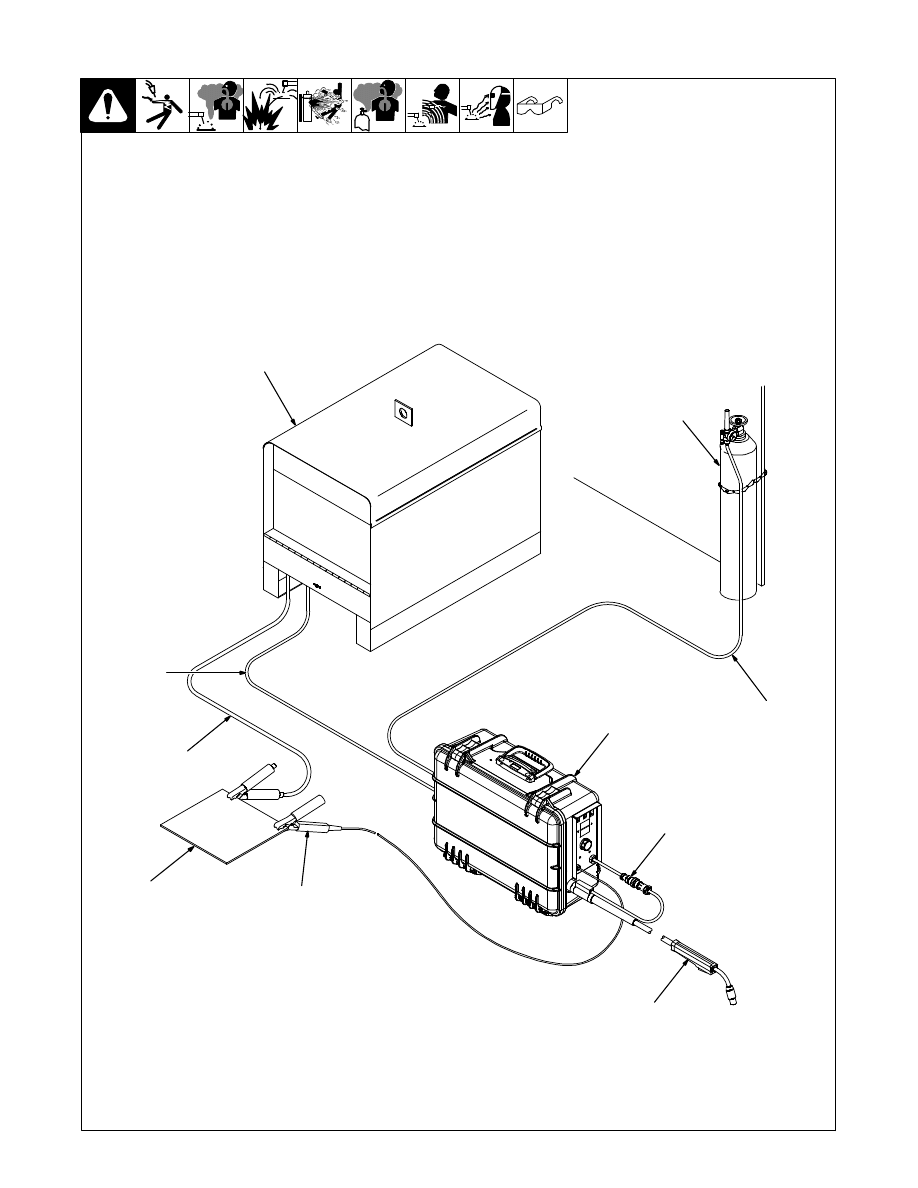
2-2. Typical GMAW Semiautomatic Setup With Voltage-Sensing Feeder
Ref. 804 000-C
1
2
3
4
8
9
10
6
7
5
1
Constant Current (CC-DC) Or
Constant Voltage (CV)
Welding Power Source
2
Weld Cable To Feeder
3
Ground Cable To Workpiece
4
Workpiece
5
Voltage-Sensing Clamp
6
Welding Gun
7
Gun Trigger Receptacle
8
Voltage-Sensing Wire Feeder
9
Gas Hose
10 Shielding Gas Cylinder
154 557 Page 8
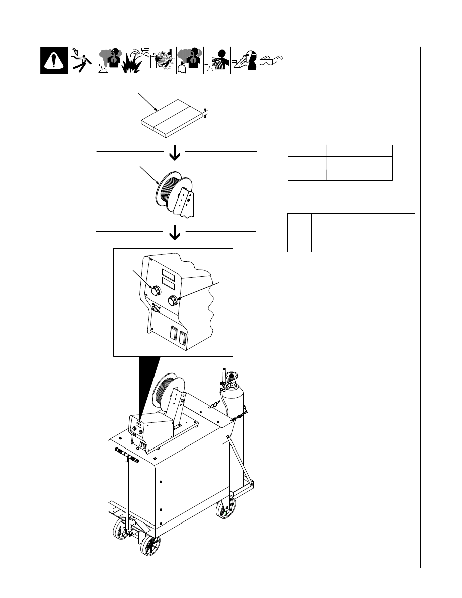
2-3. Typical GMAW Process Control Settings
.
These settings are guidelines only. Material
and wire type, joint design, fit−up, position,
shielding gas, etc. affect settings. Test welds
to be sure they comply to specifications.
1
Convert Material Thickness to
Amperage (A)
(.001 in. = 1 ampere)
.125 = 125 A
.
Material thickness determines weld
parameters.
2
Select Wire Size
3
Select Wire Speed (Amperage)
125 A based on 1/8 in. (3 mm) material thickness.
(ipm = inch per minute)
.
Wire speed (amperage) controls weld pene-
tration (wire speed = burn-off rate).
4
Select Voltage
Low Voltage: wire stubs into work
High Voltage: arc is unstable (spatter)
Set voltage midway between high/low voltage.
.
Voltage controls height and width of weld
bead.
802 806-A / 800 354
1/8 or
.125 in.
Wire
Suggested
.030 in.
.035 in.
.045 in.
2 in. per amp
1.6 in. per amp
1 in. per amp
Wire Speed
2 x 125 A = 250 IPM
1.6 x 125 A = 200 IPM
1 x 125 A = 125 IPM
Size
(Approx.)
Amperage Range
40 − 145 A
50 − 180 A
75 − 250 A
Wire Size
.030 in.
.035 in.
.045 in.
2
1
3
4
154 557 Page 9
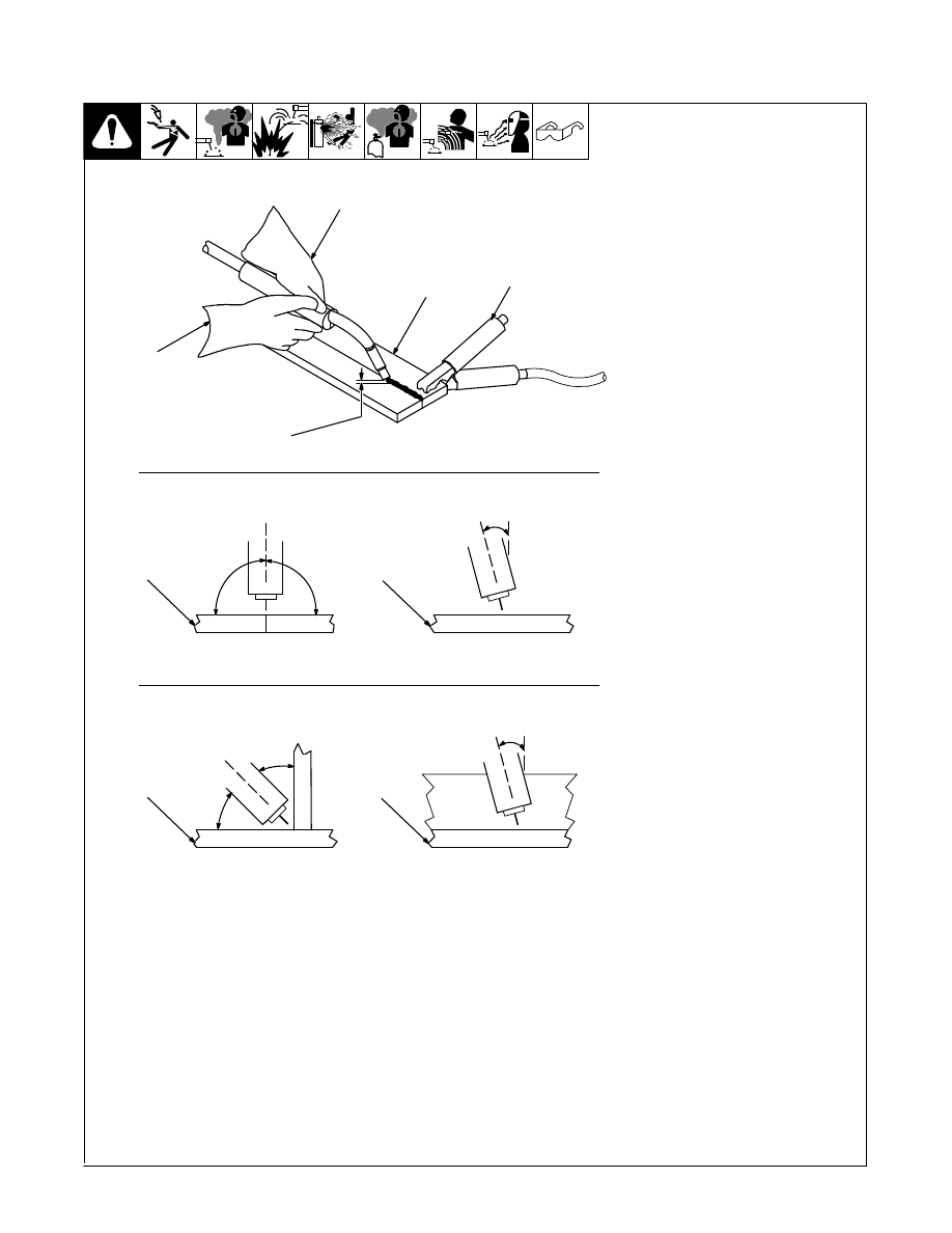
2-4. Holding And Positioning Welding Gun
S-0421-A
.
Welding wire is energized when
gun trigger is pressed. Before
lowering helmet and pressing
trigger, be sure wire is no more
than 1/2 in. (13 mm) past end of
nozzle, and tip of wire is posi-
tioned correctly on seam.
1
Hold Gun And Control Gun
Trigger
2
Workpiece
3
Work Clamp
4
Electrode Extension (Stickout)
1/4 To 1/2 in. (6 To 13 mm)
5
Cradle Gun And Rest Hand On
Workpiece
Groove Welds
6
End View Of Work Angle
7
Side View Of Gun Angle
Fillet Welds
8
End View Of Work Angle
9
Side View Of Gun Angle
2
3
5
4
90
90
0
-15
45
45
1
0
-15
6
7
8
9
154 557 Page 10
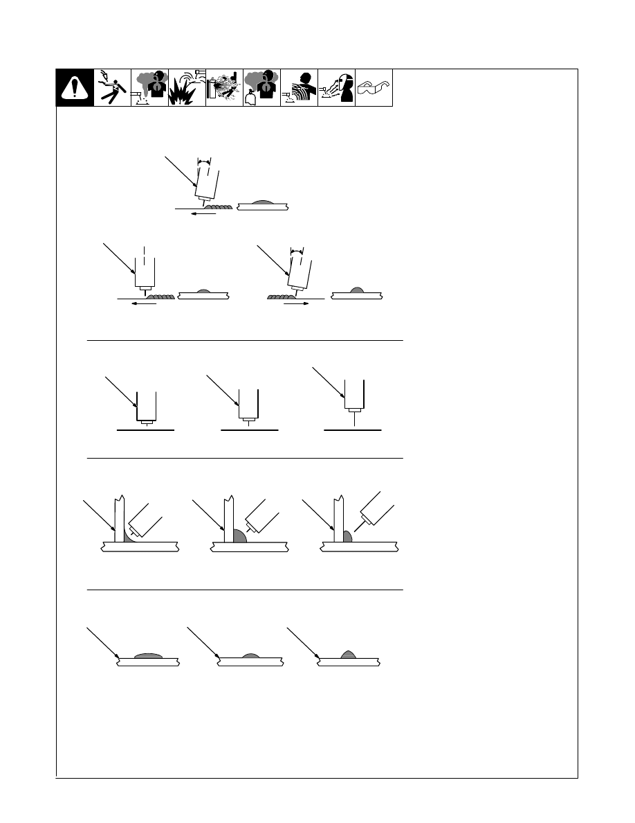
2-5. Conditions That Affect Weld Bead Shape
S-0634-A
.
Weld bead shape depends on
gun angle, direction of travel,
electrode extension (stickout),
travel speed, thickness of base
metal, wire feed speed (weld
current), and voltage.
Gun Angles And Weld Bead
Profiles
1
Push
2
Perpendicular
3
Drag
Electrode Extensions (Stickout)
4
Short
5
Normal
6
Long
Fillet Weld Electrode Extension
(Stickout)
7
Short
8
Normal
9
Long
Gun Travel Speed
10 Slow
11 Normal
12 Fast
10
10
1
2
3
5
4
6
7
8
9
10
11
12
154 557 Page 11
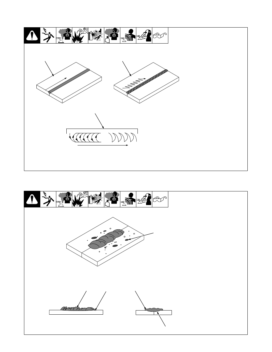
2-6. Gun Movement During Welding
.
Normally, a single stringer bead
is satisfactory for most narrow
groove weld joints. However, for
wide groove weld joints or bridg-
ing across gaps, a weave bead
or multiple stringer beads works
better.
1
Stringer Bead − Steady Move-
ment Along Seam
2
Weave Bead − Side To Side
Movement Along Seam
3
Weave Patterns
Use weave patterns to cover a wide
area in one pass of the electrode.
S-0054-A
1
2
3
2-7. Poor Weld Bead Characteristics
S-0053-A
1
Large Spatter Deposits
2
Rough, Uneven Bead
3
Slight Crater During Welding
4
Bad Overlap
5
Poor Penetration
5
4
2
3
1
154 557 Page 12
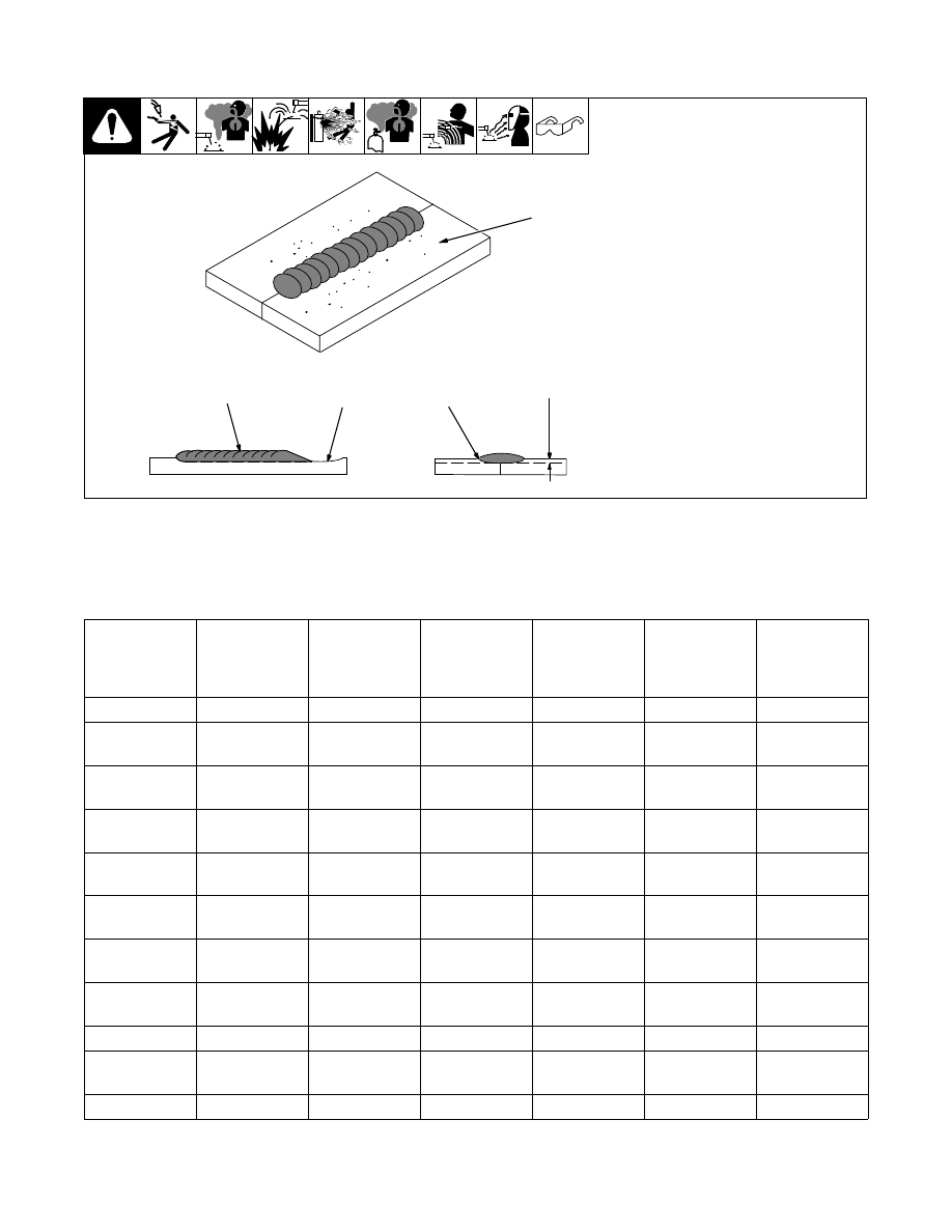
2-8. Good Weld Bead Characteristics
S-0052-B
1
Fine Spatter Or No Spatter
2
Uniform Bead
3
Moderate Crater During
Welding
4
No Overlap
5
Good Penetration Into Base
Metal
2
3
4
1
5
2-9. Common GMAW Shielding Gases
This is a general chart for common gases and where they are used. Many different combinations (mixtures) of shield-
ing gases have been developed over the years.
Gas
Spray Arc
Steel
Short
Circuiting
Steel
Spray Arc
Stainless Steel
Short
Circuiting
Stainless
Steel
Spray Arc
Aluminum
Short
Circuiting
Aluminum
Argon
All Positions
5
All Positions
Argon + 1% O
2
Flat & Horizontal
5
Fillet
Flat & Horizontal
5
Fillet
Argon + 2% O
2
Flat & Horizontal
5
Fillet
Flat & Horizontal
5
Fillet
Argon + 5% O
2
Flat & Horizontal
5
Fillet
Argon + 8%
CO
2
Flat & Horizontal
5
Fillet
All Positions
Argon + 25%
CO
2
Flat & Horizontal
1
Fillet
All Positions
Argon + 50%
CO
2
All Positions
CO
2
Flat & Horizontal
1
Fillet
All Positions
Helium
All Positions
2
Argon +
Helium
All Positions
2
Tri-Mix
4
All Positions
1
Globular Transfer
4
90% HE + 7-1/2% AR + 2-1/2% CO
2
2
Heavy Thicknesses
5
Also for GMAW-P, All Positions
3
Single Pass Welding Only
154 557 Page 13
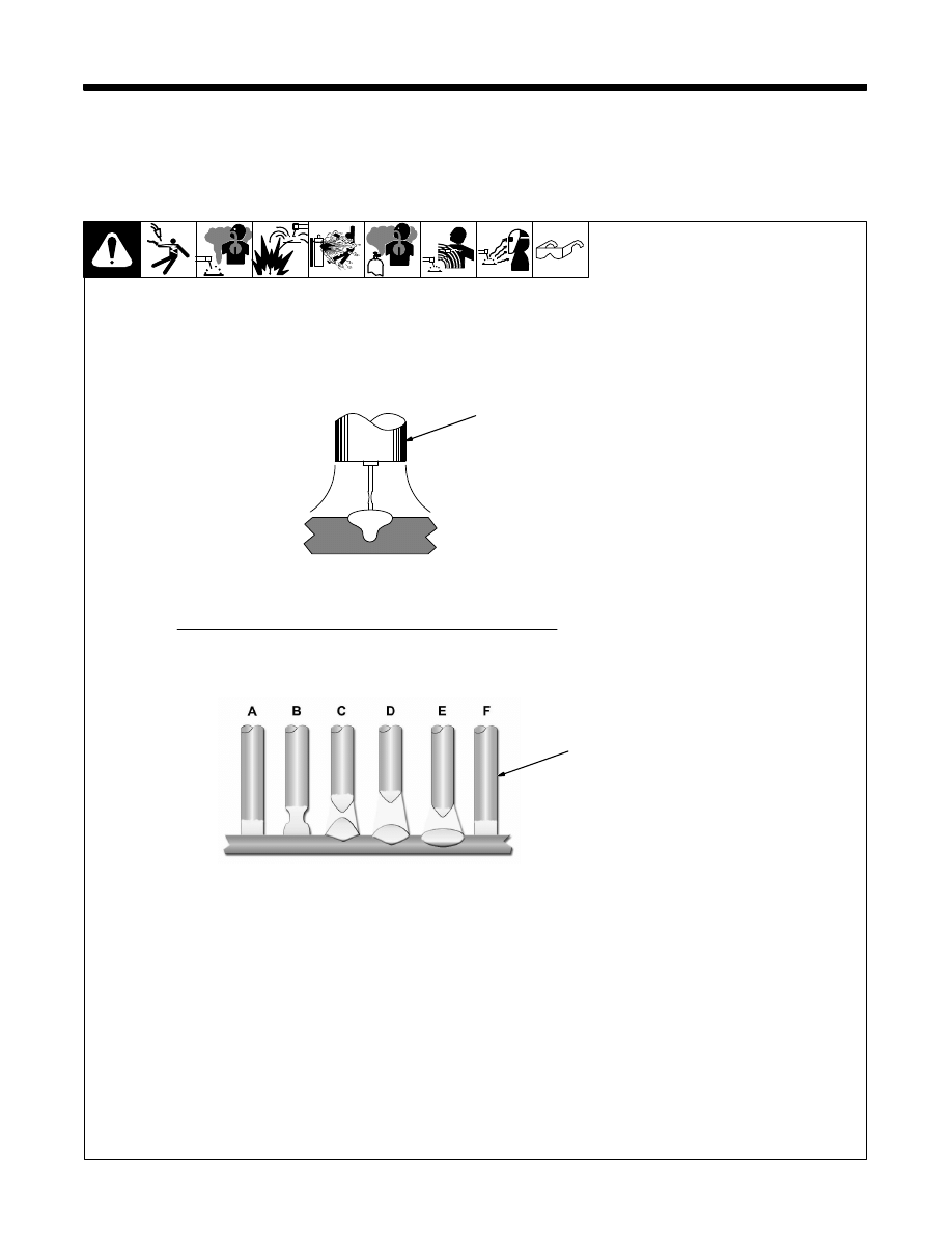
SECTION 3 − MODES OF GMAW TRANSFER
.
GMAW transfer mode is determined by variables such as shielding gas type, arc voltage, arc current, diameter of electrode and wire feed speed.
3-1. Short Circuit Transfer
1
Short Circuit Transfer
Short circuit transfer refers to the
welding wire actually “short circuit-
ing” (touching) the base metal be-
tween 90 - 200 times per second.
With short circuit transfer, wire feed
speeds, voltages, and deposition
rates are usually lower than with oth-
er types of metal transfer such as
spray transfer. This makes short cir-
cuit transfer very versatile allowing
the welder to weld on thin or thick
metals in any position.
Limitations of short circuit transfer:
S A relatively low deposition rate
S Lack of fusion on thicker metals
S More spatter
.
Short circuit transfer usually has
a crackling (bacon frying) sound
when a good condition exists.
2
Short Circuit Cycle
A - Electrode is short circuited to
base metal. No arc, and current
is flowing through electrode
wire and base metal.
B - Resistance increases in elec-
trode wire causing it to heat,
melt and “neck down”.
C - Electrode wire separates from
weld puddle, creating an arc.
Small portion of electrode wire
is deposited which forms a
weld puddle.
D - Arc length and load voltage are
at maximum. Heat of arc is flat-
tening the puddle and increas-
ing the diameter tip of elec-
trode.
E - Wire feed speed overcomes
heat of arc and wire
approaches base metal again.
F - Arc is off and the short circuit
cycle starts again.
1
2
Ref. 804 879-A
154 557 Page 14
3-2. Globular Transfer
1
Globular Transfer
Globular transfer refers to the state of
transfer between short-circuiting and
spray arc transfer. Large globs of
wire are expelled off the end of the
electrode wire and enter the weld
puddle.
Globular transfer can result when
welding parameters such as voltage,
amperage and wire feed speed are
somewhat higher than the settings
for short circuit transfer.
Limitations of globular transfer:
S Presence of spatter
S Less desirable weld appearance
than spray arc transfer
S Welding is limited to flat positions
and horizontally fillet welds
S Welding is limited to metal 1/8 inch
(3 mm)or thicker
1
Ref. 804 879-A
3-3. Spray Arc Transfer
1
Spray Arc Transfer
Spray arc transfer “sprays” a stream
of tiny molten droplets across the
arc, from the electrode wire to the
base metal.
Spray arc transfer uses relatively
high voltage, wire feed speed and
amperage values, compared to short
circuit transfer.
.
To achieve a true spray transfer,
an argon-rich shielding gas must
be used.
When proper parameters are used,
the spray arc transfer produces a
characteristic humming or buzzing
sound.
Advantages of spray arc transfer:
S High deposition
S Good fusion and penetration
S Good bead appearance
S Capability of using larger diameter
wires
S Presence of very little spatter
Limitations of spray arc transfer:
S Used only on material 1/8 inch
(3 mm) and thicker (hand held)
S Limited to flat and horizontal fillet
weld position (except for some spray
transfer on aluminum)
S Good fit-up is always required as
there is no open root capability
1
Ref. 804 879-A
154 557 Page 15
SECTION 4 − GMAW WELDING TROUBLESHOOTING
4-1. Excessive Spatter
Excessive Spatter − scattering of
molten metal particles that cool to
solid form near weld bead.
Possible Causes
Corrective Actions
Wire feed speed too high.
Select lower wire feed speed.
Voltage too high.
Select lower voltage range.
Electrode extension (stickout) too long. Use shorter electrode extension (stickout).
Workpiece dirty.
Remove all grease, oil, moisture, rust, paint, undercoating, and dirt from work surface before welding.
Insufficient shielding gas at welding
arc.
Increase flow of shielding gas at regulator/flowmeter and/or prevent drafts near welding arc.
Dirty welding wire.
Use clean, dry welding wire.
Eliminate pickup of oil or lubricant on welding wire from feeder or liner.
4-2. Porosity
Porosity − small cavities or holes
resulting from gas pockets in weld
metal.
Possible Causes
Corrective Actions
Inadequate shielding gas coverage.
Check for proper gas flow rate.
Remove spatter from gun nozzle.
Check gas hoses for leaks.
Eliminate drafts near welding arc.
Place nozzle 1/4 to 1/2 in. (6-13 mm) from workpiece.
Hold gun near bead at end of weld until molten metal solidifies.
Wrong gas.
Use welding grade shielding gas; change to different gas.
Dirty welding wire.
Use clean, dry welding wire.
Eliminate pick up of oil or lubricant on welding wire from feeder or liner.
Workpiece dirty.
Remove all grease, oil, moisture, rust, paint, coatings, and dirt from work surface before welding.
Use a more highly deoxidizing welding wire (contact supplier).
Welding wire extends too far out of
nozzle.
Be sure welding wire extends not more than 1/2 in. (13 mm) beyond nozzle.
154 557 Page 16
4-3. Incomplete Fusion
Incomplete Fusion − failure of weld
metal to fuse completely with base
metal or a preceeding weld bead.
Possible Causes
Corrective Actions
Workpiece dirty.
Remove all grease, oil, moisture, rust, paint, coatings, and dirt from work surface before welding.
Insufficient heat input.
Select higher voltage range and/or adjust wire feed speed.
Improper welding technique.
Place stringer bead in proper location(s) at joint during welding.
Adjust work angle or widen groove to access bottom during welding.
Momentarily hold arc on groove side walls when using weaving technique.
Keep arc on leading edge of weld puddle.
Use correct gun angle of 0 to 15 degrees.
4-4. Excessive Penetration
Good Penetration
Excessive Penetration − weld metal
melting through base metal and
hanging underneath weld.
Excessive Penetration
Possible Causes
Corrective Actions
Excessive heat input.
Select lower voltage range and reduce wire feed speed.
Increase travel speed.
4-5. Lack Of Penetration
Lack Of Penetration − shallow
fusion between weld metal and
base metal.
Lack of Penetration
Good Penetration
Possible Causes
Corrective Actions
Improper joint preparation.
Material too thick. Joint preparation and design must provide access to bottom of groove while main-
taining proper welding wire extension and arc characteristics.
Improper weld technique.
Maintain normal gun angle of 0 to 15 degrees to achieve maximum penetration.
Keep arc on leading edge of weld puddle.
Be sure welding wire extends not more than 1/2 in. (13 mm) beyond nozzle.
Insufficient heat input.
Select higher wire feed speed and/or select higher voltage range.
Reduce travel speed.
154 557 Page 17
4-6. Burn Through
Burn-Through − weld metal melting
completely through base metal
resulting in holes where no metal re-
mains.
Possible Causes
Corrective Actions
Excessive heat input.
Select lower voltage range and reduce wire feed speed.
Increase and/or maintain steady travel speed.
4-7. Waviness Of Bead
Waviness Of Bead − weld metal that
is not parallel and does not cover
joint formed by base metal.
Possible Causes
Corrective Actions
Unsteady hand.
Support hand on solid surface or use two hands.
4-8. Distortion
Distortion − contraction of weld met-
al during welding that forces base
metal to move.
Base metal moves
in the direction of
the weld bead.
Possible Causes
Corrective Actions
Excessive heat input.
Use restraint (clamp) to hold base metal in position.
Make tack welds along joint before starting welding operation.
Select lower voltage range and/or reduce wire feed speed.
Increase travel speed.
Weld in small segments and allow cooling between welds.

ORIGINAL INSTRUCTIONS − PRINTED IN USA
2012 Miller Electric Mfg. Co.
Miller Electric Mfg. Co.
An Illinois Tool Works Company
1635 West Spencer Street
Appleton, WI 54914 USA
International Headquarters−USA
USA Phone: 920-735-4505 Auto-Attended
USA & Canada FAX: 920-735-4134
International FAX: 920-735-4125
For International Locations Visit
www.MillerWelds.com
Wyszukiwarka
Podobne podstrony:
Guidelines to Gas Tungsten Arc Welding (GTAW)
Guidelines for Shielded Metal Arc (Stick) Welding (SMAW)
Paralleling Arc Welding Power Sources
Performance Improvements in an arc welding power supply based on resonant inverters (1)
Paralleling Arc Welding Power Sources
kody do Hard Truck Pedal to the metal
Solid phase microextraction coupled to gas chromatography a
HHO Browns Gas Arc Assisted Oxy Hydrogen Welding Invented By Yull Brown
Access to History 001 Gas Attack! The Canadians at Ypres, 1915
Perceived risk and adherence to breast cancer screening guidelines
Zanieczyszczenia i szkodliwosc, Azbest, Azbest - ogólna nazwa minerałów z grupy amfiboli i serpentyn
Zanieczyszczenia i szkodliwosc, Azbest, Azbest - ogólna nazwa minerałów z grupy amfiboli i serpentyn
Magiczne przygody kubusia puchatka 29 WELCOME TO THE GAS WORKS
Access to History 001 Gas Attack! The Canadians at Ypres, 1915
Energy and Fuels 2006, 20, 155 158, Novel Process for Recycling Waste Plastics To Fuel Gas Using a M
więcej podobnych podstron