42
elektor - 11/2008
Tracking Hot Spots
Monitoring
infrared sources
with the
Mega88
Udo Jürsz and Wolfgang Rudolph (Germany)
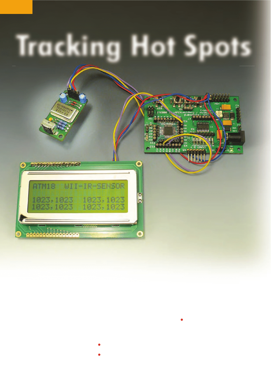
In this instalment, we add a miniature infrared camera with integrated image processing capability to
the ATM18 system. This makes it possible to identify the positions of up to four infrared sources, display
the positions on a monitor, and output their coordinates. Assembling a high-tech camera system of this
sort is certainly affordable if you take advantage of mass-produced high-tech toys.
When you hear the term ‘hot spot’, you
probably think of a wireless Internet
access point, but this term also has
other meanings. In a nuclear power
plant it means a tiny, highly radioac-
tive particle; in a database it means a
data element; and in geology it means
a centre of volcanic activity.
However, the hot spots we are have in
mind here are literally hot locations.
Anything that is hot emits infrared
radiation. There are three generally rec-
ognised classes of infrared radiation:
•
IR-A covers the range from 0.78
µm
to 1.4
µm;
•
IR-B covers the range from 1.4
µm to
3
µm;
•
IR-C covers the range from 3
µm to
1
µm.
The terms ‘thermal radiation’ and
‘infrared radiation’ are often confused
with each other. Thermal radiation is
the electromagnetic radiation emit-
ted by a body as a function of its tem-
perature. Infrared radiation occupies
PROJECTS
MICROCONTROLLERS
43
11/2008 - elektor
Tracking Hot Spots
only a small portion of the total ther-
mal radiation spectrum. For the pur-
poses of the present project, the IR-A
range is especially interesting because
we intend to use a tiny camera that
is fitted with an optical filter so it can
only see light in the range of 850
nm to
920
nm, and which has integrated sig-
nal processing circuitry. Such a compo-
nent can provide the basis for innumer-
able applications, such as a fire alarm,
an intrusion alarm, an object tracker,
a gesture-controlled input device, an
instrument for measuring the speed of
objects, and much more. But how can
you get your hands on this sort of high-
tech camera?
Interesting sensors
By the end of 2007, Nintendo had
already sold more than 15
million Wii
game consoles. As a result, the asso-
ciated remote game controller (Wii
Remote), often referred to as ‘Wii-
mote’ (Figure
1), has become a very
widely used computer input device
[1]. Among other things, it includes
an infrared camera with a resolu-
tion of 1024
r 768 pixels and built-in
hardware blob tracking for up to four
objects at the same time. This CMOS
camera sensor, which is made by Pix-
Art Technologies [2], is in a different
league than your average PC-compat-
ible webcam. The Wiimote also con-
tains a three-axis acceleration sensor
(Analog Devices ADX330 [3]) with a
resolution of 8
bits and a measuring
range of ±3
g. The remote control unit
is a fascinating piece of technology,
and on top of this it is quite inexpen-
sive. You can pick one up from various
dealers or online auctions for less than
£
20 (` 25) or at least you could before
this article was published!
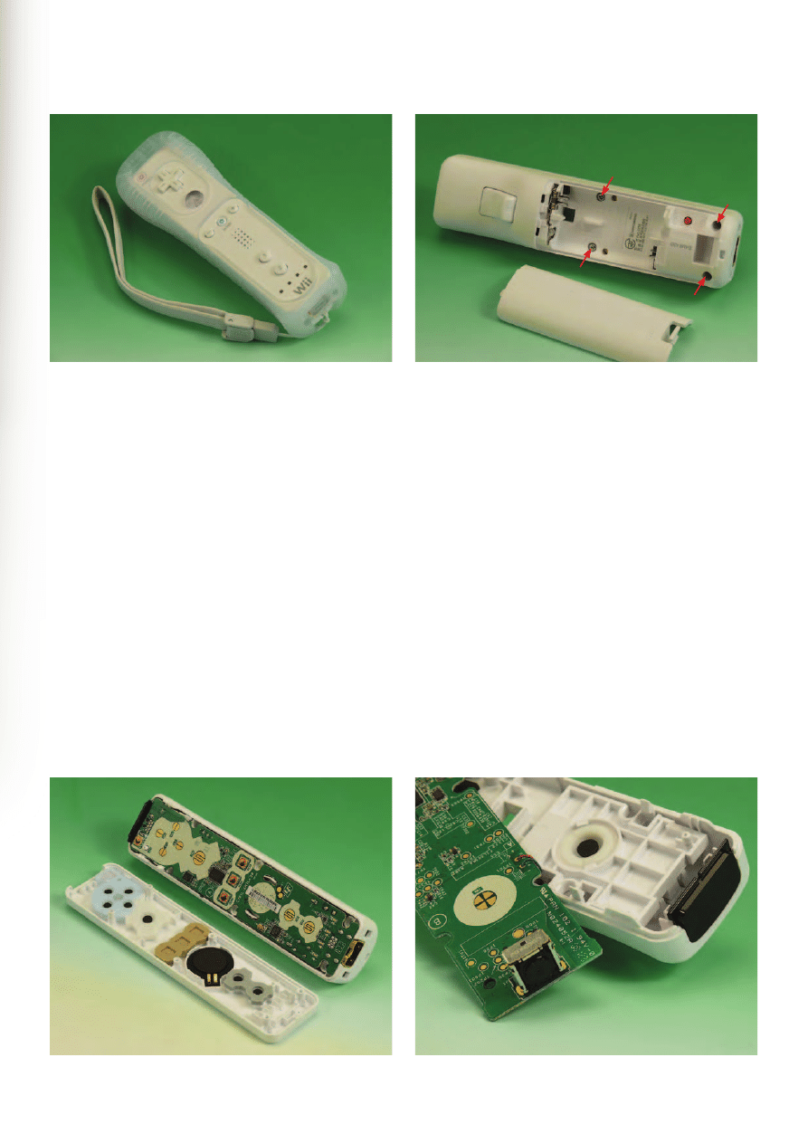
Before you can start properly disman-
tling the unit, you have to expose the
goodies. Start by removing the two tri-
wing screws in the battery compart-
ment (Figure
2). This type of screw
head is sometimes called ‘Y-shaped’,
or you may encounter it under its inter-
national designation: POO-WC45. You
can purchase a suitable screwdriver at
your local home improvement shop, or
you can buy a full set of bits at a dis-
count supermarket. In the Elektor lab,
we discovered that an ordinary cheap
screwdriver with a shaft diameter of
around 2
mm can also do the job if you
file the edges off slightly.
The first two screws are easy to
remove, but the two lower screws,
which are recessed, are more difficult.
Figure 1. The Nintendo Wii remote control unit.
Figure 2. These screws in the battery compartment must be removed.
Figure 3. PCB ahoy!
Figure 4. Camera sensor and IR filter.
PROJECTS
MICROCONTROLLERS
44
elektor - 11/2008
Here it helps to enlarge the holes first
with a drill in order to provide bet-
ter access. You can use a flat-blade
screwdriver to release the two plastic
locks at the upper end of the remote
control, after which the case is open
(Figure
3).
After you tip the board out of the case,
you will see the infrared sensor at the
upper end on the bottom of the board
(Figure
4). The case of the remote con-
trol unit has a filter insert that screens
the sensor against visible light. With
the filter, the maximum sensitiv-
ity lies in the range of approximately
850–920
nm.
With a bit of caution and careful work,
you can unsolder the sensor undamaged.
For this purpose, the authors sawed off
the end of the PCB before unsoldering
the sensor. In the Elektor lab we man-
aged without sawing the board in two,
as you can see from the photos. As the
Wii PCB is assembled using lead-free
solder, you should first apply ‘normal’
must be left in place, as otherwise it
will quickly and permanently turn into
‘dead silicon’.
If you leave the rest of the remote con-
trol board undamaged when removing
the sensor, the remainder of the cir-
cuitry will still function normally. What
you have left over then is an interest-
ing Bluetooth device with an accelera-
tion sensor, for which you can probably
think of some useful applications.
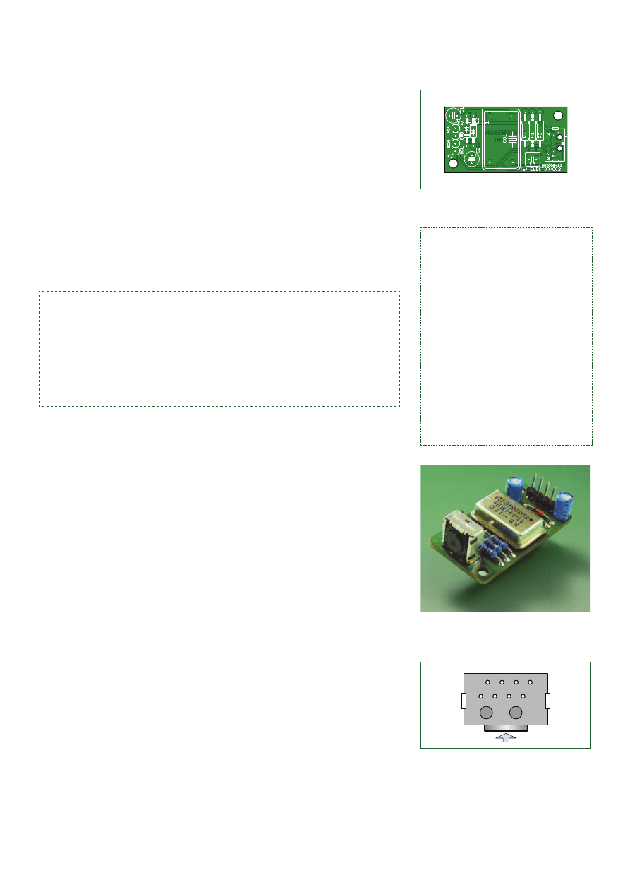
PCB
In order to use the IR camera sensor
with the ATM18 board, you need a bit
of simple circuitry (Figure
8), which
can be built on a small PCB (Figure
9).
A 25-MHz crystal oscillator (CG1) pro-
vides the sensor clock signal (CLK).
The crystal oscillator can be powered
directly from the +5-V supply voltage
of the ATM18 board via PCB connector
K2 (with the voltage decoupled by C1),
but the camera sensor (IR1) requires an
(lead-based) solder to all of the sensor
pins and screen tabs before you start
desoldering. Don’t be too stingy with the
solder, but on the other hand don’t ‘bake’
the solder joints, as otherwise you may
overheat the sensor.
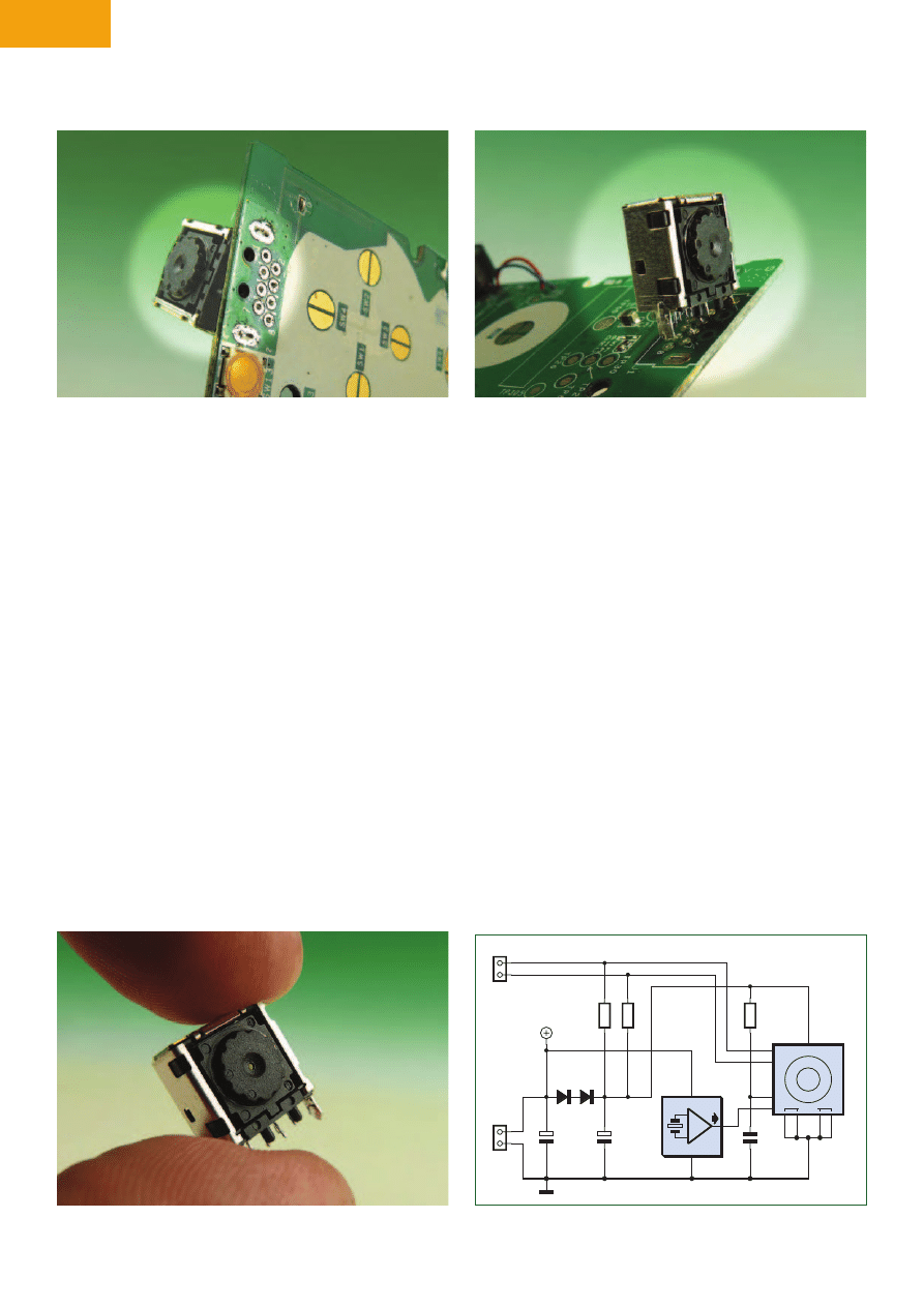
After all the pins have been properly
treated with solder, you can begin des-
oldering. Start by using a solder sucker
or solder braid to remove the solder
from all of the sensor’s solder joints.
The eight signal and power pins can
be freed completely in this way. Now
the sensor is only held in place by
the two solder tabs of its sheet-metal
screen (Figure
5). They can also be
desoldered. While heating the solder
joint, use a screwdriver to cautiously
lever up the sensor on the component
side (Figure
6). Then repeat this proc-
ess with the tab on the other side.
With a few back-and-forth repetitions,
you can quickly pull the sensor free
from the board (Figure
7). The screen
(sheet metal enclosure) of the sensor
Figure 5. Desoldering the pins is not difficult.
Figure 6. The solder tabs of the sheet-metal screen are a bit more stubborn.
Figure 7. The unsoldered camera sensor.
K1
2
1
K2
2
1
R1
2k2
R2
2k2
R3
22k
D1
2x
1N4148
D2
C1
10
M
C2
10
M
16V
16V
IR1
+3V3
SCL
SDA
RES
CLK
GND
Wiimote IR
C3
100n
+5V
080358 - 11
CG1
25MHz
GND
VCC
14
8
7
PC4_SDA
PC5_SCL
I
2
C
Supply
Figure 8. The circuit for connecting the camera sensor.
45
11/2008 - elektor
operating voltage of approximately 3.3
V. This is obtained by wiring two sili-
con diodes in series (D1 and D2, type
1N4148) to reduce the +5-V level on C1
to around 3.3–3.5
V on C2. The obliga-
tory pull-up resistors for the I
2
C bus are
also located on the PCB. Here this bus
operates with 3.3-V signal levels. This is
compatible with the 5-V operating volt-
age of the Mega88 because the active
signal level on the bus lines is obtained
by pulling them to ground, while the
high level is obtained by switching
the output pins to the high-impedance
state. The 3.3-V level is far enough
above the switching threshold voltage
(2.5
V) for reliable data transfer.
The optical sensor from the Wiimote
is a ‘system on chip’ (SOC) device
designed by PixArt as an application-
specific IC for tracking multiple objects
(‘multi-object tracking sensor’) that
includes an integrated signal proc-
essor in addition to the CMOS image
sensor. The signal processor con-
stantly searches for the brightest spots
and determines their coordinates. Up
to four bright objects (‘blobs’) can be
recognised and tracked concurrently.
The sensor is also sensitive to visible
light if the filter is not used, but this
capability is not used here.
Communication
The I
2
C interface makes communica-
tion between the sensor and the micro-
controller relatively easy. The camera
generates an (X,Y) coordinate set for
each blob within its field of view of
1024
r 768 pixels and sends this data
via the interface for further process-
ing. The only question now is how
this works, because Nintendo is totally
silent on this subject. We started by
using a logic analyser to record the
data traffic between the master and
slave devices on the I
2
C bus. After
around two hours, we had a clear
understanding of how the module is
initialised and how to read the data
from it. We identified the signals on
the pins as Ground (two pins), +3.3
V,
SCL, SDA, and three other unknown
signals. Two of them were quickly
identified as the clock input and the
Reset signal. The function of the third
pin remained unclear. Naturally, after
all this research a colleague sent us the
address of the website at http://kako.
com/neta/2007-001/2007-001.html,
which describes the pin assignment
of the sensor (Figure
10). That’s how
it goes – but at least this information
matched our findings. The rest was
just a matter of routine effort. After
we built a prototype, the ATM18-12C
tester (our next project – stay tuned!)
once again proved its worth in the first
functional tests. The slave address of
the Wiimote IR sensors is 0xB0.
Software
The source code of the software in C
(Code Vision AVR) and Basic (Bas-
com AVR) is available on the Elektor
website. The C project
ATM18_Wii_
Remote_IR_Sensor demonstrates the
use of the sensor with the ATM18.
It utilises the internal I
2
C unit of the
Mega88, which means that the pin
assignments are fixed: the data line
(SDA) is on PC4, while the clock line
(SCL) is on PC5. Two additional lines
must be connected for the supply volt-
age. If the LCD module is connected,
it will display the blob coordinates
detected by the sensor.
The ATM18 also outputs the blob posi-
tions in the form of four pairs of values
(X,Y) on the USART interface, with the
format
‘X1,Y1,X2,Y2,X3,Y3,X4,Y4<CRLF>’
This string is output repeatedly. The
value of X can range from 0 to 1023,
while the value of Y can range from
0 to 767. If X = 1023 and Y = 1023,
this means that the associated blob
is not active.
The program ‘Wii-Blob-Track’, which is
also available on the Elektor website,
Figure 9. PCB for using the sensor with the ATM18.
COMPONENTS LIST
Resistors
R1,R2 = 2k
72
R3 = 22k
7
Capacitors
C1,C2 = 10µF 25V
C3 = 100nF
Semiconductors
D1, D2 = 1N4148
CG1 = 25MHz oscillator module
IR1 = Wii Infrared image sensor (see
text)
Miscellaneous
K1, K2 = 2-way SIL header
PCB, order code 080358-1 from Elektor
SHOP. Free artwork download from
www.elektor.com
Figure 10. Lab prototype of the PCB with the camera sensor.
2
4
6
8
1
3
5
7
Figure 11. Sensor pin assignment:
Pin 1 = V
cc
(+3.3 V)
Pins 2 and 3 = GND (ground)
Pin 4 = not used
Pin 5 = SCL (I
2
C)
Pin 6 = SDA (I
2
C)
Pin 7 = CLK (25 MHz)
Pin 8 = Reset
I
2
C
The nature of the I
2
C bus and how to use will be described in future instalments of the
ATM18 series of articles. Here we only want to briefly note that the I
2
C bus is a serial data
transmission bus consisting of two lines: SDA (data) and SCL (clock). Data can be transmit-
ted in both directions: from the microcontroller to the peripheral devices, and from the pe-
ripheral devices to the microcontroller. Several devices can be controlled via the bus. For this
purpose, each I
2
C-device has an address that is sent when a link is established.
PROJECTS
MICROCONTROLLERS
46
elektor - 11/2008
can be run on a PC under Windows to
display the recognised hot spot posi-
tions. This program receives the X,Y
coordinates from the ATM18 board and
plicity of this Wiimote-based solution,
and especially its excellent cost/per-
formance ratio.
You can test the operation of the unit
by wandering around the room with a
lit cigarette lighter in your hand while
someone logs your travels, or you can
fit an IR LED and battery on the back
of your pet cat and observe the move-
ments of your experimental feline sub-
ject in full darkness.
Bascom example
As usual, we also developed a Bascom
application program that provides func-
tions similar to the basic functions of
the C program. We also wrote a specific
property monitoring application for use
with the sample Bascom program.
Unlike the C program, the Bascom pro-
gram does not use the hardware I
2
C
interface, but instead creates an equiv-
alent function in software. This means
that you can use any desired set of pins
for the I
2
C bus. In our case, we use the
same pins as for the C program.
The microcontroller sends several
bytes to the sensor for initialisation.
After this, date is read out at regular
intervals in sets of 16 bytes. Each blob
requires three bytes. As each coordi-
converts them into graphic form. Any-
one who has ever tried to determine
the position of an object from a camera
image can appreciate the clever sim-
LCD 20 x 4
+5V
V
DD
GND
SCL
SDA
080358 - 13
GND
DATA
CLK
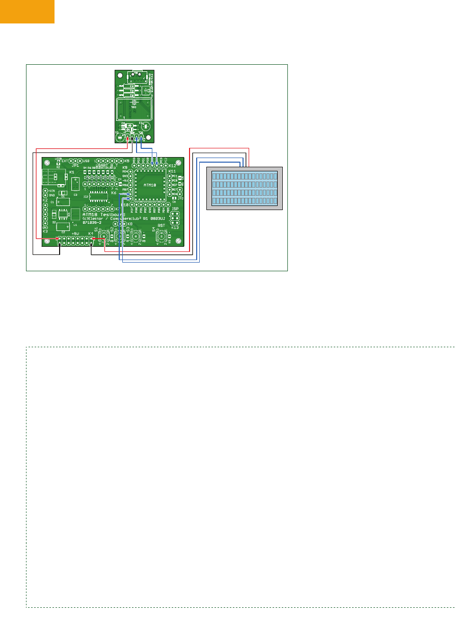
Figure 12. Connecting the sensor and LCD board to the ATM18 board. Here the LCD is connected to PD5 (clock) and PD6 (data).
Listing
Sensor data processing with Bascom
‘ATM18 CCD sensor
‘I2C: SCL = PC5, SDA = PC4
$regfile = “m88def.dat”
$crystal = 16000000
Baud = 38400
Dim Slave As Byte
Dim Slaverd As Byte
Dim D1 As Byte
Dim D2 As Byte
Dim Din(16) As Byte
Dim N As Byte
Dim X1 As Word
Dim Y1 As Word
Dim X2 As Word
Dim Y2 As Word
Dim X3 As Word
Dim Y3 As Word
Dim X4 As Word
Dim Y4 As Word
Dim Xy1 As Integer
Dim Xy2 As Integer
Dim Xy3 As Integer
Declare Sub Send2bytes
Declare Sub Sensorinit
Declare Sub Readsensor
Declare Sub Convertdata
Config Portb = Output
Config Scl = Portc.5
Config Sda = Portc.4
I2cinit
Config I2cdelay = 15
‘I2C sensor address
Slave = &HB0
Slaverd = &HB1
Print “ATM18 I2C_Wii_IR_Sensor”
Sensorinit
Do
Readsensor
Convertdata
Print “P1 “ + Str(x1) + “, “ + Str(y1)
Print “P2 “ + Str(x2) + “, “ + Str(y2)
Print “P3 “ + Str(x3) + “, “ + Str(y3)
Print “P4 “ + Str(x4) + “, “ + Str(y4)
Xy1 = X1 + Y1
Xy1 = Xy1 + X2
Xy1 = Xy1 + Y2
Xy1 = Xy1 + X3
Xy1 = Xy1 + Y3
Xy1 = Xy1 + X4
Xy1 = Xy1 + Y4
Print Xy1
Xy3 = Xy2 - Xy1
Xy2 = Xy1
Xy3 = Abs(xy3)
If Xy3 > 10 Then
Print “**********”
Portb.0 = 1
Else
Portb.0 = 0
End If
47
11/2008 - elektor
nate is a 10-bit value, the eight lower-
order bits of each value are transmit-
ted in one byte, while the two higher-
order bits of the X and Y coordinates
are stuffed into the third byte. After all
the bits have been rearranged prop-
erly, you have four sets of (X,Y) coor-
dinates. They are transmitted via the
serial interface to a terminal emulator
program at a speed of 38,400 baud.
ATM18 I2C_Wii_IR_Sensor
P1 66, 67
P2 813, 228
P3 774, 332
P4 722, 113
The program constantly monitors the
‘bright spots’ to see whether they
change. If they do, an alarm signal is
output on PB0, and it can be used to
drive the ULN2003. This could be con-
nected to a siren, a fire extinguisher, or
some sort of pyrotechnical system. If
you want to protect your art collection,
for instance, all you need is four infra-
red LEDs that are constantly observed
by the sensor. A checksum is formed
from the set of eight coordinates. If it
changes from the value of the previ-
ous measurement by more than 10, an
alarm is generated. This can happen if,
for example, a thief passes through one
of the invisible infrared beams or uses
a fishing rod to drop a line through a
skylight and snag one of your Picassos
that is protected by the IR system.
Now that we’ve laid the groundwork,
we look forward with considerable
anticipation to applications developed
by Elektor readers.
(080358-I)
Internet Links
[1] http://en.wikipedia.org/wiki/Wii_Remote
[2] www.pixart.com.tw
[3] www.analog.com/en/mems-and-sensors/
imems-accelerometers/adxl330/products/
product.html
Waitms 200
Loop
Sub Send2bytes
I2cstart
I2cwbyte Slave
I2cwbyte D1
I2cwbyte D2
I2cstop
End Sub
Sub Sensorinit
D1 = &H30 : D2 = &H01 : Send2bytes : Waitms 10
D1 = &H30 : D2 = &H08 : Send2bytes : Waitms 10
D1 = &H06 : D2 = &H90 : Send2bytes : Waitms 10
D1 = &H08 : D2 = &HC0 : Send2bytes : Waitms 10
D1 = &H1A : D2 = &H40 : Send2bytes : Waitms 10
D1 = &H33 : D2 = &H33 : Send2bytes : Waitms 10
Waitms 100
End Sub
Sub Readsensor
I2cstart
I2cwbyte Slave
D1 = &H36
I2cwbyte D1
I2cstop
Waitms 1
I2cstart
I2cwbyte Slaverd
For N = 1 To 15
I2crbyte Din(n) , Ack
Next N
I2crbyte Din(16) , Nack
I2cstop
Waitms 30
End Sub
Sub Convertdata
X1 = Din(4) And &H30
X1 = X1 * 16
X1 = X1 + Din(2)
Y1 = Din(4) And &HC0
Y1 = Y1 * 4
Y1 = Y1 + Din(3)
X2 = Din(7) And &H30
X2 = X2 * 16
X2 = X2 + Din(5)
Y2 = Din(7) And &HC0
Y2 = Y2 * 4
Y2 = Y2 + Din(6)
X3 = Din(10) And &H30
X3 = X3 * 16
X3 = X3 + Din(8)
Y3 = Din(10) And &HC0
Y3 = Y3 * 4
Y3 = Y3 + Din(9)
X4 = Din(13) And &H30
X4 = X4 * 16
X4 = X4 + Din(11)
Y4 = Din(13) And &HC0
Y4 = Y4 * 4
Y4 = Y4 + Din(12)
End Sub
End
The ATM18 project at
Computer:club
2
ATM18 is a joint project of Elektor and Computer:club
2
(www.cczwei.de) in collaboration
with Udo Jürsz, the editor in chief of www.microdrones.de. The latest developments and
applications of the ATM18 are presented by Computer:club
2
member Wolfgang Rudolph
in the CC
2
-tv programme broadcast on the German NRW-TV channel. The ATM18-AVR
board with the IR camera was described in Instalment 23 of CC
2
-tv, which was broad-
cast on 18 September 2008.
CC
2
-tv is broadcast live by NRW-TV via the cable television network in North Rhine–Westphalia
and as a LiveStream programme via the Internet (www.nrw.tv/home/cc2). CC
2
-tv
is also
available as a podcast from www.cczwei.de and – a few days later – from sevenload.de.
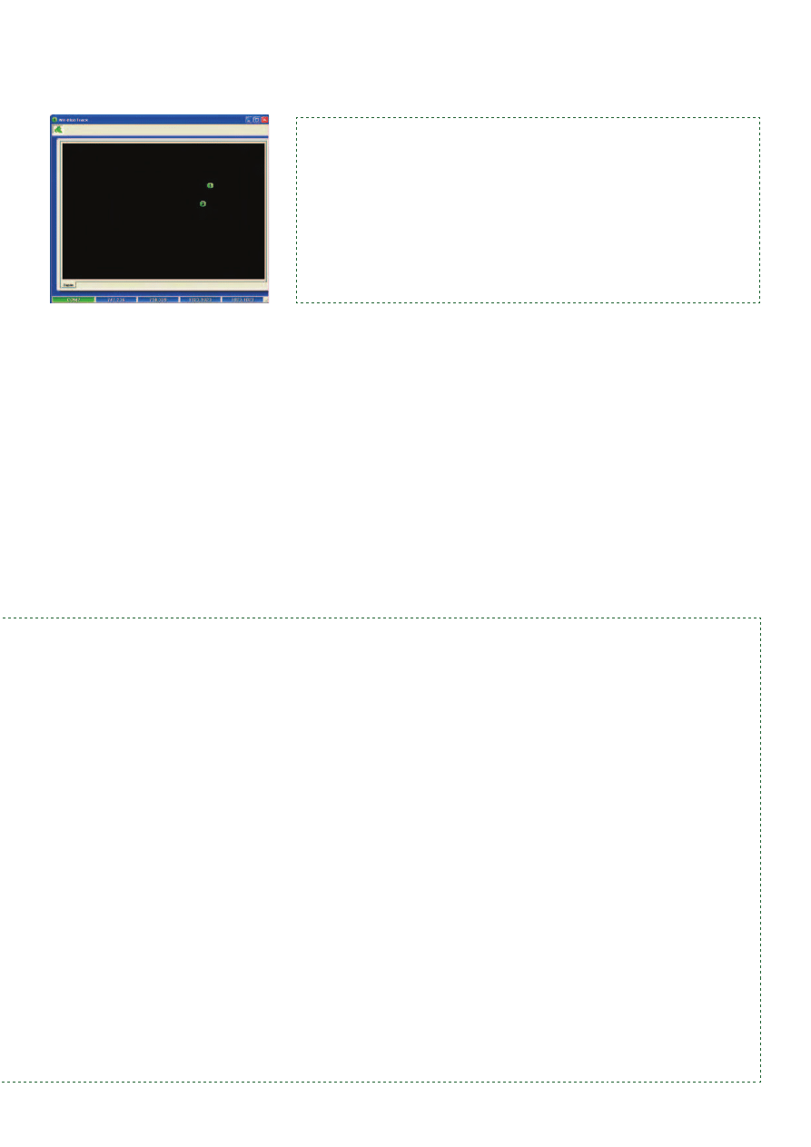
Figure 13. Coordinate processing by the PC program. Up to
four ‘blobs’ can be shown concurrently.
Wyszukiwarka
Podobne podstrony:
red hot chilli peppers
12 151 159 Practical Tests of Coated Hot Forging Dies
ATM18 Relay Board
Magiczne przygody kubusia puchatka 22 THE WOMEN ARE HOT!
Tracking in school prezentacja
Aarts Efficient Tracking of the Cross Correlation Coefficient
Hot Bike October 2009
46 643 656 Vacuum HT of Hot Work Steel
Electric Hot Water
Test kompetencji po I sem. kl. IV - Winners 1, HOT SPOB 2 TESTY
Jarzębowski ŻSustainable hot spot analysis
Hot Chocolate Almond
Avril Lavigne Hot
hot proposal
Spiked Hot Chocolate
Project Progress and Revenue Tracking
Microwave Hot Cocoa
51 721 736 Evaluation of the Cyclic Behaviour During High Temperature Fatique of Hot Works
Sprawdzian hot, Szkoła, Testy,sprawdziany
więcej podobnych podstron