
Understanding IP Addressing:
Everything You Ever Wanted To Know
CIDR
Subnetting
VLSM
Class A
Class B
Class C
All-0s
All-1s
Classful
Classless
Longest Match
Extended-Network Prefix
Prefix -Length
Supernetting
Mask
Network-Prefix
Host-Number
/16
/24
/8
Chuck Semeria
NSD Marketing
3Com Corporation
April 26, 1996

Introduction
In the mid-1990's, the Internet is a dramatically different network than when it was first
established in the early 1980's. Today, the Internet has entered the public consciousness
as the world's largest public data network, doubling in size every nine months. This is
reflected in the tremendous popularity of the World Wide Web (WWW), the
opportunities that businesses see in reaching customers from virtual storefronts, and the
emergence of new types and methods of doing business. It is clear that expanding
business and social awareness will continue to increase public demand for access to
resources on the Internet.
There is a direct relationship between the value of the Internet and the number of sites
connected to the Internet. As the Internet grows, the value of each site's connection to
the Internet increases because it provides the organization with access to an ever
expanding user/customer population.
Internet Scaling Problems
Over the past few years, the Internet has experienced two major scaling issues as it has
struggled to provide continuous and uninterrupted growth:
-
The eventual exhaustion of the IPv4 address space
-
The ability to route traffic between the ever increasing number of networks that
comprise the Internet
The first problem is concerned with the eventual depletion of the IP address space. The
current version of IP, IP version 4 (IPv4), defines a 32-bit address which means that
there are only 2
32
(4,294,967,296) IPv4 addresses available. This might seem like a
large number of addresses, but as new markets open and a significant portion of the
world's population becomes candidates for IP addresses, the finite number of IP
addresses will eventually be exhausted.
The address shortage problem is aggravated by the fact that portions of the IP address
space have not been efficiently allocated. Also, the traditional model of classful
addressing does not allow the address space to be used to its maximum potential. The
Address Lifetime Expectancy (ALE) Working Group of the IETF has expressed
concerns that if the current address allocation policies are not modified, the Internet will
experience a near to medium term exhaustion of its unallocated address pool. If the
Internet's address supply problem is not solved, new users may be unable to connect to
the global Internet!
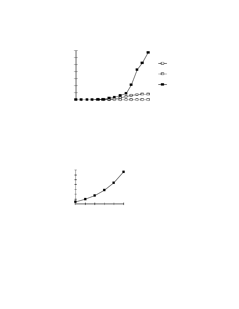
Networks (in thousands)
Class A
Class B
0
10
20
30
40
50
60
70
1983
1985
1987
1989
1991
1993
1995
Class C
Figure 1: Assigned and Allocated Network Numbers
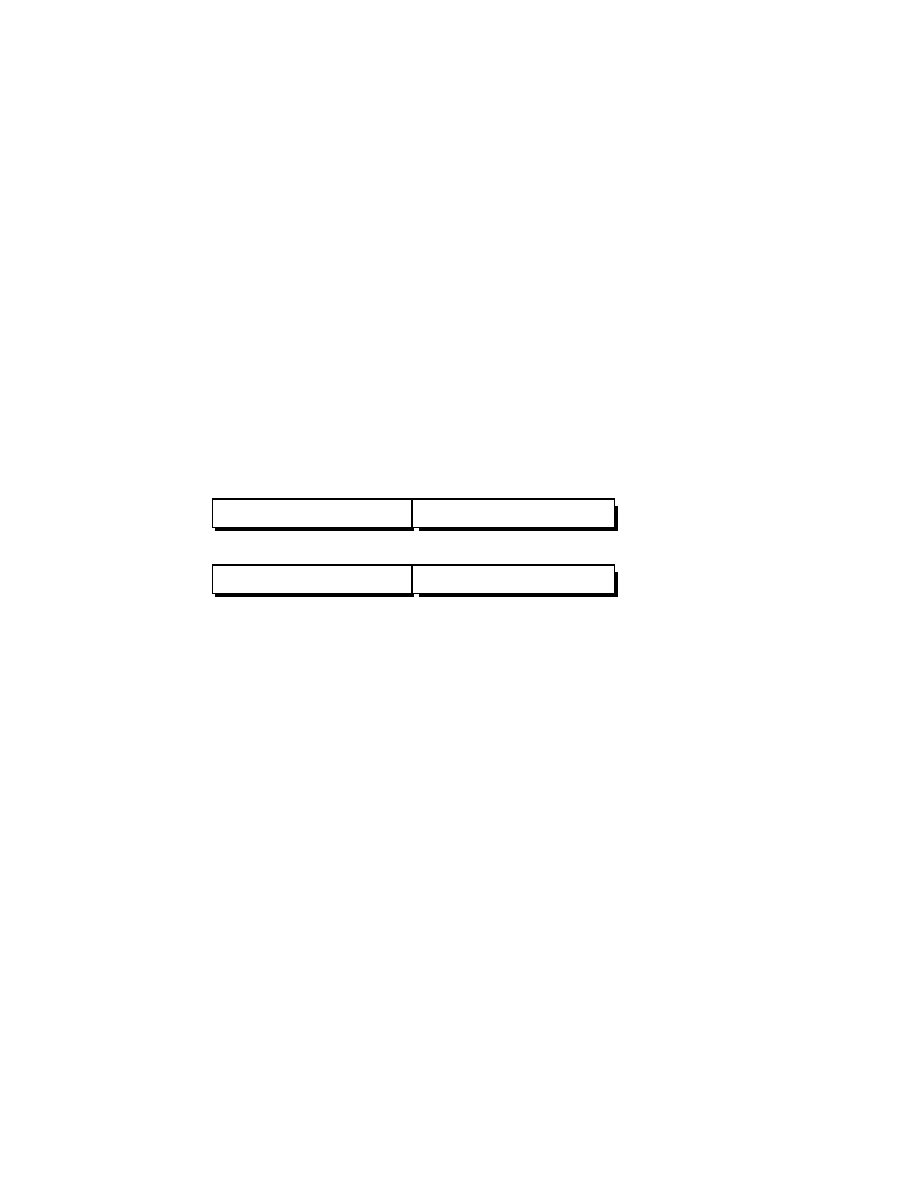
The second problem is caused by the rapid growth in the size of the Internet routing
tables. Internet backbone routers are required to maintain complete routing information
for the Internet. Over recent years, routing tables have experienced exponential growth
as increasing numbers of organizations connect to the Internet - in December 1990 there
were 2,190 routes, in December 1992 there were 8,500 routes, and in December 1995
there were 30,000+ routes.
0
5
10
15
20
25
30
35
1990
1991
1992
1993
1994
1995
Routing Table Entries
(in thousands)
Figure 2: Growth of Internet Routing Tables
Unfortunately, the routing problem cannot be solved by simply installing more router
memory and increasing the size of the routing tables. Other factors related to the
capacity problem include the growing demand for CPU horsepower to compute routing
table/topology changes, the increasingly dynamic nature of WWW connections and their
effect on router forwarding caches, and the sheer volume of information that needs to be
managed by people and machines. If the number of entries in the global routing table is
allowed to increase without bounds, core routers will be forced to drop routes and
portions of the Internet will become unreachable!
The long term solution to these problems can be found in the widespread deployment of
IP Next Generation (IPng or IPv6) towards the turn of the century. However, while the
Internet community waits for IPng, IPv4 will need to be patched and modified so that
the Internet can continue to provide the universal connectivity we have come to expect.
This patching process may cause a tremendous amount of pain and may alter some of
our fundamental concepts about the Internet.
Classful IP Addressing
When IP was first standardized in September 1981, the specification required that each
system attached to an IP-based internet be assigned a unique, 32-bit Internet address
value. Some systems, such as routers which have interfaces to more than one network,
must be assigned a unique IP address for each network interface.
The first part of an Internet address identifies the network on which the host resides,
while the second part identifies the particular host on the given network. This created the
two-level addressing hierarchy which is illustrated in Figure 3.
Network-Prefix
Host-Number
Network-Number
Host-Number
or
Figure 3: Two-Level Internet Address Structure
In recent years, the network-number field has been referred to as the "network-prefix"
because the leading portion of each IP address identifies the network number. All hosts
on a given network share the same network-prefix but must have a unique host-number.
Similarly, any two hosts on different networks must have different network-prefixes but
may have the same host-number.
Primary Address Classes
In order to provide the flexibility required to support different size networks, the
designers decided that the IP address space should be divided into three different address
classes - Class A, Class B, and Class C. This is often referred to as "classful"
addressing because the address space is split into three predefined classes, groupings, or
categories. Each class fixes the boundary between the network-prefix and the host-
number at a different point within the 32-bit address. The formats of the fundamental
address classes are illustrated in Figure 4.
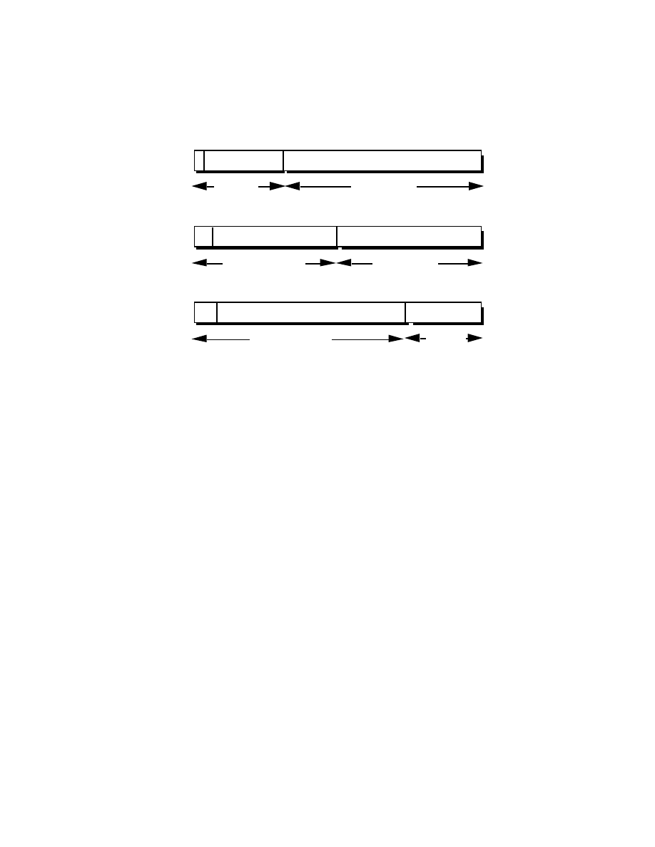
Class A
Class B
Class C
0
7 8
31
0 1
Host-Number
10
15 16
31
0 2
110
23 24
31
0
3
Network-
Number
Network-Number
Network-Number
Host-Number
Host-
Number
bit #
bit #
bit #
Figure 4: Principle Classful IP Address Formats
One of the fundamental features of classful IP addressing is that each address contains a
self-encoding key that identifies the dividing point between the network-prefix and the
host-number. For example, if the first two bits of an IP address are 1-0, the dividing
point falls between the 15th and 16th bits. This simplified the routing system during the
early years of the Internet because the original routing protocols did not supply a
"deciphering key" or "mask" with each route to identify the length of the network-prefix.
Class A Networks (/8 Prefixes)
Each Class A network address has an 8-bit network-prefix with the highest order bit set
to 0 and a seven-bit network number, followed by a 24-bit host-number. Today, it is no
longer considered 'modern' to refer to a Class A network. Class A networks are now
referred to as "/8s" (pronounced "slash eight" or just "eights") since they have an 8-bit
network-prefix.
A maximum of 126 (2
7
-2) /8 networks can be defined. The calculation requires that the
2 is subtracted because the /8 network 0.0.0.0 is reserved for use as the default route and
the /8 network 127.0.0.0 (also written 127/8 or 127.0.0.0/8) has been reserved for the
"loopback" function. Each /8 supports a maximum of 16,777,214 (2
24
-2) hosts per
network. The host calculation requires that 2 is subtracted because the all-0s ("this
network") and all-1s ("broadcast") host-numbers may not be assigned to individual
hosts.
Since the /8 address block contains 2
31
(2,147,483,648 ) individual addresses and the
IPv4 address space contains a maximum of 2
32
(4,294,967,296) addresses, the /8
address space is 50% of the total IPv4 unicast address space.
Class B Networks (/16 Prefixes)
Each Class B network address has a 16-bit network-prefix with the two highest order
bits set to 1-0 and a 14-bit network number, followed by a 16-bit host-number. Class B
networks are now referred to as"/16s" since they have a 16-bit network-prefix.
A maximum of 16,384 (2
14
) /16 networks can be defined with up to 65,534 (2
16
-2)
hosts per network. Since the entire /16 address block contains 2
30
(1,073,741,824)
addresses, it represents 25% of the total IPv4 unicast address space.
Class C Networks (/24 Prefixes)
Each Class C network address has a 24-bit network-prefix with the three highest order
bits set to 1-1-0 and a 21-bit network number, followed by an 8-bit host-number. Class
C networks are now referred to as "/24s" since they have a 24-bit network-prefix.
A maximum of 2,097,152 (2
21
) /24 networks can be defined with up to 254 (2
8
-2)
hosts per network. Since the entire /24 address block contains 2
29
(536,870,912)
addresses, it represents 12.5% (or 1/8th) of the total IPv4 unicast address space.
Other Classes
In addition to the three most popular classes, there are two additional classes. Class D
addresses have their leading four-bits set to 1-1-1-0 and are used to support IP
Multicasting. Class E addresses have their leading four-bits set to 1-1-1-1 and are
reserved for experimental use.
Dotted-Decimal Notation
To make Internet addresses easier for human users to read and write, IP addresses are
often expressed as four decimal numbers, each separated by a dot. This format is called
"dotted-decimal notation."
Dotted-decimal notation divides the 32-bit Internet address into four 8-bit (byte) fields
and specifies the value of each field independently as a decimal number with the fields
separated by dots. Figure 5 shows how a typical /16 (Class B) Internet address can be
expressed in dotted decimal notation.
10 010001
00001010
00100010
00000011
.
.
.
145.10.34.3
145
10
34
3
0
31
bit #
Figure 5: Dotted-Decimal Notation
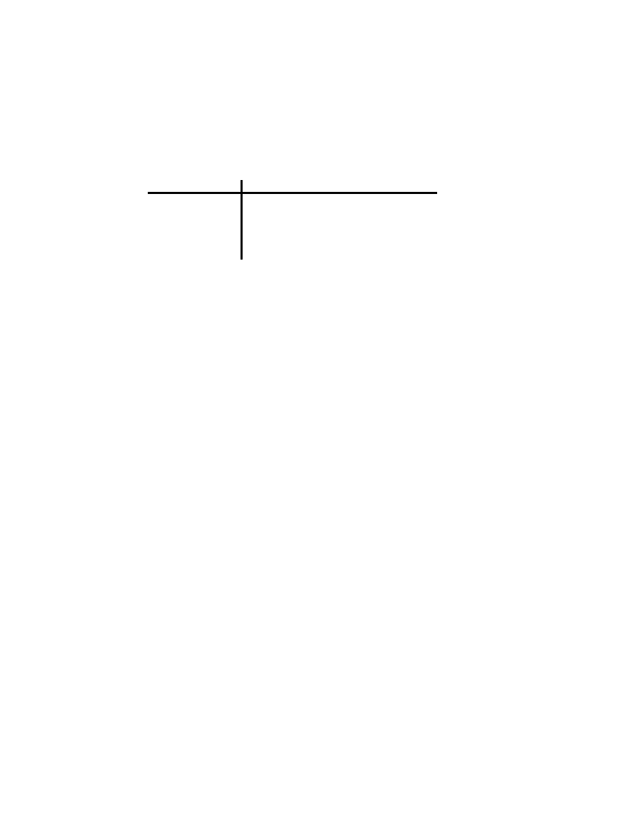
Table 1 displays the range of dotted-decimal values that can be assigned to each of the
three principle address classes. The "xxx" represents the host-number field of the
address which is assigned by the local network administrator.
Table 1: Dotted-Decimal Ranges for Each Address Class
A (/8 prefixes)
B (/16 prefixes)
C (/24 prefixes)
1.xxx.xxx.xxx through 126.xxx.xxx.xxx
128.0.xxx.xxx through 191.255.xxx.xxx
Address Class
Dotted-Decimal Notation Ranges
192.0.0.xxx through 223.255.255.xxx
Unforeseen Limitations to Classful Addressing
The original designers never envisioned that the Internet would grow into what it has
become today. Many of the problems that the Internet is facing today can be traced back
to the early decisions that were made during its formative years.
-
During the early days of the Internet, the seemingly unlimited address space allowed
IP addresses to be allocated to an organization based on its request rather than its
actual need. As a result, addresses were freely assigned to those who asked for
them without concerns about the eventual depletion of the IP address space.
-
The decision to standardize on a 32-bit address space meant that there were only 2
32
(4,294,967,296) IPv4 addresses available. A decision to support a slightly larger
address space would have exponentially increased the number of addresses thus
eliminating the current address shortage problem.
-
The classful A, B, and C octet boundaries were easy to understand and implement,
but they did not foster the efficient allocation of a finite address space. Problems
resulted from the lack of a network class that was designed to support medium-
sized organizations. A /24, which supports 254 hosts, is too small while a /16,
which supports 65,534 hosts, is too large. In the past, the Internet has assigned sites
with several hundred hosts a single /16 address instead of a couple of /24s
addresses. Unfortunately, this has resulted in a premature depletion of the /16
network address space. The only readily available addresses for medium-size
organizations are /24s which have the potentially negative impact of increasing the
size of the global Internet's routing table.
The subsequent history of Internet addressing is focused on a series of steps that
overcome these addressing issues and have supported the growth of the global Internet.
Additional Practice with Classful Addressing
Please turn to Appendix B for practical exercises to further your understanding of
Classful IP Addressing.
Subnetting
In 1985, RFC 950 defined a standard procedure to support the subnetting, or division, of
a single Class A, B, or C network number into smaller pieces. Subnetting was
introduced to overcome some of the problems that parts of the Internet were beginning
to experience with the classful two-level addressing hierarchy:
-
Internet routing tables were beginning to grow.
-
Local administrators had to request another network number from the Internet
before a new network could be installed at their site.
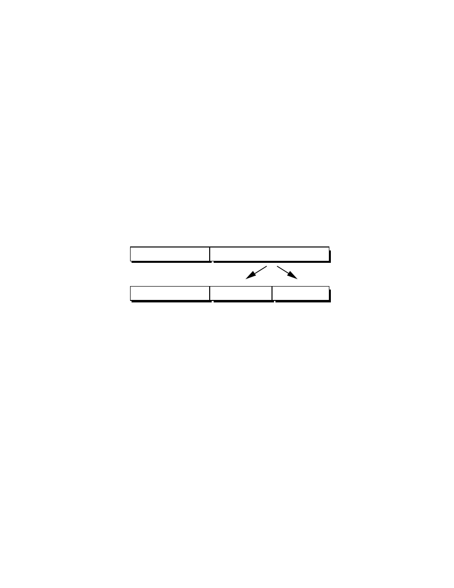
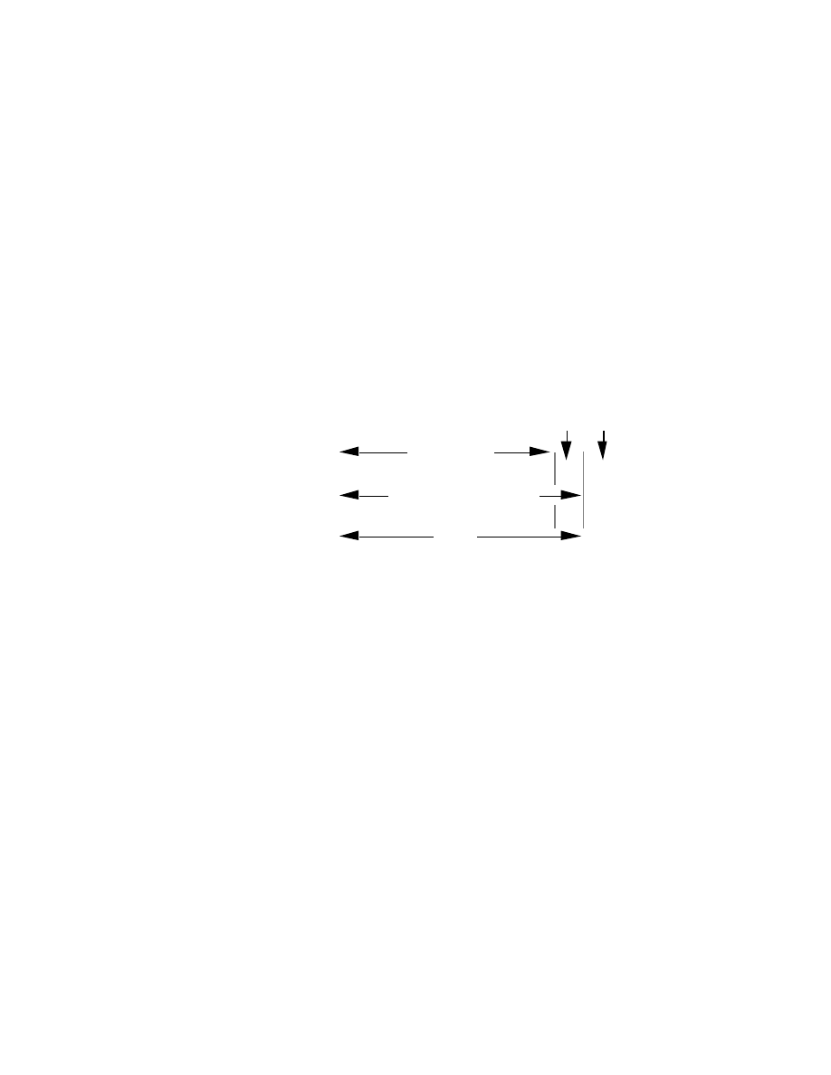
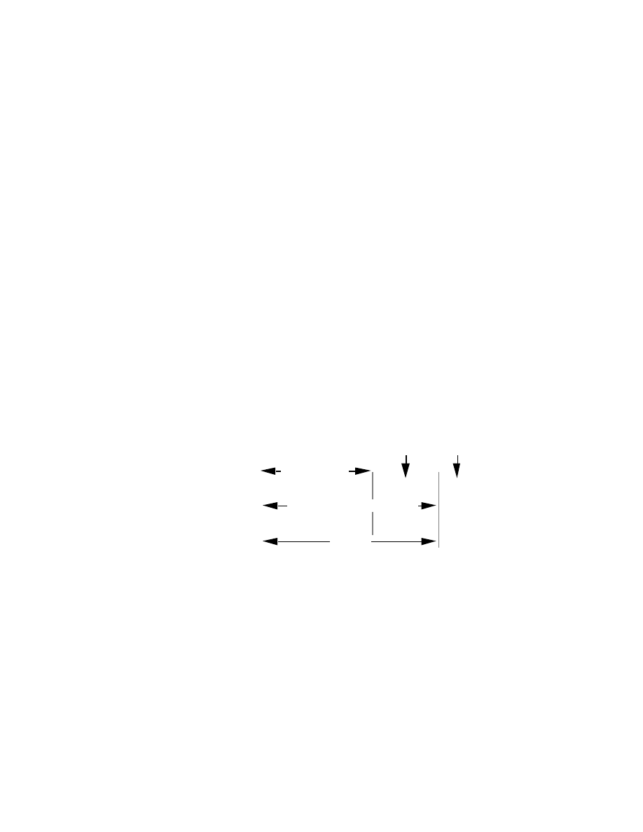
Both of these problems were attacked by adding another level of hierarchy to the IP
addressing structure. Instead of the classful two-level hierarchy, subnetting supports a
three-level hierarchy. Figure 6 illustrates the basic idea of subnetting which is to divide
the standard classful host-number field into two parts - the subnet-number and the host-
number on that subnet.
Network-Prefix
Host-Number
Network-Prefix
Host-Number
Subnet-Number
Two-Level Classful Hierarchy
Three-Level Subnet Hierarchy
Figure 6: Subnet Address Hierarchy
Subnetting attacked the expanding routing table problem by ensuring that the subnet
structure of a network is never visible outside of the organization's private network. The
route from the Internet to any subnet of a given IP address is the same, no matter which
subnet the destination host is on. This is because all subnets of a given network number
use the same network-prefix but different subnet numbers. The routers within the
private organization need to differentiate between the individual subnets, but as far as the
Internet routers are concerned, all of the subnets in the organization are collected into a
single routing table entry. This allows the local administrator to introduce arbitrary
complexity into the private network without affecting the size of the Internet's routing
tables.
Subnetting overcame the registered number issue by assigning each organization one (or
at most a few) network number(s) from the IPv4 address space. The organization was
then free to assign a distinct subnetwork number for each of its internal networks. This
allows the organization to deploy additional subnets without needing to obtain a new
network number from the Internet.
Internet
130.5.0.0
Private Network
130.5.32.0
130.5.64.0
130.5.96.0
130.5.128.0
130.5.160.0
130.5.192.0
130.5.224.0
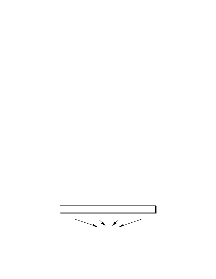
Figure 7: Subnetting Reduces the Routing Requirements of the Internet
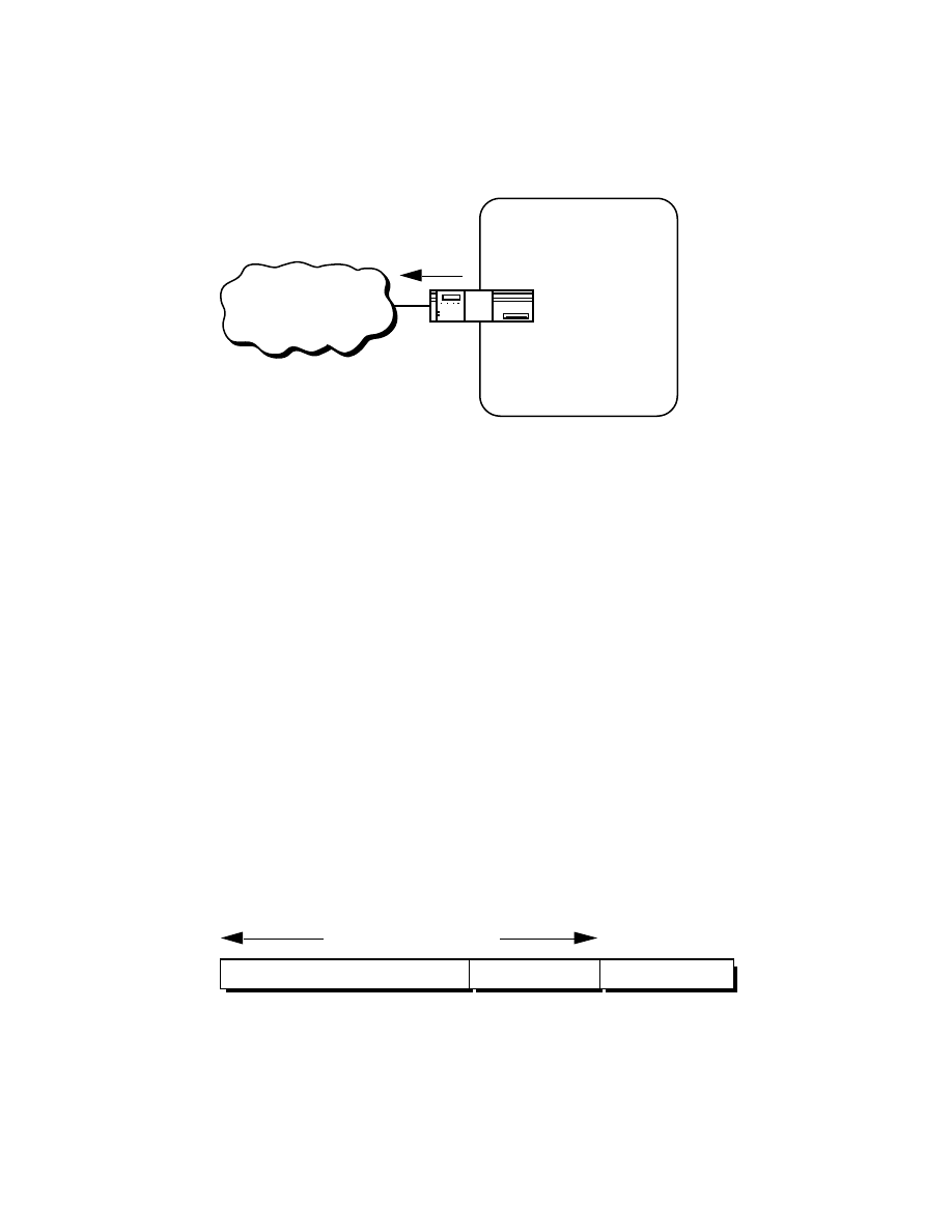
In Figure 7, a site with several logical networks uses subnet addressing to cover them
with a single /16 (Class B) network address. The router accepts all traffic from the
Internet addressed to network 130.5.0.0, and forwards traffic to the interior subnetworks
based on the third octet of the classful address. The deployment of subnetting within the
private network provides several benefits:
-
The size of the global Internet routing table does not grow because the site
administrator does not need to obtain additional address space and the routing
advertisements for all of the subnets are combined into a single routing table entry.
-
The local administrator has the flexibility to deploy additional subnets without
obtaining a new network number from the Internet.
-
Route flapping (i.e., the rapid changing of routes) within the private network does
not affect the Internet routing table since Internet routers do not know about the
reachability of the individual subnets - they just know about the reachability of the
parent network number.
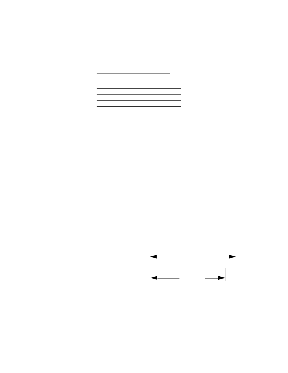
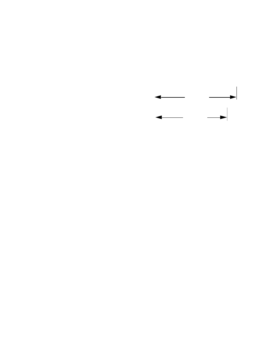
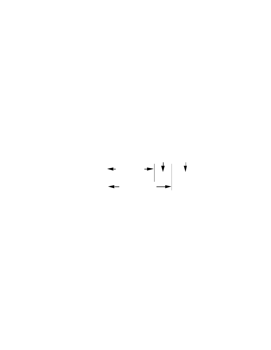
Extended-Network-Prefix
Internet routers use only the network-prefix of the destination address to route traffic to a
subnetted environment. Routers within the subnetted environment use the extended-
network-prefix to route traffic between the individual subnets. The extended-network-
prefix is composed of the classful network-prefix and the subnet-number.
Network-Prefix
Host-Number
Subnet-Number
Extended-Network-Prefix
Figure 8: Extended-Network-Prefix
The extended-network-prefix has traditionally been identified by the subnet mask. For
example, if you have the /16 address of 130.5.0.0 and you want to use the entire third
octet to represent the subnet-number, you need to specify a subnet mask of
255.255.255.0. The bits in the subnet mask and the Internet address have a one-to-one
correspondence. The bits of the subnet mask are set to 1 if the system examining the
address should treat the corresponding bit in the IP address as part of the extended-
network-prefix. The bits in the mask are set to 0 if the system should treat the bit as part
of the host-number. This is illustrated if Figure 9.
IP Address: 130.5.5.25 10000010.00000101.00000101.00011001
Subnet Mask: 255.255.255.0 11111111.11111111.11111111.00000000
subnet-
number
host-
number
extended-network-
prefix
network-prefix
Figure 9: Subnet Mask
The standards describing modern routing protocols often refer to the extended-network-
prefix-length rather than the subnet mask. The prefix length is equal to the number of
contiguous one-bits in the traditional subnet mask. This means that specifying the
network address 130.5.5.25 with a subnet mask of 255.255.255.0 can also be expressed
as 130.5.5.25/24. The /<prefix-length> notation is more compact and easier to
understand than writing out the mask in its traditional dotted-decimal format. This is
illustrated in Figure 10.
130.5.5.25 10000010.00000101.00000101.00011001
255.255.255.0 11111111.11111111.11111111.00000000
24-bit extended-
network-prefix
130.5.5.25/24 10000010.00000101.00000101.00011001
or
Figure 10: Extended-Network-Prefix Length
However, it is important to note that modern routing protocols still carry the subnet
mask. There are no Internet standard routing protocols that have a one-byte field in their
header that contains the number of bits in the extended-network prefix. Rather, each
routing protocol is still required to carry the complete four-octet subnet mask.

Subnet Design Considerations
The deployment of an addressing plan requires careful thought on the part of the
network administrator. There are four key questions that must be answered before any
design should be undertaken:
1) How many total subnets does the organization need today?
2) How many total subnets will the organization need in the future?
3) How many hosts are there on the organization's largest subnet today?
4) How many hosts will there be on the organization's largest subnet in the future?
The first step in the planning process is to take the maximum number of subnets
required and round up to the nearest power of two. For example, if a organization needs
9 subnets, 2
3
(or 8) will not provide enough subnet addressing space, so the network
administrator will need to round up to 2
4
(or 16). When performing this assessment, it
is critical that the network administrator always allow adequate room for future growth.
For example, if 14 subnets are required today, then 16 subnets might not be enough in
two years when the 17th subnet needs to be deployed. In this case, it might be wise to
allow for more growth and select 2
5
(or 32) as the maximum number of subnets.
The second step is to make sure that there are enough host addresses for the
organization's largest subnet. If the largest subnet needs to support 50 host addresses
today, 2
5
(or 32) will not provide enough host address space so the network
administrator will need to round up to 2
6
(or 64).
The final step is to make sure that the organization's address allocation provides enough
bits to deploy the required subnet addressing plan. For example, if the organization has
a single /16, it could easily deploy 4-bits for the subnet-number and 6-bits for the host
number. However, if the organization has several /24s and it needs to deploy 9 subnets,
it may be required to subnet each of its /24s into four subnets (using 2 bits) and then
build the internet by combining the subnets of 3 different /24 network numbers. An
alternative solution, would be to deploy network numbers from the private address
space (RFC 1918) for internal connectivity and use a Network Address Translator
(NAT) to provide external Internet access.
Subnet Example #1
Given
An organization has been assigned the network number 193.1.1.0/24 and it needs to
define six subnets. The largest subnet is required to support 25 hosts.
Defining the Subnet Mask / Extended-Prefix Length
The first step is to determine the number of bits required to define the six subnets. Since
a network address can only be subnetted along binary boundaries, subnets must be
created in blocks of powers of two [ 2 (2
1
), 4 (2
2
), 8 (2
3
), 16 (2
4
), etc. ]. Thus, it is
impossible to define an IP address block such that it contains exactly six subnets. For
this example, the network administrator must define a block of 8 (2
3
) and have two
unused subnets that can be reserved for future growth.
Since 8 = 2
3
, three bits are required to enumerate the eight subnets in the block. In this
example, the organization is subnetting a /24 so it will need three more bits, or a /27, as
the extended-network-prefix. A 27-bit extended-network-prefix can be expressed in
dotted-decimal notation as 255.255.255.224. This is illustrated in Figure 11.
193.1.1.0/24 = 11000001.00000001.00000001.00000000
network-prefix
extended-network-prefix
255.255.255.224 = 11111111.11111111.11111111.11100000
subnet-
number
bits
host-
number
bits
27-bits
Figure 11: Example #1 - Defining the Subnet Mask/Extended-Prefix Length
A 27-bit extended-network-prefix leaves 5 bits to define host addresses on each subnet.
This means that each subnetwork with a 27-bit prefix represents a contiguous block of
2
5
(32) individual IP addresses. However, since the all-0s and all-1s host addresses
cannot be allocated, there are 30 (2
5
-2) assignable host addresses on each subnet.
Defining Each of the Subnet Numbers
The eight subnets will be numbered 0 through 7. Throughout the remainder of this
paper, the XXX
2
notation indicates the binary representation of the number. The 3-bit
binary representation of the decimal values 0 through 7 are: 0 (000
2
), 1 (001
2
), 2 (010
2
),
3 (011
2
), 4 (100
2
), 5 (101
2
), 6 (110
2
), and 7 (111
2
).
In general, to define Subnet #n, the network administrator places the binary
representation of n into the bits of the subnet-number field. For example, to define
Subnet #6, the network administrator simply places the binary representation of 6 (110
2
)
into the 3-bits of the subnet-number field.
The eight subnet numbers for this example are given below. The underlined portion of
each address identifies the extended-network-prefix, while the bold digits identify the 3-
bits representing the subnet-number field:
Base Net:
11000001.00000001.00000001
.00000000 = 193.1.1.0/24
Subnet #0:
11000001.00000001.00000001.
000
00000 = 193.1.1.0/27
Subnet #1:
11000001.00000001.00000001.
001
00000 = 193.1.1.32/27
Subnet #2:
11000001.00000001.00000001.
010
00000 = 193.1.1.64/27
Subnet #3:
11000001.00000001.00000001.
011
00000 = 193.1.1.96/27
Subnet #4:
11000001.00000001.00000001.
100
00000 = 193.1.1.128/27
Subnet #5:
11000001.00000001.00000001.
101
00000 = 193.1.1.160/27
Subnet #6:
11000001.00000001.00000001.
110
00000 = 193.1.1.192/27
Subnet #7:
11000001.00000001.00000001.
111
00000 = 193.1.1.224/27
An easy way to check if the subnets are correct is to ensure that they are all multiples of
the Subnet #1 address. In this case, all subnets are multiples of 32: 0, 32, 64, 96, ...
The All-0s Subnet and The All-1s Subnet
When subnetting was first defined in RFC 950, it prohibited the use of the all-0s and the
all-1s subnet. The reason for this restriction was to eliminate situations that could
potentially confuse a classful router. Note that today a router can be both classless and
classful at the same time - it could be running RIP-1 (a classful protocol) and BGP-4 (a
classless protocol) at the same time.
With respect to the all-0s subnet, a router requires that each routing table update include
the route/<prefix-length> pair to differentiate between a route to the all-0s subnet and a
route to the entire network. For example, when using RIP-1 which does not supply a
mask or prefix-length with each route, the routing advertisements for subnet
193.1.1.0/27 and for network 193.1.1.0/24 are identical - 193.1.1.0. Without somehow
knowing the prefix-length or mask, a router cannot tell the difference between a route to
the all-0s subnet and the route to the entire network! This is illustrated in Figure 12.
Network Route: 193.1.1.0/24 11000001.00000001.00000001.00000000
Subnet Route: 193.1.1.0/27 11000001.00000001.00000001.00000000
24-bit prefix
27-bit prefix
Figure 12: Differentiating Between a Route to the All-0s Subnet and the Entire Network
Regarding the all-1s subnet, a router requires that each routing table entry include the
prefix-length so that it can determine if a broadcast (directed or all-subnets) should be
sent only to the all-1s subnet or to the entire network. For example, when the routing
table does not contain a mask or prefix-length for each route, confusion can occur
because the same broadcast address (193.1.1.255) is used for both for the entire network
193.1.1.0/24 and the all-1s subnet 193.1.1.224/27. This is illustrated in Figure 13.
Broadcast to Network:193.1.1.0/24 11000001.00000001.00000001.11111111
Broadcast to Subnet: 193.1.1.224/27 11000001.00000001.00000001.11111111
24-bit prefix
27-bit prefix
Figure 13: Identifying a Broadcast to the All-1s Subnet and the Entire Network
Note that by default, NETBuilder software permits the forwarding of traffic to a directed
broadcast address but does not forward traffic to the all-subnets broadcast address. The
network administrator can modify this behavior via the -IP CONTrol parameter
switches FwdSubnetBcast | NoFwdSubnetBcast and FwdAllSubnetBcast |
NoFwdAllSubnetBcast.
With the development of routing protocols that supply the mask or prefix-length with
each route, the address space defined by the all-0s and all-1s subnets is once again
usable despite the cautions in RFC 950. As a result, vendors have begun to
accommodate user demand and permit the configuration of the all-0s and all-1s subnets
on router interfaces. There are three factors that determine when these subnets can be
used with NETBuilder software.
-
The interior gateway protocol (IGP)
-
The version number of the NETBuilder software release
-
The capabilities of other routers in the organization's network.
To support the deployment of the all-0s and all-1s subnets, the IGP must either carry
extended-network-prefixes or have a mechanism to map each route to its extended-
network-prefix. Both OSPF and I-IS-IS carry extended-network-prefixes, so they
support the deployment of the all-0s and all-1s subnets in arbitrarily complex topologies.
RIP-1 does not carry extended-network-prefixes but the RcvSubnetMask parameter
along with the -RIPIP CONTrol (..[Aggregate| NoAggregate], [DeAggregate|
NoDeAggregate]) switches support the deployment of the all-0s and all-1s subnets in
simple topologies.
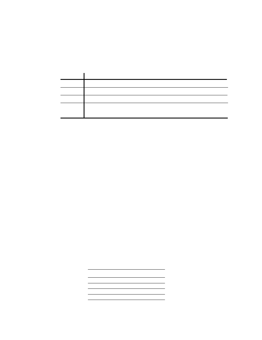
NETBuilder software has taken a phased approach in its support for the deployment of
the all-0s and all-1s subnets. Table 2 shows the NETBuilder software version number
that first implemented the various features that support the deployment of these subnets.
Table 2: NETBuilder Software Features Supporting the All-0s and All-1s Subnets
Release
Feature Supported
6.2
7.0.0.6
7.1
8.3.0.2
Permits a router interface to be configured with all-0s in the subnet field
Permits a router interface to be configured with all-1s in the subnet field
Correctly learns and forwards to routes with all-0s in the subnet field
Correctly learns and forwards to routes with all-1s in the subnet field
7.2.1
Finally, the other routers in the organization's network need to be able to correctly
interpret, learn, and forward traffic to other subnetworks with all-0s and all-1s in their
subnet number field.
Defining Host Addresses for Each Subnet
According to Internet practices, the host-number field of an IP address cannot contain all
0-bits or all 1-bits. The all-0s host-number identifies the base network (or subnetwork)
number, while the all-1s host-number represents the broadcast address for the network
(or subnetwork).
In our current example, there are 5 bits in the host-number field of each subnet address.
This means that each subnet represents a block of 30 host addresses (2
5
-2 = 30, note
that the 2 is subtracted because the all-0s and the all-1s host addresses cannot be used).
The hosts on each subnet are numbered 1 through 30.
In general, to define the address assigned to Host #n of a particular subnet, the network
administrator places the binary representation of n into the subnet's host-number field.
For example, to define the address assigned to Host #15 on Subnet #2, the network
administrator simply places the binary representation of 15 (01111
2
) into the 5-bits of
Subnet #2's host-number field.
The valid host addresses for Subnet #2 in our example are given below. The underlined
portion of each address identifies the extended-network-prefix, while the bold digits
identify the 5-bit host-number field:
Subnet #2:
11000001.00000001.00000001.010
00000 = 193.1.1.64/27
Host #1:
11000001.00000001.00000001.010
00001 = 193.1.1.65/27
Host #2:
11000001.00000001.00000001.010
00010 = 193.1.1.66/27
Host #3:
11000001.00000001.00000001.010
00011 = 193.1.1.67/27
Host #4:
11000001.00000001.00000001.010
00100 = 193.1.1.68/27
Host #5:
11000001.00000001.00000001.010
00101 = 193.1.1.69/27
.
.

Host #15:
11000001.00000001.00000001.010
01111 = 193.1.1.79/27
Host #16:
11000001.00000001.00000001.010
10000 = 193.1.1.80/27
.
.
Host #27:
11000001.00000001.00000001.010
11011 = 193.1.1.91/27
Host #28:
11000001.00000001.00000001.010
11100 = 193.1.1.92/27
Host #29:
11000001.00000001.00000001.010
11101 = 193.1.1.93/27
Host #30:
11000001.00000001.00000001.010
11110 = 193.1.1.94/27
The valid host addresses for Subnet #6 are given below. The underlined portion of each
address identifies the extended-network-prefix, while the bold digits identify the 5-bit
host-number field:
Subnet #6:
11000001.00000001.00000001.110
00000 = 193.1.1.192/27
Host #1:
11000001.00000001.00000001.110
00001 = 193.1.1.193/27
Host #2:
11000001.00000001.00000001.110
00010 = 193.1.1.194/27
Host #3:
11000001.00000001.00000001.110
00011 = 193.1.1.195/27
Host #4:
11000001.00000001.00000001.110
00100 = 193.1.1.196/27
Host #5:
11000001.00000001.00000001.110
00101 = 193.1.1.197/27
.
.
Host #15:
11000001.00000001.00000001.110
01111 = 193.1.1.207/27
Host #16:
11000001.00000001.00000001.110
10000 = 193.1.1.208/27
.
.
Host #27:
11000001.00000001.00000001.110
11011 = 193.1.1.219/27
Host #28:
11000001.00000001.00000001.110
11100 = 193.1.1.220/27
Host #29:
11000001.00000001.00000001.110
11101 = 193.1.1.221/27
Host #30:
11000001.00000001.00000001.110
11110 = 193.1.1.222/27
Defining the Broadcast Address for Each Subnet
The broadcast address for Subnet #2 is the all 1's host address or:
11000001.00000001.00000001.010
11111 = 193.1.1.95
Note that the broadcast address for Subnet #2 is exactly one less than the base address
for Subnet #3 (193.1.1.96). This is always the case - the broadcast address for Subnet
#n is one less than the base address for Subnet #(n+1).
The broadcast address for Subnet #6 is simply the all 1's host address or:
11000001.00000001.00000001.110
11111 = 193.1.1.223
Again, the broadcast address for Subnet #6 is exactly one less than the base address for
Subnet #7 (193.1.1.224).
Subnet Example #2
Given
An organization has been assigned the network number 140.25.0.0/16 and it needs to
create a set of subnets that supports up to 60 hosts on each subnet.
Defining the Subnet Mask / Extended-Prefix Length
The first step is to determine the number of bits required to define 60 hosts on each
subnet. Since a block of host address can only be assigned along binary boundaries,
host address blocks can only be created in powers of two. This means that it is
impossible to create a block that contains exactly 60 host addresses. To support 60
hosts, the network administrator must define a minimum address block of 62 (2
6
-2)
host addresses. However, this choice would only provide two unused host addresses on
each subnet for future growth. Since this does not appear to be adequate to support
additional growth, the network administrator elects to define a block of 126 (2
7
-2) host
addresses and has 66 addresses on each subnet for future growth. A block of 126 host
addresses requires 7-bits in the host-number field.
The next step is to determine the subnet mask/extended-prefix length. Since 7-bits of
the 32-bit IP address are required for the host-number field, the extended-prefix must be
a /25 (25 = 32-7). A 25-bit extended-network-prefix can be expressed in dotted-decimal
notation as 255.255.255.128. This is illustrated in Figure 14.
host-number
bits
140.25.0.0/16 = 10001100.00011001.00000000.00000000
network-prefix
extended-network-prefix
255.255.255.128 = 11111111.11111111.11111111.10000000
subnet-number
bits
25-bits
Figure 14: Example #2 - Defining the Subnet Mask/Extended-Prefix Length
Figure 14 shows that the 25-bit extended-prefix assigns 9-bits to the subnet number
field. Since 2
9
= 512, nine bits allow the definition of 512 subnets. Depending on the
organization's requirements, the network administrator could have elected to assign
additional bits to the host-number field (allowing more hosts on each subnet) and reduce
the number of bits in the subnet-number field (decreasing the total number of subnets
that can be defined).
Although this example creates a rather large number of subnets, it provides an
interesting example because it illustrates what happens to the dotted-decimal
representation of a subnet address when the subnet-number bits extend across an octet
boundary. It should be mentioned that the same type of confusion can also occur when
the host-number bits extend across an octet boundary.

Defining Each of the Subnet Numbers
The 512 subnets will be numbered 0 through 511. The 9-bit binary representation of the
decimal values 0 through 511 are: 0 (000000000
2
), 1 (000000001
2
), 2 (000000010
2
), 3
(000000011
2
), ..., 511 (111111111
2
). To define subnet #3, the network administrator
places the binary representation of 3 (000000011
2
) into the 9-bits of the subnet-number
field.
The 512 subnet numbers for this example are given below. The underlined portion of
each address identifies the extended-network-prefix, while the bold digits identify the 9-
bits representing the subnet-number field:
Base Net:
10001100.00011001
.00000000.00000000 = 140.25.0.0/16
Subnet #0:
10001100.00011001.
00000000
.
0
0000000 = 140.25.0.0/25
Subnet #1:
10001100.00011001.
00000000
.
1
0000000 = 140.25.0.128/25
Subnet #2:
10001100.00011001.
00000001
.
0
0000000 = 140.25.1.0/25
Subnet #3:
10001100.00011001.
00000001
.
1
0000000 = 140.25.1.128/25
Subnet #4:
10001100.00011001.
00000010
.
0
0000000 = 140.25.2.0/25
Subnet #5:
10001100.00011001.
00000010
.
1
0000000 = 140.25.2.128/25
Subnet #6:
10001100.00011001.
00000011
.
0
0000000 = 140.25.3.0/25
Subnet #7:
10001100.00011001.
00000011
.
1
0000000 = 140.25.3.128/25
Subnet #8:
10001100.00011001.
00000100
.
0
0000000 = 140.25.4.0/25
Subnet #9:
10001100.00011001.
00000100
.
1
0000000 = 140.25.4.128/25
.
.
Subnet #510:
10001100.00011001.
11111111
.
0
0000000 = 140.25.255.0/25
Subnet #511:
10001100.00011001.
11111111
.
1
0000000 = 140.25.255.128/25
Notice how sequential subnet numbers do not appear to be sequential when expressed in
dotted-decimal notation. This can cause a great deal of misunderstanding and confusion
since everyone believes that dotted-decimal notation makes it much easier for human
users to understand IP addressing. In this example, the dotted-decimal notation
obscures rather than clarifies the subnet numbering scheme!
Defining Hosts Addresses for Each Subnet
In this example there are 7 bits in the host-number field of each subnet address. As
discussed earlier, this means that each subnet represents a block of 126 host addresses.
The hosts on each subnet will be numbered 1 through 126.

The valid host addresses for Subnet #3 are given below. The underlined portion of each
address identifies the extended-network-prefix, while the bold digits identify the 7-bit
host-number field:
Subnet #3:
10001100.00011001.00000001.1
0000000 = 140.25.1.128/25
Host #1:
10001100.00011001.00000001.1
0000001 = 140.25.1.129/25
Host #2:
10001100.00011001.00000001.1
0000010 = 140.25.1.130/25
Host #3:
10001100.00011001.00000001.1
0000011 = 140.25.1.131/25
Host #4:
10001100.00011001.00000001.1
0000100 = 140.25.1.132/25
Host #5:
10001100.00011001.00000001.1
0000101 = 140.25.1.133/25
Host #6:
10001100.00011001.00000001.1
0000110 = 140.25.1.134/25
.
.
Host #62:
10001100.00011001.00000001.1
0111110 = 140.25.1.190/25
Host #63:
10001100.00011001.00000001.1
0111111 = 140.25.1.191/25
Host #64:
10001100.00011001.00000001.1
1000000 = 140.25.1.192/25
Host #65:
10001100.00011001.00000001.1
1000001 = 140.25.1.193/25
.
.
Host #123:
10001100.00011001.00000001.1
1111011 = 140.25.1.251/25
Host #124:
10001100.00011001.00000001.1
1111100 = 140.25.1.252/25
Host #125:
10001100.00011001.00000001.1
1111101 = 140.25.1.253/25
Host #126:
10001100.00011001.00000001.1
1111110 = 140.25.1.254/25
Defining the Broadcast Address for Each Subnet
The broadcast address for Subnet #3 is the all 1's host address or:
10001100.00011001.00000001.1
1111111 = 140.25.1.255
As is true in general, the broadcast address for Subnet #3 is exactly one less than the
base address for Subnet #4 (
140.25.2.0
).
Additional Practice with Subnetworks
Please turn to Appendix C for practice exercises to further your understanding of
subnetting.

Variable Length Subnet Masks (VLSM)
In 1987, RFC 1009 specified how a subnetted network could use more than one subnet
mask. When an IP network is assigned more than one subnet mask, it is considered a
network with "variable length subnet masks" since the extended-network-prefixes have
different lengths.
RIP-1 Permits Only a Single Subnet Mask
When using RIP-1, subnet masks have to be uniform across the entire network-prefix.
RIP-1 allows only a single subnet mask to be used within each network number because
it does not provide subnet mask information as part of its routing table update messages.
In the absence of this information, RIP-1 is forced to make very simple assumptions
about the mask that should be applied to any of its learned routes.
How does a RIP-1 based router know what mask to apply to a route when it learns a
new route from a neighbor? If the router has a subnet of the same network number
assigned to a local interface, it assumes that the learned subnetwork was defined using
the same mask as the locally configured interface. However, if the router does not have
a subnet of the learned network number assigned to a local interface, the router has to
assume that the network is not subnetted and applies the route's natural classful mask.
Assuming that Port 1 of a router has been assigned the IP address 130.24.13.1/24 and
that Port 2 has been assigned the IP address 200.14.13.2/24. If the router learns about
network 130.24.36.0 from a neighbor, it applies a /24 mask since Port 1 is configured
with another subnet of the 130.24.0.0 network. However, when the router learns about
network 131.25.0.0 from a neighbor, it assumes a "natural" /16 mask since it has no
other masking information available.
How does a RIP-1 based router know if it should include the subnet-number bits in a
routing table update to a RIP-1 neighbor? A router executing RIP-1 will only advertise
the subnet-number bits on another port if the update port is configured with a subnet of
the same network number. If the update port is configured with a different subnet or
network number, the router will only advertise the network portion of the subnet route
and "zero-out" the subnet-number field.
For example, assume that Port 1 of a router has been assigned the IP address
130.24.13.1/24 and that Port 2 has been assigned the IP address 200.14.13.2/24. Also,
assume that the router has learned about network 130.24.36.0 from a neighbor. Since
Port 1 is configured with another subnet of the 130.24.0.0 network, the router assumes
that network 130.24.36.0 has a /24 subnet mask. When it comes to advertise this route,
it advertises 130.24.36.0 on Port 1, but it only advertises 130.24.0.0 on Port 2.
For these reasons, RIP-1 is limited to only a single subnet mask for each network
number. However, there are several advantages to be gained if more than one subnet
mask can be assigned to a given IP network number:
-
Multiple subnet masks permit more efficient use of an organization's assigned IP
address space.
-
Multiple subnet masks permit route aggregation which can significantly reduce the
amount of routing information at the "backbone" level within an organization's
routing domain.
Efficient Use of the Organization's Assigned IP Address Space
VLSM supports more efficient use of an organization's assigned IP address space. One
of the major problems with the earlier limitation of supporting only a single subnet
mask across a given network-prefix was that once the mask was selected, it locked the
organization into a fixed-number of fixed-sized subnets. For example, assume that a
network administrator decided to configure the 130.5.0.0/16 network with a /22
extended-network-prefix.
host-number
bits
130.5.0.0/22 = 10000010.00000101.00000000.00000000
network-prefix
extended-network-
prefix
subnet-number
bits
Figure 15: 130.5.0.0/16 with a /22 Extended-Network Prefix
Please refer to Figure 15. A /16 network with a /22 extended-network prefix permits 64
subnets (2
6
), each of which supports a maximum of 1,022 hosts (2
10
-2). This is fine if
the organization wants to deploy a number of large subnets, but what about the
occasional small subnet containing only 20 or 30 hosts? Since a subnetted network
could have only a single mask, the network administrator was still required to assign the
20 or 30 hosts to a subnet with a 22-bit prefix. This assignment would waste
approximately 1,000 IP host addresses for each small subnet deployed! Limiting the
association of a network number with a single mask did not encourage the flexible and
efficient use of an organization's address space.
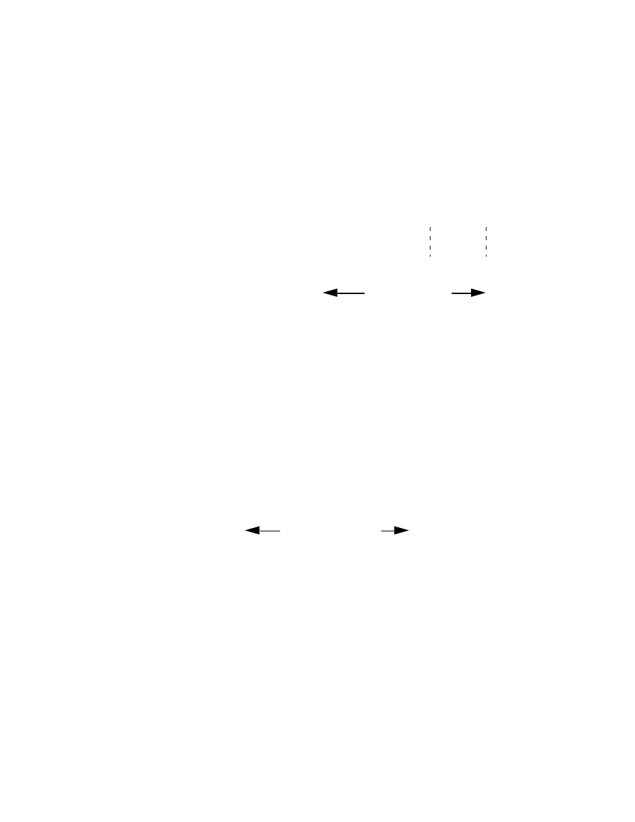
One solution to this problem was to allow a subnetted network to be assigned more than
one subnet mask. Assume that in the previous example, the network administrator is
also allowed to configure the 130.5.0.0/16 network with a /26 extended-network-prefix.
Please refer to Figure 16. A /16 network address with a /26 extended-network prefix
permits 1024 subnets (2
10
), each of which supports a maximum of 62 hosts (2
6
-2).
The /26 prefix would be ideal for small subnets with less than 60 hosts, while the /22
prefix is well suited for larger subnets containing up to 1000 hosts.
Wyszukiwarka
Podobne podstrony:
IP Address, Understanding IP Addressing Part III
=[ip address]=, Understanding IP Addressing2
NY 2 S Guide to Obtaining An IP Address
Routing Worm A Fast, Selective Attack Worm based on IP Address Information
#0246 – Understanding Addresses
Adresy IP
w8 VLAN oraz IP w sieciach LAN
ADRESACJA W SIECIACJ IP
SNMP (IP)
Adresy IP
ip 11 04
Microsoft PowerPoint IP tryb zgodnosci
CGEIB IP
ZAPROSZENIE, Documents, IP Zielona gora, mat inf
Podsumowanie pracy Zespołu Informacji Publicznej i Współpracy z innymi za rok 2015, Documents, ip, s
więcej podobnych podstron