60520-EN_Ver1.11.fm/2
Schneider Electric
Presentation
Soft starters
0
Altistart 48 soft start - soft stop units
1
2
7
5
6
4
3

60520-EN_Ver1.11.fm/3
Schneider Electric
Presentation
(continued)
Soft starters
0
Altistart 48 soft start - soft stop units
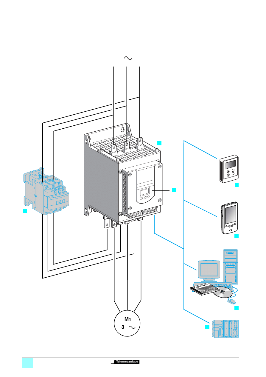
The Altistart 48 soft start - soft stop unit is a controller with 6 thyristors which is used
for the torque-controlled soft starting and stopping of three-phase squirrel cage
asynchronous motors in the power range between 4 and 1200 kW.
It offers soft starting and deceleration functions along with machine and motor
protection functions as well as functions for communicating with control systems.
These functions are designed for use in state-of-the-art applications in centrifugal
machines, pumps, fans, compressors and conveyors, which are primarily to be found
in the construction, food and beverages and chemical industries. The high-
performance algorithms of the Altistart 48 contribute significantly to its robustness,
safety and ease of setup.
The Altistart 48 soft start - soft stop unit is a cost-effective solution which can:
b
reduce machine operating costs by reducing mechanical stress and improving
machine availability,
b
reduce the stress placed on the electrical distribution system by reducing line
current peaks and voltage drops during motor starts.
The Altistart soft start - soft stop unit offer comprises 2 ranges:
b
three-phase voltages 230 to 415 V, 50/60 Hz,
b
three-phase voltages 208 to 690 V, 50/60 Hz.
In each voltage range, the Altistart soft start - soft stop units are dimensioned for
standard and severe applications.
The Altistart 48 soft start - soft stop unit (
) is supplied ready for use in a standard
application with motor protection class 10 (see page 60526/5).
It comprises a built-in terminal (
) which can be used to modify programming,
adjustment or monitoring functions in order to adapt and customise the application to
meet individual customer requirements.
b
Drive performance functions:
v
exclusive Altistart torque control (patented by Schneider Electric),
v
constant control of the torque supplied to the motor during acceleration and
deceleration periods (significantly reducing pressure surges),
v
facility for adjusting the ramp and the starting torque,
v
the starter can be bypassed using a contactor (
) at the end of the starting period
whilst maintaining electronic protection (bypass function),
v
wide frequency tolerance for generator set power supplies,
v
the starter can be connected to the motor delta terminals in series with each
winding.
b
Machine and motor protection functions:
v
built-in motor thermal protection,
v
processing of information from PTC thermal probes,
v
monitoring of the starting time,
v
motor preheating function,
v
protection against underloads and overcurrents during continuous operation.
b
Functions facilitating the integration of the unit into control systems:
v
4 logic inputs, 2 logic outputs, 3 relay outputs and 1 analogue output,
v
plug-in I/O connectors,
v
function for configuring a second motor and easy-to-adapt settings,
v
display of electrical values, the state of the load and the operating time,
v
RS 485 serial link for connection to Modbus.
A remote terminal (
) can be mounted on the door of a wall-fixing or floor-standing
enclosure.
PowerSuite advanced dialogue solutions:
b
PowerSuite Pocket PC with PPC type terminal (
),
b
PowerSuite software workshop (
).
A range of wiring accessories for connecting the starter to PLCs via a Modbus
connection (
).
Bus communication and Ethernet, Fipio, DeviceNet and Profibus DP network
communication options.
Applications
Functions
Options
1
2
3
4
5
6
7
Characteristics:
pages 60521/2 to 60521/5
References:
pages 60522/2 to 60522/5
Dimensions:
pages 60523/2 to 60523/5
Schemes:
pages 60524/2 to 60524/7
60521-EN_Ver1.12.fm/2
Schneider Electric
Characteristics
Soft starters
0
Altistart 48 soft start - soft stop units
Environment
Conformity to standards
The electronic starters have been developed and
performance tested in accordance with
international standards, in particular with the
starter product standard EN/IEC 60947-4-2.
e
marking
Products have CE marking in accordance with the
harmonised standard EN/IEC 60947-4-2.
Product approvals
UL, CSA
Pending: DNV, C-Tick, Gost, CCIB
Degree of protection
Starters ATS 48D17
p
to 48C11
p
IP 20 (IP 00 in the absence of connections)
Starters ATS 48C14
p
to 48M12
p
(1)
IP 00
Vibration resistance
Conforming to IEC 60068-2-6
1.5 mm from 2 to 13 Hz
1 gn from 13 to 200 Hz
Shock resistance
Conforming to IEC 60068-2-27
15 g for 11 ms
Starter noise level (2)
Starters ATS 48D32
p
to D47
p
dBA
52
Starters ATS 48D62
p
to C11
p
dBA
58
Starters ATS 48C14
p
to C17
p
dBA
50
Starters ATS 48C21
p
to C32
p
dBA
54
Starters ATS 48C41
p
to C66
p
dBA
55
Starters ATS 48C79
p
to M12
p
dBA
60
Fans
Starters ATS 48D17
p
and D22
p
Natural convection
Starters ATS 48D32
p
to M12
p
Forced convection. The fans are activated
automatically when a temperature threshold is
reached.
For flow rate see page 60523/5.
Ambient temperature around the unit
Operation
°C
- 10...+ 40 without derating (between + 40 and +
60, derate the nominal current of the Altistart by
2% for each °C).
Storage, conforming to
IEC 60947-4-2
°C
- 25...+ 70
Maximum relative humidity
Conforming to IEC 60068-2-3
95% without condensation or dripping water
Maximum ambient pollution
Conforming to IEC 60664-1
Level 3
Maximum operating altitude
m
1000 without derating (above this, derate the
nominal current of the Altistart by 2.2% for each
additional 100 m). Limit to 2000 m
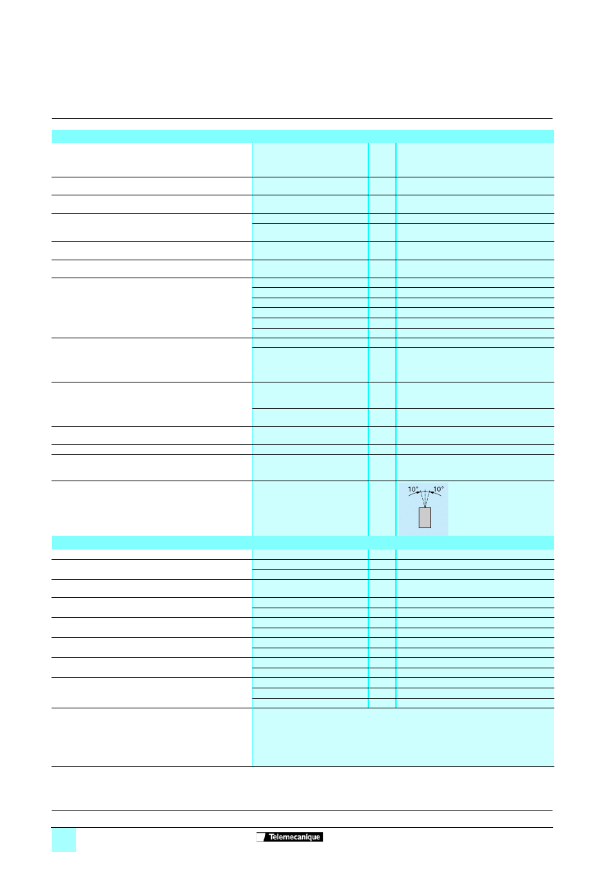
Operating position
Maximum permanent angle in relation to the normal vertical
mounting position
Electrical characteristics
Operating category
Conforming to IEC 60947-4-2
AC-53a
Three-phase supply voltage
Starters ATS 48
ppp
Q
V
230 -15% to 415 + 10%
Starters ATS 48
ppp
Y
V
208 - 15% to 690 + 10%
Frequency
Hz
50/60 ± 5% (automatic)
50 or 60 ± 20% (must be set)
Nominal starter current
Starters ATS 48
ppp
Q
A
17...1200
Starters ATS 48
ppp
Y
A
17 to 1200
Motor power
Starters ATS 48
ppp
Q
kW
4 to 630
Starters ATS 48
ppp
Y
kW/HP 5.5 to 900/5 to 1200
Voltage indicated on the motor rating plate
Starters ATS 48
ppp
Q
V
230 to 415
Starters ATS 48
ppp
Y
V
208 to 690
Starter control circuit supply voltage
Starters ATS 48
ppp
Q
V
220 - 15% to 415 + 10%, 50/60 Hz
Starters ATS 48
ppp
Y
V
110 - 15% to 230 + 10%, 50/60 Hz
Maximum control circuit consumption
(with fans operating)
Starters ATS 48D17
p
to C17
p
W
30
Starters ATS 48C21
p
to C32
p
W
50
Starters ATS 48C41
p
to M12
p
W
80
Relay output (2 configurable outputs)
3 relay outputs (R1, R2, R3), normally open contacts 1"N/O"
Minimum switching capacity: 10 mA for
c
6 V
Maximum switching capacity on inductive load: 1.8 A for
a
230 V
and
c
30 V (cos
ϕ
= 0.5 and L/R=20ms). Maximum nominal operating voltage
a
400 V
Factory setting: R1 assigned as the "fault relay" (configurable)
R2 assigned as the "end of starting relay" to control the starter bypass relay
R3 assigned as "motor powered" (configurable)
(1) Protective covers can be fitted to the power terminals of ATS 48C14
p
to C32
p
starters. ATS 48C41
p
to 48M12
p
starters have protection on the front panel and
on the sides.
(2) Starters located 1 m away. The noise levels may change depending on the characteristics of the fans.
Presentation:
pages 60520/2 and 60520/3
References:
pages 60522/2 to 60522/5
Dimensions:
pages 60523/2 to 60523/5
Schemes:
pages 60524/2 to 60524/7

60521-EN_Ver1.12.fm/3
Schneider Electric
Characteristics
(continued)
Soft starters
0
Altistart 48 soft start - soft stop units
Electrical characteristics
(continued)
Logic inputs LI (2 configurable inputs)
4 logic inputs, impedance 4.3 k
Ω,
isolated: Stop, Run, LI3, LI4
+ 24 V power supply (maximum 30 V) I max. 8 mA
State 0 if U < 5 V and I < 2 mA
State 1 if U > 11 V and I > 5 mA
Internal source available
1 x + 24 V output, isolated and protected against short-circuits and overloads
Accuracy ± 25%. Max. current 200 mA
Logic outputs LO (configurable)
2 logic outputs LO1 and LO2 with 0 V common, compatible with level 1 PLC, according
to standard IEC 65A-68
+ 24 V power supply (minimum: +12 V, maximum: + 30 V)
Maximum output current: 200 mA if supplied externally
Analogue output AO (configurable)
Current output 0-20 mA or 4-20 mA
Maximum load impedance: 500
Ω
Accuracy ± 5% of the maximum value
Input for PTC probe
Total resistance of probe circuit 750
Ω
at 25°C, according to IEC 60 738-A
Maximum I/O connection capacity
2.5 mm
2
(AWG 12)
Communication
RS 485 multidrop serial link integrated in the starter, for Modbus,
with RJ45 type connector
Transmission speed 4800, 9600 or 19200 bps
Maximum number of Altistart 48 connected: 18
Other uses:
- connection to a remote terminal, or
- connection to a PC, or
- connection to other buses and networks via communication options.
Protection
Thermal
Built-in, starter and motor (calculated and/or thermal protection with PTC probes)
Line protection
Phase failure, indicated by output relay
Current settings
The nominal motor current In can be adjusted from 0.4 to 1.3 times the starter nominal
current.
Adjustment of the maximum starting current from 1.5 to 7 times the motor In, limited to
5 times the starter nominal current.
Starting mode
By torque control with starter current limited to 5 In maximum
Factory setting: 4 In for standard operation on 15 s torque ramp
Stopping mode
Freewheel stop
"Freewheel" stop (factory setting)
Controlled stop on torque ramp
Programmed between 0.5 and 60 s (for pump applications)
Braked stop
Controlled dynamically by the flux
Electromagnetic compatibility EMC (1)
Standards
Test levels
Examples
(sources of interference)
Summary of immunity tests carried out with the Altistart 48
IEC 61000-4-2 level 3
Electrostatic discharge:
- by contact,
- in the air.
6 kV
8 kV
Contact off an electrically charged
individual
IEC 61000-4-3 level 3
Radiated electromagnetic fields
10 V/m
Equipment transmitting radio
frequencies
IEC 61000-4-4 level 4
Rapid electrical transients:
- power supply cables,
- control cables.
4 kV
2 kV
Opening/closing of a contactor
IEC 61000-4-5 level 3
Shock wave:
- phase/phase,
- phase/earth.
1 kV
2 kV
-
IEC 61000-4-12 level 3
Damped oscillating waves
1 kV - 1 M Hz
Oscillating circuit on the line supply
Radiated and conducted emissions
According to IEC 60947-4-2, class A, on all starters
According to IEC 60947-4-2, class B, on starters up to 170 A: ATS 48D17
p
to 48C17
p
.
Must be bypassed at the end of starting
(1) The starters conform to product standard IEC 60947-4-2, in particular with regard to EMC. This standard ensures a level of immunity for products and a level of
emitted interference. In steady state, the interference emitted is below that required by the standard. During acceleration and deceleration phases, low level
loads may be affected by low frequency interference (harmonics). To reduce this interference, connect chokes between the line supply and the Altistart 48 (see
page 60528/3).
Note:
b
Power factor correction capacitors can only be used upstream of the Altistart and only powered up at the end of starting.
b
The starter must be earthed to conform to the regulations concerning leakage currents (
y
30 mA). When the use of an upstream "residual
current device" for protection is required by the installation standards, an A-Si type device must be used. Check its compatibility with the other
protective devices. If the installation involves several starters on the same line supply, each starter must be earthed separately.
Presentation:
pages 60520/2 and 60520/3
References:
pages 60522/2 to 60522/5
Dimensions:
pages 60523/2 to 60523/5
Schemes:
pages 60524/2 to 60524/7
60521-EN_Ver1.12.fm/4
Schneider Electric
Characteristics
(continued)
Soft starters
0
Altistart 48 soft start - soft stop units
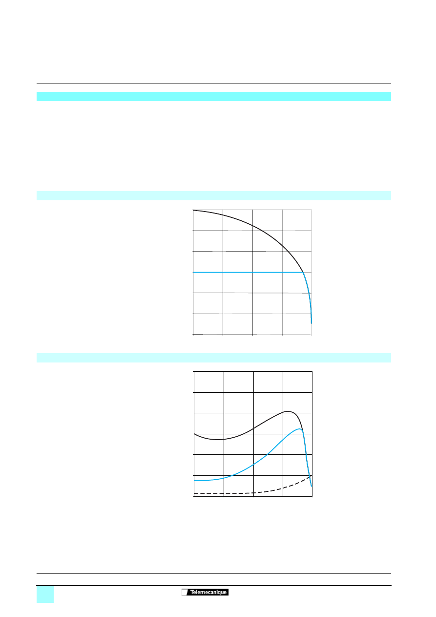
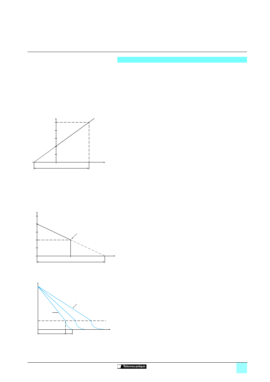
Torque characteristics
Curves indicating changes in the torque depending on the starting current of a three-
phase asynchronous motor.
Curves 1: direct line starting.
Curves 2: starting in current limiting mode.
Torque curve Ts1 indicates the total torque range available depending on the limiting
current Is1.
Limiting the starting current Is to a preset value Is1 will reduce the starting torque Ts1
to a value which is almost equal to the square of currents Is1/Is.
Example:
For motor characteristics: Ts = 3 Tn for Is = 6 In,
limit the current to Is1 = 3 In (0.5 Is)
resulting in a starting torque Ts1 = Ts x (0.5)² = 3 Tn x 0.25 = 0.75 Tn
Starting current
1
Direct line starting current
2
Starting current limited to Is1
Starting torque
1
Direct line starting torque
2
Starting torque with current limited
to Is1
6
5
4
3
2
1
0
0
1
0,25
0,5
0,75
N/Ns
I/In
Id1
1
2
0
1
0,25
0,5
0,75
Cd1
N/Ns
Cr
6
5
4
3
2
1
0
C/Cn
1
2
Presentation:
pages 60520/2 and 60520/3
References:
pages 60522/2 to 60522/5
Dimensions:
pages 60523/2 to 60523/5
Schemes:
pages 60524/2 to 60524/7
60521-EN_Ver1.12.fm/5
Schneider Electric
Characteristics
(continued)
Soft starters
0
Altistart 48 soft start - soft stop units
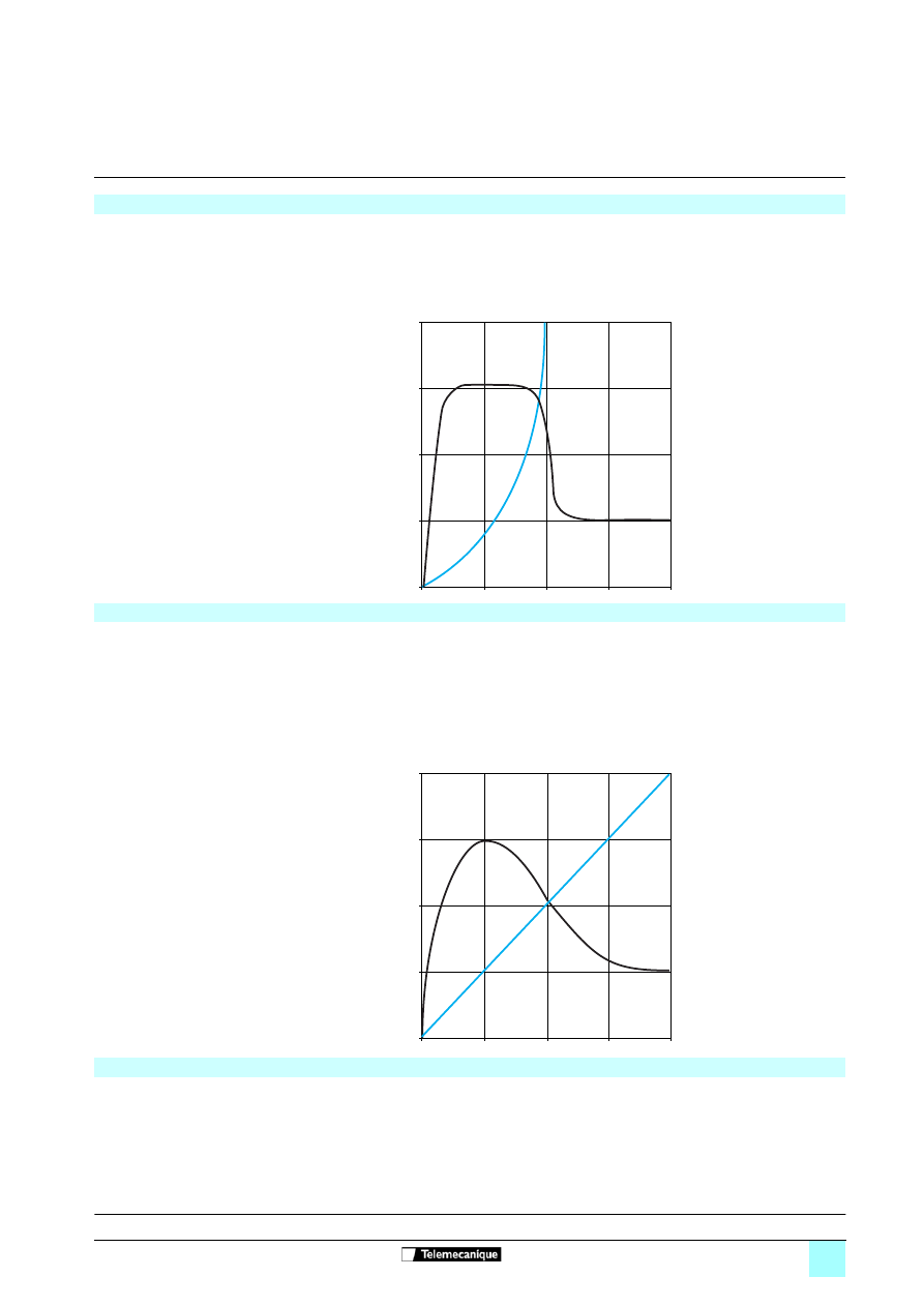
Conventional starting using current limitation or voltage ramp
With current limitation Is1, the accelerating torque applied to the motor is equal to the
motor torque Ts1 minus the resistive torque Tr.
The accelerating torque increases in the starting range as the speed changes and is
at its highest at the end of acceleration (curve 2).
This characteristic means that the load is taken up very abruptly, which is not
recommended for pump type applications.
Example of speed curve for starting with current
limitation
1
Current applied to the motor (I/In)
2
Motor speed N/Ns
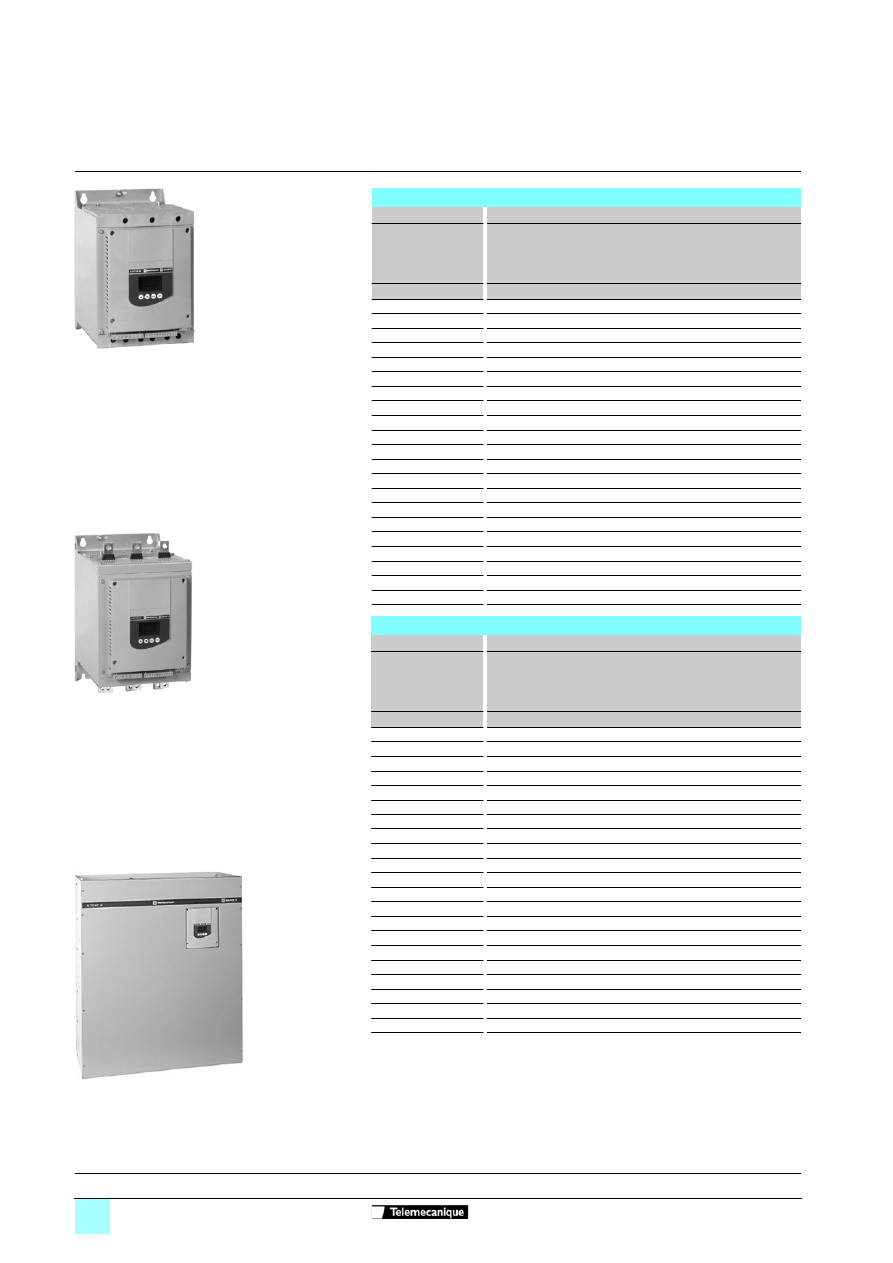
Starting with the Altistart 48
Torque control on the Altistart 48 applies the torque to the motor during the entire
starting phase if the current required (curve 1) does not exceed the limiting current.
The accelerating torque can be virtually constant over the entire speed range
(curve 2).
It is possible to set the Altistart in order to obtain a high torque on starting for a rapid
motor speed rise whilst limiting its temperature rise, and a lower accelerating torque
at the end of starting for gradual loading.
This control function is ideal for centrifugal pumps or for machines with high resistive
torque on starting.
Example of speed curve for starting with torque control
1
Current applied to the motor (I/In)
2
Motor speed N/Ns
Stopping with the Altistart 48
b
Freewheel stop: the motor comes to a freewheel stop.
b
Decelerated stop: this type of stop is ideal for pumps and can be used to effectively
reduce pressure surges. Torque control on the Altistart 48 reduces the effect of
hydraulic transients even if the load increases. This type of control makes adjustment
easy.
b
Braked stop: this type of stop is suitable for high inertia applications as it reduces
the stopping time of the machine.
t
4
1
3
2
0,5
1
0
I/In
N/Ns
1
2
4
1
3
2
0,5
1
0
I/In
N/Ns
1
2
t
Presentation:
pages 60520/2 and 60520/3
References:
pages 60522/2 to 60522/5
Dimensions:
pages 60523/2 to 60523/5
Schemes:
pages 60524/2 to 60524/7
60522-EN_Ver1.21.fm/2
Schneider Electric
References
Soft starters
0
Altistart 48 soft start - soft stop units
Line voltage 230/415 V
Connection in the motor supply line
For standard applications
Motor
Starter 230/415 V - 50/60 Hz
Motor power
Nominal
current
(IcL)
(2)
Factory
setting
current
(4)
Power
dissipated
at nominal
load
Reference
Weight
(1)
230 V
400 V
kW
kW
A
A
W
kg
4
7.5
17
14.8
59
ATS 48D17Q
4.900
5.5
11
22
21
74
ATS 48D22Q
4.900
7.5
15
32
28.5
104
ATS 48D32Q
4.900
9
18.5
38
35
116
ATS 48D38Q
4.900
11
22
47
42
142
ATS 48D47Q
4.900
15
30
62
57
201
ATS 48D62Q
8.300
18.5
37
75
69
245
ATS 48D75Q
8.300
22
45
88
81
290
ATS 48D88Q
8.300
30
55
110
100
322
ATS 48C11Q
8.300
37
75
140
131
391
ATS 48C14Q
12.400
45
90
170
162
479
ATS 48C17Q
12.400
55
110
210
195
580
ATS 48C21Q
18.200
75
132
250
233
695
ATS 48C25Q
18.200
90
160
320
285
902
ATS 48C32Q
18.200
110
220
410
388
1339
ATS 48C41Q
51.400
132
250
480
437
1386
ATS 48C48Q
51.400
160
315
590
560
1731
ATS 48C59Q
51.400
–
355
660
605
1958
ATS 48C66Q
51.400
220
400
790
675
2537
ATS 48C79Q
115.000
250
500
1000
855
2865
ATS 48M10Q
115.000
355
630
1200
1045
3497
ATS 48M12Q
115.000
For severe applications
Motor
Starter 230/415 V - 50/60 Hz
Motor power
Nominal
current
(3)
Factory
setting
current
(4)
Power
dissipated
at nominal
load
Reference
Weight
(1)
230 V
400 V
kW
kW
A
A
W
kg
3
5.5
12
14.8
46
ATS 48D17Q
4.900
4
7.5
17
21
59
ATS 48D22Q
4.900
5.5
11
22
28.5
74
ATS 48D32Q
4.900
7.5
15
32
35
99
ATS 48D38Q
4.900
9
18.5
38
42
116
ATS 48D47Q
4.900
11
22
47
57
153
ATS 48D62Q
8.300
15
30
62
69
201
ATS 48D75Q
8.300
18.5
37
75
81
245
ATS 48D88Q
8.300
22
45
88
100
252
ATS 48C11Q
8.300
30
55
110
131
306
ATS 48C14Q
12.400
37
75
140
162
391
ATS 48C17Q
12.400
45
90
170
195
468
ATS 48C21Q
18.200
55
110
210
233
580
ATS 48C25Q
18.200
75
132
250
285
695
ATS 48C32Q
18.200
90
160
320
388
1017
ATS 48C41Q
51.400
110
220
410
437
1172
ATS 48C48Q
51.400
132
250
480
560
1386
ATS 48C59Q
51.400
160
315
590
605
1731
ATS 48C66Q
51.400
–
355
660
675
2073
ATS 48C79Q
115.000
220
400
790
855
2225
ATS 48M10Q
115.000
250
500
1000
1045
2865
ATS 48M12Q
115.000
(1) Value indicated on the motor rating plate.
(2) Corresponds to the maximum permanent current in class 10. IcL corresponds to the starter
rating.
(3) Corresponds to the maximum permanent current in class 20.
(4) The factory setting current corresponds to the value of the nominal current of a standard
4-pole, 400 V, class 10 motor (standard application). Adjust the settings in accordance with
the motor nominal current.
106762
ATS 48D17Q
106761
ATS 48C14Q
ATS 48M12Q
106758
Presentation:
pages 60520/2 and 60520/3
Characteristics:
pages 60521/2 to 60521/5
Dimensions:
pages 60523/2 and 60523/3
Schemes:
pages 60524/2 to 60524/7
60522-EN_Ver1.21.fm/3
Schneider Electric
References
(continued)
Soft starters
0
Altistart 48 soft start - soft stop units
Line voltage 230/415 V
Connection to the motor delta terminals
For standard applications according to Figure 1
Motor
Starter 230/415 V - 50/60 Hz
Motor power
Nominal
current
(2)
Factory
setting
current
(4)
Power
dissipated
at nominal
load
Reference
Weight
(1)
230 V
400 V
kW
kW
A
A
W
kg
7.5
15
29
14.8
59
ATS 48D17Q
4.900
9
18.5
38
21
74
ATS 48D22Q
4.900
15
22
55
28.5
104
ATS 48D32Q
4.900
18.5
30
66
35
116
ATS 48D38Q
4.900
22
45
81
42
142
ATS 48D47Q
4.900
30
55
107
57
201
ATS 48D62Q
8.300
37
55
130
69
245
ATS 48D75Q
8.300
45
75
152
81
290
ATS 48D88Q
8.300
55
90
191
100
322
ATS 48C11Q
8.300
75
110
242
131
391
ATS 48C14Q
12.400
90
132
294
162
479
ATS 48C17Q
12.400
110
160
364
195
580
ATS 48C21Q
18.200
132
220
433
233
695
ATS 48C25Q
18.200
160
250
554
285
902
ATS 48C32Q
18.200
220
315
710
388
1339
ATS 48C41Q
51.400
250
355
831
437
1386
ATS 48C48Q
51.400
–
400
1022
560
1731
ATS 48C59Q
51.400
315
500
1143
605
1958
ATS 48C66Q
51.400
355
630
1368
675
2537
ATS 48C79Q
115.000
–
710
1732
855
2865
ATS 48M10Q
115.000
500
–
2078
1045
3497
ATS 48M12Q
115.000
For severe applications according to Figure 1
Motor
Starter 230/415 V - 50/60 Hz
Motor power
Nominal
current
(3)
Factory
setting
current
(4)
Power
dissipated
at nominal
load
Reference
Weight
(1)
230 V
400 V
kW
kW
A
A
W
kg
5.5
11
22
14.8
46
ATS 48D17Q
4.900
7.5
15
29
21
59
ATS 48D22Q
4.900
9
18.5
38
28.5
74
ATS 48D32Q
4.900
15
22
55
35
99
ATS 48D38Q
4.900
18.5
30
66
42
116
ATS 48D47Q
4.900
22
45
81
57
153
ATS 48D62Q
8.300
30
55
107
69
201
ATS 48D75Q
8.300
37
55
130
81
245
ATS 48D88Q
8.300
45
75
152
100
252
ATS 48C11Q
8.300
55
90
191
131
306
ATS 48C14Q
12.400
75
110
242
162
391
ATS 48C17Q
12.400
90
132
294
195
468
ATS 48C21Q
18.200
110
160
364
233
580
ATS 48C25Q
18.200
132
220
433
285
695
ATS 48C32Q
18.200
160
250
554
388
1017
ATS 48C41Q
51.400
220
315
710
437
1172
ATS 48C48Q
51.400
250
355
831
560
1386
ATS 48C59Q
51.400
–
400
1022
605
1731
ATS 48C66Q
51.400
315
500
1143
675
2073
ATS 48C79Q
115.000
355
630
1368
855
2225
ATS 48M10Q
115.000
–
710
1732
1045
2865
ATS 48M12Q
115.000
(1) Value indicated on the motor rating plate.
(2) Corresponds to the maximum permanent current in class 10.
(3) Corresponds to the maximum permanent current in class 20.
(4) For this type of connection. the factory setting current must be adjusted in accordance with
the nominal motor current.
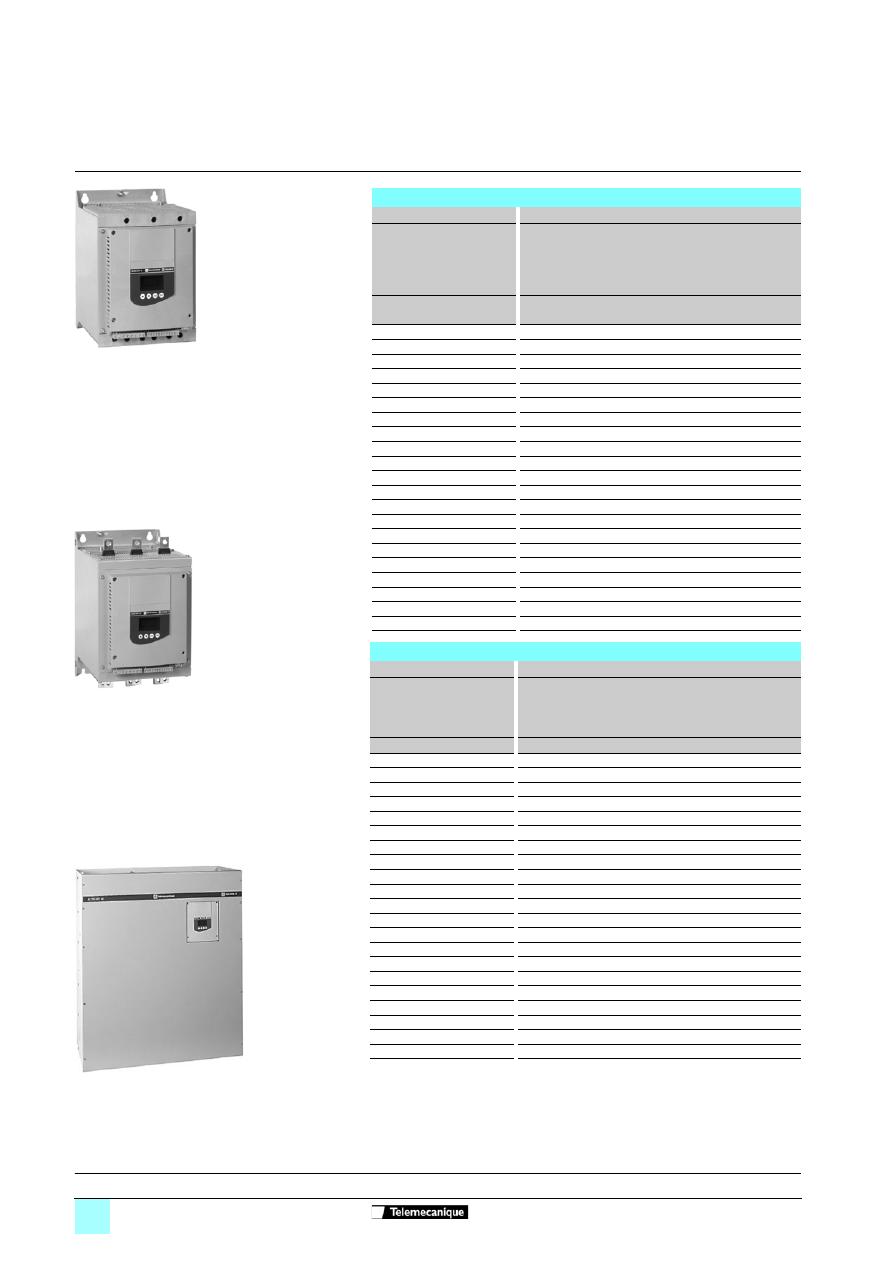
Figure 1
Special use:
Starter connected to the motor delta
terminal in series with each winding
ATS 48
ppp
Q
motor
Presentation:
pages 60520/2 and 60520/3
Characteristics:
pages 60521/2 to 60521/5
Dimensions:
pages 60523/2 and 60523/3
Schemes:
pages 60524/2 to 60524/7
60522-EN_Ver1.21.fm/4
Schneider Electric
References
(continued)
Soft starters
0
Altistart 48 soft start - soft stop units
Line voltage 208/690 V
Motor power in HP
For standard applications
Motor
Starter 208/690 V - 50/60 Hz
Motor power (1)
Nomina
l
current
(IcL)
(2)
Factory
setting
current(
4)
Power
dissipated
at nominal
load
Reference
Weigh
t
208 V 230 V 460 V 575 V
HP
HP
HP
HP
A
A
W
kg
3
5
10
15
17
14
59
ATS 48D17Y
4.900
5
7.5
15
20
22
21
74
ATS 48D22Y
4.900
7.5
10
20
25
32
27
104
ATS 48D32Y
4.900
10
–
25
30
38
34
116
ATS 48D38Y
4.900
–
15
30
40
47
40
142
ATS 48D47Y
4.900
15
20
40
50
62
52
201
ATS 48D62Y
8.300
20
25
50
60
75
65
245
ATS 48D75Y
8.300
25
30
60
75
88
77
290
ATS 48D88Y
8.300
30
40
75
100
110
96
322
ATS 48C11Y
8.300
40
50
100
125
140
124
391
ATS 48C14Y
12.400
50
60
125
150
170
156
479
ATS 48C17Y
12.400
60
75
150
200
210
180
580
ATS 48C21Y
18.200
75
100
200
250
250
240
695
ATS 48C25Y
18.200
100
125
250
300
320
302
902
ATS 48C32Y
18.200
125
150
300
350
410
361
1339
ATS 48C41Y
51.400
150
–
350
400
480
414
1386
ATS 48C48Y
51.400
–
200
400
500
590
477
1731
ATS 48C59Y
51.400
200
250
500
600
660
590
1958
ATS 48C66Y
51.400
250
300
600
800
790
720
2537
ATS 48C79Y
115.000
350
350
800
1000
1000
954
2865
ATS 48M10Y
115.000
400
450
1000
1200
1200
1170
3497
ATS 48M12Y
115.000
For severe applications
Motor
Starter 208/690 V - 50/60 Hz
Motor power (1)
Nominal
current
(3)
Factory
setting
current
(4)
Power
dissipated
at nominal
load
Reference
Weight
208 V 230 V 460 V 575 V
HP
HP
HP
HP
A
A
W
kg
2
3
7.5
10
12
14
46
ATS 48D17Y
4.900
3
5
10
15
17
21
59
ATS 48D22Y
4.900
5
7.5
15
20
22
27
74
ATS 48D32Y
4.900
7.5
10
20
25
32
34
99
ATS 48D38Y
4.900
10
–
25
30
38
40
116
ATS 48D47Y
4.900
–
15
30
40
47
52
153
ATS 48D62Y
8.300
15
20
40
50
62
65
201
ATS 48D75Y
8.300
20
25
50
60
75
77
245
ATS 48D88Y
8.300
25
30
60
75
88
96
252
ATS 48C11Y
8.300
30
40
75
100
110
124
306
ATS 48C14Y
12.400
40
50
100
125
140
156
391
ATS 48C17Y
12.400
50
60
125
150
170
180
468
ATS 48C21Y
18.200
60
75
150
200
210
240
580
ATS 48C25Y
18.200
75
100
200
250
250
302
695
ATS 48C32Y
18.200
100
125
250
300
320
361
1017
ATS 48C41Y
51.400
125
150
300
350
410
414
1172
ATS 48C48Y
51.400
150
–
350
400
480
477
1386
ATS 48C59Y
51.400
–
200
400
500
590
590
1731
ATS 48C66Y
51.400
200
250
500
600
660
720
2073
ATS 48C79Y
115.000
250
300
600
800
790
954
2225
ATS 48M10Y
115.000
350
350
800
1000
1000
1170
2865
ATS 48M12Y
115.000
(1) Value indicated on the motor rating plate.
(2) Corresponds to the maximum permanent current in class 10. IcL corresponds to the starter
rating.
(3) Corresponds to the maximum permanent current in class 20.
(4) The factory setting current corresponds to the value of the nominal current of a standard motor
according to NEC, 460 V, class 10 (standard application). Adjust the settings in accordance
with the motor nominal current.
ATS 48D17Y
1
0676
2
106761
ATS 48C14Y
ATS 48M12Y
1067
58
Presentation:
pages 60520/2 and 60520/3
Characteristics:
pages 60521/2 to 60521/5
Dimensions:
pages 60523/2 and 60523/3
Schemes:
pages 60524/2 to 60524/7

60522-EN_Ver1.21.fm/5
Schneider Electric
References
(continued)
Soft starters
0
Altistart 48 soft start - soft stop units
Line voltage 208/690 V
Motor power in kW
For standard applications
Motor
Starter 208/690 V - 50/60 Hz
Motor power (1)
Nominal
current
(IcL)
(2)
Factory
setting
current
(4)
Power
dissipated at
nominal load
Reference
Weight
230 V
400 V
440 V
500 V
525 V
660 V
690 V
kW
kW
kW
kW
kW
kW
kW
A
A
W
kg
4
7.5
7.5
9
9
11
15
17
14
59
ATS 48D17Y
4.900
5.5
11
11
11
11
15
18.5
22
21
74
ATS 48D22Y
4.900
7.5
15
15
18.5
18.5
22
22
32
27
104
ATS 48D32Y
4.900
9
18.5
18.5
22
22
30
30
38
34
116
ATS 48D38Y
4.900
11
22
22
30
30
37
37
47
40
142
ATS 48D47Y
4.900
15
30
30
37
37
45
45
62
52
201
ATS 48D62Y
8.300
18.5
37
37
45
45
55
55
75
65
245
ATS 48D75Y
8.300
22
45
45
55
55
75
75
88
77
290
ATS 48D88Y
8.300
30
55
55
75
75
90
90
110
96
322
ATS 48C11Y
8.300
37
75
75
90
90
110
110
140
124
391
ATS 48C14Y
12.400
45
90
90
110
110
132
160
170
156
479
ATS 48C17Y
12.400
55
110
110
132
132
160
200
210
180
580
ATS 48C21Y
18.200
75
132
132
160
160
220
250
250
240
695
ATS 48C25Y
18.200
90
160
160
220
220
250
315
320
302
902
ATS 48C32Y
18.200
110
220
220
250
250
355
400
410
361
1339
ATS 48C41Y
51.400
132
250
250
315
315
400
500
480
414
1386
ATS 48C48Y
51.400
160
315
355
400
400
560
560
590
477
1731
ATS 48C59Y
51.400
–
355
400
–
–
630
630
660
590
1958
ATS 48C66Y
51.400
220
400
500
500
500
710
710
790
720
2537
ATS 48C79Y
115.000
250
500
630
630
630
900
900
1000
954
2865
ATS 48M10Y
115.000
355
630
710
800
800
–
–
1200
1170
3497
ATS 48M12Y
115.000
For severe applications
Motor
Starter 208/690 V - 50/60 Hz
Motor power (1)
Nominal
current
(3)
Factory
setting
current
(4)
Power
dissipated at
nominal load
Reference
Weight
230 V
400 V
440 V
500 V
525 V
660 V
690 V
kW
kW
kW
kW
kW
kW
kW
A
A
W
kg
3
5.5
5.5
7.5
7.5
9
11
12
14
46
ATS 48D17Y
4.900
4
7.5
7.5
9
9
11
15
17
21
59
ATS 48D22Y
4.900
5.5
11
11
11
11
15
18.5
22
27
74
ATS 48D32Y
4.900
7.5
15
15
18.5
18.5
22
22
32
34
99
ATS 48D38Y
4.900
9
18.5
18.5
22
22
30
30
38
40
116
ATS 48D47Y
4.900
11
22
22
30
30
37
37
47
52
153
ATS 48D62Y
8.300
15
30
30
37
37
45
45
62
65
201
ATS 48D75Y
8.300
18.5
37
37
45
45
55
55
75
77
245
ATS 48D88Y
8.300
22
45
45
55
55
75
75
88
96
252
ATS 48C11Y
8.300
30
55
55
75
75
90
90
110
124
306
ATS 48C14Y
12.400
37
75
75
90
90
110
110
140
156
391
ATS 48C17Y
12.400
45
90
90
110
110
132
160
170
180
468
ATS 48C21Y
18.200
55
110
110
132
132
160
200
210
240
580
ATS 48C25Y
18.200
75
132
132
160
160
220
250
250
302
695
ATS 48C32Y
18.200
90
160
160
220
220
250
315
320
361
1017
ATS 48C41Y
51.400
110
220
220
250
250
355
400
410
414
1172
ATS 48C48Y
51.400
132
250
250
315
315
400
500
480
477
1386
ATS 48C59Y
51.400
160
315
355
400
400
560
560
590
590
1731
ATS 48C66Y
51.400
–
355
400
–
–
630
630
660
720
2073
ATS 48C79Y
115.000
220
400
500
500
500
710
710
790
954
2225
ATS 48M10Y
115.000
250
500
630
630
630
900
900
1000
1170
2865
ATS 48M12Y
115.000
(1) Value indicated on the motor rating plate.
(2) Corresponds to the maximum permanent current in class 10. IcL corresponds to the starter rating.
(3) Corresponds to the maximum permanent current in class 20.
(4) The factory setting current corresponds to the value of the nominal current of a standard motor according to NEC, 460 V, class 10 (standard application). Adjust
the settings in accordance with the motor nominal current.
Presentation:
pages 60520/2 and 60520/3
Characteristics:
pages 60521/2 to 60521/5
Dimensions:
pages 60523/2 and 60523/3
Schemes:
pages 60524/2 to 60524/7
60523-EN_Ver1.11.fm/2
Schneider Electric
Dimensions
Soft starters
0
Altistart 48 soft start - soft stop units
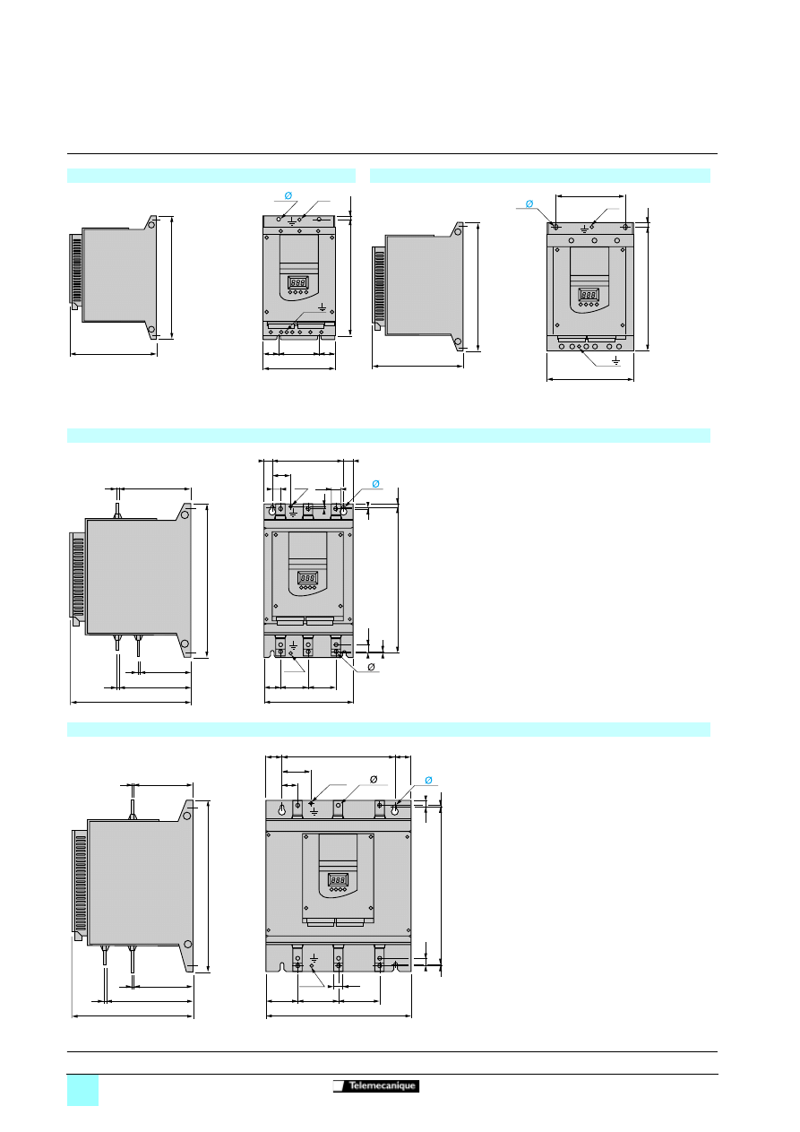
ATS 48D17
p
to ATS 48D47
p
ATS 48D62
p
to ATS 48C11
p
Maximum connection capacity:
Earth connections: 10 mm
2
(AWG 8)
Power terminals: 16 mm
2
(AWG 8)
Maximum connection capacity:
Earth connections: 16 mm
2
(AWG 4)
Power terminals: 50 mm
2
(AWG 2/0)
ATS 48C14
p
to ATS 48C17
p
Maximum connection capacity:
Earth connections: 120 mm
2
(busbar)
Power terminals: 95 mm
2
(AWG 2/0)
ATS 48C21
p
to ATS 48C32
p
Maximum connection capacity:
Earth connections: 120 mm2 (busbar)
Power terminals: 240 mm2 (busbar)
190
100
=
=
260
6,6
160
275
4x
M6
7
M6
235
190
150
4x 7
270
10
290
M6
M6
M6
1/L1
3/L2
5/L3
18
2
40
160
=
=
20
M6
5
116,5
5
159
5
162
265
38
62
62
200
14
1
320
10
1
340
4x 7
9x 8
1/L1
3/L2
5/L3
35
66
250
=
=
20
5
5
136,5
136,5
5
196,5
265
M10
70
90
320
90
18
10
350
12
380
4x 9
9x 12
M10
Presentation:
pages 60520/2 and 60520/3
Characteristics:
pages 60521/2 and 60521/3
References:
pages 60522/2 to 60522/5
Schemes:
pages 60524/2 to 60524/7
60523-EN_Ver1.11.fm/3
Schneider Electric
Dimensions
(continued)
Soft starters
0
Altistart 48 soft start - soft stop units
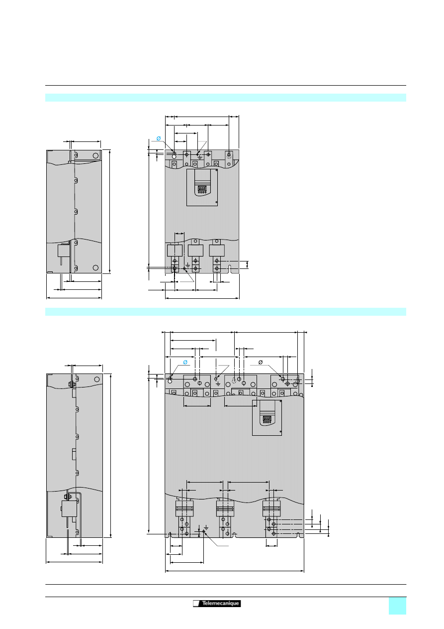
ATS 48C41
p
to C66
p
Maximum connection capacity:
Earth connections:
240 mm
2
(busbar)
Power terminals:
2 x 240 mm
2
(busbar)
ATS 48C79
p
to M12
p
Maximum connection
capacity:
Earth connections:
2 x 240 mm
2
(busbar)
Power terminals:
4 x 240 mm
2
(busbar)
5
165
670
M10
115
400
40
50,25
69
300
=
=
5
0,25
115
40
58
300
216
5
5
165
127
120
115
115
20
610
1L1
5L3
3L2
1,5
4x 9
M10
26
26
24
60
95
188
5
170
890
60
26
180
155
164
129
257
350
=
=
350
26
26
223,5
209,5
26
2
850
20
770
315
196,5
116,5
5
5
5
26
26
26
204
228
6x 9
18x 14
M10
M10
Presentation:
pages 60520/2 and 60520/3
Characteristics:
pages 60521/2 and 60521/3
References:
pages 60522/2 to 60522/5
Schemes:
pages 60524/2 to 60524/7
60523-EN_Ver1.11.fm/4
Schneider Electric
Dimensions
(continued)
Soft starters
0
Altistart 48 soft start - soft stop units
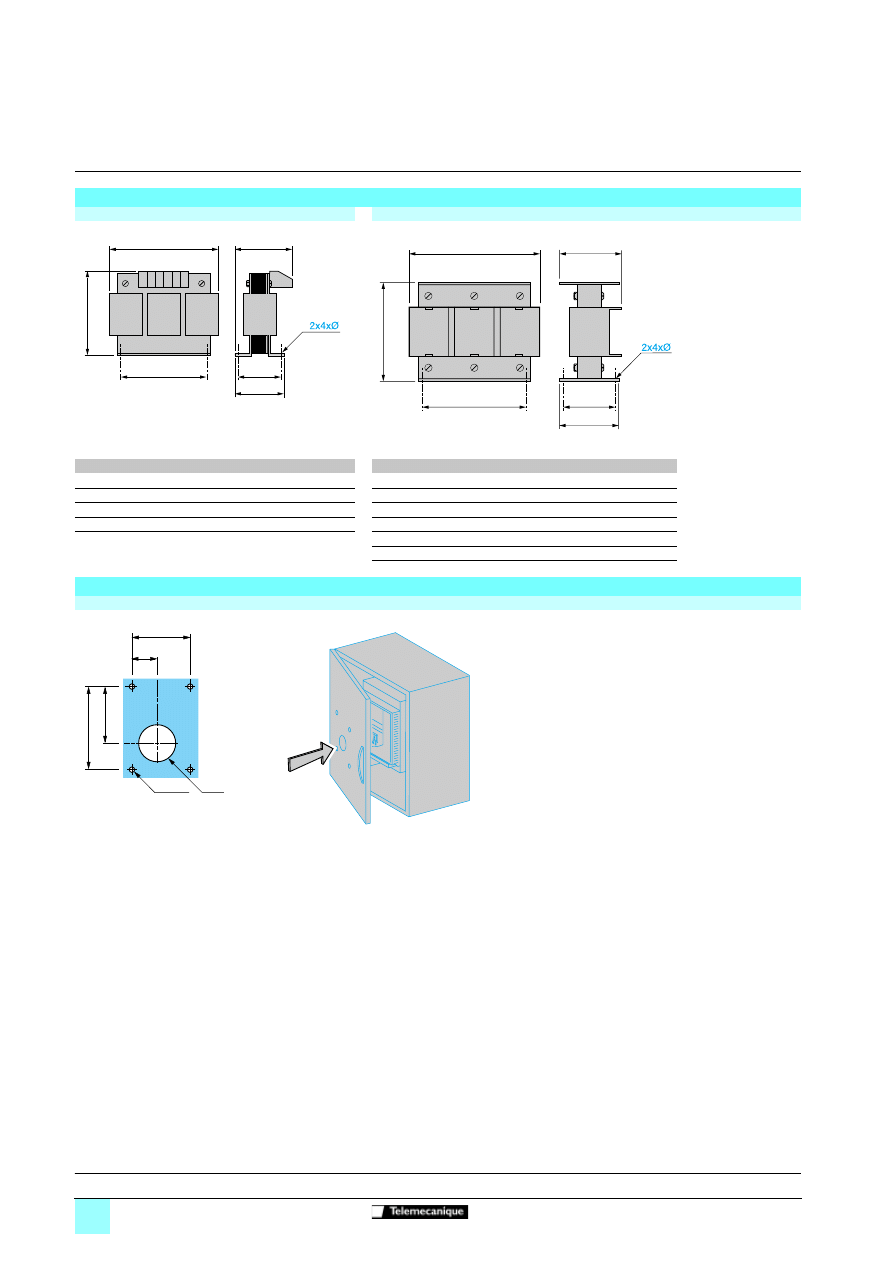
Chokes
VZ1-L015UM17T to L070U350T
VZ1-L15OU170T to LM14U016T
VZ1-
a
b
c
c1
G
H
Ø
VZ1-
a
b
c
c1
G
H
Ø
L015UM17T 120
150
80
75
60/80.5
52 6
L150U170T 270
240
170
140
105/181 96
11.5
L030U800T 150
180
120
100
75/106.5 76 7
L250U100T 270
240
220
160
105/181 125
11.5
L040U600T 180
215
130
100
85/122
76 7
L325U075T 270
240
240
175
105/181 138
11.5
L070U350T 180
215
150
130
85/122
97 7
L530U045T 380
410
225
140
310
95
9
LM10U024T 400
410
310
170
310
125
9
LM14U016T 420
490
340
170
310
125
9
H
c
a
G
b
c1
a
c
G
H
b
c1
Presentation:
pages 60520/2 and 60520/3
Characteristics:
pages 60521/2 and 60521/3
References:
pages 60522/2 to 60522/5
Schemes:
pages 60524/2 to 60524/7
Mounting the remote terminal
VW3 G48101
55,6
24
79,6
52
Ø36
A
4xØ3,5
60523-EN_Ver1.11.fm/5
Schneider Electric
Mounting
Soft starters
0
Altistart 48 soft start - soft stop units
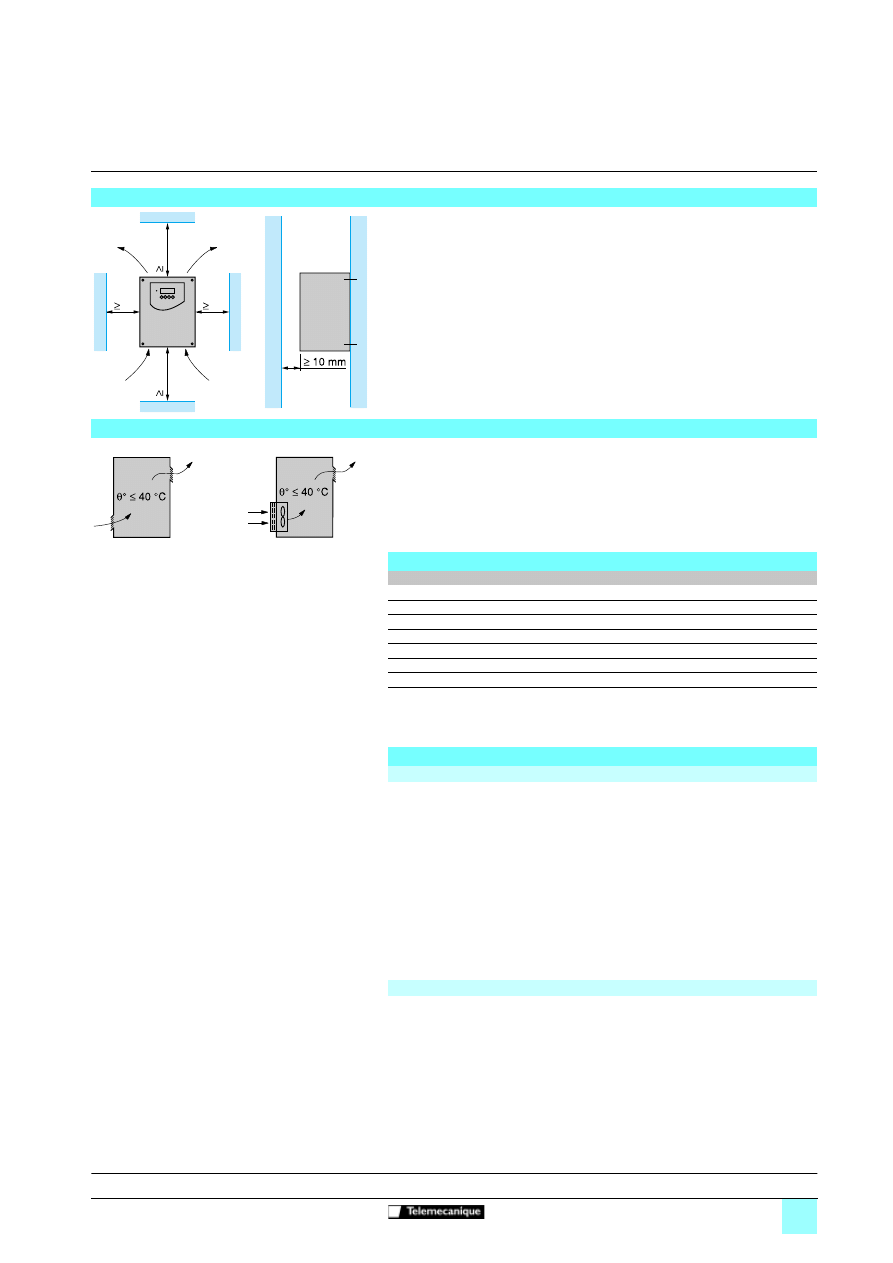
b
Install the Altistart vertically, at ± 10°.
b
Do not place the Altistart close to or above heating elements.
b
Leave sufficient free space to ensure that the air required for cooling purposes can
circulate from the bottom to the top of the unit.
Caution: The IP 00 version of the Altistart 48 must be fitted with a protective bar to
protect personnel against electrical contact.
Protective covers are available for the ATS 48C14
p
to ATS 48C32
p
. They should be
ordered separately.
b
Observe the mounting recommendations above.
b
To ensure proper air circulation in the starter:
v
fit ventilation grilles,
v
ensure that there is sufficient ventilation. If there is not, install forced ventilation
with a filter ; the openings and/or fans must provide a flow rate at least equal to that
of the starter fans (see the table below).
b
Use special filters with IP 54 protection.
Metal wall-fixing or floor-standing enclosure with IP 54 degree of protection
For non-ventilated Altistart units (ATS 48D17
p
and 48D22
p
), install a fan
y
50 mm
below the starter to circulate the air inside the enclosure in order to avoid hot spots.
θ
= maximum temperature inside enclosure in °C
θ
e = maximum external temperature in °C
P = total power dissipated in the enclosure in W
The starter/motor combinations on pages 60522/2 and 60522/3 can only be used in
ambient temperatures
y
40°C.
For temperatures between 40°C and 60°C, derate the maximum permanent current
of the starter by 2% for every degree above 40°C.
Power dissipated by the starter: see pages 60522/2 and 60522/3.
If the starts are infrequent, it is advisable to bypass the Altistart at the end of starting
in order to reduce heat dissipation.
The power dissipated will then be between 15 and 30 W.
Add the power dissipated by the other equipment components.
(sides + top + front panel if wall-mounted)
K is the thermal resistance per m
2
of casing.
For ACM type metal enclosures: K = 0.12 with internal fan, K = 0.15 without fan.
Caution: Do not use insulated enclosures as they have a poor level of conductivity.
Mounting recommendations
50
mm
50
mm
100 mm
100 mm
Mounting in a metal wall-fixing or floor-standing enclosure with degree of protection IP 23 or IP 54
Fan flow rate depending on the starter rating
ATS 48 starter
Flow rate m
3
/hour
ATS48 D32
p
and D38
p
14
ATS48 D47
p
28
ATS48 D62
p
to C11
p
86
ATS48 C14
p
and C17
p
138
ATS48 C21
p
to C32
p
280
ATS48 C41
p
to C66
p
600
ATS48 C29
p
to M12
p
1200
Calculating the size of the enclosure
Maximum thermal resistance Rth (°C/W)
Rth
θ θ
e
–
P
----------------
=
Effective exchange surface area of enclosure S (m
2
)
SS
K
Rth
----------
=
Presentation:
pages 60520/2 and 60520/3
Characteristics:
pages 60521/2 and 60521/3
References:
pages 60522/2 to 60522/5
Schemes:
pages 60524/2 to 60524/7

60526-EN_Ver1.12.fm/2
Schneider Electric
Functions
Soft starters
0
Altistart 48 soft start - soft stop units
The starter is supplied ready for use in most applications. The main functions
enabled and the default function values are as follows:
- nominal motor current (depends on the starter rating),
- limiting current: 400%,
- acceleration ramp time: 15 s,
- initial starting torque: 20%,
- selection of the type of stop: freewheel stop,
- motor thermal protection: class 10,
- time before restarting: 2 s,
- motor phase loss threshold: 10%,
- line frequency: automatic,
- RUN and STOP logic inputs: 2-wire or 3-wire control via wiring,
- logic input LI3: forced freewheel stop,
- logic input LI4: local mode control (serial link disabled),
- logic output LO1: thermal motor alarm,
- logic output LO2: motor powered,
- relay output R1: fault relay,
- relay output R3: motor powered,
- analogue output: motor current.
Summary of functions
See pages
Starter factory setting
60526/2
Adjustment functions
See pages
Nominal motor current (maximum permanent current)
60526/3
Limiting current
60526/3
Acceleration ramp time
60526/3
Initial starting torque
60526/3
Selection of the type of stop
60526/3
Protection functions
See pages
Calculated motor thermal protection
60526/4
Reset motor thermal state
60526/4
Motor thermal protection with PTC probes
60526/4
Starter thermal protection
60526/4
Motor underload protection
60526/5
Excessive acceleration time protection
60526/5
Current overload protection
60526/5
Protection against line phase inversion
60526/5
Time before restarting
60526/5
Motor phase loss detection
60526/5
Automatic restart
60526/5
Advanced adjustment functions
See pages
Torque limit
60526/6
Voltage boost level
60526/6
Connecting the starter to the motor delta terminals
60526/6
Test on low power motor
60526/6
Activation of the cascade function
60526/6
Line frequency
60526/6
Reset kWh or the operating time
60526/6
Return to factory settings
60526/6
2
nd
motor adjustment functions
60526/7
Communication functions
60526/7
PowerSuite advanced dialogue solutions
60526/7
Application monitoring functions
60526/7
Logic input application functions
See pages
2-wire/3-wire control
60526/8
Freewheel stop
60526/8
External fault
60526/8
Motor preheating
60526/8
Force to local control mode
60526/8
Inhibit all protection
60526/8
Reset motor thermal fault
60526/8
Activation of the cascade function
60526/8
Reset all faults
60526/8
Logic output application functions
60526/9
Relay and analogue output application functions
60526/9
Function compatibility table
60526/9
Starter factory setting
Current setting with PowerSuite on
PPC
60526-EN_Ver1.12.fm/3
Schneider Electric
Functions
(continued)
Soft starters
0
Altistart 48 soft start - soft stop units
b
Nominal motor current (maximum permanent current)
The nominal current of the starter can be adapted to the nominal motor current
indicated on the rating plate.
Adjustment range: 0.4 to 1.3 times the starter nominal current.
b
Limiting current
The maximum starting current can be adjusted.
Adjustment range: 150% to 700% of the nominal motor current set and limited to
500% of the maximum permanent current defined for the starter rating.
b
Acceleration ramp time
During the starting phase, the Altistart 48 applies a torque ramp to the motor. The
time (ACC) set corresponds to the time taken by the ramp to reach the nominal
torque (starting at 0). Adjustment range: 1 to 60 s.
b
Initial starting torque
The initial torque tq0 applied to the motor can be used to instantly overcome any
resistive starting torque. Adjustment range: 0 to 100% of the nominal motor torque.
b
Selection of the type of stop
Three types of stop are available for selection:
v
Freewheel motor stop
v
Motor stop by deceleration via torque control (pump application) This type of
stop enables a centrifugal pump to be decelerated gradually on a ramp in order to
avoid a sudden stop. It can be used to dampen the hydraulic transient in order to
significantly reduce pressure surges.
The deceleration ramp time (dEC) can be adjusted.
During deceleration, the pump flow rate decreases and becomes negligible at a
certain speed. To continue to decelerate would serve no purpose. A torque threshold
(EdC) can be set at which the motor will change to freewheel stop mode, avoiding
the unnecessary heating of the motor and the pump.
v
Dynamic braking motor stop (application: stopping high inertia machines)
This type of stop will decelerate the motor if there is considerable inertia.
The braking torque level (brc) can be adjusted. The dynamic braking time (T1)
corresponds to the time taken to decelerate from 100% to 20% of the nominal motor
speed. To improve braking at the end of deceleration, the starter injects a d.c. current
for an adjustable period of time (T2).
Adjustment functions
100
tq0 = 40
80
60
40
20
0
0
% Cn
ACC
t
Acceleration ramp during time ACC with initial starting
torque Iq0 = 40% of the nominal motor torque
100
80
60
40
20
0
dEC
EdC
% Cn
t
Fin de décélération controlée
Decelerated stop by torque control during time dEC with
threshold Edc for changing to freewheel stop mode
Edc = 40% of nominal motor torque
End of controlled deceleration
100 %
20 %
0
T1
T2
brc = 20
brc = 100
t
Dynamic braking stops for different braking torque levels brc
60526-EN_Ver1.12.fm/4
Schneider Electric
Functions
(continued)
Soft starters
0
Altistart 48 soft start - soft stop units
The Altistart 48 offers functions for protecting the motor and the machine.
b
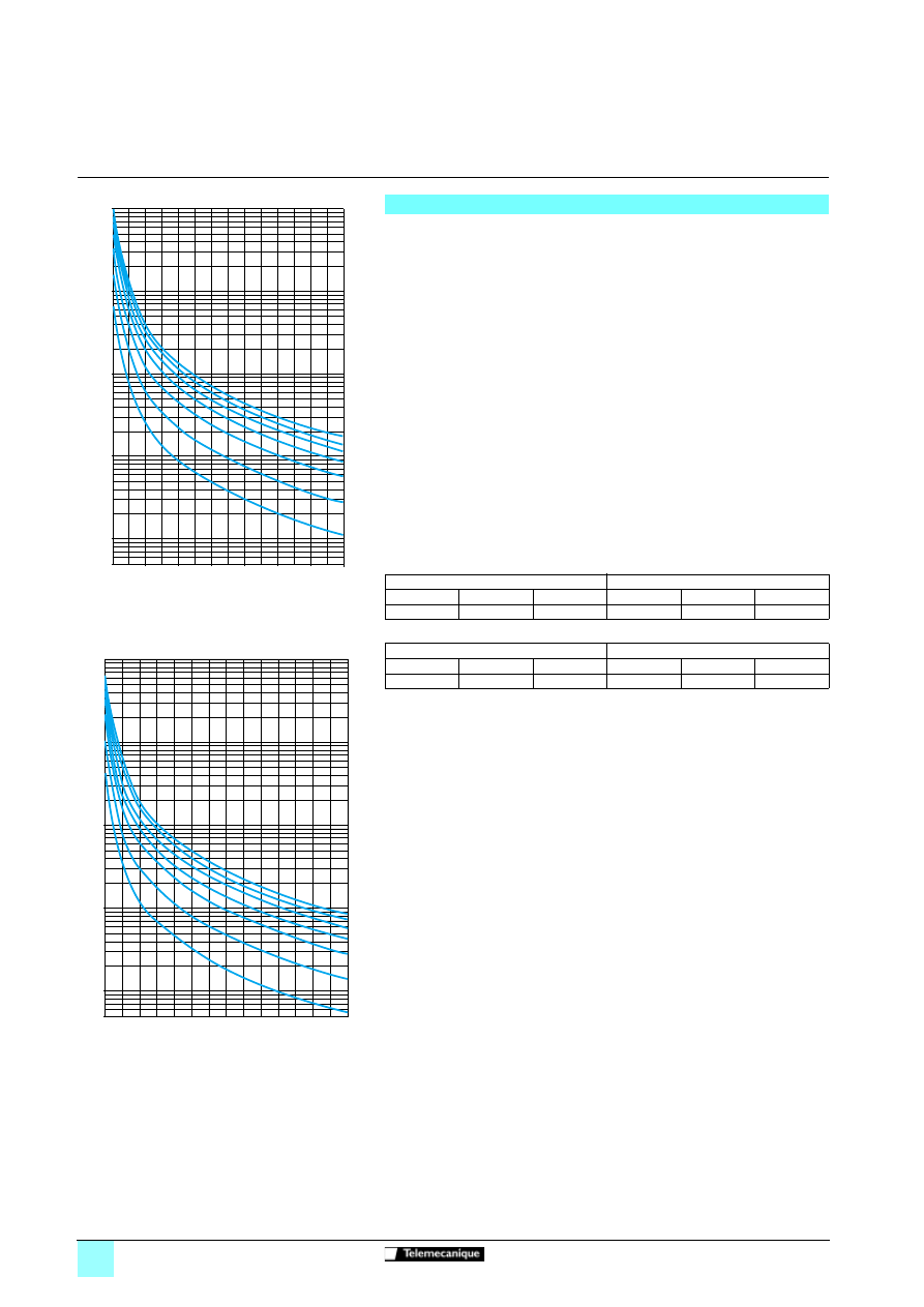
Calculated motor thermal protection
The starter continuously calculates the temperature rise of the motor based on the
nominal current which has been set and the actual current absorbed. In order to
adapt the Altistart to individual motors and applications, several protection classes
are offered in accordance with standard IEC 60947-4-2:
class 30, class 25, class 20 (severe application), class 15, class 10 (standard
application), class 10 A, sub-class 2.
Different protection classes are defined for the starting capacities of the motor:
- cold start without thermal fault (corresponding to a stabilised motor thermal state,
motor switched off),
- warm start without thermal fault (corresponding to a stabilised motor thermal
state, at nominal power).
The motor thermal protection function can be disabled.
After the motor has stopped or the starter has been switched off, the thermal state is
calculated even if the control circuit is not energised. The Altistart thermal control
prevents the motor from restarting if the temperature rise is too high. If special motors
are used which do not have thermal protection via curves, provide external thermal
protection via probes or thermal overload relays.
The starter is factory-set to protection class 10.
The tripping curves are based on the relationship between the starting current Is and
the (adjustable) nominal motor current In.
Trip time (cold)
Trip time (warm)
b
Reset motor thermal state
Activating the function resets the motor thermal state calculated by the starter to
zero.
b
Motor thermal protection with PTC probes
The starter integrates the processing of PTC probes, thus avoiding the use of an
external device. The "PTC probe thermal overshoot" fault or alarm can be indicated
using a configurable logic output or displayed via the serial link. The function can be
disabled.
Note: The "PTC probe protection" and "calculated motor thermal protection"
functions are independent and can be active simultaneously.
b
Starter ventilation: The cooling fan on the starter is switched on as soon as the
heatsink temperature reaches 50°C. It is switched off when the temperature returns
to 40°C.
b
Starter thermal protection
The starter is protected against thermal overloads by an analogue thermal probe.
Protection functions
0,5
1
10
100
1000
10000
t(s)
8,00
Id/In
7,00
6,00
5,00
4,00
3,00
2,00
1,12
30
25
20
15
10
10 A
2
Class
Motor thermal protection curves (cold)
0,5
1
10
100
1000
10000
t(s)
8,00
Id/In
7,00
6,00
5,00
4,00
3,00
2,00
1,12
30
25
20
15
10
10 A
2
Class
Motor thermal protection curves (warm)
Trip time for a standard application (class 10)
Trip time for a severe application (class 20)
Is = 3 In
Is = 4 In
Is = 5 In
Is = 3.5 In
Is = 4 In
Is = 5 In
46 s
23 s
15 s
63 s
48 s
29 s
Trip time for a standard application (class 10)
Trip time for a severe application (class 20)
Is = 3 In
Is = 4 In
Is = 5 In
Is = 3.5 In
Is = 4 In
Is = 5 In
23 s
12 s
7.5 s
32 s
25 s
15 s
60526-EN_Ver1.12.fm/5
Schneider Electric
Functions
(continued)
Soft starters
0
Altistart 48 soft start - soft stop units
b
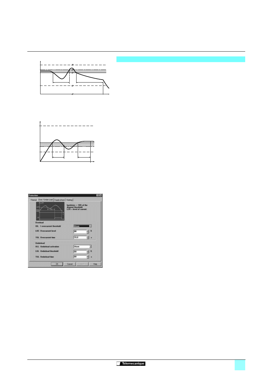
Motor underload protection
The starter detects a motor underload if the motor torque falls below a preset torque
threshold (LUL) for a specific (adjustable) period of time (tUL).
The motor underload threshold can be set between 20% and 100% of the nominal
motor torque. The permissible underload duration can be set between 1 and 60 s.
The detection function can trigger an alarm or a fault. The detection function can be
disabled. The "motor underload detected" alarm can be indicated by a configurable
logic output and/or displayed via the serial link in the state of the starter.
The "motor underload detected" fault (ULF) locks the starter and can be displayed
via the serial link.
b
Excessive acceleration time protection
This protection function can be used to detect a start which takes place in adverse
conditions. Examples of such conditions include a locked rotor or a motor unable to
reach its nominal rotation speed.
If the start duration is greater than the value set (between 10 and 999 s),
the drive changes to fault mode. The function can be disabled.
b
Current overload protection
The starter detects a current overload if the motor current exceeds a preset
overcurrent threshold (LOC) for a specific (adjustable) period of time (tOL).
The overcurrent threshold can be set between 50% and 300% of the nominal motor
current.
The permissible overcurrent duration can be set between 0.1 and 60 s.
This function is only active in steady state.
The detection function can trigger an alarm or a fault. It can also be disabled.
The "current overload detected" alarm can be indicated by a configurable logic output
and/or displayed via the serial link.
The "current overload detected" fault (OLC) locks the starter and can be displayed
via the serial link in the state of the starter.
b
Protection against line phase inversion
This function can be used to detect the direction of rotation of the motor phases and,
if it is enabled, to indicate a fault when the direction of rotation is reversed.
b
Time before restarting
This function can be used to avoid several consecutive starts which may cause:
- the thermal overheating of the application, which is not permitted,
- a thermal fault which will require maintenance work to be carried out,
- overcurrents (if the direction of rotation is reversed) or repeats (run/stop
commands).
Following a stop command, the motor can only restart once the preset time delay has
elapsed.
The motor is restarted once the time delay has elapsed if a run command is still valid
or if a new run command is sent.
Adjustment range: 0 to 999 s.
b
Motor phase loss detection
The function is used to adjust the sensitivity of the protection function in order to
detect a loss of current or a low current in one of the three motor phases for at least
0.5 s or in all three motor phases for at least 0.2 s. The value of the minimum current
level can be set between 5% and 10% of the starter nominal current.
b
Automatic restart
After locking on a fault, the function permits up to six restart attempts at intervals of
60 s if the fault has disappeared and the run commands are still present. After the
sixth attempt, the starter will remain locked and the fault will have to be reset before
a restart is permitted.
If the function is active, the fault relay remains activated if line phase loss, motor
phase loss or line frequency out of tolerance faults are detected. This function can
only be used in 2-wire control.
Protection functions
(continued)
20 %
(Cn) 100 %
t
C
LUL + 10 %
ULL
t < tUL
tUL
LUL
Motor underload detection (ULL)
50 %
300 %
I
t
OIL
tOL
t < tOL
LOC -10 %
LOC
Motor overcurrent detection (OIL)
Configuring the starter overload and underload with
PowerSuite on a PC
60526-EN_Ver1.12.fm/6
Schneider Electric
Functions
(continued)
Soft starters
0
Altistart 48 soft start - soft stop units
b
Torque limit
Designed primarily for high inertia and constant torque conveyor applications , the
function restricts the torque ramp reference to the preset value.
For example, the function can be used to limit the torque to a constant value
throughout the starting period.
Adjustment range: 10% to 200% of the nominal motor torque.
b
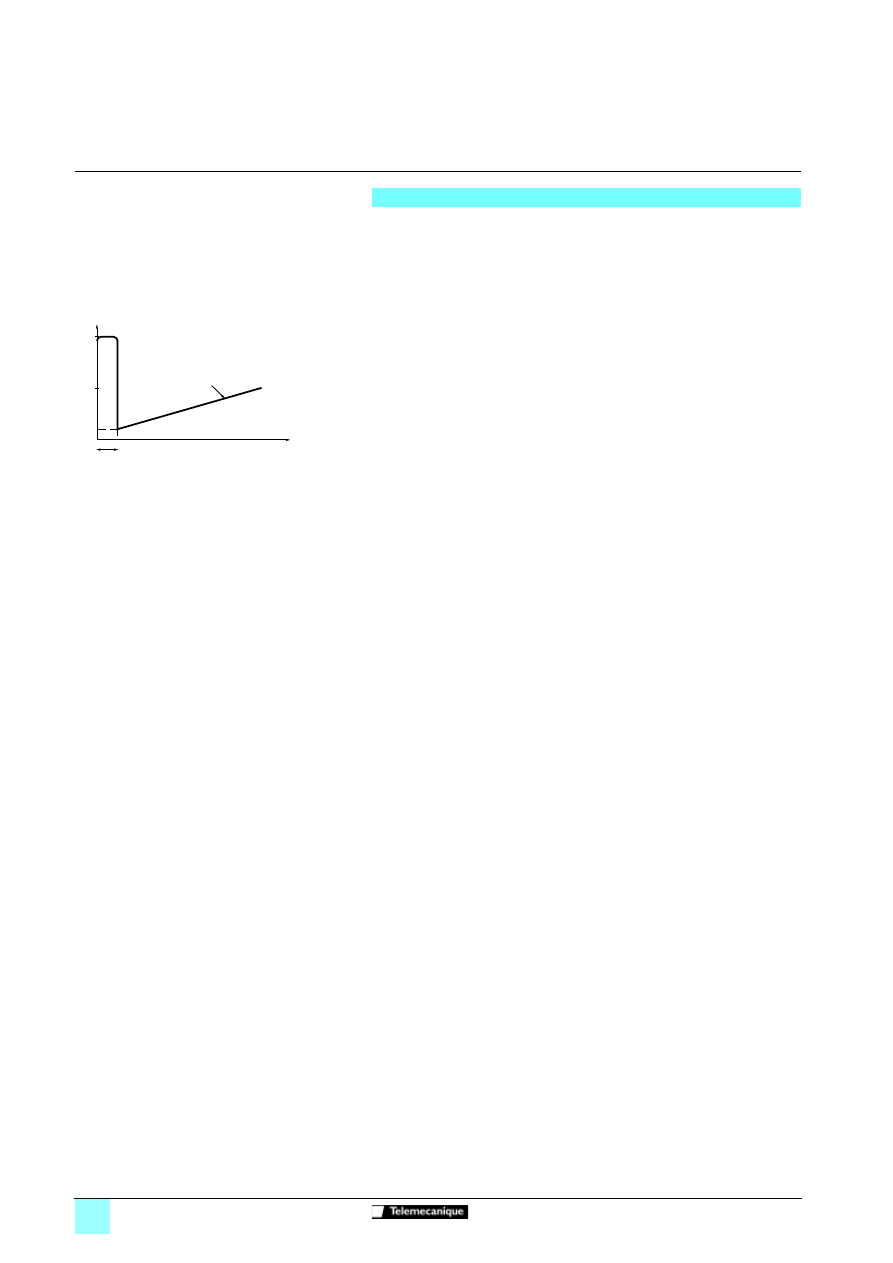
Voltage boost level
The function can be used to avoid any "starting" torque (phenomenon caused by
friction on stopping or by mechanical play). When a run command is sent, the starter
applies a fixed voltage to the motor for a limited period of time before starting. The
function can be disabled.
The voltage setting value varies between 50% and 100% of the nominal motor
voltage.
b
Connecting the starter to the motor delta terminal
ATS48
ppp
Q starters connected to motors with delta terminals can be wired in series
in the motor windings. This type of connection reduces the current in the starter by a
ratio of
3
, which enables a lower rating starter to be used. The nominal current and
limiting current settings as well as the current displayed during operation are on-line
values and are indicated on the motor. For this application, the braking or
decelerating stop functions are inactive. Only freewheel stopping is possible.
The adjustment range of the nominal motor current and the limiting current are
multiplied by
3
if the function is selected.
This function is not compatible with the following functions: motor phase loss
detection, motor preheating, cascade, decelerated stop and dynamic braking.
Use the scheme recommended on page 60524/4 for this type of configuration.
b
Test on low power motor
This function can be used to test a starter on a motor whose power is very much
lower that of the starter. It can be used for example to check the electrical wiring of
a device.
The function is automatically cancelled when the starter is switched off.
The next time the starter is switched on, the starter returns to its initial configuration.
b
Activation of the cascade function
This function can be used to start and decelerate several cascaded motors with a
single starter.
In order to gain maximum benefit from torque control, it is advisable to use motors
with powers between 0.5 and 1 times the power of the motor.
The wiring diagram for the cascaded motor function is shown on page 60524/6.
This function is not compatible with the following functions: motor preheating and
connection to the motor delta terminal.
b
Line frequency
The following frequencies can be selected for the function:
- 50 Hz. The frequency fault monitoring tolerance is ± 20%,
- 60 Hz. The frequency fault monitoring tolerance is ± 20%,
- automatic detection of the line frequency by the starter The frequency fault
monitoring tolerance is ± 6%.
v
50 Hz and 60 Hz are recommended if the power supply is provided by a generating
set, given their high tolerance.
b
Reset kWh or the operating time
Sets the value of the power in kW/h or the operating time value to 0. The calculation
of the values is updated once the reset command has been sent.
b
Return to factory settings
The function can be used to reset each setting to its initial value (starter factory
setting, see page 60526/2).
Advanced adjustment functions
50 %
Un
100 ms
100 %
Un
t
C
Cd
Rampe de couple
Application of a voltage boost equal to 100% of the
nominal motor voltage
Torque ramp
60526-EN_Ver1.12.fm/7
Schneider Electric
Functions
(continued)
Soft starters
0
Altistart 48 soft start - soft stop units
In order to access the 2nd motor adjustment functions, one logic input must be
assigned to the second set of motor parameters function. The adjustment functions
and ranges are identical for both sets of motor parameters.
The settings are as follows (see page 60526/3):
- nominal motor current,
- limiting current,
- acceleration ramp time,
- initial starting torque,
- deceleration ramp time,
- threshold for changing to freewheel stop mode at the end of deceleration,
- maximum torque limit.
The Altistart 48 is supplied with an RS 485 multidrop serial link with Modbus protocol
as standard. The serial link is configured in the Communication menu using:
v
The address of the starter, which can be set between 0 and 31.
v
The communication speed, which can be set at: 4800, 9600 or 19200 bps.
v
The format of the communication data. The following formats can be selected:
- 8 data bits, odd parity, 1 stop bit,
- 8 data bits, even parity, 1 stop bit,
- 8 data bits, no parity, 1 stop bit,
- 8 data bits, no parity, 2 stop bits.
v
The time-out, which can be set between 1 and 60 s.
The PowerSuite advanced dialogue solutions (see pages 60200/2 and 60200/3)
offer the following advantages:
v
Connection to the Altistart 48 and access to the adjustment, monitoring and control
functions.
v
Display of messages in plain text in 5 languages (English, French, German,
Spanish and Italian).
v
Preparation and saving of settings to hard disk.
v
Comparison and editing of settings using office automation tools.
v
Downloading of starter settings to the PC and uploading from the PC to the starter.
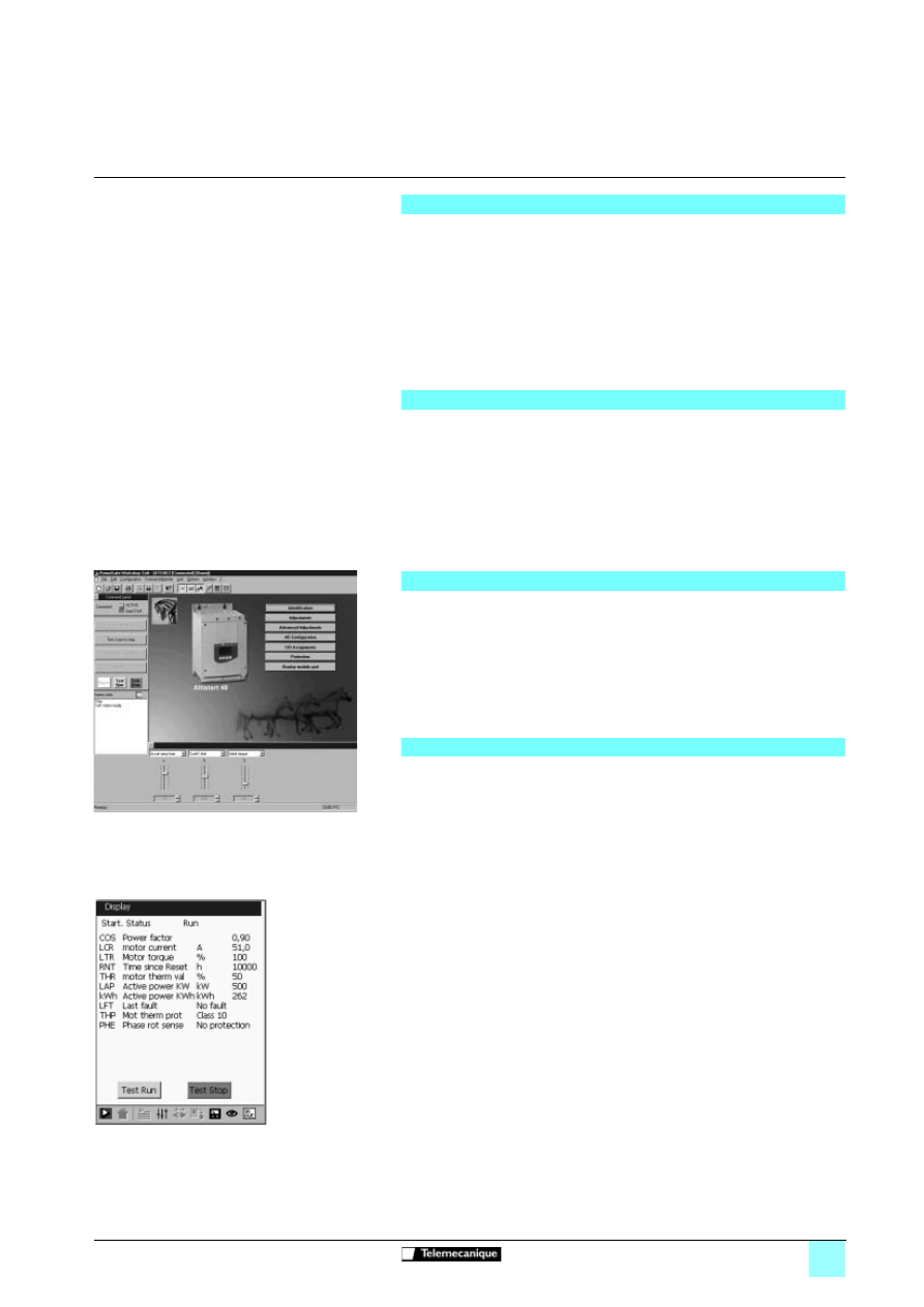
The monitoring functions provide the following information:
b
Cosine
ϕ
, displayed between 0.00 and 1.00.
b
Motor thermal state: 100% corresponds to the thermal state of the motor
consuming the permanently set nominal current.
b
Motor current: displayed in amperes between 0 and 999 A and in kilo amperes
between 1000 and 9999 A.
b
The operating time corresponding to the total number of starter operating hours
during heating, acceleration, steady state, deceleration, braking and continuous
bypass operation. It is displayed in hours between 0 and 999 hours and in kilo hours
between 1000 and 65536 hours.
b
The active power is displayed between 0 and 255%, where 100% corresponds to
the power at the set nominal current and at full voltage.
b
The motor torque is displayed between 0 and 255%, where 100% corresponds to
the nominal torque.
b
The active power consumed is displayed in kW. The line voltage value must be
configured. The accuracy of this setting will depend on the error between the voltage
configured and the actual voltage.
b
Power in kW/h displayed with PowerSuite.
b
The following starter states are shown in the display of the current state:
v
starter without run command and power not supplied,
v
starter without run command and power supplied,
v
acceleration/deceleration in progress,
v
steady state operation,
v
braking in progress,
v
starter in current limiting mode,
v
starting time delay not elapsed.
b
Last fault. Displays the last fault which occurred.
b
Phase rotation direction. Displays the direction of rotation (direct or indirect).
b
Terminal locking code
v
An access code can be used to protect access to the adjustment and configuration
parameters of the starter. Only the monitoring parameters will then be visible.
2
nd
motor adjustment functions
Communication functions
PowerSuite advanced dialogue solutions
Application monitoring functions
Displaying the commands and settings with
PowerSuite on PC
Monitoring the parameters with
PowerSuite on PPC
60526-EN_Ver1.12.fm/8
Schneider Electric
Functions
(continued)
Soft starters
0
Altistart 48 soft start - soft stop units
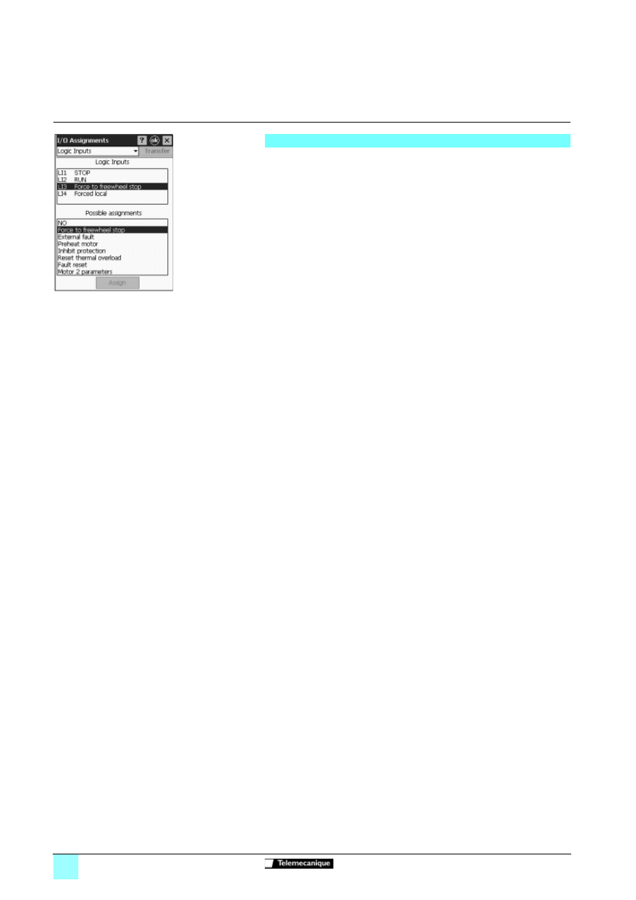
The starter has 4 logic inputs:
b
2 logic inputs (RUN and STOP) are reserved for run/stop commands which
can be sent in the form of stay-put contacts or as pulsed contacts.
v
2-wire control: Starting and stopping are controlled by a single logic input. State
1 of the logic input controls starting and state 0 controls stopping.
v
3-wire control: Starting and stopping are controlled by 2 separate logic inputs.
A stop is obtained on opening (state 0) the STOP input.
The pulse on the RUN input is stored until the stop input opens.
b
2 logic inputs (LI3 and LI4) can be configured with the following functions:
v
Freewheel stop: When combined with a braked stop or decelerated stop
command, activating the logic input will stop the motor in freewheel mode.
v
External fault: Enables the starter to detect an external user fault (level, pressure,
etc.). When the contact is open, the starter changes to fault mode.
v
Motor preheating: Used to prevent the motor from freezing or to prevent
temperature variations which may cause condensation. When the logic input is
activated, an adjustable current flows through the motor after a time delay which can
be set between 0 and 999 s. This current heats the motor without causing it to rotate.
This function is not compatible with the following functions: connection to the motor
delta terminal and cascading.
v
Force to local control mode: If a serial link is used, this function can be used to
change from line mode (control via serial link) to local mode (control via the terminal).
v
Inhibit all protection: Enables the forced operation of the starter in an emergency
by overriding the main faults (smoke extraction system for example).
Warning: This type of use invalidates the starter warranty.
v
Reset motor thermal fault: Enables the fault to be reset remotely.
v
Activation of the cascade function: In this case, the motor thermal protection is
disabled and relay R1 is configured as the fault isolation relay. Can be used to start
and decelerate several motors one after the other with a single starter (see
application diagram on pages 60524/6 and 60524/7).
v
Reset all faults: Enables all faults to be reset remotely.
v
Second set of motor parameters: Enables a second set of parameters to be
selected to start and decelerate two different motors with a single starter.
Logic input application functions
Assigning the logic inputs with
PowerSuite on PPC
60526-EN_Ver1.12.fm/9
Schneider Electric
Functions
(continued)
Soft starters
0
Altistart 48 soft start - soft stop units
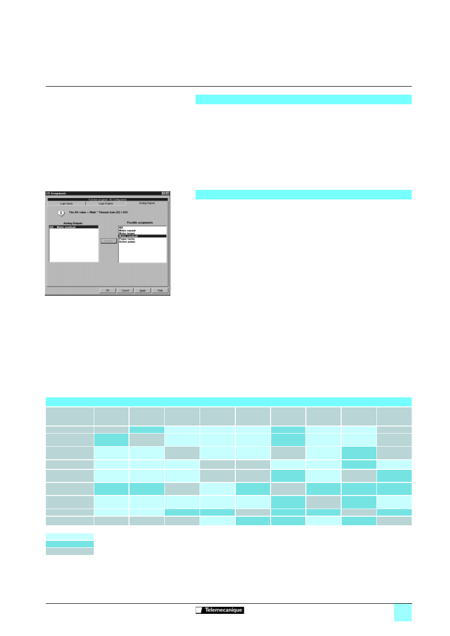
The starter has 2 logic outputs (LO1 and LO2) which, depending on their
configuration, can be used for remote indication of the following states or events:
b
Motor thermal alarm: Indicates that the motor thermal state has exceeded the
alarm threshold and can be used for example to avoid starting a motor if the thermal
reserve is insufficient.
b
Motor powered: Indicates that there may be current in the motor.
b
Motor overcurrent alarm: The motor current is higher than the threshold set.
b
Motor underload alarm: The motor torque is lower than the threshold set.
b
Motor PTC probe alarm: Indicates that the thermal state monitored by the PTC
motor probe has been exceeded.
b
Second set of motor parameters activated
The starter has 3 relays, 2 of which are configurable.
b
End of starting relay R2: Cannot be configured.
The end of starting relay controls the bypass contactor on the starter. It is activated
when the motor has completed the starting phase. It is deactivated when a stop
command is sent and in the event of a fault. The starter regains control when a
braking or deceleration command is sent.
b
Relay R1 application functions
Relay R1 can be configured as follows:
v
Fault relay: Relay R1 is activated when the starter is powered and there are no
faults. It is deactivated when a fault occurs and the motor switches to freewheel
mode.
v
Isolating relay: The contact of relay R1 closes when a run command is sent and
re-opens when a stop command is sent, at the end of deceleration on a decelerated
stop or in the event of a fault. The line contactor is deactivated and the motor is
isolated from the line supply (see application diagram page 60524/3).
b
Relay R3 application functions
Relay R3 is configured to indicate the same states or events as logic outputs LO1 or
LO2 (see above).
b
Analogue current output AO application functions
v
The analogue output AO provides an image of the following values:
motor current, motor torque, motor thermal state, cosine
ϕ
, active power.
v
The following settings are associated with the analogue output:
- the type of signal supplied: 0-20 mA or 4-20 mA,
- the scale setting of the signal. The function associates the maximum amplitude
of the analogue output (20 mA) with a percentage of the nominal value of the
parameter, which can be set between 50% and 500%.
Logic output application functions
Relay and analogue output application functions
Function compatibility table
Functions
Decelerating
stop
Dynamic
braking stop
Forced
freewheel
stop
Thermal
protection
Motor phase
loss detection
Connection to
the motor
delta terminal
Tests on low
power motor
Cascaded
motors
Motor
preheating
Decelerating stop
Dynamic braking
stop
Forced freewheel
stop
Thermal protection
(1)
Motor phase loss
detection
(1)
(1)
Connection to the
motor delta terminal
(1)
Tests on low power
motor
Cascaded motors
Motor preheating
(2)
(1)
Compatible functions
Incompatible functions
Not applicable
(1) Motor phase loss not detected.
(2) Thermal protection is not provided during motor preheating.
Assigning the analogue output with PowerSuite on PC
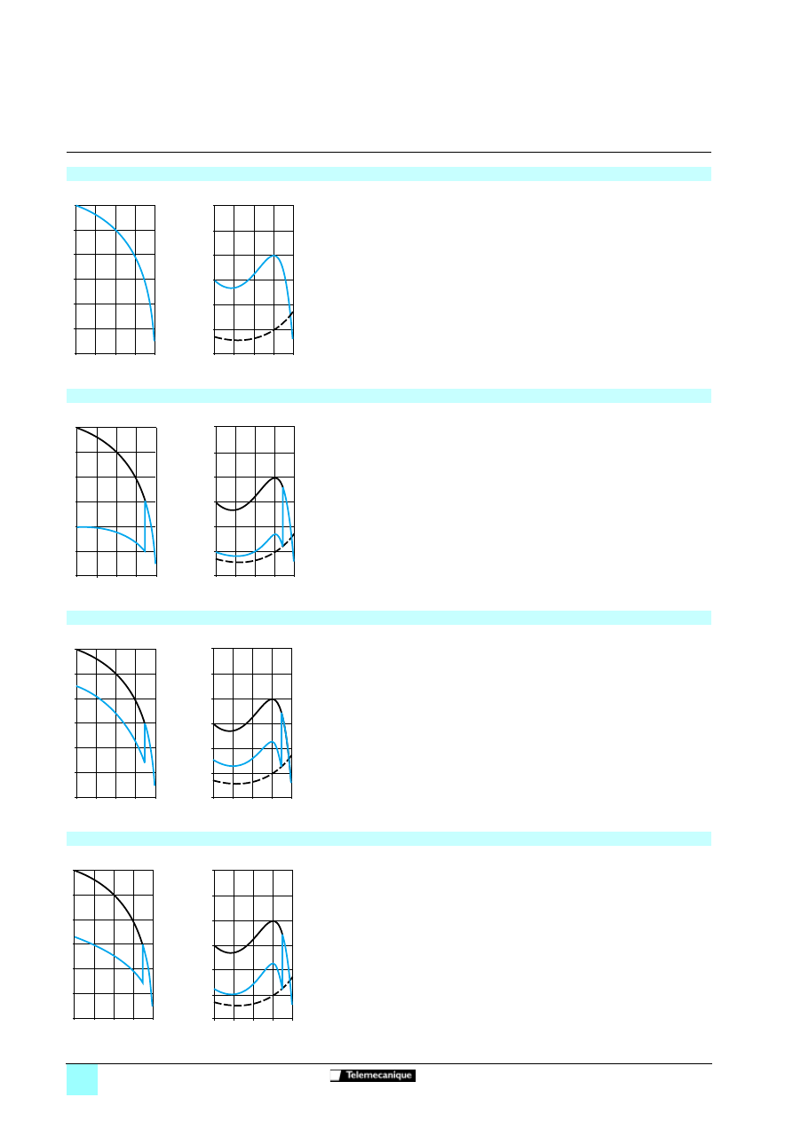
60527-EN_Ver1.11.fm/2
Schneider Electric
Curves
Soft starters
0
Conventional starting
of three-phase asynchronous motors
Direct starting
b
Starting current: 4 to 8 times the nominal current.
b
Starting torque: 0.5 to 1.5 times the nominal torque.
b
Characteristics:
v
motor with 3 terminals, low and medium power,
v
on-load starting,
v
high current peak and voltage drop,
v
simple device,
v
sudden starting for the mechanism.
b
No parameter adjustment.
"Star-delta" starting
b
Starting current: 1.8 to 2.6 times the nominal current.
b
Starting torque: 0.5 times the nominal torque.
b
Characteristics:
v
motor with 6 terminals,
v
no-load or low resistive torque starting,
v
high current peaks and torque when changing to "star-delta" mode,
v
a device requiring maintenance,
v
subject to mechanical stress when starting.
b
No parameter adjustment.
Rheostatic stator starting
b
Starting current: 4.5 times the nominal current.
b
Starting torque: 0.5 to 0.75 times the nominal torque.
b
Characteristics:
v
motor with 3 terminals, high power,
v
starting with increasing resistive torque,
v
high current peak,
v
a large, bulky device requiring maintenance,
v
subject to mechanical stress when starting.
b
No parameter adjustment.
Auto transformer starting
b
Starting current: 1.7 to 4 times the nominal current.
b
Starting torque: 0.4 to 0.85 times the nominal torque.
b
Characteristics:
v
motor with 3 terminals, high power,
v
large voltage drop and current peak when connected at full voltage,
v
a complex, bulky device requiring maintenance,
v
subject to mechanical stress when starting.
b
No parameter adjustment.
6
5
4
3
2
1
0
0
0,25 0,5
0,75
1
N/Ns
I/In
2,5
2
3
1,5
1
0,5
0
0
0,25 0,5
0,75
1
N/Ns
C/Cn
Cr
Starting current
Starting torque
6
5
4
3
2
1
0
0
0,25 0,5
0,75
1
N/Ns
I/In
2,5
2
3
1,5
1
0,5
0
0
0,25
0,5 0,75
1
N/Ns
C/Cn
Cr
Starting current
Starting torque
6
5
4
3
2
1
0
0
0,25 0,5
0,75
1
N/Ns
I/In
2,5
3
2
1,5
1
0,5
0
0
0,25
0,5 0,75
1
N/Ns
C/Cn
Cr
Starting current
Starting torque
6
5
4
3
2
1
0
0
0,25 0,5 0,75
1
N/Ns
I/In
2,5
2
3
1,5
1
0,5
0
0
0,25 0,5
0,75
1
N/Ns
C/Cn
Cr
Starting current
Starting torque
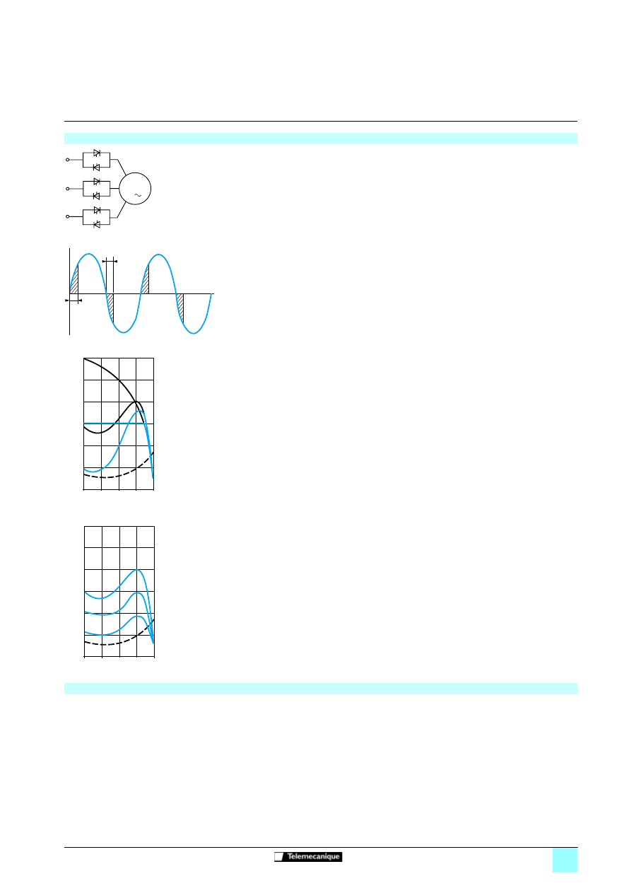
60527-EN_Ver1.11.fm/3
Schneider Electric
Curves
(continued)
Soft starters
0
Progressive starting
of three-phase asynchronous motors
Conventional electronic starting with variable voltage and current limiting
b
A controller with 6 thyristors connected head to tail in each line phase is used to power the
three-phase asynchronous motor by gradually increasing the voltage on start-up.
v
Depending on the firing time and angle of the thyristors, it can be used to supply a voltage
which will gradually increase at a fixed frequency.
v
The gradual increase in the output voltage can either be controlled by the acceleration ramp,
or by the value of the limiting current, or linked to both parameters.
b
Figure 1 shows the behaviour of the torque in relation to the starting current.
Limiting the starting current Is to a preset value Is1 will reduce the starting torque Ts1 to a value
which is almost equal to the ratio of the square of currents Is and Is1.
Example
On a motor with the following characteristics: Ts = 2 Tn for Is = 6In, current limiting at Is1= 3 In
or 0.5 Is results in a starting torque: Ts1 = Ts x (0.5)2 = 2 Tn x 0.25 = 0.5 Tn.
b
Figure 2 shows the torque/speed characteristic of a squirrel cage motor in relation to the
supply voltage.
The torque varies like the square of the voltage at a fixed frequency. The gradual increase in the
voltage prevents the instantaneous current peak on power-up.
Advantages of starting with the Altistart 48
b
Conventional electronic starting
To rectify problems caused by:
- mechanical stress when starting,
- hydraulic transients during acceleration and deceleration in pump applications.
Conventional electronic starting requires the use of several current limits or the switching of
several voltage ramps.
The settings become complicated and must be modified every time the load changes.
b
Starting with the Altistart 48
The Altistart 48 torque control enables starting without mechanical stress and the smooth control
of hydraulic transients with a single acceleration ramp.
The settings are simple and effective, whatever the load.
3
M
α
α
Schematic diagram
Firing angle
0
0
0,25
0,5
0,75
1
N/Ns
Cr
Cd1
Cd
Id1
Id
Figure 1
Figure 2
0
0
0,25
0,5
0,75
1
N/Ns
Cr
U
0,85 U
0,6 U
C
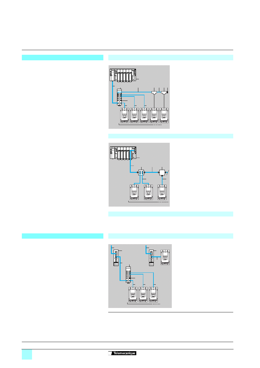
60528-EN_Ver2.0.fm/2
Schneider Electric
Presentation
Soft starters
1
Altistart 48 soft start - soft stop units
Communication options
Modbus communication bus
Connections via splitter blocks and RJ45 type connectors
The Altistart 48 is connected directly to the Modbus bus
via its RJ45 type connector port.
This port supports the RS 458 (2-wire) standard
and the Modbus RTU protocol.
The communication function provides access to the
configuration, adjustment, control and signalling
functions of the starter.
1
PLC (1)
2
Modbus cable depending on the type
of controller or PLC
3
Modbus splitter block LU9 GC3
4
Modbus drop cable VW3 A8 306 R
pp
5
Line terminators
VW3 A8 306 RC
6
Modbus T-junction box
VW3 A8 306 TF
pp
(with cable)
Connections via junction boxes
1
PLC (1)
2
Modbus cable depending on the type
of controller or PLC
3
Modbus cable TSX CSA
p
00
4
Junction box TSX SCA 50
5
Subscriber sockets TSX SCA 62
6
Modbus drop cable
VW3 A8 306
7
Modbus drop cable
VW3 A8 306 D30
Connections via screw terminals
In this case, use a Modbus drop cable VW3 A8 306 D30 and line terminators
VW3 A8 306 DRC.
Other communication buses
Connection via modules
The Altistart 48 can also be connected to Ethernet,
Fipio, Profibus DP and DeviceNet networks via a
module (bridge or gateway).
Communication on the network is used for:
b
controlling
b
monitoring and
b
configuring the Modbus products connected to the
network
1
To network
2
Communication modules
3
Cables VW3 A8 306 R
pp
,
VW3 P07 306 R10 or
VW3 A8 306 D30
4
Modbus splitter block LU9 GC3
5
Modbus drop cable VW3 A8 306 R
pp
6
Line terminator
VW3 A8 306 RC
(1) Please consult our "Premium Automation Platform" and "Micro Automation Platform"
specialist catalogues.
5
4
4
4
1
2
4
3
4
6
6 5
ATS 48
3
2
6
1
7
4
5
ATS 48
2
1
6
ATS 48
5
5
5
3
2
1
4
ATS 48
3
References:
page 60528/3
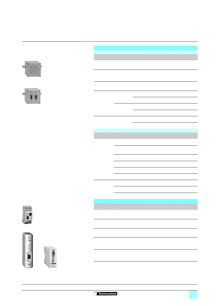
60528-EN_Ver2.0.fm/3
Schneider Electric
References
Soft starters
1
Altistart 48 soft start - soft stop units
Communication options
Modbus communication bus
Connection accessories
Description
Reference
Weight
kg
Junction box
3 screw terminals, RC line terminator
To be connected using cable VW3 A8 306 D30
TSX SCA 50
0.520
Subscriber sockets
2 x female 15-way SUB-D connectors
and 2 screw terminals, RC line terminator
To be connected using cable VW3 A8 306
TSX SCA 62
0.570
Modbus splitter block
8 RJ45 type connectors and 1 screw terminal
LU9 GC3
0.500
Line
terminators
(1)
For RJ45
connector
R = 120
Ω,
C = 1 nF
VW3 A8 306 RC
0.200
R = 150
Ω
VW3 A8 306 R
0.200
For screw
terminals
R = 120
Ω,
C = 1 nF
VW3 A8 306 DRC
0.200
R = 150
Ω
VW3 A8 306 DR
0.200
Modbus T-junction boxes
With integrated cable (0.3 m) VW3 A8 306 TF03
–
With integrated cable (1 m)
VW3 A8 306 TF10
–
Connecting cables
Description
Length
m
Connectors
Reference
Weight
kg
Cables for
Modbus bus
3
1 RJ45 connector
and one end stripped
VW3 A8 306 D30
0.150
3
1 RJ45 connector and 1male
15-way SUB-D connector for
TSX SCA 62
VW3 A8 306
0.150
0.3
2 RJ45 connectors
VW3 A8 306 R03
0.050
1
2 RJ45 connectors
VW3 A8 306 R10
0.050
3
2 RJ45 connectors
VW3 A8 306 R30
0.150
1
2 RJ45 connectors
VW3 P07 306 R10
0.050
RS 485 double
shielded twisted
pair cables
100
Supplied without connector
TSX CSA 100
–
200
Supplied without connector
TSX CSA 200
–
500
Supplied without connector
TSX CSA 500
–
Other communication buses
Description
Cables
to be connected
Reference
Weight
kg
Ethernet/Modbus bridge
with 1 x Ethernet 10baseT port
(RJ45 type)
VW3 A8 306 D30
174 CEV 300 10 (2)
0.500
Fipio/Modbus gateway
(3)
VW3 A8 306 R
pp
LUF P1
0.240
DeviceNet/Modbus gateway
(3)
VW3 A8 306 R
pp
LUF P9
0.240
Profibus DP/Modbus gateway
Parameters set using standard
Profibus DP configurator,
Hilscher Sycon type (4)
VW3 P07 306 R10
LA9 P307
0.240
Profibus DP/Modbus gateway
Parameters set using
ABC Configurator software (3)
VW3 A8 306 R
pp
LUF P7
0.240
(1) Sold in lots of 2.
(2) Please consult our "Premium Automation Platform" specialist catalogue.
(3) See pages 24618/2 and 24618/3.
(4) See pages 24619/2 and 24619/3.
TSX SCA 50
TSX SCA 62
174 CEV 300 10
LUF P1
LA9 P307
Presentation:
page 60528/2

60529-EN_Ver1.12.fm/2
Schneider Electric
Selection guide
Soft starters
0
Altistart 48 soft start - soft stop units
The Altistart 48 must be selected on the basis of 3 main criteria:
b
Two line power supply voltage ranges are available for selection:
v
three-phase a.c. voltage: 230 - 415 V,
v
three-phase a.c. voltage: 208 - 690 V.
b
The power and the nominal current indicated on the motor name plate.
b
The type of application and the operating cycle.
To simplify selection, the applications are categorised into 2 types:
v
standard applications,
v
severe applications.
Standard or severe applications define the limiting values of the current and the cycle
for motor duties S1 and S4.
In standard applications, the Altistart 48 is designed to provide:
b
Starting at 4 In for 23 seconds or at 3 In for 46 seconds from a cold state
(corresponding to motor duty S1).
b
Starting at 3 In for 23 seconds or at 4 In for 12 seconds
with a load factor of 50% and 10 starts per hour or a an equivalent thermal cycle
(corresponding to motor duty S4)
The motor thermal protection must conform to protection class 10
(see page 60526/4).
Example: centrifugal pump.
In severe applications, the Altistart 48 is designed to provide:
b
Starting at 4 In for 48 seconds or at 3 In for 90 seconds from a cold state
(corresponding to S1 motor duty).
b
Starting at 4 In for 25 seconds with a load factor of 50% and 5 starts per hour or a
an equivalent thermal cycle (corresponding to S4 motor duty)
The motor thermal protection must conform to protection class 20
(see page 60526/4).
Example: grinder.
S1 motor duty corresponds to starting followed by operation at constant load
enabling the thermal equilibrium to be reached.
S4 motor duty corresponds to a cycle comprising starting,
operation at constant load and an idle period.
This cycle is characterised by a load factor of 50%.
Once the appropriate application has been selected from the following page, select
the starter from pages 60522/2 to 60522/5 according to the supply voltage
and the motor power.
Caution:
If the Altistart 48 is installed inside an enclosure, observe the mounting and derating
recommendations (see page 60523/5).
Selection criteria for an Altistart 48 soft start - soft stop unit
Standard application
Severe application
Motor duties
Selecting the starter

60529-EN_Ver1.12.fm/3
Schneider Electric
Selection criteria
(continued)
Soft starters
0
Altistart 48 soft start - soft stop units
Application areas
Depending on the type of machine, the applications are categorized as standard or severe based on the starting characteristics, which are
given as examples only, in the table below.
Type of machine
Application
Functions performed by the Altistart 48
Starting current
(% In)
Starting time
(s)
Centrifugal pump
Standard
Deceleration (reduction in pressure surges)
Protection against underloads or inversion
of the phase rotation direction
300
5 to 15
Piston pump
Standard
Control of running dry and direction of rotation
of the pump
350
5 to 10
Fan
Standard
Severe if > 30 s
Detection of overloads caused by clogging
or underloads (motor fan
transmission broken)
Braking torque on stopping
300
10 to 40
Cold compressor
Standard
Protection, even for special motors
300
5 to 10
Screw compressor
Standard
Protection against inversion of direction of
phase rotation
Contact for automatic draining on stopping
300
3 to 20
Centrifugal compressor
Standard
Severe if > 30 s
Protection against inversion of direction of
phase rotation
Contact for automatic emptying on stopping
350
10 to 40
Piston compressor
Standard
Protection against inversion of direction of
phase rotation
Contact for automatic emptying on stopping
350
5 to 10
Conveyor, transporter
Standard
Overload control for detecting faults
or underload control for detecting breaks
300
3 to 10
Lifting screw
Standard
Overload control for detecting hard spots
or underload control for detecting breaks
300
3 to 10
Drag lift
Standard
Overload control for detecting jamming
or underload control for detecting breaks
400
2 to 10
Lift
Standard
Overload control for detecting jamming
or underload control for detecting breaks
Constant starting with variable load
350
5 to 10
Circular saw, band saw
Standard
Severe if > 30 s
Braking for fast stop
300
10 to 60
Pulper, butchery knife
Severe
Torque control on starting
400
3 to 10
Agitator
Standard
The current display indicates the density
of the product
350
5 to 20
Mixer
Standard
The current display indicates the density
of the product
350
5 to 10
Grinder
Severe
Braking to limit vibrations during stopping, overload
control to detect jamming
450
5 to 60
Crusher
Severe
Braking to limit vibrations during stopping, overload
control to detect jamming
400
10 to 40
Refiner
Standard
Torque control on starting and stopping
300
5 to 30
Press
Severe
Braking to increase the number of cycles
400
20 to 60
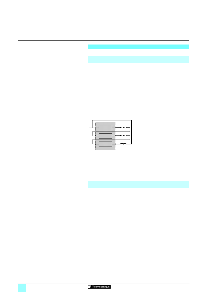
60529-EN_Ver1.12.fm/4
Schneider Electric
Selection criteria
(continued)
Soft starters
0
Altistart 48 soft start - soft stop units
Other criteria can influence the selection of the Altistart 48:
In addition to the most frequently encountered wiring layouts, where the starter is
installed in the line supply of the motor and the motor is connected in star or delta
configuration, the Altistart 48 ATS48•••Q can be wired to the motor delta terminal in
series with each winding (see the application diagram below). The starter current is
lower than the line current absorbed by the motor by a ratio of
3
. This type of
installation enables a starter with a lower rating to be used.
Example: For a 400 V/110 kW motor with a line current of 195 A (nominal current for
the delta connection), the current in each winding is equal to 195/
3
, i.e. 114 A.
Select the starter rating with a maximum permanent nominal current just above this
current, i.e. 140A (ATS48C14Q for a standard application).
To avoid making this calculation, simply use the table on page 60522/3.
This type of installation only permits freewheel stopping and is not compatible with
the cascade and preheating functions.
Note: The nominal current and limiting current settings as well as the current
displayed during operation are on-line values (so do not have to be calculated by the
user).
Caution: For this type of installation, observe the wiring scheme and the associated
recommendations on page 60524/4.
The starter can be bypassed by a contactor at the end of starting (to limit the heat
dissipated by the starter). The bypass contactor is controlled by the starter and the
current measurements and protective mechanisms remain active when the starter is
bypassed.
The starter is selected on the basis of the 3 main criteria and one of the following
criteria:
b
If the starter is bypassed at the end of starting, the motor is always started from
cold state and the starter can be oversized by one rating.
Example: Select an ATS 48D17Q for an 11 kW motor in a standard 400 V application.
b
If the starter must be able to operate without the bypass contactor at the end of
starting, it does not have to be derated.
Example: Select an ATS 48D17Q for a 7.5 kW motor in a standard 400 V application.
Special uses
Starter wired to the motor delta terminal
(see the recommended application diagram on page 60524/4)
Starter bypassed by a contactor
(see the recommended application diagram on page 60524/3)
Starter wired in series with the motor
windings
ATS48•••Q
motor

60529-EN_Ver1.12.fm/5
Schneider Electric
Selection criteria
(continued)
Soft starters
0
Altistart 48 soft start - soft stop units
Motors may be connected in parallel provided that the power limit of the starter is not
exceeded (the sum of the motor currents must not exceed the nominal current of the
starter selected depending on the type of application). Provide thermal protection for
each motor.
The Altistart 48 can operate with a bypassed rotor resistance motor or with a
resistance lug. The starting torque is modified in accordance with the rotor
resistance. If necessary, maintain a low resistance in order to obtain the required
torque to overcome the resistive torque on starting.
A bypassed brush motor has a very low starting torque. A high stator current is
required to obtain the sufficient starting torque.
Oversize the starter in order that the value of the limiting current is 7 times that of the
nominal current.
Note: Ensure that the starting torque of the motor, equal to 7 times the nominal
current, is greater than the resistive torque.
Note: The Altistart 48 torque control enables excellent soft starting despite the
limiting current being 7 times the nominal current required to start the motor.
The Altistart 48 can operate with a 2-speed motor. A motor demagnetisation period
must elapse before changing from low speed to high speed in order to avoid
antiphases between the line supply and the motor, which would generate very high
currents.
Select the starter using the 3 main criteria.
Very long motor cables cause voltage drops due to the resistance of the cable. If the
voltage drop is significant, it could affect the current consumption and the torque
available. This must therefore be taken into account when selecting the motor and
the starter.
If several starters are installed on the same line supply, line chokes should be
installed between the transformer and the starter (see page 60528/3).
Caution: Do not use the Altistart 48 upstream of loads other than motors (for
example transformers and resistors are forbidden).
Do not connect power factor correction capacitors to the terminals of a motor
controlled by an Altistart 48.
Special uses
(continued)
Motors in parallel
Brush motor
Dahlander motor and 2-speed motor
Very long cable
Starters in parallel on the same line supply
Recommendations for use
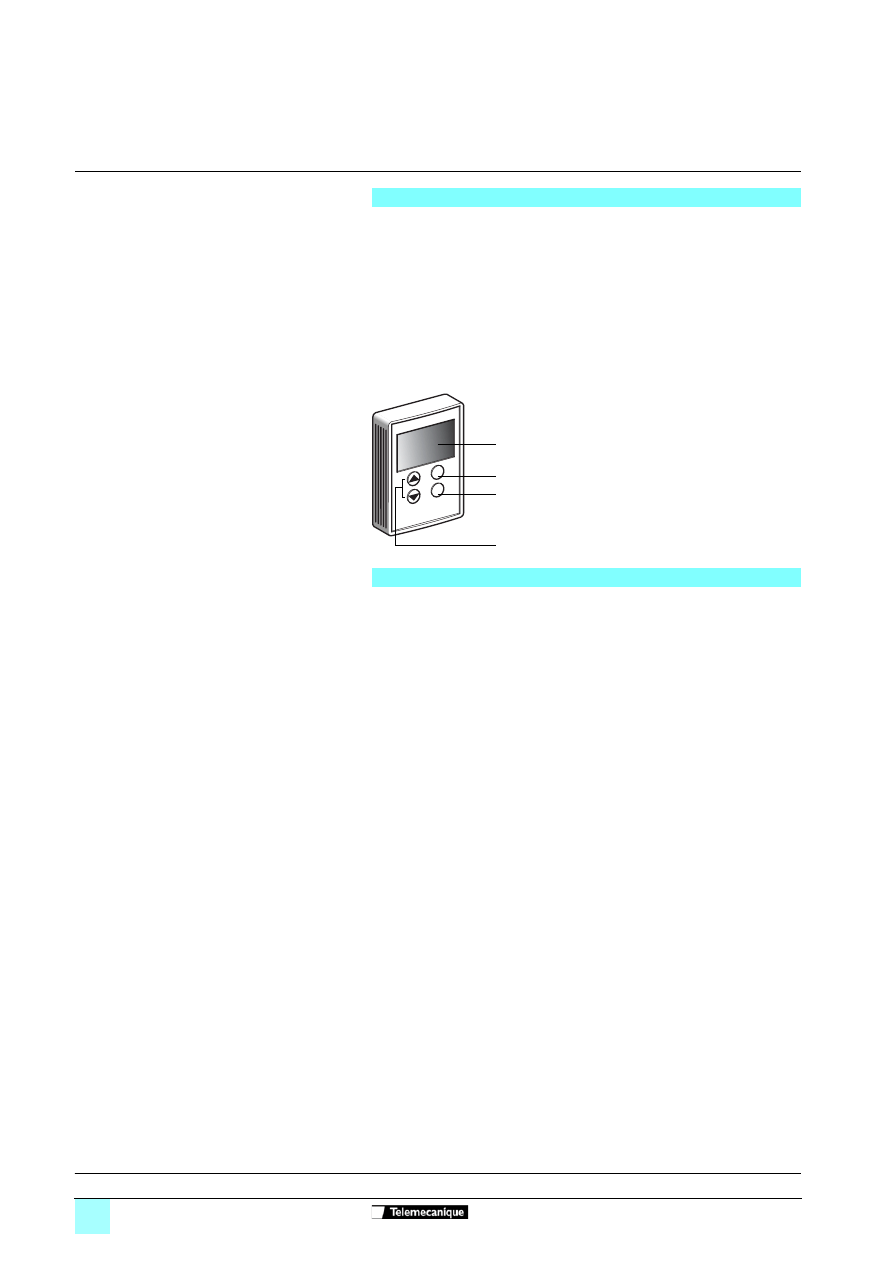
60530-EN_Ver1.0.fm/2
Schneider Electric
Presentation
Soft starters
1
Altistart 48 soft start - soft stop units
Options: Remote terminal, line chokes
The terminal can be mounted on the door of a wall-fixing or floor-standing enclosure.
It has the same signalling display and configuration buttons as the terminal
integrated in the starter. A switch to lock access to the menu is located at the rear of
the terminal.
The option comprises:
- the remote terminal
- a mounting kit containing a cover, screws and an IP 54 seal on the front panel
- a 3 m connecting cable with a 9-way SUB-D connector for connecting to the
terminal and an RJ45 connector for connecting to the Altistart 48
The use of line chokes is recommended in particular when installing several
electronic starters on the same line supply. The values of the chokes are defined for
a voltage drop between 3% and 5% of the nominal line voltage.
Install the line choke between the line contactor and the starter.
Remote terminal
1
Information is displayed in the form of
codes or values in three "7-segment"
displays
2
Buttons for scrolling through the menus
or modifying values
3
"ESC": Button for exiting the menus
(cannot be used for validation
purposes)
4
"ENT": Validation button for entering a
menu or confirming the new value
selected
ESC
ENT
1
3
4
2
Line chokes
References:
page 60530/3
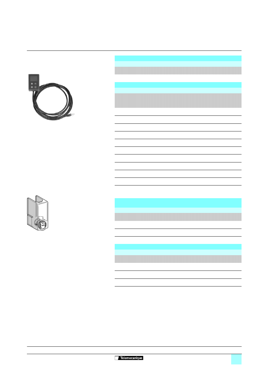
60530-EN_Ver1.0.fm/3
Schneider Electric
References
Soft starters
1
Altistart 48 soft start - soft stop units
Options: Remote terminal, line chokes,
protective covers, documentation
Note: Line chokes with IP 00 degree of protection must be fitted with a protective bar to protect
personnel against electrical contact.
Remote terminal
Reference
Description
Reference
Weight
kg
Remote terminal
VW3 G48101
0.200
Line chokes
References
For starters
Value
of the
choke
mH
Nominal
current
A
Degree of
protection
Reference
Weight
kg
ATS 48D17
p
1.7
15
IP 20
VZ1 L015UM17T
2.100
ATS 48D22
p
0.8
30
IP 20
VZ1 L030U800T
4.100
ATS 48D32
p
and 48D38
p
0.6
40
IP 20
VZ1 L040U600T
5.100
ATS 48D47
p
and 48D62
p
0.35
70
IP 20
VZ1 L070U350T
8.000
ATS 48D75
p
to 48C14
p
0.17
150
IP 00
VZ1 L150U170T
14.900
ATS 48C17
p
to 48C25
p
0.1
250
IP 00
VZ1 L250U100T
24.300
ATS 48C32
p
0.075
325
IP 00
VZ1 L325U075T
28.900
ATS 48C41
p
and 48C48
p
0.045
530
IP 00
VZ1 L530U045T
37.000
ATS 48C59
p
to 48M10
p
0.024
1025
IP 00
VZ1 LM10U024T
66.000
ATS 48M12
p
0.016
1435
IP 00
VZ1 LM14U016T
80.000
VW3 G48101
106770
Protective covers for power terminals
To be used with tags closed
References
For starters
Number of covers
per set
Reference
Weight
kg
ATS 48C14
p
and ATS 48C17
p
6 (1)
LA9 F702
0.250
ATS 48C21
p
, ATS 48C25
p
and ATS 48C32
p
6 (1)
LA9 F703
0.250
(1) The starters have 9 unprotected power terminals.
8
13095
LA9 F702
Documentation
References
Description
Format
Reference
Weight
kg
Altistart 48 user's manual
A5
VVD ED 301066
0.150
Modbus user's manual
A5
VVD ED 302023
0.150
International technical manual
(ITM) (2)
CD-ROM
DCI CD 398111
0.150
(2) Library containing:
- manuals and quick reference guides for starters and speed drives
- user's manuals for communication gateways
Presentation:
page 60530/2
Document Outline
- Altistart 48
- Presentation
- Characteristics
- References
- Dimensions
- Mounting
- Functions
- Curves
- Presentation
- References
- Selection guide
- Selection criteria
Wyszukiwarka
Podobne podstrony:
więcej podobnych podstron