Design, Fabrication and Analysis of Bipedal
Walking Robot
Vaidyanathan.V.T
1
and Sivaramakrishnan.R
2
1, 2
Mechatronics,
Department of Production Technology,
Madras Institute of Technology, Anna University,
INDIA
1
raj.vaidhya@gmail.com &
2
srk@mitindia.edu
Abstract— This paper describes the design, fabrication
and analysis of Bipedal walking robot. The main objective of
the project is to study about the theories and the practical
challenges involved in making it. The Bipedal walking robot
is designed with minimal number of actuators (RC
Servomotor) and it is controlled by low cost 8051 micro
controller. The robot uses simple U-shaped servomotor
brackets for joint formation. It walks like a human by
balancing the Centre of Mass.
Key words— Centre of Mass (C.O.M), Degrees of
Freedom (D.O.F), RC servomotor
I. INTRODUCTION
With advances in science and technology, the interest to study
the human walking has developed the demand for building the
Bipedal robots. The development of Bipedal walking robot
involves research in heterogeneous areas. This Paper describes
the first attempt in building the Bipedal walking robot.
MIT BIPED:
Design of Bipedal robot involves equal amount of
mechanical and electronics considerations. There are many
factors which are to be considered are cost, actuator, size,
weight and controlling of actuators. All these factors have
been considered and designed. The robot has six degrees of
freedom, with three degrees of freedom per leg. Each leg has
Hip, Knee and Ankle. The hip and knee Joints are actuated in
vertical plane (Pitch) and the ankle joints are actuated in
horizontal plane (Roll).
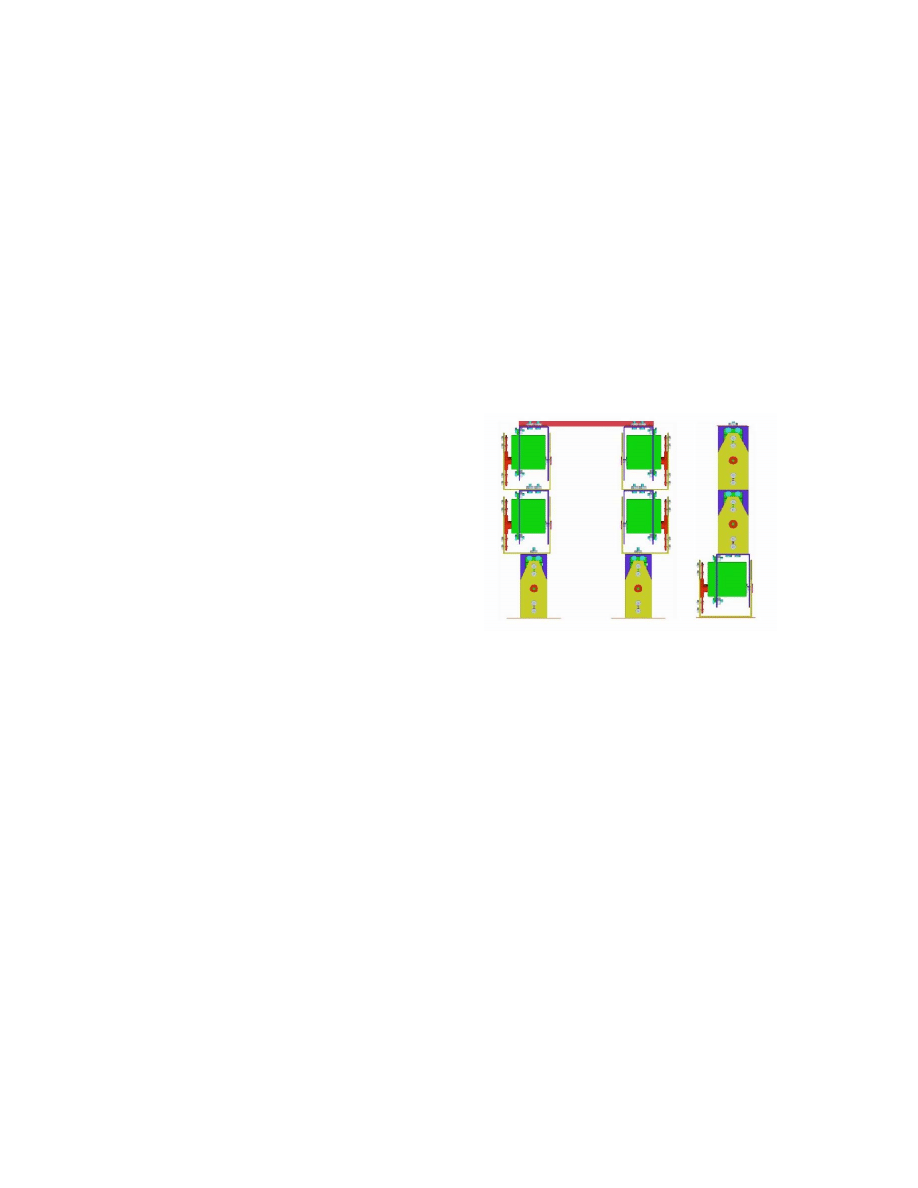
Figure 1 shows the Bipedal Robot model. The Biped is
capable of demonstrating walking without any torso
arrangement (or) weight shifting mechanism.
II. M
ECHANICAL
D
ESIGN
O
F
B
IPEDAL ROBOT
The Mechanical design forms the basis for developing this
type of walking robots. The mechanical design is divided into
four phases:
A: Determining the Mechanical constraints.
B: Conceptual Design
C: Building the Prototype model
D: Specification and Fabrication of the model.
Figure 1 Bipedal Robot
A Determining the Mechanical Constraints
There are various design considerations when designing a
Bipedal robot. Among them, the major factors that have to be
considered are Robot’s size selection, Degrees of freedom
(D.O.F) selection, Link Design, Stability and Foot Pad design.
1) Robot Size Selection:
Robot size plays a major role. Based on this the Cost of
the Project, Materials required for fabrication and the no of
Actuators required can be determined. In this project
miniature size of the robot is preferred so a height of 300mm
is decided which includes mounting of the control circuits, but
the actual size of the robot is 230mm without controlling
circuits.
2) Degrees of Freedom (D.O.F):
Human leg has got Six Degrees of freedom (Hip – 3
D.O.F, Knee – 1 D.O.F, Ankle – 2 D.O.F), but implementing
all the Six D.O.F is difficult due to increase in cost of the
project and controlling of the actuators which become
complex, so in this project reduced degrees of freedom is
aimed so 3 D.O.F per leg has been finalized.
3) Link Design:
In this project U-shaped bracket like
arrangement is used for joints formation. The bracket consists
of two parts namely Servomotor bracket A and B (figure2).
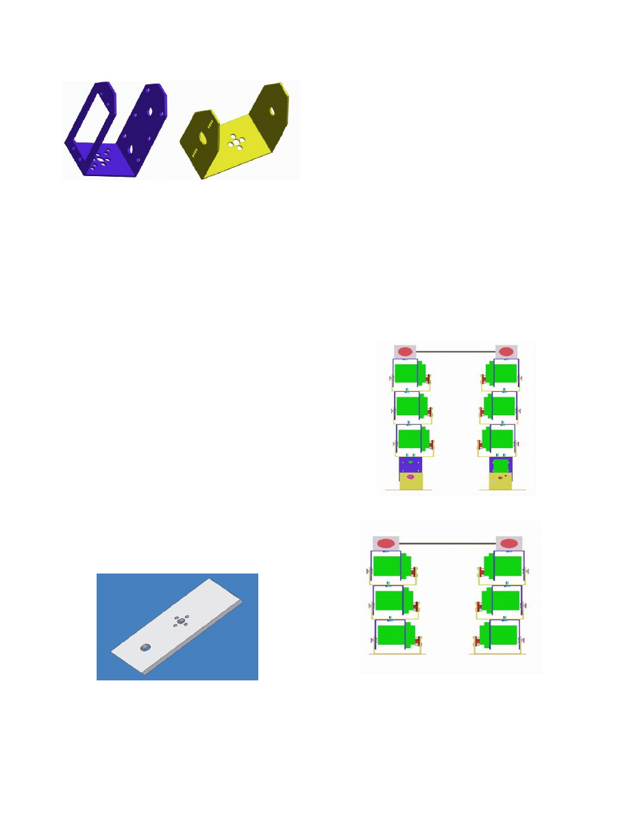
A
B
Figure 2 Brackets A and B
Servomotor will be fixed in the bracket A and the bracket
B is used to transmit the output of the servomotor. Bracket B
and servomotor are coupled using servomotor horn. By using
the brackets there is a greater flexibility and individual joint
can be actuated without disturbing the other joints. The
Servomotor brackets are designed in accordance with the
motor size. Dimensions of Bracket A - 65x33x32mm, Bracket
B – 65x58x32mm
4) Stability:
With Biped mechanism, only two points will be in
contact with the ground surface. In order to achieve effective
balance, actuator will be made to rotate in sequence and the
robot structure will try to balance. If the balancing is not
proper, in order to maintain the Centre of Mass, dead weight
would be placed in inverted pendulum configuration with 1
D.O.F. This dead weight will be shifted from one side to the
other according to the balance requirement. But in this project
no such configuration is used.
5) Foot Pad Design:
The stability of the robot is determined by the foot pad.
Generally there is a concept that over sized and heavy foot
pad will have more stability due to more contact area. But
there is a disadvantage in using the oversized and heavy foot
pad, because the torque requirement of the motor is more and
lifting the leg against the gravity becomes difficult. By
considering this disadvantage an optimal sized foot pad was
used. Dimensions of the foot pad are 85x70mm and is shown
in figure 3
Figure 3 Foot Pad
B. Conceptual Design
Initially the Bipedal robot was conceived with ten degrees
of freedom with four degrees of freedom per leg and two
Passive degrees of freedom (figure 4). Due to constraints
faced in controlling greater number degrees of freedom, the
Bipedal model is redesigned with eight Degrees of freedom
with three degrees of freedom per leg and two passive degrees
of freedom. In this design all the joints are actuated in Pitch
orientation. On further analysis of the model, drawback that
all the joints are actuated in Pitch orientation was brought into
light. Furthermore passive degrees of freedom were always
compensated.
Finally, a new design was arrived with the knowledge
gathered from developing previous Bipedal models. The new
design has got Six degrees of freedom with three degrees of
freedom per leg (figure 1). Hip and Knee are actuated in Pitch
orientation and Ankle joint is actuated in Roll orientation.
This design has more stability with equal weight distribution
on both the legs. Passive Degrees of Freedom considered in
the previous models have been removed and both legs are
connected by a link.
Optimal distance was maintained between the legs to ensure
that legs don’t hit each other while walking. In this model the
ankle joint is mainly actuated in Roll orientation in order to
shift the centre of mass and also helpful for the other leg to lift
up easily. All the 3D models are developed using Pro-
Engineer wild fire version2 software.
Figure 4 First Design
Figure 5 Second Design
C. Proto type
After developing the Biped model in software, a prototype
model has been made using cardboard in order to see how the
joints will be formed. It is shown in the figure 6
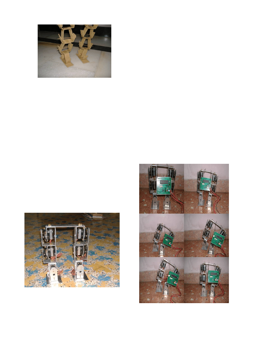
.
Figure 6 Proto type
D.
Specification and Fabrication of the model
Degrees of Freedom - 3D.O.F/Leg so total of 6D.O.F
(Hip, Knee and Ankle)
Dimensions:
Height – 230mm, Width – 200mm
Leg Length – 200mm
Foot pad: Length – 85mm, Width – 70mm
Connecting Link: Length – 165mm,
Width – 32 mm
Before Fabrication weight of the robot is roughly
estimated
Estimated Bracket weight: 50gms – 65gms
Servo motor: 55gms
Total estimated weight for a link
(Servomotor + Servomotor Bracket)
= 120gms
For 6 links (i.e. 2Legs): 720gms approx
Foot pad weight (2 legs):60gms.
Circuits & Batteries: 300 - 400gms approx
Total weight of the robot = 1.180Kg approx. The entire
robot structure has been fabricated from 1.5mm thickness
aluminium sheets. The fabricated model is shown in the figure
7. Actual Weight of the robot excluding batteries is 800grams
Figure 7 Fabricated model
III. W
ALKING
G
AIT
Stable walking Pattern can be obtained only if the Centre of
Mass and Centre of pressure are with in the supporting area
[3]. Generally walking cycle consists of two steps namely
Initialization and Walking
1) Initialization:
In the Initialization step the robot will be in
balanced condition and in this step the servomotors are made
to return to home position. This will certainly help the robot to
advance into the next step.
2) Walking:
Walking step is further classified into six phases.
Phase 1 – Double Support:
In this phase both the legs are in same line and the centre
of mass is maintained between the two legs.
Phase 2 – Single Support (Pre-Swing):
In this phase both the ankle joints are in actuated in roll
orientation which shifts the centre of mass towards
the
left leg and the right leg will be lifted up
from
the
ground.
Phase 3 – Single Support (Swing):
In this phase, the right leg is lifted further and made to
swing in the air. Hip and knee joints are actuated in
pitch orientation so that right leg is moved forward.
Phase 4 – Post Swing:
In this phase the lifted leg is placed down with the
actuation of ankle joints.
Phase 5 and 6 are the mirror image of Phase 2 and Phase 3.
After Phase 6, motion continues with a transition to Phase 1
and the walking continues.
Figure 8 Transition of phases
The Figure 8 shows the walking gaits transition from
double support to single support and then coming back to
double support (Phase 1- phase 4). It takes approximately 30
seconds to complete one walking cycle (all 6 phases). Bipedal
robot has a step length of approximately 10mm. The Robot
has the capability of carrying a dead weight of approximately
150gms.
IV.
C
ONTROLLING OF
B
IPEDAL
R
OBOT
Generally any robot has a combination of motors and
sensors, which are controlled by microcontrollers. There are
wide varieties of motors, sensors and microcontrollers
available. In this project low cost microcontroller and
actuators are used. There are Six D.O.F, each D.O.F has one
RC servomotor and it is controlled by 8051 architecture based
ATMEL 89C52 microcontroller.
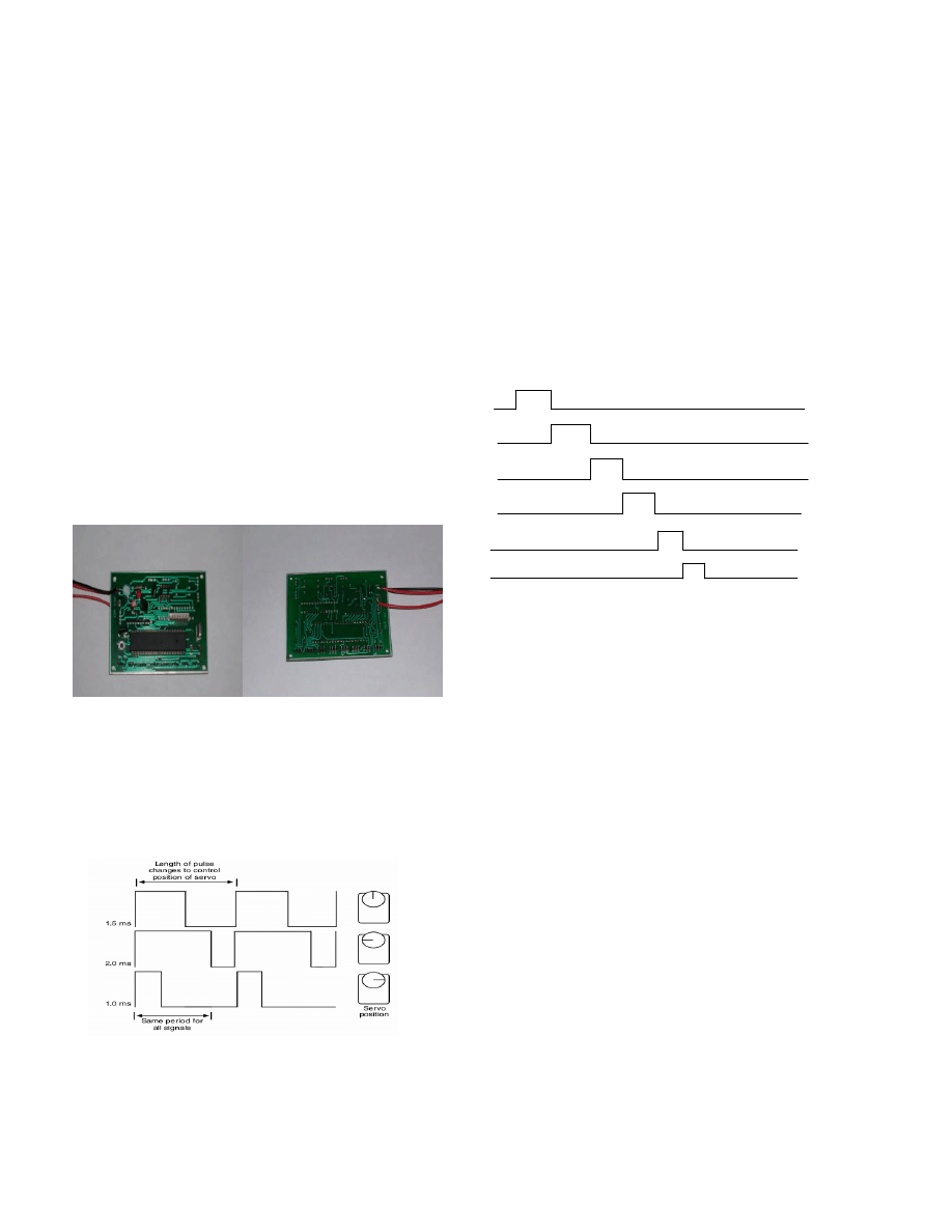
The robot controller board has been specifically designed
for this project and it measures 90X70mm. It is shown in the
figure 9. The controller board has the capability to control
upto eight actuators and it has a provision for providing
sensory inputs to the controller. The robot has the capability to
work in closed loop with the help of sensory inputs. The robot
is controlled and actuated using a pre-defined sequences and it
implements an open loop control and thus does not use
sensors.
Figure 9 Controller Board
RC Servomotor:
RC Servomotors are basically geared DC motors with
positional feedback control, which can accurately position the
shaft. The motor shaft of RC Servomotor is positioned by
Pulse Width Modulation (PWM). Generally Angles are coded
as pulse width, so based on the pulse width duration the motor
rotates.
The motor can rotate from 0˚ to 180˚ and it can be rotated
in a second. It is shown in the figure. In this project RC
Servomotor used has a torque of 14 kg-cm.
Algorithm:
All the Six motors are controlled and actuated
simultaneously while maintaining the previous positional
values. Initially, the first motor will be serviced with on-time
pulse period and during the off-time pulse period of the motor,
second motor will be serviced with on-time pulse period. This
type of actuation is continued till all the six motors are
serviced. Positional values loaded in the Look-up table and are
retrieved and pulses are sent to the motors accordingly. It is
shown in the figure below with various ON and OFF time
periods. No special algorithms are used for balancing the
bipedal robot. Currently, the walking gait was developed by
studying possible walking movements using the prototype and
by simulating various walking gaits using the ADAMS
software package. In the future we hope to add sensor-based
active balancing.
Motor 1
ON OFF
Motor 2
Motor 3
Motor 4
Motor 5
Motor 6
V. A
NALYSIS OF WALKING GAITS
Analysis of walking gaits can be carried out by finding the
Centre of Mass. Initially Centre of Mass is calculated from the
3D model by specifying the densities of the individual
components which are assembled in the robot. Initially
approximate density values are taken for calculating the centre
of mass. After fabricating the model individual joints masses
are taken and based on that centre of mass is calculated
manually to verify the location point. The values listed below
are calculated from 3D model using Pro-Engineer wild fire
Version2 software
.
Volume = 3.3326931e+05 mm
3
Surface area = 2.4295484e+05 mm
2
Average density =2.3501919e-06 Kg/ mm
3
Mass = 7.8324681e-01Kg
Center of gravity (Centre of Mass) with respect to
Assembly coordinate frame:
X = -1.1596342e+02 mm
Y = 7.0654738 mm
Z = -1.1453840e+02 mm
The movement of the centre of mass can be traced by plotting
the trajectory. Centre of Mass movements can be simulated
while walking and during different operations, which are
under study.

VI. W
ALKING
A
PPLICATIONS
Bipedal Robots are the fundamental block of any advanced
walking robots. By making the Bipedal robots fully
autonomous, it can be used in environment where human
cannot enter. Based on the analysis and study, the output of
this type of robots can be used for developing artificial limbs
for the physically challenged person.
VII. C
ONCLUSION
An extensive Literature Survey conducted for the project
gave profound insight on the requirements for building the
robot. Based on the Literature survey, the inputs for designing
the robot have been decided and Software model has been
created. After creating the software model it is fabricated and
tested.
VIII. F
UTURE
C
ONSIDERATIONS
The future advancement can be carried out in the project by
going for Embedded Processor that can process and transmit
the control signal faster to the actuators. Complex movements
can be achieved by increasing the Degrees of Freedom. Vision
system can help the robot to work autonomously. Remote
control through wireless mode can also be considered.
A
CKNOWLEDGMENT
Our Special thanks to Arun Joshua Cherian, Vannia raj
Muthandy, Prof. Jacky Baltes (University of Manitoba,
Canada) and Rodrigo da Silva Guerra (Osaka University,
Japan)
R
EFERENCES
[1] Andre Senior, and Sabri Tosunoglu, “Robust Bipedal
Walking: The Clyon Project,” The 18th Florida
Conference on Recent Advances in Robotics, FCRAR
2005, University of Florida, Gainesville, Florida, May 5-
6, 2005.
[2] Andre Senior and Sabri Tosunoglu – “Design of a Biped
Robot”, Florida Conference on Recent Advances in
Robotics, FCRAR, May25-26, 2006.
[3] John Anderson, Jacky Baltes, and Sara McGrath -
“Active balancing using gyroscopes for a small humanoid
robot”, a paper presented in Second International
Conference on Autonomous Robots and Agents (ICARA),
Massey University, December 2004. Pages: 470- 475.
[4] John Anderson, Jacky Baltes, and Sara McGrath –
“Active balancing in a small humanoid robot”. In
Proceedings of the 2004 FIRA Robot World Congress,
Busan, Korea, 2004.
[5] Jacky Baltes and Patrick Lam - “Design of walking gaits
for Tao-pie-pie, a small humanoid robot”, In Advanced
Robotics, 18(7):713-716, 2004.
[6] John Anderson, Jacky Baltes, and Sara McGrath (2003) –
“Stabilizing walking gaits using feedback from
gyroscopes”. In Proceedings of the Second
International Conference on Computational Intelligence,
Robotics, and Autonomous Systems 2003.
[7] Mehmet Ismet Can Dede, Salim Nasser, Shusheng Ye and
Sabri Tosunoglu - “Cerberus the Humanoid Robot: Part I
– Design”, The 18th Florida Conference on Recent
Advances in Robotics, FCRAR 2005, University of
Florida, Gainesville, Florida, May 5-6, 2005.
[8] Mehmet Ismet Can Dede, Salim Nasser, Shusheng Ye and
Sabri Tosunoglu - “Cerberus the Humanoid Robot: Part II
– Component Selection and Manufacturing”, The 18th
Florida Conference on Recent Advances in Robotics,
FCRAR 2005, University of Florida, Gainesville, Florida,
May 5-6, 2005.
[9] Mehmet Ismet Can Dede, Salim Nasser, Shusheng Ye and
Sabri Tosunoglu - “Cerberus the Humanoid Robot: Part
III – Software and Integration”, The 18th Florida
Conference on Recent Advances in Robotics, FCRAR
2005, University of Florida, Gainesville, Florida, May 5-
6, 2005.
[10] Ruixiang Zhang, Prahlad Vadakkepat and Chee-Meng
Chew – “Development and Walking control of Biped
Robot” http://mchlab.ee.nus.edu.sg/zhang/paper/jrnl.pdf
Document Outline
- I. INTRODUCTION
- II. Mechanical Design Of Bipedal robot
- III. Walking Gait
- IV. Controlling of Bipedal Robot
- V. Analysis of walking gaits
- VI. Walking Applications
- VII. Conclusion
- VIII. Future Considerations
Wyszukiwarka
Podobne podstrony:
więcej podobnych podstron