MASTER DRIVE UNIT
(KORDEL)
A1.00-1.50XL (A20-30XL) [C203]
PART NO. 1482613
630 SRM 795

SAFETY PRECAUTIONS
MAINTENANCE AND REPAIR
• When lifting parts or assemblies, make sure all slings, chains, or cables are correctly
fastened, and that the load being lifted is balanced. Make sure the crane, cables, and
chains have the capacity to support the weight of the load.
• Do not lift heavy parts by hand, use a lifting mechanism.
• Wear safety glasses.
• DISCONNECT THE BATTERY CONNECTOR before doing any maintenance or repair
on electric lift trucks.
• Disconnect the battery ground cable on internal combustion lift trucks.
• Always use correct blocks to prevent the unit from rolling or falling. See HOW TO PUT
THE LIFT TRUCK ON BLOCKS in the Operating Manual or the Periodic Mainte-
nance section.
• Keep the unit clean and the working area clean and orderly.
• Use the correct tools for the job.
• Keep the tools clean and in good condition.
• Always use HYSTER APPROVED parts when making repairs. Replacement parts
must meet or exceed the specifications of the original equipment manufacturer.
• Make sure all nuts, bolts, snap rings, and other fastening devices are removed before
using force to remove parts.
• Always fasten a DO NOT OPERATE tag to the controls of the unit when making repairs,
or if the unit needs repairs.
• Be sure to follow the WARNING and CAUTION notes in the instructions.
• Gasoline, Liquid Petroleum Gas (LPG), Compressed Natural Gas (CNG), and Diesel fuel
are flammable. Be sure to follow the necessary safety precautions when handling these
fuels and when working on these fuel systems.
• Batteries generate flammable gas when they are being charged. Keep fire and sparks
away from the area. Make sure the area is well ventilated.
NOTE:
The following symbols and words indicate safety information in this
manual:
WARNING
Indicates a condition that can cause immediate death or injury!
CAUTION
Indicates a condition that can cause property damage!

Master Drive Unit (Kordel)
Table of Contents
TABLE OF CONTENTS
General ...............................................................................................................................................................
Description .........................................................................................................................................................
Upper Section.................................................................................................................................................
Lower Section.................................................................................................................................................
Drive Unit Repair ..............................................................................................................................................
Remove ...........................................................................................................................................................
Disassemble ...................................................................................................................................................
Assemble ........................................................................................................................................................
General.......................................................................................................................................................
Assemble Component Subassemblies ......................................................................................................
Assemble Components Into Lower Section ..............................................................................................
Assemble Upper and Lower Sections .......................................................................................................
Install .............................................................................................................................................................
Check and Change Transmission Oil................................................................................................................
Tooth Contact Pattern Adjustment ...................................................................................................................
Troubleshooting..................................................................................................................................................
This section is for the following models:
A1.00-1.50XL (A20-30XL) [C203]
©2002 HYSTER COMPANY
i

"THE
QUALITY
KEEPERS"
HYSTER
APPROVED
PARTS
630 SRM 795
Description
General
This section covers the description of the KORDEL
master drive unit. It also covers removal, disassem-
bly, assembly, and installation procedures. The trac-
tion motor and steering repair procedures are in sep-
arate service manuals. This service manual focuses
on the main parts of the MDU, which are the upper
and lower sections, pinion (motor) and large (helical)
gear set, the pinion and spiral bevel gear set, roller
bearings, and the axle and wheel.
NOTE:
Some A1.00-1.50XL (A20-30XL) units come
equipped with an MDU manufactured by ZF
GOTHA. The service manuals listed below pro-
vide information on how to repair the ZF MDU along
with the traction motor and steering system.
• Master Drive Unit (ZF) 630 SRM 794
• DC Motor Maintenance 620 SRM 294
• Steering System 1600 SRM 796
The two types of MDUs used in the manufacturing
of this lift truck do have some minor mechanical dif-
ferences, but are similar in form, fit, and function.
However, when repairing or replacing parts on the
MDU, do not use parts from one model of MDU on
the other MDU.
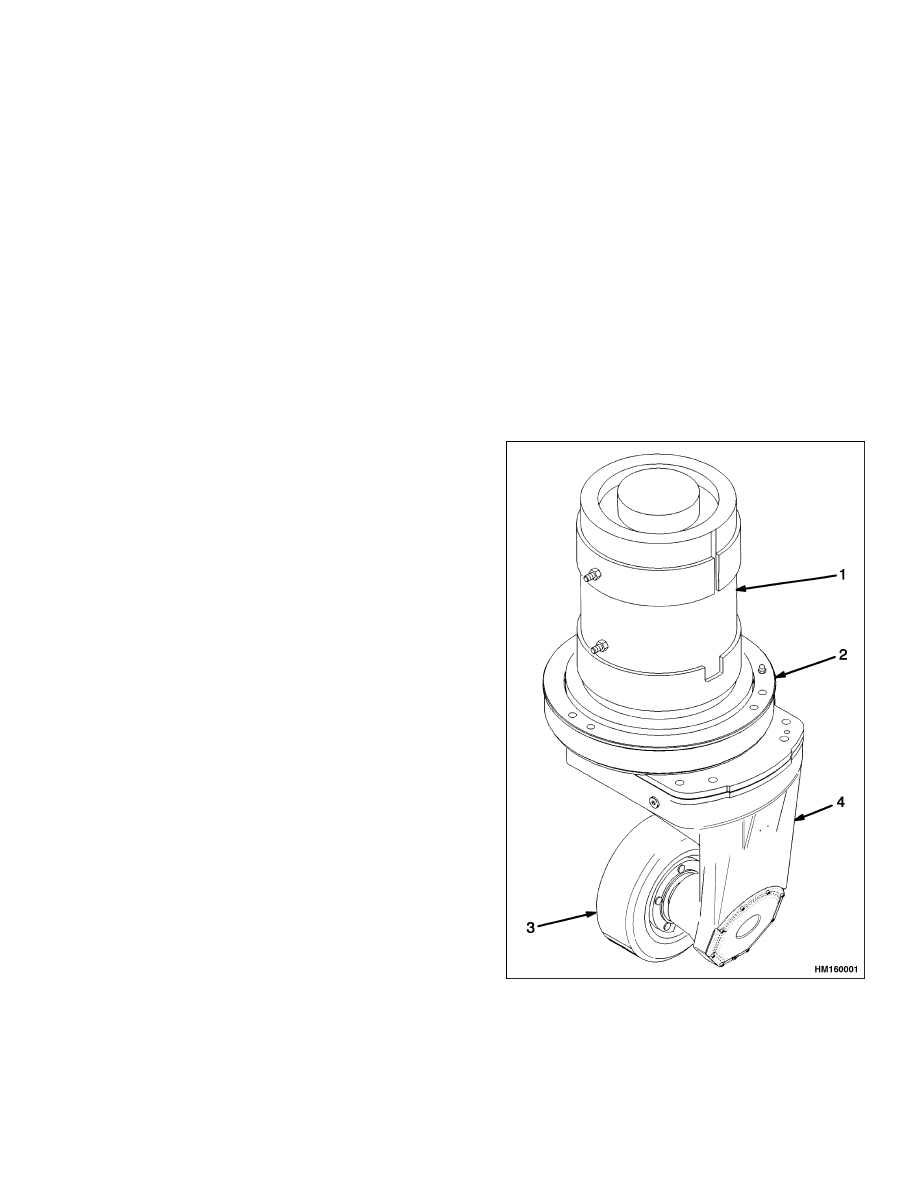
Description
The transmission (MDU) is a steered drive that uti-
lizes bevel and helical gears in order to propel the lift
truck. See Figure 1 and Figure 2. The MDU has a to-
tal gear ratio of 20:37.
The general operating procedure of the MDU consists
of a ground bevel gear set forming the crown wheel
and pinion which drives the wheel shaft. A further
reduction occurs between the motor pinion gear and
the first helical gear, which in turn drive the crown
wheel and pinion.
The MDU is composed of two main components: the
upper section and the lower section. See Figure 1.
UPPER SECTION
The upper section is made up of two parts. The first
part is the centering (or mounting) ring. This ring
fits on the cover plate (the second part of the upper
section) and is the mounting platform for the traction
motor. The cover plate is also in the form of a ring,
but with a rectangular-shaped bottom. This bottom
is in the same shape and size as the top portion of
the lower section because it covers the gears that are
housed in this part of the lower section.
The upper section performs three functions within
the MDU. The first function is to hold the traction
motor in place. The second function is to bring to-
gether the lower section and traction motor as one
unit, allowing this unit to be attached to the lift truck
frame. The third function performed by the upper
section is to cover and protect the roller bearings and
gears that allow the MDU to turn with the lift truck.
1.
TRACTION MOTOR
2.
UPPER SECTION
3.
WHEEL AND TIRE
4.
LOWER SECTION
Figure 1. Master Drive Unit
1
Description
630 SRM 795
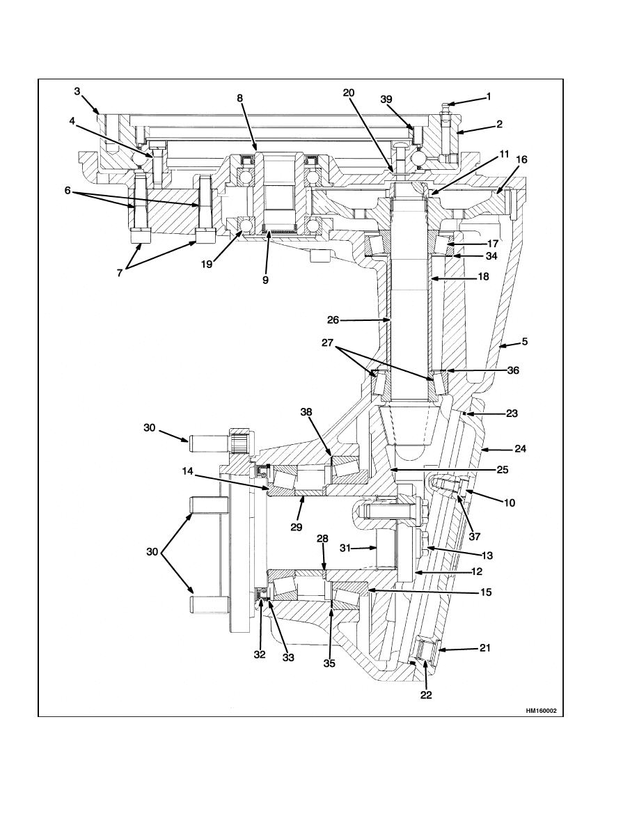
Figure 2. Master Drive Unit Cross-Section
2

630 SRM 795
Drive Unit Repair
Legend for Figure 2
1.
SOCKET SCREW
2.
STEERING BEARING
3.
UPPER SECTION
4.
SCREW
5.
LOWER SECTION
6.
SCREWS
7.
SPRING WASHERS
8.
PINION
9.
LOCKING CAP
10. SCREWS
11. NUT
12. DISC
13. SCREWS
14. BEARING
15. TAPER ROLLER BEARING
16. HELICAL GEAR
17. TAPER ROLLER BEARING
18. DISTANCE BUSH
19. TAPER BALL BEARING
20. O-RING
21. OIL PLUG
22. COPPER RING
23. O-RING
24. LOWER COVER
25. BEVEL GEAR
26. SPIRAL BEVEL PINION
27. TAPER ROLLER BEARING
28. SPACER
29. DISTANCE RING
30. WHEEL STUDS
31. FLANGE SHAFT
32. SEAL
33. SNAP RING
34. SHIM
35. SHIM
36. SHIM
37. SPRING WASHERS
38. SHIM
39. DOWEL PIN
Steering is performed by the steering control unit.
See service manual Steering Control Unit 1600
SRM 797 for more information about this function.
The steering control unit uses a combination of a hy-
draulic motor, chain, and gear set to turn the lift
truck in all directions.
LOWER SECTION
The lower section houses several roller bearings,
gears, and a gear shaft. The spline on the end of the
motor armature turns the pinion gear mounted in
the upper section of the MDU.
Drive Unit Repair
REMOVE
1.
Move the steering wheel so that the drive wheel
is in a position for straight travel. See Figure 1
and Figure 5.
2.
Open the front hood panel and fasten the panel
in place.
3.
Remove the rear hood panel and place off to the
side.
4.
Disconnect and remove the battery. Use the bat-
tery removal procedure described in Periodic
Maintenance 8000 SRM 798.
5.
Remove the overhead guard. See Frame 100
SRM 793 for more information on how to remove
this piece of equipment.
6.
Put a pan under the MDU drain plug and remove
the drain plug. After oil has completely drained,
install the drain plug. Tighten plug to 22 N•m
(16 lbf ft). Refer to Check and Change Transmis-
sion Oil for information on how to drain and fill
transmission oil.
WARNING
The counterweight is very heavy. Make sure
the sling, chain, eyebolts, and crane or lifting
device have the capacity to lift the counter-
weight.
7.
Remove the counterweight. Refer to Frame 100
SRM 793 for instructions on how to remove the
counterweight.
8.
Put blocks under the lift truck frame to remove
the MDU from the truck. See HOW TO PUT
THE LIFT TRUCK ON BLOCKS in the Oper-
ating Manual or Periodic Maintenance 8000
SRM 798.
3
Drive Unit Repair
630 SRM 795
CAUTION
The traction motor is heavy. Secure it with a
lifting device when removing it from the lift
truck.
9.
Remove the six socket-head capscrews that fas-
ten the traction motor to the upper section of the
MDU. Lift the motor and set it out of the way. Do
not damage the spline on the end of the motor ar-
mature. Use rope to fasten the motor to prevent
it from falling.
10. Loosen the six hex head bolts and nuts that hold
the MDU in place to the frame.
11. Remove the steering chain and chain tensioner.
12. Put a sling under the lift truck frame on the side
of the MDU that faces toward the front of the
truck. Make sure the lifting device and sling are
rated to lift approximately 450 kg (1000 lb).
WARNING
There are close clearances underneath the
lift truck when removing the MDU. Never put
hands, arms, head, or legs between parts in
this area.
WARNING
If the MDU falls, it can cause a serious injury.
Secure the MDU with a lifting device to hold it
in a vertical position.
13. Hold the MDU and raise the lift truck frame so
that the MDU is free. Lower the MDU to the floor
and remove it from under the lift truck. Lower
the lift truck frame back onto the blocks.
DISASSEMBLE
1.
Remove the five wheel nuts and the wheel. See
Figure 2, Figure 3, Figure 4, and Figure 5.
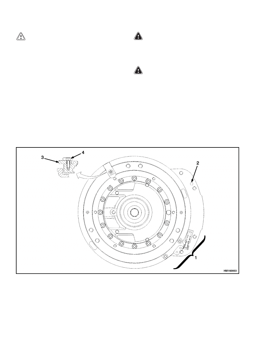
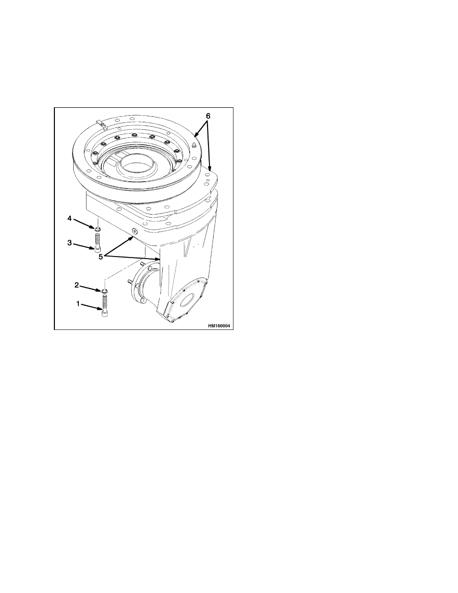
1.
STEERING LOCKS AND CHAIN TENSIONER
2.
SOCKET SCREW AND SPRING WASHER
3.
STOP (2)
4.
SCREW AND WASHER
Figure 3. Upper Section of MDU
4
630 SRM 795
Drive Unit Repair
2.
Separate the upper section from the lower section
by removing the 14 hex head bolts and washers.
The bolts and washers are underneath the long,
rectangular-shaped portion of the lower section.
See Figure 4.
1.
HEX HEAD
BOLT (4)
2.
WASHER (4)
3.
HEX HEAD
BOLT(10)
4.
WASHER (10)
5.
LOWER SECTION
6.
UPPER SECTION
Figure 4. Separating Sections
3.
The upper section can be disassembled into two
sections.
Remove the centering ring from the
cover ring by unfastening the 16 screws that hold
the two sections together.
4.
Remove the dowel pin, socket screws, and spring
washers from the top part of the lower section.
5.
Unfasten the two stops along with the screws and
washers that hold them in place. See Figure 3.
6.
Remove the steering bearing from the cover by
removing the screws that hold the steering bear-
ing to it.
7.
Unfasten the housing and cover.
8.
Remove the locking cap from the pinion and re-
move the pinion from the housing.
9.
Remove the lower gearbox cover from the gear-
box housing by removing the screws and spring
washers that hold it in place.
10. Remove the disc and screws from the flange
shaft.
11. Remove the bevel gear through the lower cover
aperture. Remove the bevel gear’s bearing cone
and cup.
12. Remove the helical gear.
13. Inspect the bearing cup and remove if damaged.
14. Remove the distance bush from the pinion.
NOTE:
The remaining steps provide instructions on
how to further disassemble the components removed
in Step 1 through Step 14.
15. The flange shaft subassembly is pressed fitted.
Use an extraction tool to extract the wheel studs,
bearings, distance rings, and spacers from the
wheel shaft.
16. Inspect the bearing cup and remove if damaged.
17. Remove the copper ring, oil plug, and O-ring from
the lower cover subassembly.
18. Remove the ball bearings and O-rings from the
grease channels of the steering bearing and up-
per cover.
5
Drive Unit Repair
630 SRM 795
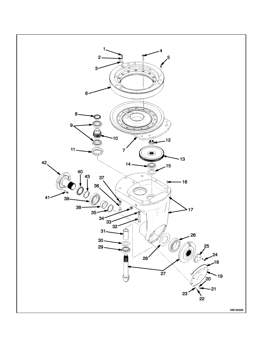
Figure 5. Master Drive Unit Parts
6

630 SRM 795
Drive Unit Repair
Legend for Figure 5
1.
SCREW (1)
2.
WASHER (24)
3.
BUFFER (1)
4.
SCREW (16)
5.
LUBE FITTING (2)
6.
CENTERING RING (PART OF UPPER SECTION)
7.
COVER PLATE (PART OF UPPER SECTION)
8.
OIL SEAL
9.
LARGE ROLLER BEARING (2)
10. MOTOR PINION GEAR
11. COVER
12. NUT
13. LARGE (HELICAL) GEAR
14. ROLLER BEARING
15. SHIM
16. DOWEL PIN
17. LOWER SECTION
18. O-RING
19. COVER
20. SEAL (2)
21. PLUG
22. SCREW (8)
23. WASHER
24. SCREW (3)
25. DISC
26. ROLLER BEARING
27. SPIRAL BEVEL (STEERING) PINION AND GEAR
SET
28. SHIM
29. BEARING SET
30. SHIM
31. SPACER
32. HEX HEAD BOLT (4)
33. WASHER (14)
34. SCREW
35. SPACER
36. HEX HEAD BOLT (10)
37. WASHER
38. DISC
39. ROLLER BEARING
40. OIL SEAL
41. WHEEL BOLTS (5)
42. WHEEL SHAFT
43. CIRCLIP
ASSEMBLE
General
NOTE: The pinion gear and the large gear must be
replaced as a set. The spiral bevel pinion and gear
set must also be replaced as a set.
NOTE: Where screw tightening torques are unspec-
ified in the text, torque as follows:
M8 = 23 N•m (17 lbf ft)
M10 = 46 N•m (34 lbf ft)
Assemble Component Subassemblies
1.
Prepare the lower section housing for assembly
by ensuring it is clean and free of any excess
grease and dirt. Locate the shims into their re-
spective bearing bores in the housing. See Fig-
ure 2, Figure 3, Figure 4, and Figure 5.
2.
Place the outer shells of the taper roller bearings
into the housing.
3.
Press one ball bearing into the housing.
4.
Apply Loctite
®
574 to the cover location for the
seal and fit the seal.
5.
Press the wheel studs into the wheel shaft sub-
assembly.
6.
Press the bearing cup onto the shaft and fit the
distance ring and spacer.
7.
Apply Loctite
®
620 to the bearing diameter of the
spiral bevel pinion and press fit the bearing cup
into position.
8.
Press the bearing cup onto the bevel gear.
9.
Insert the O-ring into its groove in the lower
cover housing. Install the oil plug over the cop-
per ring into the cover.
10. Insert one O-ring into the upper cover in line with
the breather and two O-rings in line with the
grease channels in the steering bearing.
Assemble Components Into Lower Section
NOTE:
Where screw tightening torques are unspeci-
fied in the text, torque as follows:
M8 = 23 N•m (17 lbf ft)
M10 = 46 N•m (34 lbf ft)
1.
Feed the assembled spiral pinion through the
lower cover aperture and place it into position.
2.
Place the distance bush onto the pinion.
3.
Install the bearing cup.
4.
Install the helical gear and the nut. To achieve
the correct bearing preload, the breakaway
torque at the nut must be 0.5 to 0.8 N•m (4.4 to
7.1 lbf in).
7

Drive Unit Repair
630 SRM 795
5.
Tighten the nut to 280 N•m (206 lbf ft). Secure
the nut by peening after the bearing preloads and
after the bevel gear tooth contact pattern has
been correctly set. Do not apply radial force to
the pinion when peening the nut.
6.
Pass the bevel gear through the lower cover aper-
ture and locate its bearing cone into the cup,
which was previously installed in the housing.
7.
Place the assembled flange shaft into position
through the bearing.
8.
Apply Loctite
®
566 to the screw threads which
are used to hold the disc in place. Tighten to
130 N•m (96 lbf ft).
9.
Recheck the breakaway torque at the nut.
It
must now be 1.0 to 1.5 N•m (8.9 to 13.3 lbf in).
Also, check and adjust, if necessary, the tooth
contact pattern of the bevel gear set.
10. Mount the lower gear box cover onto the gear-
box housing so that the oil hole is at the lowest
point when the gearbox is mounted in the truck.
Fix the cover in position with screws and spring
washers.
11. Push the locking cap into the pinion and assem-
ble it into the housing. Close the housing with
the cover with screws and spring washers. As-
semble the steering bearing to the cover with
screws. Place the two stops into their positions
and secure with screws and washers.
12. Clean and remove any oil from the mounting
faces of the upper gearbox cover and the gear
housing.
Apply Loctite
®
574 to the mounting
faces and fit the upper cover to the housing.
Secure with dowel pin, socket screws, and spring
washers.
Assemble Upper and Lower Sections
NOTE:
The large ball bearing is part of the upper
section. The upper section and the ball bearing are
replaced as a unit. See Figure 4 and Figure 5.
NOTE:
Where screw tightening torques are unspeci-
fied in the text, torque as follows:
M8 = 23 N•m (17 lbf ft)
M10 = 46 N•m (34 lbf ft)
1.
Attach the centering ring to the cover plate ring
by inserting and tightening the 16 screws.
2.
Align the upper section on top of the lower sec-
tion, taking care to make sure the holes in both
sections line up.
3.
Attach the two sections together by inserting and
tightening the 14 hex head bolts, which are lo-
cated underneath the top part of the lower sec-
tion. See Figure 4.
INSTALL
1.
Use a crane and chain or sling with a capacity
rating of 450 kg (1000 lb) to lift the frame. Lift
the frame for clearance to slide the MDU under
the frame. Lay the MDU on the floor and slide it
under the drive chassis.
WARNING
If the MDU falls, it can cause a serious injury.
Secure the MDU with a lifting device to hold it
in a vertical position.
2.
Move the MDU into approximate alignment un-
der the frame and with the holes on the frame.
3.
Hold the MDU in the vertical position through
the hole in the plate on the truck frame. Raise
the frame and remove the blocks.
Lower the
frame and align the six bolt holes on the upper
section (centering ring) and the frame.
4.
Once both sets of holes are aligned, join the two
together by inserting and tightening the six hex
head bolts. Tighten to 25 N•m (18 lbf ft).
5.
Place the traction motor on the MDU so that the
holes on the motor flange line up with the holes
on the inside of the cover ring.
6.
Install the steering chain and chain tensioner.
See service manual Steering System 1600 SRM
796 for more information on steering system re-
pair, installation, and adjustments.
8
630 SRM 795
Check and Change Transmission Oil
Check and Change Transmission Oil
WARNING
After a long period of operation, transmission
oil becomes very hot. Use heat-resistant gloves
to protect against serious burns and other in-
juries.
The MDU assembly has one oil compartment. See
Figure 6. It is recommended that after 500 hours of
initial operation, the oil be changed. After the ini-
tial service, the oil needs to checked and changed af-
ter every 2000 hours of operation. The amount of
oil used is 4.2 liter (4.4 qt). Access to the filler in-
let screw is gained by removing the tow pin from its
slot on the counterweight. Turn the MDU counter-
clockwise until the inlet screw and hole become visi-
ble through the tow pin slot. To drain and change the
gear oil, do the following.
1.
Remove the inlet screw.
2.
Position a suitable oil catch container under-
neath the oil outlet screw. The container must
have a capacity of at least 5 liter (5.3 qt).
3.
Remove the oil outlet screw and seal ring.
4.
Allow the gear oil to fully drain into an appropri-
ate container for at least 5 minutes.
5.
Clean magnet on the oil outlet screw and reinsert
the screw with a new seal ring. Tighten the screw
to 22 N•m (16.23 lbf ft).
6.
Fill the MDU with new gear oil. A small hand
pump may be needed to feed the oil in under pres-
sure due to the viscosity of the oil. The correct oil
level is achieved when it is level with the lip of
the oil inlet hole. During filling, make sure that
air does not become trapped within the transmis-
sion. Trapped air can be removed by turning the
wheel shaft.
7.
Insert the oil inlet screw together with a new seal
ring into the oil inlet hole and tighten to 22 N•m
(16.23 lbf ft).
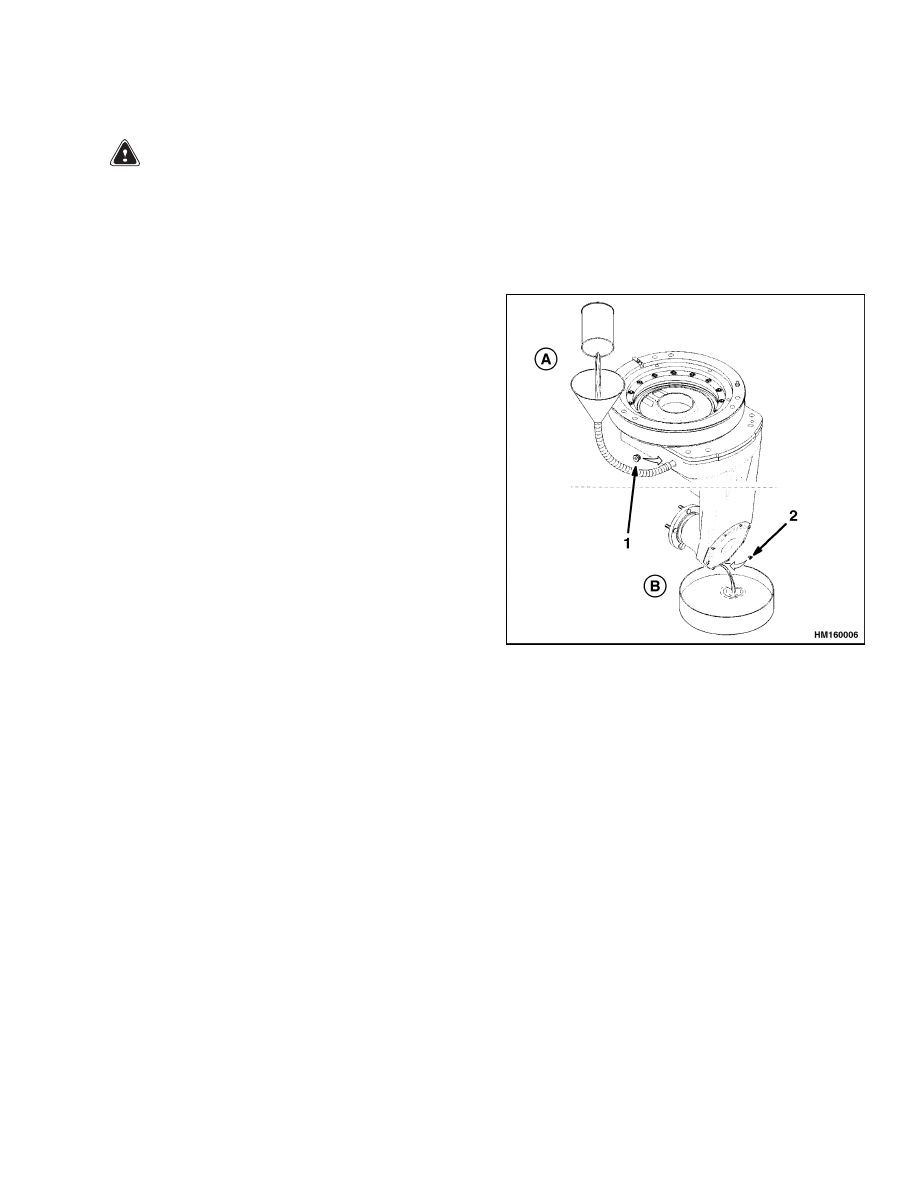
A. STEP 2 - FILL OIL
B. STEP 1 - DRAIN OIL
1.
INLET SEAL RING AND SCREW
2.
OUTLET SEAL RING AND SCREW
Figure 6. MDU Lubrication
9
Tooth Contact Pattern Adjustment
630 SRM 795
Tooth Contact Pattern Adjustment
See Table 1 on for information on how to adjust and
correct the tooth contact pattern of the bevel gear set.
Also, Figure 2 and Figure 5 can be referenced for the
locations of the shims and bevel gear set.
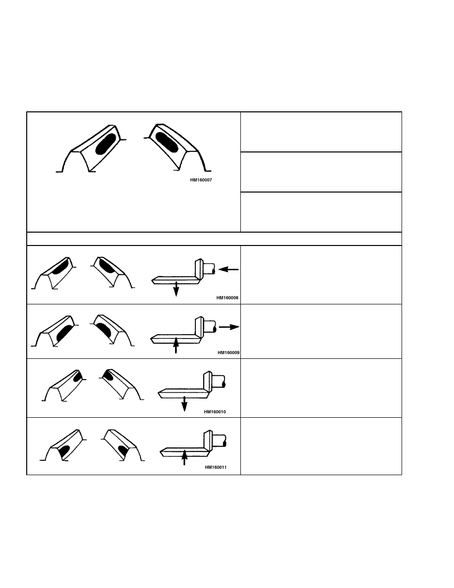
Table 1. Tooth Contact Pattern
Step 1. The correct preloading of the taper
roller bearings is established by changing
the thickness of the shim and spacer (38 and
28 in Figure 2).
Step 2. To set the correct tooth contact
pattern at the bevel gear set, first apply
marking ink to the gears and rotate them
until the pattern is visible.
Correct Contact Pattern
Step 3. Compare the contact pattern
with the information below. To correct the
pattern, change the thickness of the shims
(35 and 36 in Figure 2).
Wrong Tooth Contact Pattern
Tip Contact
The spiral bevel pinion is too far from the
center of the spiral bevel gear.
Base Contact
The spiral bevel pinion is too close to the
center of the spiral bevel gear.
Inner Contact
The spiral bevel pinion is too far from the
center of the spiral bevel pinion.
Outer Contact
The spiral bevel pinion is too far from the
center of the spiral bevel pinion.
10

630 SRM 795
Troubleshooting
Troubleshooting
PROBLEM
POSSIBLE CAUSE
PROCEDURE OR ACTION
Lift truck will not move.
Motor not operating.
Check key switch. Check motor and
battery connection.
Damaged gears or bearings.
Replace gears or bearings.
Master drive unit makes
noise.
There is not enough lubricant or
the wrong kind of lubricant is being
used.
Add lubricant or drain and fill with
correct lubricant.
Dry or damaged bearings.
Lubricate bearings or replace with
new bearings.
Wrong bearing or gear adjustment.
Replace with correct bearing or ad-
just gears to correct alignment.
Worn or damaged gears.
Replace gears.
Oil leaks.
Loose case cover.
Tighten case cover.
Loose drain or fill plugs.
Tighten drain or fill plug.
Damaged plug seals.
Replace plug seals.
Worn or damaged axle oil seal.
Replace axle oil seal and check oil
level. Fill if necessary.
11

NOTES
____________________________________________________________
____________________________________________________________
____________________________________________________________
____________________________________________________________
____________________________________________________________
____________________________________________________________
____________________________________________________________
____________________________________________________________
____________________________________________________________
____________________________________________________________
____________________________________________________________
____________________________________________________________
____________________________________________________________
____________________________________________________________
____________________________________________________________
____________________________________________________________
____________________________________________________________
____________________________________________________________
____________________________________________________________
____________________________________________________________
12

TECHNICAL PUBLICATIONS
630 SRM 795
4/00 Printed in United Kingdom
Document Outline
- toc
- tables
Wyszukiwarka
Podobne podstrony:
więcej podobnych podstron