
OPERATION MANUAL
OM Series
Quarter-Turn Electrical Actuator
SEPTEMBER, 2013 2nd

Quarter Turn Actuator 【OM series】
Sun Yeh Ele. Ind. Co., Ltd. | 2013.09
i
INDEX
OM-1 , OM-A , OM-A-M 12V , 24V DC On-Off Controller
.........................................................9
OM-1 , OM-A , OM-A-M 12V , 24V AC On-Off Controller
........................................................ 10
OM-1 , OM-A , OM-A-M 110V , 220V AC 1-Phase On-Off Controller
......................................... 11
OM-1 , OM-A , OM-A-M 110V , 220V AC 1-Phase On-Off Controller , 75% duty cycle
OM-1 , OM-A , OM-A-M 110V , 220V AC 1-Phase On-Off Controller , Coupling Board
OM-1 , OM-A , OM-A-M 110V , 220V AC 1-Phase
On-Off Controller , Analog Signal Output
OM-1 , OM-A , OM-A-M 24V AC/DC On-Off Controller , Analog Signal Output
............................ 15
OM-1 , OM-A , OM-A-M 24V DC Modulating Controller
......................................................... 16
OM-1 , OM-A , OM-A-M 24V AC Modulating Controller
.......................................................... 17
OM-1 , OM-A , OM-A-M 110V , 220V AC 1-Phase Modulating Controller
................................... 18
OM-1 , OM-A , OM-A-M 24V AC Modulating Controller , MODBUS
.......................................... 19
OM-1 , OM-A , OM-A-M 24V DC Modulating Controller , MODBUS
.......................................... 20
OM-1 , OM-A , OM-A-M 110V , 220V AC 1-Phase
Modulating Controller , MODBUS
OM-2 ~ OM-6 12V DC On-Off Controller
............................................................................ 22
OM-2 ~ OM-12 , OM-F , OM-G 24V DC On-Off Controller
...................................................... 22
OM-2 ~ OM-6 12V AC On-Off Controller
............................................................................ 23
OM-2 ~ OM-12 , OM-F , OM-G 24V AC On-Off Controller
...................................................... 23
OM-7 ~ OM-10 12V DC On-Off Controller
.......................................................................... 24
BM-2 , OM-2 ~ OM-13 , OM-F , OM-G 110V , 220V AC 1-Phase On-Off Controller
OM-2 ~ OM-13 , OM-F , OM-G 110V , 220V AC 1-Phase On-Off Controller , Coupling Board
BM-2 , OM-2 ~ OM-13 220V , 380V , 440V AC 3-Phase On-Off Controller
................................. 27
OM-2 ~ OM-8 110V , 220V AC 1-Phase On-Off Controller , 75% duty cycle
............................... 28
OM-9 ~ OM-13 110V AC 1-Phase On-Off Controller , 50% duty cycle
....................................... 29
OM-9 ~ OM-13 220V AC 1-Phase On-Off Controller , 50% duty cycle
....................................... 30
OM-2 ~ OM-13 110V , 220V AC 1-Phase On-Off Controller , Analog Signal Output
OM-2 ~ OM-13 220V , 380V , 440V AC 3-Phase On-Off Controller , Analog Signal Output
OM-2 ~ OM-6 12V DC Modulating Controller
...................................................................... 33

Quarter Turn Actuator 【OM series】
Sun Yeh Ele. Ind. Co., Ltd. | 2013.09
ii
OM-2 ~ OM-12 , OM-F , OM-G 24V AC Modulating Controller
................................................ 34
OM-2 ~ OM-8 , OM-F , OM-G 110V , 220V AC 1-Phase Modulating Controller
........................... 35
OM-2 ~ OM-13 220V , 380V , 440V AC 3-Phase Modulating Controller
..................................... 36
OM-2 ~ OM-8 110V , 220V AC 1-Phase Modulating Controller , 75% duty cycle
OM-9 ~ OM-13 110V AC 1-Phase Modulating Controller , 50% duty cycle
................................. 38
OM-9 ~ OM-13 220V AC 1-Phase Modulating Controller , 50% duty cycle
................................. 39
OM-2 ~ OM-13 110V , 220V AC 1-Phase On-Off Controller , Local Control Unit
OM-2 ~ OM-13 220V , 380V , 440V AC 3-Phase On-off Controller , Local Control Unit
OM-2 ~ OM-8 110V , 220V AC 1-Phase Modulating Controller , Local Control Unit
OM-2 ~ OM-8 110V , 220V AC 1-Phase
Modulating Controller , Local Control Unit , 75% duty cycle
OM-9 ~ OM-13 110V AC 1-Phase Modulating Controller , Local Control Unit , 50% duty cycle
OM-9 ~ OM-13 220V AC 1-Phase Modulating Controller , Local Control Unit , 50% duty cycle
OM-2 ~ OM-13 110V , 220V AC 1-Phase
On-off Controller , Local Control Unit , Analog Signal Output
OM-2 ~ OM-13 220V , 380V , 440V AC 3-Phase
On-off Controller , Local Control Unit , Analog Signal
BM-2, OM-A, OM-A-M, OM-1~OM-13, OM-F,OM-G 110V,220V AC 1-Phase
– Travel Cam & Limit Switches ................................................................... 49
Part A: Suitable for OM-1~OM-13、OM-A、OM-A-M、OM-F、OM-G
.................................. 53
Part B: Suitable for OM-1、OM-A、OM-A-M (MODBUS optional)
Quarter Turn Actuator 【OM series】
Sun Yeh Ele. Ind. Co., Ltd. | 2013.09
1
OVERVIEW
Sun Yeh electric quarter-turn actuators offer a range of 35Nm to 4500Nm torque.
Product design is based on a self-locking worm drive principal, which provides for a smooth
running, dependable, robust drive system. All models are ISO 5211 compliant, have a visual
position indicator on top of actuator cover and manual override except BM-2 and OMA. The
manual operation is non-clutch design that can be operated without any lever, clutch or
brake upon power outage. This design has already won the new Patent in Taiwan, U.S.A.
and China.
Features
30% duty cycle at rated torque.
Self-locking function.
Built-in thermal protection prevents motor burning out. AC motor is 125°C (257°F) and
90°C (194°F) for DC motor. (The 75% duty cycle actuator uses DC motor.)
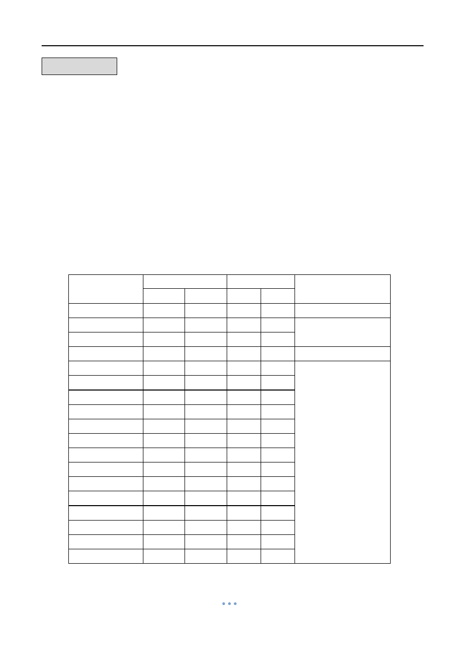
Model
Max. Torque
Weight
Manual Override
Nm
lbin
Kg
lb
OM-A
50
443
3
6.61
N/A
OM-A-M
50
443
3
6.61
Lever
OM-1
35
310
2
4.41
BM-2
120
1063
5.5
12.13
N/A
OM-F
65
576
11
24.25
Hand-wheel
OM-2
90
797
11
24.25
OM-G
90
797
11
24.25
OM-3
150
1328
11
24.25
OM-4
400
3542
20
44.09
OM-5
500
4427
20
44.09
OM-6
650
5756
20
44.09
OM-7
1000
8855
32
70.55
OM-8
1500
13282
32
70.55
OM-9
2000
17709
71
156.53
OM-10
2500
22137
71
156.53
OM-11
3000
26564
72
158.73
OM-12
3500
30991
72
158.73
OM-13
4500
39846
106
233.69

Quarter Turn Actuator 【OM series】
Sun Yeh Ele. Ind. Co., Ltd. | 2013.09
2
IMPORTANT NOTICES
1. Check for correct voltage prior to wiring.
2. Turn power off before servicing or for maintenance purpose.
3. Use sealant to seal conduit connections after wiring to prevent dusting or water
contamination.
4. The angle of electric actuator installation must be between 0~180 degree. Do not install
upside down or below the horizontal.
5. When more than one electric actuator needed to operate simultaneously, please connect
with the individual cables or install the coupling board.
6. Not intended for vacuum spaces and avoid installing near explosive atmospheres.
7. Actuators should be placed at clean and dry place for storage, and protected with outer
carton from being affected by great temperature difference or serious vibration.
8. To avoid functional failure caused by statics, do not touch any components on the PCB
with metal tools or bare hands.
9. Please connect the ground wire to PE inside the electric actuator.
10. The warranty period of our products is one year.
Duty Cycle
– compliance to IEC standard
"Duty cycle" means the starting frequency.
The formula: Running Time ÷ (Running time + Rest Time) × 100% = duty cycle
Rest Time = Running Time × (1- duty cycle) ÷ duty cycle
For example: The running time for OM-2 is 15 sec.
30% duty cycle 15 × [ ( 1
– 30%) / 30% ] = 35 The rest time will be 35 sec.
75% duty cycle 15 × [ ( 1
– 75%) / 75% ] = 5 The rest time will be 5 sec.
If the duty cycle is higher, the rest time will be shortened. It means the starting frequency
will be higher.
CAUTION !
For the 3-Phase on-off controller actuator, please use the
hand-wheel to turn the actuator to 45 degree before test.
** If the direction is opposite after supplying power, please change
any two of the U, V, W.
!
Quarter Turn Actuator 【OM series】
Sun Yeh Ele. Ind. Co., Ltd. | 2013.09
3
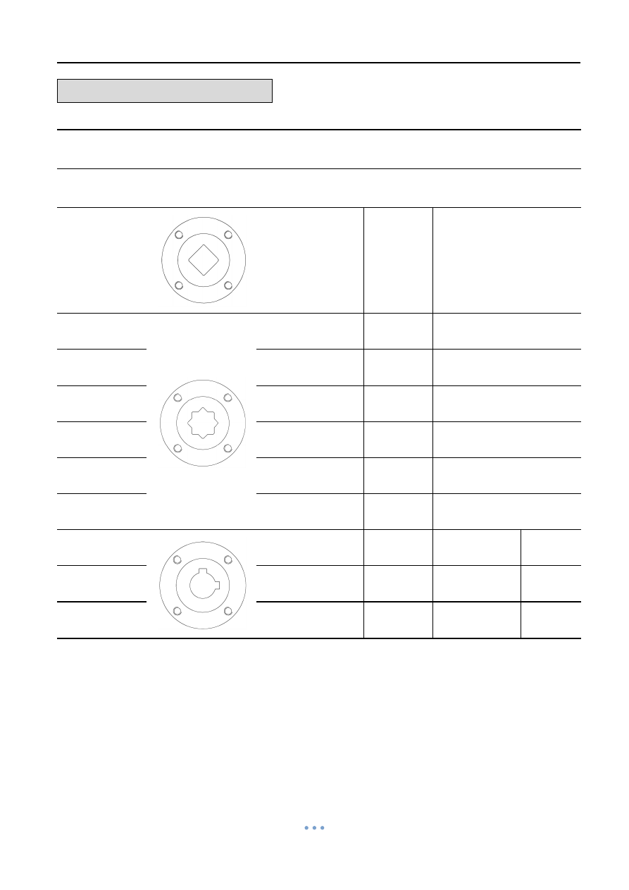
STANDARD MOUNTING
Model
Mounting
Flange
Shaft
Depth of
shaft
Key
(ISO 5211)
mm
inch
mm
inch
mm
inch
BM-2
F07
22
0.87
30
1.18
N/A
OM-A
F05 / F07
17
0.67
20
0.78
N/A
OM-A-M
F05 / F07
17
0.67
20
0.78
N/A
OM-1
F03 / F05
14
0.55
17
0.67
N/A
OM-F, OM-G
F07
22
0.87
30
1.18
N/A
OM-2~OM-3
F07
22
0.87
30
1.18
N/A
OM-4~OM-6
F10
36
1.38
40
1.57
N/A
OM-7~OM-8
F12 or F14
35
1.38
60
2.36
10 ×10
0.39×0.39
OM-9~OM-12
F14 or F16
75
2.95
100
3.94
12 ×10
0.47×0.39
OM-13
F16 / F25
72
2.83
110
4.33
20 ×12
0.79×0.47
Quarter Turn Actuator 【OM series】
Sun Yeh Ele. Ind. Co., Ltd. | 2013.09
4
SPECIFICATION
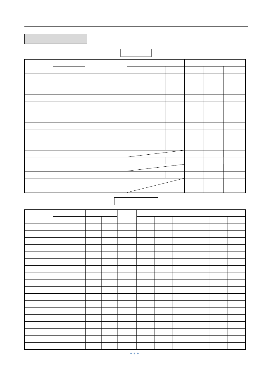
12V/24V
Model No.
Max Torque Speed
(90°)
Motor
Power
12V DC/AC
24V DC/AC
Nm
lb-in
Run
Start
Lock
Run
Start
Lock
BM-2
-
-
-
-
-
-
-
-
-
-
OM-A
50
443
20s
10W
1.3A
1.5A
2.8A
0.8A
0.9A
1.6A
OM-A-M
50
443
20s
10W
1.3A
1.5A
2.8A
0.8A
0.9A
1.6A
OM-1
35
310
15s
10W
1.9A
2.0A
2.8A
1.1A
1.1A
1.6A
OM-2
90
797
15s
40W
3.4A
5.2A
16.5A
2.2A
4.5A
14.5A
OM-F
65
576
6s
60W
-
-
-
2.6A
3.8A
11.0A
OM-3
150
1328
22s
40W
4.4A
4.9A
16.5A
2.4A
5.0A
14.5A
OM-G
120
1063
8s
60W
-
-
-
4.4A
4.8A
11.0A
OM-4
400
3542
16s
80W
16.1A
16.1A
33.0A
8.5A
9.2A
30.0A
OM-5
500
4427
22s
80W
14.1A
13.5A
33.0A
7.5A
9.0A
30.0A
OM-6
650
5756
28s
80W
12.3A
12.5A
33.0A
7.0A
8.5A
30.0A
OM-7
1000
8855
46s
80W
6.8A
7.8A
30.0A
OM-8
1500 13282
46s
80W
25A
26A
59A
8.1A
8.0A
30.0A
OM-9
2000 17709
58s
80W
8.8A
11.0A
26.0A
OM-10
2500 22137
58s
80W
28A
60A
59A
11.8A
11.0A
26.0A
OM-11
3000 26564
58s
220W
15.1A
11.0A
33.0A
OM-12
3500 30991
58s
220W
17.8A
12.0A
33.0A
Single Phase
Model No.
Max Torque Speed (90°) Motor
Power
110V Current
220V-240V Current
Nm
lb-in 60 Hz 50 Hz
Run
Start
Lock
Run
Start
Lock
BM-2
120
1063
8s
10s
40W
1.3A
1.6A
1.6A
0.6A
0.9A
0.9A
OM-A
50
443
20s
24s
10W
0.6A
0.6A
0.7A
0.3A
0.4A
0.5A
OM-A-M
50
443
20s
24s
10W
0.6A
0.6A
0.7A
0.3A
0.4A
0.5A
OM-1
35
310
12s
13s
10W
0.6A
0.6A
0.7A
0.3A
0.4A
0.4A
OM-2
90
797
15s
17s
40W
1.0A
1.8A
1.6A
0.5A
0.8A
0.9A
OM-F
65
576
6s
6s
60W
1.4A
2.1A
3.1A
0.7A
1.0A
1.5A
OM-3
150
1328
22s
26s
40W
1.2A
1.8A
1.6A
1.0A
1.2A
0.9A
OM-G
120
1063
8s
8s
60W
1.6A
3.0A
3.1A
0.8A
1.2A
1.5A
OM-4
400
3542
16s
18s
80W
1.9A
3.8A
3.6A
1.1A
2.0A
2.2A
OM-5
500
4427
22s
25s
80W
2.0A
3.8A
3.6A
1.1A
2.0A
2.2A
OM-6
650
5756
28s
31s
80W
2.1A
3.8A
3.6A
1.1A
2.0A
2.2A
OM-7
1000
8855
46s
55s
120W
3.1A
8.5A
9.0A
1.4A
4.1A
5.0A
OM-8
1500 13282
46s
55s
120W
3.3A
9.0A
9.0A
1.6A
4.4A
5.0A
OM-9
2000 17709
58s
70s
180W
3.3A
5.8A
5.9A
2.1A
3.8A
3.6A
OM-10
2500 22137
58s
70s
180W
4.0A
6.5A
5.9A
2.3A
4.0A
3.6A
OM-11
3000 26564
58s
70s
180W
4.5A
3.5A
5.9A
2.5A
4.2A
3.6A
OM-12
3500 30991
58s
70s
220W
4.0A
8.0A
7.5A
2.4A
4.4A
4.8A
OM-13
4500 39846
80s
95s
220W
4.2A
8.0A
7.5A
2.4A
4.8A
4.8A
Quarter Turn Actuator 【OM series】
Sun Yeh Ele. Ind. Co., Ltd. | 2013.09
5
SPECIFICATION
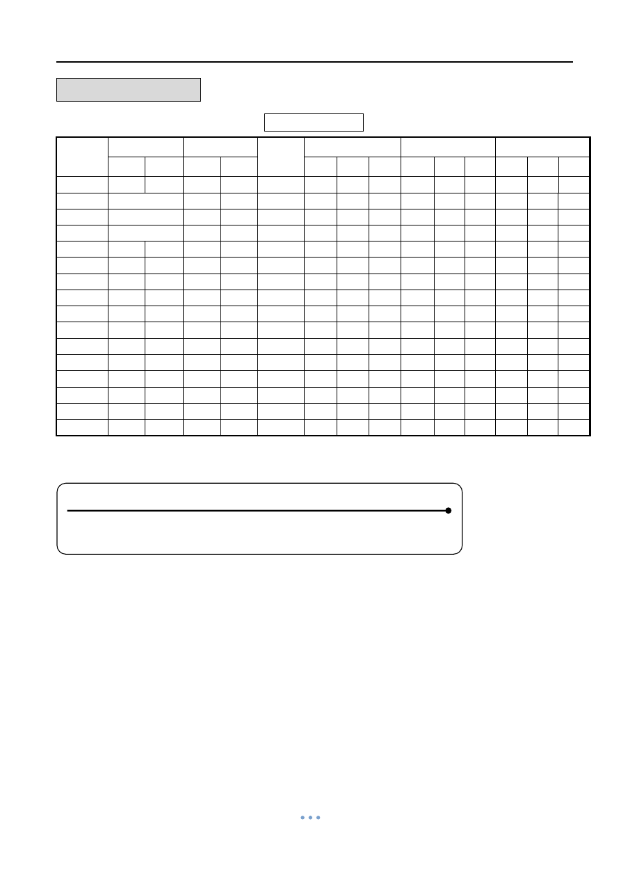
Three Phase
Model
No.
Max Torque Speed (90°) Motor
Power
220V Current
380V Current
440V Current
Nm
lb-in 60Hz 50Hz
Run Start Lock Run Start Lock Run Start Lock
BM-2
120
1063
8 s
10 s
40W
0.8A 1.4A 1.5A 0.4A 0.9A 0.7A 0.4A 0.5A 0.6A
OM-1
-
-
-
-
-
-
-
-
-
-
-
-
-
OM-A
-
-
-
-
-
-
-
-
-
-
-
-
-
OM-A-M
-
-
-
-
-
-
-
-
-
-
-
-
-
OM-2
90
797
15s
17s
40W
0.8A 1.4A 1.5A 0.4A 0.7A 0.7A 0.4A 0.9A 0.6A
OM-3
150
1328
22s
26s
40W
0.8A 1.4A 1.5A 0.4A 0.7A 0.7A 0.4A 0.9A 0.6A
OM-4
400
3542
16s
18s
80W
1.0A 1.8A 2.3A 0.7A 1.3A 1.5A 0.6A 1.4A 1.4A
OM-5
500
4427
22s
25s
80W
1.0A 1.8A 2.3A 0.7A 1.3A 1.5A 0.6A 1.4A 1.4A
OM-6
650
5756
28s
31s
80W
1.0A 1.8A 2.3A 0.7A 1.3A 1.5A 0.6A 1.4A 1.4A
OM-7
1000
8855
46s
55s
120W
0.9A 2.0A 2.2A 0.7A 1.2A 1.4A 0.5A 1.3A 1.3A
OM-8
1500 13282
46s
55s
120W
1.0A 2.4A 2.6A 0.7A 1.5A 1.5A 0.6A 1.2A 1.2A
OM-9
2000 17709
58s
70s
180W
1.3A 3.7A 3.9A 0.7A 2.0A 2.3A 0.7A 2.0A 2.2A
OM-10
2500 22137
58s
70s
180W
1.3A 3.4A 3.9A 0.7A 2.0A 2.4A 0.7A 2.0A 2.2A
OM-11
3000 26564
58s
70s
180W
1.3A 3.5A 3.9A 0.7A 2.0A 2.4A 0.7A 2.0A 2.2A
OM-12
3500 30991
58s
70s
220W
1.5A 4.8A 5.4A 0.9A 2.5A 2.5A 0.8A 2.6A 2.4A
OM-13
4500 39846
80s
95s
220W
1.5A 4.9A 5.4A 1.0A 2.5A 2.5A 0.8A 2.6A 2.4A
NOTE :
Run : Full Load Ampere
Lock : Locked Rotor Ampere

Quarter Turn Actuator 【OM series】
Sun Yeh Ele. Ind. Co., Ltd. | 2013.09
6
STORAGE INFORMATION
Receiving/Inspection
Carefully inspect for shipping damage. Damage to the shipping carton is usually a good
indication that it has received rough handing. Report all damage immediately to the freight
carrier and your seller.
After unpacking the product and information packet, please take care to save the
shipping carton and any packing material in case of product return or replacement. Verify
that the item on the packing list or bill of lading is the same as your own documentation. If
there is any discrepancy, please contact with the seller.
Storage
If the actuator cannot be installed immediately, store it in a dry place, it must be
protected from excess moisture, dust, and weather until you are ready to connect cables.
If the actuator has to be installed but cannot be cabled, please don’t remove the plastic
transit cable entry plugs. When the actuator has to be cabled, it is recommended to replace
to suitable water-proof plugs with IP protection.
LUBRICATION
The gear train has been permanently lubricated at the factory sufficient.

Quarter Turn Actuator 【OM series】
Sun Yeh Ele. Ind. Co., Ltd. | 2013.09
7
INSTALLATION
1. Before mounting actuator, verify that the torque requirement is less than the output
torque of the actuator. (The suggested safety factor is 30% of the max. torque of valve.)
For example :
If the maximum torque of 5
” valve is 80Nm 80 × 1.3(safety factor) =104Nm
104Nm < 150Nm (OM-3) OK!
104Nm > 90Nm (OM-2) NO!
2. Check if the output shaft fits to the stem of valve before inserting into actuator. Please
use mounting plate or adaptor to connect if it does not match.
3. Insert output shaft adaptor into actuator. Make sure it fits satisfactory.
4. Determine that actuator position, open or closed, matches with position of equipment
prior to mounting. Use manual override to change position if necessary.
5. Remove
valve’s manual device and mount on the proper connection.
CAUTION:
Don’t remove any necessary parts for the proper operation of the
valve.
6. Check again that the valve and actuator are in the same position.
7. Install the actuator to valve directly or with mounting kits, then tighten all screws and
nuts.
8. Remove actuator cover.
CAUTION: Be sure power is off at the main power box.
9. Wire actuator using the wiring diagram inside cover.
CAUTION: For the 3-Phase on-off controller actuator, please use the
hand-wheel to turn the actuator to 45 degree before test. If the operating
direction is opposite after supplying power, please change any two of the U,
V, W.
10. Supply power to actuator.
CAUTION: Use remarkable mark warning “there are live circuits that could
cause electrical shock or death”.
11. Make sure if it is needed to calibrate the fully-open or fully-closed position of the actuator.
Refer to the P49~P52 to set the fully -open or fully-closed position and mechanical stops.
12. If the actuator is modulating type, refer to P53~P70 to set the functions.
CAUTION: Turn power off before changing any setting.
13. Replace cover and secure cover screws.
!
!
!
!
!

Quarter Turn Actuator 【OM series】
Sun Yeh Ele. Ind. Co., Ltd. | 2013.09
8
WIRING DIAGRAM
1. MC1 & MC2:Electromagnetic contactor.
2. NFB:No fuse breaker.
3. C.S.:Control switch.
4. C:Capacitor.
5. N:Neutral.
6. L:Live Wire.
7. PE:Protective Earth.
8. O.L.:Over-load relay.
9. H:Heater.
10. LS:Limit switch.
11. TS:Torque switch.
12. Switch(1):Local/Remote Control.
Switch(2):Open/Stop/Close select.
13. Duty cycle (Standard Model) :
BM-2, OM-A, OM-A-M, OM-F, OM-G, OM-1~OM-13:30% duty cycle.
Extended duty cycle :
OM-A, OM-A-M, OM-1~OM-8:75% duty cycle.
OM-9~OM-13:50% duty cycle.
14. LS1:Limit switch for open.
LS2:Limit switch for close.
15. The usage for 2 additional limit switches :
OM-1, OM-A, OM-A-M
LS3 Fully-Open:
Terminal “A” connects to terminal “B”.
LS4 Fully-Closed:
Terminal “A” connects to terminal “E”.
OM-1, OM-A, OM-A-M (Option: MODBUS)
LS3 Fully-Open:
Terminal “A” connects to terminal “C”.
LS4 Fully-Closed:
Terminal “D” connects to terminal “F”.
BM-2, OM-A, OM-AM, OM-F, OM-G, OM-2~OM-13
LS3 Fully-Open:
Terminal “A” connects to terminal “C”.
LS4 Fully-Closed:
Terminal “D” connects to terminal “F”.
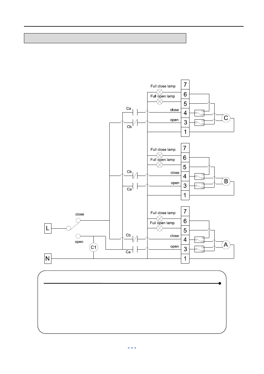
NOTE !
When a set of control wire or switch needs to control two or more
actuators at the same time, please refer to P48 or install the coupling
board.
!
Quarter Turn Actuator 【OM series】
Sun Yeh Ele. Ind. Co., Ltd. | 2013.09
9
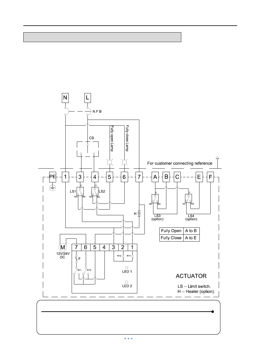
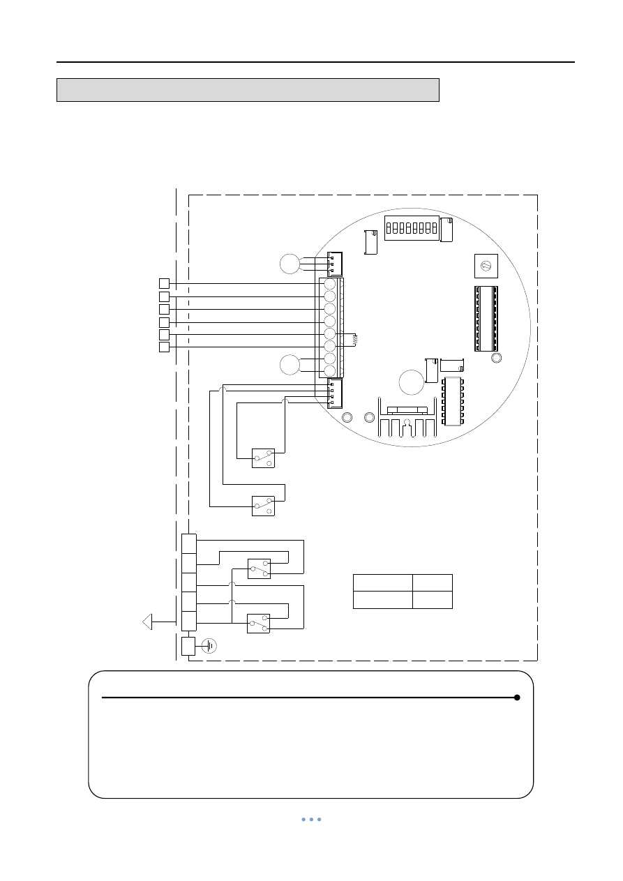
WIRING DIAGRAM
– Quarter Turn Actuator
OM-1 , OM-A , OM-A-M 12V , 24V DC
On-Off Controller
Power Supply
12V / 24V DC
, 220V AC 1-PH
NOTE:
1. “+” connects to #1, “–” connects to #7.
2. “–” connects to #3 for “OPEN”, “–” connects to #4 for “CLOSE”.
3. Using less than 3A current for “A, B, C, E, F”.
4. Using battery to supply power for DC units.
Quarter Turn Actuator 【OM series】
Sun Yeh Ele. Ind. Co., Ltd. | 2013.09
10
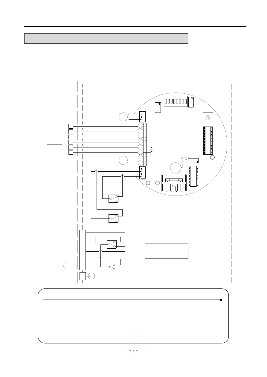
WIRING DIAGRAM
– Quarter Turn Actuator
OM-1 , OM-A , OM-A-M 12V , 24V AC
On-Off Controller
Power Supply
12V / 24V AC
NOTE :
1. “N” connects to #1, “L” connects to #7.
2. “L” connects to #3 for “OPEN”, “L” connects to #4 for “CLOSE”.
3. Using less than 3A current for “A, B, C, E, F”.
Quarter Turn Actuator 【OM series】
Sun Yeh Ele. Ind. Co., Ltd. | 2013.09
11
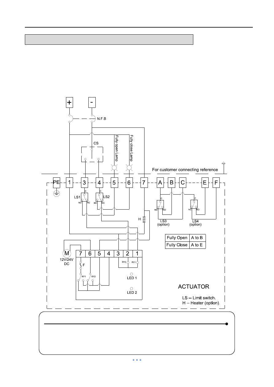
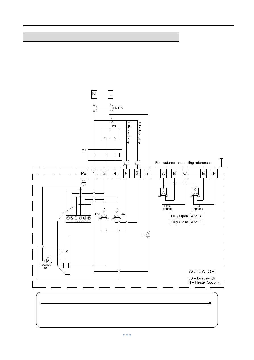
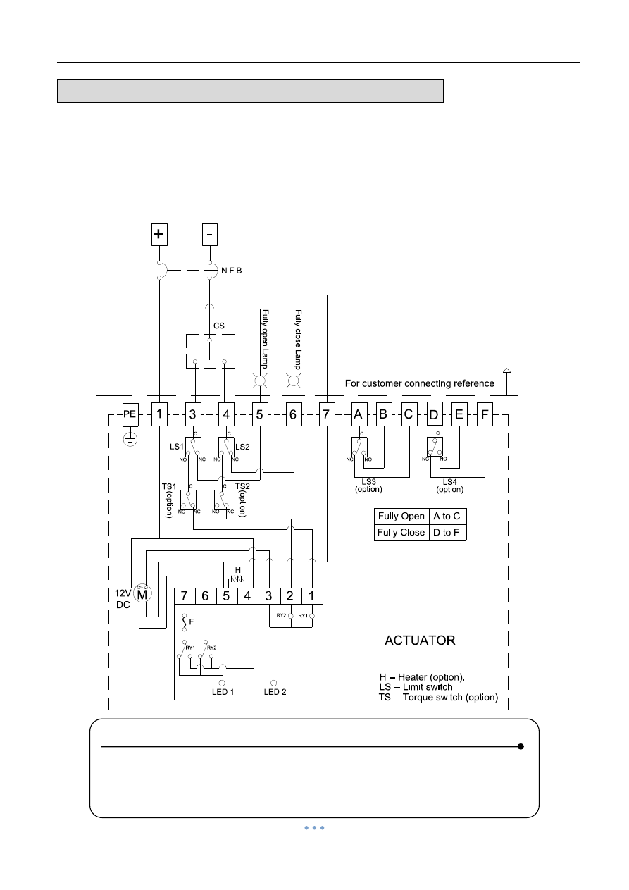
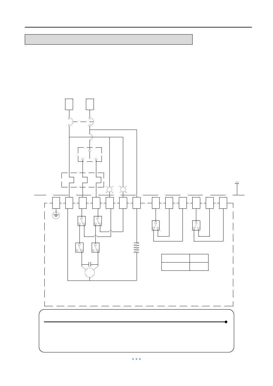
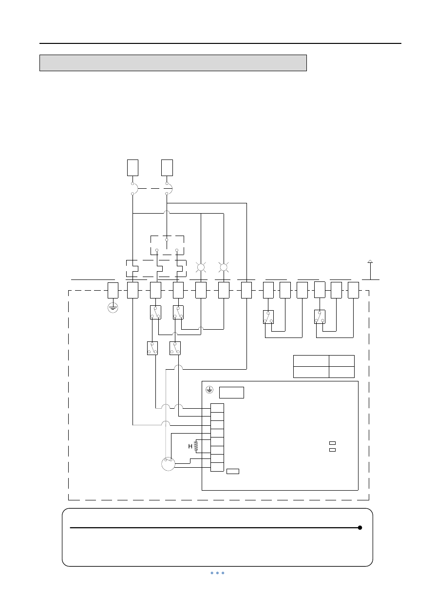
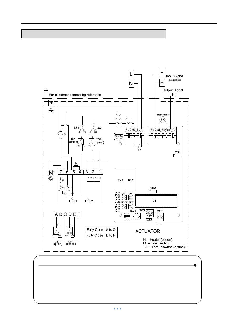
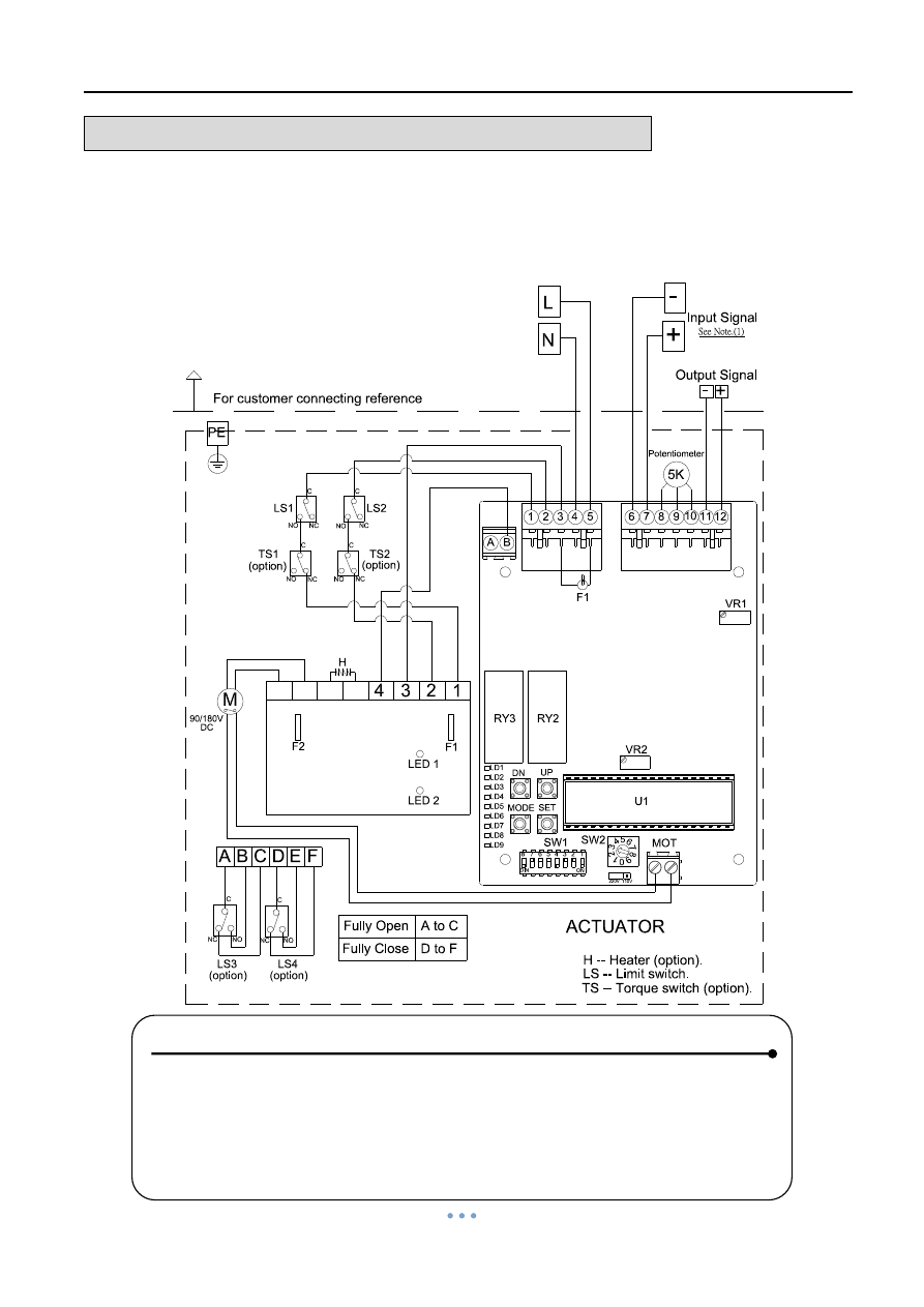
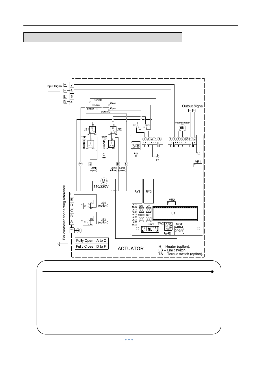
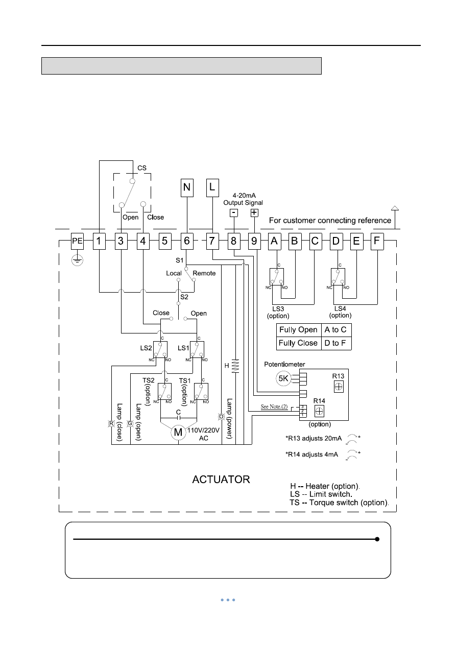
WIRING DIAGRAM
– Quarter Turn Actuator
OM-1 , OM-A , OM-A-M 110V , 220V AC 1-Phase
On-Off Controller
C
NC
NO
C
NO
NC
C
NO
NC
NC
NO
C
C
For customer connecting reference
H -- Heater (option).
Fully Open
Fully Close
A to B
A to E
1
3
4
5
6
7
N
L
110V/220V AC
1-PH
N.F.B
Fu
lly cl
ose
L
a
mp
O.L
ACTUATOR
Fu
lly o
pen
L
a
mp
CS
LS1
LS2
PE
Power supply
On-Off Controller, 30% duty cycle
C
B
A
F
E
LS4
LS3
(option)
(option)
H
M
(3). Using less than 3A current for "A,B,C,E,F".
(2). "L" connects to 3 for "OPEN", "L" connects to 4 for "CLOSE".
(1). "N" connects to 1, "L" connects to 7.
LS -- Limit switch.
Note:
[ OM-1 & OMA & OM-A-M 110V/220V AC 1-Phase ]
ACTUATOR
110V/220V
AC
Power Supply
110V / 220V AC
NOTE :
1.
“N” connects to #1, “L” connects to #7.
2.
“L” connects to #3 for “OPEN”, “L” connects to #4 for “CLOSE”.
3. Using less than 3
A current for “A, B, C, E, F”.
Quarter Turn Actuator 【OM series】
Sun Yeh Ele. Ind. Co., Ltd. | 2013.09
12
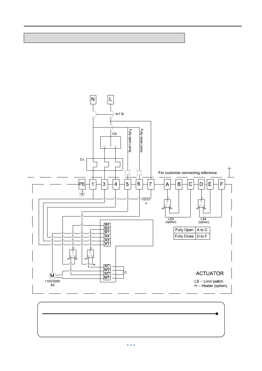
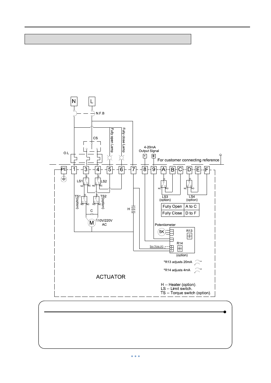
WIRING DIAGRAM
– Quarter Turn Actuator
OM-1 , OM-A , OM-A-M 110V , 220V AC 1-Phase
On-Off Controller , 75% duty cycle
LS -- Limit switch.
Note:
H -- Heater (option).
DC
Fully Open
Fully Close
A to B
A to E
On-Off Controller , 75% duty cycle
ACTUATOR
LED 1
C
NC
NO
C
NC
NO
RY2
RY1
RY2
RY1
24V
H
For customer connecting reference
1-PH
LED 2
(3). Using less than 3A current for "A,B,C,E,F".
(2). "L" connects to 3 for "OPEN", "L" connects to 4 for "CLOSE"
(1). "N" connects to 1, "L" connects to 7.
1
3
4
7
A
B
C
E
F
N
L
Power supply
110V/220V AC
N.F.B
LS3
LS4
M
(option)
(option)
PE
LS2
LS1
7
6
5
3
2
1
5
6
F
ul
ly
o
pen Lam
p
F
ul
ly
c
los
e
Lam
p
[ OM-1 & OM-A & OM-A-M 110V/220V AC 1-Phase ]
CS
C
C
NO
NC
NO
NC
Power Supply
110V / 220V AC
NOTE :
1. “N” connects to #1, “L” connects to #7.
2. “L” connects to #3 for “OPEN”, “L” connects to #4 for “CLOSE”.
3. Using less than 3A current for “A, B, C, E, F”.
Quarter Turn Actuator 【OM series】
Sun Yeh Ele. Ind. Co., Ltd. | 2013.09
13
WIRING DIAGRAM
– Quarter Turn Actuator
OM-1 , OM-A , OM-A-M 110V , 220V AC 1-Phase
On-Off Controller , Coupling Board
Power Supply
110V / 220V AC
NOTE :
1.
“N” connects to #1, “L” connects to #7.
2.
“L” connects to #3 for “OPEN”, “L” connects to #4 for “CLOSE”.
3. Using less than 3
A current for “A, B, C, E, F”.
Quarter Turn Actuator 【OM series】
Sun Yeh Ele. Ind. Co., Ltd. | 2013.09
14
WIRING DIAGRAM
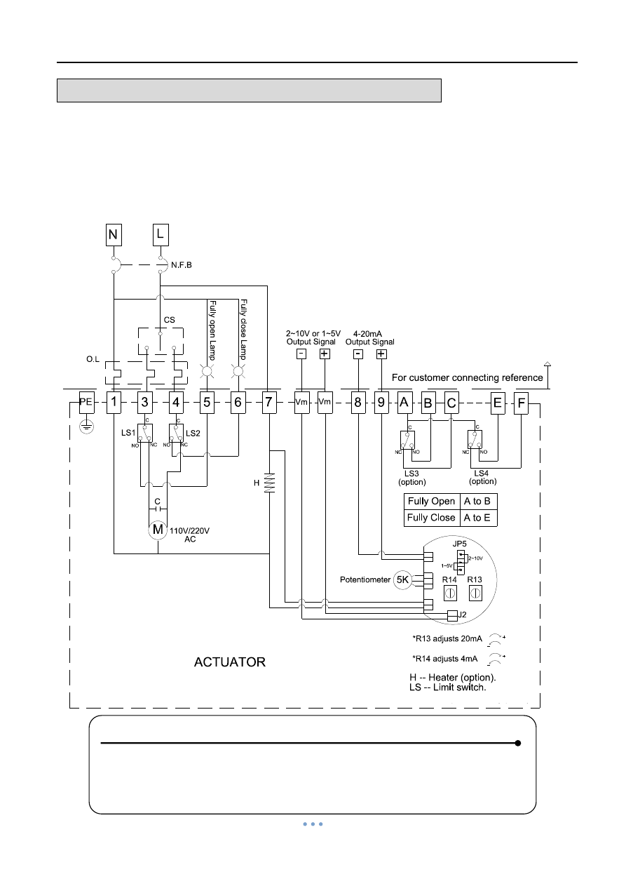
– Quarter Turn Actuator
OM-1 , OM-A , OM-A-M 110V , 220V AC 1-Phase
On-Off Controller , Analog Signal Output
Power Supply
110V / 220V AC
NOTE:
1.
“N” connects to #1, “L” connects to #7.
2.
“L” connects to #3 for “OPEN”, “–” connects to #4 for “CLOSE”.
3. Using less than 3
A current for “A, B, C, E, F”.
4. JP5:2~10V or 1~5V output mode;J2:2~10V or 1~5V output signal.
Quarter Turn Actuator 【OM series】
Sun Yeh Ele. Ind. Co., Ltd. | 2013.09
15
WIRING DIAGRAM
– Quarter Turn Actuator
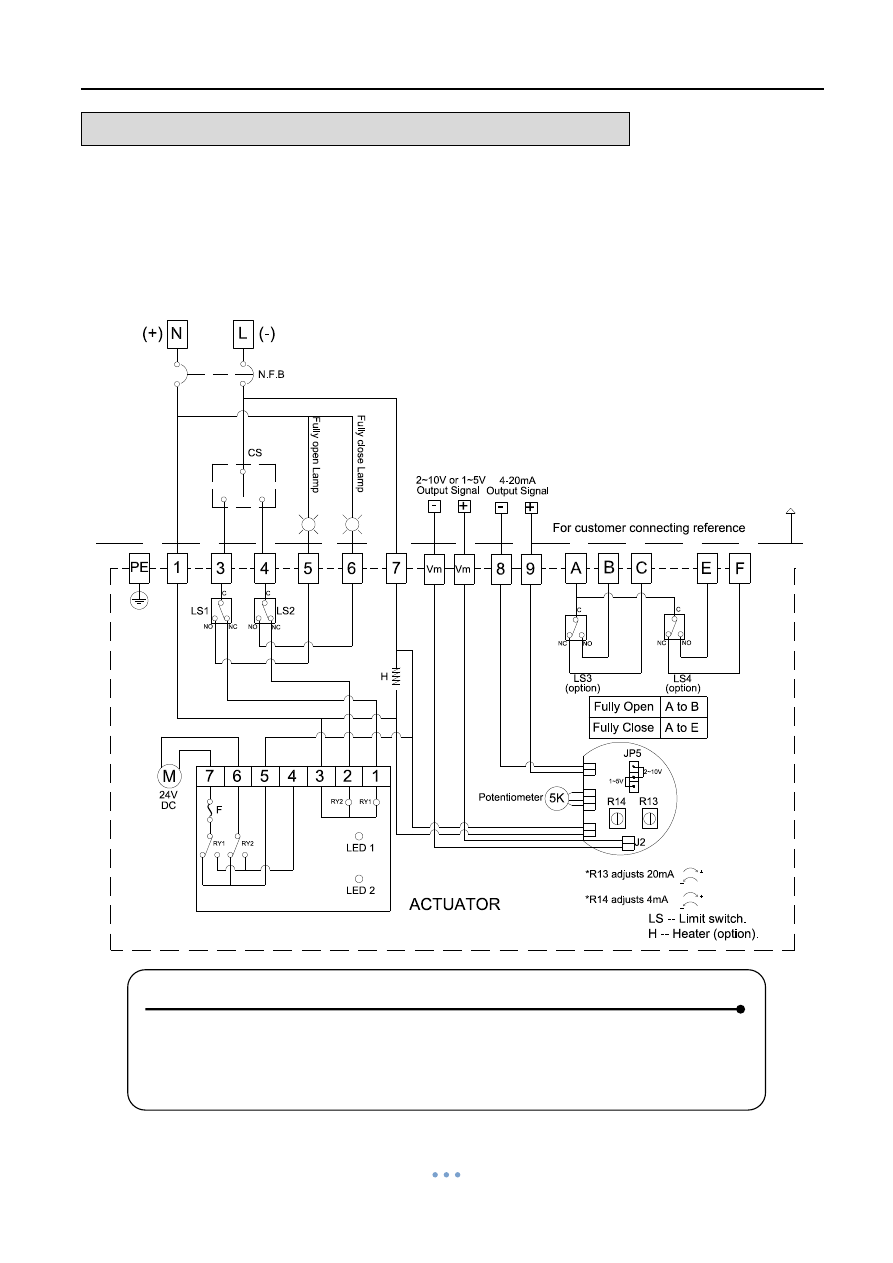
OM-1 , OM-A , OM-A-M 24V AC/DC
On-Off Controller , Analog Signal Output
Power Supply
24V AC/DC
NOTE:
1.
“N” connects to #1, “L” connects to #7.
2.
“L” connects to #3 for “OPEN”, “–” connects to #4 for “CLOSE”.
3. Using less than 3
A current for “A, B, C, E, F”.
4. JP5:2~10V or 1~5V output mode;J2:2~10V or 1~5V output signal.
Quarter Turn Actuator 【OM series】
Sun Yeh Ele. Ind. Co., Ltd. | 2013.09
16
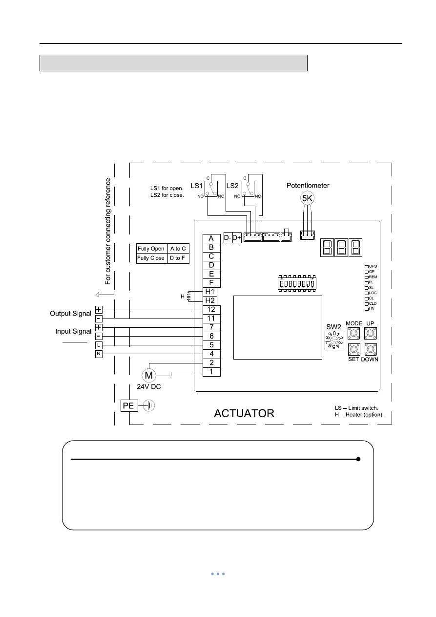
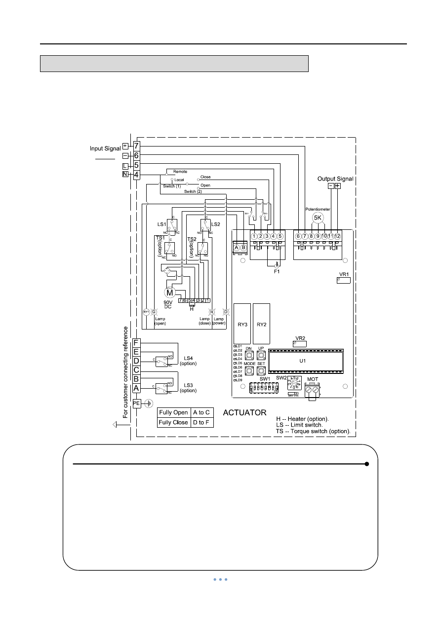
WIRING DIAGRAM
– Quarter Turn Actuator
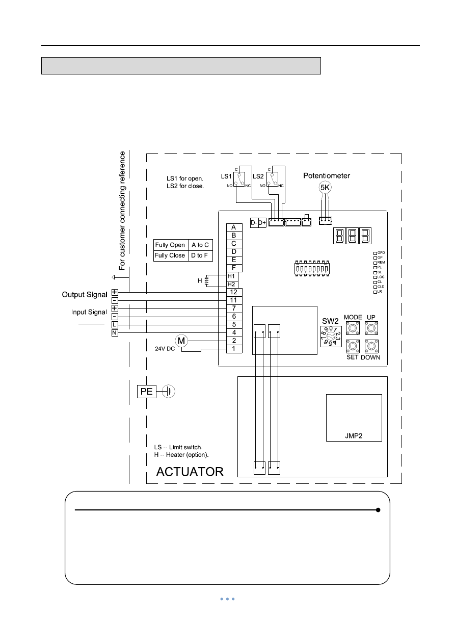
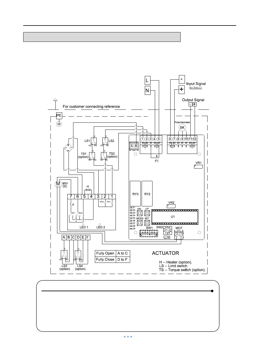
OM-1 , OM-A , OM-A-M 24V DC
Modulating Controller
Fully Open
Fully Close
A to B
A to E
(option)
LS3
(option)
Note:
(1). Modulating Board
(it is suggested to use the shielding wire and its length should not exceed 30m.)
Output Signal : 4-20mA, 2-10V
H -- Heater (option).
H
U4
1
2
4
5
6
7
11
12
VR1
P1
P2
DIP-SW VR2
SW1
VR51
VR52
LD3
U1
U7
LDG
LDR
ON
DIP
1 2 3 4 5 6 7 8
1
0
9
8
7
6
5
[ OM-1 & OM-A & OM-A-M 24V DC ]
5K
M
+
Output Signal
24VDC
Input Signal
LS4
A
C
NC
NO
C
B
C
E
F
NC
NO
-
+
+
C
NC
C
NC
LS1
LS2
NO
NO
For c
us
to
mer c
onn
ec
ti
n
g
r
e
fe
re
n
ce
-
-
Power supply
4
3
2
Input Signal : 4-20mA, 1-5V, 2-10V
See Note.(1)
LS -- Limit switch.
Modulating Controller, 75% duty cycle
ACTUATOR
(2). Using less than 3A current for switches "A,B,C,E,F".
(3). Using battery to supply power for DC units.
PE
24V
DC
Potentiometer
NOTE :
1. Modulating Board
a. Input Signal:4~20mA, 1~5V, 2~10V
(It is suggested to use the shielding wire and its length should not
exceed 30m.)
b. Output Signal:4~20mA, 2~10V
2. Using less than 3
A current for “A, B, C, E, F”.
3. Using battery to supply power for DC units.
Power Supply
24V DC
Quarter Turn Actuator 【OM series】
Sun Yeh Ele. Ind. Co., Ltd. | 2013.09
17
WIRING DIAGRAM
– Quarter Turn Actuator
OM-1 , OM-A , OM-A-M 24V AC
Modulating Controller
Input Signal : 4-20mA, 1-5V, 2-10V
LS -- Limit switch.
See Note.(1)
Modulating Controller, 75% duty cycle
ACTUATOR
(2). Using less than 3A current for "A,B,C,E,F".
For cu
stom
er co
nn
ecti
n
g
re
fe
re
n
c
e
PE
24V
DC
Potentiometer
[ OM-1 & OM-A & OM-A-M 24V AC ]
5K
M
Output Signal
24VAC
Input Signal
LS4
A
C
NC
NO
C
B
C
E
F
NC
NO
+
+
-
C
NC
C
NC
LS1
LS2
NO
NO
-
L
N
Power supply
Note:
(1). Modulating Board
( it is suggested to use the shielding wire and its length should not exceed 30m.)
Output Signal : 4-20mA, 2-10V
H -- Heater (option).
(option)
LS3
(option)
Fully Open
Fully Close
A to B
A to E
1
2
4
5
6
7
11
12
VR1
P1
P2
DIP-SW VR2
SW1
VR51
VR52
LD3
U1
U7
LDG
LDR
U4
H
ON
DIP
1 2 3 4 5 6 7 8
1
0
9
8
7
6
5
4
3
2
Power Supply
24V AC
NOTE :
1. Modulating Board
a. Input Signal:4~20mA, 1~5V, 2~10V
(It is suggested to use the shielding wire and its length should not
exceed 30m.)
b. Output Signal:4~20mA, 2~10V
2. Using less than 3
A current for “A, B, C, E, F”.
Quarter Turn Actuator 【OM series】
Sun Yeh Ele. Ind. Co., Ltd. | 2013.09
18
WIRING DIAGRAM
– Quarter Turn Actuator
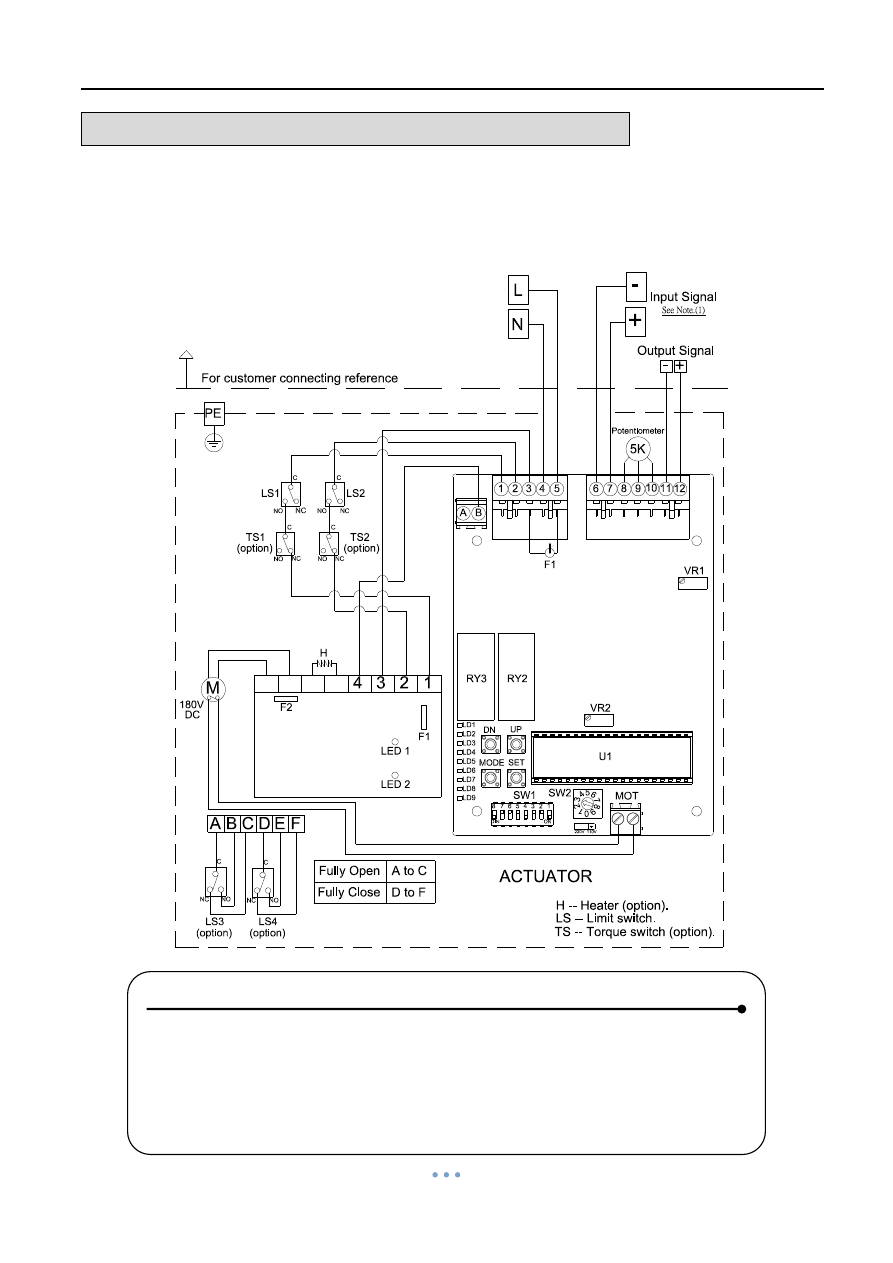
OM-1 , OM-A , OM-A-M 110V , 220V AC 1-Phase
Modulating Controller
[ OM-1 & OM-A & OM-A-M 110V/220V AC 1-Phase ]
5K
M
Output Signal
110V/220V AC
Input Signal
LS4
A
C
NC
NO
C
B
C
E
F
NC
NO
N
-
+
+
-
C
NC
C
NC
LS1
LS2
NO
NO
L
Power supply
H -- Heater (option).
Input Signal : 4-20mA, 1-5V, 2-10V
LS -- Limit switch.
See Note.(1)
1-PH
Modulating Controller, 75% duty cycle
ACTUATOR
(2). Using less than 3A current for "A,B,C,E,F".
1
2
4
5
6
7
11
12
VR1
P1
P2
DIP-SW VR2
SW1
VR51
VR52
LD3
U1
U7
LDG
LDR
U4
H
ON
DIP
1 2 3 4 5 6 7 8
1
0
9
8
7
6
5
4
3
2
For cu
stom
er co
nn
ecti
n
g
re
fe
re
n
c
e
PE
24V
DC
Potentiometer
Note:
(1). Modulating Board
(it is suggested to use the shielding wire and its length should not exceed 30m.)
Output Signal : 4-20mA, 2-10V
Fully Open
Fully Close
A to B
A to E
(option)
LS3
(option)
Power Supply
110V / 220 AC
NOTE:
1. Modulating Board
a. Input Signal:4~20mA, 1~5V, 2~10V
(It is suggested to use the shielding wire and its length should not
exceed 30m.)
b. Output Signal:4~20mA, 2~10V
2.
Using less than 3A current for “A, B, C, E, F”.
See Note (1)
Quarter Turn Actuator 【OM series】
Sun Yeh Ele. Ind. Co., Ltd. | 2013.09
19
WIRING DIAGRAM
– Quarter Turn Actuator
OM-1 , OM-A , OM-A-M 24V AC
Modulating Controller , MODBUS
Power Supply
24V AC
NOTE:
1. Modulating Board
a. Input Signal:4~20mA, 1~5V, 2~10V
(It is suggested to use the shielding wire and its length should not
exceed 30m.)
b. Output Signal:4~20mA, 2~10V
2.
Using less than 3A current for “A, B, C, E, F”.
See Note (1)
Quarter Turn Actuator 【OM series】
Sun Yeh Ele. Ind. Co., Ltd. | 2013.09
20
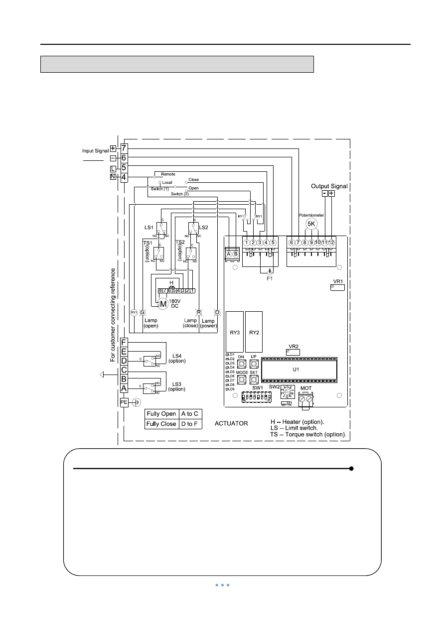
WIRING DIAGRAM
– Quarter Turn Actuator
OM-1 , OM-A , OM-A-M 24V DC
Modulating Controller , MODBUS
Power Supply
24V DC
NOTE :
1. Modulating Board
a. Input Signal:4~20mA, 1~5V, 2~10V
(It is suggested to use the shielding wire and its length should not
exceed 30m.)
b. Output Signal:4~20mA, 2~10V
2.
Using less than 3A current for “A, B, C, E, F”.
3. Using battery to supply power for DC units.
See Note (1)
Quarter Turn Actuator 【OM series】
Sun Yeh Ele. Ind. Co., Ltd. | 2013.09
21
WIRING DIAGRAM
– Quarter Turn Actuator
OM-1 , OM-A , OM-A-M 110V , 220V AC 1-Phase
Modulating Controller , MODBUS
Power Supply
110V / 220V AC
NOTE:
1. Modulating Board
a. Input Signal:4~20mA, 1~5V, 2~10V
(It is suggested to use the shielding wire and its length should not
exceed 30m.)
b. Output Signal:4~20mA, 2~10V
2. Using less than 3A
current for “A, B, C, E, F”.
See Note (1)
Quarter Turn Actuator 【OM series】
Sun Yeh Ele. Ind. Co., Ltd. | 2013.09
22
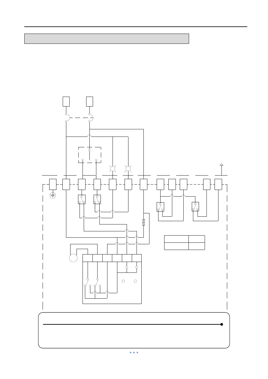
WIRING DIAGRAM
– Quarter Turn Actuator
OM-2 ~ OM-6 12V DC
OM-2 ~ OM-12 , OM-F , OM-G 24V DC
On-Off Controller
1
3
4
7
A
B
C
E
F
+
-
Power supply
12V/24V DC
N.F.B
LS3
LS4
M
Note:
(1). "+" connects to 1, "-" connects to 7.
(2). "-" connects to 3 for "OPEN", "-" connects to 4 for "CLOSE"
(3). Using less than 5A current for "A,B,C,E,F".
LS -- Limit switch.
(option)
(option)
TS1
TS -- Torque switch (option).
(4). Using battery to supply power for DC units.
D
PE
LS2
LS1
7
6
5
4
3
2
1
5
6
Ful
ly
open
L
a
m
p
Ful
ly
c
los
e
L
a
m
p
[ OM-2 ~ OM-6 12V DC ]
CS
C
C
NO
NC
NO
NC
C
C
NC
LED 1
LED 2
C
NC
NO
C
NC
NO
RY2
RY1
RY2
F
NC
RY1
(opti
on
)
TS2
(opti
on
)
NO
NO
H
H -- Heater (option).
For customer connecting reference
Fully Open
Fully Close
A to C
D to F
[ OM-2 ~ OM-12, OM-G, OM-F 24V DC ]
On-Off Controller, 75% duty cycle
ACTUATOR
12V/24V
DC
Power Supply
12V / 24V DC
NOTE:
1.
“+” connects to #1, “–” connects to #7.
2.
“–” connects to #3 for “OPEN”, “–” connects to #4 for “CLOSE”.
3.
Using less than 5A current for “A, B, C, D, E, F”.
4. Using battery to supply power for DC units.
Quarter Turn Actuator 【OM series】
Sun Yeh Ele. Ind. Co., Ltd. | 2013.09
23
WIRING DIAGRAM
– Quarter Turn Actuator
OM-2 ~ OM-6 12V AC
OM-2 ~ OM-12 , OM-F , OM-G 24V AC
On-Off Controller
1
3
4
7
A
B
C
E
F
N
L
Power supply
12V/24V AC
N.F.B
LS3
LS4
Note:
(1). "N" connects to 1, "L" connects to 7.
(2). "L" connects to 3 for "OPEN", "L" connects to 4 for "CLOSE"
(3). Using less than 5A current for "A,B,C,D,E,F".
(option)
(option)
TS1
TS2
D
PE
LS2
LS1
(opti
on)
(opti
on)
5
6
+
-
Full
y
open Lamp
Ful
ly
c
lose
La
mp
[ OM-2 ~ OM-6 12V AC ]
CS
C
NO
NC
C
M
7
6
5
4
3
2
1
12V/24V
LED 1
LED 2
RY2
RY1
H
RY2
F
C
NO
NC
NC
NC
C
RY1
C
NC
NO
C
NC
NO
NO
NO
For customer connecting reference
Fully Open
Fully Close
A to C
D to F
DC
[ OM-2 ~ OM-12, OM-G, OM-F 24V AC ]
LS -- Limit switch.
TS -- Torque switch (option).
H -- Heater (option).
On-Off Controller, 75% duty cycle
ACTUATOR
Power Supply
12V / 24V AC
NOTE :
1.
“N” connects to #1, “L” connects to #7.
2.
“L” connects to #3 for “OPEN”, “L” connects to #4 for “CLOSE”.
3.
Using less than 5A current for “A, B, C, D, E, F”.
Quarter Turn Actuator 【OM series】
Sun Yeh Ele. Ind. Co., Ltd. | 2013.09
24
WIRING DIAGRAM
– Quarter Turn Actuator
OM-7 ~ OM-10 12V DC
On-Off Controller
Power Supply
12V DC
NOTE:
1.
“+” connects to #1, “–” connects to #7.
2.
“–” connects to #3 for “OPEN”, “–” connects to #4 for “CLOSE”.
3.
Using less than 5A current for “A, B, C, D, E, F”.
4. Using battery to supply power for DC units.
Quarter Turn Actuator 【OM series】
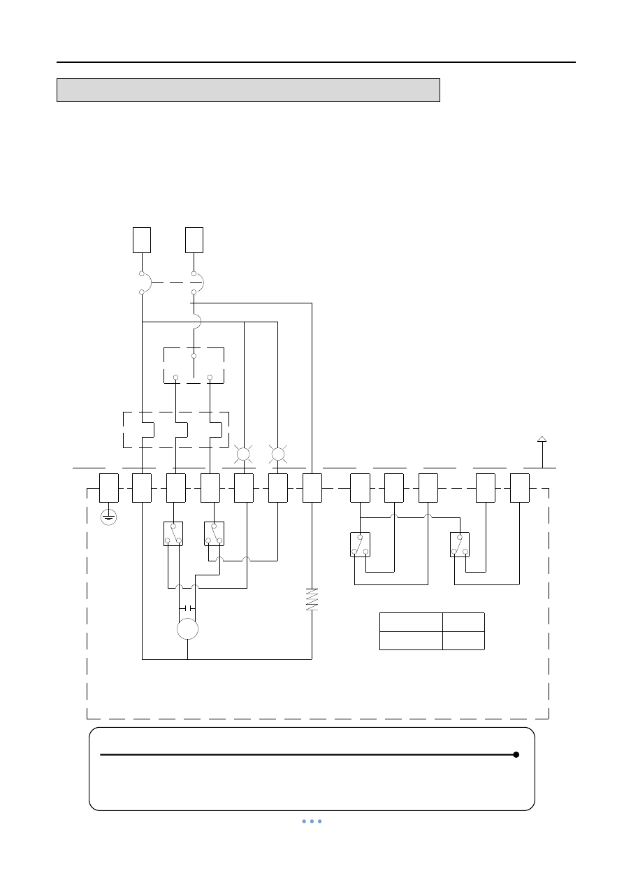
Sun Yeh Ele. Ind. Co., Ltd. | 2013.09
25
WIRING DIAGRAM
– Quarter Turn Actuator
BM-2 , OM-2~OM-13 , OM-F , OM-G 110V , 220V AC 1-Phase
On-Off Controller
On-Off Controller, 30% duty cycle
110V/220V
AC
[ BM-2, OM-2~OM~13, OM-G, OM-F 110V/220V AC 1-Phase ]
C
NC
NO
C
NO
NC
C
NO
NC
NC
NO
C
D
TS1
C
TS2
C
NC
NC
Fully Open
Fully Close
A to C
D to F
NO
NO
For customer connecting reference
C
(1). "N" connects to 1, "L" connects to 7.
(option)
(option)
(option)
(option)
LS -- Limit switch.
TS -- Torque switch (option).
H -- Heater (option).
1
3
4
5
6
7
N
L
110V/220V AC
1-PH
N.F.B
Ful
ly
cl
ose L
a
mp
O.L
ACTUATOR
Ful
ly
open L
a
mp
CS
LS1
LS2
PE
Power supply
C
B
A
F
E
LS4
LS3
H
M
(3). Using less than 5A current for "A,B,C,D,E,F".
(2). "L" connects to 3 for "OPEN", "L" connects to 4 for "CLOSE".
(4). BM-2 could not install torque switches.
Note:
Power Supply
110V / 220V AC
NOTE :
1.
“N” connects to #1, “L” connects to #7.
2.
“L” connects to #3 for “OPEN”, “L” connects to #4 for “CLOSE”.
3.
Using less than 5A current for “A, B, C, D, E, F”.
4. BM-2 could not install torque switches.
Quarter Turn Actuator 【OM series】
Sun Yeh Ele. Ind. Co., Ltd. | 2013.09
26
WIRING DIAGRAM
– Quarter Turn Actuator
OM-2 ~ OM-13 , OM-F , OM-G 110V , 220V AC 1-Phase
On-Off Controller , Coupling Board
Power Supply
110V / 220V AC
NOTE :
1.
“N” connects to #1, “L” connects to #7.
2.
“L” connects to #3 for “OPEN”, “L” connects to #4 for “CLOSE”.
3.
Using less than 5A current for “A, B, C, D, E, F”.
Quarter Turn Actuator 【OM series】
Sun Yeh Ele. Ind. Co., Ltd. | 2013.09
27
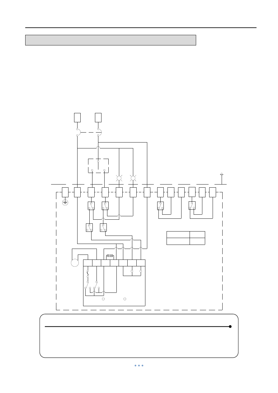
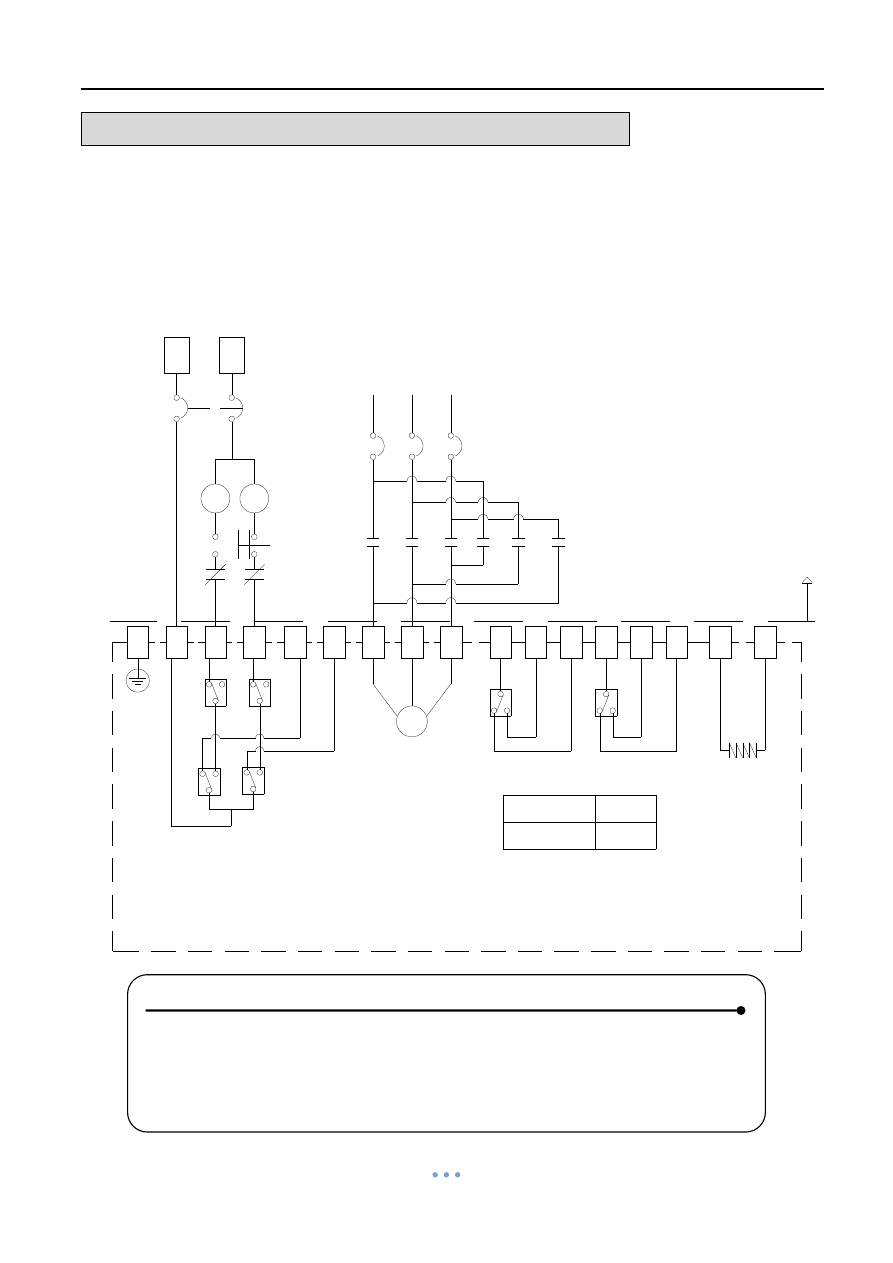
WIRING DIAGRAM
– Quarter Turn Actuator
BM-2 , OM-2 ~ OM-13 220V , 380V , 440V AC 3-Phase
On-Off Controller
N.F.B
[ BM-2, OM-2 ~ OM-13 220V, 380V, 440V AC 3-Phase ]
MC2
MC1-a
MC1-a
MC2-a
MC2-a
MC2-a
6
5
C
NC
NO
C
NC
NC
C
NC
NO NC
NO
LS2
C
C
C
NC
NO
NO
NO
For customer connecting reference
8
9
Note:
(1).BM-2 could not install torque switches.
Fully Open
Fully Close
A to C
D to F
LS4
(option)
1
3
4
U
V
W
A
B C D
E
F
N
L
220V/380V/440V
3-PH
LS3
H
ACTUATOR
MC1
MC2-b
MC1-b
OPEN
CLOSE
M
R
S
T
N.F.B
MC1-a
TS1
TS2
LS1
PE
(opt
io
n)
(opt
io
n)
(option)
Power supply
LS -- Limit switch.
TS -- Torque switch (option).
H -- Heater (option).
(2).Using the hand-wheel to turn the actuator to 45 degree before test.
If the operating direction is opposite, please change any two of U, V, W.
(3).Using less than 5A current for "A,B,C,E,F".
On-Off Controller, 30% duty cycle
220V/380V/440V
AC
Power Supply
220V / 380V / 440V AC 3-PH
NOTE :
1. Using the hand-wheel to turn the actuator to 45 degree before test.
If the operating direction is opposite after supplying power, please
change any two of the U, V, W.
2.
Using less than 5A current for “A, B, C, D, E, F”.
3. BM-2 could not install torque switches.
“A, B, C, D, E, F”.
1.

Quarter Turn Actuator 【OM series】
Sun Yeh Ele. Ind. Co., Ltd. | 2013.09
28
WIRING DIAGRAM
– Quarter Turn Actuator
OM-2 ~ OM-8 110V , 220V AC 1-Phase
On-Off Controller , 75% duty cycle
C
C
NO
NC
NO
NC
C
C
NC
C
NC
NO
C
NC
NO
NC
(opti
on)
(opti
on)
M
[ OM-2~OM-8 110V, 220V AC 1-Phase ]
Power supply
O.L
NO
NO
90V/180V
Fully Open
Fully Close
A to C
D to F
For customer connecting reference
DC
Note:
(1). "N" connects to 1, "L" connects to 7.
(2). "L" connects to 3 for "OPEN", "L" connects to 4 for "CLOSE".
(3). Using less than 5A current for "A,B,C,D,E,F".
LS -- Limit switch.
TS -- Torque switch (option).
H -- Heater (option).
On-Off Controller, 75% duty cycle
ACTUATOR
1
3
4
7
A
B
C
E
F
N
L
110V/220V AC
1 - PH
N.F.B
LS3
LS4
(option)
(option)
TS1
TS2
D
PE
LS2
LS1
5
6
Ful
ly ope
n La
mp
Ful
ly cl
os
e
La
mp
CS
1
2
3
4
F1
F2
OPEN
CLOSE
Power Supply
110V / 220V AC
NOTE :
1.
“N” connects to #1, “L” connects to #7.
2.
“L” connects to #3 for “OPEN”, “L” connects to #4 for “CLOSE”.
3.
Using less than 5A current for “A, B, C, D, E, F”.
Quarter Turn Actuator 【OM series】
Sun Yeh Ele. Ind. Co., Ltd. | 2013.09
29
WIRING DIAGRAM
– Quarter Turn Actuator
OM-9 ~ OM-13 110V AC 1-Phase
On-Off Controller , 50% duty cycle
1
3
4
7
A
B
C
E
F
N
L
Power supply
110V AC
N.F.B
LS3
LS4
(option)
(option)
TS1
TS2
D
PE
LS2
LS1
(option)
(option)
5
6
+
-
F
u
lly op
en
L
a
m
p
F
u
lly close L
a
m
p
[ OM-9 ~ OM-13 110V AC 1-Phase ]
CS
Fully Open
Fully Close
A to C
D to F
DC
Note:
(1). "N" connects to 1, "L" connects to 7.
(2). "L" connects to 3 for "OPEN", "L" connects to 4 for "CLOSE".
(3). Using less than 5A current for "A,B,C,D,E,F".
1-PH
LS -- Limit switch.
TS -- Torque switch (option).
H -- Heater (option).
On-Off Controller, 50% duty cycle
ACTUATOR
C
NO
NC
C
M
7
6
5
4
3
2
1
90V
LED 1
LED 2
RY2
RY1
H
RY2
F
C
NO
NC
NC
NC
C
RY1
C
NC
NO
C
NC
NO
NO
For customer connecting reference
NO
Power Supply
110V AC
NOTE :
1.
“N” connects to #1, “L” connects to #7.
2.
“L” connects to #3 for “OPEN”, “L” connects to #4 for “CLOSE”.
3.
Using less than 5A current for “A, B, C, D, E, F”.
Quarter Turn Actuator 【OM series】
Sun Yeh Ele. Ind. Co., Ltd. | 2013.09
30
WIRING DIAGRAM
– Quarter Turn Actuator
OM-9 ~ OM-13 220V AC 1-Phase
On-Off Controller , 50% duty cycle
C
C
NO
NC
NO
NC
C
C
NC
C
NC
NO
C
NC
NO
NC
(opti
on)
(opti
on)
M
[ OM-9~OM-13 220V AC 1-Phase ]
Power supply
O.L
NO
NO
180V
Fully Open
Fully Close
A to C
D to F
For customer connecting reference
DC
Note:
(1). "N" connects to 1, "L" connects to 7.
(2). "L" connects to 3 for "OPEN", "L" connects to 4 for "CLOSE".
(3). Using less than 5A current for "A,B,C,D,E,F".
LS -- Limit switch.
TS -- Torque switch (option).
H -- Heater (option).
On-Off Controller, 50% duty cycle
ACTUATOR
1
3
4
7
A
B
C
E
F
N
L
220V AC
1 - PH
N.F.B
LS3
LS4
(option)
(option)
TS1
TS2
D
PE
LS2
LS1
5
6
Ful
ly ope
n La
mp
Ful
ly cl
os
e
La
mp
CS
1
2
3
4
F1
F2
OPEN
CLOSE
Power Supply
220V AC
NOTE :
1.
“N” connects to #1, “L” connects to #7.
2.
“L” connects to #3 for “OPEN”, “L” connects to #4 for “CLOSE”.
3.
Using less than 5A current for “A, B, C, D, E, F”.
Quarter Turn Actuator 【OM series】
Sun Yeh Ele. Ind. Co., Ltd. | 2013.09
31
WIRING DIAGRAM
– Quarter Turn Actuator
OM-2 ~ OM-13 110V , 220V AC 1-Phase
On-Off Controller , Analog Signal Output
Power Supply
110V / 220V AC
NOTE:
1.
“N” connects to #1, “ L ” connects to #7.
2.
“L” connects to #3 for “OPEN”, “L” connects to #4 for “CLOSE”.
3.
Using less than 5A current for “A, B, C, D, E, F”.
4. If the control power is 220V AC, N & L connect to #1 & #3.
If the control power is 110V AC, N & L connect to #1 & #2 or #2 & #3.
Quarter Turn Actuator 【OM series】
Sun Yeh Ele. Ind. Co., Ltd. | 2013.09
32
WIRING DIAGRAM
– Quarter Turn Actuator
OM-2 ~ OM-13 220V , 380V , 440V AC 3-Phase
On-Off Controller , Analog Signal Output
Power Supply
220V / 380V / 440V AC 3-PH
NOTE:
1. If the control power is 220V AC, N & L connect to #1 & #3.
If the control power is 110V AC, N & L connect to #1 & #2 or #2 & #3.
2. Using the hand-wheel to turn the actuator to 45 degree before test. If the
operating direction is opposite after supplying power, please change any
two of the U, V, W.
3.
Using less than 5A current for “A, B, C, D, E, F”.
“A, B, C, D, E, F”.
Quarter Turn Actuator 【OM series】
Sun Yeh Ele. Ind. Co., Ltd. | 2013.09
33
WIRING DIAGRAM
– Quarter Turn Actuator
OM-2 ~ OM-6 12V DC
OM-2 ~ OM-12 , OM-F , OM-G 24V DC
Modulating Controller
Power Supply
12V / 24V DC
NOTE:
1. Modulating Board
a. Input Signal:4~20mA, 1~5V, 2~10V
(It is suggested to use the shielding wire and its length should not
exceed 30m.)
b. Output Signal:4~20mA, 2~10V
2.
Using less than 5A current for “A, B, C, D, E, F”.
3. Using battery to supply power for DC units.
Quarter Turn Actuator 【OM series】
Sun Yeh Ele. Ind. Co., Ltd. | 2013.09
34
WIRING DIAGRAM
– Quarter Turn Actuator
OM-2 ~ OM-12 , OM-F , OM-G 24V AC
Modulating Controller
Power Supply
24V AC
NOTE:
1. Modulating Board
a. Input Signal:4~20mA, 1~5V, 2~10V
(It is suggested to use the shielding wire and its length should not
exceed 30m.)
b. Output Signal:4~20mA, 2~10V
2. Using less than 5
A current for “A, B, C, D, E, F”.
Quarter Turn Actuator 【OM series】
Sun Yeh Ele. Ind. Co., Ltd. | 2013.09
35
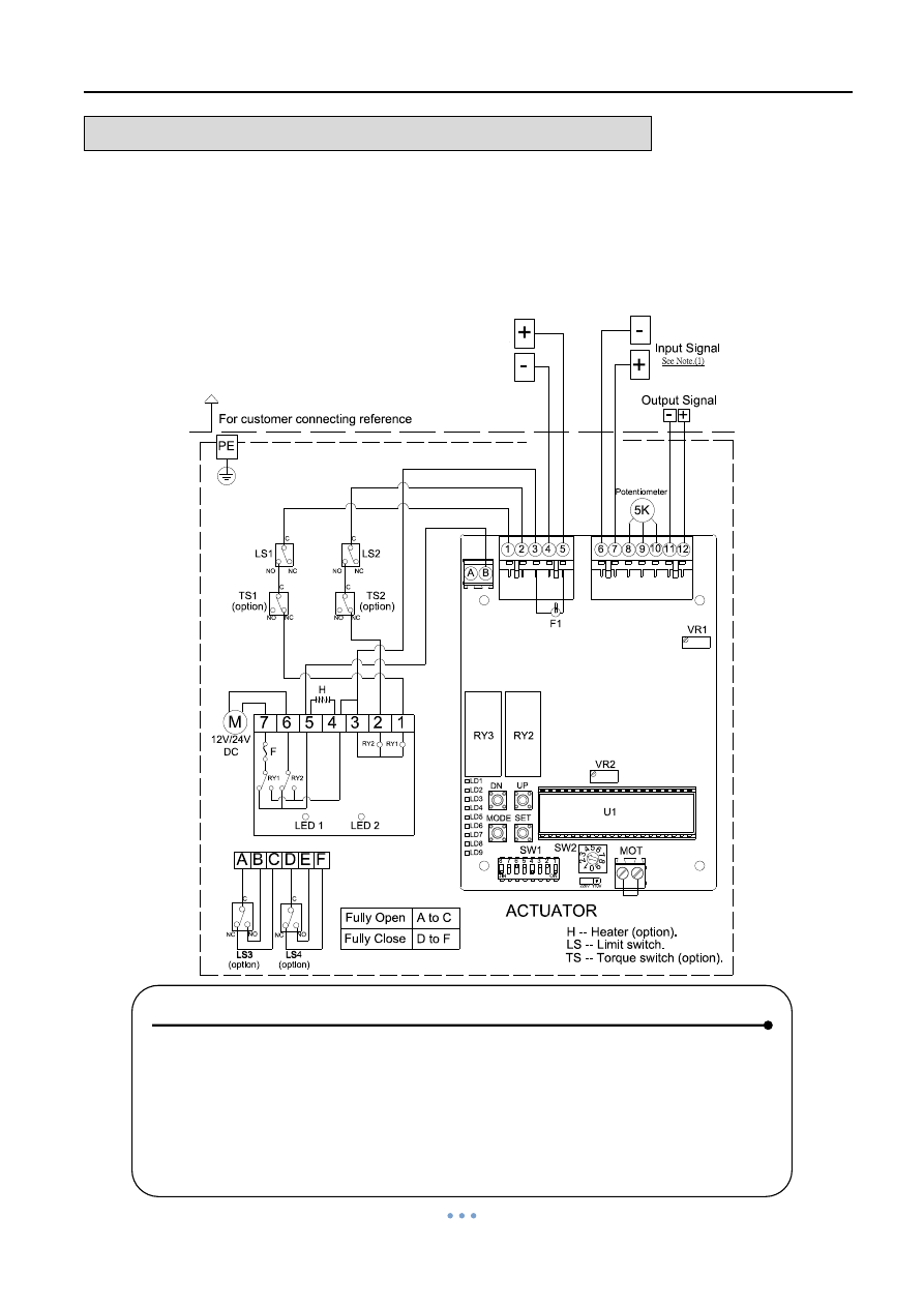
WIRING DIAGRAM
– Quarter Turn Actuator
OM-2 ~ OM-8 , OM-F , OM-G 110V , 220V AC 1-Phase
Modulating Controller
LS1
LS2
Input Signal
LS3
TS1
(opt
ion
)
(opt
ion
)
D
110V/220V
C
NO
C
NO
C
NC
C
NC
TS2
M
C
NO
C
NO
NC
NC
NC
NC
NO
NO
C
Power supply
110V/220V AC
For customer connecting reference
N
L
+
-
A
B
C
E
F
5K
Potentiometer
Output Signal
- +
Note:
(1). Modulating Board
(it is suggested to use the shielding wire and its length should not exceed 30m.)
Output Signal : 4-20mA, 2-10V
Input Signal : 4-20mA, 1-5V, 2-10V
Fully Open
Fully Close
A to C
D to F
AC
(option)
LS4
(option)
A B
1 2 3 4 5
6 7 8 9 10 11 12
F1
RY3
RY2
LD1
VR2
MOT
U1
VR1
SW1
SW2
220V 110V
DN
UP
MODE SET
1
0
9
8
7
6
5
4
3
2
ON
DIN
1
2
3
4
5
6
7
8
LD2
LD3
LD4
LD5
LD6
LD7
LD8
LD9
H
See Note.(1)
LS -- Limit switch.
TS -- Torque switch (option).
H -- Heater (option).
ACTUATOR
(2). Using less than 5A current for "A,B,C,D,E,F".
[ OM-2 ~ OM-8, OM-G, OM-F 110V, 220V AC 1-Phase ]
Modulating Controller, 30% duty cycle
PE
Power Supply
110V / 220V AC
NOTE:
1. Modulating Board
a. Input Signal:4~20mA, 1~5V, 2~10V
(It is suggested to use the shielding wire and its length should not
exceed 30m.)
b. Output Signal:4~20mA, 2~10V
2. Using less than 5
A current for “A, B, C, D, E, F”.
Quarter Turn Actuator 【OM series】
Sun Yeh Ele. Ind. Co., Ltd. | 2013.09
36
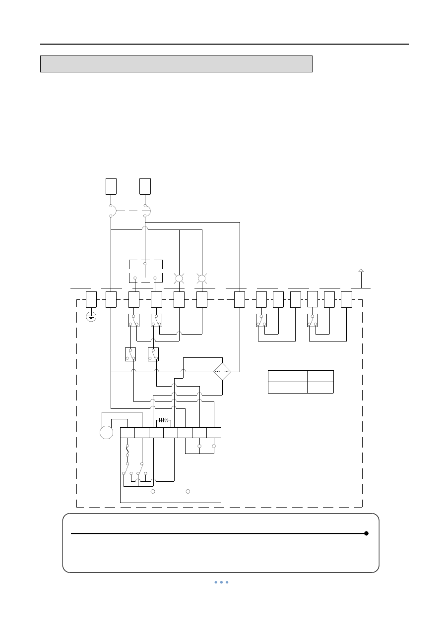
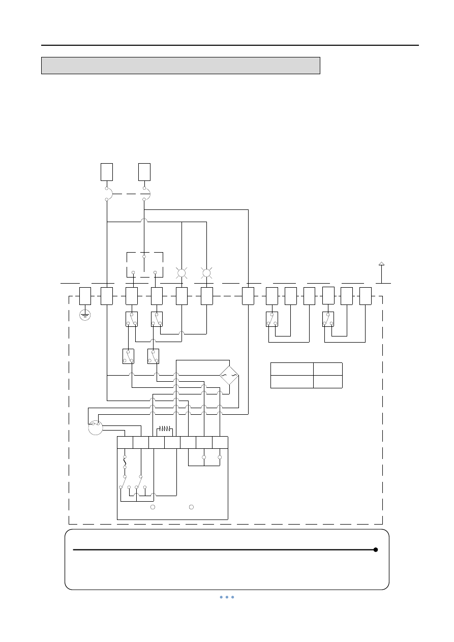
WIRING DIAGRAM
– Quarter Turn Actuator
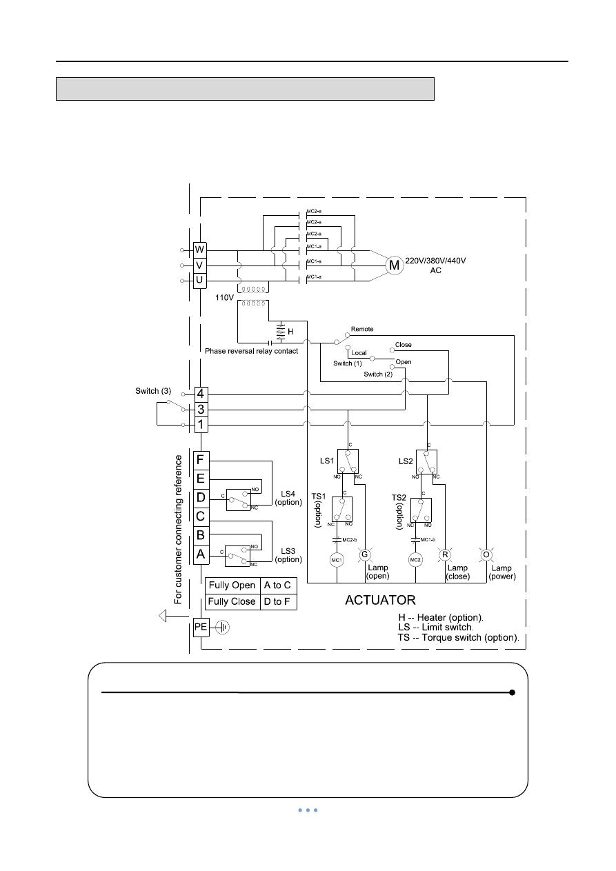
OM-2 ~ OM-13 220V , 380V , 440V AC 3-Phase
Modulating Controller
+
-
LS1
Input Signal
LS4
TS1
TS2
LS2
W
V
U
H
Switch (1)
Switch (2)
Remote
Local
Close
Open
M
G
R
O
Lamp
(open)
Lamp
(close)
Lamp
(power)
Power supply
220V/380V/440V
Note:
(1). Please change any two of U, V, W when the power lamp is off.
(3). Local / Remote Switches
Select "Local" : Controlled by switch (2)
3-PH
110V
(o
ptio
n
)
(o
ptio
n
)
(2). Modulating Board
[ OM-2 ~ OM-13 220V, 380V, 440V AC 3-Phase ]
MC2-a
MC1-a
MC2-a
MC2-a
MC1-a
MC1-a
MC2-b
MC1
MC2
Input Signal : 4-20mA, 2-10V, 1-5V
Output Signal : 4-20mA, 2-10V
(it is suggested to use the shielding wire and its length should not exceed 30m.)
A
Select "Remote" : Controlled by signal.
C
NO
NC
C
NO
NC
C
NC
C
NC
C
NC
NO
C
B
C
D
E
F
NC
NO
RY1
Phase reversal relay contact
MC1-b
NO
NO
RY1
RY1
Fo
r cu
stom
er c
on
ne
ctin
g re
fer
e
n
ce
5K
Potentiometer
Output Signal
- +
(option)
LS3
(option)
Fully Open
Fully Close
A to C
D to F
A B
1 2 3 4 5
6 7 8 9 10 11 12
F1
RY3
RY2
LD1
VR2
MOT
U1
VR1
SW1
SW2
220V 110V
DN
UP
MODE SET
1
0
9
8
7
6
5
4
3
2
ON
DIN
1
2
3
4
5
6
7
8
LD2
LD3
LD4
LD5
LD6
LD7
LD8
LD9
LS -- Limit switch.
TS -- Torque switch (option).
H -- Heater (option).
See Note.(1)
ACTUATOR
(4). Using less than 5A current for "A,B,C,E,F".
PE
220V/380V/440V
AC
Modulating Controller, 30%duty cycle
Power Supply
220V / 380V / 440V AC
3-PH
NOTE:
1. Please change any two of the U, V, W when the power lamp is off.
2. Modulating Board
a. Input Signal : 4~20mA, 2~10V, 1~5V
(It is suggested to use the shielding wire and its length should not
exceed 30m.)
b. Output Signal: 4~20mA, 2~10V
3. Local / Remote Switches
a.
Select “Remote”:Controlled by signal.
b. Select
“Local”:Controlled by switch (2).
4.
Using less than 5A current for “ A, B, C, D, E, F”.
See Note(2)
Quarter Turn Actuator 【OM series】
Sun Yeh Ele. Ind. Co., Ltd. | 2013.09
37
WIRING DIAGRAM
– Quarter Turn Actuator
OM-2 ~ OM-8 110V , 220V AC 1-Phase
Modulating Controller , 75% duty cycle
Power Supply
110V / 220V AC
NOTE:
1. Modulating Board
a. Input Signal:4~20mA, 1~5V, 2~10V
(It is suggested to use the shielding wire and its length should not
exceed 30m.)
b. Output Signal:4~20mA, 2~10V
2. Using less than 5
A current for “A, B, C, D, E, F”.
Quarter Turn Actuator 【OM series】
Sun Yeh Ele. Ind. Co., Ltd. | 2013.09
38
WIRING DIAGRAM
– Quarter Turn Actuator
OM-9 ~ OM-13 110V AC 1-Phase
Modulating Controller , 50% duty cycle
Power Supply
110V AC
NOTE:
1. Modulating Board
a. Input Signal:4~20mA, 1~5V, 2~10V
(It is suggested to use the shielding wire and its length should not
exceed 30m.)
b. Output Signal:4~20mA, 2~10V
2. Using less than 5
A current for “A, B, C, D, E, F”.
Quarter Turn Actuator 【OM series】
Sun Yeh Ele. Ind. Co., Ltd. | 2013.09
39
WIRING DIAGRAM
– Quarter Turn Actuator
OM-9 ~ OM-13 220V AC 1-Phase
Modulating Controller , 50% duty cycle
Power Supply
220V AC
NOTE:
1. Modulating Board
a. Input Signal:4~20mA, 1~5V, 2~10V
(It is suggested to use the shielding wire and its length should not
exceed 30m.)
b. Output Signal:4~20mA, 2~10V
2. Using less than 5
A current for “A, B, C, D, E, F”.
Quarter Turn Actuator 【OM series】
Sun Yeh Ele. Ind. Co., Ltd. | 2013.09
40
WIRING DIAGRAM
– Quarter Turn Actuator
OM-2 ~ OM-13 110V , 220V AC 1-Phase
On-Off Controller , Local Control Unit
N
L
ACTUATOR
110V/220V
AC
1
3
4
5
6
7
PE
110V/220V AC
R
M
C
S2
S1
Remote
Open
Close
(1). Using less than 5A current for "A,B,C,E,F".
H
Close
Open
LS1
LS2
TS1
[ OM-2~OM-13 110V, 220V AC 1-Phase ]
On-Off Controller, Local Control Unit, 30% duty cycle
CS
Lam
p
(op
en
)
Lamp
(cl
os
e)
(opti
on
)
(option)
B
LS3
A
(option)
F
E
D
C
Note:
Local
C
NC
NO
LS4
C
NC
NO
C
NC
NO
C
NC
NO
C
NC
TS2
(opti
on
)
C
NC
G
O
Lam
p
(po
we
r)
NO
NO
For customer connecting reference
Power supply
Fully Open
Fully Close
A to C
D to F
1-PH
LS -- Limit switch.
TS -- Torque switch (option).
H -- Heater (option).
Power Supply
110V / 220V AC
NOTE:
1.
Using less than 5A current for “A, B, C, D, E, F”.
Quarter Turn Actuator 【OM series】
Sun Yeh Ele. Ind. Co., Ltd. | 2013.09
41
WIRING DIAGRAM
– Quarter Turn Actuator
OM-2 ~ OM-13 220V , 380V , 440V AC 3-Phase
On-off Controller , Local Control Unit
Power Supply
220V / 380V / 440V AC
3-PH
NOTE :
1. Please change any two of the U, V, W when the power lamp is off.
2. Switch (3) is the switch of remote control (provided by user).
a. Connecting #1 & #3 for OPEN.
b. Connecting #1 & #4 for CLOSE.
c. #1, #3, #4 can not connect together at the same time.
3.
Using less than 5A current for “ A,B, C, D, E, F”.
Quarter Turn Actuator 【OM series】
Sun Yeh Ele. Ind. Co., Ltd. | 2013.09
42
WIRING DIAGRAM
– Quarter Turn Actuator
OM-2 ~ OM-8 110V , 220V AC 1-Phase
Modulating Controller , Local Control Unit
Power Supply
110V / 220V AC
NOTE :
1. Modulating Board
a. Input Signal:4~20mA, 1~5V, 2~10V
(It is suggested to use the shielding wire and its length should not
exceed 30m.)
b. Output Signal:4~20mA, 2~10V
2. Local / Remote Switches
a.
Select “Remote”:Controlled by signal.
b.
Select “Local”:Controlled by switch (2).
3.
Using less than 5A current for “A, B, C, D, E, F”.
See Note(1)
Quarter Turn Actuator 【OM series】
Sun Yeh Ele. Ind. Co., Ltd. | 2013.09
43
WIRING DIAGRAM
– Quarter Turn Actuator
OM-2 ~ OM-8 110V , 220V AC 1-Phase
Modulating Controller , Local Control Unit , 75% duty cycle
Power Supply
110V / 220V AC
NOTE :
1. Modulating Board
a. Input Signal:4~20mA, 1~5V, 2~10V
(It is suggested to use the shielding wire and its length should not
exceed 30m.)
b. Output Signal:4~20mA, 2~10V
2. Local / Remote Switches
a.
Select “Remote”:Controlled by signal.
b.
Select “Local “:Controlled by switch (2).
3.
Using less than 5A current for “A, B, C, D, E, F”.
See Note(1)
Quarter Turn Actuator 【OM series】
Sun Yeh Ele. Ind. Co., Ltd. | 2013.09
44
WIRING DIAGRAM
–
Quarter Turn Actuator
OM-9 ~ OM-13 110V AC 1-Phase
Modulating Controller , Local Control Unit , 50% duty cycle
Power Supply
110V AC
NOTE :
1. Modulating Board
a. Input Signal:4~20mA, 1~5V, 2~10V
(It is suggested to use the shielding wire and its length should not
exceed 30m.)
b. Output Signal:4~20mA, 2~10V
2. Local/Remote Switches
a.
Select “Remote”:Controlled by signal.
b.
Select “Local”:Controlled by switch (2).
3.
Using less than 5A current for “A, B, C, D, E, F”.
See Note(1)
Quarter Turn Actuator 【OM series】
Sun Yeh Ele. Ind. Co., Ltd. | 2013.09
45
WIRING DIAGRAM
– Quarter Turn Actuator
OM-9 ~ OM-13 220V AC 1-Phase
Modulating Controller , Local Control Unit , 50% duty cycle
Power Supply
220V AC
NOTE :
1. Modulating Board
a. Input Signal:4~20mA, 1~5V, 2~10V
(It is suggested to use the shielding wire and its length should not
exceed 30m.)
b. Output Signal:4~20mA, 2~10V
2. Local / Remote Switches
a.
Select “Remote”:Controlled by signal.
b. Sel
ect “Local”:Controlled by switch (2).
3.
Using less than 5A current for “A, B, C, D, E, F”.
See Note(1)
Quarter Turn Actuator 【OM series】
Sun Yeh Ele. Ind. Co., Ltd. | 2013.09
46
WIRING DIAGRAM
– Quarter Turn Actuator
OM-2 ~ OM-13 110V , 220V AC 1-Phase
On-off Controller , Local Control Unit , Analog Signal Output
Power Supply
110V / 220V AC
NOTE :
1.
Using less than 5A current for “A, B, C, D, E, F”.
2. If the control power is 220V AC, N & L connect to #1 & #3.
If the control power is 110V AC, N & L connect to #1 & #2 or #2 & #3.
Quarter Turn Actuator 【OM series】
Sun Yeh Ele. Ind. Co., Ltd. | 2013.09
47
WIRING DIAGRAM
– Quarter Turn Actuator
OM-2 ~ OM-13
220V , 380V , 440V AC 3-Phase
On-off Controller , Local Control Unit , Analog Signal Output
Power Supply
220V / 380V / 440V AC
3-PH
NOTE :
1. Please change any two of the U, V, W when the power lamp is off.
2. Switch (3) is the switch of remote control (provided by user).
a. Connecting #1 & #3 for OPEN.
b. Connecting #1 & #4 for CLOSE.
c. #1, #3, #4 can not connect together at the same time.
3.
Using less than 5A current for “ A,B, C, D, E, F”.
Quarter Turn Actuator 【OM series】
Sun Yeh Ele. Ind. Co., Ltd. | 2013.09
48
WIRING DIAGRAM
– Quarter Turn Actuator
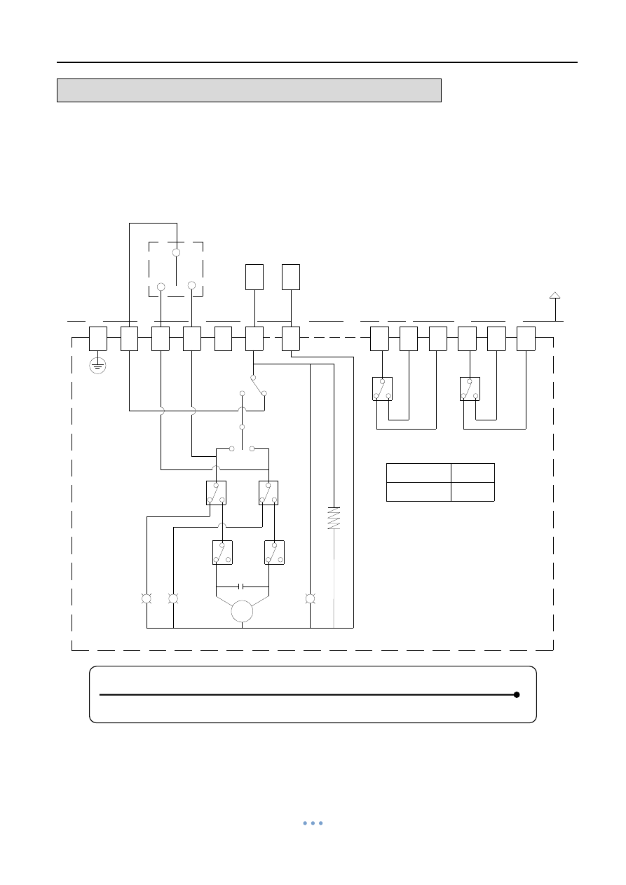
BM-2, OM-A, OM-A-M, OM-1~OM-13, OM-F, OM-G
110V, 220V AC 1-Phase
Same Switch Coupling Wiring
Power Supply
110V / 220V AC
NOTE :
1. The wiring is based on 3 sets of actuators for one switch
– 1 set is open
and 2 sets are close. (If more sets, the rest can be done by this logic.)
2. When a set of control wire or switch needs to control two or more
actuators at the same time, please refer to the wiring diagram.
3. Add one contactor for separation to prevent the interference of
compression coupling.
4. C1=3a3b contactor

Quarter Turn Actuator 【OM series】
Sun Yeh Ele. Ind. Co., Ltd. | 2013.09
49
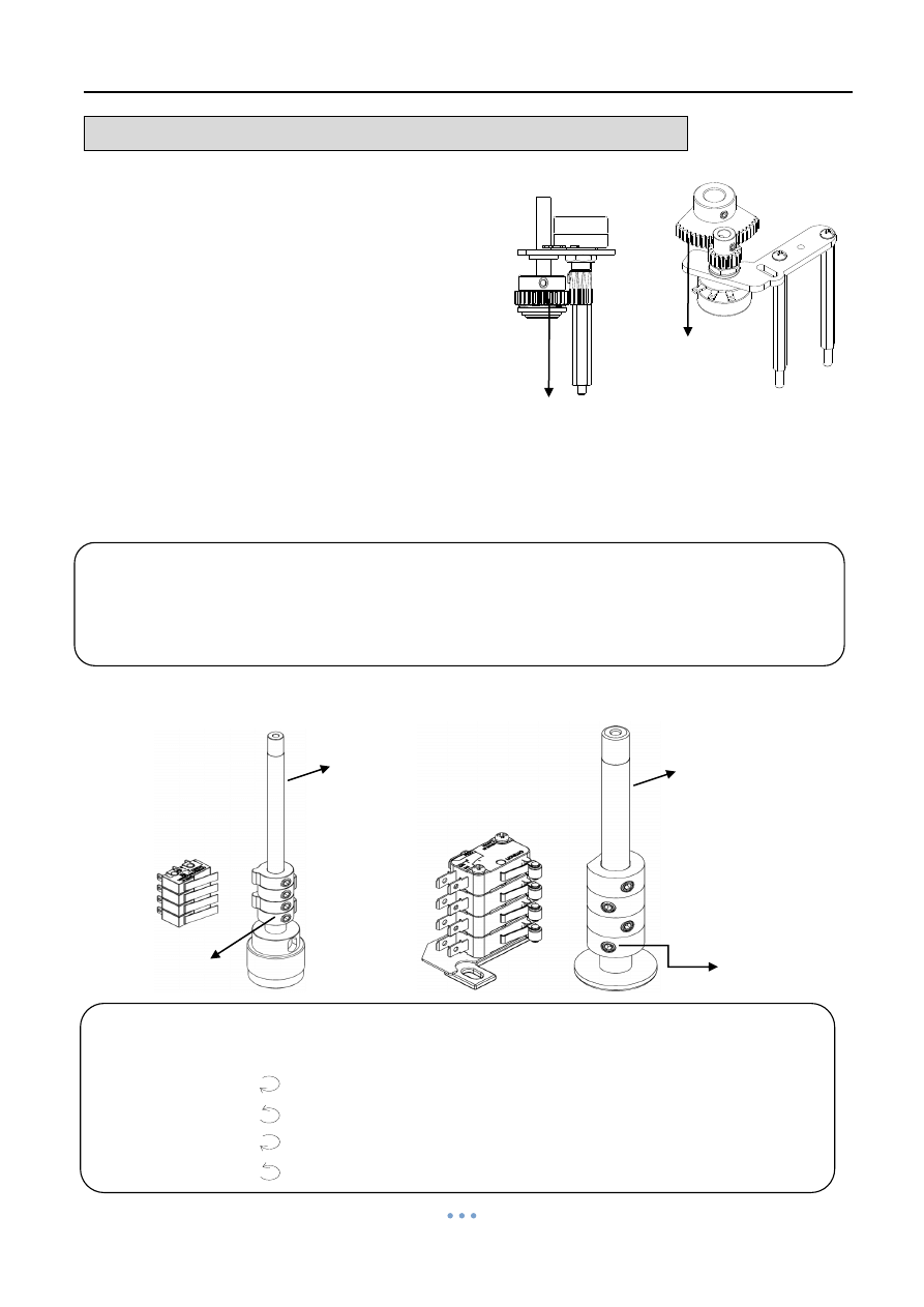
ADJUSTMENT
– Travel Cam & Limit Switches
The travel cams are set to control the open and closed position of the valve. The
position is set to stop the travel of the actuator when the travel cams activate the limit switch.
Standard is two limit switches (LS1 & LS2), one for open, one for closed. LS1 & LS2 limit
the maximum range by disabling the electric motor. LS3 & LS4 are optional. They allow
external equipment to confirm that the valve has reached the fully open and fully closed
positions.
The travel cams can be adjusted with a 2.5mm Allen key. The cams are preset at the
factory. When additional adjustments are needed, follow steps described below.
OM-A, OM-A-M
1. To set the open position:
a. Turn power off.
b. Use manual override to turn valve to the fully-open position.
c. Remove cover and loosen the M5 set screw on the TC1 with a 2.5mm Allen Key.
d. Rotate cam(TC1) counterclockwise to contact with switch.
e. Slowly rotate cam(TC1) clockwise until a light click is heard.
f. Securely tighten the M5 set screw and apply power to check the travel position. If
the position is not correct, please repeat steps a ~ f.
g. After the adjustment is completed, check again the M5 set screw is securely
tightened.
2. To set the close position:
a. Turn power off.
b. Use manual override to turn valve to the fully-closed position.
c. Loosen the M5 set screw on the TC2 with a 2.5mm Allen key.
d. Rotate cam(TC2) clockwise to contact with switch.
e. Slowly rotate cam(TC2) counterclockwise until a light click is heard.
f. Securely tighten the set screw and apply power to check the traveling position. If the
position is not correct, please repeat steps a ~ f.
g. After the adjustment is completed, check again the M5 set screw is securely
tightened.
NOTE:
If LS3 & LS4 are fitted, they should be set to trip prior to LS1 & LS2 to avoid
over-travel.
further travel.
Modulating type: Loosen M5 set screw on round gear before setting, after
completing fully-open and fully-closed calibration, run the actuator to fully-closed
position, then rotate round gear counterclockwise to the end and tighten M5 set
screw.
Quarter Turn Actuator 【OM series】
Sun Yeh Ele. Ind. Co., Ltd. | 2013.09
50
ADJUSTMENT
– Travel Cam & Limit Switches
【OM-A, OM-A-M】
OM-1, BM-2, OM2~13, OM-F, OM-G
1. To set the open position:
a. Turn power off and loosen both mechanical stops (Please refer
to
P52
and except
OM-A, BM-2, OM-A, OM-A-M).
b. Use manual override to turn valve to the fully-open position.
c. Remove cover and loosen the M5 set screw on the TC1 with a 2.5mm Allen key.
d. Rotate cam(TC1) clockwise to contact with switch.
e. Slowly rotate cam(TC1) counterclockwise until a light click is heard.
f. Securely tighten the set screw and apply power to check the travel position. If the
position is not correct, please repeat steps a ~ f.
g. After the adjustment is completed, check again the M5 set screw is securely
tightened.
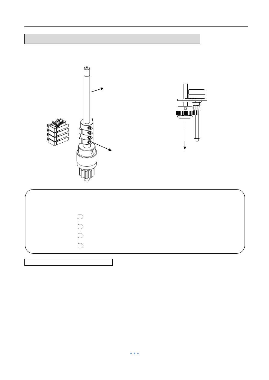
LS4
LS3
LS2
LS1
TC4
TC3
TC2
TC1
Set Screw M5
Round gear
Shaft
TC 4 Synchronous turn with TC2 (optional).
TC 3 Synchronous turn with TC1 (optional).
TC 2
“CLOSE”
TC
1 “ OPEN” Clockwise: decrease opening degree.
Counterclockwise: increase opening degree to fully open.
"OPEN"
"CLOSE"
Clockwise :Decrease closed degree.
degree to fully close.
Counter-clockwise:Increase closed
Clockwise:Increase opening degree
to fully open.
Counter-clockwise:Deccrease opening
degree .
"LS4" Synchronous turn with LS2(Option)
"LS3" Synchronous turn with LS1(Option)
LS1
LS1
LS2
LS3
LS4
LS2
LS3
LS4
(OM-1)
Adjust Travel Cam
Clockwise: increase closing degree to fully closed.
Counterclockwise: decrease closing degree.
"OPEN"
"CLOSE"
Clockwise :Decrease closed degree.
degree to fully close.
Counter-clockwise:Increase closed
Clockwise:Increase opening degree
to fully open.
Counter-clockwise:Deccrease opening
degree .
"LS4" Synchronous turn with LS2(Option)
"LS3" Synchronous turn with LS1(Option)
LS1
LS1
LS2
LS3
LS4
LS2
LS3
LS4
(OM-1)
Adjust Travel Cam
Quarter Turn Actuator 【OM series】
Sun Yeh Ele. Ind. Co., Ltd. | 2013.09
51
ADJUSTMENT
– Travel Cam & Limit Switches
2. To set the close position:
a. Turn power off.
b. Use manual override to turn valve to the
fully closed position.
c. Loosen the M5 set screw on the TC2 with
a 2.5mm Allen key.
d. Rotate cam(TC2) counterclockwise to
contact with switch.
e. Slowly rotate cam(TC2) clockwise until a
light click is heard.
f. Securely tighten the set screw and apply
power to check the travel position. If the
position is not correct, please repeat steps a ~ f.
g. After the adjustment is completed, check again the M5 set screw is securely
tightened.
h. Tighten both mechanical stops and per P52.
【OM-1】 【BM-2, OM-2~13, OM-F, OM-G】
LS4
LS3
LS2
LS1
Shaft
LS4
LS3
LS2
LS1
TC4
TC3
TC2
TC1
TC4
TC3
TC2
TC1
Shaft
LS4
LS3
LS2
LS1
Round gear
Sector gear
Modulating type: Loosen M5 set screw on sector gear (Round gear) before
setting, after completing fully-open and fully-closed calibration, run the actuator to
fully-closed position, then rotate sector gear (Round gear) clockwise to the end and
tighten M5 set screw.
Set Screw M5
Set Screw M5
TC 4 Synchronous turn with TC2 (optional).
TC 3 Synchronous turn with TC1 (optional).
TC 2
“CLOSE”
TC
1 “ OPEN” Clockwise: increase opening degree to fully-open.
Counterclockwise: decrease opening degree.
Clockwise: decrease closing degree.
Counterclockwise: increase closing degree to fully-closed.
"OPEN"
"CLOSE"
Clockwise :Decrease closed degree.
degree to fully close.
Counter-clockwise:Increase closed
Clockwise:Increase opening degree
to fully open.
Counter-clockwise:Deccrease opening
degree .
"LS4" Synchronous turn with LS2(Option)
"LS3" Synchronous turn with LS1(Option)
LS1
LS1
LS2
LS3
LS4
LS2
LS3
LS4
(OM-1)
Adjust Travel Cam
Quarter Turn Actuator 【OM series】
Sun Yeh Ele. Ind. Co., Ltd. | 2013.09
52
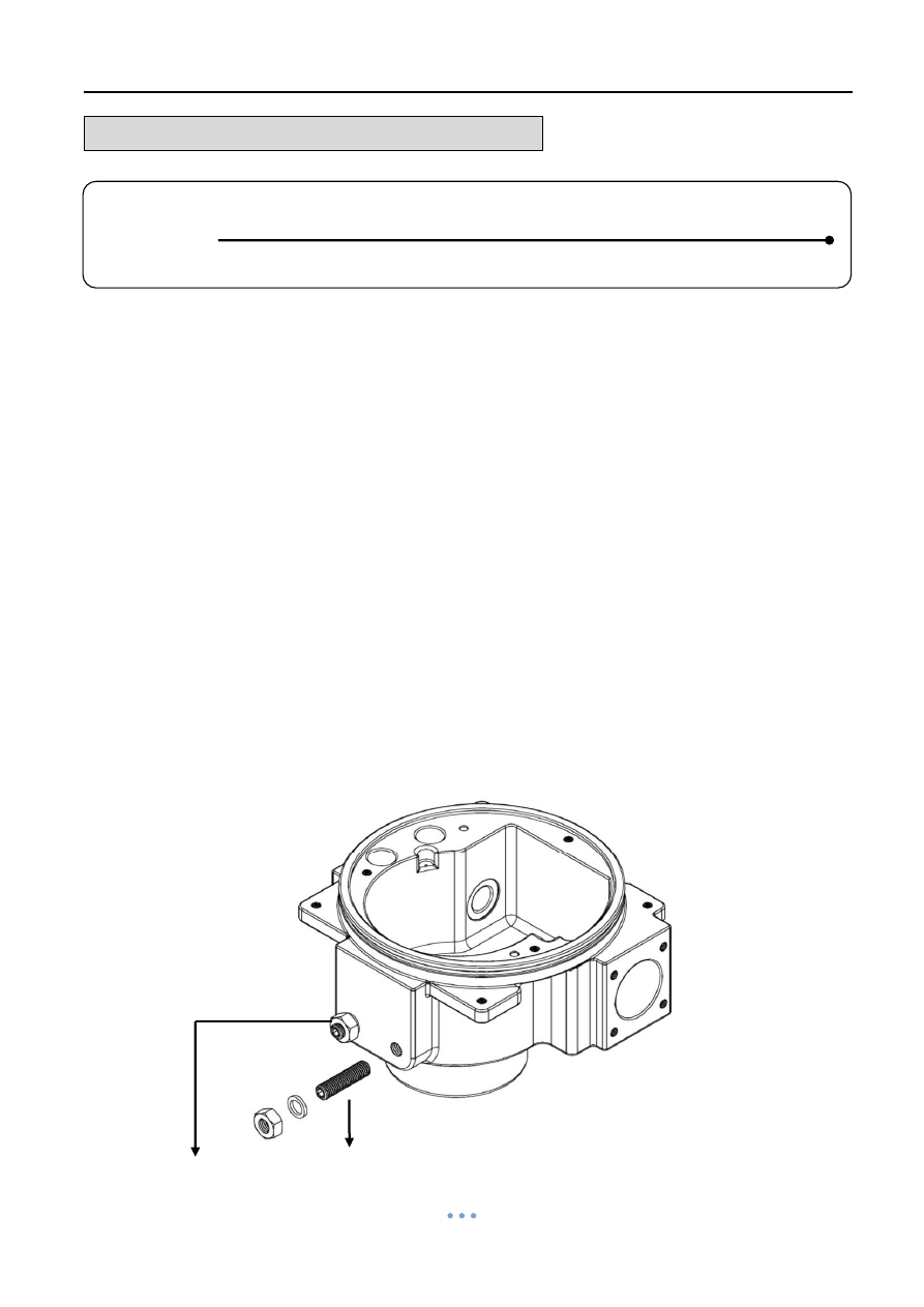
ADJUSTMENT
– Mechanical Stops
The Mechanical stops are factory set, though in some cases adjustment may be required
once a valve is fitted.
1. For Electric Operation
Please refer to “Adjustment – Travel Cam & Limit Switches”.
2. For Manual Operation
a. Turn power off.
b. Loosen locknut and unwind it a few turns.
c. For modulating type, loosen the set screw on the sector gear first.
d. Use manual override to turn the actuator to desire limit position.
e. For modulating type, rotate sector gear clockwise to the end. Then tighten set screw.
f. Tighten the mechanical stop screw until it reaches the shaft, then reverse one cycle.
g. Tighten locknut.
h. Check that the electrical limit switches can still be reached.
【OPEN】
【CLOSE】
CAUTION!
Mechanical stops should only be reached during manual operation.
!
Quarter Turn Actuator 【OM series】
Sun Yeh Ele. Ind. Co., Ltd. | 2013.09
53
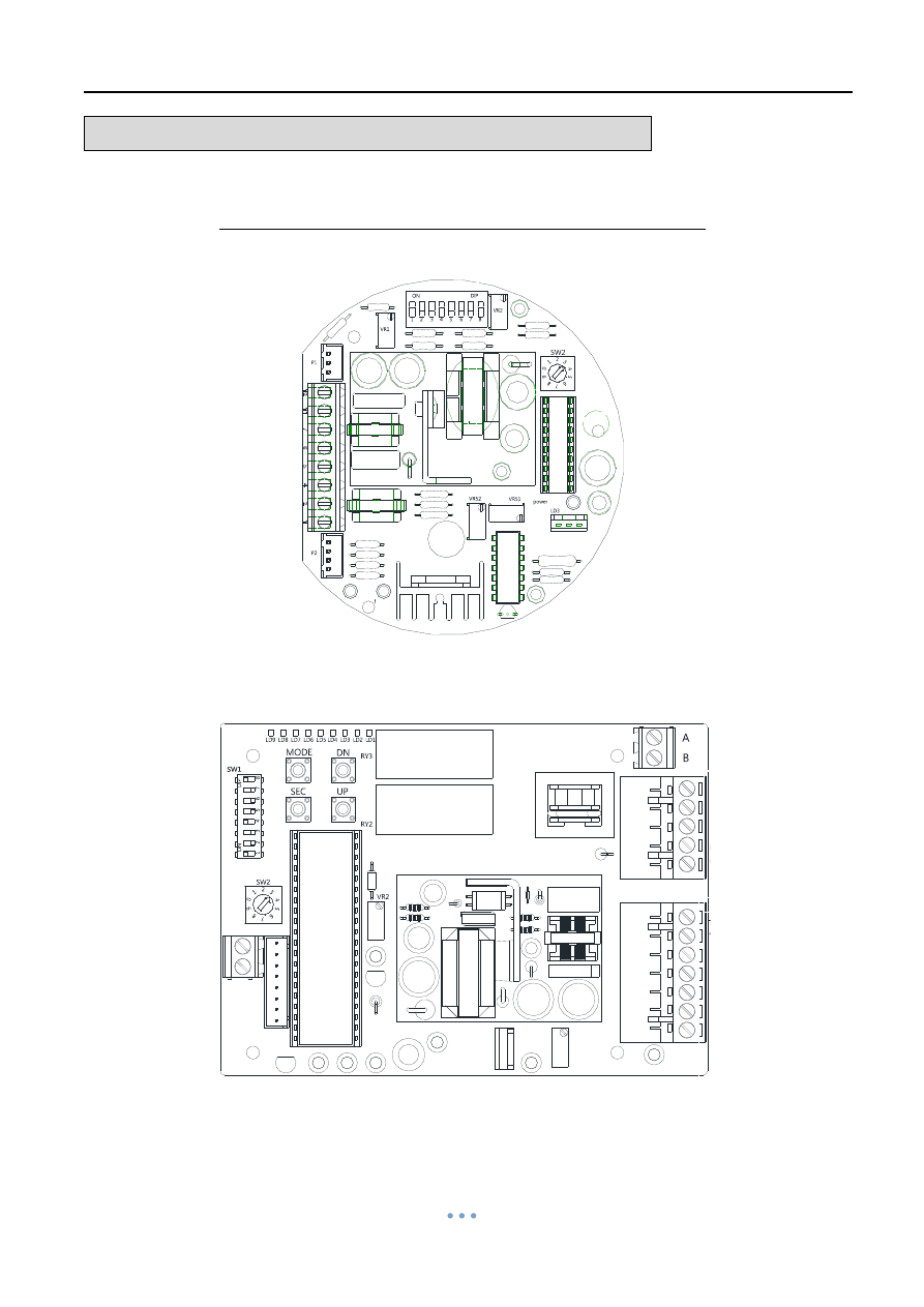
ADJUSTMENT
– Modulating Control Board
Part A: Suitable for OM-1~OM-13、OM-A、OM-A-M、OM-F、OM-G
1. Surface
The surface is based on the actuator in 110 / 220V voltage.
OM-1、OM-A、OM-A-M
OM-2~OM-13、OM-F、OM-G
12
11
7
6
5
4
2
1
6
7
8
9
10
11
12
1
2
3
4
5
Quarter Turn Actuator 【OM series】
Sun Yeh Ele. Ind. Co., Ltd. | 2013.09
54
ADJUSTMENT
– Modulating Control Board
Part A: Suitable for OM-1~OM-13、OM-A、OM-A-M、OM-F、OM-G
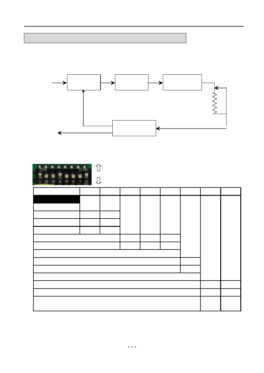
2. Procedure
Supplied Voltage :
24V DC / AC, 110V / 220V AC 1- Phase
3. DIP-SWITCH SETTING (SW1)
1
2
3
4
5
6
7
8
Factory setting
ON
OFF
OFF
ON
OFF
OFF
OFF
ON
4~20mA input
ON
OFF
1~5V input
OFF
OFF
2~10V input
OFF
ON
4~20mA output
OFF
ON
OFF
2~10V output
ON
OFF
ON
20mA / 5V / 10V means valve fully-open
OFF
20mA / 5V / 10V means valve fully-closed
ON
Close valve if input signal disconnected ( when S6 sets “ OFF”)
OFF
ON
Open valve if input signal disconnected ( when S6 sets “ OFF”)
ON
OFF
Actuator will not operate if input signal disconnected
(when S6 sets “ OFF”)
ON
OFF
ON
OFF
NOTE:
1. After completing dip-switch setting, restart the actuator.
2. The standard factory presetting is 1, 4, 8 for ON and 2, 3, 5, 6, 7 for OFF.
Output Signal:
4 ~ 20mA
2 ~ 10V DC
Input Signal:
4 ~ 20mA
2 ~ 10V DC
1 ~ 5 V DC
Control Part
Driving Part
Comparison
Part
Control Object
Driving Part
Control Volume
Valve 90°
Feedback Signal
270°VR
(5K Ohm)
OFF
ON
Quarter Turn Actuator 【OM series】
Sun Yeh Ele. Ind. Co., Ltd. | 2013.09
55
ADJUSTMENT
– Modulating Control Board
Part A: Suitable for OM-1~OM-13、OM-A、OM-A-M、OM-F、OM-G
FUNCTION
SETTING
S1, 2
INPUT SIGNAL SELECT.
“4~20mA” set 1-ON / 2-OFF.
“1~5V” set 1-OFF / 2-OFF.
“2~10V” set 1-OFF / 2-ON.
S3, 4, 5
OUTPUT SIGNAL SELECT.
“4~20mA” set 3-OFF / 4-ON / 5-OFF.
“2-10V” set 3-ON / 4-OFF / 5-ON.
When S6 sets “ON ”
S6
INPUT SIGNAL SELECT:
4mA, 2V, 1V valve fully-open.
20mA, 10V, 5V valve fully-closed.
Set 6-ON.
S7, 8
POSITION SELECT.
(When the input signal fails.)
“valve fully-closed” set 7-ON / 8-OFF.
“valve fully-open” set 7-OFF / 8-ON.
“valve stops” set 7-ON / 8-ON.
or 7-OFF/ 8-OFF.
When S6 sets “OFF ”
S6
INPUT SIGNAL SELECT:
4mA, 2V, 1V valve fully-closed.
20mA, 10V, 5Vvalve fully-open.
Set 6-OFF.
S7, 8
POSITION SELECT.
(When the input signal fails.)
“valve fully-closed” set 7-OFF / 8-ON.
“valve fully-open” set 7-ON / 8-OFF.
“valve stops” set 7-ON / 8-ON.
or 7-OFF / 8-OFF.

Quarter Turn Actuator 【OM series】
Sun Yeh Ele. Ind. Co., Ltd. | 2013.09
56
ADJUSTMENT
– Modulating Control Board
Part A: Suitable for OM-1~OM-13、OM-A、OM-A-M、OM-F、OM-G
4. Sensitivity Switch Setting(SW2)
a.
When switch to “1”: The Highest Sensitive and the 0~90 degree can be divided up to
around 50 times movement.
b.
When switch to “0”: The Lowest Sensitive and the 0~90 degree can be divided up to
around 10 times movement.
c. The sensitivity decreases 5 times movement by sectors from SW1 to SW2, SW2 to
SW3, SW3 to SW4 and so on.
5. Settings for OPEN and CLOSE (OM-1, OM-A, OM-A-M)
The settings are set at factory, though in some cases re-set may be required when a
particular rate of signal is requested.
Adjust output signal/input signal
VR1
— Adjust 10V, 20mA (Input signal: fully-open)
VR51
— Adjust 10V, 20mA (Output signal: fully-open)
VR2
— Adjust 2V, 4mA (Input signal: fully-closed)
VR52
— Adjust 2V, 4mA (Output signal: fully-closed)
Note: If it is necessary to adjust VR51 and VR52, VR1 and VR2 also need to be adjusted
accordingly.
a.
Rotate VR1 counterclockwise until a light click is heard, then supply 10V (or 20mA) to
modulating board. Slightly rotate VR1 clockwise until green LED keeps on. Adjust
VR51 to complete.
Clockwise: decreasing signal.
VR51:
Counterclockwise: increasing signal.
b. Rotate VR2 clockwise until a light click is heard, then supply 2V (or 4mA) to
modulating board. Slightly rotate VR2 counterclockwise until red LED keeps on.
Adjust VR51 to complete.
Clockwise: decreasing signal.
VR52:
Counterclockwise: increasing signal.
The function of VR
"OPEN"
"CLOSE"
Clockwise :Decrease closed degree.
degree to fully close.
Counter-clockwise:Increase closed
Clockwise:Increase opening degree
to fully open.
Counter-clockwise:Deccrease opening
degree .
"LS4" Synchronous turn with LS2(Option)
"LS3" Synchronous turn with LS1(Option)
LS1
LS1
LS2
LS3
LS4
LS2
LS3
LS4
(OM-1)
Adjust Travel Cam

Quarter Turn Actuator 【OM series】
Sun Yeh Ele. Ind. Co., Ltd. | 2013.09
57
ADJUSTMENT
– Modulating Control Board
Part A: Suitable for OM-1~OM-13、OM-A、OM-A-M、OM-F、OM-G
6. Settings for OPEN and CLOSE (OM-2~OM-13、OM-F、OM-G)
The settings are set at factory, though in some cases re-set may be required when a
particular rate of signal is requested.
OPEN setting
a.
Keep pressing “SET” for 2 seconds, then LD 9 comes on, it will enter to the manual
mode.
b.
Keep pressing “UP” until actuator runs to fully-open position, LD2 comes on, then
supplies the input signal (5V or 10V or 20mA).
c.
Press “MODE” once. The OPEN setting is completed.
CLOSE setting
a.
Keep pressing “DOWN”, until actuator runs to fully-closed position, LD1 comes on ,
then supplies input signal (1V or 2V or 4mA).
b.
Press “MODE” once. The CLOSE setting is completed.
After completing the above settings, press “SET” once
Adjust output signal
Clockwise: increasing signal.
VR2:
Counterclockwise: decreasing signal.
"OPEN"
"CLOSE"
Clockwise :Decrease closed degree.
degree to fully close.
Counter-clockwise:Increase closed
Clockwise:Increase opening degree
to fully open.
Counter-clockwise:Deccrease opening
degree .
"LS4" Synchronous turn with LS2(Option)
"LS3" Synchronous turn with LS1(Option)
LS1
LS1
LS2
LS3
LS4
LS2
LS3
LS4
(OM-1)
Adjust Travel Cam
Quarter Turn Actuator 【OM series】
Sun Yeh Ele. Ind. Co., Ltd. | 2013.09
58
ADJUSTMENT
– Modulating Control Board
Part A: Suitable for OM-1~OM-13、OM-A、OM-A-M、OM-F、OM-G
7. Lamp Signal (OM-2~OM-13、OM-F、OM-G)
If the LED (LD4~LD9) is flashing under modulating control, refer to the following
"Modulating Board Troubleshooting".
Lamp
Possibilities
Solution
No Lamp
(LD3 off)
a. No power supply.
b. The voltage is over 260V to
cause the board burn out.
c. Wrong connecting for the #8, #9
of the VR.
d. Faulty Modulating board.
a. Check the power supply and
wiring (#4 & #5 of modulating
board).
b. Check the voltage.
c. Check the wiring.
d. Send back to factory for
inspection.
LD5
a. Setting in 2-10V input signal but
supply 4-20mA.
b. Setting in 2-10V input signal, but
the input signal is over 13.5V.
**Setting in 4-20mA but supply 2-10V
signal. The actuator could still be
operated within 2~7V. But if the
signal is over 7.2V the LED5 will
come ON.
Confirm if the input signal is the
same as dip switch setting
( refer to P54~P55).
LD 6
Motor thermostat turns off.
a. Too high frequency for rated duty
cycle(refer to P2).
b. Motor thermostat (MOT) is not
connected.
LD7
a. Output signal short circuit.
b. Wrong connecting of the 2-10V
input signal.
a. Confirm the wiring of output
signal #11(-)、#12(+).
b. Confirm the input signal for
#6(-)、#7(+).
LD8
Motor current is excessive.
a. Too high frequency for rated duty
cycle (refer to P2).
b. Check the load (refer to P4~P5).
c. Check if the motor rotor is locked
(For example: Valve is stuck by
foreign objects).
LD9
Manual Mode - Setting position for
open & close.
After completing the settings, press
“SET” once.
LD1
Fully-closed
LD6
Motor thermostat turn off
LD2
Fully-open
LD7
Output signal short circuit
LD3
Power
LD8
Motor current is excessive
LD4
Abnormal Voltage
LD9
Manual Mode
LD5
Wrong input signal
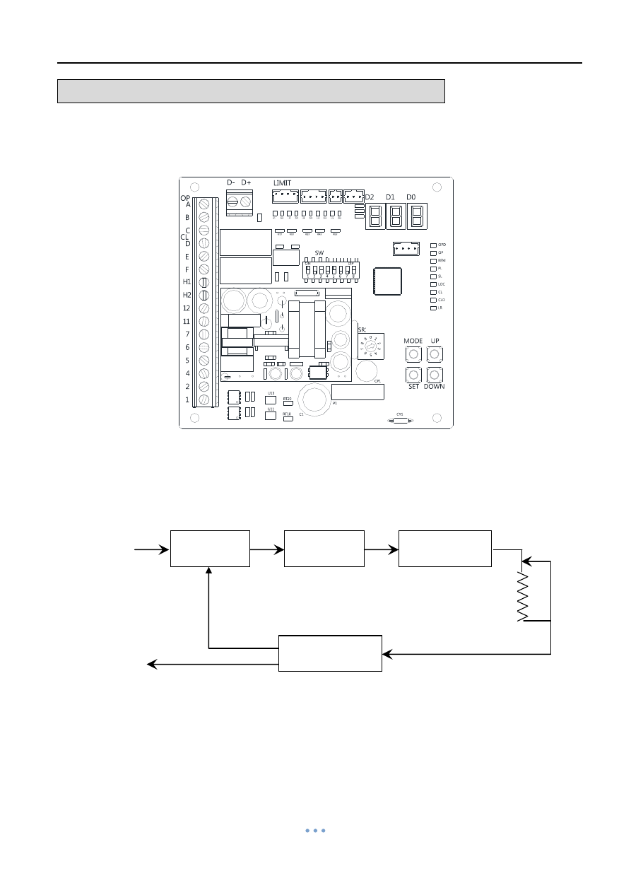
Quarter Turn Actuator 【OM series】
Sun Yeh Ele. Ind. Co., Ltd. | 2013.09
59
ADJUSTMENT
– Modulating Control Board
Part B: Suitable for OM-1、OM-A、OM-A-M (Option: MODBUS)
1. Surface
2. Procedure
Output Signal:
4 ~ 20mA
2 ~ 10V DC
Input Signal:
4 ~ 20mA
2 ~ 10V DC
1 ~ 5 V DC
Control Part
Driving Part
Comparison
Part
Control Object
Driving Part
Control Volume
Valve 90°
Feedback Signal
270°VR
(5K Ohm)
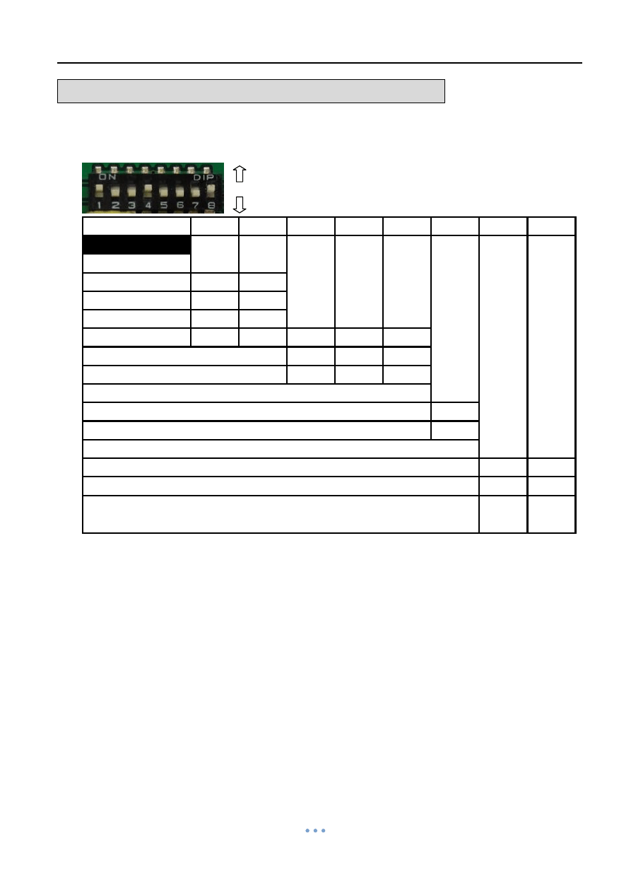
Quarter Turn Actuator 【OM series】
Sun Yeh Ele. Ind. Co., Ltd. | 2013.09
60
ADJUSTMENT
– Modulating Control Board
Part B: Suitable for OM-1、OM-A、OM-A-M (Option: MODBUS)
3. DIP-SWITCH SETTING (SW)
1
2
3
4
5
6
7
8
Factory setting
ON
OFF
OFF
ON
OFF
OFF
OFF
ON
4~20ma input
ON
OFF
1~5V input
OFF
OFF
2~10V input
OFF
ON
MODBUS
ON
ON
ON
ON
ON
4-20mA output
OFF
ON
OFF
2-10V output
ON
OFF
ON
20mA / 5V / 10V means valve fully-open
OFF
20mA / 5V / 10V means valve fully-closed
ON
Close valve if input signal disconnected (
when S6 sets “ OFF”)
OFF
ON
Open valve if input signal disconnected ( when S6 sets “ OFF”)
ON
OFF
Actuator will not operate if input signal disconnected
(when S6 sets “ OFF”)
ON
OFF
ON
OFF
NOTE:
1. After completing dip-switch setting, restart the actuator or wait for 5 secs.
2. The standard factory presetting is 1, 4, 8 for ON and 2, 3, 5, 6, 7 for OFF.
。
OFF
ON

Quarter Turn Actuator 【OM series】
Sun Yeh Ele. Ind. Co., Ltd. | 2013.09
61
ADJUSTMENT
– Modulating Control Board
Part B: Suitable for OM-1、OM-A、OM-A-M (Option: MODBUS)
FUNCTION
SETTING
S1, 2
INPUT SIGNAL SELECT.
“4~20mA” set 1-ON / 2-OFF.
“1~5V” set 1-OFF / 2-OFF.
“2~10V” set 1-OFF / 2-ON.
S3, 4, 5
OUTPUT SIGNAL SELECT.
“4~20mA” set 3-OFF / 4-ON / 5-OFF.
“2-10V” set 3-ON / 4-OFF / 5-ON.
“MODBUS” set 3-ON / 4-ON / 5-ON.
When S6 sets “ON ”
S6
INPUT SIGNAL SELECT:
4mA, 2V, 1V valve fully-open.
20mA, 10V, 5V valve fully-closed.
Set 6-ON.
S7, 8
POSITION SELECT.
(When the input signal fails.)
“valve fully-closed” set 7-OFF / 8-ON.
“valve fully-open” set 7-ON / 8-OFF.
“valve stops” set 7-ON / 8-ON.
or 7-OFF/ 8-OFF.
When S6 sets “OFF ”
S6
INPUT SIGNAL SELECT:
4mA, 2V, 1V valve fully-closed.
20mA, 10V, 5Vvalve fully-open.
Set 6-OFF.
S7, 8
POSITION SELECT.
(When the input signal fails.)
“valve fully-closed” set 7-OFF / 8-ON.
“valve fully-open” set 7-ON / 8-OFF.
“valve stops” set 7-ON / 8-ON.
or 7-OFF / 8-OFF.
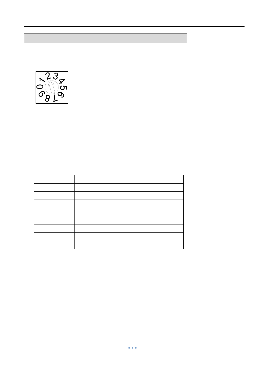
Quarter Turn Actuator 【OM series】
Sun Yeh Ele. Ind. Co., Ltd. | 2013.09
62
ADJUSTMENT
– Modulating Control Board
Part B: Suitable for OM-1、OM-A、OM-A-M (Option: MODBUS)
4. Sensitivity Switch Setting (SR1)
a.
When switch to “1”: The highest sensitive and can be divided up to around 76 times
movement. The accumulative variation for each movement is 0.2mA.
b. When switch to "0": The lowest sensitive and can be divided up to around 15 times
movement. The accumulative variation for each movement is 1.0mA.
5. Lamp Indication
Lamp
Actuator Status
OPD
Fully-open position
OP
Opening direction
REM
Remote control mode
PL
Alerting signal
SL
Setting mode
LOC
Local control mode
CL
Closing direction
CLD
Fully-closed position
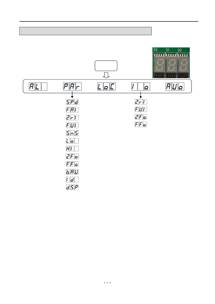
Quarter Turn Actuator 【OM series】
Sun Yeh Ele. Ind. Co., Ltd. | 2013.09
63
ADJUSTMENT
– Modulating Control Board
Part B: Suitable for OM-1、OM-A、OM-A-M (Option: MODBUS)
6. LED Indication
a. Setup flow chart
MODE
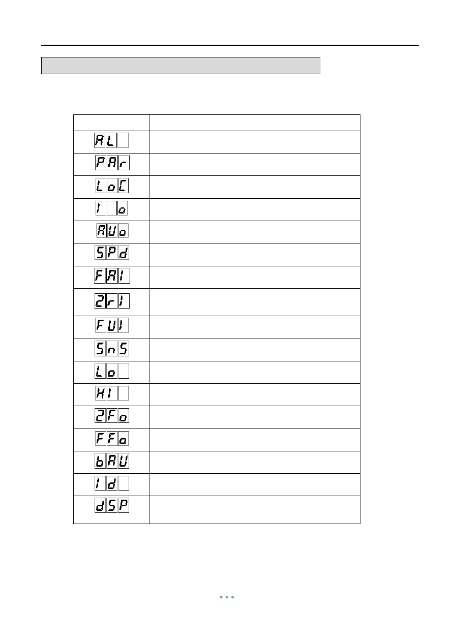
Quarter Turn Actuator 【OM series】
Sun Yeh Ele. Ind. Co., Ltd. | 2013.09
64
ADJUSTMENT
– Modulating Control Board
Part B: Suitable for OM-1、OM-A、OM-A-M (Option: MODBUS)
b. The funtion of LED indication
LED indication
Function
Error log
Basic parameter
Local control
Fast setting
Auto run
Running time setting
Wrong input signal
Input signal setting for fully-closed position
Input signal setting for fully-open position
Sensitivity Setting
Fully-closed position setting
Fully-open position setting
Output signal setting for fully-closed position
Output signal setting for fully-open position
Baud rate setting for MODBUS
Station setting for MODBUS
Display setting
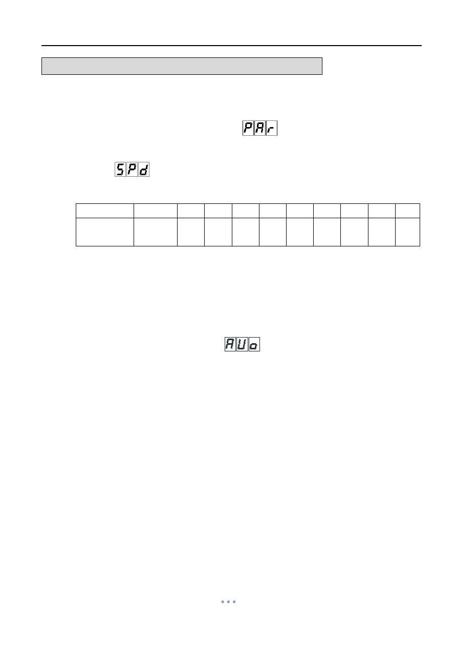
Quarter Turn Actuator 【OM series】
Sun Yeh Ele. Ind. Co., Ltd. | 2013.09
65
ADJUSTMENT
– Modulating Control Board
Part B: Suitable for OM-1、OM-A、OM-A-M (Option: MODBUS)
7. Adjustable Speed Setting
a.
Press “MODE” several times to get into
, then press “SET” once to enter
parameter setting mode.
b. Get into
and keep
pressing “SET” (around 3 sec) to enter setting mode.
c.
Adjust with “UP” and “DOWN” to the required selection.
Selection
1
2
3
4
5
6
7
8
9
10
Running time
(Sec.)
Standard
30
60
80
100
120
150
180
200
200
d.
Press “SET” once to complete the adjustable speed setting.
e.
Press “MODE” five times to go back to position indicator to complete the setting.
8. Travel Setting
a.
Press “MODE” five times to get into
.
b.
Keep pressing “SET” (around 5 sec) until “LOC” comes on, entering the Auto run
mode.
c. When the Auto run is completed,
“LOC” comes off and the actuator will stop running.
The travel setting is completed.
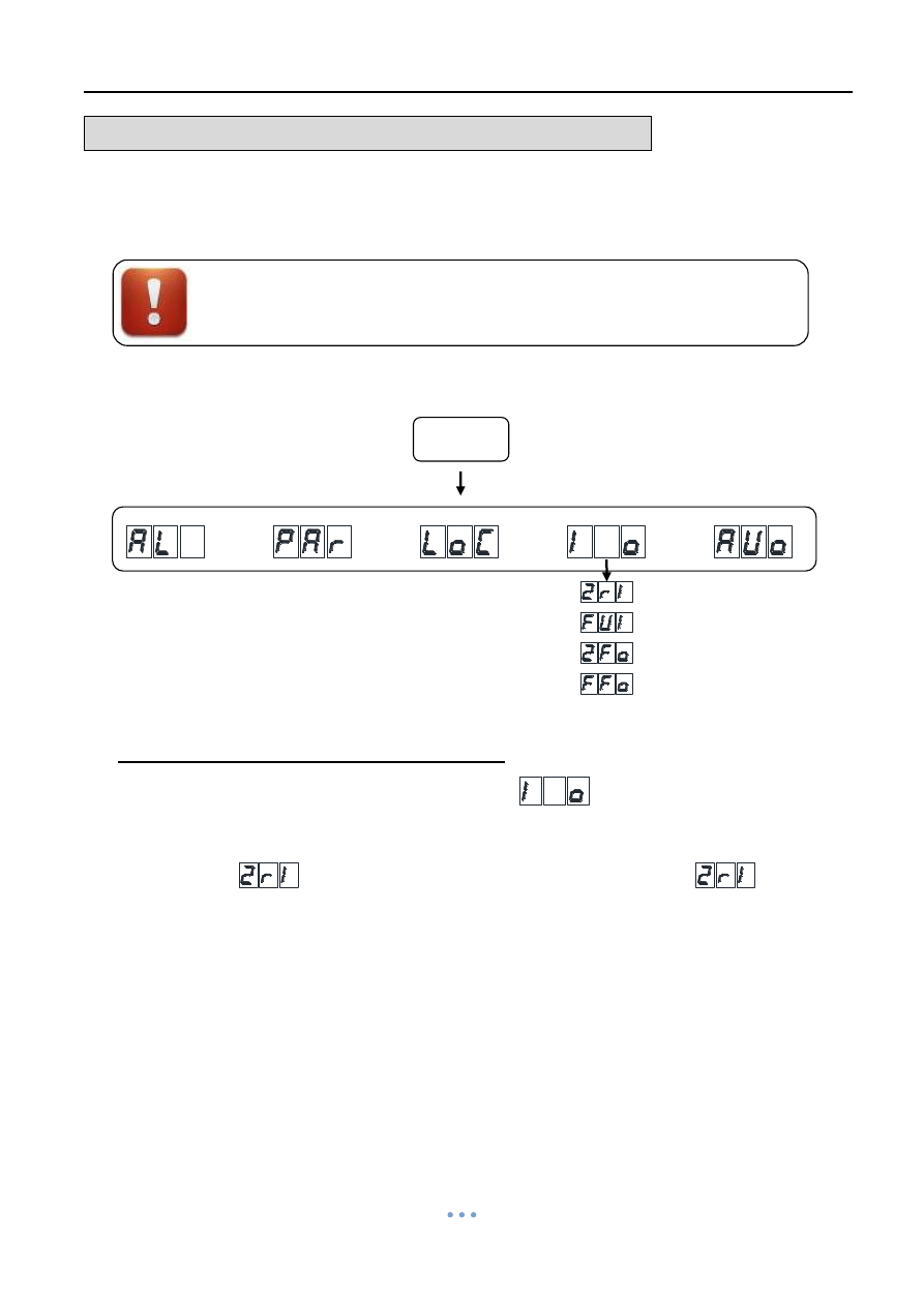
Quarter Turn Actuator 【OM series】
Sun Yeh Ele. Ind. Co., Ltd. | 2013.09
66
ADJUSTMENT
– Modulating Control Board
Part B: Suitable for OM-1、OM-A、OM-A-M (Option: MODBUS)
9. Signal Setting
If the travel setting could not satisfy your request, the signal is needed
to be adjusted separately, please follow the steps of signal setting.
Input signal setting for fully-closed position
a.
Press “MODE” several times until get into
, then press “SET” once to
enter signal setting mode.
b. Get into
, and keep pressing “SET” (around 3 sec) until
is
glittering.
c. Supply the input signal according to the dip switch setting (1V or 2V or 4mA).
d.
Press “SET” once and “MODE” twice to complete the input signal setting for
fully-closed position.
MODE
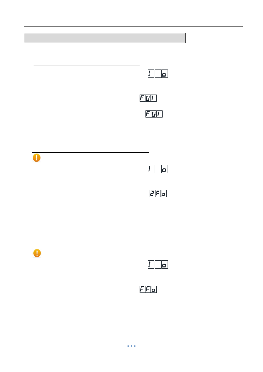
Quarter Turn Actuator 【OM series】
Sun Yeh Ele. Ind. Co., Ltd. | 2013.09
67
ADJUSTMENT
– Modulating Control Board
Part B: Suitable for OM-1、OM-A、OM-A-M (Option: MODBUS)
Input signal setting for fully-open position
a.
Press “MODE” several times until get into
, then press “SET” once to
enter signal setting mode.
b.
Adjust with “UP” and “DOWN” until get
.
c.
Keep pressing “SET” (around 3 sec) until
is glittering.
d. Supply the input signal according to the dip switch setting (5V or 10V or 20mA).
e.
Press “SET” once and “MODE” twice to complete the input signal setting for
fully-open position.
Output signal setting for fully-closed position
Install the ammeter or monitor to correspond to output signal setting
a.
Press “MODE” several times until get into
, then press “SET” once to
enter signal setting mode.
b.
Adjust with “UP” and “DOWN” until get into
.
c.
Keep pressing “SET” (around 3 sec).
d.
Adjust the output value with “UP” and “DOWN” until the value can fit with your
request.
e.
Press “SET” once and “MODE” twice to complete the output signal setting for
fully-closed position.
Output signal setting for fully-open position
Install the ammeter or monitor to correspond to output signal setting
a.
Press “MODE” several times until get into
, then press “SET” once to
enter signal setting mode.
b.
Adjust with “UP” and “DOWN” until get
.
c.
Keep pressing “SET” (around 3 sec).
d.
Adjust the output value with “UP” and “DOWN” until the value can fit with your
request.
e.
Press “SET” once and “Mode” twice to complete the output signal setting for
fully-open position.
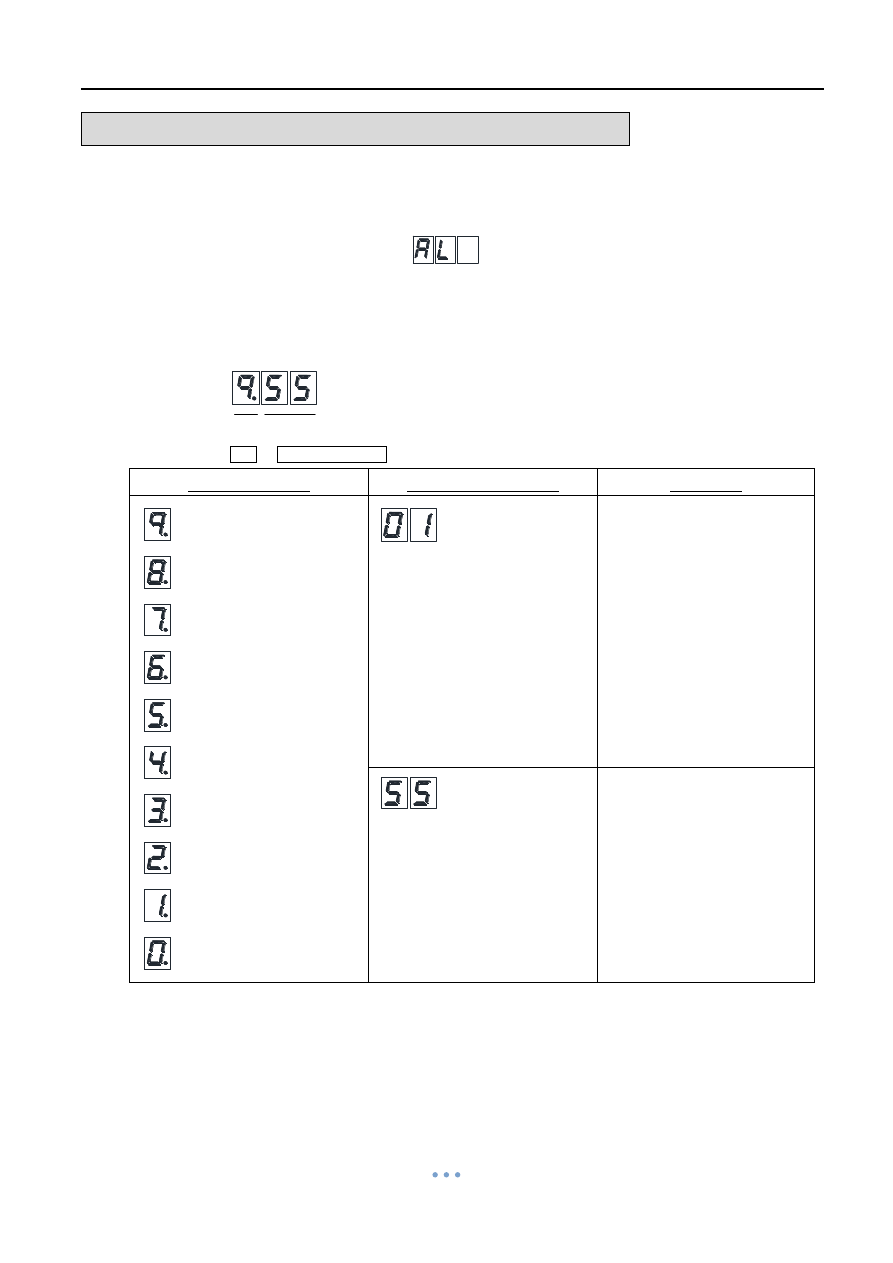
Quarter Turn Actuator 【OM series】
Sun Yeh Ele. Ind. Co., Ltd. | 2013.09
68
ADJUSTMENT
– Modulating Control Board
Part B: Suitable for OM-1、OM-A、OM-A-M (Option: MODBUS)
10. Warning Message
a.
Press ”MODE” once to get into
, then press “SET” once to get into
warning message.
b.
Adjust with ”UP” and ”DOWN” to review the history log of warning message.
↑ ↑
Item Warning Message
Item
(9,8,7…0)
Warning Message
Solution
Wrong Input signal.
a. Input signal fails.
b. Check if the input
signal and dip switch
setting are correct.
No abnormal records.
※ The latest data will stay with the item 9.
(The latest data)
(The oldest data)
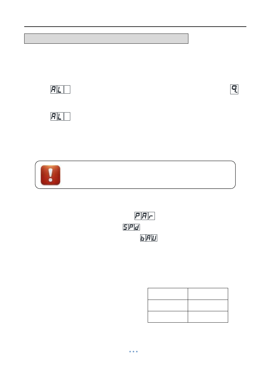
Quarter Turn Actuator 【OM series】
Sun Yeh Ele. Ind. Co., Ltd. | 2013.09
69
ADJUSTMENT
– Modulating Control Board
Part B: Suitable for OM-1、OM-A、OM-A-M (Option: MODBUS)
c. Example
If you want to check the latest data,
press “MODE” several times until get into
→ Press “Set” once → The LED display will show the latest data
.
If you want to check eighth data,
press “MODE” several times until get into
→ Press “SET” once →Press “DOWN” seven times and the LED
display will show the eighth data.
11. MODBUS Setting
Adjust the dip switch (SW) Pin1~
Pin5 to “ON” position
.
Baud rate setting
a. Press
”MODE” twice until get into
.
b. Press
”SET” once to get into
.
c. Press
”DOWN” ten times to enter to
.
d. Keep pressing
”SET” (around 3 sec) until the LED indicator is glittering to get into
setting mode.
e. Adjust with
”UP” and ”DOWN” to set baud rate for MODBUS. Adjust to your
demand value. (default valve #4)
f.
Press “SET” once to complete the setting.
Setting Value
Baud rate
4
9600
5
19200
MODBUS and modulating controller can not be operated at the same
time.

Quarter Turn Actuator 【OM series】
Sun Yeh Ele. Ind. Co., Ltd. | 2013.09
70
ADJUSTMENT
– Modulating Control Board
Part B: Suitable for OM-1、OM-A、OM-A-M (Option: MODBUS)
Station Setting
a.
Press “DOWN” once to get into
.
b.
Keep pressing “SET” (around 3 sec) until the LED indicator is glittering to get into
setting mode.
c.
Adjust with ”UP” and ”DOWN” to set the station. (Station Range:1~127, default
Station: 1)
d.
Press “Set” once to complete the setting.
Press ”Mode” four times to back to home page
.

Quarter Turn Actuator 【OM series】
Sun Yeh Ele. Ind. Co., Ltd. | 2013.09
71
TROUBLE SHOOTING
ON-OFF Controller
1. Motor does not operate and overheats
Possibilities
Solution
a. Supply power to #3、#4 simultaneously
(Parallel Connection).
b. The capacitor failed (whether the
surface of the capacitor deforms).
c.
Valve’s rubber is getting hardened or
the valve’s torque is excessive (it takes
longer time to reach fully-closed
position).
d. Foreign objects in the flow stream.
e.
Broken motor stem or bearing.
f.
The limit switch for fully-closed does
not trip.
a. Check the wiring (For coupling wiring,
refer to P48).
b. Replace to a new part.
c. Use hand-wheel for test or change to a
new valve.
d. Check if any obstructions
e.
Replace to a new part
s
f. Operate the actuator manually to
fully-closed position and confirm if the limit
switch trips.
2. The actuator is operated very well but the motor is hot.
Possibilities
Solution
a. Actuator operates too frequently
(Starting frequency is too high).
b. Overload.
c. Under or over rated voltage.
d.
Mechanical stops are reached by the
gear train at fully-open or fully-closed
position.
e.
Wrong power supply.
a. Change system bandwidth or replace
to a higher duty cycle actuator (refer to
P2).
b. This situation often happens after
operating for a long time. It is
suggested to replace to a new valve.
c. Check the supply circuit (refer to
P4~P5).
d. Reset the mechanical stops and cam
(TC1 & TC2) (refer to P49~P52).
e.
Check the power supply.
3. When operating two or more actuators simultaneously, the actuator works abnormally
some times and the motor is getting hot.
Possibilities
Solution
Parallel connection.
a. Check current values and install a
relay respectively.
(refer to wiring diagram P48)

Quarter Turn Actuator 【OM series】
Sun Yeh Ele. Ind. Co., Ltd. | 2013.09
72
TROUBLE SHOOTING
4. The valve can not fully-open or fully-closed by either power supply or hand-wheel.
Possibilities
Solution
a. The actuator does not mount with the
valve tightly during installation
process.
b. The torque of valve is larger than the
torque of actuator.
c. The set screw of the cam is loose.
d. The installing angle of actuator and
valve is not correct.
a. Contact technical department to solve
the problem.
b. Replace to a new valve or a larger
actuator.
c.
Readjust the mechanical stops and
limit switches (refer to P49~P52).
d. Check the angle of the valve and
actuator.
5. The capacitor is failed.
Possibilities
Solution
a. Overload (exceed the rated torque of
actuator).
b. Starting frequency is too high or
ambient temperature is too high.
c. Over service life.
a.
Replace to a new part. It’s suggested
to change a new valve or a larger
actuator.
b. Replace to a new part and change to
75% duty cycle actuator (refer to P2).
c. Check the capacitance and surface
every year.
Modulating Controller
1. The LED (LD5~LD9) is flashing after the operating check is completed.
Solution
Refer to P58.
2. The lamps on the modulating board are normal but the actuator can
’t work properly
during test or it only can turn to fully open/closed position.
Possibilities
Solution
The signal is connected oppositely
(means to signal failure).
Confirm if the input signal and the wiring
are correct (terminal #6 connects to
“–“ and terminal #7 connects to “+”).
3. Can not operate by modulating controller.
Possibilities
Solution
a. Faulty VR.
b.
The sector gear of the VR is loose
.
c. Wrong input signal.
d. Faulty modulating board.
a. Replace to a new VR.
b.
Remove the input signal wires.
Operate the actuator to fully-closed.
Then readjust the VR (refer to
P49~P51).
c.
Check if the input signal is correct
(refer to P49~P51).
d.
Send back to factory for inspection.

Quarter Turn Actuator 【OM series】
Sun Yeh Ele. Ind. Co., Ltd. | 2013.09
73
WARRANTY
Sun Yeh Ele. Co. Ltd warrants that for a period of twelve months from the date of
manufacture it will either repair or replace, at its option, any of its products which prove to be
defective in material or workmanship. This warranty does not cover damage resulting from
causes such as abuse, misuse, modification or tampering by users.
This warranty is extended only to the immediate purchaser of Sun Yeh product and is
not transferable.
To obtain service under this warranty, the purchaser must first acquire a return
authorization from Sun Yeh. Products must be returned to Sun Yeh under freight prepaid.
This warranty is in lieu of all other obligations, liabilities or expressed warranties. Any
implied warranties, including any implied warranty of merchantability are hereby expressly
excluded. In no event shall Sun Yeh be liable for special, incidental or consequential
damages arising in connection with the use of its products, or for any delay in the
performance of this warranty due to cause beyond its control.
Wyszukiwarka
Podobne podstrony:
więcej podobnych podstron