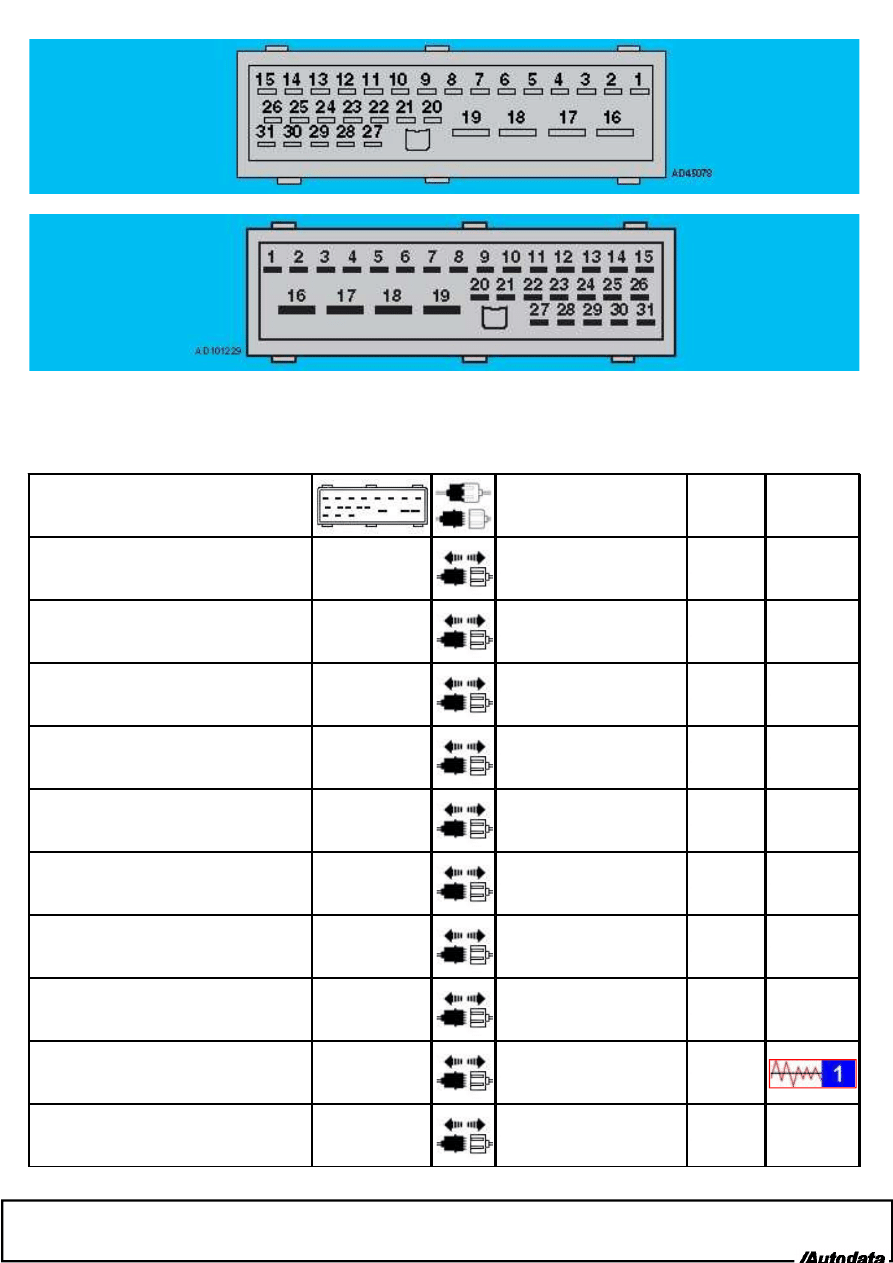
Terminal side
Wire side
NOTE: All component/circuit testing is carried out at the ABS control module harness multi-plug. Ensure suitable test
probes are used to avoid damage to the ABS control module harness multi-plug terminals.
Component/circuit description
Condition
Typical
value
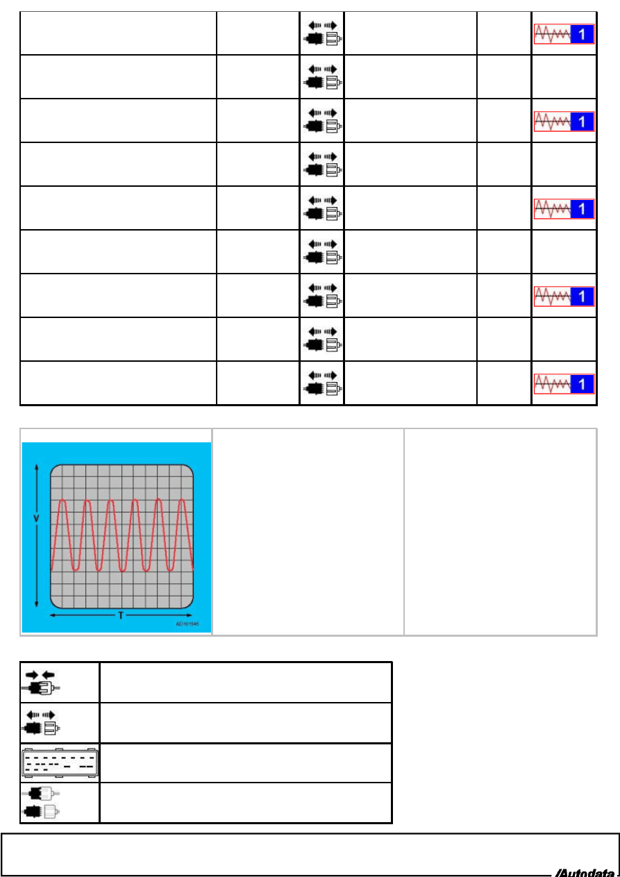
Wave form
Battery
17 & earth
Ignition OFF
11-14 V
Battery
18 & earth
Ignition OFF
11-14 V
Brake pedal position (BPP) switch
14 & earth
Ignition OFF - brake pedal
released
0 V
Brake pedal position (BPP) switch
14 & earth
Ignition OFF - brake pedal
depressed
11-14 V
Earth
16 & earth
0
W
Earth
19 & earth
0
W
Ignition switch
15 & earth
Ignition ON
11-14 V
Wheel speed sensor, left front
6 & 7
400-2300
W
Wheel speed sensor, left front
6 & 7
Wheel rotating
Wheel speed sensor, left rear
8 & 9
400-2300
W
Wheel speed sensor, left rear
8 & 9
Wheel rotating
Wheel speed sensor, right front - FWD with TCS
3 & 5
400-2300
W
Wheel speed sensor, right front
3 & 5
Wheel rotating
Wheel speed sensor, right front - FWD without
TCS/4x4
4 & 5
400-2300
W
Wheel speed sensor, right front
4 & 5
Wheel rotating
Wheel speed sensor, right rear - FWD with
TCS/4x4
1 & 2
400-2300
W
Wheel speed sensor, right rear
1 & 2
Wheel rotating
Wheel speed sensor, right rear - FWD without
TCS
1 & 3
400-2300
W
Wheel speed sensor, right rear
1 & 3
Wheel rotating
1. Analogue, AC, frequency modulated
Multi-plug connected
Multi-plug disconnected
ABS control module harness multi-plug terminals.
ABS control module harness multi-plug connected/disconnected.
Wyszukiwarka
Podobne podstrony:
więcej podobnych podstron