
MAST
H16.00-18.00XM-12EC (H400-450H-EC) [A214]
PART NO. 897989
4000 SRM 661

SAFETY PRECAUTIONS
MAINTENANCE AND REPAIR
• When lifting parts or assemblies, make sure all slings, chains, or cables are correctly
fastened, and that the load being lifted is balanced. Make sure the crane, cables, and
chains have the capacity to support the weight of the load.
• Do not lift heavy parts by hand, use a lifting mechanism.
• Wear safety glasses.
• DISCONNECT THE BATTERY CONNECTOR before doing any maintenance or repair
on electric lift trucks. Disconnect the battery ground cable on internal combustion lift
trucks.
• Always use correct blocks to prevent the unit from rolling or falling. See HOW TO PUT
THE LIFT TRUCK ON BLOCKS in the Operating Manual or the Periodic Mainte-
nance section.
• Keep the unit clean and the working area clean and orderly.
• Use the correct tools for the job.
• Keep the tools clean and in good condition.
• Always use HYSTER APPROVED parts when making repairs. Replacement parts
must meet or exceed the specifications of the original equipment manufacturer.
• Make sure all nuts, bolts, snap rings, and other fastening devices are removed before
using force to remove parts.
• Always fasten a DO NOT OPERATE tag to the controls of the unit when making repairs,
or if the unit needs repairs.
• Be sure to follow the WARNING and CAUTION notes in the instructions.
• Gasoline, Liquid Petroleum Gas (LPG), Compressed Natural Gas (CNG), and Diesel fuel
are flammable. Be sure to follow the necessary safety precautions when handling these
fuels and when working on these fuel systems.
• Batteries generate flammable gas when they are being charged. Keep fire and sparks
away from the area. Make sure the area is well ventilated.
NOTE:
The following symbols and words indicate safety information in this
manual:
WARNING
Indicates a condition that can cause immediate death or injury!
CAUTION
Indicates a condition that can cause property damage!

Mast
Table of Contents
TABLE OF CONTENTS
Safety Procedures When Working Near Mast..................................................................................................
General ...............................................................................................................................................................
Description .........................................................................................................................................................
Operation............................................................................................................................................................
Control Valve, Carriage/Attachment ............................................................................................................
Tilt Cylinders Repair .........................................................................................................................................
Remove ...........................................................................................................................................................
Disassemble ...................................................................................................................................................
Clean and Inspect ..........................................................................................................................................
Assemble ........................................................................................................................................................
Install .............................................................................................................................................................
Mast Repair ........................................................................................................................................................
Remove ...........................................................................................................................................................
Disassemble ...................................................................................................................................................
Clean and Inspect ..........................................................................................................................................
Assemble ........................................................................................................................................................
Install .............................................................................................................................................................
Lift Cylinders Repair .........................................................................................................................................
Description .....................................................................................................................................................
Remove ...........................................................................................................................................................
Disassemble ...................................................................................................................................................
Clean and Inspect ..........................................................................................................................................
Assemble ........................................................................................................................................................
Install .............................................................................................................................................................
Mast Operation Check .......................................................................................................................................
Lift and Tilt System Leaks Check.....................................................................................................................
Lift System.....................................................................................................................................................
Tilt System .....................................................................................................................................................
Tilt Cylinder Stroke and Backward Tilt Angle Adjustment............................................................................
Lift Chain Adjustments .....................................................................................................................................
Mast Adjustments..............................................................................................................................................
Bearing Blocks ...............................................................................................................................................
Wear Plates ....................................................................................................................................................
Carriage Adjustment .........................................................................................................................................
Troubleshooting..................................................................................................................................................
This section is for the following models:
H16.00-18.00XM-12EC (H400-450H-EC) [A214]
©2004 HYSTER COMPANY
i

"THE
QUALITY
KEEPERS"
HYSTER
APPROVED
PARTS

4000 SRM 661
Description
Safety Procedures When Working Near Mast
The following procedures must be used when inspect-
ing or working near the mast. Additional precautions
and procedures can be required when repairing or re-
moving the mast.
WARNING
Mast parts are heavy and can move. Distances
between parts are small.
Serious injury or
death can result if part of the body is hit by
parts of the mast or the carriage.
• Never put any part of the body into or under
the mast or carriage unless all parts are com-
pletely lowered or a safety chain is installed.
Also make sure that the power is off and the
key is removed. Put a DO NOT OPERATE tag
in the operator’s compartment.
• Be careful of the forks.
When the mast is
raised, the forks can be at a height to cause
an injury.
• Do NOT climb on the mast or lift truck at any
time. Use a ladder or personnel lift to work
on the mast.
• Do NOT use blocks to support the mast weld-
ments nor to restrain their movement.
• Mast repairs require disassembly and re-
moval of parts and can require removal of
the mast or carriage. Follow the repair pro-
cedures in the correct Service Manual for
the mast.
WHEN WORKING NEAR THE MAST ALWAYS:
1.
Lower the mast and carriage completely. Push
the lift/lower control lever forward and make
sure there is no movement in the mast. Make
sure that all parts of the mast that move are
fully lowered.
OR
2.
If parts of the mast must be in raised position,
install a safety chain to restrain the moving parts
of the mast. Connect moving parts to a part that
does not move. Follow these procedures:
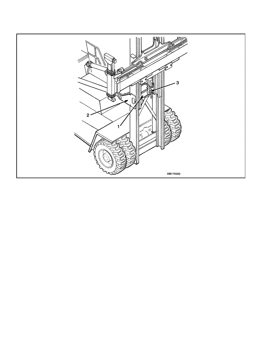
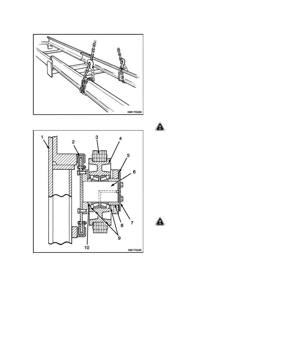
a. Put the mast in a vertical position.
b. Raise the mast to align the bottom cross-
member of the inner weldment with the
crossmember at the tilt cylinder mounts on
the outer weldment. See Figure 1.
c.
Use a 5/8 inch minimum safety chain with
a hook to fasten the weldments together so
that the inner weldment cannot lower. Make
sure the hooks are completely engaged with
a link in the chain.
d. Lower the mast until there is tension in the
safety chain. If the engine is running, stop
the engine. Apply the parking brake. In-
stall a DO NOT REMOVE tag on the safety
chain. Put a DO NOT OPERATE tag in the
operator’s compartment.
General
This section has the description, operation, and
repair procedures for the mast used on the
H18.00-16.00XM-12EC (H400-450H-EC) lift trucks.
Information on the lift cylinders, lowering control
valves, and tilt cylinders is included in this section.
Procedures for the carriage are included in the sec-
tion Empty Container Handling Attachment
5000 SRM 668.
Description
The mast has an outer and inner weldment. See Fig-
ure 2. The weldments are the vertical frames of the
mast. These weldments have the channels for the
load rollers and bearing blocks. The load rollers and
bearing blocks reduce the friction between the chan-
nels when the mast lifts and lowers.
The mast can tilt forward and backward. Tilt cylin-
ders are installed between the frame of the lift truck
and the outer weldment. The pivot mounts are at the
bottom of the outer weldment and connect the mast
to the lift truck. During the tilt operation the mast
rotates on the pivot pins in the frame.
1
Operation
4000 SRM 661
1.
INNER WELDMENT
2.
OUTER WELDMENT
3.
HOOK
Figure 1. Mast
Operation
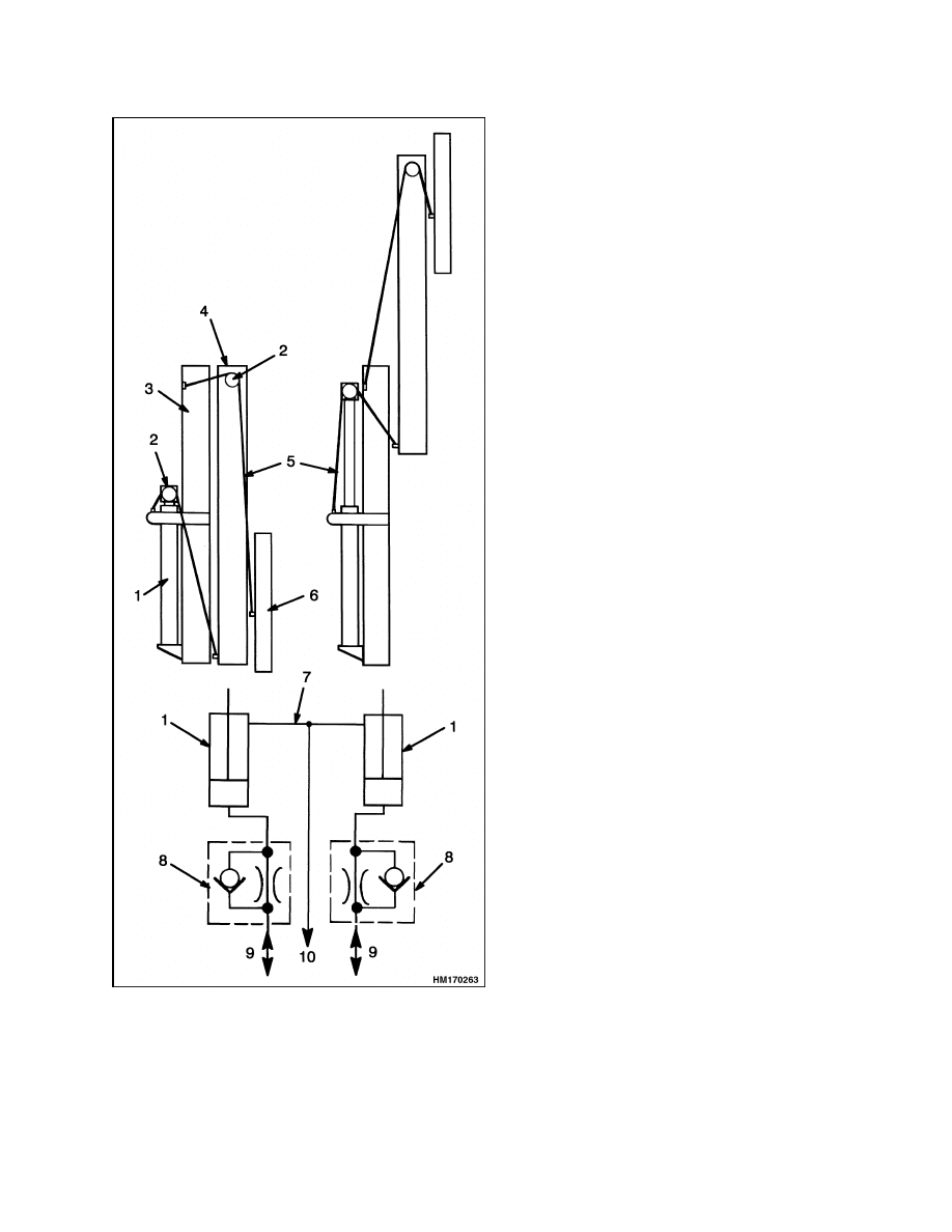
The outer weldment is connected to the lift truck by
the pivot pins and the tilt cylinders. See Figure 2.
The top of the outer weldment has two sets of bear-
ing blocks to control movement of the inner weld-
ment. The inner weldment has two load rollers and a
bearing block on each side. These parts travel along
the channels of the outer weldment and control the
movement between the inner and outer weldments.
The mast has two single-stage lift cylinders. The lift
cylinders are installed at the back of the mast. The
base of each lift cylinder is held to the mount plate at
the bottom of the outer weldment. The upper end of
each lift cylinder is held in position at the middle of
the outer weldment.
Two sets of lift chains control the movement of the in-
ner weldment and carriage. One set of lift chains is
connected between the center of the outer weldment
and the bottom of the inner weldment. The chains go
over the sheaves on the lift cylinders and lift the in-
ner weldment. Another set of lift chains is connected
between the top of the outer weldment and the car-
riage. The chains go up and over the chain sheaves
on the inner weldment and then connect to the car-
riage. These lift chains raise the carriage and attach-
ment as the inner weldment raises.
When the lift cylinders retract, the weight of the load,
the carriage, and the inner weldment push the oil
from the lift cylinders. The oil flows from the lift
cylinders, through the lowering control valves, main
control valve, and then to the hydraulic tank.
2
4000 SRM 661
Operation
Figure 2. Mast
Legend for Figure 2
1.
LIFT CYLINDER (2)
2.
CHAIN SHEAVE
3.
OUTER WELDMENT
4.
INNER WELDMENT
5.
LIFT CHAIN
6.
CARRIAGE/ATTACHMENT
7.
BREATHER LINE
8.
EXTERNAL LOWERING CONTROL VALVE
9.
FROM MAIN CONTROL VALVE
10. TO HYDRAULIC TANK
CONTROL VALVE,
CARRIAGE/ATTACHMENT
The hydraulic functions for the attachment are con-
trolled by the auxiliary control valve and the selec-
tor valves on the attachment. The operator actuates
the auxiliary control valve with switches in the oper-
ator’s compartment. The oil from the auxiliary con-
trol valve is used to move the auxiliary spool in the
main control valve. Oil from the auxiliary spool flows
to the selector valves for the functions at the attach-
ment. (The selector valves are installed on the at-
tachment.)
When the operator pushes a switch, one solenoid on
the auxiliary control valve and a solenoid on the se-
lector valve are energized at the same time. The so-
lenoid on the auxiliary control valve opens and lets
oil flow through the pilot line to move the auxiliary
spool. The opposite end of the auxiliary spool is open
to drain through the other solenoid on the auxiliary
control valve. When the auxiliary spool moves, it
lets oil from the hydraulic pump flow to the selector
valve as required. The selector valves send oil to the
sideshift, extend/retract, or lock pin cylinders.
3
Tilt Cylinders Repair
4000 SRM 661
Tilt Cylinders Repair
REMOVE
WARNING
The mast assembly and its components are
heavy. To avoid causing damage or an injury,
a lifting device must be used during all service
procedures. See Table 1 for the approximate
weight of the components.
WARNING
Before removing the tilt cylinder(s), tilt the
mast forward. Use a chain to hold the mast to
the frame and prevent the mast from moving
forward.
1.
Remove the relief valve from the port (rod side).
Disconnect the hydraulic lines at the tilt cylinder.
Install caps on the hydraulic lines and ports. Re-
move the clamps for the hydraulic lines.
2.
Connect a lifting device to the extension tube.
WARNING
Do not push the pivot pins out of the rod end
with your fingers.
3.
Remove the retainers for the pivot pins. Push the
pivot pins out of the rod end with a tool.
4.
Remove the retainer and pivot pin from the
frame mount. Lift the tilt cylinder from the lift
truck.
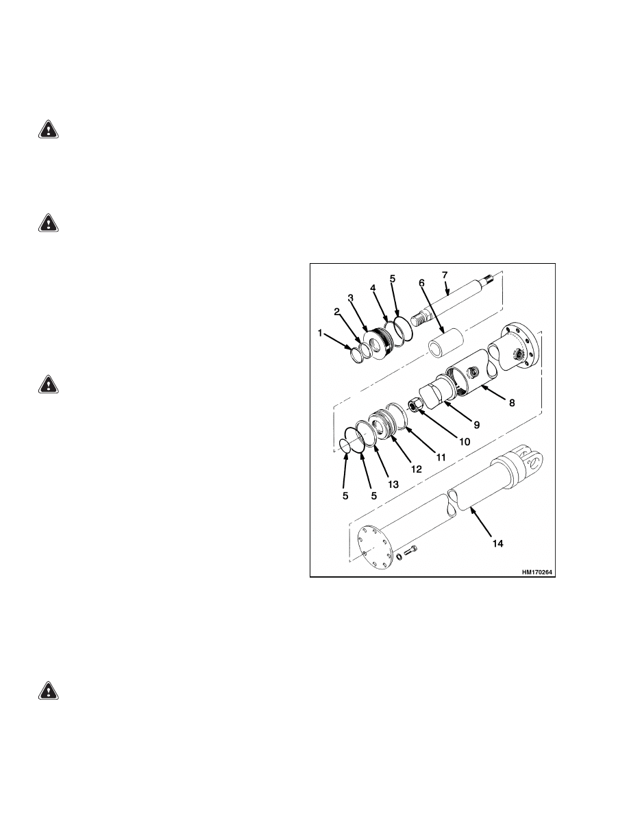
DISASSEMBLE
1.
Remove the extension tube from the tilt cylinder.
See Figure 3.
2.
Remove the rod end from the rod.
3.
Remove the retainer from the shell. Remove the
rod and piston assembly. Remove the spacer for
back tilt.
4.
Disassemble the tilt cylinder as necessary.
CLEAN AND INSPECT
WARNING
Cleaning solvents can be flammable and toxic
and can cause skin irritation.
When using
cleaning solvents, always follow the solvent
manufacturer’s recommended safety proce-
dures.
Compressed air can move particles so that they
cause injury to the user or to other personnel.
Make sure the path of the compressed air is
away from all personnel. Wear protective gog-
gles or a face shield to prevent injury to the
eyes.
Clean all parts in solvent and dry with compressed
air.
1.
WIPER SEAL
2.
ROD SEAL
3.
RETAINER
4.
BACKUP RING
5.
O-RING
6.
SPACER
7.
ROD
8.
SHELL
9.
BACK TILT SPACER
10. NUT
11. WEAR RING
12. PISTON
13. SEAL RING
14. EXTENSION TUBE
Figure 3. Tilt Cylinder
4

4000 SRM 661
Mast Repair
ASSEMBLE
NOTE:
Always use new seals and O-rings. Make sure
all parts are clean. Lubricate all parts with clean
hydraulic oil.
1.
Install the O-ring inside the piston bore. See Fig-
ure 3. Install the piston on the piston rod. Make
sure the O-ring is not damaged. Tighten the nut
on the piston rod to 1105 to 1140 N•m (815 to
840 lbf ft).
2.
Install the O-ring, seal ring, and wear ring on
the piston. The seal ring must be heated before
installation. After heating, it must be pushed
into its groove using a ring compressor. Let the
seal ring cool and return to its normal shape.
3.
Install the O-ring and the backup ring on the out-
side of the retainer. Make sure the O-ring is to-
ward the piston. Install the rod seal and wiper
seal in the retainer.
4.
Install the spacer on the rod. Install the retainer
on the piston rod. Install the spacer for back tilt
inside the cylinder shell, making sure the word
TOP is toward the piston. Install the piston and
rod assembly and the retainer in the cylinder
shell. Tighten the retainer to 610 to 675 N•m
(450 to 500 lbf ft).
5.
Install the extension tube on the tilt cylinder.
INSTALL
1.
Install the rod end on the rod as described in Tilt
Cylinder Stroke and Backward Tilt Angle Ad-
justment.
2.
Connect a lifting device to the extension tube.
Use the lifting device to move the tilt cylinder
into position on the lift truck. Lubricate the pivot
pin, then install it in the frame. Make sure the
grease fitting is toward the outside. Install the
retainer pin.
3.
Install the pivot pin at the mast.
Install the
retainer pin. Tighten the capscrews for the re-
tainer pins.
4.
Install the relief valve in the port (rod side). Con-
nect the hydraulic lines to the tilt cylinder. In-
stall the clamps for the hydraulic lines.
5.
Operate the tilt cylinders. Check for correct op-
eration and leakage. Adjust the tilt cylinders as
described in Tilt Cylinder Stroke and Backward
Tilt Angle Adjustment.
Mast Repair
REMOVE
WARNING
Lower the lift mechanism completely. Never
allow anyone under a raised carriage. Do not
put any part of your body in or through the
lift mechanism unless all parts of the mast
are completely lowered and the engine is
STOPPED.
Before making any repairs, use blocks and
chains on the inner weldment and carriage so
they cannot move. Make sure the moving parts
are attached to a part that does not move.
Do not try to locate hydraulic leaks by putting
hands on pressurized hydraulic components.
Hydraulic oil can be injected into the body by
pressure.
1.
Fully lower the inner weldment.
If the mast
must be disassembled, remove the carriage and
attachment. See the section Empty Container
Handling Attachment 5000 SRM 668.
2.
See Table 1 and connect a lifting device to the lift-
ing eyes on the outer weldment. Make sure the
lifting device has the capacity to hold the mast.
Raise the lifting device so that the mast has sta-
bility. See Figure 4.
3.
Clean the area around the hydraulic fittings for
the lift cylinders. Disconnect the hydraulic lines
at the bottom of the lift cylinders and put caps on
the open lines.
4.
Disconnect the header hoses and electrical cable.
See Figure 9.
5.
Put the mast in a vertical position. Remove the
capscrews from the mast pivot pins.
5
Mast Repair
4000 SRM 661
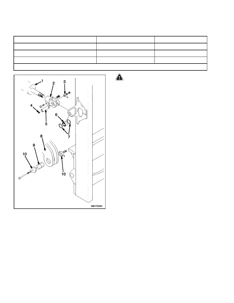
Table 1. Mast Weights
Unit
Lift Height
Weight
H16.00-18.00XM-12EC (H400-450H-EC)
16,200 mm (637.8 in.)
8,900 kg (19,621 lb)
H16.00-18.00XM-12EC (H400-450H-EC)
18,800 mm (740.2 in.)
9,400 kg (20,724 lb)
Carriage and Attachment
-
5,540 kg (12,214 lb)
NOTE:
The weight of the mast does not include the carriage or attachment.
1.
TILT CYLINDER
2.
ROD END
3.
ANCHOR PIN
4.
GREASE FITTING
5.
PIN
6.
SPHERICAL
BUSHING
7.
SNAP RING
8.
LIFT TRUCK
FRAME
9.
PIVOT PIN
10. CAP
Figure 4. Mast Mounting
WARNING
Do not push the pivot pins out of the rod end
with your fingers.
6.
Connect a lifting device to one of the tilt cylin-
ders. Remove the retainers for the pivot pins.
Push the pivot pins out of the rod end with a tool.
Lower the tilt cylinder so it rests on a block on the
fender. Use the same procedure for the other tilt
cylinder.
7.
Operate the lifting device and remove the mast
from the lift truck. Put the mast in a position so
the crossmembers are facing up.
DISASSEMBLE
1.
Remove the pins for the lift chains at the chain
anchors. See Figure 8. Remove both sets of lift
chains. Remove the capscrew and washers from
the bottom of each lift cylinder.
2.
Connect a lifting device to the lift cylinder. Re-
move the chain sheave assembly from the lift
cylinder. Disconnect the lift cylinder from the
mount. Carefully pull the lift cylinder down from
the outer weldment and remove it from the mast.
See Lift Cylinders Repair for disassembly and as-
sembly instructions.
3.
Remove the bearing block assemblies at the top
of the outer weldment. Remove the wear plates
from the outer weldment.
4.
Slide the inner weldment halfway out of the
outer weldment. Connect a lifting device to the
center of the inner weldment.
See Figure 5.
Slide the inner weldment completely out of the
outer weldment.
6
4000 SRM 661
Mast Repair
Figure 5. Inner Weldment Removal
1.
OUTER
WELDMENT
2.
GUIDE BEARING
3.
LIFT CHAIN
4.
CHAIN SHEAVE
5.
SHIMS
6.
PIN
7.
RETAINER
8.
OUTER SPACER
9.
INNER SPACER
10. SHIELD
Figure 6. Chain Sheave Arrangement
5.
Remove the load rollers as necessary for cleaning
and repair. Remove the bearing blocks.
6.
Remove and disassemble the chain sheaves as
necessary for cleaning and repair. See Figure 6.
CLEAN AND INSPECT
1.
Inspect the sheaves and load rollers for wear or
damage. DO NOT use steam to clean the lift
chains, sheaves, or load rollers. The bearings in
the load rollers are sealed and lubricated. Lubri-
cate the bearings in the sheaves and load rollers
with multipurpose grease before installation.
The parts of the chain sheaves and load rollers
can be replaced.
WARNING
Cleaning solvents can be flammable and toxic
and can cause skin irritation.
When using
cleaning solvents, always follow the recom-
mendations of the manufacturer.
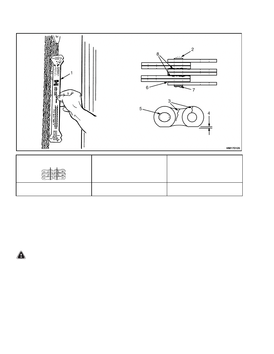
2.
Clean the lift chains with solvent. Inspect the lift
chains for wear or damage. See Figure 7. A lift
chain becomes longer when it is worn. If a chain
is 3% longer than a new lift chain, the lift chain
must be replaced. Use a chain scale to measure
the chains. If a chain scale is not available, check
the lift chains with the measurements given in
Figure 7. Lubricate the chains with SAE 30 en-
gine oil. The best procedure is to remove the
chains from the lift truck and soak them in oil.
WARNING
Never replace just the worn section of a chain.
Replace the complete chain. Never replace just
one chain of a chain pair. Replace both chains.
3.
Inspect the chain anchors and pins. Replace any
parts that are worn or damaged.
4.
Clean the mast with steam or solvent.
5.
Inspect the sliding and rolling surfaces for dam-
age. Inspect all welds for cracks.
7
Mast Repair
4000 SRM 661
Pitch
Total Length of 20 Links
(Pitch) of New Chain
Wear Limit
The Maximum Length of
20 Links
44.5 mm (1.75 in.)
50.8 mm (2.00 in.)
889.0 mm (35.0 in.)
1016.0 mm (40.0 in.)
915.7 mm (36.1 in.)
1046.5 mm (41.2 in.)
NOTE: INSTRUCTIONS FOR MEASURING CHAIN WEAR ARE SHOWN ON CHAIN WEAR SCALE.
1.
CHAIN WEAR SCALE
2.
WORN PIN
3.
CRACKS
4.
EDGE WEAR
5.
HOLE WEAR
6.
LOOSE LEAVES
7.
DAMAGED PIN
8.
RUST
Figure 7. Lift Chains Check
ASSEMBLE
WARNING
DO NOT weld on any part of the mast assembly
or carriage. Get information from your dealer
for Hyster lift trucks before welding on the
mast.
NOTE:
The shims for the bearing blocks and wear
plates keep the inner and outer weldments parallel
and give correct clearance. During assembly, the lo-
cation of the shims will be approximately the same as
they were before disassembly. Check the clearance
and adjust the shims for wear or changes because of
repairs.
1.
Install the load rollers as follows (see Figure 8):
a. Lubricate the bearings with multipurpose
grease.
8

4000 SRM 661
Mast Repair
b. Install the load roller on the shaft. Install the
retainer and capscrews. (Do not add shims at
this time.) Tighten the capscrews to 26 N•m
(19 lbf ft).
c.
Measure the clearance between the retainer
and the outer bearing. Add shims under the
retainer so there will be zero clearance. In-
stall the retainer and tighten the capscrews
to 53 N•m (39 lbf ft). Check that the load
roller rotates freely.
2.
Install the chain sheaves in the inner weldment
as follows:
a. Lubricate the bearings with multipurpose
grease, then install the bearings and seals
in the chain sheaves.
b. Install the chain sheave and inner spacer in
the bracket, then install the shaft. Install
outer spacer and the retainer. (Do not add
shims at this time.) Tighten the capscrews
to 26 N•m (19 lbf ft).
c.
Measure the clearance between the retainer
and the bracket. Add shims under the re-
tainer so there will be zero clearance. In-
stall the retainer and tighten the capscrews
to 53 N•m (39 lbf ft). Check that the chain
sheave rotates freely.
3.
Install the chain sheaves in the lift cylinder
mounts as follows:
a. Lubricate the bearings with multipurpose
grease.
b. Install the chain sheave and inner spacer in
the bracket, then install the shaft. See Fig-
ure 6. Install outer spacer and the retainer.
(Do not add shims at this time.) Tighten the
capscrews to 26 N•m (19 lbf ft).
c.
Measure the clearance between the retainer
and the bracket. Add shims under the re-
tainer so that there will be zero clearance. In-
stall the retainer and tighten the capscrews
to 53 N•m (39 lbf ft). Check that the chain
sheave rotates freely.
4.
Install the mounts for the bearing blocks on the
inner weldment. Tighten the capscrews for the
mounts to 53 N•m (39 lbf ft). Install the bearing
blocks and shims.
5.
Connect a lifting device to the center of the inner
weldment. Put the load rollers into the end of
the outer weldment. Slide the inner weldment
into the outer weldment until the inner and outer
weldments are aligned. See Figure 5
6.
Install the bearing blocks and shims at the top
of the outer weldment. Install the nuts and bolts
for the bearing blocks. Lubricate the surface of
the bearing blocks with multipurpose grease.
7.
Lubricate the back of the inner weldment for its
entire length with multipurpose grease. Install
the wear plates and the shims at the back of the
outer weldment.
8.
Adjust the bearing blocks and wear plates as de-
scribed in Mast Adjustments.
9.
Lubricate the channels for the lift cylinder guides
with multipurpose grease. Use a lifting device to
install the lift cylinders. Carefully install the lift
cylinder guides in the channels. Install the lift
cylinder in the mount and install the washer and
capscrew.
10. Make sure the lowering control valves are in-
stalled at the bottom of both lift cylinders.
11. Connect the lift chains between the outer weld-
ment and the inner weldment. Connect the lift
chains for the carriage at the top of the outer
weldment. Attach wires between the ends of the
lift chains and the crossmember on the inner
weldment to control the lift chains during instal-
lation of the mast.
9
Mast Repair
4000 SRM 661
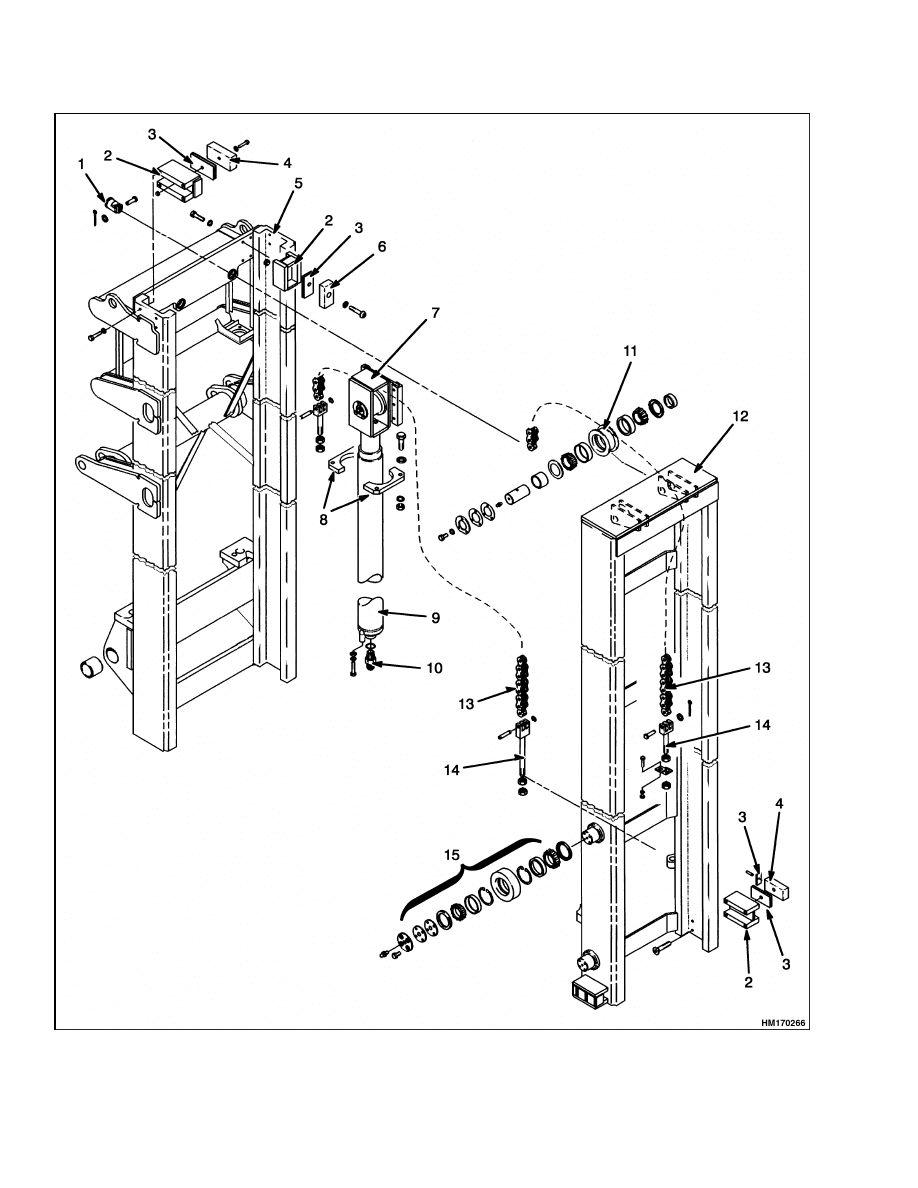
Figure 8. Mast
10

4000 SRM 661
Mast Repair
Legend for Figure 8
1.
CHAIN ANCHOR
2.
BRACKET
3.
SHIMS
4.
BEARING BLOCK
5.
OUTER WELDMENT
6.
WEAR PLATE
7.
LIFT CYLINDER GUIDE
8.
RETAINERS
9.
LIFT CYLINDER
10. LOWERING CONTROL VALVE
11. CHAIN SHEAVE
12. INNER WELDMENT
13. LIFT CHAIN
14. CHAIN ANCHOR
15. LOAD ROLLER ASSEMBLY
INSTALL
1.
Make sure the bushings and snap rings for the
tilt cylinder pins are installed in the frame and
outer weldment. See Figure 4. Install the tilt
cylinders to the frame mounts. Install the tilt
pins and anchor pins. Make sure the grease fit-
tings are toward the outside of the lift truck.
2.
See Table 1 and connect a lifting device to the top
of the mast assembly. Make sure the inner and
outer weldments are fastened together. Make
sure the chains do not damage any of the hy-
draulic lines or other parts.
3.
Raise the mast assembly to a vertical position.
Move the mast assembly into position on the lift
truck.
4.
Lubricate the mast pivot pins and bushings with
multipurpose grease. Install the mast pivot pins
with the grease fitting toward the center of the
lift truck.
5.
Connect the tilt cylinders to the outer weldment.
Install the tilt pins and anchor pins. Make sure
the grease fittings are toward the outside of the
lift truck.
6.
Install the carriage and attachment as described
in the section Empty Container Handling At-
tachment 5000 SRM 668.
7.
Connect the hydraulic lines to the mast assem-
bly. Connect the header hoses and electrical ca-
ble as shown in Figure 9.
8.
Adjust the lift chains, carriage, and tilt cylinders
as described in Lift Chain Adjustments, Carriage
Adjustment, and Tilt Cylinder Stroke and Back-
ward Tilt Angle Adjustment.
11
Mast Repair
4000 SRM 661
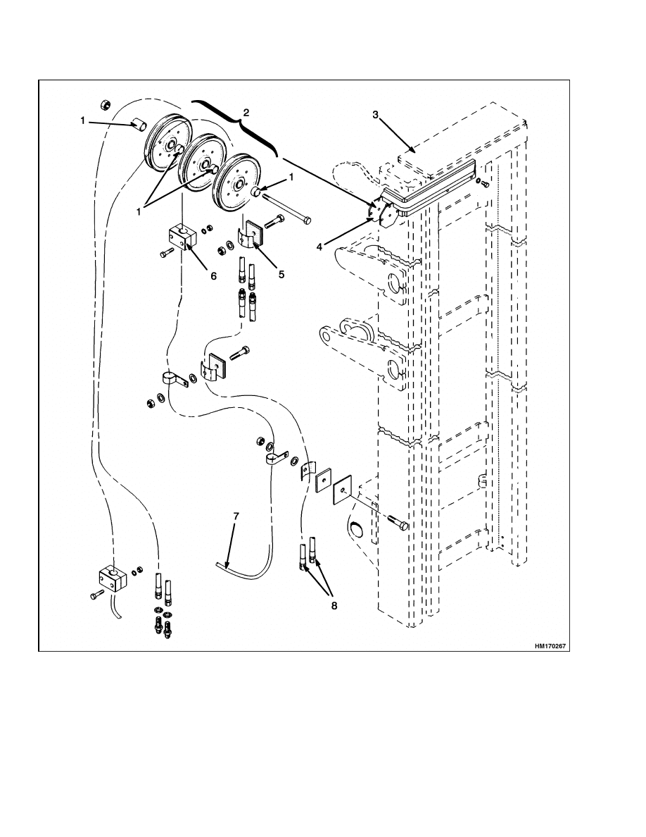
1.
SPACER
2.
SHEAVES
3.
INNER WELDMENT
4.
SHEAVE BRACKET
5.
HOSE CLAMP
6.
HARNESS CLAMP
7.
WIRE HARNESS
8.
HEADER HOSES
Figure 9. Header Hoses
12
4000 SRM 661
Lift Cylinders Repair
Lift Cylinders Repair
DESCRIPTION
The mast has two piston-type lift cylinders. The lift
cylinders for these lift trucks are single-action hy-
draulic cylinders. When hydraulic oil enters one end
of the cylinder, the hydraulic force extends the rod.
When the oil is allowed to drain from the cylinder, the
weight of the attachment and inner weldment cause
the cylinder rods to retract.
During lifting, oil from the main control valve flows
to the bottom of the lift cylinders. As the cylinder
rods extend, the air and any leakage on top of the
pistons is forced through the breather line back to
the hydraulic tank.
The lift cylinders have a single-lip seal on the piston
to prevent hydraulic oil leaks past the piston and re-
tainer. During operation, some hydraulic oil can leak
past the piston area to the rod end of the lift cylin-
der. Small internal leaks are permitted if the inter-
nal leak rate of the hydraulic system is not greater
than the specification.
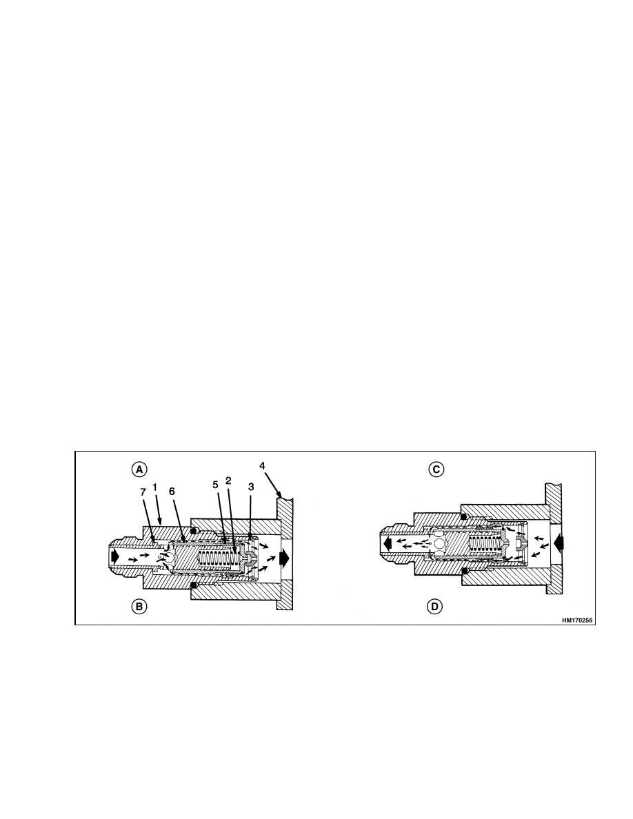
A lowering control valve (see Figure 10) is installed
in the base of the lift cylinders. The lowering con-
trol valve permits easy entry of hydraulic oil into the
cylinders, but gives a restriction when the rods re-
tract. This restriction controls the maximum speed
at which the attachment can be lowered.
The lowering control valve is shown in Figure 10.
The position of the orifice sleeve is controlled by oil
flow. The position of the plunger is controlled by oil
pressure and spring tension. During lifting, oil enter-
ing the cylinder goes through the center of the main
sleeve to the large holes. The oil continues between
the plunger and bore to move the orifice sleeve to the
end of the plunger. The flange of the orifice sleeve
is then aligned with the large part of the bore in the
body. This alignment lets the oil flow around the ori-
fice sleeve to the inlet port of the cylinder.
During the lowering operation, oil from the cylinder
moves the orifice sleeve. The sleeve moves away from
the larger area of the bore in the valve body. This
movement makes a restriction to the oil flow. When
the pressure increases, the plunger begins to move
against the spring. The movement begins to close the
openings of the large holes in the main sleeve. Ad-
ditional pressure will push the plunger against the
main sleeve to close the large holes completely. All
the oil must go through the small holes to the center
of the main sleeve. This restriction limits cylinder
rod lowering to a maximum controlled speed.
A. FREE FLOW
B. LIFTING
C. RESTRICTED FLOW
D. LOWERING
1.
VALVE BODY
2.
SPRING
3.
WASHER
4.
LIFT CYLINDER
5.
ORIFICE SLEEVE
6.
PLUNGER
7.
MAIN SLEEVE
Figure 10. Lowering Control Valve
13
Lift Cylinders Repair
4000 SRM 661
REMOVE
Remove the lift cylinders while disassembling the
mast. See the procedures in Mast Repair, Disassem-
ble.
DISASSEMBLE
NOTE: The most common maintenance problem is
the repair of oil leaks. If the bore of the shell of the
lift cylinder is damaged and cannot be repaired, the
lift cylinder must be replaced.
WARNING
The lift cylinders are very heavy. Use slings
and a lifting device to handle and disassemble
the lift cylinders.
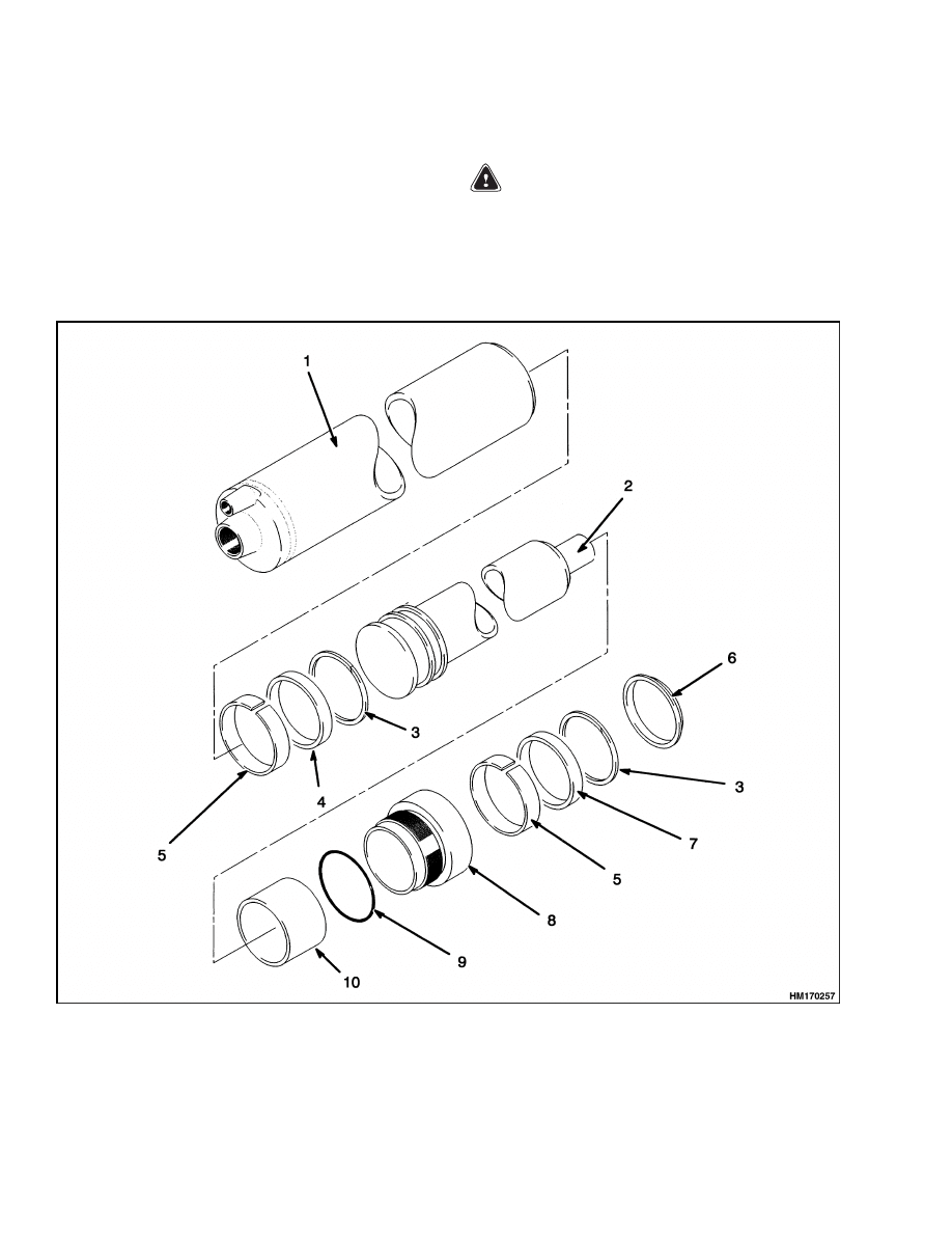
1.
Loosen the retainer with a spanner. See Fig-
ure 11. Remove the retainer from the shell.
1.
SHELL
2.
ROD AND PISTON
3.
BACKUP RING
4.
PISTON SEAL
5.
WEAR RING
6.
WIPER
7.
ROD SEAL
8.
RETAINER
9.
O-RING
10. SPACER
Figure 11. Lift Cylinder
14

4000 SRM 661
Mast Operation Check
2.
Carefully pull the rod and piston assembly from
the shell. Drain the hydraulic oil into a container.
3.
Remove and discard the O-rings, seals, wiper
ring, and wear ring.
CLEAN AND INSPECT
WARNING
Cleaning solvents can be flammable and toxic
and can cause skin irritation.
When using
cleaning solvents, always follow the recom-
mendations of the manufacturer.
Clean all the parts in solvent. Check the sliding sur-
faces for damage. Repair or replace any damaged
parts.
ASSEMBLE
NOTE:
• Lubricate all internal parts of the cylinder with
clean hydraulic oil during assembly.
• Use new O-rings, seals, and wear rings.
• Make sure the single-lip seal assemblies are in-
stalled with the O-ring toward the base of the cylin-
der.
CAUTION
An important step in assembling cylinders is
the correct installation of the seals. Seals that
are not installed correctly can be damaged and
cause leaks. Special tools are available from
Hyster Parts and Service.
See Parts-Service
Gram L-A-2 (Latest Revision) for the available
tools.
1.
Install the backup ring, single-lip seal, and wear
ring on the piston assembly. See Figure 11.
2.
Install the spacer on the rod.
3.
Use shim material as a guide to move the sin-
gle-lip seal past the threads of the shell. Care-
fully push the piston and rod assembly into the
shell. Release the clamp on the seal when the
seal travels past the threads of the shell.
4.
Install the wiper, backup ring, single-lip seal,
and wear ring in the retainer. Install the O-ring
on the outside of the retainer.
5.
Carefully install the retainer on the rod. En-
gage the threads and tighten the retainer in the
shell. The correct torque is 550 to 625 N•m (400
to 450 lbf ft). Use a correct spanner. Do not hit
the retainer with a hammer and driver.
6.
Install the lowering control valve. Make sure the
special washer and the spring are installed cor-
rectly in the base of the cylinders. A wrong in-
stallation can cause the load to lower too fast.
INSTALL
Install the lift cylinders while assembling the mast.
See the procedures in Mast Repair, Assemble.
Mast Operation Check
WARNING
Lower the lift mechanism completely. Never
allow anyone under a raised carriage. Do not
put any part of your body in or through the
lift mechanism unless all parts of the mast
are completely lowered and the engine is
STOPPED.
Before making any repairs, use blocks and
chains on the inner and outer weldments and
carriage so they cannot move. Make sure the
moving parts are attached to a part that does
not move.
Do not try to locate hydraulic leaks by putting
hands on pressurized hydraulic components.
Hydraulic oil can be injected into the body by
pressure.
1.
Check for leaks in the hydraulic system. Check
the condition of the hydraulic hoses and tubes.
2.
Slowly raise and lower the mast several times
without a load. The mast components must raise
and lower smoothly in the correct sequence.
15
Lift and Tilt System Leaks Check
4000 SRM 661
NOTE:
Some parts of the mast move at different
speeds during raising and lowering.
3.
The inner weldment and the carriage must lower
completely.
4.
Check that the controls for the attachment oper-
ate the functions of the attachment. (See symbols
by each of the controls.) Make sure all of the hy-
draulic lines are connected correctly and do not
leak.
Lift and Tilt System Leaks Check
LIFT SYSTEM
1.
Slowly raise and lower the mast several times
without a load. Pick up a container and raise
and lower it several times. Lower the container
and tilt the mast forward and backward several
times. Check for leaks, and repair as necessary.
2.
Raise the carriage 1 m (3 ft). If the carriage low-
ers slowly with the control valve in a Neutral po-
sition, there are leaks inside the hydraulic sys-
tem. The maximum speed that the carriage is
allowed to lower is shown in Table 2.
3.
Check the lift cylinder for internal leaks. Re-
move the load from the attachment. Install a
gate valve in each of the supply lines between the
main control valve and the mast. Pick up the con-
tainer again. Raise the carriage 1 m (3 ft). Close
both gate valves. If the carriage or inner weld-
ment lowers slowly, the seals in the lift cylinders
have leaks.
4.
If the carriage does not move, open both gate
valves and check the movement again. If the car-
riage lowers when the gate valves are open, check
for leaks in the hydraulic lines and fittings. If no
leaks are found, the main control valve can have
a damage. Remove the load.
TILT SYSTEM
1.
Pick up a container and raise the carriage ap-
proximately 30 cm (12 in.). Slowly tilt the mast
forward. If the mast continues to slowly tilt for-
ward when the control valve is in a Neutral posi-
tion, there are leaks inside the hydraulic system.
The maximum speed that the mast is allowed to
tilt forward is shown in Table 2.
2.
If the leak rate is greater than specified, remove
the load. Install a gate valve between the port at
the front of each tilt cylinder and the hydraulic
line.
Pick up the container again.
Close one
valve. If the mast tilts slowly forward, the cylin-
der connected to the closed gate valve has seals
that leak. Check the other cylinder using the
same procedure.
3.
If the mast does not move, open one of the gate
valves and check for movement again.
If the
mast moves forward with the valve open, check
for leaks in the hydraulic lines or fittings. Check
the other tilt cylinder using the same procedure.
If no leaks are found, the main control valve can
have damage. Remove the load.
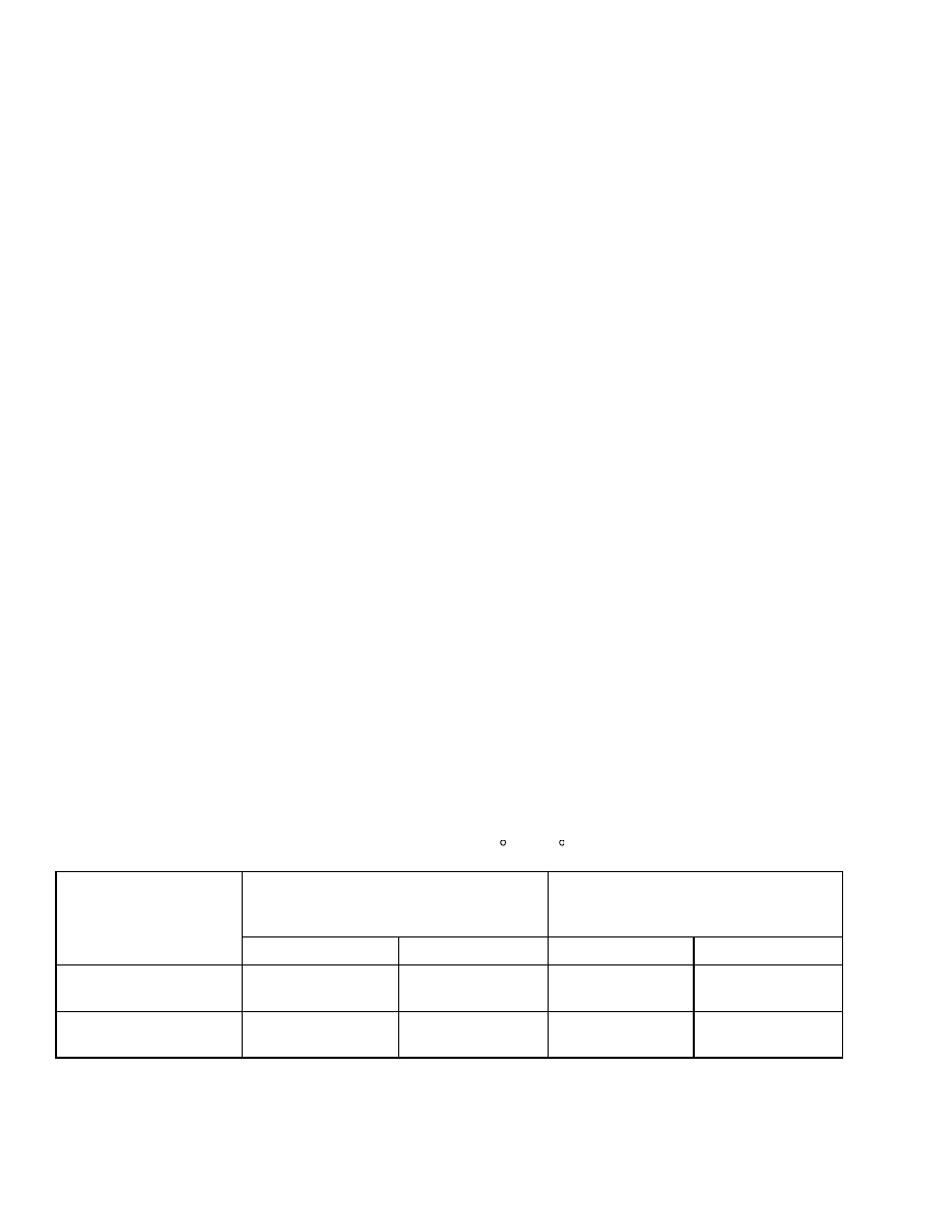
Table 2. Allowable Mast Movement from Internal Leakage (Hydraulic
Oil Temperature at 49 C (120 F)
Maximum Vertical Movement
at Carriage
Maximum Horizontal Movement
at Cylinder
Tilt Cylinder Stroke
Unit
mm/5 minutes
in./5 minutes
mm/5 minutes
in./5 minutes
H16.00XM-12EC
(H400H-EC)
37
1.5
3.1
0.12
H18.00XM-12EC
(H450H-EC)
37
1.5
3.1
0.12
16
4000 SRM 661
Tilt Cylinder Stroke and Backward Tilt Angle Adjustment
Tilt Cylinder Stroke and Backward Tilt Angle Adjustment
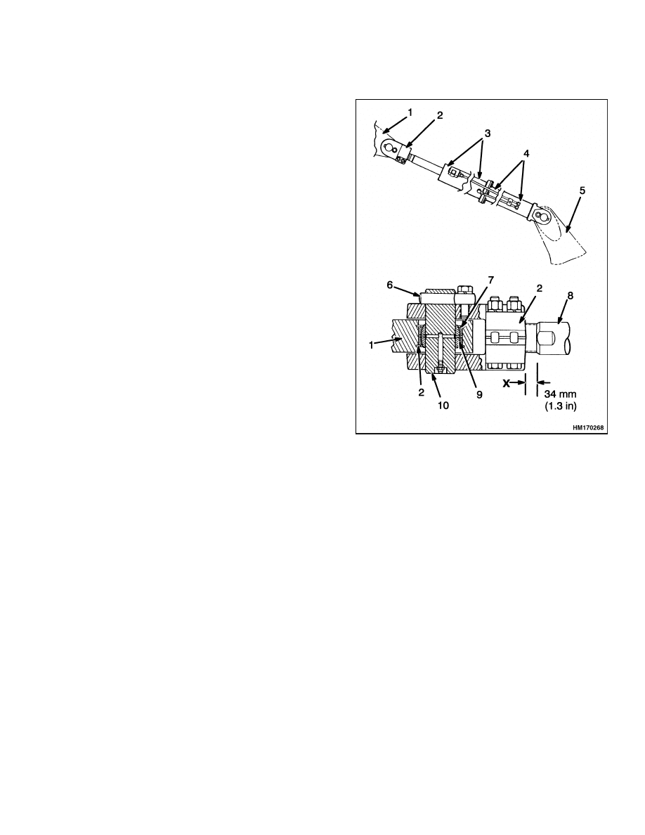
1.
Check that the distance from the rod end to the
shoulder of the rod is 34 mm (1.3 in.). See Fig-
ure 12.
2.
Slowly tilt the mast backward until one rod is
against its stop. On the opposite tilt cylinder,
loosen the capscrews on the rod end and turn the
cylinder rod out of the rod end until both rods
stop at the same time. If necessary, loosen a fit-
ting on the tilt cylinder to release hydraulic pres-
sure in the cylinder.
3.
Repeat the procedure to make sure the cylin-
der rods stop at the same time within 1.0 mm
(0.04 in.). Check that the tilt angles are correct
as specified on the nameplate of the lift truck.
When adjustments are complete, dimension X
must not be more than 53 mm (2.1 in.).
4.
After the adjustments, tighten the capscrews on
the rod end to 165 N•m (122 lbf ft).
1.
MAST
2.
ROD END
3.
TILT CYLINDER
4.
EXTENSION TUBE
5.
FRAME
6.
ANCHOR PIN
7.
SNAP RING
8.
CYLINDER ROD
9.
SPHERICAL
BEARING
10. PIN
Figure 12. Tilt Cylinder Installation
17
Lift Chain Adjustments
4000 SRM 661
Lift Chain Adjustments
When correctly adjusted:
• The tension will be the same on each chain of the
chain set. Check tension by pushing on both chains
at the same time.
• The chain length will be correct.
• The chains must travel freely through the complete
cycle.
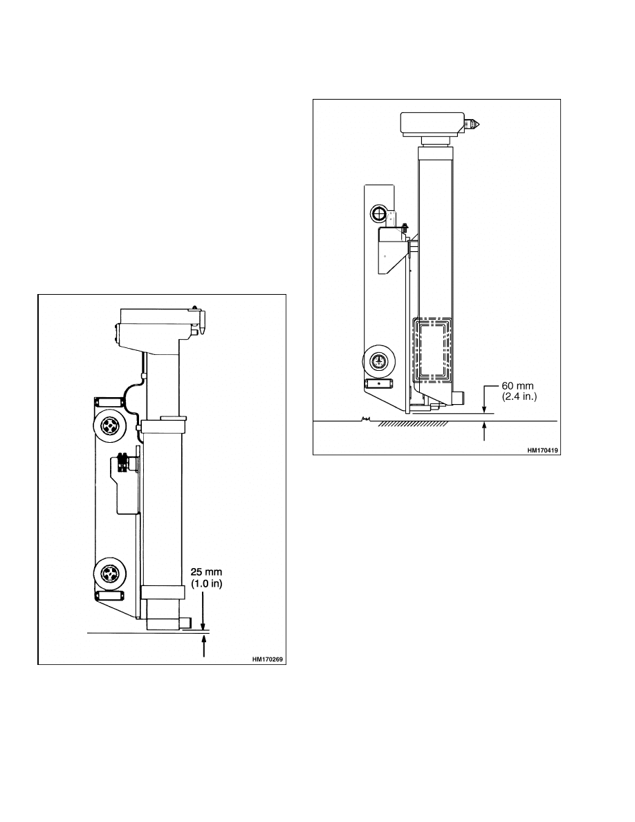
Put the lift truck on a flat, level surface. Put the mast
in a vertical position. Lower the carriage and attach-
ment. Check the clearance between the bottom of the
attachment and the surface (floor). If the adjustment
is not correct, adjust the chain anchors at the car-
riage. Make sure each anchor is adjusted the same
amount. See Figure 13 and Figure 14.
Figure 13. Lift Chain Adjustment (568)
Figure 14. Lift Chain Adjustment (570)
18

4000 SRM 661
Carriage Adjustment
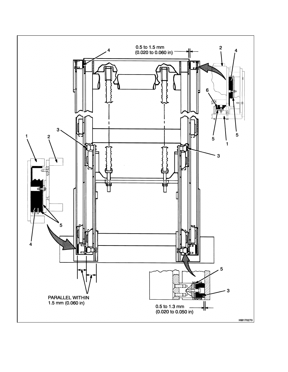
Mast Adjustments
BEARING BLOCKS
1.
The bearing blocks control the alignment of the
inner weldment with the outer weldment. To de-
crease wear, the vertical channels must be paral-
lel to each other. See Figure 15.
2.
When installing the bearing blocks, be sure to lu-
bricate the face of the bearing block with multi-
purpose grease. Adjust the bearing blocks as fol-
lows:
a. Use a crowbar to move the inner weldment
from side to side to measure the amount of
movement. Repeat in a minimum of three
different positions of the inner and outer
weldments.
b. Change the shim arrangements as needed.
Slide the inner weldment all the way to the
top and bottom to find the tightest position.
Be sure to check the clearance at the back
of the bottom bearing block.
The correct
clearance between the bearing blocks and
the channels at the tightest position is 0.5 to
1.5 mm (0.02 to 0.06 in.).
WEAR PLATES
Adjust the wear plates at the top of the outer weld-
ment as follows:
1.
Adjust the wear plates so the clearance at the
tightest position on the inner weldment is 0.5 to
1.5 mm (0.02 to 0.06 in.).
2.
Insert shims between the wear plate and the
bracket on the outer weldment as necessary.
Carriage Adjustment
1.
Find the tightest fit between the bearing blocks
and the channels of the inner weldment. See Fig-
ure 15.
2.
The maximum clearance between the bearing
block and the inner channel is 0.5 to 1.3 mm
(0.020 to 0.050 in.) at the point of the tightest
fit. When installing the bearing blocks, be sure
to lubricate the face of the bearing block with
multipurpose grease.
3.
Adjust the shim arrangement for each bearing
block. If necessary, a maximum of five shims
can be added between the bearing block and the
bracket. If more than five shims are required, re-
place the bearing block. Also check the distance
that the bearing block extends from the bracket.
The maximum distance that the bearing block
can extend from the bracket is 6.0 mm (0.24 in.).
4.
Keep the shim arrangement on each side of the
carriage approximately equal. The carriage must
be parallel with the inner channel within 1.5 mm
(0.060 in.).
5.
After adjustment, lubricate the surface of the
channels that touch the bearing blocks with a
thin layer of grease. Do not lubricate the sur-
faces for the load rollers.
19
Carriage Adjustment
4000 SRM 661
Figure 15. Mast and Carriage Adjustments
20

4000 SRM 661
Troubleshooting
Legend for Figure 15
1.
OUTER WELDMENT
2.
INNER WELDMENT
3.
BEARING BLOCK (CARRIAGE)
4.
BEARING BLOCK
5.
SHIM
6.
WEAR PLATE
Troubleshooting
PROBLEM
POSSIBLE CAUSE
PROCEDURE OR ACTION
No movement of the lift or
tilt cylinders.
Pilot line(s) to the control valve is
disconnected or leaking.
Tighten or connect fittings.
No oil or not enough oil in the hy-
draulic tank.
Fill tank. Check for leaks.
Relief valve is not set correctly.
Adjust or install new relief valve.
Hydraulic pump does not operate or
has damage.
Repair or install new pump.
Remote control valve does not oper-
ate.
Check and repair valve.
Slow movement of the lift or
tilt cylinders.
No oil or not enough oil to the lift or
tilt cylinders.
Fill tank. Check for leaks.
Cylinders have internal or external
leaks.
Repair leaks. Install new parts.
Relief valve is not set correctly.
Adjust or install new relief valve.
There is a restriction in a hydraulic
line.
Remove restriction.
Install new
parts.
Rough movement of the mast
assembly.
There is air in the hydraulic system.
Remove air. Check for loose connec-
tions or breaks in lines.
Lift cylinder(s) is damaged.
Repair or install new lift cylinder.
Mast weldments are damaged or not
aligned.
Align weldments. Install new parts.
Mast weldments are not lubricated
correctly.
Lubricate correctly.
Load rollers or bearing blocks are
damaged or not adjusted correctly.
Repair or adjust the parts.
Lift chains are damaged.
Replace lift chains.
21

Troubleshooting
4000 SRM 661
PROBLEM
POSSIBLE CAUSE
PROCEDURE OR ACTION
Lift or tilt cylinders extend
or retract when the control
valve lever (spool) is in the
NEUTRAL position.
Load check valves and spools have
damage.
Repair or install new load check
valve and spool.
Cylinder seals have leaks.
Install new seals.
Hydraulic lines have leaks.
Repair leaks. Install new parts.
Leaks between the spool and the
bore.
Remove air from the system. Install
new valve section.
22


TECHNICAL PUBLICATIONS
4000 SRM 661
2/04 (5/97) Printed in United Kingdom
Document Outline
- toc
- Mast
- Safety Precautions Maintenance and Repair
- Safety Procedures When Working Near Mast
- General
- Description
- Operation
- Tilt Cylinders Repair
- Mast Repair
- Lift Cylinders Repair
- Mast Operation Check
- Lift and Tilt System Leaks Check
- Tilt Cylinder Stroke and Backward Tilt Angle Adjustment
- Lift Chain Adjustments
- Mast Adjustments
- Carriage Adjustment
- Troubleshooting
- tables
Wyszukiwarka
Podobne podstrony:
więcej podobnych podstron