Technical enquiries email: sales@murata-ps.com, tel: +508 339 3000
1
Features:
9
48 Vin, Isolated, 4:1 Fixed Conversion Ratio
9
220 Watt Nominal Output (at 48 Vin, 55 C, 200 LFM)
9
170 Watt Output (at 38 Vin, 55 C, 200 LFM)
9
Industry Standard 1/8 Brick Footprint
9
Remote Enable (Primary Side, Positive or Negative)
9
Over-temperature and Over Current Protection
9
Direct Parallel Operation for Higher Power Applications
9
RoHS Compliant
Table 1
Input Characteristics
Notes & Conditions (1)
Min
Typ.
Max
Units
Input Voltage Operating Range
36
48
55
Vdc
Input Voltage Absolute Maximum
60
Vdc
Turn-on Threshold
36
37.5
Vdc
Turn-off Threshold
34
35.5
Vdc
Input Undervoltage Lockout
Hysteresis Voltage
2
Vdc
Turn-on Threshold
56
58
Vdc
Turn-off Threshold
55
57
Vdc
Input Overvoltage Lockout
Hysteresis Voltage
2
Vdc
Maximum Input Current
Steady-State (23 A out)
5.5
Adc
No-Load Input Current
Enabled state, on load (48 Vin)
80
mA
Disabled Input Current
Disabled state (48 Vin)
6
mA
Input Reflected Ripple Current
50
mA
p-p
Inrush Current Transient
0.2
A
2
s
Enable – Negative Logic Version
Internal 10 K pull-up to 5 V.
On State range
Off State range
-0.1
2.4
0.8
5.0
Vdc
Vdc
Enable – Positive Logic Version
Internal 100 K pull-down to GND.
On State range
Off State range
2.4
-0.1
5.0
0.8
Vdc
Vdc
Table 2
Output Characteristics
Notes & Conditions (1)
Min
Typ.
Max
Units
Output Voltage Set Point (Vo=Vin/4 +0/-0.5%)
Vin = 48.0 V, Io = 0 A
11.94
11.98
12.0
Vdc
Output Load Regulation
Io = 0 to 15 A
0.7
V
Output Voltage Total Regulation
Vin = 36 to 55 V, Io = 0 to 15 A,
8.3
13.75
Vdc
Vin = 42 to 53 V, Io = 0 to 15 A,
9.7
13.25
Vdc
Output Ripple Voltage & Noise
20 MHz Bandwidth
90
150
mV p-p
Output Current Operating Range
0
15
A
Efficiency
Vin = 48 V, Io = 15 A
96
%
Turn-On Time
Vin present: Enable to 90% Vout
10
mS
Start-up Inhibit Time
Enabled: Vin applied to 90% Vout
80
mS
Transient Response (3)
25% step, 0.1A/
μs, ΔVo
160
mV
Recovery
Time
100
μs
Maximum Output Capacitance (4)
3000
μF
BUS CONVERTER
EUS15-120 Model
2
Table 1
Protection Characteristics
Notes & Conditions (1)
Min
Typ.
Max
Units
Output Over-Current Shutdown
Non-Latching
21
23
25
A
Re-start
rate
TBD
msec
Short Circuit Current
Peak
TBD
Ap
Over Temperature Shutdown (5)
Non-Latching
125
130
°C
Over Temperature Restart Hysteresis
10
°C
Table 2
General Specifications
Notes & Conditions (1)
Min
Typ.
Max
Units
Isolation Voltage
Input to Output
2250
Vdc
Isolation Resistance
Input to Output
10
Mohm
Storage Temperature Range
Non-condensing
-40
125
°C
Operating Temperature Range
Ambient (7)
-40
100
°C
Thermal Measurement Location Temperature (7)
See mechanical drawing for location
120
°C
Material Flammability
UL 94V-0
MTBF
Calculated (Bellcore TR-332)
1
TBD
x10
6
Hrs
Demonstrated
TBD x10
6
Hrs
Dimension
2.28”L x 0.9”W x 0.48”H (max)
(57.9L x 22.9W x 12.19H mm max)
Weight
grams
Table 3
Standards Compliance
Notes & Conditions (6)
UL/CSA 60950
Basic Insulation
EN60950 Certified
by
TUV
Notes:
(1) Vin = 48Vdc, Ta = 25 °C, Airflow = 200 LFM for all data unless otherwise noted.
(2) Output ripple voltage and noise is specified when measured with no external capacitance.
(3) Transient response is specified without a capacitor at the output of the converter.
(4) Product operates with an external capacitance greater than specified. For higher values please contact a Celestica representative.
(5) Thermal shutdown is monitored at the Thermal Measurement Location (TML). See ‘Mechanical Information’ on page 3 for TML location.
(6) See ‘Safety Considerations’ shown on last page.
(7) De-rating curves are conducted in a controlled environment. End application testing is required to ensure the Thermal Measurement Location
temperature is below the maximum specified.
(8) Recommended airflow direction is from pin 1 to pin 3, or 3 to 1 (transverse airflow).
BUS CONVERTER
EUS15-120 Model
3
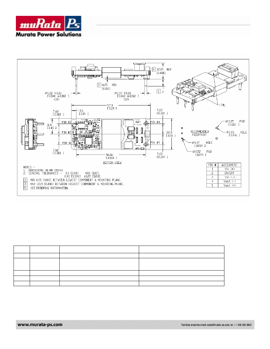
Mechanical Information
Figure 1
Pin Assignment
Table 4
Pin #
Pin Name
Function
Notes & Conditions
1
Vi(+)
Positive Input Voltage
2
En
Input Enable / Disable
Referenced to Vi(-).
Positive Logic: Floating = Enabled
Negative Logic: Floating = Disabled
3
Vi(-)
Negative Input Voltage
4 Vo(-)
Negative
Output
Voltage
5
Vo(+)
Positive Output Voltage
BUS CONVERTER
EUS15-120 Model
4
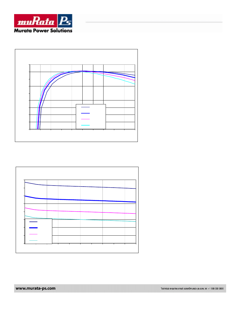
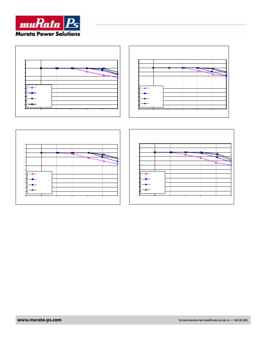
Efficiency Curves
Figure 2
Output Voltage vs. Current
Figure 3
Vo (V) vs. Io (A) and Vin (V)
6
7
8
9
10
11
12
13
14
0
2
4
6
8
10
12
14
16
18
20
55 Vin
48 Vin
42 Vin
38 Vin
Efficiency (%) vs. Iout (A) and Vin (V)
88%
89%
90%
91%
92%
93%
94%
95%
96%
97%
0
2
4
6
8
10
12
14
16
18
20
55Vin
48Vin
42Vin
38Vin
BUS CONVERTER
EUS15-120 Model
5
Thermal Derating Curves (Transverse) T
TML
=120C
Airflow from pin 3 to pin 1
Figure 7
Iout (A) vs. Tamb (C) and Air Flow (LFM)
38 Vin
0
2
4
6
8
10
12
14
16
18
20
22
24
25
35
45
55
65
75
85
100 LFM
200 LFM
300 LFM
400 LFM
Iout (A) vs. Tam b (C) and Air Flow (LFM)
42 Vin
0
2
4
6
8
10
12
14
16
18
20
22
24
25
35
45
55
65
75
85
100 LFM
200 LFM
300 LFM
400 LFM
Iout (A) vs. Tam b (C) and Air Flow (LFM)
55 Vin
0
2
4
6
8
10
12
14
16
18
20
22
24
25
35
45
55
65
75
85
100 LFM
200 LFM
300 LFM
400 LFM
Iout (A) vs. Tam b (C) and Air Flow (LFM)
48 Vin
0
2
4
6
8
10
12
14
16
18
20
22
24
25
35
45
55
65
75
85
100 LFM
200 LFM
300 LFM
400 LFM
Figure 4
Figure 5
Figure 6
BUS CONVERTER
EUS15-120 Model
6
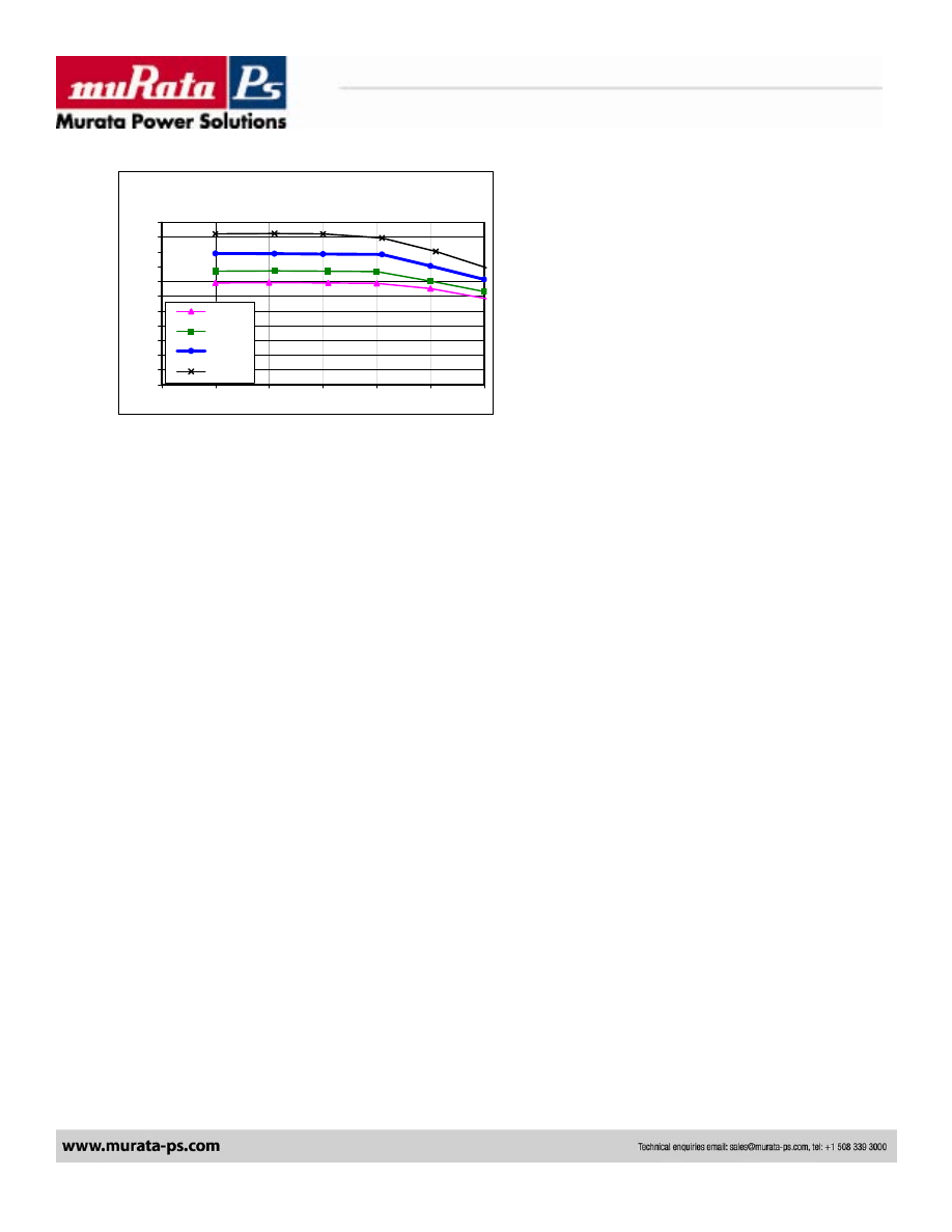
Figure 8
Pout (W) vs. Tamb (C) and Vin (V)
200 LFM
0
25
50
75
100
125
150
175
200
225
250
275
25
35
45
55
65
75
85
38 Vin
42 Vin
48 Vin
55 Vin
BUS CONVERTER
EUS15-120 Model
7
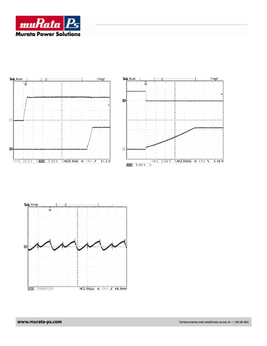
Turn-on from Vin (Enable On)
Turn-on from Enable (Vin present)
Figure 9
Ch3: En; Ch2: Vout
Figure 10
Ch3: Vin; Ch2: Vout
Vin=48V,
Io=15A,
Co=3000uF
Vin=48V,
Io=15A,
Co=3000uF
Output Ripple/Noise
Figure 11 Vin=48V,
Io=15A
Vripple = 114 mVpp
BUS CONVERTER
EUS15-120 Model
Safety Considerations
Figure 12
Ordering Information
The EUS series of converters are certified to the standards listed in the ‘Standards Compliance’ section in the table above. If this product is built into information
technology equipment, the installation must comply with the above standard.
An external input fuse (10 A recommended), must be used to meet the above requirements.
The output of the converter [Vo(+)/Vo(-)] is considered to remain within SELV limits when the input to the converter meets SELV or TNV-2 requirements.
The converters and materials meet UL 94V-0 flammability ratings.
BUS CONVERTER
EUS15-120 Model
Wyszukiwarka
Podobne podstrony:
więcej podobnych podstron