
E N G I N E
Return To Main Table of Contents
ENGINE MOUNTING . . . . . . . . . . . . . . . . . . . . . . . . . . . . . . . . . . 19
ENGINE AND TRANSAXLE ASSEMBLY . . . . . . . . . . . . . . . 2 3
TIMING BELT . . . . . . . . . . . . . . . . . . . . . . . . . . . . . . . . . . . . . . . . . 2 7
ROCKER ARMS AND ROCKER ARM SHAFTS . . . . . . . 3 3
CAMSHAFT . . . . . . . . . . . . . . . . . . . . . . . . . . . . . . . . . . . . . . . . . . . 3 6
CYLINDER HEAD . . . . . . . . . . . . . . . . . . . . . . . . . . . . . . . . . . . . . 40
VALVES AND VALVE SPRINGS . . . . . . . . . . . . . . . . . . . . . . . 44
JET VALVE . . . . . . . . . . . . . . . . . . . . . . . . . . . . . . . . . . . . . . . . . . . . 50
FRONT CASE, OIL PUMP . . . . . . . . . . . . . . . . . . . . . . . . . . . . .
PISTON AND CONNECTING ROD . . . . . . . . . . . . . . . . . . . . 59
CRANKSHAFT . . . . . . . . . . . . . . . . . . . . . . . . . . . . . . . . . . . . . . . . . 64
FLYWHEEL . . . . . . . . . . . . . . . . . . . . . . . . . . . . . . . . . . . . . . . . . . . . 67
CYLINDER BLOCK . . . . . . . . . . . . . . . . . . . . . . . . . . . . . . . . . . . . 68
OIL PRESSURE SWITCH . . . . . . . . . . . . . . . . . . . . . . . . . . . . . .

GENERAL
GENERAL
SPECIFICATIONS
Description
Standard
Limit
General
Type
In-line OHC
Number of cylinders
4
Bore
75.5 mm (2.97 in.)
Stroke
82 mm (3.23 in.)
Total displacement
1,468 cc (89.6 cu.in.)
Compression ratio
9.4
Firing order
1 - 3 - 4 - 2
Basic ignition timing
Refer to emission control
information label on car
Valve timing
Intake valve
Opens (BTDC)
18.5°
Closes (ABDC)
51.5°
Exhaust valve
[MPI]
[FBC]
Opens (BBDC)
51.5°
47.50
Closes (ATDC)
18.5°
14.50
Compression pressure
1.32 MPa (13.5 kg/cm
2
,
192 psi)/250 rpm
Valve clearance-Hot engine
Intake valve
0.15 mm (0.006 in.)
Exhaust valve
0.25 mm (0.010 in.)
*Jet valve
0.25 mm (0.010 in.)
Cylinder head
Warpage of lower face of head
Within 0.05 mm (0.002 in.)
Clearance with camshaft
0.05-0.09 mm (0.002-0.0035 in.)
Oversize rework dimension of valve seat hole
Intake
0.3 mm (0.102 in.)
0.6 mm (0.024 in.)
Exhaust
0.3 mm (0.012 in.)
0.6 mm (0.024 in.)
Oversize rework of valve guide hole
(both intake and exhaust)
0.05 mm (0.002 in.)
0.25 mm (0.010 in.)
0.50 mm (0.020 in.)
Camshaft
Height of cam lobe
Intake
Exhaust
3 9 . 3 - 3 9 . 3 2 5 mm (1.5472-1.5482 in.)
3 9 . 6 - 3 9 . 6 2 5 mm (1.5590-1.5600 in.)
3 4 . 3 - 3 4 . 3 2 5 mm (1.3504-1.3514 in.)
3 4 . 6 - 3 4 . 6 2 5 mm (1.3622-1.3632 in.)
0.1 mm (0.004 in.)
End play
13.05-13.068 mm (0.5135-0.5145 in.)
13.25-13.268 mm (0.5216-0.5224 in.)
13.50-13.518 mm (0.5315-0.5323 in.)
38.909 mm (1.5318 in.)
-0.5 mm (-0.020 in.)
38.974 mm (1.5344 in.) [MPI]
-0.5 mm (-0.020 in.)
38.648 mm (1.5216 in.) [FBC]
-0.5 mm (-0.020 in.)
0.05-0.20 mm (0.002-0.008 in.)
0.4 mm (0.016 in.)
* : FBC only
2 0 - 2

GENERAL
Description
Standard
Limit
Valve
Stem O.D.
Intake
Exhaust
Thickness of valve head (Margin)
Intake
Exhaust
Clearance with valve guide
Intake
Exhaust
Valve guide
Installed dimension
Oversize
Valve seat insert
Width of seat contact
Seat angle
Oversize
Valve spring
Free length
Load
Installed height
Squareness
*Jet valve
Stem O.D.
Seat angle
*Jet valve spring
Free length
Load
Cylinder block
Cylinder bore
6.6 mm (0.26 in.)
6.6 mm (0.26 in.)
1.0 mm (0.039 in.)
0.7 mm (0.028 in.)
1.5 mm (0.059 in.)
1.0 mm (0.039 in.)
0.03-0.06 mm (0.0012-0.0024 in.)
0.10 mm (0.004 in.)
0.05-0.09 mm (0.0020-0.0035 in.)
0.15 mm (0.006 in.)
13.7-14.3 mm (0.5394-0.5630 in.)
0.05 mm, 0.25 mm, 0.50 mm
(0.002 in., 0.010 in., 0.020 in.)
0.9-1.3 mm (0.035-0.051 in.)
4 5 °
0.3 mm, 0.6 mm (0.012 in., 0.024 in.)
44.6 mm (1.756 in.)
24 kg/27.3 mm (53 lb./1.075 in.)
36 mm (1.417 in.)
1.5° or less
4.3 mm (0.1693 in.)
45°
-1.0 mm (-0.039 in.)
+1 mm (+0.039 in.)
3 °
29.60 mm (1.1654 in.)
3.5 kg/21.5 mm (5.5 lb/0.846 in.)
75.50-75.53 mm (2.9724-2.9736 in.)
Out-of-roundness and taper of cylinder bore Within 0.02 mm (0.0008 in.)
Clearance with piston
0.02-0.04 mm (0.0008-0.0016 in.)
Piston
O.D.
Oversize
75.47-75.5 mm (2.9713-2.9724 in.)
.25 mm, 0.50 mm, 0.75 mm, 1.00 mm
(0.010 in., 0.020 in., 0.030 in., 0.039 in.)
Piston ring
Side clearance
No.1
0.03-0.07 mm (0.0012-0.0028 in.)
0.15 mm (0.006 in.)
No.2
0.02-0.06 mm (0.0008-0.0024 in.)
0.12 mm (0.005 in.)
End gap
No. 1 and No .2
0.20-0.35 mm (0.008-0.0138 in.)
0.8 mm (0.031 in.)
Oil ring
0.20-0.70 mm (0.008-0.028 in.)
1.0 mm (0.039 in.)
Oversize
0.25 mm, 0.50 mm, 0.75 mm, 1.00 mm
(0.010 in., 0.020 in., 0.030 in., 0.039 in.)
* : FBC only
2 0 - 3

GENERAL
Description
Standard
Limit
Connecting rod
Bend
Twist
Side clearance
Connecting rod bearing
Oil clearance
Undersize
Crankshaft
Pin O.D.
Journal O.D.
Bend
Out-of-roundness, taper of journal and pin
End play
Undersize rework dimension of pin
0.25 mm (0.010 in.)
0.50 mm (0.020 in.)
0.75 mm (0.030 in.)
Undersize rework dimension of journal
0.25 mm (0.010 in.)
0.50 mm (0.020 in.)
0.75 mm (0.030 in.)
Flywheel
Out-of-roundness
Engine oil pressure
At engine idle speed
Oil pump
Outer gear
Clearance between outer circumference
and front case
Clearance between addendum and crescent
End play
Inner gear
Clearance between addendum and crescent
End play
Relief spring
Free height
Load
0.05 mm (0.0020 in.) or less
0.10 mm (0.0039 in.) or less
0.10-0.25 mm (0.004-0.010 in.)
0.4 mm (0.016 in.)
0.014-0.044 mm (0.0006-0.0017 in.)
0.25 mm, 0.50 mm, 0.75 mm
(0.01 in., 0.02 in., 0.03 in.)
42 mm (1.6535 in.)
48 mm (1.8898 in.)
Within 0.03 mm (0.0012 in.)
Within 0.01 mm (0.0004 in.)
0.05-0.18 mm (0.002-0.007 in.)
0.25 mm (0.0098 in.)
41.73541.750 mm (1.6431-1.6437 in.)
41.48541.500 mm (1.6333-1.6339 in.)
41.235-41.250 mm (1.6234-1.6240 in.)
47.73547.750 mm (1.8793-1.8799 in.)
47.48547.500 mm (1.8695-1.8701 in.)
47.23547.250 mm (1.8596-1.8602 in.)
Within 0.13 mm
(0.005 in.)
78 kPa (0.8 kg/cm
2
, 11 psi) or more
[Engine oil temperature 75-90°C (167-190°F)]
0.1-0.2 mm (0.0039-0.0079 in.)
0.22-0.34 mm (0.0087-0.0134 in.)
0.04-0.10 mm (0.0016-0.0039 in.)
0.21-0.32 mm (0.0083-0.0126 in.)
0.04-0.10 mm (0.0016-0.0039 in.)
46.6 mm (1.835 in.)
6.1 kg/40.1 mm (13.4 lb/1.579 in.)
2 0 - 4

GENERAL
TIGHTENING TORQUE
Nm
kg.cm
lb.ft
Cylinder Block
Front engine support bracket bolt
Front roll stopper bracket bolt
Rear roll stopper bracket bolt
Left engine support bracket bolt
Oil pressure switch
Cylinder head
Cylinder head bolt-cold engine
-hot engine
Intake/exhaust manifold bolts or nuts
Rocker cover bolt
Rocker arm shaft bolt
Camshaft bolt
Rear plate bolt
*Jet valve
Main Moving
Connecting rod cap nut
Crankshaft bearing cap
Flywheel (manual transaxle) bolt
Drive plate (automatic transaxle) bolt
Timing Belt
Crankshaft pulley bolt
Crankshaft sprocket bolt
Camshaft sprocket bolt
Timing belt tensioner bolt
Timing belt cover bolt
Front case bolt
4 9 - 6 9
5 0 0 - 7 0 0
3 7 - 5 0
5 4 - 7 4
5 5 0 - 7 5 0
4 0 - 5 4
1 0 8 - 1 2 7
1 1 0 0 - 1 3 0 0
8 0 - 9 4
2 9 - 4 1
3 0 0 - 4 2 0
2 2 - 3 0
1 5 - 2 1
1 5 0 - 2 2 0
1 1 - 1 5
6 9 - 7 4
7 0 0 - 7 5 0
5 1 - 5 4
7 8 - 8 3
8 0 0 - 8 5 0
5 8 - 6 1
1 5 - 2 0
1 5 0 - 2 0 0
1 1 - 1 4
1 . 5 - 2 . 0
1 5 - 2 0
1 . 1 - 1 . 4
2 0 - 2 6
2 0 0 - 2 7 0
1 4 - 2 0
2 0 - 2 6
2 0 0 - 2 7 0
1 4 - 2 0
8 - 1 0
8 0 - 1 0 0
5 . 8 - 7 . 2
1 8 - 2 2
1 8 0 - 2 2 0
1 3 - 1 6
3 1 - 3 4
3 2 0 - 3 5 0
2 3 - 2 5
4 9 - 5 3
5 0 0 - 5 4 0
3 6 - 3 9
1 2 7 - 1 3 7
1 3 0 0 - 1 4 0 0
9 4 - 1 0 1
1 2 7 - 1 3 7
1 3 0 0 - 1 4 0 0
9 4 - 1 0 1
1 2 - 1 5
1 2 0 - 1 5 0
8 . 7 - 1 1
6 9 - 9 8
7 0 0 - 1 0 0 0
5 1 - 7 2
6 4 - 7 4
6 5 0 - 7 5 0
4 7 - 5 4
2 0 - 2 6
2 0 0 - 2 7 0
1 4 - 2 0
1 0 - 1 2
1 0 0 - 1 2 0
7 . 2 - 8 . 7
1 2 - 1 5
1 2 0 - 1 5 0
8 . 7 - 1 1
* : FBC only
2 0 - 5

GENERAL
Nm
kg.cm
lb.ft
Engine Mounting
Left mounting insulator (large) nut
Left mounting insulator (small) nut
Left mounting bracket to engine nuts and bolts
Transaxle mount insulator nut
Transaxle insulator bracket to side member bolts
Transaxle mount bracket to automatic transaxle nut
Rear roll stopper insulator nut
Rear roll stopper bracket to center member bolts
Front roll stopper insulator nut
Front roll stopper bracket to center member bolts
Center member to body bolts
Roll rod to engine bolt
Roll rod to roll rod bracket nut
Roll rod bracket to body bolts
Oil filter
Oil pan bolts
Oil pan drain plug
Oil screen bolts
Timing belt upper cover bolts
Timing belt lower cover bolts
Surge tank to inlet manifold nuts and bolts
8 8 - 1 0 8
9 0 0 - 1 1 0 0
6 5 - 8 0
4 9 - 5 9
5 0 0 - 6 0 0
3 6 - 4 3
4 9 - 6 4
5 0 0 - 6 5 0
3 6 - 4 7
8 8 - 1 0 8
9 0 0 - 1 1 0 0
6 5 - 8 0
2 9 - 3 9
3 0 0 - 4 0 0
2 2 - 2 9
8 8 - 1 0 8
9 0 0 - 1 1 0 0
6 5 - 8 0
4 4 - 5 9
4 5 0 - 6 0 0
3 3 - 4 3
4 4 - 5 9
4 5 0 - 6 0 0
3 3 - 4 3
4 4 - 5 9
4 5 0 - 6 0 0
3 3 - 4 3
2 9 - 3 9
3 0 0 - 4 0 0
2 2 - 2 9
5 9 - 7 8
6 0 0 - 8 0 0
4 3 - 5 8
5 4 - 6 4
5 5 0 - 6 5 0
4 0 - 4 7
4 4 - 5 9
4 5 0 - 6 0 0
3 3 - 4 3
6 9 - 9 3
7 0 0 - 9 5 0
5 1 - 6 5
1 1 - 1 3
1 1 0 - 1 3 0
8 - 9 . 4
6 - 8
6 0 - 8 0
4 - 6
3 4 - 4 4
3 5 0 - 4 5 0
2 5 - 3 3
1 5 - 2 2
1 5 0 - 2 2 0
1 1 - 1 6
1 0 - 1 2
1 0 0 - 1 2 0
7 - 9
1 0 - 1 2
1 0 0 - 1 2 0
7 - 9
1 5 - 2 0
1 5 0 - 2 0 0
1 1 - 1 4
2 0 - 6
SELECTION OF LUBRICANTS
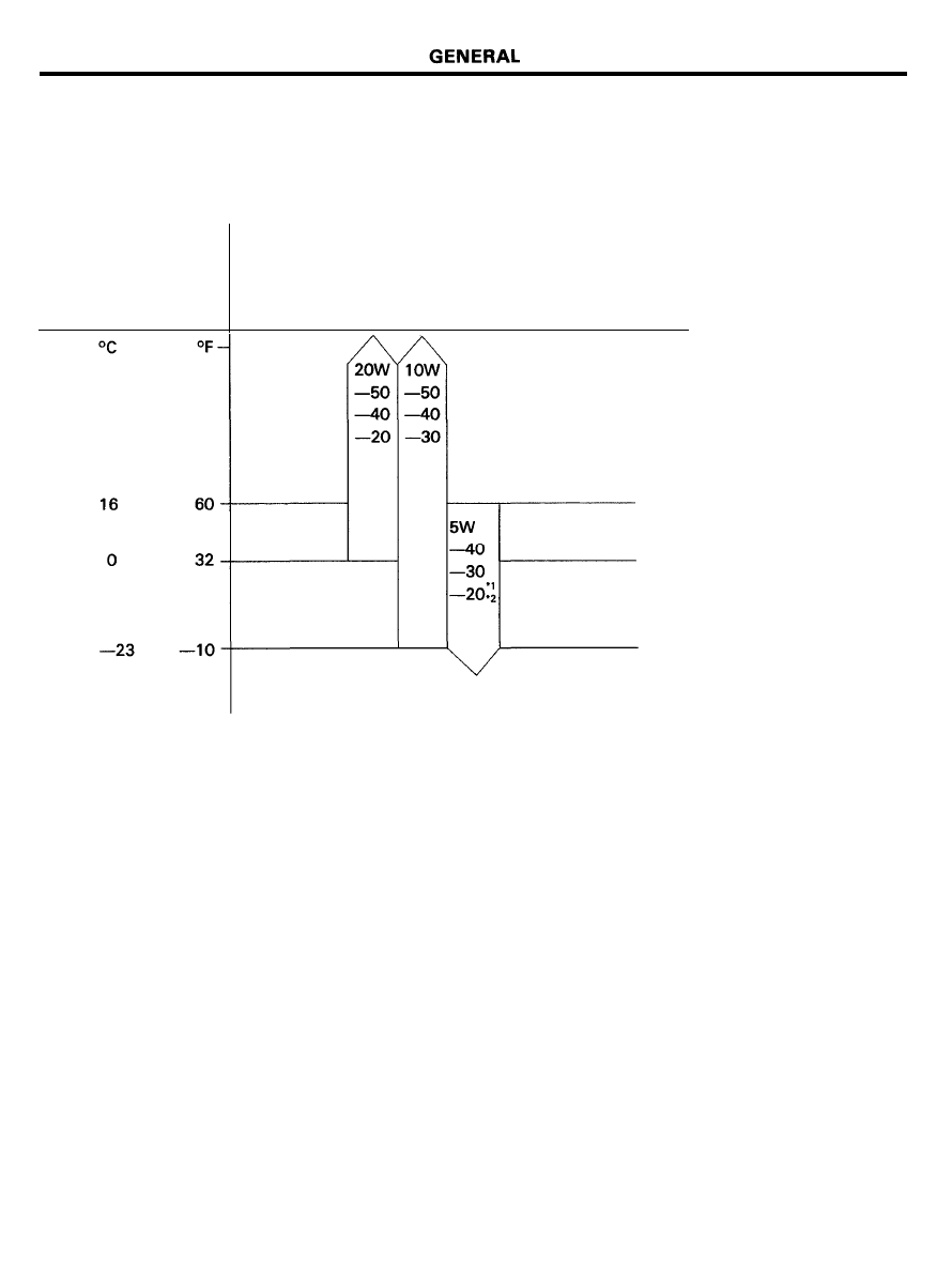
Engine Oil
Recommended API classification : SF, SF/CC OR SG
Recommended SAE viscosity grades :
Temperature range
anticipated before
next oil change
Recommended SAE viscosity number
*1. Restricted by driving conditions and climate conditions.
*2. Not recommended for sustained high speed vehicle operation.
For best performance and for maximum protection of all engines for all types of operation, select only those lubricants
which:
1. Conform to the requirements of API classification.
2. Have proper SAE grade number for expected ambient temperature range.
Lubricants which do not have both a SAE grade number and an API service classification on the container should
not be used.
2 0 - 7
GENERAL
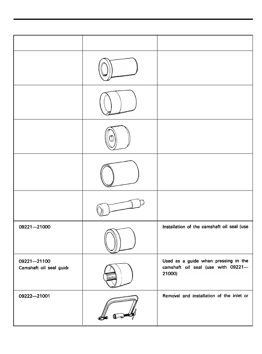
SPECIAL TOOLS
Tool
(Number and name)
0 9 2 1 4 - 2 1 0 0 0
Crankshaft front oil seal
installer
Illustration
Use
Installation of the crankshaft front oil seal
(use with 09214-21100)
0 9 2 1 4 - 2 1 1 0 0
Crankshaft front oil seal
guide
Installation of the crank shaft front oil
seal (use with 09214-21000)
0 9 2 1 6 - 2 1 0 0 0
Mount bushing remover and
installer arbor
Removal and installation of the front roll
rod upper bushing (use with 09216-
21100 and 09216-21000)
0 9 2 1 6 - 2 1 1 0 0
Mount bushing remover and
installer base
Removal and installation of the roll rod
upper bushing (use with 09216-21000)
0 9 2 2 1 - 1 1 0 0 1
Cylinder head bolt wrench
Removal and tightening of the cylinder
head bolt
Camshaft oil seal installer
with 09221-21100)
Valve spring compressor
exhaust valve
2 0 - 8
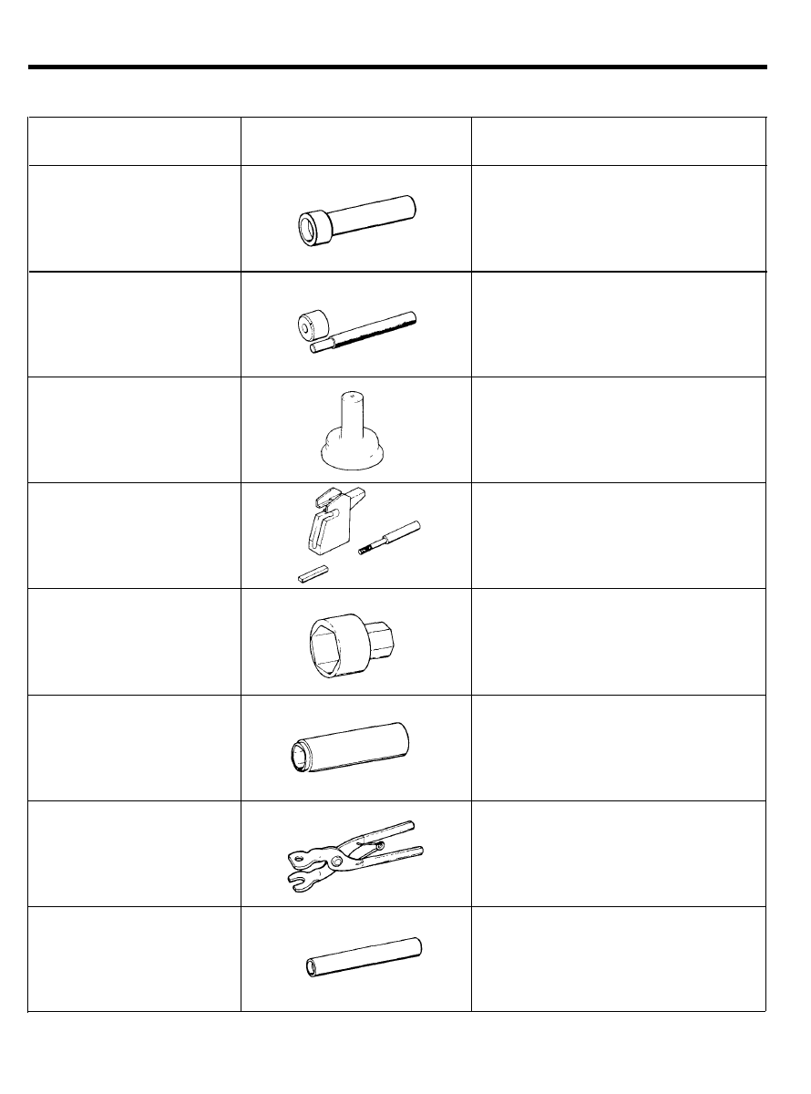
GENERAL
Tool
(Number and name)
0 9 2 2 2 - 2 1 1 0 0
Valve stem oil seal installer
0 9 2 2 2 - 2 1 2 0 0
Valve guide installer
Illustration
Use
Installation of the valve stem oil seal
Removal and installation of the valve
guide
0 9 2 3 1 - 2 1 0 0 0
Crankshaft rear oil seal
installer
1. Installation of the engine rear oil seal
2. Installation of the crankshaft rear oil
seal
0 9 2 3 4 - 2 1 0 0 0
Piston pin setting tool
0 9 2 6 0 - 1 1 0 0 0
Oil pressure switch wrench
Removal and installation of the piston pin
Removal and installation of the oil
pressure switch
0 9 2 2 2 - 2 1 3 0 0
*Jet valve socket wrench
0 9 2 2 2 - 2 1 4 0 0
*Jet valve spring plier
Removal and installation of jet valve
For assembling and reassembling jet
valve
0 9 2 2 2 - 2 1 5 0 0
Installation of the jet valve stem oil seal
*Jet valve stem seal installer
* : FBC only
2 0 - 9

GENERAL
TROUBLESHOOTING
Symptom
Low compression
Probable cause
Blown cylinder head gasket
Worn or damaged piston rings
Worn piston or cylinder
Worn or damaged valve seat
Remedy
Replace gasket
Replace rings
Repair or replace piston
and/or cylinder block
Repair or replace valve
and/or seat ring
Oil pressure drop
Low engine oil level
Check engine oil level
Faulty oil pressure switch
Replace
Clogged oil filter
Replace
Worn oil pump gears or cover
Replace
Thin or diluted engine oil
Change and determine cause
Oil relief valve stuck (open)
Repair
Excessive bearing clearance
Replace
High oil pressure
Oil relief valve stuck (closed)
Repair
Excessive engine rolling and
Loose engine roll stopper (front, rear)
Re-tighten
vibration
Loose transaxle mount bracket
Re-tighten
Loose engine mount bracket
Re-tighten
Loose center member
Re-tighten
Broken transaxle mount insulator
Replace
Broken engine mount insulator
Replace
Broken engine roll stopper insulator
Replace
Noisy valves
Thin or diluted engine oil (low oil pressure)
Change
Worn or damaged valve stem or valve guide
Replace
Connecting rod and/main
lnsufficient oil supply
Check engine oil level
bearing noise
Thin or diluted engine oil
Change and determine cause
Excessive bearing clearance
Replace
Timing belt noise
Incorrect belt tension
Adjust belt tension
2 0 - 1 0
GENERAL
CHECKING ENGINE OIL
1. Position the vehicle on a level surface.
2. Warm up the engine.
NOTE
If a vehicle that has been out of service for a prolonged
period of time, warm up the engine for approximately 20
minutes.
3. Stop the engine, and wait 2 or 3 minutes, then check the
oil level after engine oil drains to the oil pan.
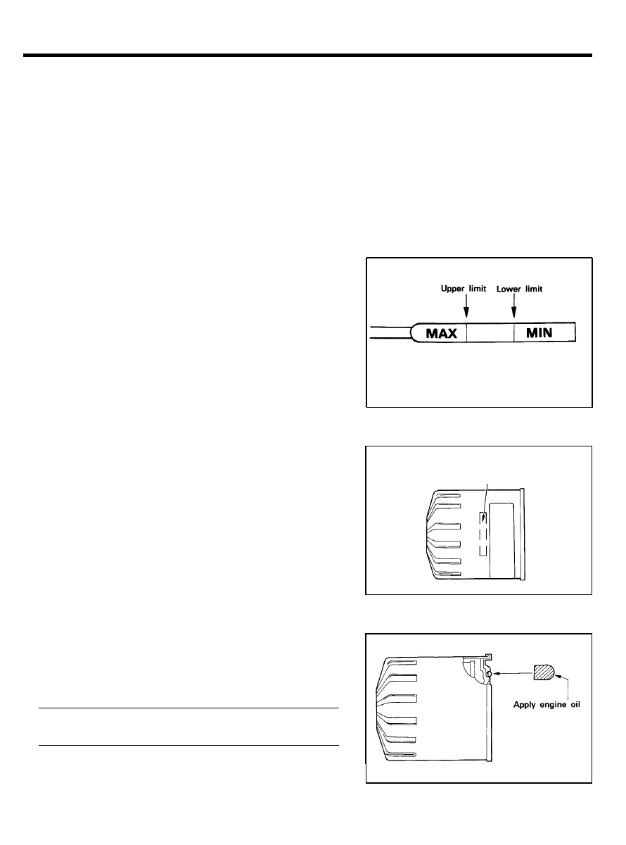
4. Check that the engine oil level is within the level range
indicated on the oil dipstick. If the oil level is found to have
fallen to the lower limit (the MIN mark), refill to the “MAX”
mark.
NOTE
When refilling, use the same type of engine oil as the one
currently being used.
5.
Check that the oil is not dirty or contaminated with coolant
or gasoline, and that it has the proper viscosity.
REPLACING OIL FILTER
Filter Selection
All Hyundai engines are equipped with a high quality,
throw-away oil filter. This filter is recommended as a
replacement filter on all vehicles. The quality of replacement
filters varies considerably. Only high quality filters should be
used to assure the most efficient service. Make sure that the
rubber gasket from the old oil filter is completely removed from
the mating surface on the engine block, before installing the new
filter.
Replacing Oil Filter
1. Use a filter wrench to remove the oil filter.
2.
Before installing the new oil filter on the engine, apply clean
engine oil to the surface of the rubber gasket.
3. Tighten the oil filter to the specified torque.
Tightening torque
Oil filter . . . . 11-13 Nm (110-130 kg.cm, 8-9.4 lb.ft)
4. Run the engine to check for engine oil leaks.
5.
After stopping the engine, check the oil level and add oil as
necessary.
Part number
2 0 - 1 1
GENERAL
CHANGING ENGINE OIL
1. Run the engine until it reaches normal operating temper-
ature.
2. Stop the engine.
3.
Remove the oil filler cap (on rocker cover) and the drain plug
(on the oil pan). Drain the engine oil.
4.
Re-install and tighten the drain plug to the specified torque.
Tightening torque
Drain plug . . 34-44 Nm (350-450 kg.cm, 25-33 Ib.ft)
5.
Fill the crankcase with fresh engine oil through the oil filler
cap opening.
Dry fill . . . . . . . . . . . . . . 3.4 lit (3.59 U.S.qts., 2.99 Imp.qts.)
Drain and Refill
Without oil filter; 2.6 lit (2.74 U.S.qts., 2.28 Imp.qts.)
With oil filter; 3.0 lit (3.17 U.S.qts., 2.64 Imp.qts.)
6. Install the oil filler cap.
7. Start and run the engine.
8. Stop the engine and then check the oil level. Add oil if
necessary.
TIGHTENING CYLINDER HEAD BOLTS
1. When retorquing cylinder head bolts, slightly loosen and
then tighten to the specified torque.
2. Be sure to follow the specified torquing sequence.
3. After the cylinder head bolts have been tightened to the
specified torque, run the engine until normal operating
temperature is reached. Allow it to cool down, then re-torque
the bolts to specification for best results.
Tightening torque
C o l d e n g i n e. . . . . . . . . . . . . . . . . . . . . . . . . . . . . . . . . . . . . . . . . .
69-73 Nm (704-745 kg.cm, 51-54 lb.ft)
H o t e n g i n e. . . . . . . . . . . . . . . . . . . . . . . . . . . . . . . . . . . . . . . . . . .
79-83 Nm (806-847 kg.cm, 58-61 lb.ft)
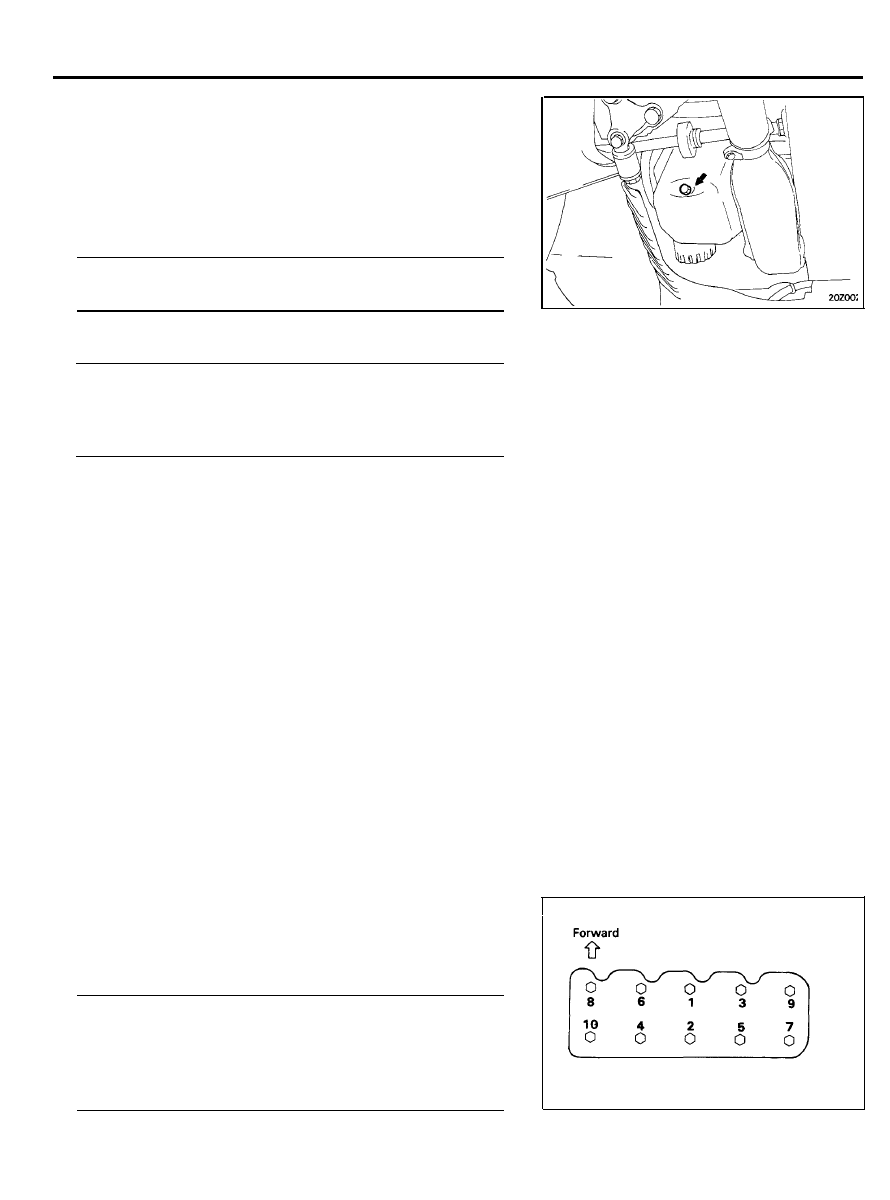
Cylinder head bolt tightening sequence
2 0 - 1 2
GENERAL
CHECKING COMPRESSION PRESSURE
1. Before checking compression, check the engine oil level.
Make sure the starter motor and battery are in normal
operating condition.
2.
Start the engine and wait until engine coolant temperature
reaches 80-95°C (176-205°F).
3. Stop the engine and disconnect the spark plug cables.
4. Remove the spark plugs.
5. Crank the engine to remove any foreign objects in the
cylinders.
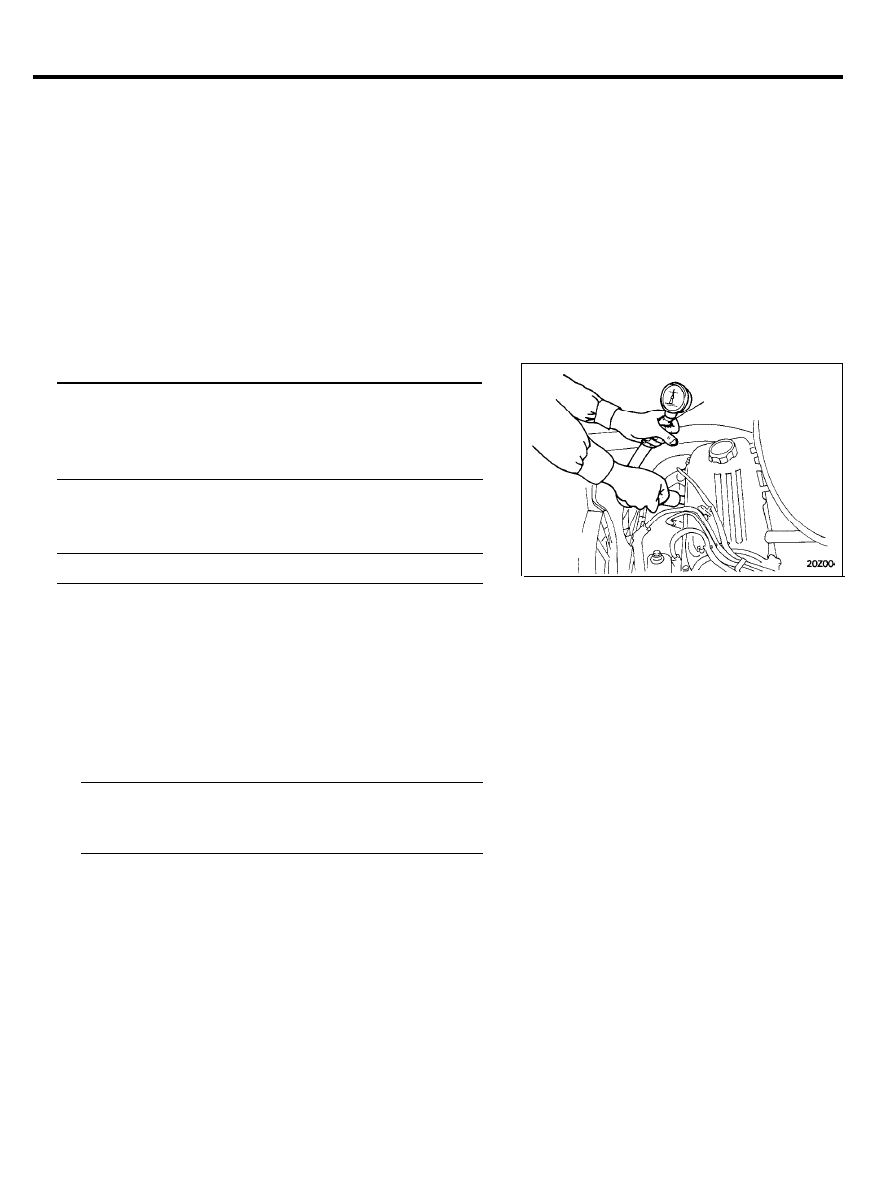
6. Attach the compression gauge to the spark plug hole.
7. Depress the accelerator pedal to fully open the throttle.
8. Crank the engine and read the gauge.
Standard value : 13.5 kg/cm
2
(1.32 MPa, 192 psi)
[250-400 rpm]
Limit : 12.0 kg/cm* (1.18 MPa, 171 psi)
[250-400 rpm]
9.
Repeat steps 6 through 8 on all cylinders, making sure that
the pressure differential for each of the cylinders is within
the specified limit.
Limit : Max. 1.0 kg/cm2 (100 kPa, 14 psi) between cylinders
10. If a cylinder’s compression or pressure differential is below
the specification, add a small amount of oil through the spark
plug hole and repeat steps 6 through 9.
1) If the addition of oil brings the compression up, it is
possible that there is wear between the piston ring and
cylinder wall.
2) If compression remains the same, valve seizure, poor
valve seating or a compression leak from the cylinder
head gasket are all possible causes.
Tightening torque
Spark plug . . . . . . . . . . . . . . . . . . . . . . . . . . . . . . . . . . . . . . .
20-30 Nm (204-306 kg.cm, 15-21 lb.ft)
VALVE CLEARANCE ADJUSTMENT
Refer to GROUP 10 Lubrication and Maintenance.
Compression gauge
2 0 - 1 3
GENERAL
TIMING BELT AND TIMING BELT
TENSIONER INSTALLATION PROCEDURE
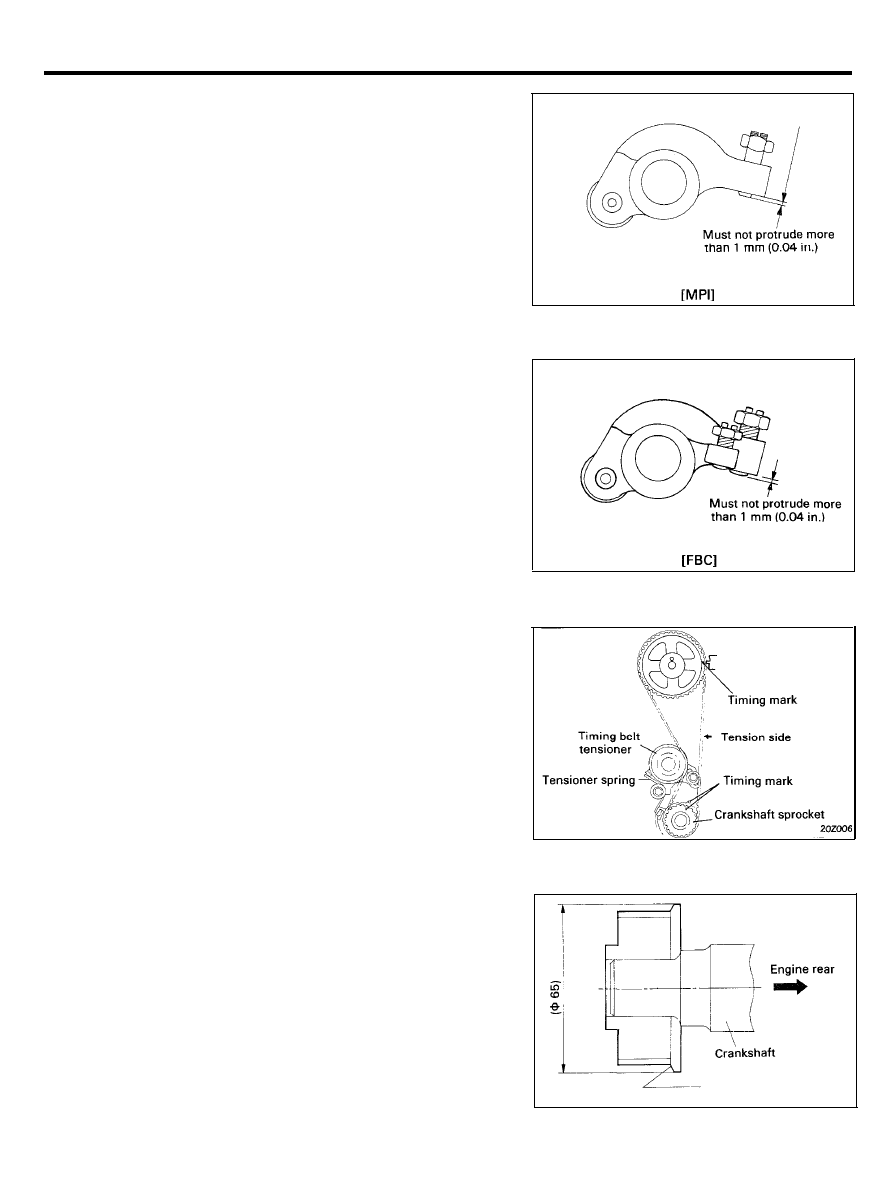
1. Assemble rocker arm adjusting screw in tentative state.
Then screw must not protrude more than 1 mm (0.04 in.)
NOTE
1) Take special care not screw to be below arm end,
otherwise valve stem would rust thread part.
2) In case of protruding too much, tension of belt would
be excessive.
2. Tentatively fasten timing belt tensioner at such position as
to place it’s pulley nearest to water pump (pulley may touch
water pump body).
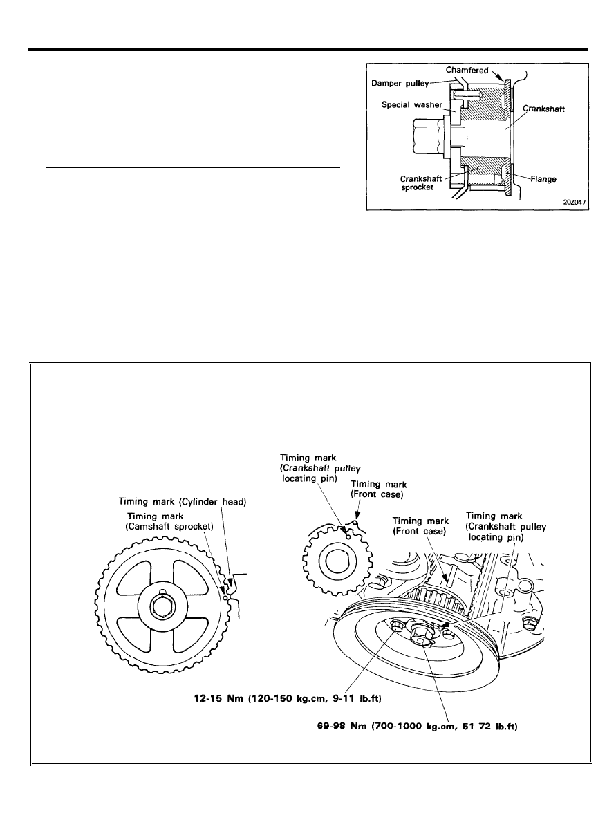
3. After installing the tensioner, the crankshaft sprocket and
the camshaft sprocket, match timing mark of each sprocket
as shown in illustration.
Rotate the crankshaft until the piston in No.1 cylinder is at
top dead center on the compression stroke.
CAUTION
1) Be sure to install the flange in the correct direction.
(Chamfered part shows front of engine).
2) When installing the camshaft sprocket, make sure that
the pin on the camshaft fits small hole in pulley.
Chamfered
2 0 - 1 4
GENERAL
NOTE
Allow tensioner to remain in assemble state must be
installed temporarily as follows.
1) Tentatively tighten tensioner at position as shown in
illustration, in state that one extended end of spring
tensioner is assembled to bend of tensioner bracket as
imaginary line (wheel spring tensioner is inoperative
and not loaded).
2) Then set extended end of tensioner spring at front case
with drive etc.
4.
Install the timing belt so as not to allow slack to the tension
side. Make sure that all timing marks are at their correct
position with the tension side in a strained state by applying
force to the camshaft sprocket in a reversing (counter-
clockwise) direction.
TIMING BELT TENSION ADJUSTMENT
PROCEDURE
The timing belt has an automatic tension adjusting mechanism.
Adjustment can be made by the following procedure:
1. Turn the steering wheel fully counter-clockwise.
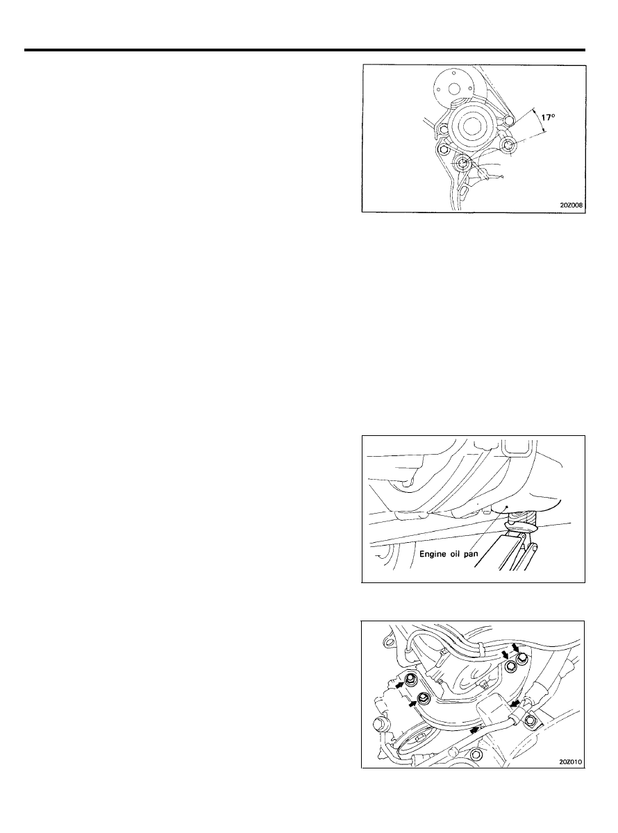
2. Apply a wood block under the engine oil pan and carefully
raise the engine.
CAUTION
Jack up only slightly to prevent undue stress on parts.
3. Remove the engine left mount bracket.
2 0 - 1 5
GENERAL
4. Remove the water pump pulley.
5. Remove the timing belt upper cover.
6.
Check the belt for cracking, peeling or other damage. Be sure
to carefully check the entire length of the belt.
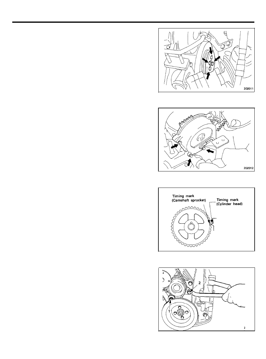
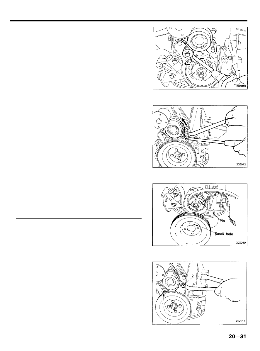
7.
Rotate the crankshaft so that the No. 1 piston is at top dead
center of the compression stroke. In other words, align the
timing mark on the camshaft sprocket with that on the
cylinder head.
Note that the crankshaft should be turned clockwise, not
counterclockwise. Turning the crankshaft counterclockwise
will cause the tension to become improperly adjusted.
8. Remove the timing belt lower cover.
9. Loosen the tensioner mounting bolts 1 and 2 in that order
as shown to give the timing belt spring tension.
2 0 - 1 6
GENERAL
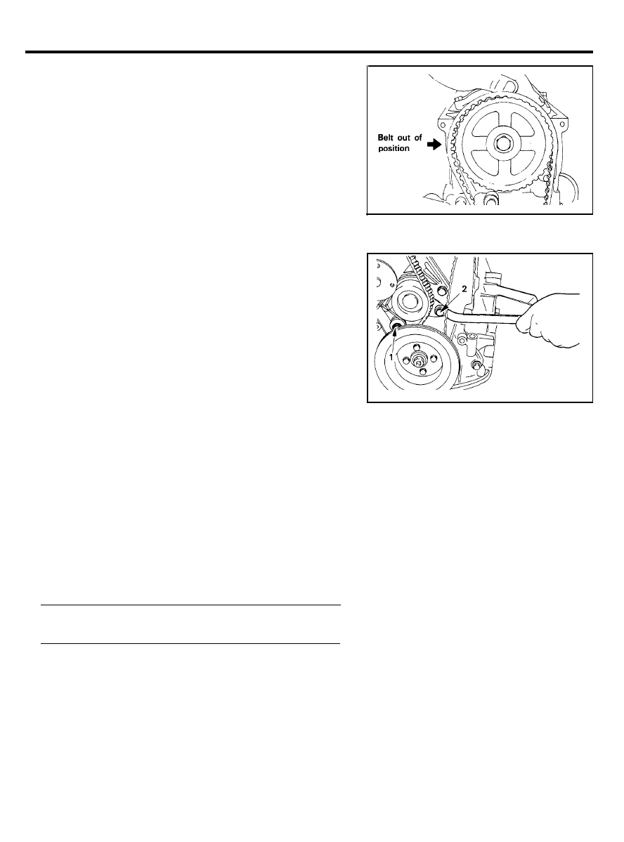
10. Check the belt to ensure that it is not out of position.
11. Tighten the tensioner attaching bolts 2 and 1 in that order
as shown. If the bolt 1 is tightened first, the tensioner will
move with the bolt and cause the belt to become
overtightened.
12. Give the crankshaft one turn in operating direction
(clockwise) and realign crankshaft sprocket timing mark with
the top dead center position.
CAUTION:
Do not turn the crankshaft in a counterclockwise
direction.
13. Loosen the tensioner attaching bolts 1 and 2 in that order
as shown.
14. Retighten the tensioner attaching bolts 2 and 1 in that order
as shown to the specified torque.
Tightening torque . . . . . . . . . . . . . . . . . . . . . . . . . . . . . . . . . . . . . . .
20-26 Nm (200-270 kg.cm, 14-20 lb.ft)
2 0 - 1 7
GENERAL
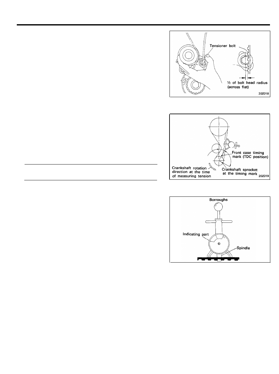
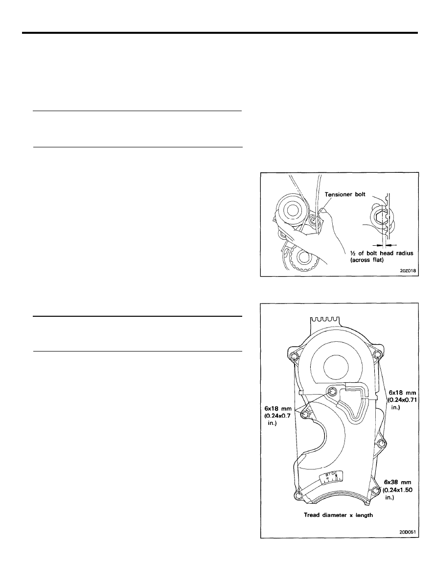
15. Recheck the belt tension, When the tensioner and the
tension side of the timing belt are pushed in horizontally with
a moderate force [approx. 49 N (11 lb)], the timing belt cog
end is approx. ½ of the tensioner mounting bolt head radius
(across flats) away from the bolt head center.
TENSION MEASURING PROCEDURE
(When using a tension gauge)
1. Rotate the crankshaft counterclockwise to position 90
degrees before top dead center as shown in the illustration.
2.
Measure the belt tension in the middle of the tension side
span using the tension gauge. (BORROUGHS BT-33-73F
TYPE)
Timing belt tension (In cool condition). . . . . . . . . . . . . . . . .
14.5-21.5 kg (32-47 lb)
CAUTION
Place the arms on the bottom of the belt teeth. Place the
spindle against the middle of the back surface of the belt.
2 0 - 1 8
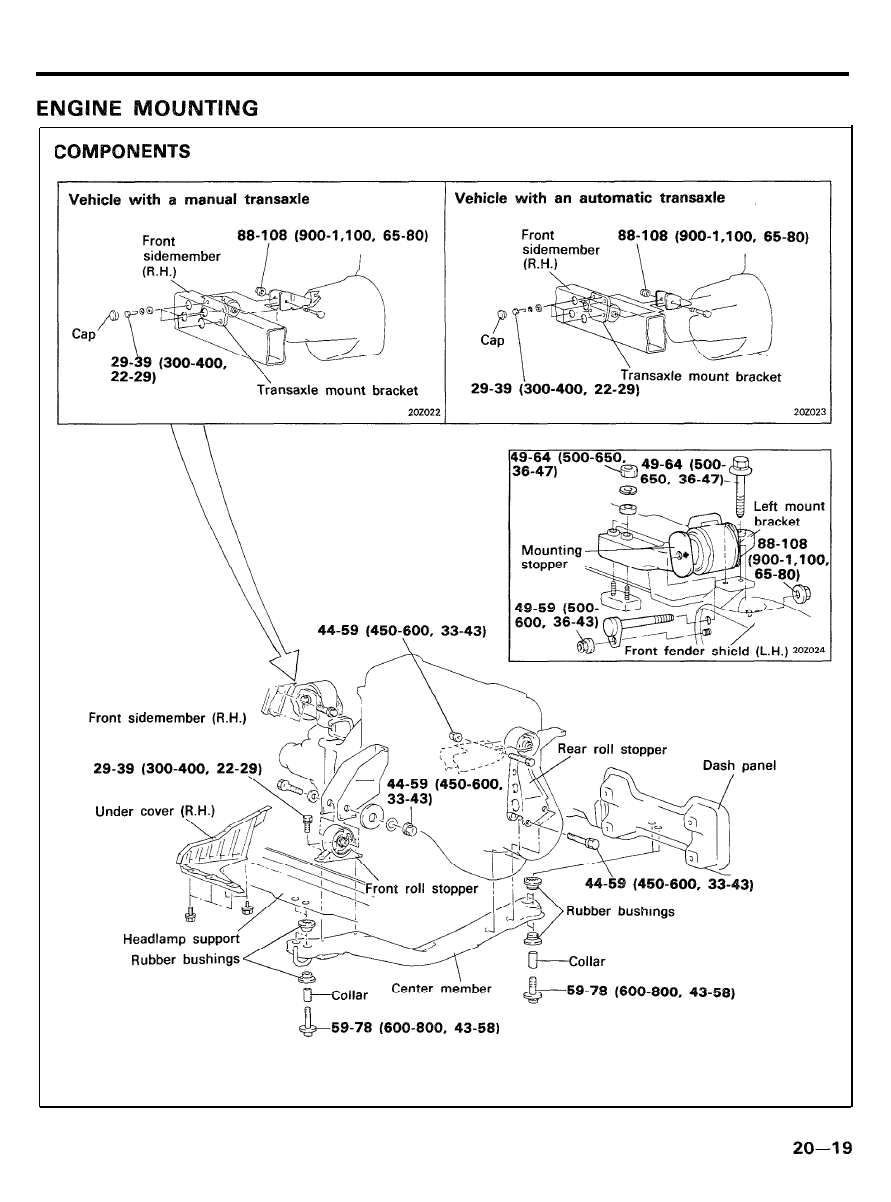
ENGINE MOUNTING
TORQUE
: Mm (kg.cm, lb.ft)
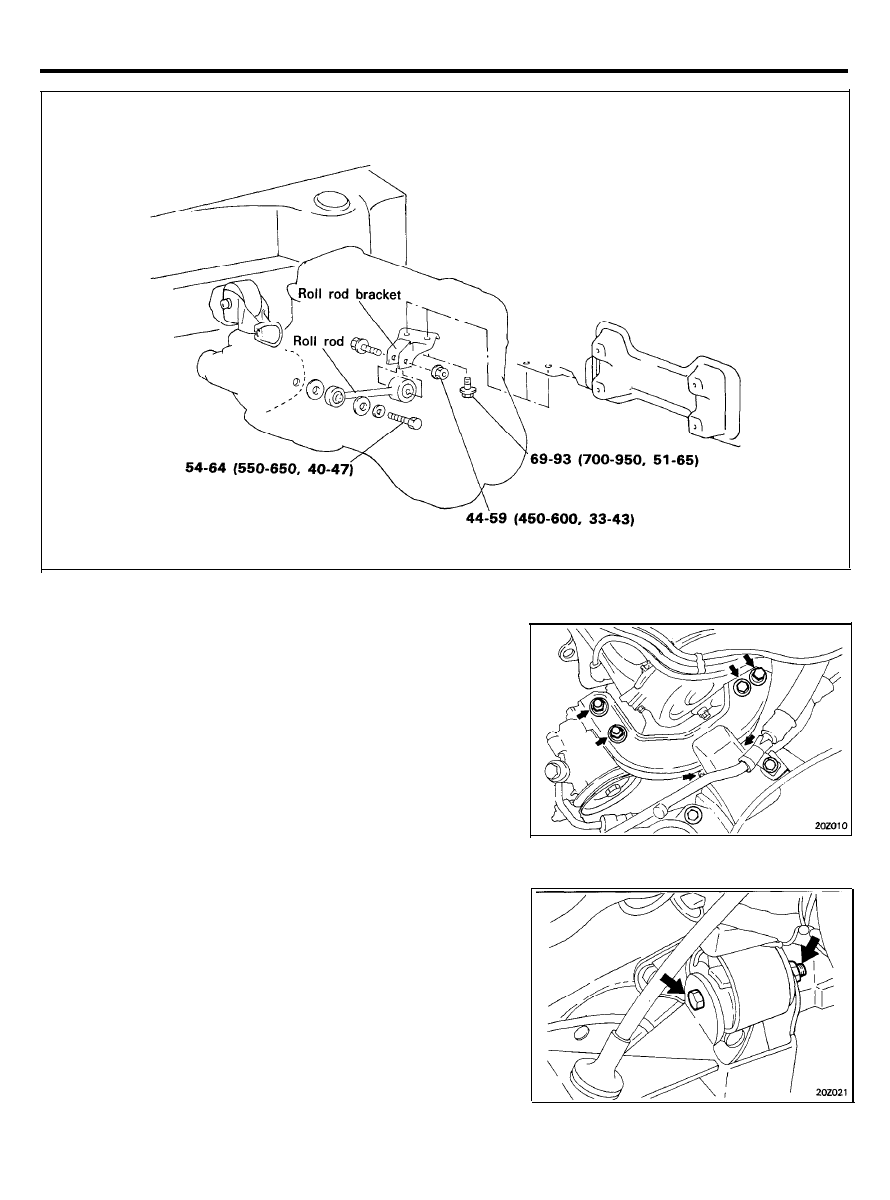
ENGINE MOUNTING
Roll rod (Vehicle with a manual transaxle)
TORQUE : Nm (kg.cm, lb.ft)
REMOVAL
Attach an engine hoist to the engine hooks, and raise it just enough
so that there is no pressure on the insulators.
Engine Mounting
1. Remove the engine mount insulator bolts.
2. Remove the engine mount bracket from the engine.
Transaxle
1. For vehicles with a 5-speed manual transaxle, remove the
select control valve.
2. Remove the transaxle mount bolt.
2 0 - 2 0
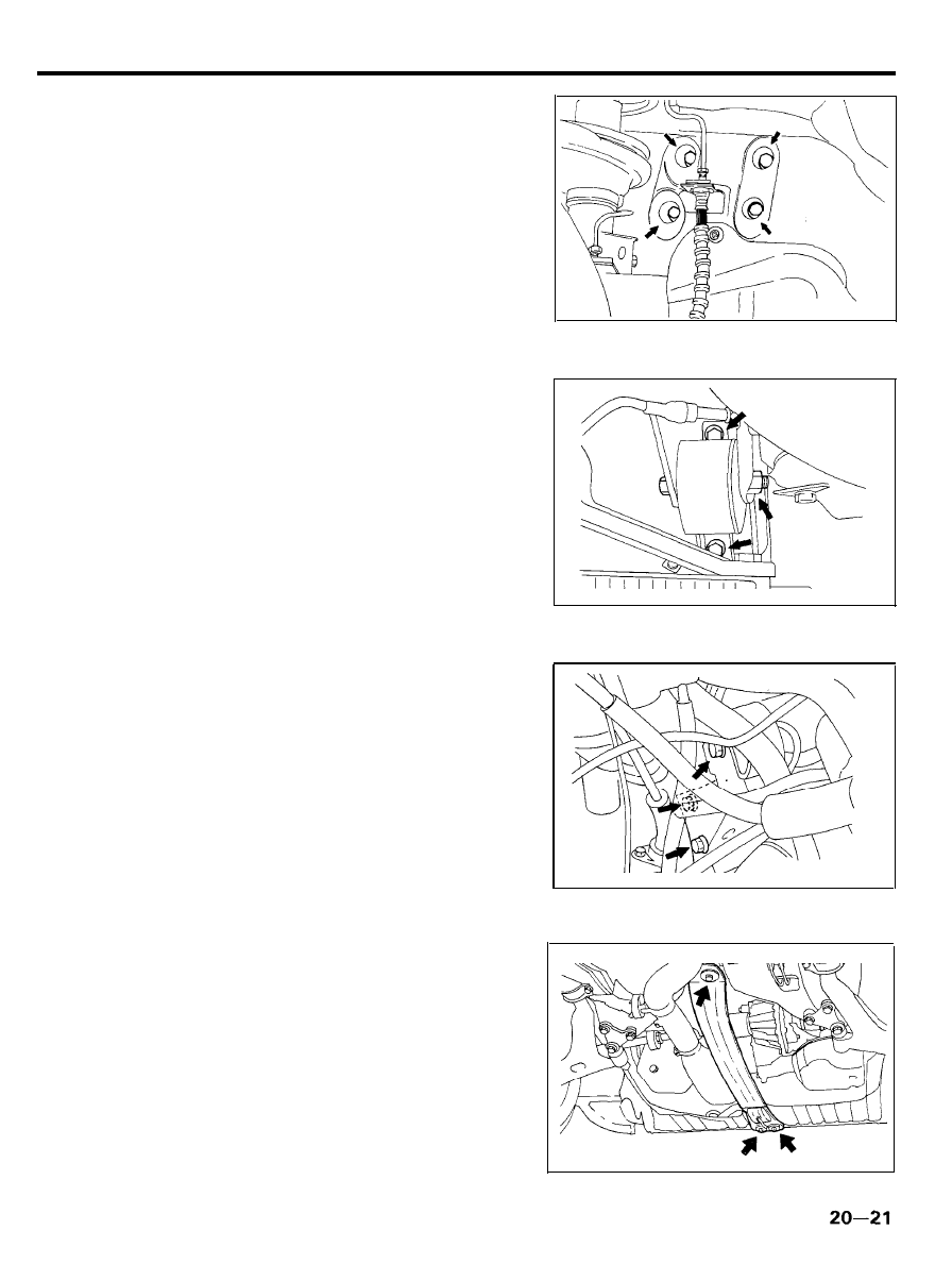
ENGINE MOUNTING
3. Detach the cap from the inside of the right fender shield,
remove the transaxle mounting bolts.
4. Remove the transaxle bracket.
Front Roll Stopper
Remove the front roll stopper bracket from the center member.
Rear Roll Stopper
Remove the rear roll stopper from the center member.
Center member
1. Remove the under cover (R.H.).
2. Remove the front roll stopper mounting bolts.
3. Remove the rear roll stopper mounting bolts.
4. Remove the center member from the body.

ENGINE MOUNTING
Roll Rod (Manual Transaxle only)
Before removal, place a piece of tape as illustrated to the bottom
side of the roll rod for identification.
INSPECTION ITEMS
Transaxle mounting
Engine mounting
Front roll stopper
Rear roll stopper
Cracks, peeling
and damage
Cracks, peeling,
and damage
Center member
Cracks and damage
Roll rod (Manual Transaxle only)
Cracks, peeling
and damage
2 0 - 2 2
ENGINE AND TRANSAXLE ASSEMBLY
ENGINE AND TRANSAXLE ASSEMBLY
REMOVAL
1. Remove the battery.
2. Detach the air cleaner.
3.
Disconnect the connectors for the backup lamp and engine
harness.
4. For a vehicle with a 5-speed manual transaxle, disconnect
the select control valve connector.
5.
Disconnect the connectors for the alternator harness and the
oil pressure gauge wiring.
6. Drain the engine coolant.
7. For vehicles with an automatic transaxle, disconnect the
transaxle oil cooler hoses.
NOTE
When disconnecting the hoses, identify their location to
avoid making any errors during reassembly.
CAUTION
Be careful not to spill any oil or fluid from any of the
openings. Also take care in preventing the entrance of
foreign material.
8.
Disconnect the radiator upper and lower hoses on the engine
side, and then remove the radiator assembly.
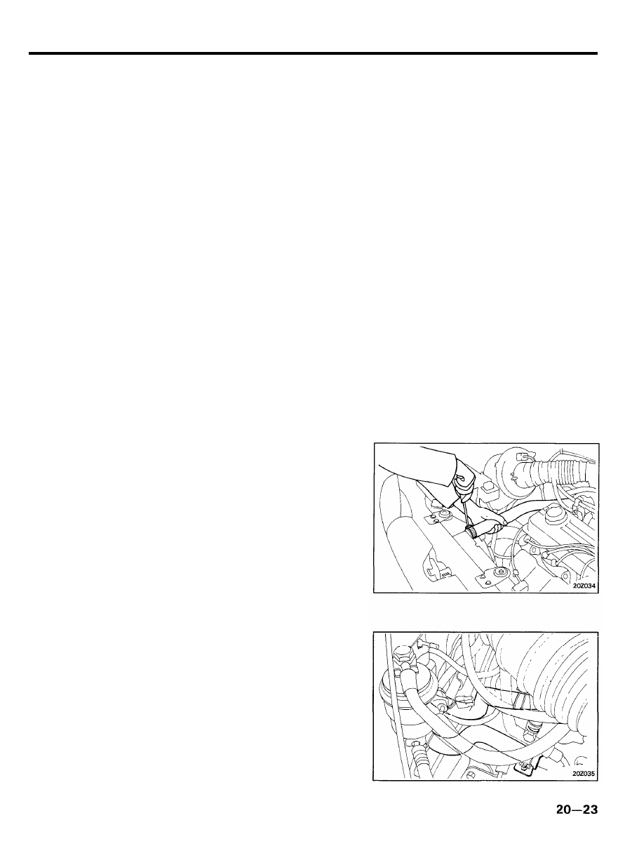
9 . Disconnect the high tension cable and all wires to the
distributor from the ignition coil section.
10. Disconnect the engine ground.
11. Disconnect the brake booster vacuum hose.
12. Remove the main fuel line, and the return and vapor hoses
from the engine side.
CAUTION
To reduce the residual pressure in the hoses, refer to
Group Fuel System “Fuel filter replacement” [For MPI
System].
13. Disconnect the heater hoses (inlet and outlet) on the engine
side.
14. Disconnect the accelerator cable at the engine side.
15. For vehicles with a manual transaxle, remove the clutch
cable from the transaxle.
16. For vehicles with an automatic transaxle, remove the control
cable from the transaxle.
ENGINE AND TRANSAXLE ASSEMBLY
17. Disconnect the speedometer cable from the transaxle.
18. Disconnect the air conditioner from the mounting bracket.
19. Jack up the vehicle.
20. Drain the transaxle oil (or fluid).
21. Disconnect the front exhaust pipe from the manifold.
NOTE:
Use wire to suspend the exhaust pipe from the bottom of
the vehicle.
22. For vehicles with a manual transaxle, remove the shift
control rod and extension rod.
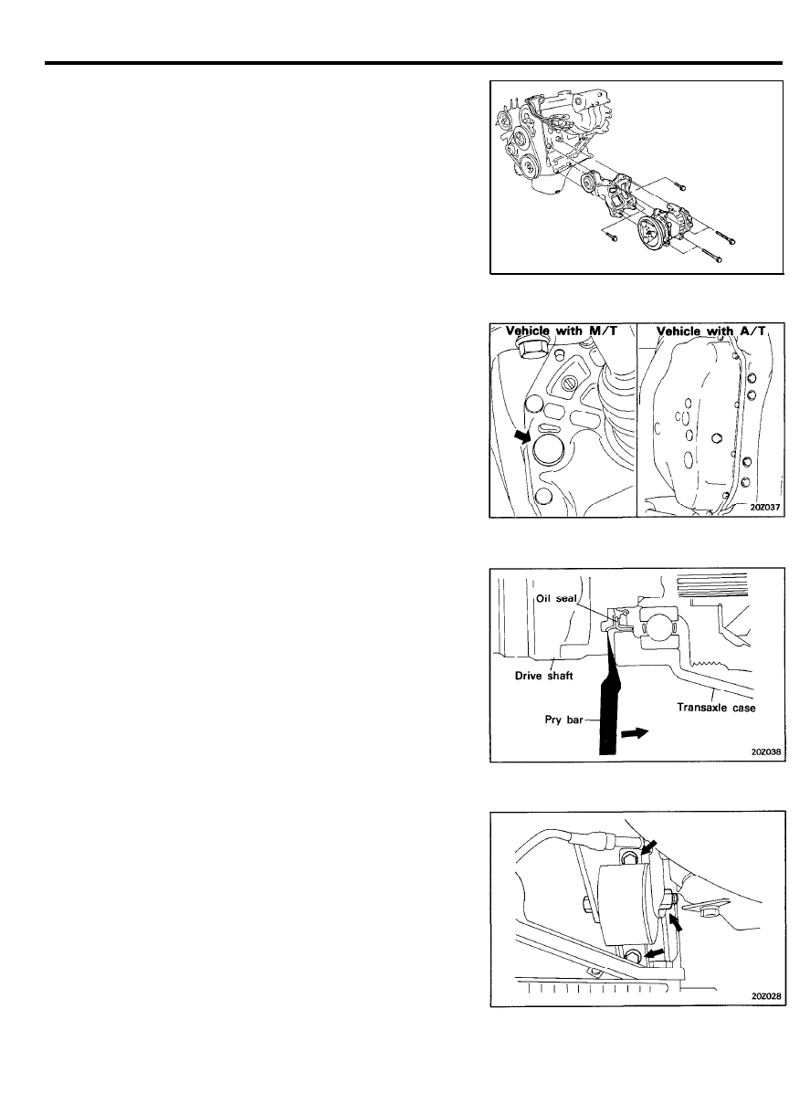
23. Remove the lower arm ball joint bolts and the strut bar at
the point where it is mounted to the lower arm.
24. Remove the drive shafts from the transaxle case.
CAUTION
1) Plug the holes of the transaxle case to prevent entry
of foreign material.
2 ) I n s t a l l n e w c i r c l i p s o n t h e d r i v e s h a f t s w h e n
reassembling.
25. Hang the lower arm and drive shaft from the body with a
string.
26. Attach a cable to the engine, and use a chain hoist to lift
the engine only enough to pull the cable tight.
27. Remove the front roll stopper.
28. Separate the rear roll stopper.
29. For vehicles with a manual transaxle, remove the roll rod.
2 0 - 2 4
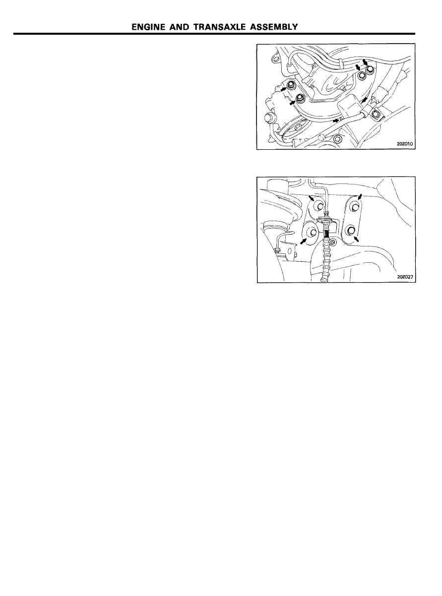
30. Remove the engine mounting insulator bolts.
31. Remove the engine mounting bracket from the engine.
32. Slowly raise the engine (to the extent that the engine and
transaxle weights are not applied to the mounting portions)
and temporarily hold it in the raised condition.
CAUTION
Check that all of the cables, hoses, harnesses, connectors
etc. are disconnected from the engine.
33. Remove the caps from inside the right fender shield and
remove the transaxle mount bracket bolts.
34. Remove the left mount insulator bolt.
While directing the transaxle side downward, lift the engine
and transaxle assembly up and out of the vehicles.
2 0 - 2 5
INSTALLATION
1. While checking the connections of the harnesses, pipes,
hoses, etc., and making sure that none of them are being
caught, damaged, etc., install the engine and transaxle
assembly.
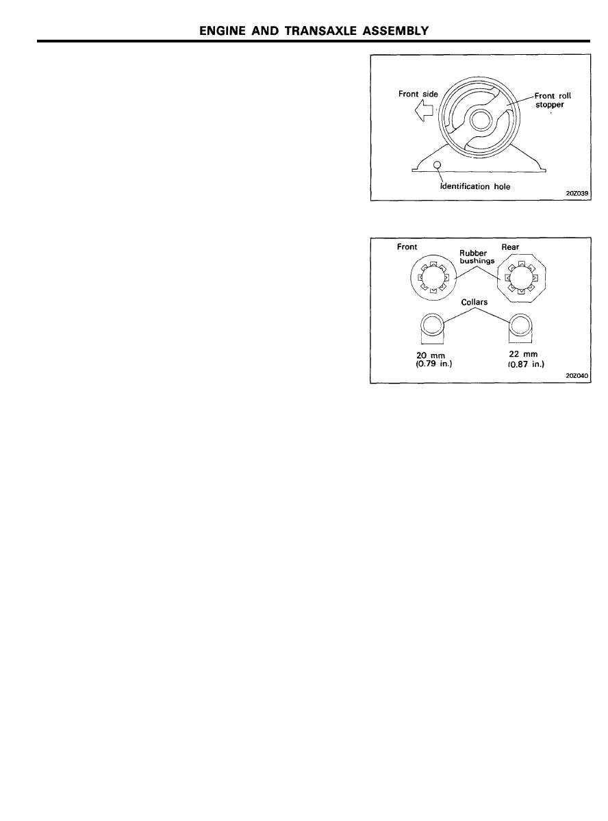
2. When the engine and transaxle assembly is installed
temporarily tighten the front roll stopper.
3. The front and rear center member rubber bushings and
collars are different.
4. After the weight of the engine and transaxle assembly has
been put on each insulator, tighten to specified torque.
5. Reassemble all of the components removed during disas-
sembly. Be especially careful to properly secure all
components,
including fuel,
electrical and fluid pipe
connections.
6. Refill the coolant and check for leaks.
7. Refill the transaxle fluid, test its operation, and check for
leaks.
8. Check the operation of the transaxle control cable and
accelerator cable. Adjust as necessary.
9. Check for proper operation of each of the various gauges.
2 0 - 2 6
TIMING BELT
TIMING BELT
COMPONENT
TORQUE : Nm (kg.cm, lb.ft)
REMOVAL
1. Remove the fan, spacer, water pump pulley, and belt.
2. Remove the timing belt cover.
3. Move the timing belt tensioner pulley toward the water
pump, and temporarily secure it.
4. Remove the timing belt from the camshaft sprocket.
5. Remove the camshaft sprocket.
6. Remove the crankshaft pulley.
7. Remove the timing belt.
NOTE
If the timing belt is reused, make an arrow mark indicating
the turning direction (or the front of the engine) to make
sure that the belt is reinstalled in the same direction as
before.
8. Remove the crankshaft sprocket bolts. Remove the crank-
shaft sprocket and flange.
9. Remove the timing belt tensioner.
2 0 - 2 7
TIMING BELT
INSPECTION
Sprockets and Tensioner
1. Check the camshaft sprocket, crankshaft sprocket and
tensioner for abnormal wear, cracks, or damage. Replace as
necessary.
2.
Inspect the tensioner for easy and smooth pulley rotation and
check for play or noise. Replace as necessary.
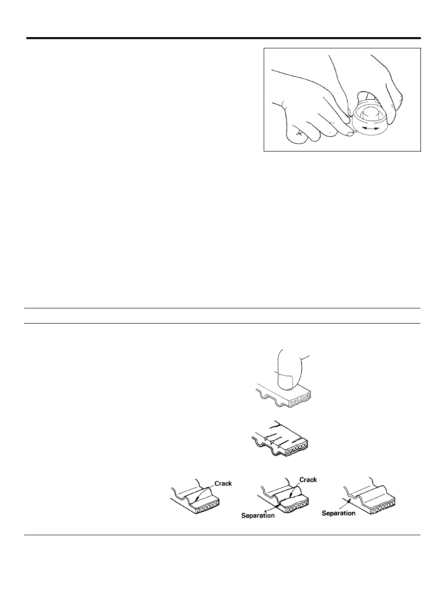
Timing Belt
1.
Check the belt for oil or dust deposits. Replace if necessary.
Small deposits should be wiped away with a dry cloth or
paper. Do not clean with solvent.
2. When the engine is overhauled or belt tension adjusted,
check the belt in detail. If the following flaws are evident,
replace the belt with a new one.
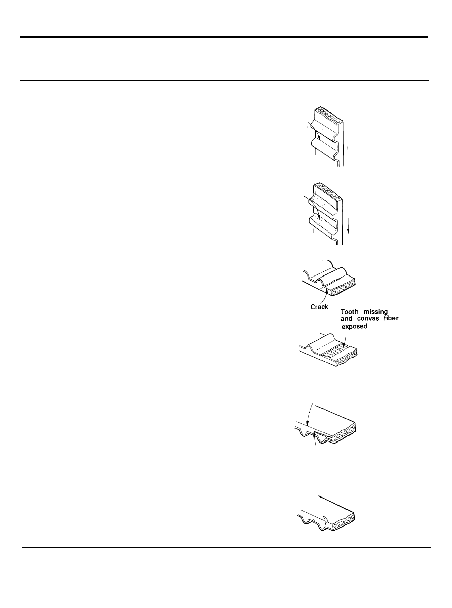
Description
1. Hardened back surface rubber
Flaw conditions
Back surface glossy. Non-elastic and so hard that even if a finger
nail is forced into it, no mark is produced.
2. Cracked back surface rubber
3. Cracked or separating canvas
2 0 - 2 8
TIMING BELT
Description
4. Badly worn teeth (initial stage)
Flaw conditions
Canvas on load side tooth flank worn
(Fluffy canvas fibers, rubber gone and color changed to white, and
5.
Badly worn teeth (last stage)
unclear canvas texture)
Flank worn
(On load side
Canvas on load side tooth flank worn down and rubber exposed
(tooth width reduced)
Rubber exposed
6. Cracked tooth bottom
7. Missing tooth
8. Side of belt badly worn
9. Side of belt cracked
Rounded belt side
NOTE
Abnormal wear (fluffy canvas fiber)
Normal belt should have precisely cut sides as if produced by
a sharp knife.
2 0 - 2 9
TIMING BELT
INSTALLATION
1. Install the flange and crankshaft sprocket as shown. Pay
close attention to their mounting directions.
Tightening torque
Crankshaft sprocket bolt . . . . . . . . . . . . . . . . . . . . . . . . . . . . . .
69-98 Nm (700-1,000 kg.cm, 51-72 lb.ft)
2. Install the camshaft sprocket and tighten the bolt to the
specified torque.
Tightening torque
Crankshaft sprocket bolt . . . . . . . . . . . . . . . . . . . . . . . . . . . . . .
64-74
Nm (650-750 kg.cm, 47-54 lb.ft)
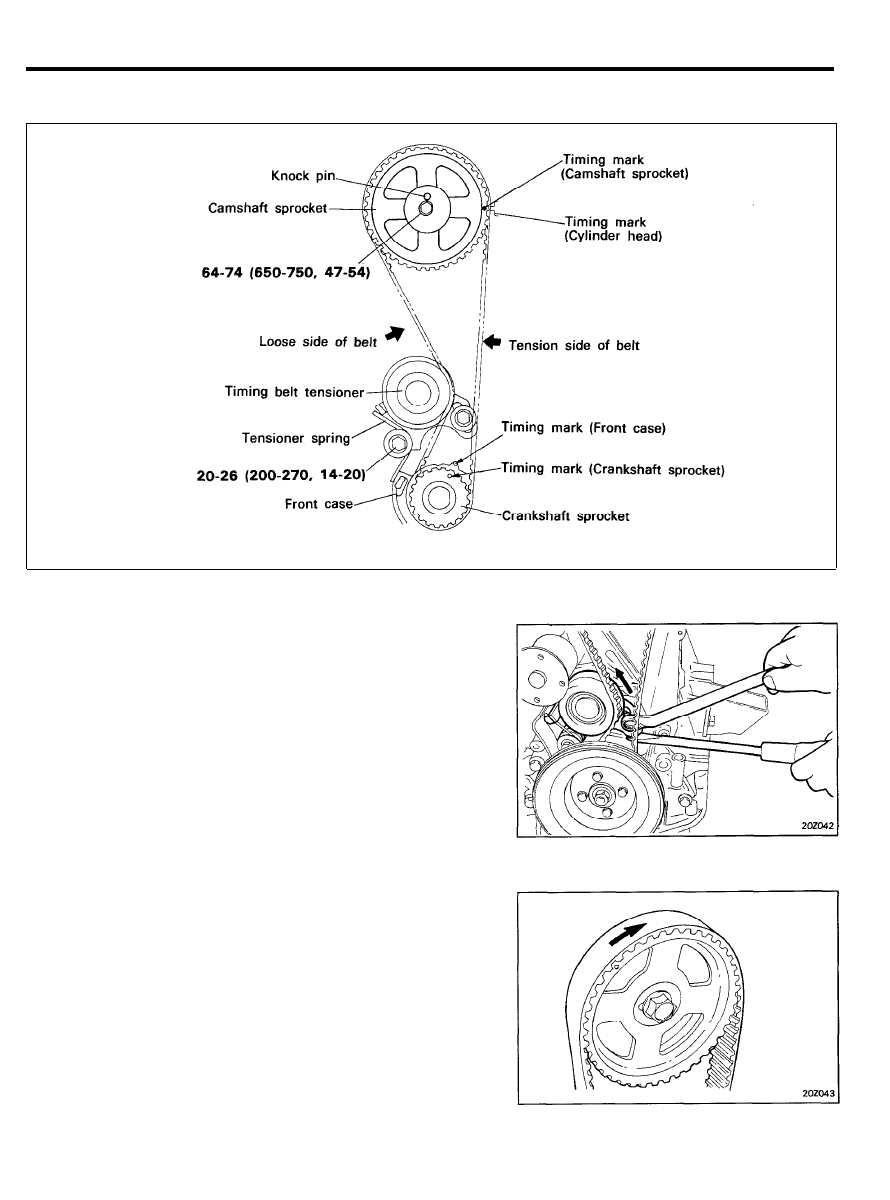
3. Align the timing marks of the camshaft sprocket and
crankshaft sprocket, with the No.1 piston placed at top dead
center on its compression stroke.
2 0 - 3 0
TIMING BELT
4.
To install the timing belt tensioner, first mount the tensioner,
spring, and spacer. Temporarily tighten the bolts. Next,
temporarily tighten the tensioner long hole side washer and
bolts. Install the bottom end of the spring against the front
case as shown in the illustration.
5. Secure the tensioner, positioned towards the water pump.
6. Install the timing belt on the crankshaft sprocket.
7. Install the timing belt on the camshaft sprocket.
When the timing belt is installed on the camshaft sprocket,
make sure that the tension side is tight. Then, check to
ensure that when the tension side is tightened by turning
the camshaft sprocket in a reverse direction, all timing marks
are in line.
8.
Install the crankshaft pulley. In this case, make sure that the
crankshaft sprocket pin fits the small hole in the pulley.
Tightening torque
Crankshaft pulley bolt . . . . . . . . . . . . . . . . . . . . . . . . . . . . . . . .
10-12 Nm (100-120 kg.cm, 7.2-8.7 lb.ft)
9. Loosen the tensioner mounting bolts 1 and 2 in that order
as shown. This will apply spring tension to the timing belt
only. Check the belt to ensure that it is not out of position.
10. Tighten the tensioner tightening bolts 1 and 2 in that order.
If the bolt 1 is tightened first, the tensioner will move with
the belt in the direction that the belt is tightened.
11. Rotate the crankshaft one revolution in a clockwise direction.
Realign the crankshaft sprocket timing mark with the top
dead center position.
TIMIMG BELT
CAUTION
Do not turn the crankshaft in a counterclockwise
direction. The crankshaft should turn smoothly.
12. Loosen the tensioner attaching bolts 1 and 2 in that order.
13. Tighten the tensioner attaching bolts 2 and 1 in that order
to the specified torque.
Tightening torque
Tensioner attaching bolt . . . . . . . . . . . . . . . . . . . . . . . . . . . .
20-26 Nm (200-270 kg.cm, 14-20 lb.ft)
14. Recheck the belt tension. Verify that when the tensioner and
the tension side of the timing belt are pushed in horizontally
with a moderate force [approx. 49 N (11 lb)], the timing belt
cog end is approx. ½ of the tensioner mounting bolt head
radius (across flats) away from the bolt head center.
15. Install the timing belt cover.
Tightening torque
Timing belt cover bolt . . . . . . . . . . . . . . . . . . . . . . . . . . . . . . . .
10-12 Nm (100-120 kg.cm, 7.2-8.7 lb.ft)
16. Install the fan belt and adjust the belt tension.
2 0 - 3 2
ROCKER ARMS AND ROCKER ARM SHAFTS
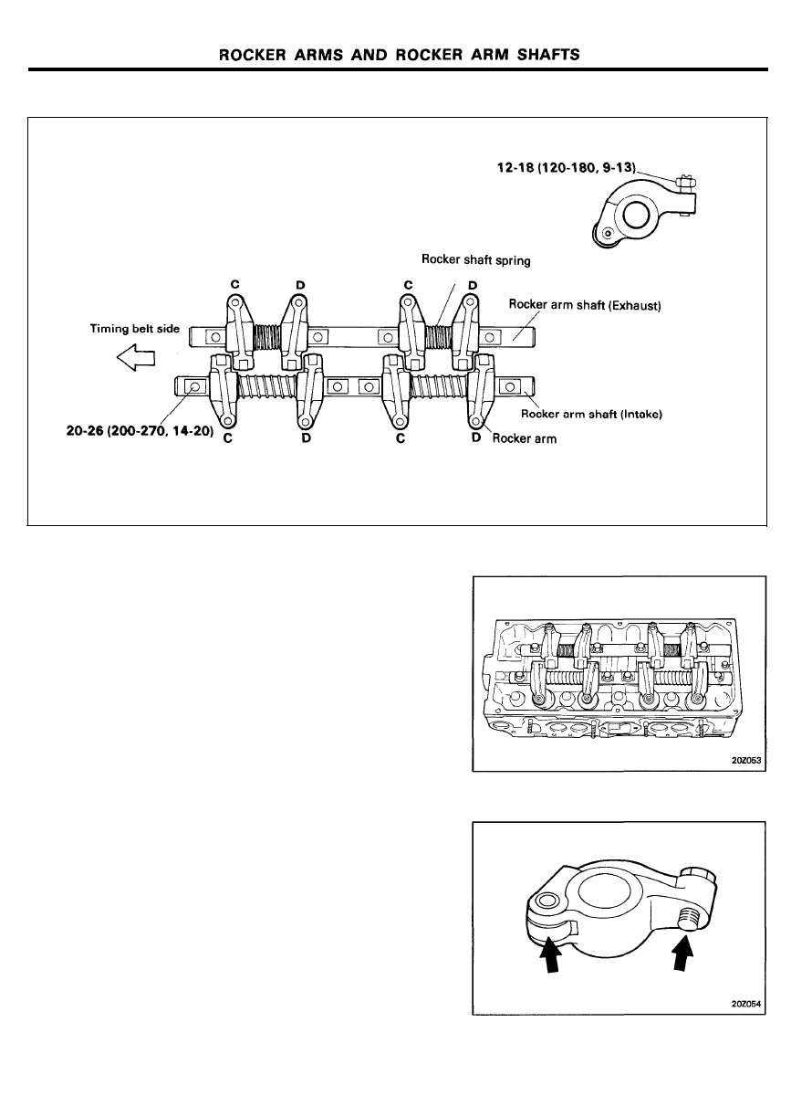
COMPONENTS [MPI]
C : Marked 1-3
TORQUE : Nm (kg.cm, lb.ft) D : Marked 2-4
REMOVAL
1.
Remove the breather hose between the air cleaner and the
rocker cover.
2. Remove the air cleaner.
3. Remove
the
timing
belt cover.
4. Remove the rocker cover.
5.
Loosen the rocker arm shaft mounting bolts and remove the
rocker arm shaft, rocker arms and rocker arm shaft springs
as an assembly.
6. Remove the bolts, the rocker arms and rocker arm shaft
springs from the rocker arm shaft.
INSPECTION
1. Check the roller surface. Replace there are any dents,
damage or evidence of seizure.
2.
Check rotation of the roller. If it does not rotate smoothly or
if looseness is evident, replace it.
3. Check the inside diameter. If damage or seizure is evident
replace the roller.
4.
Check the areas marked with arrows for wear and damage.
If considerable wear or damage is evident, replace the roller.
2 0 - 3 3
ROCKER ARMS AND ROCKER ARM SHAFTS
ROCKER ARMS AND ROCKER ARM SHAFTS
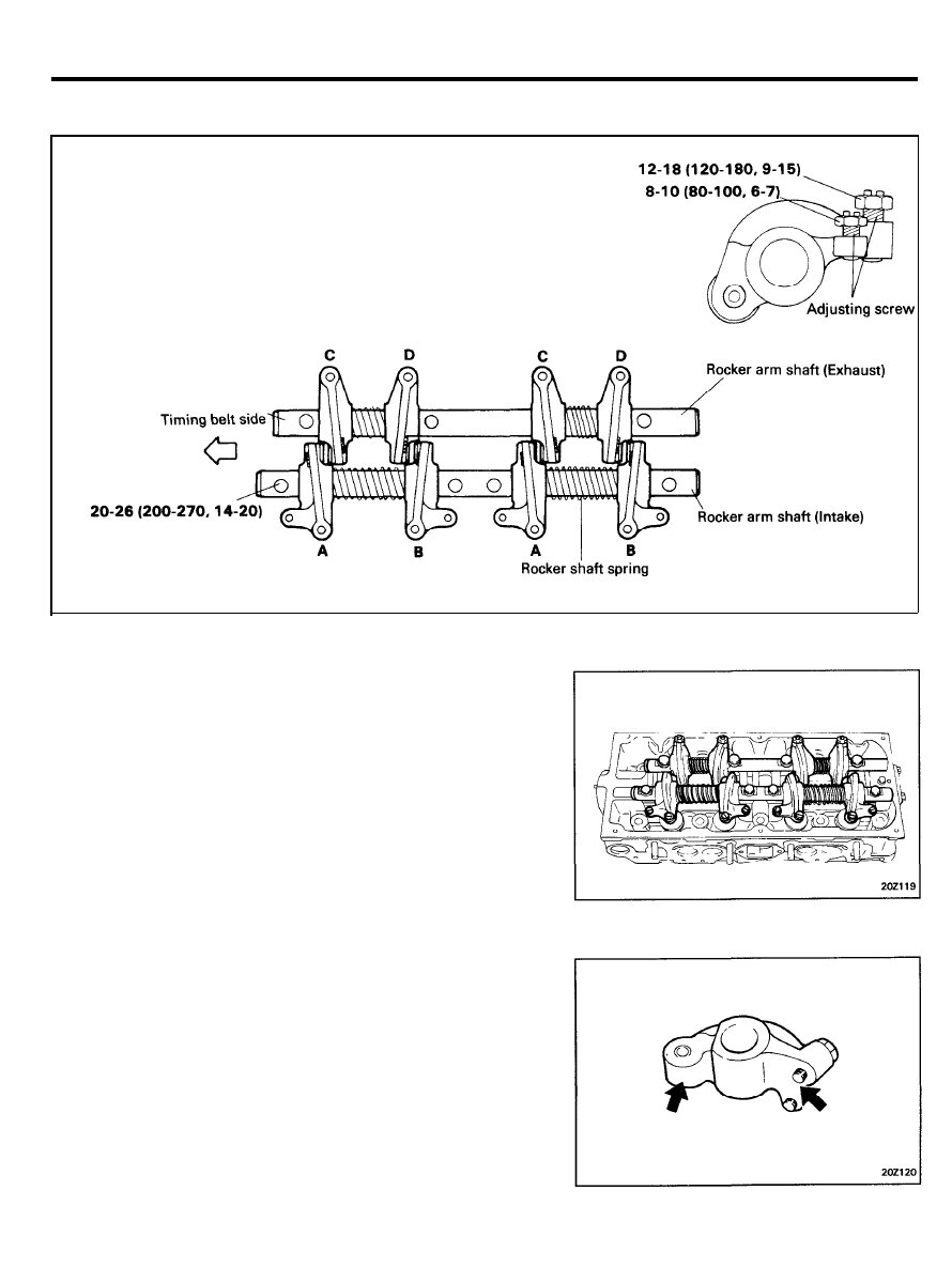
COMPONENTS [FBC]
TORQUE : Nm (kg.cm, lb.ft) A, C : Marked 1-3
B, D : Marked 2-4
REMOVAL
1.
Remove the breather hose between the air cleaner and the
rocker cover.
2. Remove the air cleaner.
3.
Remove the timing belt cover.
4. Remove the rocker cover.
5.
Loosen the rocker arm shaft mounting bolts and remove the
rocker arm shaft, rocker arms and rocker arm shaft springs
as an assembly.
6. Remove the bolts, the rocker arms and rocker arm shaft
springs from the rocker arm shaft.
INSPECTION
1. Check the rocker arm face that contacts the cam lobe and
the adjusting screw end that contacts the valve stem. If badly
worn or damaged, replace rocker arm and/or adjusting
screws.
2. Check the rocker arm shaft for damage. Replace as
necessary.
2 0 - 3 4
ROCKER ARMS AND ROCKER ARM SHAFTS
INSTALLATION
1.
Install the rocker arms and rocker arm shaft springs to the
rocker arm shafts. Install the rocker arm shafts to the
cylinder head.
Tighten the rocker arm shaft mounting bolts to the specified
torque.
Tightening torque
Rocker arm shaft mounting bolt. . . . . . . . . . . . . . . . . . . . . . .
20-26 Nm (200-270 kg.cm, 14-20 lb.ft)
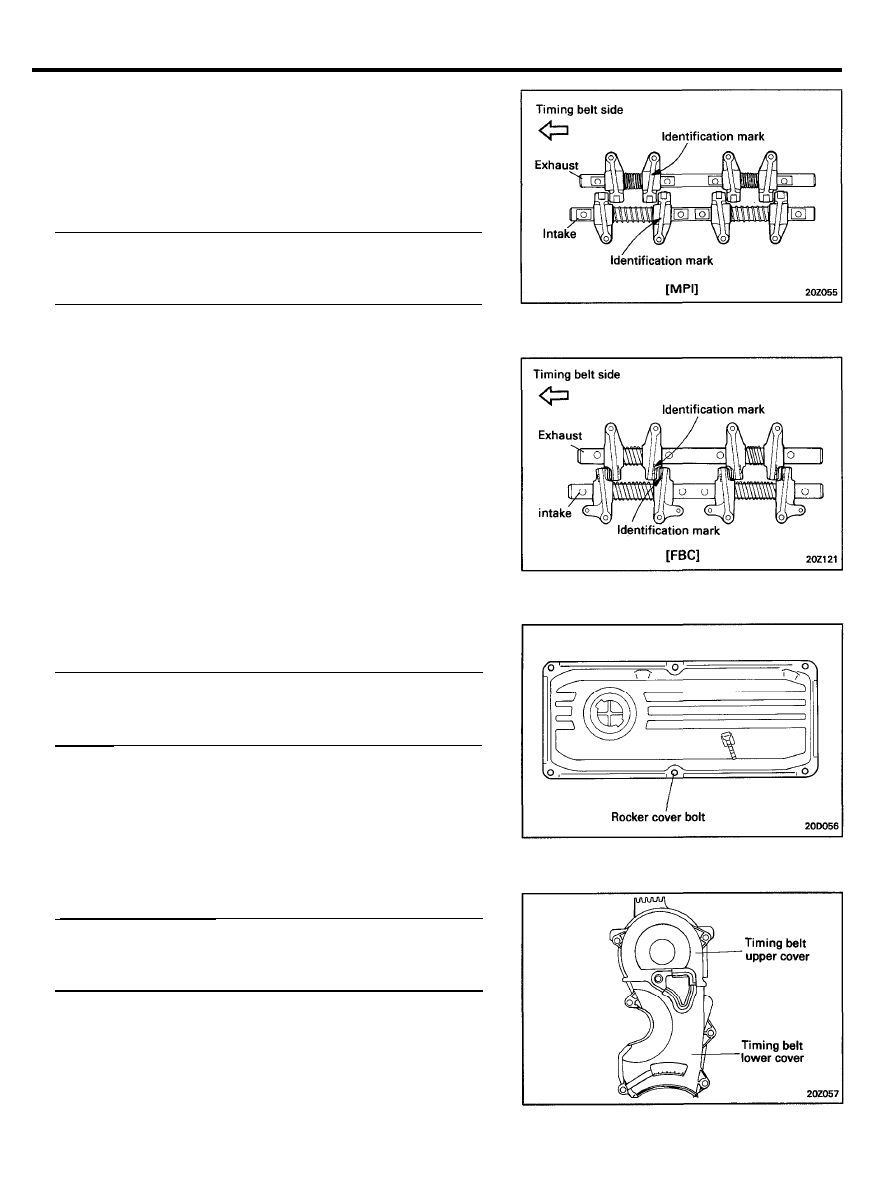
2.
When installing the rocker arms, shafts and springs, note the
difference between the RH and LH parts. The RH springs
(exhaust) are approx. 44.2 mm (1.74 in.) free length, while
the LH springs (intake) are approx. 77 mm (3.03 in.) free
length.
3.
Install the rocker cover and tighten the bolts to the specified
torque.
Tightening torque
Rocker cover bolt . . . . . . . . . . . . . . . . . . . . . . . . . . . . . . . .
1.5-2.0 Nm (15-20 kg.cm, 1.1-1.4 Ib.ft)
4. Install the timing belt cover.
Tightening torque
Timing belt cover bolt . . . . . . . . . . . . . . . . . . . . . . . . . . . . . . . .
10-12 Nm (100-120 kg.cm, 7.2-8.7 lb.ft)
5. Install the air cleaner.
6. Install the breather hose.
2 0 - 3 5
CAMSHAFT
COMPONENTS
TORQUE : Nm (kg.cm, lb.ft)
REMOVAL
1. Disconnect the breather hose and the secondary air hose.
2. Remove the air cleaner.
3. Remove the timing belt cover.
4.
Move the timing belt tensioner pulley toward the water pump
and temporarily secure it.
5. Remove the timing belt from the camshaft sprocket. Since
the crankshaft pulley need not be removed, the timing belt
should be left installed on the crankshaft sprocket.
6. Remove the camshaft sprocket.
7. Remove the rocker cover.
8. Remove the rocker arm shaft assembly. Refer to “Rocker
Arms and Rocker Arm Shafts”.
9. Remove the cylinder head rear cover.
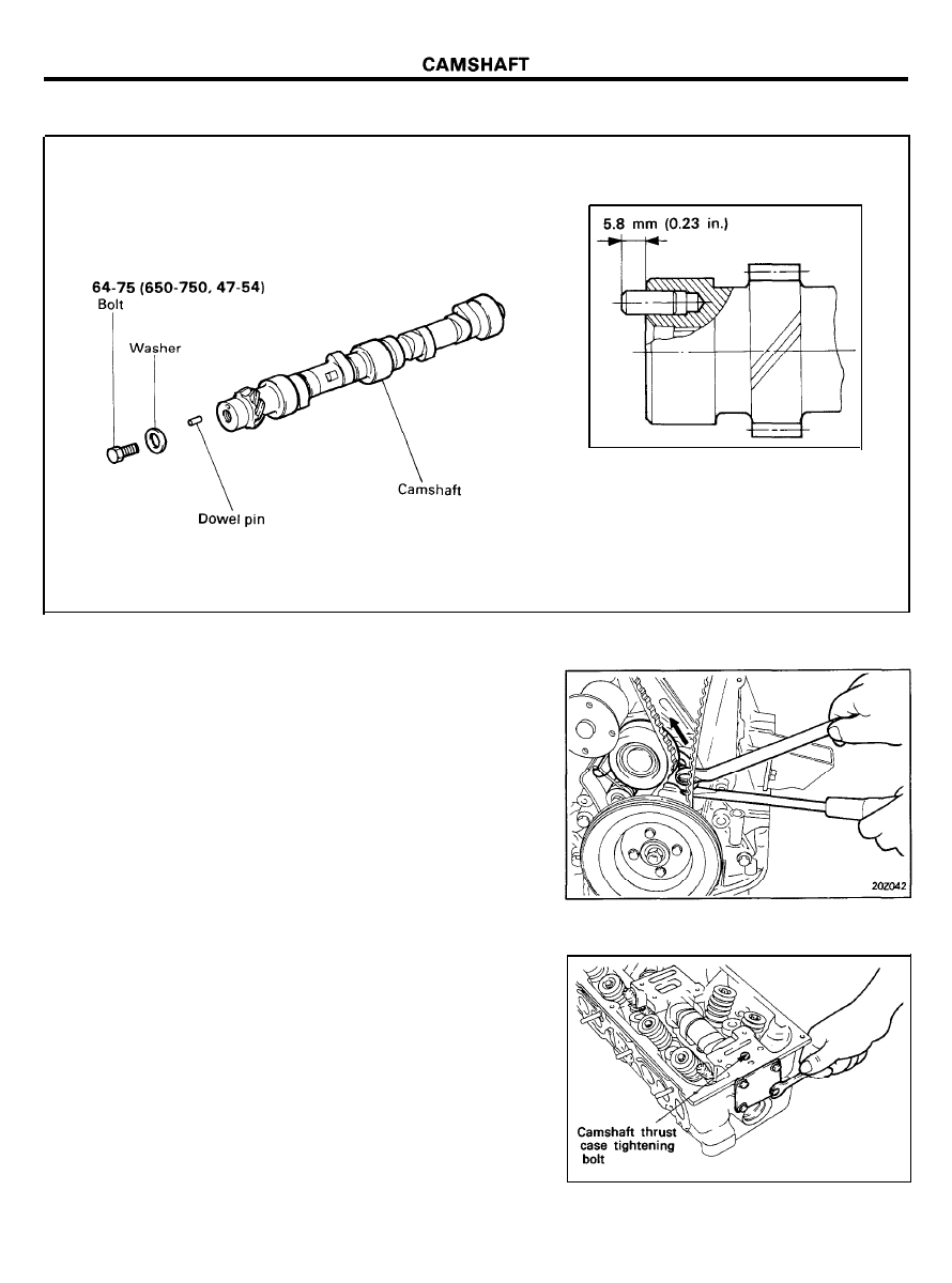
10. Remove the camshaft thrust case tightening bolt.
11. Remove the camshaft thrust case and camshaft toward the
transaxle side of the cylinder head.
2 0 - 3 6
CAMSHAFT
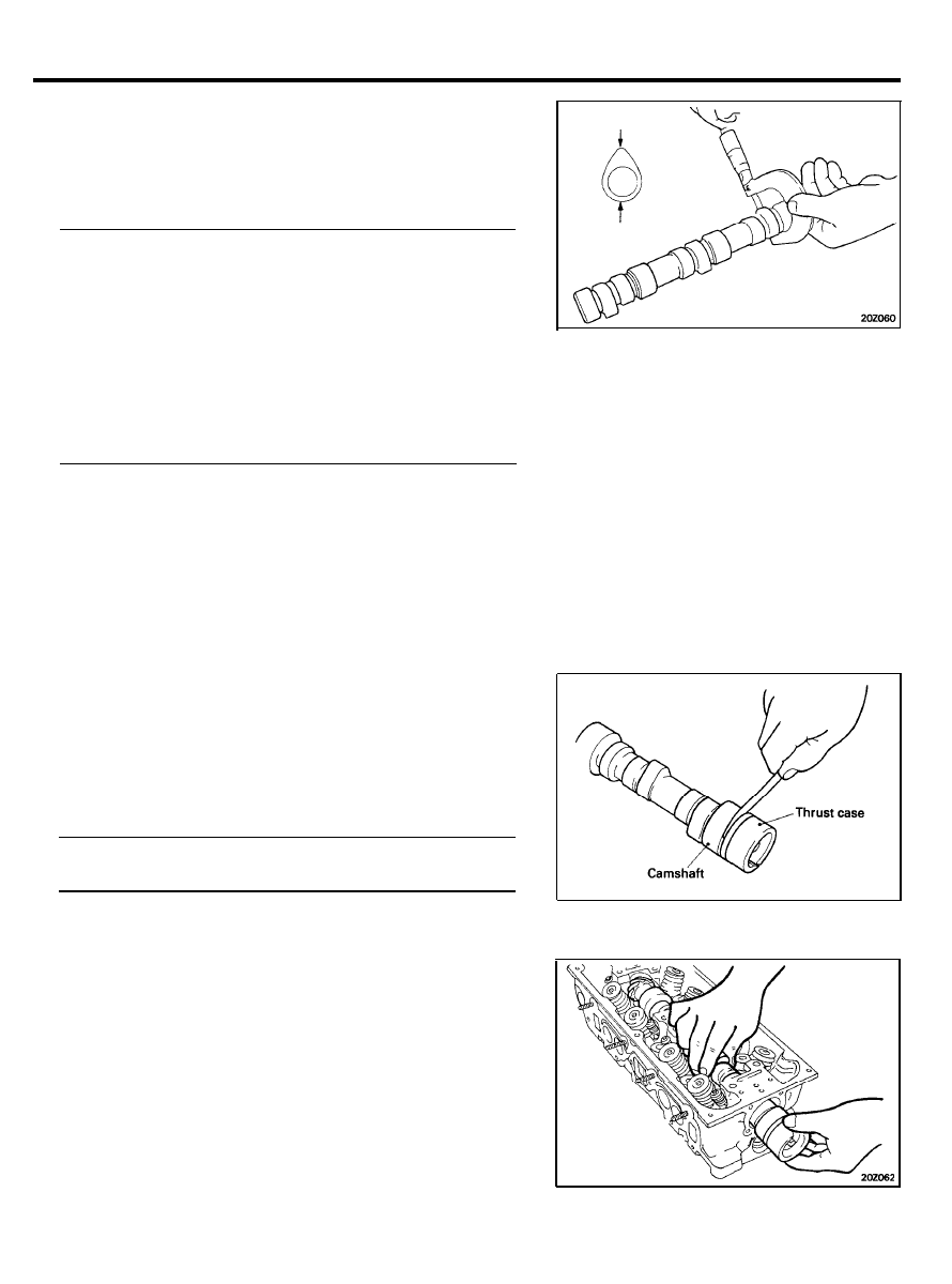
INSPECTION
1. Check the camshaft journals for wear. If the journals are
badly worn, replace the camshaft.
2.
Check the cam lobes for damage. If the lobe is damaged or
worn excessively, replace the camshaft.
Cam height
[Standard] [MPI]
Intake. . . . . . . . . . . . . . . . . . . . . . 38.909 mm (1.5318 in.)
Exhaust. . . . . . . . . . . . . . . . , . . . . 38.947 mm (1.5344 in.)
[Standard] [FBC]
Intake. . . . . . . . . . . . . . . . . . . . . . 38.909 mm (1.5318 in.)
Exhaust. . . . . . . . . . . . . . . . . . . . 38.648 mm (1.5216 in.)
[Limit]
Intake . . . . . . . . . . . . . . . . . . . . . . . . -0.5 mm (-0.020 in.)
Exhaust. . . . . . . . . . . . . . . . . . . . . -0.5 mm (-0.020 in.)
3.
Check the cam surface for abnormal wear or damage, and
replace if necessary.
4.
Check the distributor drive gear tooth surfaces. If abnormal
wear is evident, replace the camshaft.
5. Check each bearing for damage. If the bearing surface is
excessively damaged, replace the cylinder head assembly.
6. Oil Seal (camshaft front)
1)
Check the lips for wear. If lip threads are worn, replace.
2) Check the oil seal lip contacting surface of camshaft. If
it is worn in stages, replace the camshaft.
7. Check the camshaft end play.
If the end play is too large, replace the thrust case and
recheck the end play. If the end play is still too large, check
the rear end of camshaft rear journal for wear. If it is badly
worn, replace the camshaft.
End play of camshaft [Standard value] . . . . . . . . . . . . . . . . . .
0.05-0.20 mm (0.002-0.008 in.)
INSTALLATION
1. Install the crankshaft thrust case and thrust plate to the
camshaft end and firmly tighten the bolt.
2 0 - 3 7
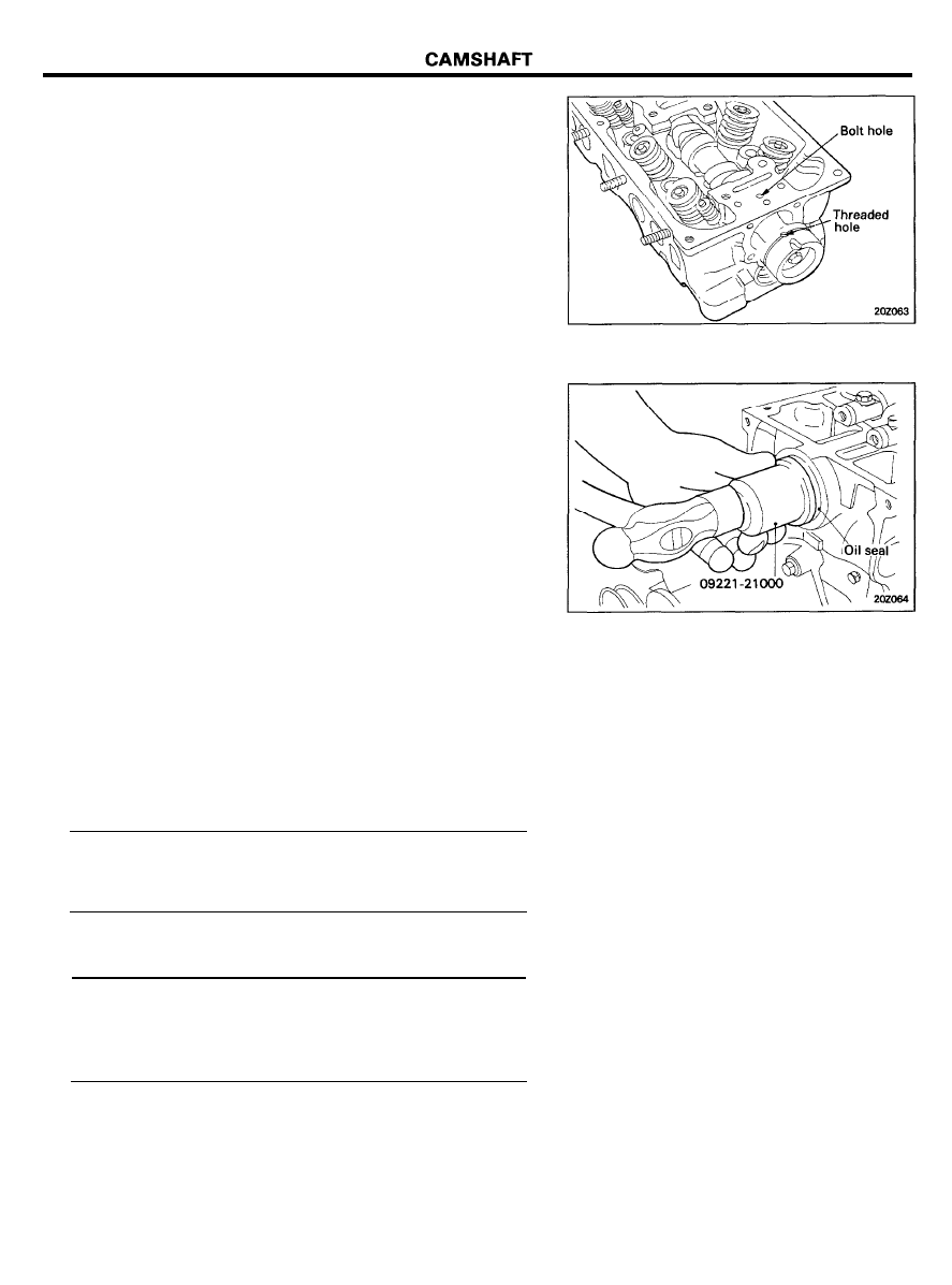
2. After lubricating the journal and thrust portions of the
camshaft with engine oil, insert the camshaft from the
transaxle side of the cylinder head. Insert the camshaft
thrust case with the threaded hole at the top. Align the
threaded hole with the bolt hole in the cylinder head. Install
and tighten the bolt.
3. Install the rear cover and gasket and tighten the bolts.
4. Using special tools, Camshaft Oil Seal Installer (09221-
21000), press fit the camshaft oil seal. Be sure to apply
engine oil to the external surface of the oil seal.
Insert the oil seal along the camshaft front end and install
by driving the installer with a hammer until the oil seal is
fulley seated.
5. Install the camshaft sprocket and tighten the bolts to the
specified torque.
6. Install the rocker arm and shafts.
Refer to “Rocker Arms and Rocker Arm Shafts”.
7.
Align the camshaft sprocket and crankshaft sprocket timing
marks. The piston in the No. 1 cylinder will then be at the
top dead center on the compression stroke.
Tightening torque
Camshaft sprocket bolt . . . . . . . . . . . . . . . . . . . . . . . . . . . . . . .
64-74 Nm (650-750 kg.cm, 47-54 lb.ft)
8.
Temporarily set the valve clearance to specification with the
engine cold. See “Valve Clearance Adjustment Procedure”.
Valve clearance (cold engine) [Standard value]
Intake valve . . . . . . . . . . . . . . . . . . . . . 0.07 mm (0.003 in.)
Exhaust valve . . . . . . . . . . . . . . . . . . . 0.17 mm (0.007 in.)
Jet valve [FBC only] . . . . . . . . . . . . . . 0.17 mm (0.007 in.)
2 0 - 3 8

CAMSHAFT
9. Install a gasket in the rocker cover groove.
10. Temporarily install the rocker cover.
11. Start the engine and run at idle.
12. After warming the engine to normal operating temperature
[80 to 95°C (176 to 205°F) coolant temperature], adjust the
valve clearance to specification. See “Valve Clearance
Adjustment Procedure”.
13. Install the rocker cover and tighten the bolts to the specified
torque.
Tightening torque
Rocker cover bolt . . . . . . . . . . . . . . . . . . . . . . . . . . . . . . . . . . . . .
1.5-2.0 Nm (15-20 kg.cm, 1.1-1.4 lb.ft)
14. Install the timing belt cover.
2 0 - 3 9
CYLINDER HEAD
CYLINDER HEAD
COMPONENTS
TORQUE : Nm (Kg.cm, lb.ft)
REMOVAL
1. Drain the coolant and disconnect the upper radiator hose.
2.
Remove the breather hose (between the air cleaner and the
rocker cover).
3.
Remove the air cleaner.
4. Remove the vacuum hose, fuel hose and water hose.
5.
Remove the cables from the spark plugs. The cables should
be removed by holding their boot portions.
2 0 - 4 0
CYLINDER HEAD
6. Remove the distributor.
7. Remove the surge tank.
8. Remove the intake manifold.
9. Remove the heat cowl and exhaust manifold assembly.
10. Remove the timing belt cover.
11. Move the timing belt tensioner pulley toward the water
pump and temporarily secure it.
12. Remove the timing belt from the camshaft sprocket. Since
the crankshaft pulley need not be removed, the timing belt
should be left on the crankshaft sprocket.
13. Remove the rocker cover.
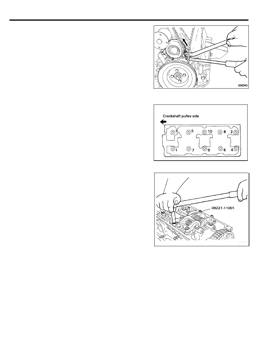
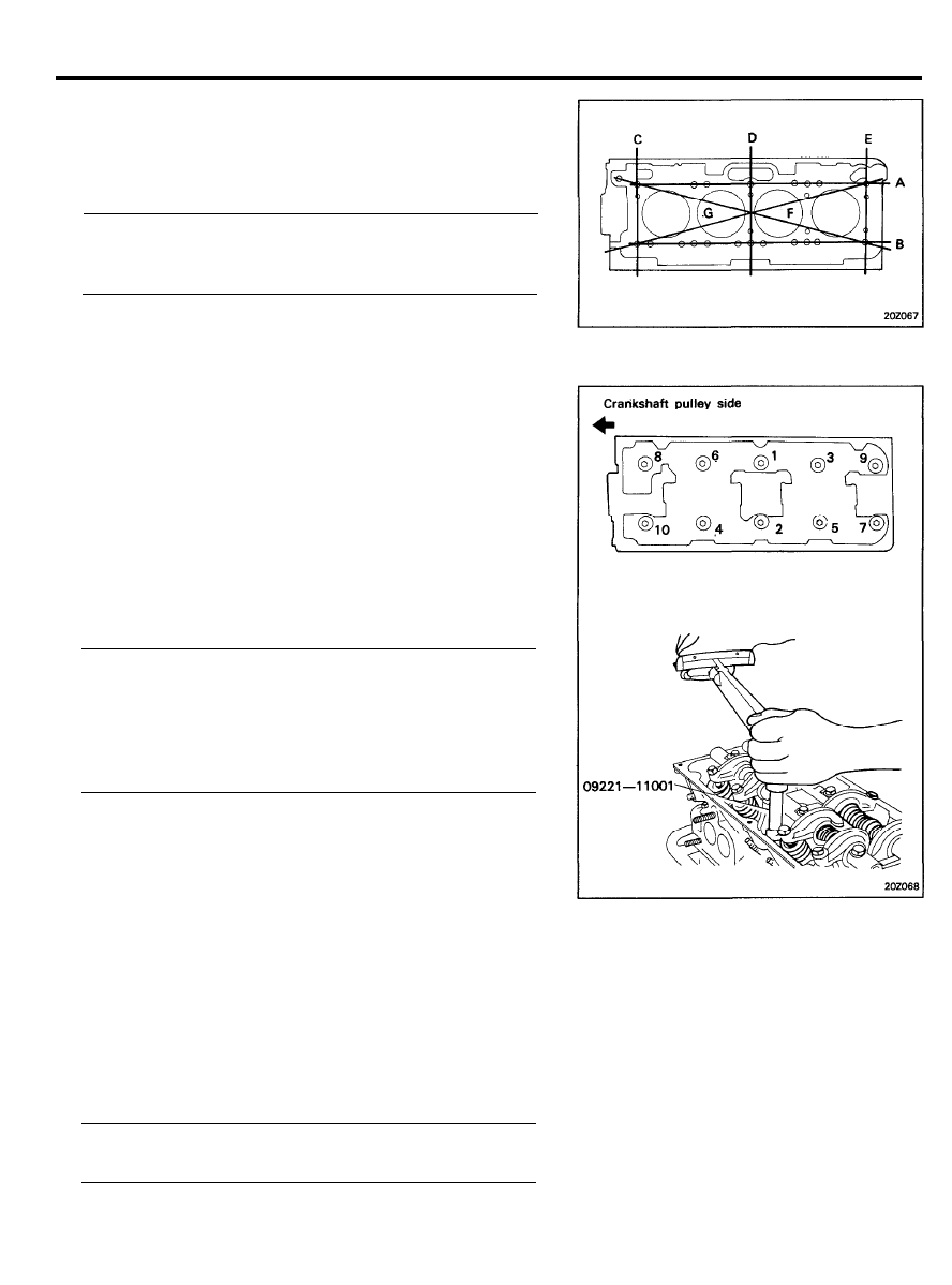
14. Remove the cylinder head assembly. The cylinder head bolts
should be removed by using Special Tool, Cylinder Head Bolt
Wrench (09221-11001), in the sequence as shown in the
illustration.
15. Remove the gasket pieces from the cylinder block top surface
and cylinder head bottom surface.
NOTE
Make sure that the gasket pieces do not fall in the engine.
INSPECTION
1. Check the cylinder head for cracks, damage and coolant
leakage.
2. Remove scale, sealing compound and carbon deposits
completely. After cleaning oil passages, apply compressed air
to make certain that the passages are not clogged.
3. Check the EGR gas passage for clogging.
And for FBC system, also check the jet air passage for
clogging.
2 0 - 4 1
CYLINDER HEAD
4.
Check the cylinder head gasket surface for flatness by using
a straight edge in the direction of A, B, . . . as shown.
If flatness exceeds service limit in any direction, either
replace the cylinder head, or lightly machine the cylinder
head gasket surface.
Flatness of cylinder head gasket surface
[Standard dimension] . . . . . Less than 0.05 mm (0.002 in.)
[Limit]. . . . . . . . . . . . . . . . . . . . . . . . . . . . . . . . 0.1 mm (0.004 in.)
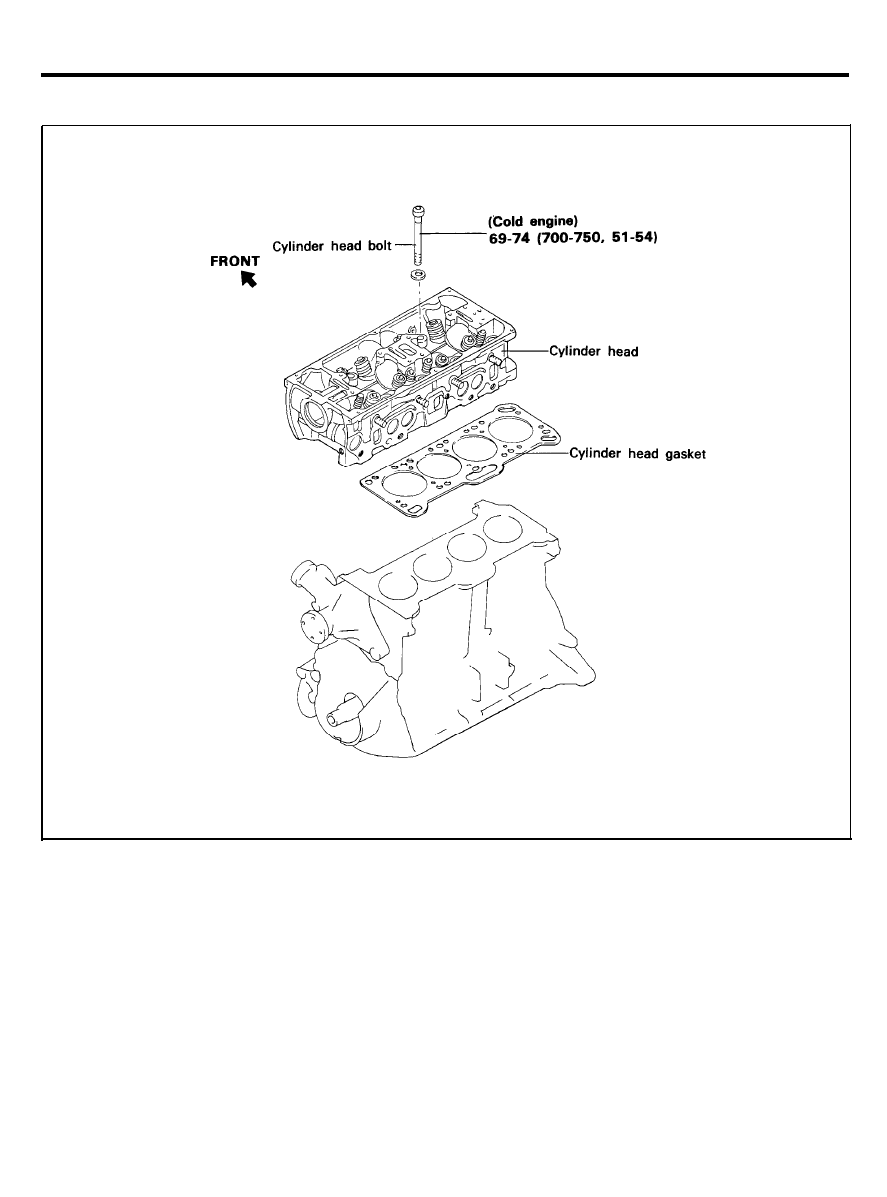
INSTALLATION
1. Clean all gasket surfaces of the cylinder block and the
cylinder head.
2. Install a new cylinder head gasket onto the cylinder head
assembly. Do not apply sealant to the gasket and do not
reuse the old cylinder head gasket.
3.
Install the cylinder head bolts. Starting at top center, tighten
all cylinder head bolts in sequence as shown in illustration,
using the Cylinder Head Bolt Wrench (09221-11001).
Repeat the procedure, retightening all cylinder head bolts to
the specified torque.
Tightening torque
Cylinder head bolt
Cold . . . . . . . . . . . . . . . . . . . . . . . . . . . . . . . . . . . . . . . . . . . . . . .
69-74 Nm (700-750 kg.cm, 51-54 lb.ft)
Hot . . . . . . . . . . . . . . . . . . . . . . . . . . . . . . . . . . . . . . . . . . . . . . . .
78-83 Nm (800-850 kg.cm, 58-61 lb.ft)
4.
Move the timing belt tensioner pulley toward the water pump
and temporarily secure it.
5.
Install the timing belt on the camshaft sprocket, making sure
that the tension side is tight. Check to ensure that when the
tension side is tightened by turning the camshaft sprocket
in reverse, all timing marks are in alignment.
6. Adjust the timing according to “Timing Belt”.
7.
Install the rocker cover and tighten the bolts to the specified
torque.
Rocker cover bolt Tightening torque . . . . . . . . . . . . . . . . . . . . .
1.5-2.0 Nm (15-20 kg.cm, 1.1-1.4 lb.ft)
2 0 - 4 2

CYLINDER HEAD
8. Install the timing belt cover.
9. Install the new intake manifold gasket and the intake
manifold. Tighten the nuts and bolts to the specified torque.
Tightening torque
Manifold nuts and bolts . . . . . . . . . . . . . . . . . . . . . . . . . . . . . .
(both intake and exhaust)
15-20 Nm (150-200 kg.cm, 11-14 lb.ft)
10. Install the new exhaust manifold gasket and the exhaust
manifold. Tighten the exhaust manifold attaching nuts to the
specified torque.
11. Install the surge tank and tighten the nuts and bolts to the
specified torque.
For carburetor type, install the carburetor and tighten the
bolts to the specified torque.
Tightening torque
Surge tank to inlet manifold nuts and bolts . . . . . . . . . . .
15-20 Nm (150-200 kg.cm, 11-14 lb.ft)
Carburetor to intake manifold bolts. . . . . . . . . . . . . . . . . . .
15-20 Nm (150-200 kg.cm, 11-14 lb.ft)
12. Install the distributor.
13. Connect the vacuum hose, fuel hose and water hose.
14. Install the air cleaner and breather hose.
2 0 - 4 3
VALVES AND VALVE SPRINGS
VALVES AND VALVE SPRINGS
TORQUE : Nm (kg.cm, lb.ft)
REMOVAL
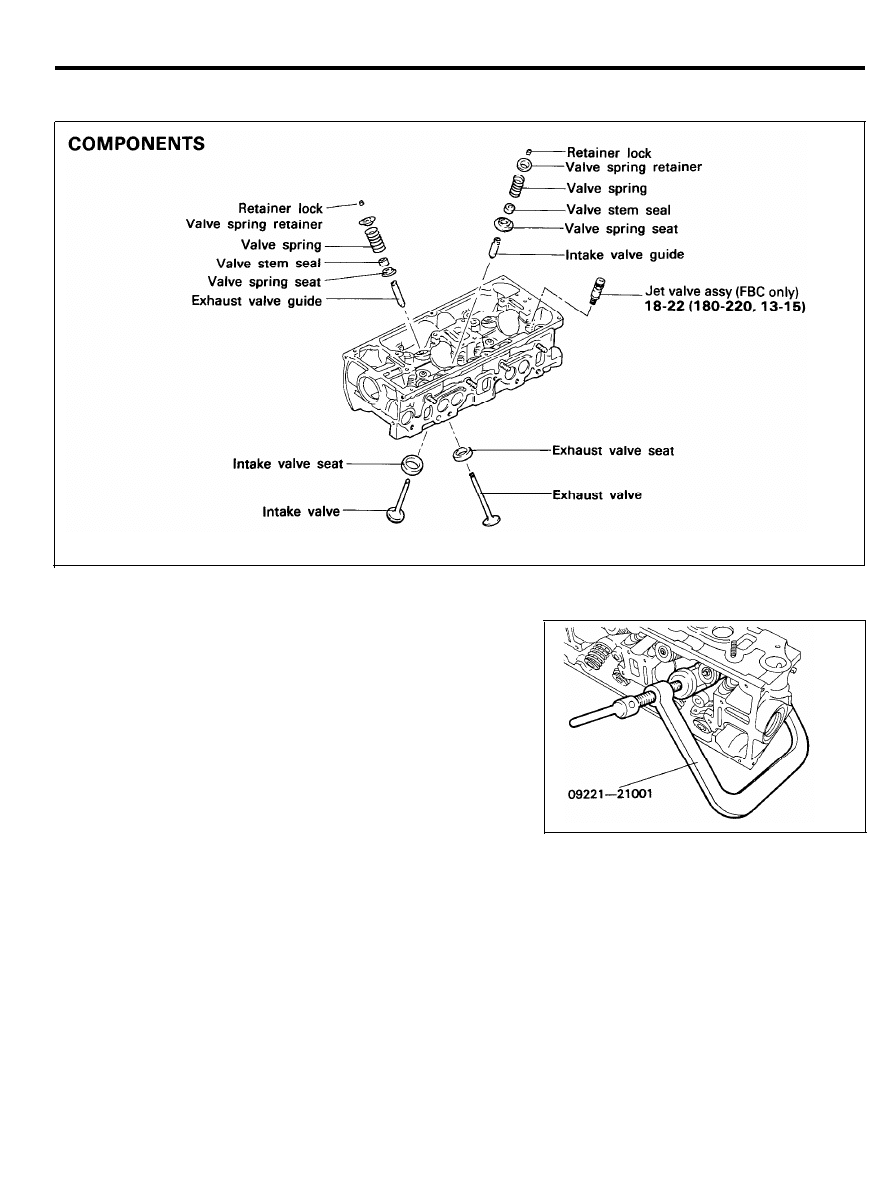
1. Using Special Tool, Valve Spring Compressor (09222-
21001), remove the retainer lock.
Next remove the spring retainer, valve spring, spring seat
and valve.
NOTE
Keep these parts in order so that they can be reinstalled
in their original positions.
2. Remove the valve stem seals with pliers, and discard.
NOTE
Do not reuse the valve stem seals.
2 0 - 4 4
VALVES AND VALVE SPRINGS
INSPECTION
Valves
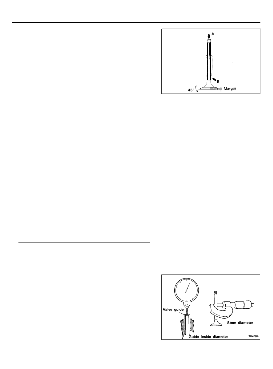
Check each valve for wear, damage and distortion of head and
stem at B. Repair or correct if necessary.
If stem end A is pitted or worn, resurface as necessary. This
correction must be limited to a minimum. Also resurface the
valve face.
Replace the valve if the margin has decreased to less than the
service limit.
Margin
[Standard dimension]
Intake . . . . . . . . . . . . . . . . . . . . . . . . . . . . . . . 1.0 mm (0.039 in.)
Exhaust . . . . . . . . . . . . . . . . . . . . . . . . . . . . . 1.5 mm (0.059 in.)
[Limit]
Intake . . . . . . . . . . . . . . . . . . . . . . . . . . . . . . . 0.7 mm (0.028 in.)
Exhaust . . . . . . . . . . . . . . . . . . . . . . . . . . . . . 1.0 mm (0.039 in.)
Valve Springs
1. Check the valve spring free length and tension. If they
exceed the service limit, replace the spring.
2. Using a square, test the squareness of each spring. If the
spring is excessively out of square, replace it.
Valve spring
[Standard Value]
Free height . . . . . . . . . . . . . . . . . . . . . 44.6 mm (1.756 in.)
Load . . . . . . . . . .24 kg at 27.3 mm (53 lb at 1.075 in.)
Out of square . . . . . . . . . . . . . . . . . . . . . . . . . . . 1.50 or less
[Limit]
Free height . . . . . . . . . . . . . . . . . . -1.0 mm (-0.039 in.)
Out of square . . . . . . . . . . . . . . . . . . . . . . . . . . . . . . . . . . . .
3°
Valve Guides
Check the valve stem-to-guide clearance. If the clearance
exceeds the service limit, replace the valve guide with next
oversize part.
Valve stem-to-guide clearance
[Standard dimension]
Intake . . . . . . . . . . . . . . 0.03-0.06 mm (0.0012-0.0024 in.)
Exhaust . . . . . . . . . . . . 0.05-0.09 mm (0.0020-0.0035 in.)
[Limit]
Intake . . . . . . . . . . . . . . . . . . . . . . . . . . . . . . . 0.1 mm (0.004 in.)
Exhaust . . . . . . . . . . . . . . . . . . . . . . . . . . . . 0.15 mm (0.006 in.)
2 0 - 4 5
VALVES AND VALVE SPRINGS
Valve Guide Oversizes
Size mm (in.)
Size mark
Cylinder head hole size
mm (in.)
0.05 (0.002) O.S
5
12.105-12.115
(0.4766-0.4770)
0.25 (0.010) O.S
25
12.305-12.315
(0.4844-0.4848)
0.50 (0.020) O.S
50
12.555-12.565
(0.4943-0.4947)
Valve Seat Insert
Check the valve seat for evidence of overheating and improper
contact with the valve face. Recondition or replace the seat if
necessary.
Before reconditioning the seat, check the valve guide for wear.
If the valve guide is worn, replace it, then recondition the seat.
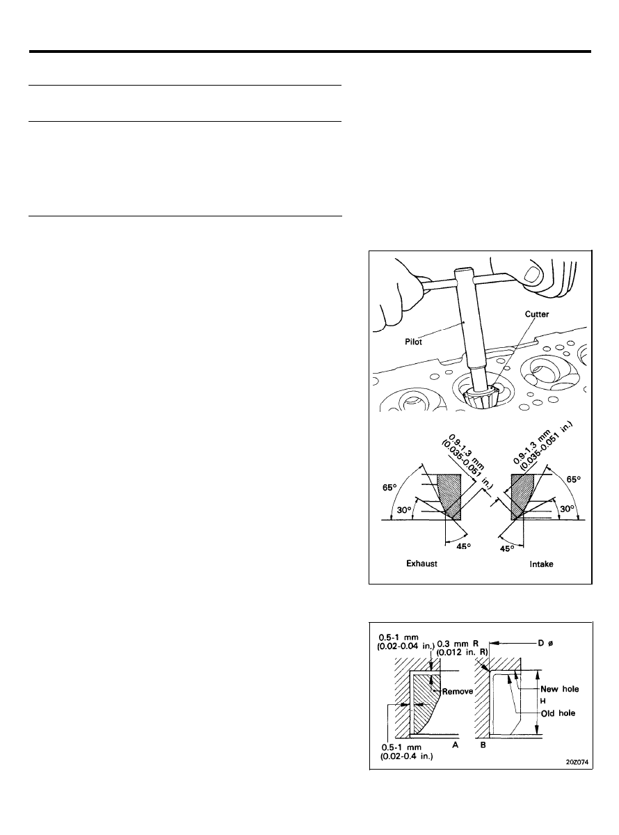
Recondition the valve seat with a valve seat grinder or cutter.
The valve seat contact width should be within specifications and
centered on the valve face.
Valve Seat Insert Replacement Procedure
1. Any valve seat insert that has been worn over the service
limit should be removed at normal temperature after cutting
away most of the insert wall, using valve seat cutters, as
shown in Fig. “A”.
2 0 - 4 6

VALVES AND VALVE SPRINGS
Valve Seat Insert Oversizes
Description
Size mm (in.) Size mark Seat insert height H mm (in.)
Cylinder head I.D. mm (in.)
Intake valve
0.3 (0.012) O.S
30
7 . 0 - 7 . 2 (0.276-0.283)
3 6 . 3 0 - 3 6 . 3 3 (1.429-1.430)
seat insert
0.6 (0.024) O.S
60
7 . 3 - 7 . 5 (0.287-0.295)
3 6 . 6 0 - 3 6 . 6 3 (1.441-1.442)
Exhaust valve
0.3 (0.012) O.S
30
7 . 4 - 7 . 6 (0.291-0.299)
3 2 . 3 0 - 3 2 . 3 3 (1.272-1.273)
seat insert
0.6 (0.024) O.S
60
7 . 7 - 7 . 9 (0.303-0.311)
3 2 . 6 0 - 3 2 . 6 3 (1.283-1.285)
2.
After removing the seat insert, machine the seat insert bore
using a reamer or a cutter. Cut to the size shown in the table.
3.
Heat the cylinder head to about 250°C (480°F) and press in
the oversize seat insert. The oversize seat insert should be
at normal room temperature for installation. After installation
of a new valve seat insert, resurface the valve seat using
the same procedure as in paragraph 1. in Valve Seat Insert.
2 0 - 4 7
VALVES AND VALVE SPRINGS
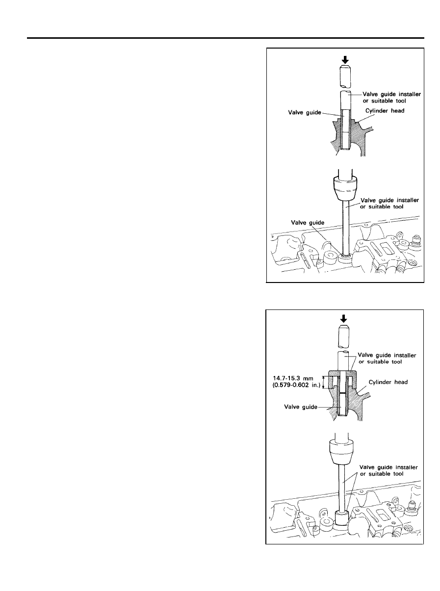
Valve Guide Replacement Procedures
The valve guide is installed using a press fit. Using a Valve Guide
Installer (09222-21200) or suitable tool, replace the valve guide
by the following procedure.
1.
2.
3.
4.
5.
Using the push rod of the Valve Guide Installer, push the
valve guide out toward the cylinder block with a press.
Machine the valve guide insert hole in the cylinder head to
the specified oversize of the new valve guide.
Using the Valve Guide Installer or suitable tool, press fit the
valve guide. The use of the valve guide installer makes it
possible to press fit the valve guide to a predetermined
height. The valve guide should be installed from the top of
the cylinder head. Note that the intake and exhaust valve
guides are different in length [44 mm (1.73 in.) for intake
and 49.5 mm (1.95 in.) for exhaust].
After the valve guides have been installed, insert new valves
and check the clearance.
Whenever valve guides are replaced, check for valve to seat
contact and recondition the valve seats as necessary.
2 0 - 4 8
VALVES AND VALVE SPRINGS
INSTALLATION
CAUTION
1) Clean each part before assembly.
2) Apply engine oil to sliding and rotating parts.
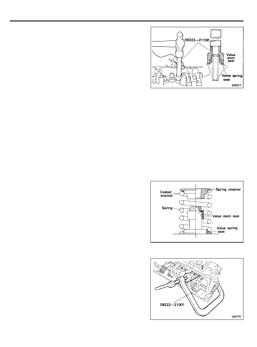
1. After installing the spring seat, fit the stem seal onto the
valve guide.
To install, fit the seal in by lightly tapping the Special Tool,
Valve Stem Oil Seal Installer (09222-21100).
The seal’ is installed in the specified position by
means
of
the special tool. Incorrect installation of the seal will
adversely affect the lip I.D. and eccentricity, resulting in oil
leakage down the valve guides. When installing, therefore,
be careful not to twist the seal. Do not reuse old stem seals.
2. Apply engine oil to each valve. Insert the valves into the
valve guides. Avoid inserting the valve into the seal with
force.
After insertion, check to see if the valve moves smoothly.
3.
4.
5.
Install springs and spring retainers.
Valve springs should be installed with the enamel coated
side toward the valve spring retainer.
Using Special Tool, Valve Spring Compressor (09222-
21001), compress the spring. Be careful that the valve stem
seal is not distorted by the bottom of the retainer. Then
install the retainer locks. After installation of the valves,
make certain that the retainer locks are properly installed.
Install the cylinder head. Refer to “Cylinder Head”.
JET VALVE (FBC)
JET VALVE
COMPONENTS
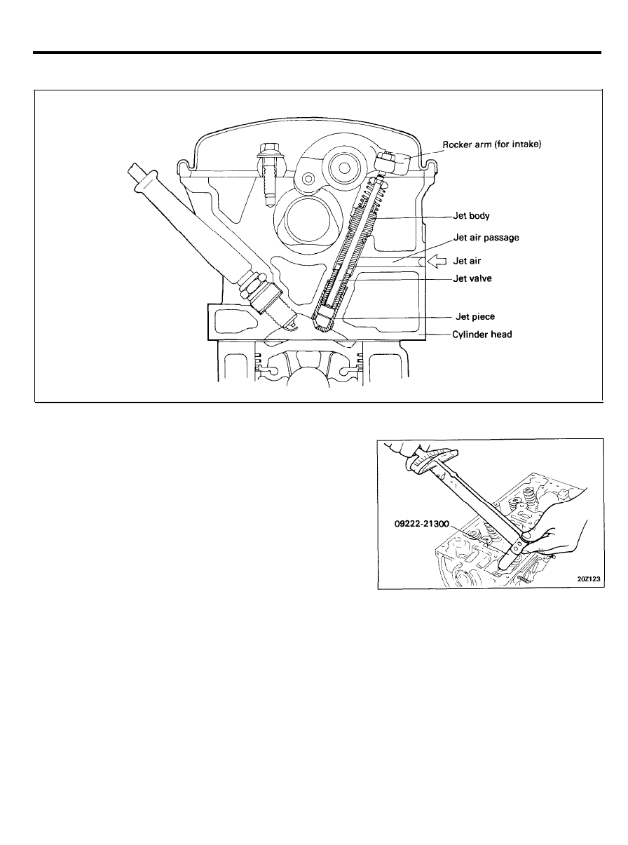
REMOVAL
1.
Remove the rocker arms and shafts. Refer to Rocker Arm and
Rocker Arm Shaft.
2. Remove the valves, using Special Tool, Jet Valve Socket
Wrench (09222-21300).
CAUTION
When the jet valve socket wrench is used, make certain that
the wrench is not tilted with respect to the center of the jet
valve. If the tool is tilted, the valve stem might be bent by
the force exerted on the valve spring retainer, resulting in
defective jet valve operation or a damaged tool.
2 0 - 5 0
JET VALVE (FBC)
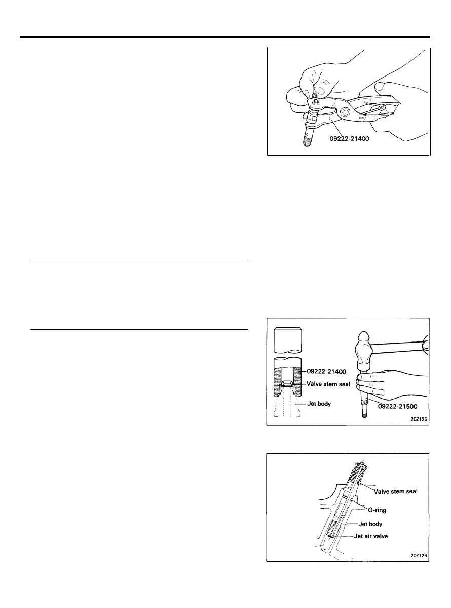
3.
When disassembling the jet valve, compress the spring with
the Special Tool, Jet Valve Spring Pliers (09222-21400)
remove the valve spring retainer lock, and then remove the
valve spring retainer and valve spring.
CAUTION
Do not mix up the combination of the jet valve body after
the disassembly of the jet valve assembly, otherwise gas
leakage and malfunctioning may result.
4. Pull off valve stem seals with pliers and discard.
INSPECTION
1.
Make sure that the jet valve slides smoothly in the body and
has no play.
Combination of the jet valve and jet body should not be
disturbed and the jet valve and jet body should be replaced
as an assembly.
2.
Check the valve head and valve seat for damage of seizure.
3. Check the spring for sag, cracks or breakage.
[Standard value]
Diameter of jet valve stem 4.300 mm (0.1693 in.)
Angle of valve face and seat . . . . . . . . . . . . . . . . . . . . . . 45°
Jet valve spring
Free length . . . . . . . . . . . . . . . . . . . 29.60 mm (1.165 in.)
Load . . . . . . . . . . . . . . 3.5 kg/21.5 mm (5.5 lb/0.846 in.)
INSTALLATION
1. Using the Special Tool, Jet Valve Stem Seal Installer
(09222-21500). drive the valve stem seal into the jet body.
CAUTION
1) The valve stem seal is not reusable.
2) Use Special Tool, otherwise valve stem seal will be
improperly installed and oil will work down.
2.
Apply engine oil to the jet valve stem when installing it to
the jet body. Take care not to damage the valve stem seal
lip. Make sure that the jet valve stem slides smoothly in the
body.
3.
Compress the spring with the Special Tool, Jet Valve Spring
Pliers (09222-21400) and install it together with valve
spring retainer, and install the retainer lock.
Be careful not to damage the valve stem seal with bottom
of the retainer while installing.
4.
Install new O-ring in the jet valve body groove and apply a
thin coat of engine oil to it.
2 0 - 5 1
JET VALVE (FBC)
5.
Install the jet valve assembly, assembled as described in 1
thru 4 above, using Special Tool, Jet Valve Socket Wrench
(09222-21300).
Tighten to the specified torque below. While installing, apply
engine oil to the threaded portion and seating surface of the
jet body.
CAUTION
1) Install the jet valve assembly, finger-tighten and finally
tighten to the specified torque with torque wrench.
2) Keep the socket of wrench aligned with the jet valve
stem to prevent it from forcing the stem sidewise or
to keep it from dropping.
Tightening torque
Jet valve assembly . . . . . . . . . . . . . . . . . . . . . . . . . . . . . . . . . . .
18-22 Nm (180-220 kg.cm, 13-16 lb.ft)
6.
Install the rocker arm shaft assembly and rocker cover. Refer
to “Rocker Arm Shaft Assembly”.
JET VALVE CLEARANCE ADJUSTMENT
CAUTIONS
1) The misadjustment of the jet valve clearance not only
2)
3)
1.
2.
3.
4.
5.
affects the exhaust gas level but also may cause some
engine trouble. So, be sure to make adjustment as follows:
Adjust the jet valve clearance before the adjustment of the
intake valve clearance. Readjust it after additional
tightening of cylinder head bolts.
Loosen fully the adjusting screws while making jet valve
clearance adjustment.
Warm up the engine until the temperature of the coolant
rises to 80 to 95°C (176 to 205°F).
With the piston in the cylinder positioned at TDC on the
compression stroke, adjust in the following sequence.
Back off the adjusting screw for the intake valve 2 or more
turns.
Loosen the lock nut on the adjusting screw for the jet valve.
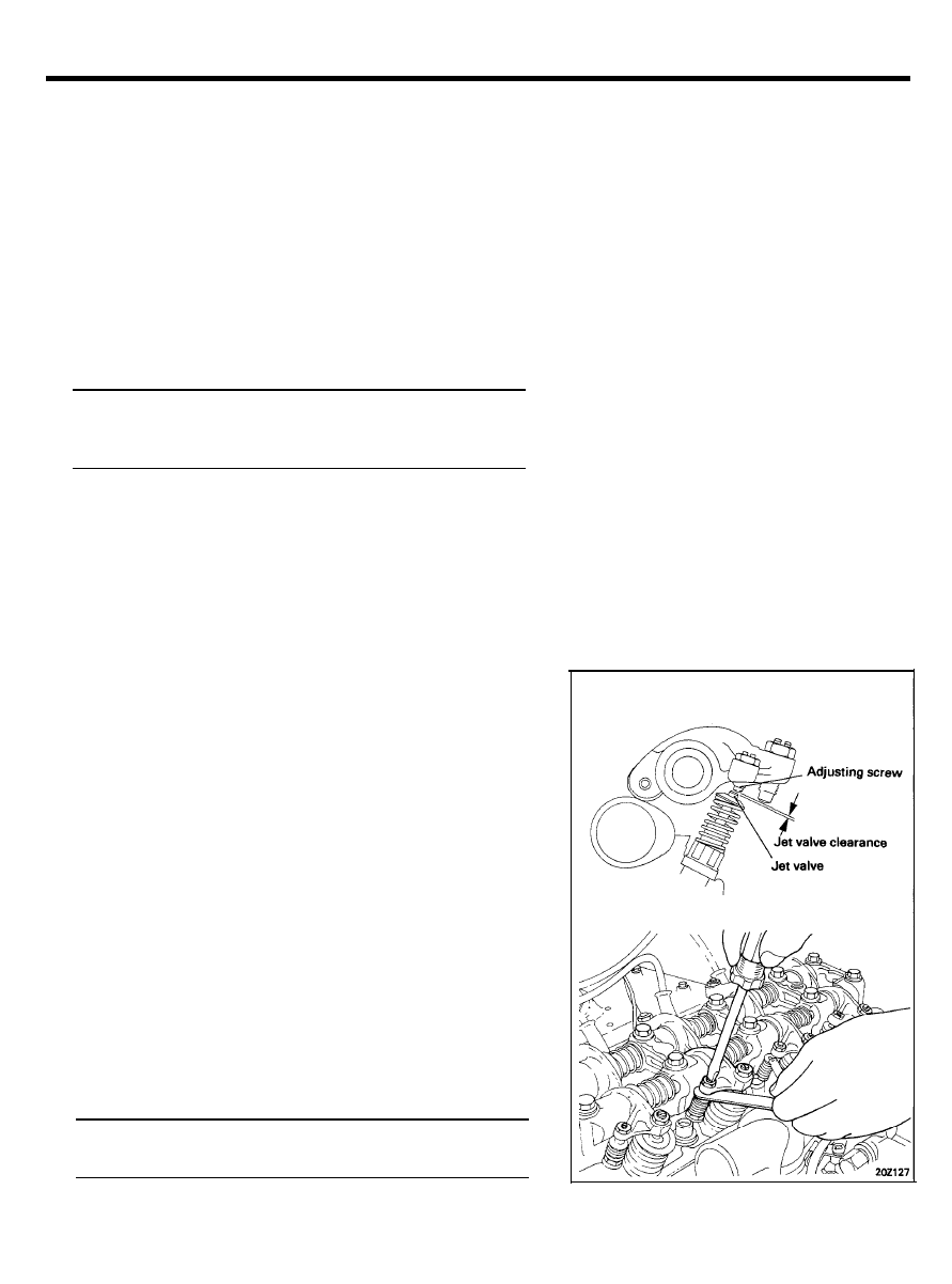
Turn the adjusting screw for the jet valve counterclockwise
and insert a 0.25 mm (0.010 in.) feeler gauge between the
jet valve stem and adjusting screw.
Jet valve clearance (hot engine)
[Standard value]. . . . . . . . . . . . . . . . . . . 0.25 mm (0.010 in.)
2 0 - 5 2
JET VALVE (FBC)
6.
Tighten the adjusting screw until it touches the feeler gauge.
Since the jet valve spring is weak in tensile strength, use
special care not to force the jet valve in. Be careful
particularly when the adjusting screw is hard to turn.
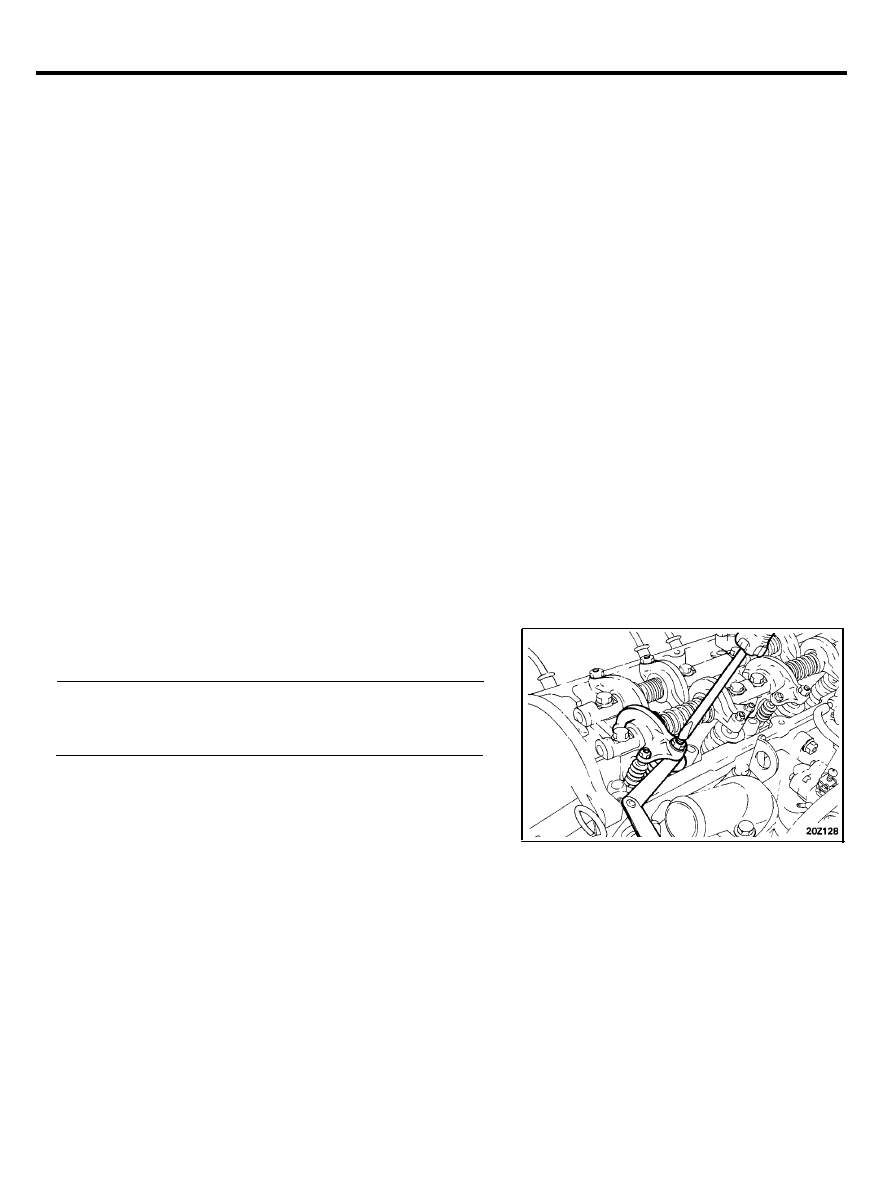
7. Tighten the lock nut securely while holding the rocker arm
adjusting screw with a screwdriver to prevent it from turning.
8.
Make sure that a 0.25 mm (0.010 in.) feeler gauge can be
easily inserted.
9. Adjust the intake valve clearance.
10. Check for idle CO and R.P.M. and adjust if necessary.
INTAKE AND EXHAUST VALVE CLEARANCE
ADJUSTMENT PROCEDURE
CAUTIONS
1) Adjust the jet valve clearance before adjusting intake valve
clearance.
2) The valve clearance should be adjusted after additional
tightening of the cylinder head bolts.
1. Warm up the engine until the temperature of the coolant
rises to 80 to 95°C (176 to 205°F).
2.
With the piston positioned at TDC on the compression stroke,
adjust as follows:
3. Loosen the lock nut.
4. Adjust the valve clearance by turning the adjusting screw
while measuring the clearance with a feeler gauge.
Valve clearance (hot engine) [Standard value]
Intake . . . . . . . . . . . . . . . . . . . . . . . . . . . . . 0.15 mm (0.006 in.)
Exhaust. . . . . . . . . . . . . . . . . . . . . . . . . . 0.25 mm (0.010 in.)
5. Tighten the lock nut securely while holding the rocker arm
adjusting screw with a screwdriver to prevent it from turning.
6. Check for idle CO, HC and R.P.M. and adjust if necessary.
2 0 - 5 3
FRONT CASE, OIL PUMP
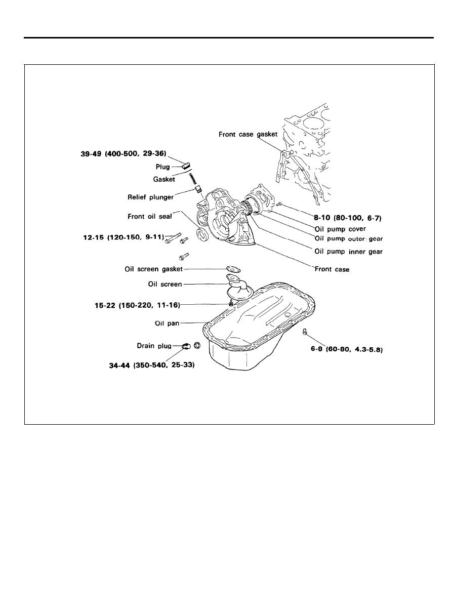
FRONT CASE, OIL PUMP
COMPONENTS
TORQUE : Nm (kg.cm, lb.ft)
REMOVAL
1. Remove the timing belt. Refer to “Timing Belt”.
2. Remove all the oil pan bolts.
3. Remove the oil pan.
4. Remove the oil screen.
5. Remove the front case assembly.
2 0 - 5 4
FRONT CASE, OIL PUMP
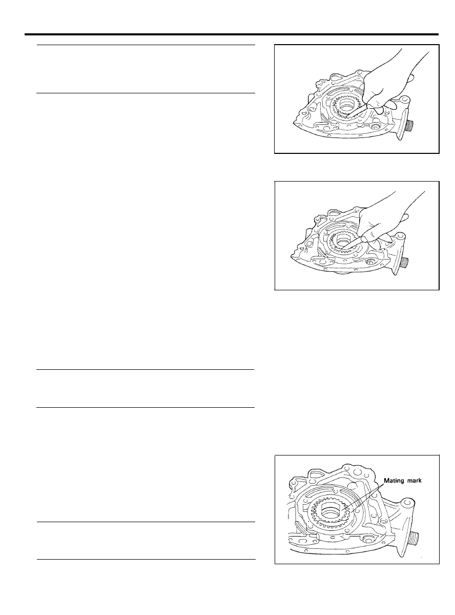
6.
7.
8.
Remove the oil pump cover.
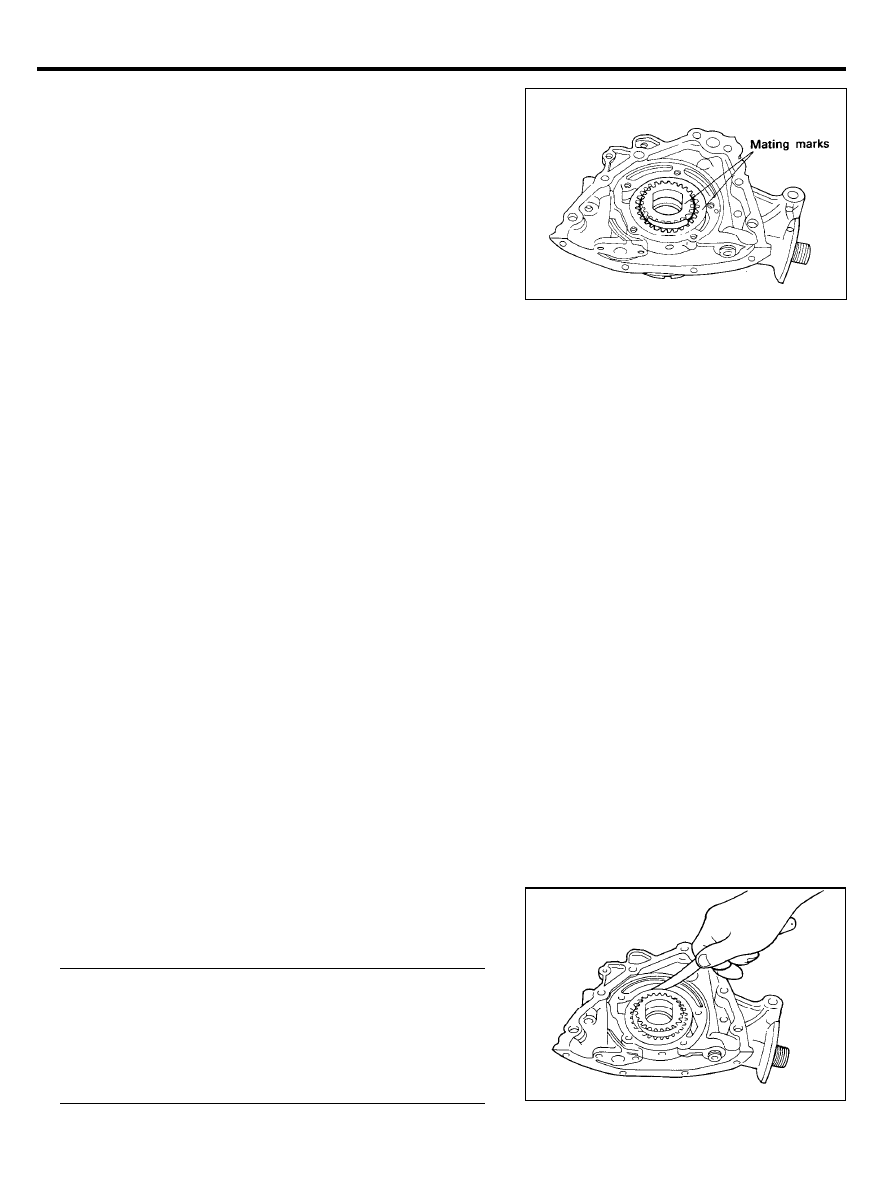
Remove the inner and outer gears from the front case. The
mating marks on the inner and outer gears indicate the
direction of installation. Make sure that the inner and outer
gears are installed as shown.
Remove the plug and remove the relief spring and relief
valve.
INSPECTION
Front Case
1. Check the front case for cracks or damage. Replace as
necessary.
2.
Check the front oil seal for worn or damaged lips. Replace
if defective.
Oil Pan and Oil Screen
1. Check the oil pan for failure, damage or cracks.
Replace if defective.
2. Check the oil screen for failure, damage and cracks and
replace if defective.
Front Case and Oil Pump Cover
Worn (especially stepped) or damaged surfaces contacting gears.
Oil Pump Gears
1. Worn or damaged gear tooth surfaces.
2. Clearance between outer gear and front case.
Outer gear
Clearance between outer circumference and front case
0.1-0.2 mm (0.0039-0.0079 in.)
Clearance between addendum and crescent . . . . . . . . . . .
0.22-0.34 mm (0.0087-0.0134 in.)
End play . . . . . . . . . . 0.04-0.10 mm (0.0016-0.0039 in.)
2 0 - 5 5
FRONT CASE, OIL PUMP
Inner gear
Clearance between addendum and crescent . . . . . . . . . . .
0.21-0.32 mm (0.0083-0.0126 in.)
End play . . . . . . . . . . 0.04-0.10 mm (0.0016-0.0039 in.)
3.
Check the clearance between the outer gear addendum and
crescent.
4.
Check the clearance between the inner gear addendum and
crescent.
Relief Valve and Spring
1. Check sliding condition of the relief valve inserted in the
front case.
2. Inspect for distorted or broken relief valve spring.
[Standard value]
Free height . . . . . . . . . . . . . . . . . . . . . . .46.6 mm (1.835 in.)
L o a d . . . . . . . . . . . . . . 6.1 kg/40.1 mm (13.4 lb/1.579 in.)
lNSTALLATlQN
Oil Pump
1.
Install the outer and inner gears into the front case. Make
sure that the inner and outer gears are installed in the same
direction as shown.
2. Install the oil pump cover and tighten the bolts to the
specified torque. After the bolts have been tightened, check
to ensure that the gear turns smoothly.
Tightening torque
Oil pump cover bolt . . . . . . . . . . . . . . . . . . . . . . . . . . . . . . . . . .
8-10 Nm (80-100 kg.cm, 6-7 lb.ft)
2 0 - 5 6

FRONT CASE, OIL PUMP
3. Install the relief valve and spring. Tighten the plug to the
specified torque. Apply engine oil to the relief valve.
Tightening torque
Relief valve plug . . . . . . . . . . . . . . . . . . . . . . . . . . . . . . . . . . . . .
39-49 Nm (400-500 kg.cm, 29-36 lb.ft)
Front Case
Install the front case assembly with a new gasket, and tighten
the bolts to the specified torque.
Body length (A) . . . . . . . . . . . . . . . . . . . . . . . . . . . 30 mm (1.18 in.)
(B) . . . . . . . . . . . . . . . . . . . . . . . . . . . 20 mm (0.79 in.)
(C) . . . . . . . . . . . . . . . . . . . . . . . . . . . 60 mm (2.36 in.)
Tightening torque.. . . . . . . . . . . . . . . . . . . . . . . . . . . . . . . . . . . . . . . . .
12-15 Nm (120-150 kg.cm, 8.7-11 lb.ft)
Oil Seal
1. Inspect for worn, distorted or damaged lips.
2. Check for elongated spring ring.
3. Install Special Tool, Crankshaft Front Oil Seal Guide
(09214-21100), to the front end of the crankshaft. Apply
engine oil to the outer surface of the oil seal guide, and
install the new oil seal along the guide by hand, until it
toughes front case. Always use a new oil seal when
reassembling.
4. Use Special Tool, Crankshaft Front Oil Seal Installer
(09214-21000), to install the oil seal.
5. Install the crankshaft sprocket, timing belt and crankshaft
pulley. Refer to “Timing Belt”.
6. Install the oil screen.
7. Clean both gasket surfaces of the oil pan and the cylinder
block.
FRONT CASE, OIL PUMP
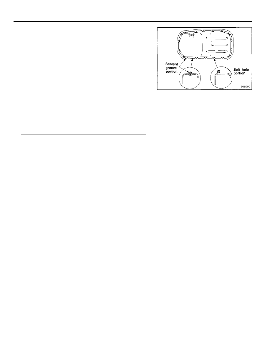
8.
Apply sealant into the groove of the oil pan flange as shown.
CAUTION
1) Apply sealant approx. 4 mm (0.16 in.) in thickness.
2) After application of sealant, do not exceed 15 minutes
before installing the oil pan.
9. Install the oil pan and tighten the bolts to the specified
torque.
Tightening torque
Oil pan bolt. . . . . . . 6-8 Nm (60-80 kg.cm, 4-6 lb.ft)
2 0 - 5 8
PISTON AND CONNECTING ROD
PISTON AND CONNECTING ROD
COMPONENTS
TOROUE : Nm (kg.cm, lb.ft)
REMOVAL
1. Remove the cylinder head assembly. Refer to “Cylinder
l-lead”.
NOTE
Mark the connecting rods and caps before disassembly to
avoid an accidental mix up during reassembly.
2. Remove the oil pan and the oil screen.
3.
Remove the connecting rod cap and withdraw the piston and
connecting rod assembly from the cylinder. Keep the
connecting rod bearings in order by cylinder number.
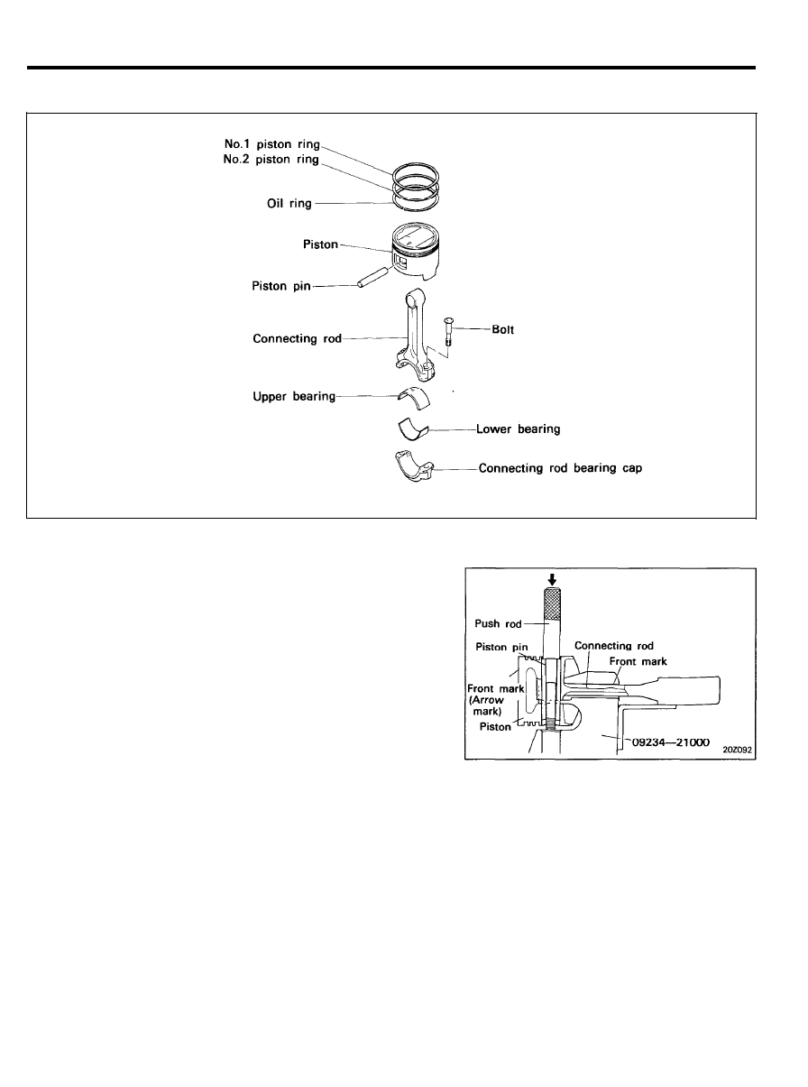
4.
Using Special Tool, Piston Pin Setting Tool (09234-21000),
disassemble the piston from the connecting rod as follows:
1) Remove piston rings.
2)
Make certain that the front mark on the top of the piston
is facing upward when the assembly is set in the press.
3) Press the piston pin out.
2 0 - 5 9

PISTON AND CONNECTING ROD
INSPECTION
Piston and Piston Pin
1. Check each piston for scuffing, scoring, wear, and other
defects.
Replace any piston that is defective.
2.
Check each piston ring for breakage, damage, and abnormal
wear. Replace the defective rings. When the piston requires
replacement, its rings also should be replaced.
3.
Check the piston pin fit in the piston pin hole. Replace any
piston and pin assembly that is defective.
The piston pin must push into the pin hole by hand at room
temperature.
Piston Rings
1. Measure the piston ring side clearance. If the measured
value exceeds the service limit, insert a new ring in a ring
groove to measure the side clearance. If the clearance still
exceeds the service limit, replace the piston and rings
together. If it is less than the service limit, replace the piston
rings only.
Piston ring side clearance
No.1 . . . . . . . . . . . . .0.03-0.07 mm (0.0012-0.0028 in.)
No.2 . . . . . . . . . . . . .0.02-0.06 mm (0.0008-0.0024 in.)
[Limit]
No.1 . . . . . . . . . . . . . . . . . . . . . . . . . . . . . . . 0.1 mm (0.004 in.)
No.2 . . . . . . . . . . . . . . . . . . . . . . . . . . . . . . . 0.1 mm (0.004 in.)
2.
To measure the piston ring end gap, insert a piston ring into
the cylinder bore. Correctly position the ring into the cylinder
by gently pushing it down with a piston. Remove the piston
and measure the end gap with a feeler gauge. If the gap is
not within the service limit, replace the piston ring.
Piston ring end gap No.1 and No.2
[Standard dimension] . . . . . . . . . . . . . . . . . . . . . . . . . . . . . . . . .
0.2-0.35 mm (0.008-0.014 in.)
[Limit]. . . . . . . . . . . . . . . . . . . . . . . . . . . . . . . 1 mm (0.039 in.)
Oil ring side rail end gap
[Standard dimension] . . 0.2-0.7 mm (0.008-0.030 in.)
[Limit]. . . . . . . . . . . . . . . . . . . . . . . . . . . . . . .1 mm (0.039 in.)
When replacing the ring only, without correcting the cylinder
bore, check the end gap with the ring positioned at the
bottom of the ring travel.
2 0 - 6 0
PISTON AND CONNECTING ROD
When replacing a ring, be sure to use a ring of the same
size.
Piston ring service size and mark
STD . . . . . . . . . . . . . . . . . . . . . . . . . . . . . . . . . . . . . . . . . . . .
None
0.25 mm (0.010 in.) O.S . . . . . . . . . . . . . . . . . . . . . . . . . . . 25
0.50 mm (0.020 in.) O.S . . . . . . . . . . . . . . . . . . . . . . . . . . 50
0.75 mm (0.030 in.) O.S . . . . . . . . . . . . . . . . . . . . . . . . . . 75
1.00 mm (0.039 in.) O.S . . . . . . . . . . . . . . . . . . . . . . . . 100
NOTE
The mark can be found on the upper side of the ring next
to the end.
Connecting Rods
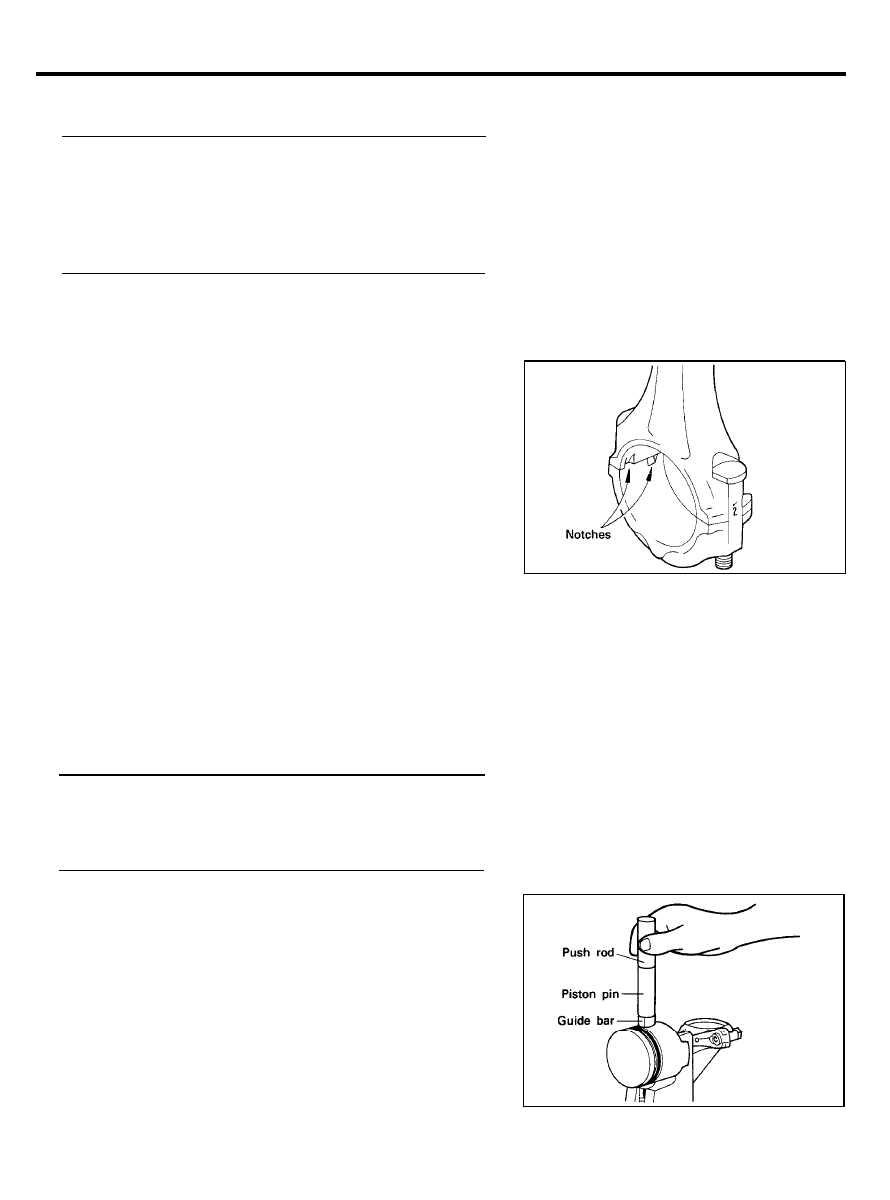
1. When reinstalling, make sure that cylinder numbers put on
the connecting rod and cap at disassembly match.
When a new connecting rod is installed, make sure that the
notches for holding the bearing in place are on the same
side.
2.
3.
Replace the connecting rod if it is damaged on the thrust
faces at either end. Also if step wear or a severely rough
surface of the inside diameter of the small end is apparent,
the rod must be replaced as well.
Using a connecting rod aligning tool, check the rod for bend
and twist. If the measured value is close to the repair limit,
correct the rod by a press. Any connecting rod that has been
severely bent or distorted should be replaced.
Allowable bend of connecting rod.. . . . . . . . . . . . . . . . . . . . . .
0.05 mm/100 mm (0.0020 in./3.94 in.) or less
Allowable twist of connecting rod.. . . . . . . . . . . . . . . . . . . . . .
0.1 mm/100 mm (0.0039 in./3.94 in.) or less
INSTALLATION
1.
Using Special Tool, Piston Pin Setting Tool (09234-21000),
assemble the piston to the connecting rod by the following
procedure.
1) Apply engine oil to the outer surface of the piston pin
and the small end bore of the connecting rod.
2 0 - 6 1
PISTON AND CONNECTING ROD
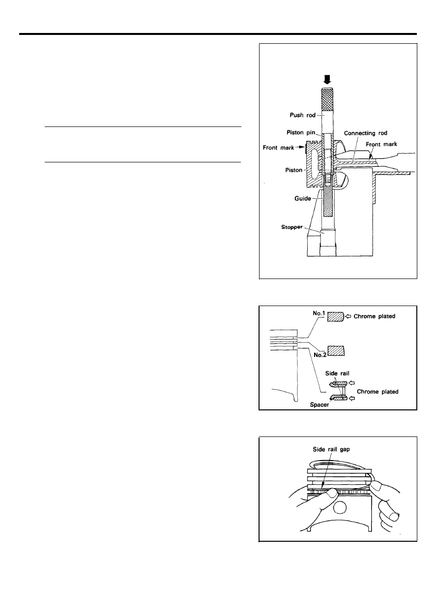
2) Set the connecting rod and piston with the front mark
facing up and insert the piston pin assembly.
Front mark
Piston side : Indented mark
Connecting rod side : Numeral, embossed.
3)
Using a install, press the piston pin into the pin hole with
the specified pressure applied through the push rod to
the pin end.
Piston pin installation pressure (At normal temperature)
[Standard value] . . . . . . . . . . . . . . . . . . . . . . . . . . . . . . . . . .
4,900-14,700 N (1,102-3,306 lb)
If more pressure than the specified pressure is required
to press the piston pin into the pin hole, complete the
following procedure.
4) Turn the push rod a half turn, and dismount the piston
connecting rod assembly from the support.
5) After pressing in the piston pin, make sure that the
connecting rod slides lightly and moves freely.
2. Install the piston rings on the piston in the following
sequence.
1) Install the 3-piece oil ring. Install the spacer expander,
upper side rail, and lower side rail in that order. When
the side rails are installed, do not expand their gaps with
the piston ring expander as with other piston rings. The
side rails might be broken if such a method is employed.
To install the side rail, first put one end of the side rail
between the piston ring groove and the spacer expander.
Hold the installed end in place. Working around the
piston, press the rest of the rail into the groove with a
finger as illustrated. Make sure that the upper side rail
is installed first and the lower side rail installed last.
CAUTION
After the 3-piece oil ring has been installed, make sure
that both the upper and lower side rails can be turned
smoothly.
Make sure that the spacer expander gap is installed more
than 45° apart from either of the side rail gaps.
2 0 - 6 2
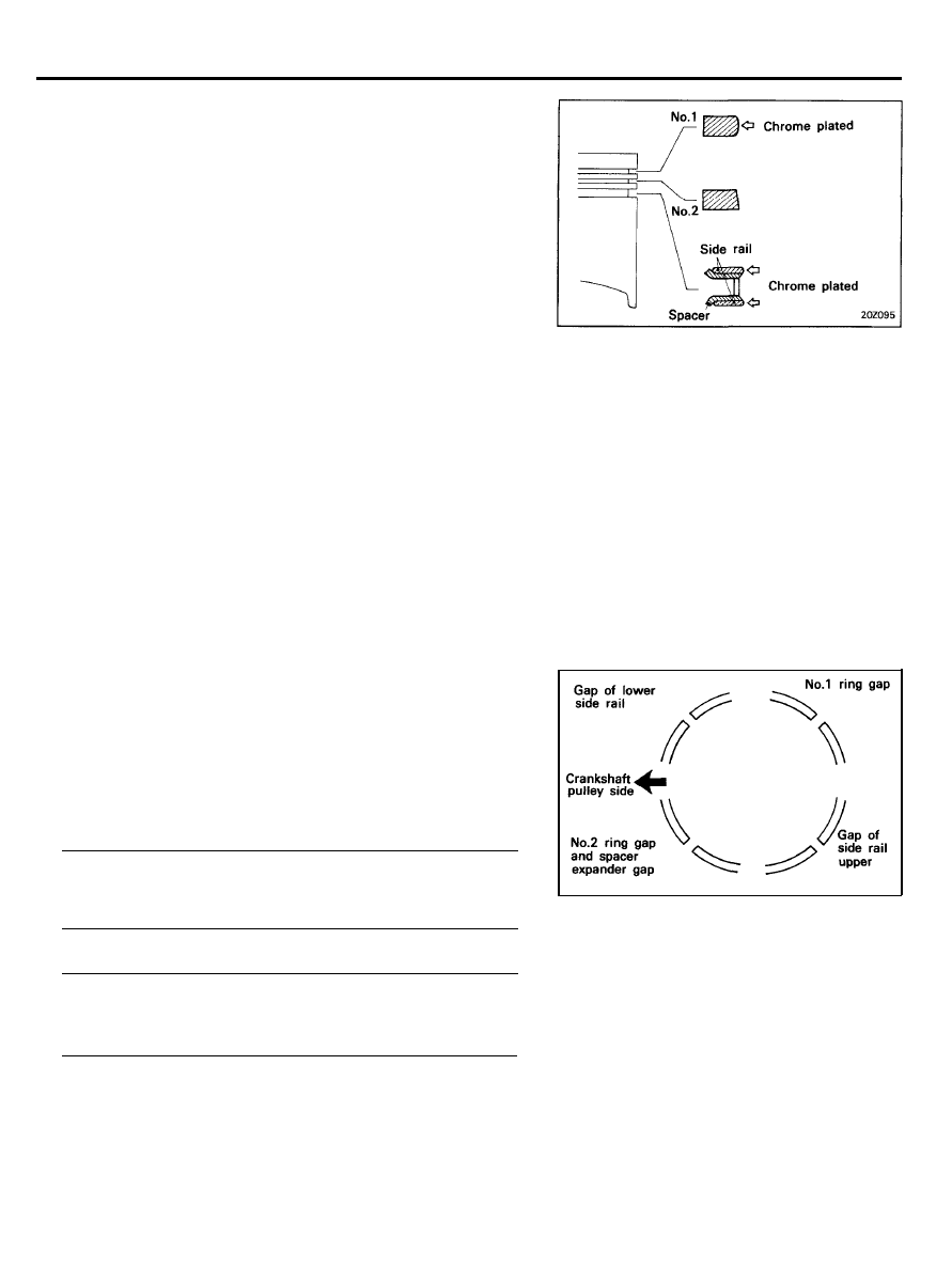
PISTON AND CONNECTING ROD
2) Install the No.2 compression ring, followed by the No.1
compression ring.
CAUTION
1) Install the piston rings in such a way that the size mark
and maker stamped on the ring surface will face the
piston top.
2) The No.1 and No.2 compression rings have the same
thickness. But these are different in cross sectional
shape. Be very careful not to reverse them.
3. Insert the piston and connecting rod assembly into the
cylinder using a piston ring compressor. The piston mating
mark must agree with the cylinder number, and with the
arrow mark on the piston head directed toward the
crankshaft pulley side of engine. It is advisable to install
protective covers over the cap bolt threads in order to avoid
causing damage to the cylinder bore and crank pin.
CAUTION
Check to ensure that the piston ring end gaps are
positioned as illustrated.
This will ensure that the piston rings are installed in such
a way that their gaps will not coincide with the piston pin
and thrust directions and that each gap will be positioned
as far apart from the neighboring gaps as possible.
Before attaching the piston ring compressor, apply engine
oil around the piston and the piston rings.
4.
Install the connecting rod cap and tighten the connecting rod
cap nuts to the specified torque. When the connecting rod
cap is installed, make sure that the match mark (cylinder No.)
stamped on the connecting rod big end and the match mark
(cylinder No.) stamped on the cap are placed on the same
side.
Tightening torque
Connecting rod cap nuts.. . . . . . . . . . . . . . . . . . . . . . . . . . . . .
31-34 Nm (320-350 kg.cm, 23-25 lb.ft)
5. Check the connecting rod big end side clearance.
Connecting rod big end side clearance
[Standard] . . . . . . . . . . . . . . . 0.1-0.25 mm (0.004-0.01 in.)
[Limit] . . . . . . . . . . . . . . . . . . . . . . . . . . . . . . . . 0.4 mm (0.016 in.)
6. Install the oil screen.
7. Install the oil pan. Refer to “Front case” section.
8. Install the cylinder head. Refer to “Cylinder Head”
2 0 - 6 3
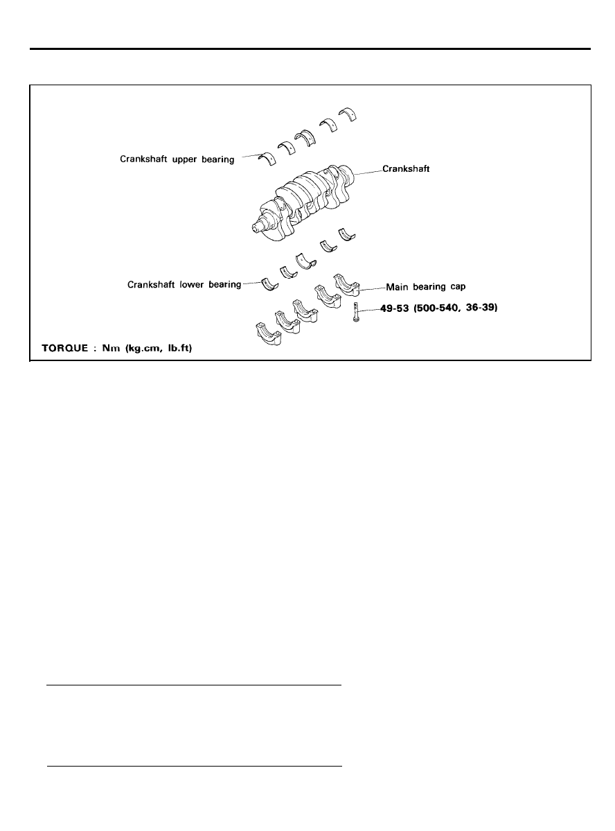
CRANKSHAFT
CRANKSHAFT
COMPONENTS
REMOVAL
1.
Remove the timing
belt, front case, flywheel, cylinder head
assembly and oil pan. For details refer to respective chapters.
2. Remove the ‘rear plate and the rear oil seal.
3. Remove the connecting rod caps.
NOTE
Mark the main bearing caps to permit reassembly in the
original position and direction.
4. Remove the main bearing caps and remove the crankshaft.
Keep the bearings in order by cap number.
INSPECTION
Crankshaft
1.
Check the crankshaft journals and pins for damage, uneven
wear and cracks. Also check oil holes for clogging. Correct
or replace any defective part.
2. Inspect out-of-roundness and taper of the crankshaft
journals and pins.
[Standard dimension]
Crankshaft journal O.D . . . . . . . . . . . . 48 mm (1.8898 in.)
Crank pin O.D . . . . . . . . . . . . . . . . . . . . 42 mm (1.6535 in.)
Crankshaft journal pin out-of-roundness and taper.. . . .
0.01 mm (0.004 in.) or less
2 0 - 6 4
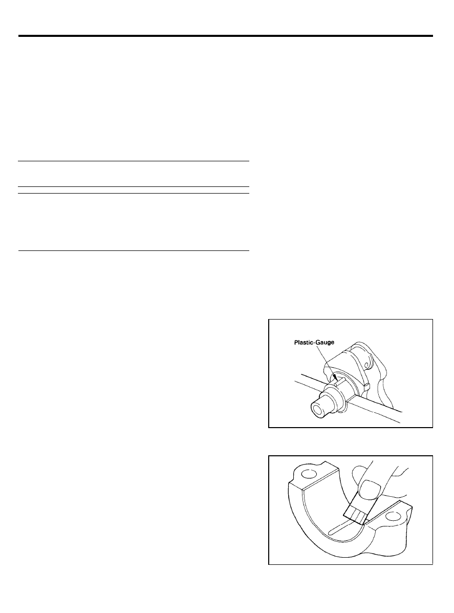
CRANKSHAFT
Main Bearings and Connecting Rod Bearings.
Visually inspect each bearing for peeling, overheating, seizure
and improper contact. Replace the defective bearings.
Oil Clearance Measurement
To check the oil clearance, measure the outside diameter of the
crankshaft journal and the crank pin and the inside diameter of
the bearing. The clearance can be obtained by calculating the
difference between the measured outside and inside diameters.
Journal oil clearance . . . . 0.02-0.07 mm (0.0008-0.0028 in.)
Pin oil clearance . . . . . . . . 0.01-0.06 mm (0.0004-0.0024 in.)
Tightening torque
Main bearing cap bolt.. . . . . . . . . . . . . . . . . . . . . . . . . . . . . . . . . . .
49-53 Nm (500-540 kg.cm, 36-39 lb.ft)
Connecting rod cap nut . . . . . . . . . . . . . . . . . . . . . . . . . . . . . . . . . .
31-34 Nm (320-350 kg.cm, 23-25 Ib.ft)
Oil Clearance Measurement (Plastigauge Method)
Plastigauge may be used to measure the clearance.
1.
Remove oil and grease and any other dirt from the bearings
and journals.
2.
Cut the plastigauge to the same length as the width of the
crankshaft journal and place it in parallel with the journal,
away from oil holes.
3. Install the bearings and caps and tighten them to the
specified torque. During this operation, do not turn the
crankshaft. Remove the caps. Measure the width of the
plastigauge at the widest part by using a scale printed on
the plastigauge package.
If the clearance exceeds the repair limit, the bearing should
be replaced or an undersize bearing be used.
When installing a new crankshaft, be sure to use standard
size bearings.
Should the standard clearance not be obtained even after
bearing replacement, the journal should be ground to a
recommended undersize, and a bearing of the same size
should be installed.
Oil Seal
Check the front and rear oil seals for damage or worn lips.
Replace any seal that is defective.
2 0 - 6 5
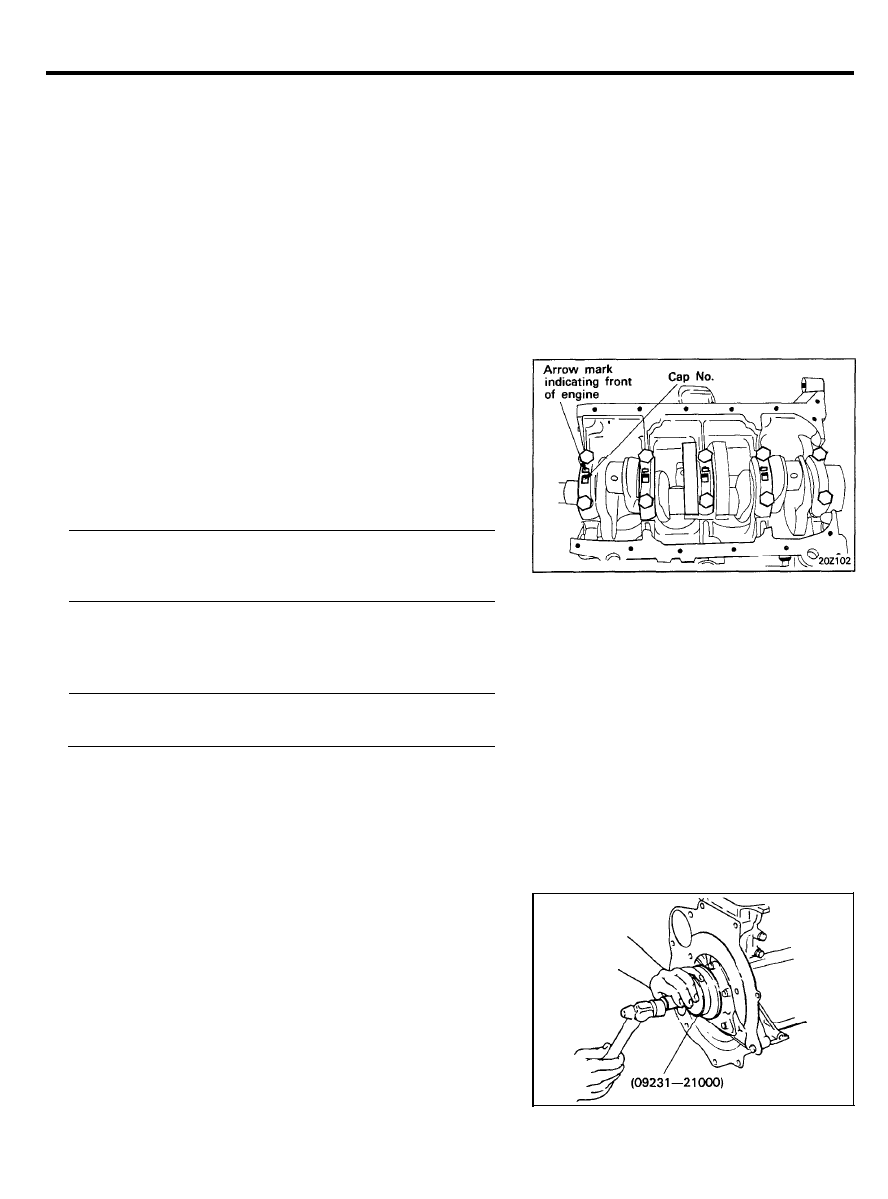
CRANKSHAFT
INSTALLATION
1.
Install the upper main bearing inserts in the cylinder block.
When reusing the main bearings, remember to install them
by referring to the location marks made at the time of
disassembly.
Oil holes in the bearings must match up with the oil holes
in the block.
2. Install the crankshaft. Apply engine oil to the journals.
3.
Install the bearing caps and tighten the bolts to the specified
torque in the following sequence: No.3, No.2, No.4, No.1 and
No.5.
Cap bolts should be tightened evenly in 2 to 3 stages before
they are tightened to the specified
torque.
The caps should be installed with the arrow mark directed
toward the crank pulley side of engine. Cap numbers must
be in order.
Tightening torque
Main bearing cap bolt . . . . . . . . . . . . . . . . . . . . . . . . . . . . . . . .
49-53 Nm (500-540 kg.cm, 36-39 Ib.ft)
4. Make certain that the crankshaft turns freely and has the
proper clearance between the center main bearing thrust
flange and the connecting rod big end bearing.
5.
6.
7.
8.
9.
Crankshaft end play . . . . . . . . . . . . . . . . . . . . . . . . . . . . . . . . . . . .
0.05-0.18 mm (0.002-0.007 in.)
Install the oil seal in the crankshaft rear oil seal case. Use
S p e c i a l T o o l , C r a n k s h a f t R e a r O i l S e a l I n s t a l l e r
(09231-21000) as shown. Press fit the oil seal all the way
in, being careful not to misalign it.
Install the rear oil seal case and gasket. Tighten the five
bolts. Apply engine oil to the oil seal lips and crankshaft at
the time of installation.
Install the rear plate and tighten the bolts.
Install the connecting rod caps. Refer to “Piston and
Connecting Rods”.
Install the flywheel, front case, oil pan and timing belt. For
further details, refer to the respective chapters.
2 0 - 6 6
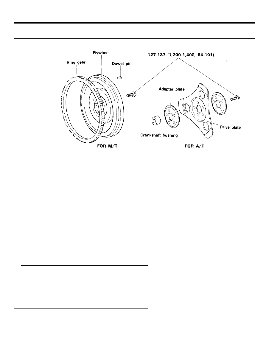
FLYWHEEL
FLYWHEEL
COMPONENTS
TORQUE : Nm (kg.cm. Ib.ft)
M/T : Manual Transaxle Vehicles
A/T : Automatic Transaxle Vehicles
REMOVAL
1. Remove the transaxle and clutch.
2. Remove the flywheel.
INSPECTlON
1.
Check the clutch disc contacting surface of the flywheel for
damage and wear. Replace the flywheel if excessively
damaged
or
worn.
2.
Check the clutch disc contacting surface of the flywheel for
run-out.
Standard value
Flywheel run-out . . . . . . . . . . . . . . . . . . . 0.1
mm (0.004 in.)
3. Check the ring gear for damage, cracks and wear, and
replace if necessary.
INSTALLATION
Install the flywheel assembly and tighten the bolts to the
specified torque.
Tightening torque
Flywheel bolt . . . . . . . . . . . . . . . . . . . . . . . . . . . . . . . . . . . . . . . . . . . . . . . . . . . . . .
127-137 Nm (1,300-1,400 kg.cm, 94-101 Ib.ft)
2 0 - 6 7
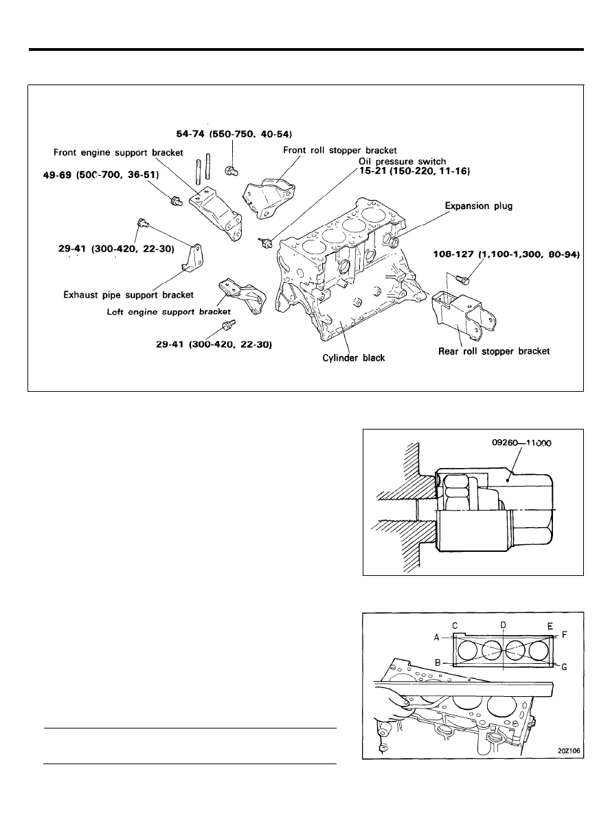
CYLINDER BLOCK
CYLINDER BLOCK
COMPONENTS
TORQUE : Nm (kg.cm. Ib.ft)
REMOVAL
1.
Remove the cylinder head, timing belt, front case, flywheel,
piston and crankshaft.
2. Using the special tool (09260-11000), remove the oil
pressure switch.
For further details, refer to the respective chapters.
INSPECTION
Cylinder Block
I. Visually check the cylinder block for scratches, rust and
corrosion. Also check for cracks or any other defects, using
a flaw detecting agent (magnafluxing). Correct or replace the
block if defective.
2.
Using a straightedge and feeler gauge, check the block top
surface for warpage. Make sure that the surface is free from
gasket chips and other foreign matter.
Standard . . . . . . . . . . . . . . . . . . . 0.05 mm (0.0020 in.) or less
Limit.. . . . . . . . . . . . . . . . . . . . . . . . . . . . . . . 0.1 mm (0.0039 in.)
2 0 - 6 8
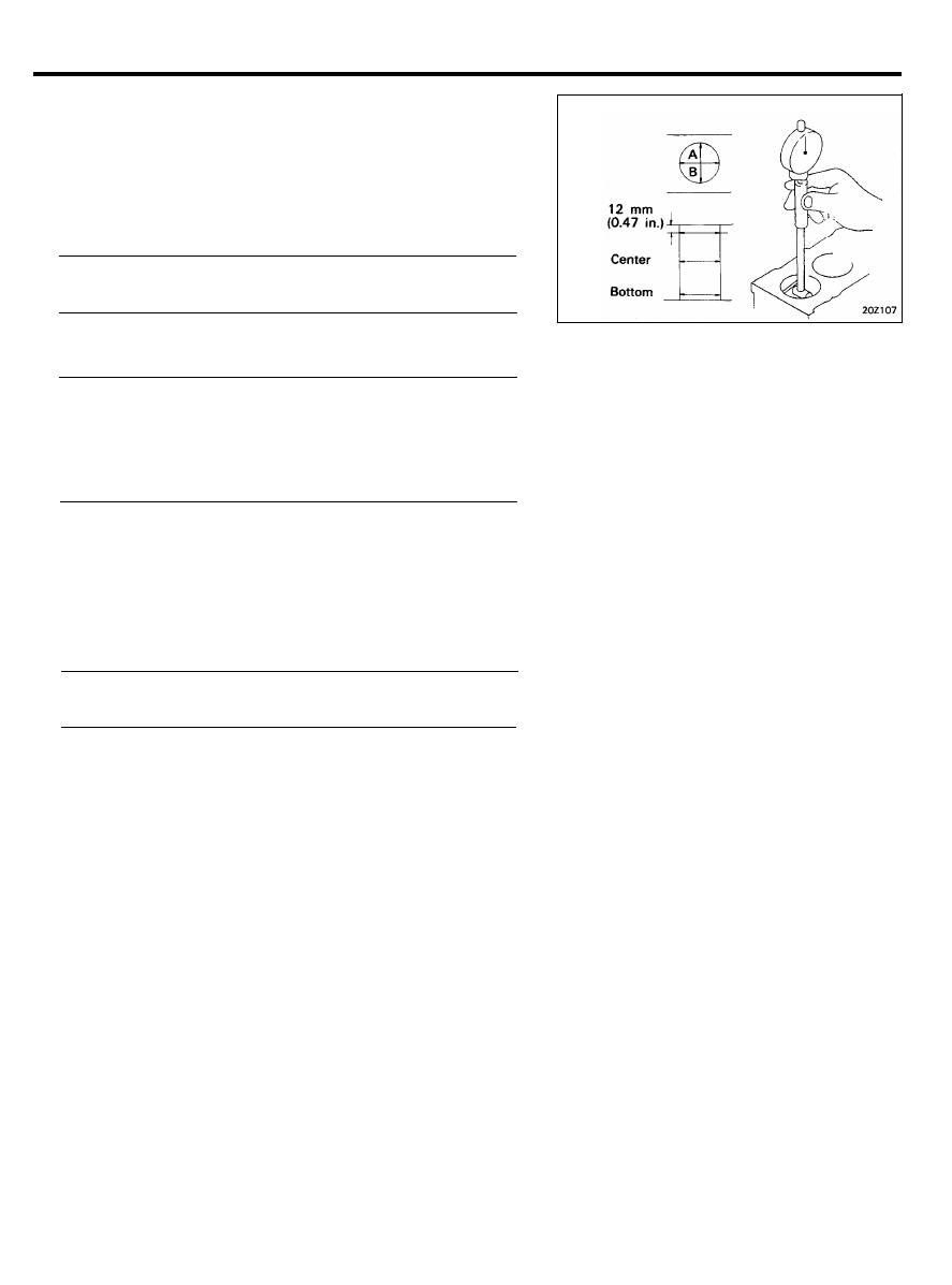
CYLINDER BLOCK
3. Measure the cylinder bore with a cylinder gauge at three
levels in the directions A and B. If the cylinder bores show
more than the specified out-of-round or taper or if the
cylinder walls are badly scuffed or scored, the cylinder block
should be rebored and honed. New oversize pistons and rings
must be fitted.
Measuring points are as shown.
Cylinder I.D.. . . . . . . . . . 75.5-75.53 mm (2.972-2.974 in.)
Cylinder I.D. taper . . . . . . . . . . 0.02 mm (0.0008 in. or less)
4. If a cylinder ridge exists, cut away with a ridge reamer.
5. Oversize pistons are available in four sizes.
Piston service size and mark mm (in.)
0.25 (0.010) O.S . . . . . . . . . . . . . . . . . . . . . . . . . . . . . . . . .
0.25
0.50 (0.020) O.S . . . . . . . . . . . . . . . . . . . . . . . . . . . . . . . . 0.50
0.75 (0.030) O.S . . . . . . . . . . . . . . . . . . . . . . . . . . . . . . . . .
0.75
1.00 (0.039) O.S . . . . . . . . . . . . . . . . . . . . . . . . . . . . . . . . .
1.00
6.
When boring the cylinder bore to oversize, keep the specified
clearance between the oversize piston and the bore, and
make sure that all pistons used are of the same oversize.
The standard measurement of the piston outside diameter is
taken at a level 12 mm (0.47 in.) above the bottom of the
piston skirt and across the thrust faces.
Piston-to-cylinder wall clearance . . . . . . . . . . . . . . . . . . . . . . . .
0.02-0.04 mm (0.0008-0.0016 in.)
INSTALLATION
Install the following parts by referring to the respective chapters.
(a) Crankshaft
(b) Flywheel
(c) Piston
(d) Cylinder head
(e) Timing belt
(f) Front case
2 0 - 6 9
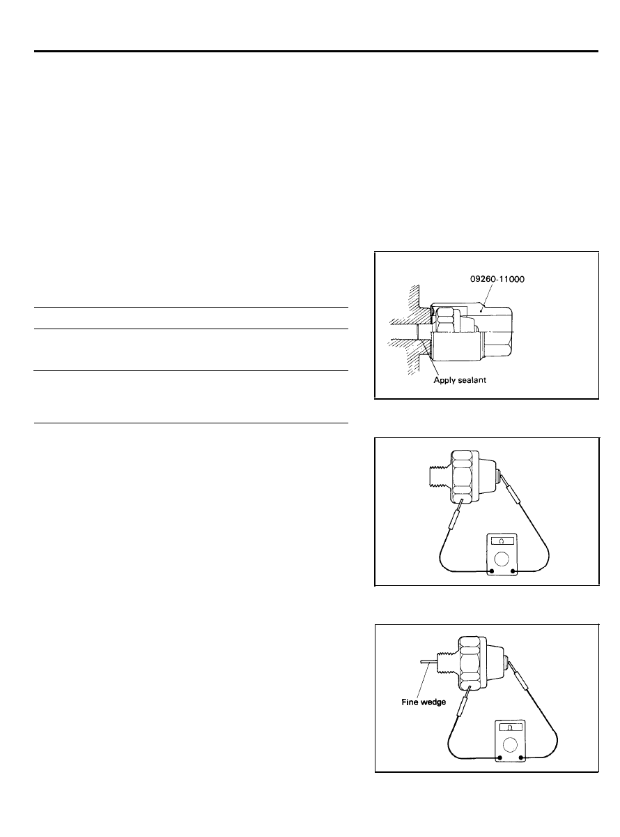
OIL PRESSURE SWITCH
OIL PRESSURE SWITCH
The oil pressure switch is located at the center of the right-hand
side of the engine. If the oil pressure in the lubricating system
has dropped below 28 kPa (4 psi) during normal operation, the
oil pressure warning light will come on. The hexagonal portion
of this switch is 26 mm (1.024 in.) wide across the flats.
REMOVAL AND INSTALLATION
Using the special tool (09260-11000), install the oil pressure
switch after applying sealant to the threaded area.
Sealant.. . . . . . . . . . . . . . . . . . . . . . Threebond 1104 or equivalent
NOTE
Do not over torque the oil pressure switch.
Tightening torque
Oil pressure switch . . . . . . . . . . . . . . . . . . . . . . . . . . . . . . . . . . . . . .
15-21 Nm (150-220 kg.cm, 11-15 Ib.ft)
INSPECTION
1.
Check the continuity between the terminal and the body with
an ohmmeter.
If there is continuity, replace the oil pressure switch.
2. Check the continuity between the terminal and the body
when the fine wedge is pushed. If there is continuity even
when the fine wedge is pushed, replace it.
3.
Or, if there is no continuity when a 50 kPa (70 psi) vacuum
is applied through the oil hole, the switch is operating
properly. Check to see that air doesn’t leak. If air leaks, the
diaphragm is broken. Replace the switch.
2 0 - 7 0
Wyszukiwarka
Podobne podstrony:
więcej podobnych podstron