
Easy-Drive
for Configuring a AC &DC Version 2 Drive


GEH-6412A Easy-Drive for AV-300i Version 2 Drive
Contents
••••
i
Contents
Chapter 1 Overview
1-1
Introduction.............................................................................................................................1-1
Before Beginning....................................................................................................................1-1
How To Use This Manual ........................................................................................1-1
Conventions..............................................................................................................1-2
Chapter 2 Installation
2-1
Introduction.............................................................................................................................2-1
Computer Requirements .........................................................................................................2-1
Installing Easy-Drive ..............................................................................................................2-2
Registration License Agreement...............................................................................2-2
Destination Directory ...............................................................................................2-3
Product Selection......................................................................................................2-3
Uninstall Products ....................................................................................................2-4
Chapter 3 Using the Easy-Drive
3-1
Introduction.............................................................................................................................3-1
Upgrading from Previous Releases.........................................................................................3-2
Maintaining Multiple Releases of Easy-Drive..........................................................3-2
Starting the Easy-Drive...........................................................................................................3-3
Work Area ................................................................................................................3-3
Accessing Online Help ...........................................................................................................3-5
Privileges and Passwords........................................................................................................3-5
Privilege Levels ........................................................................................................3-5
Change Password or Default Password Directory ....................................................3-7
Easy-Drive Options.................................................................................................................3-8
General .....................................................................................................................3-8
Startup ......................................................................................................................3-9
Block Diagram........................................................................................................3-10
Trend Recorder.......................................................................................................3-11
AC&DC Version 2 Drive .......................................................................................3-12
Connecting the Easy-Drive ...................................................................................................3-13
Chapter 4 Configuring an AC & DC Version 2 Drive
4-1
Introduction.............................................................................................................................4-1
Creating an AC & DC Version 2 Drive ..................................................................................4-1
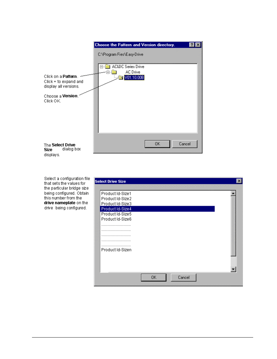
Pattern and Version ..................................................................................................4-2
Drive Size .................................................................................................................4-3
Enter User Identification ..........................................................................................4-4
Configuring the Drive.............................................................................................................4-5
Modifying Drive Properties......................................................................................4-5
Validating the Drive .................................................................................................4-6
Entering Job-Specific Information ...........................................................................4-6
Working with Files and Menus...............................................................................................4-7
File Types .................................................................................................................4-7
Opening and Closing Files .......................................................................................4-8

ii
••••
Contents
GEH-6412A TEasy-Drivefor AC & DC Version 2 Drive
Saving Files ..............................................................................................................4-8
Upgrading a Configuration.......................................................................................4-8
Exporting Configuration Files ................................................................................4-10
Exporting and Opening Project Files......................................................................4-10
Menu Commands....................................................................................................4-11
Concepts ...............................................................................................................................4-16
Configuration........................................................................................................................4-17
Parameters ..............................................................................................................4-17
Easy-Drive/Drive Communications........................................................................4-18
Connecting to an AC & DC Version 2 Drive .........................................................4-19
Uploading Parameter Values ..................................................................................4-19
Downloading Parameter Values .............................................................................4-20
Downloading Firmware..........................................................................................4-20
Block Diagram......................................................................................................................4-21
Links to Other Pages ..............................................................................................4-21
Modify Parameters from Diagram..........................................................................4-22
Parameter Jumpers..................................................................................................4-22
Live Data Display...................................................................................................4-22
Drag-and-Drop Variables .......................................................................................4-23
Printing Diagrams...................................................................................................4-23
Programmable Block Area....................................................................................................4-24
Block Library .........................................................................................................4-24
Inserting Blocks......................................................................................................4-24
Modifying Block Properties ...................................................................................4-26
Connecting Pins from Block Flow View................................................................4-26
Execution Order .....................................................................................................4-27
Uploading and Downloading Block Area...............................................................4-28
Printing Block Area................................................................................................4-29
Drive Controls ......................................................................................................................4-29
Wizards.................................................................................................................................4-29
Choose a Wizard ....................................................................................................4-30
Fault Display.........................................................................................................................4-31
Active Fault ............................................................................................................4-31
Fault History...........................................................................................................4-32
Self-Tune ..............................................................................................................................4-32
Self-tune the Current Regulator..............................................................................4-32
Self-tune the Speed Regulator ................................................................................4-35
Using the Finder ...................................................................................................................4-36
Finder Window.......................................................................................................4-36
ISBus Configuration .............................................................................................................4-37
Adding an ISBus to Configuration .........................................................................4-38
Editing an ISBus.....................................................................................................4-38
ISBus Pages ............................................................................................................4-39
Setting References from ISBus to Drive ................................................................4-39
Feedbacks from Drive to the ISBus........................................................................4-40
AC &DC Version 2 Capture Buffer......................................................................................4-41
Capturing Data Block .............................................................................................4-41
Configuring the Capture Block...............................................................................4-41

GEH-6412A Easy-Drive for Ac & DC Version 2 Drive
Chapter 1 Overview
••••
G-1
Chapter 1 Overview
Introduction
This manual describes the Easy-Drive, which is personal computer (PC)-based
software used to configure and maintain the drives. The Easy-Drive is a Windows
®
-
based application, which runs on a Pentium
®
166 or higher PC.
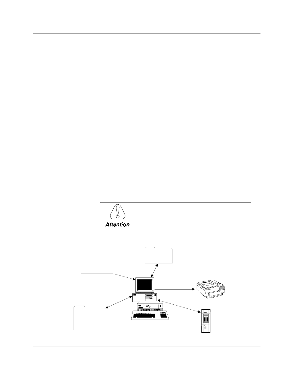
Primary functions of the Easy-Drive include:
The Easy-Drive software
configures various control
equipment. Therefore, each
product package can consist of
the Easy-Drive, product files for
the drive, and Trend Recorder.
•
Configuration wizards
•
Live data block flow diagrams
•
Online Help files
•
Input/Output (I/O) configuration and
monitoring
•
Signal management and signal trending
•
Generate reports
•
Programmable Block Area
Before Beginning
Windows-based screen
borders may vary in
appearance.
This manual describes the features of the Easy-Drive and presents step-by-step
procedures for using the software applications provided. It presumes that the user
has already installed Windows. This manual also assumes that the user possesses at
least a medium-level knowledge of Windows. Hardware requirements and
instructions for installing the products are provided in Chapter 2.
How To Use This Manual
This manual provides information on installing the Easy-Drive and other products
used to configure control equipment. It also describes other features provided in the
Easy-Drive software package. This manual is organized as follows:
Chapter 1 Overview. This chapter defines functions of the Easy-Drive, contents of
this manual, and the conventions used.
Chapter 2 Installation. This chapter describes the PC and installation requirements
for the AC & DC Version 2 drives.

G-2
••••
Chapter 1 Overview
Esay-Drive for AC & DC Version 2 Drive
Chapter 3 Using the Easy-Drive. This chapter provides basic startup procedures
and features for using the Easy-Drive to configure a product.
Chapter 4 Configuring an AC & DC Version 2 Drives. This chapter describes
how to use the Easy-Drive to configure a drive.
Glossary. The Glossary provides definitions of configuration terms and Easy-Drive
concepts.
Refer to the Table of Contents for the organization of these chapters.
Conventions
The following conventional terms, text formats, and symbols are used throughout
this documentation for the Easy-Drive.
Convention
Meaning
Bold
Indicates that the word is being defined.
Arial Bold
Indicates the menu, actual command or option that is chosen
from a menu, a button, or title of a dialog box.
Italic
Indicates a word used as a word or a letter used as a letter. For
example, the display should now read SDB has stopped. Italic
also indicates new terms, margin notes, and the titles of figures,
chapters, and other books in the Easy-Drive package.
UPPERCASE
Indicates a directory, filename, or block name. Lowercase letters
can be used when typing names in a dialog box or at the
command prompt, unless otherwise indicated for a specific
application or utility.
Monospace
Represents examples of screen text or words and characters that
are typed in a text box or at the command prompt.
!
Indicates a procedure.
"
Indicates a procedure with only one step.
•
Indicates a list of related information, not procedural steps.
The following list presents some basic guidelines for working with menus:
When a menu is displayed, press the up/down arrow keys to highlight a command
name. Then press Enter to choose the menu command. The menu can also be
selected by clicking with a cursor-positioning device (CPD), such as a mouse.
When a command ends in an ellipsis (…), the application displays a dialog box that
asks the user to supply more information.
If a command turns a feature on and off, a checkmark (#) is displayed by the
command name when the feature is on.
When a command ends with an arrow ( ), the menu cascades to display more
command names.
If a command name is grayed out, it indicates that the command does not apply to
the current situation or there is another selection or action before choosing the
command.

GEH-6412A Easy-Drive for Ac & DC Version 2 Drive
Chapter 2 Installation
••••
G-3
Related Publications
For additional information, refer to the drives' instruction book or contact the nearest
sales office.
Chapter 2 Installation
Introduction
This chapter describes the product installation requirements. The contents of this CD
depend on the products that are ordered. Available products display in the Product
Selection dialog box (see the section, Product Selection).
Computer Requirements
The minimum PC requirements are determined by the selected product combination
and the topology configuration of the PC(s). The minimum requirements to use the
Easy-Drive products are as follows:
•
100 MHz processor (Pentium 166 or higher recommended)
A cursor-positioning device is
highly recommended.
•
Microsoft
®
Windows
®
95 or Windows NT
®
4.0
•
VGA display (640 x 480 x 16 color or gray
scale)
•
16 MB RAM in Windows 95 (32 MB recommended) or 24 MB RAM in
Windows NT (32 MB recommended)
•
Serial port for direct connection to a drive
•
Printer (with appropriate Windows driver installed)
G-4
••••
Chapter 2 Installation
Esay-Drive for AC & DC Version 2 Drive
Installing Easy-Drive
Easy-Drive installs various products for control systems as selected in the setup
program. It is recommended that you exit all Windows programs before beginning.
You must agree to the standard Software License Agreement for these products.
A default destination directory is set for all products selected. This directory can be
modified, but only during the first installation. Setup installs the required
components and checks available disk space before copying files. You can also
choose to cancel setup and exit at any time before you initiate the selected products.
! To install from a CD
Install the desired products
from CD, following the
directions on the screen.
Then, install each product
file.
1. Place the Easy-Drive CD in the disk drive.
2. The Setup program executes automatically.
3. Follow the Setup instructions from the screen.
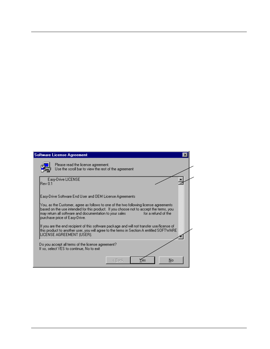
Registration License Agreement
The Software License Agreement dialog box displays during installation. The license
must be read and agreed to before installation can continue.
Please read the entire
agreement (scroll bar must
be at the bottom of the
dialog box).
Click Yes to accept the
agreement.
GEH-6412A Easy-Drive for Ac & DC Version 2 Drive
Chapter 2 Installation
••••
G-5
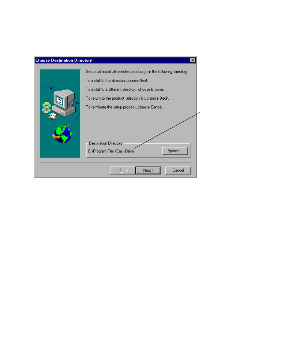
Destination Directory
The Choose Destination Directory dialog box displays during the initial installation.
All future installs and upgrades default to the first directory selected.
The destination directory for
each product is set to the
default directory C:\Program
Files\Easy-Drive. If desired
select a different directory to
load the products.
This dialog box option can
only be selected during the
initial installation of these
products. After that all future
installs and upgrades default
to the first directory selected.
Setup automatically continues to load. The product selection dialog box displays to
allow you to select desired products.
G-6
••••
Chapter 2 Installation
Esay-Drive for AC & DC Version 2 Drive
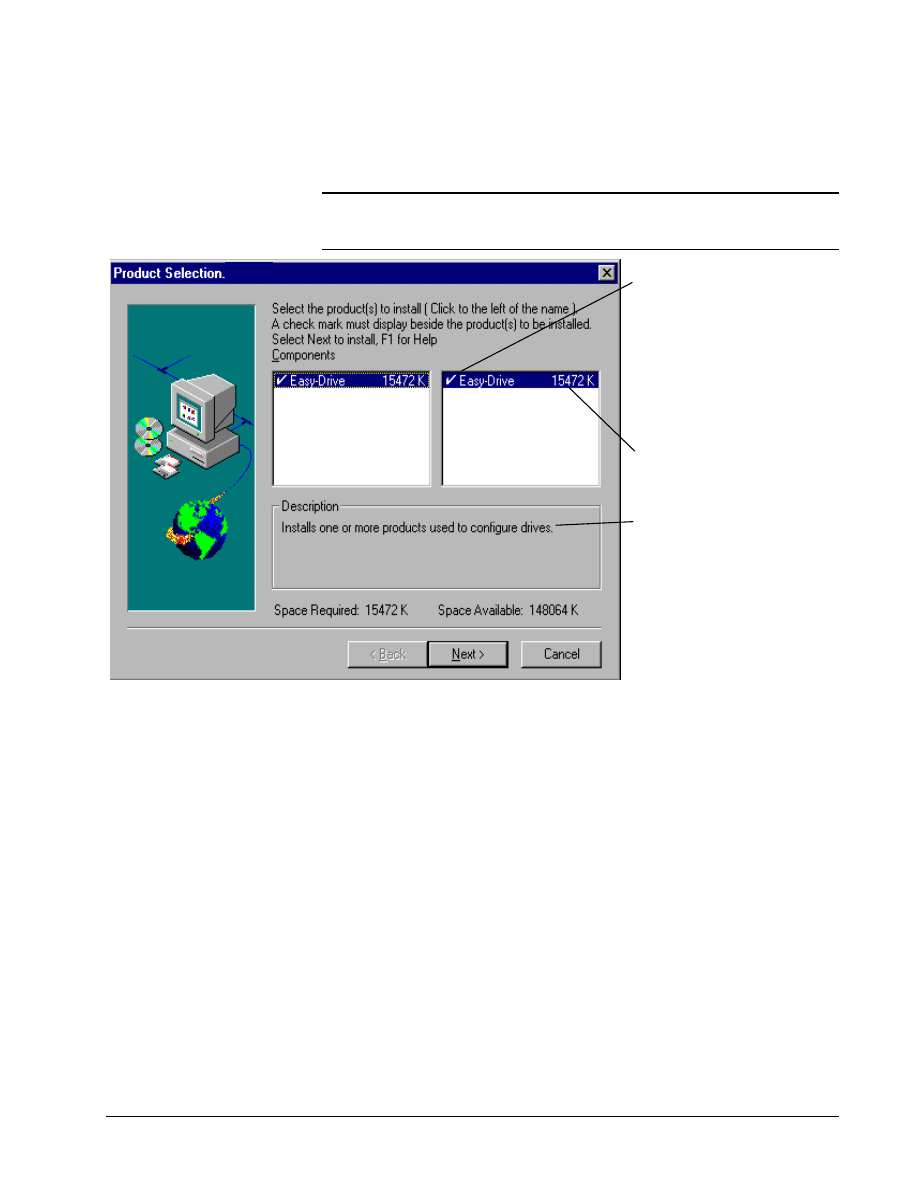
Product Selection
Tip
$
$
$
$
From the Product Selection dialog box, click on a product (highlight) to
display its description and required disk space. The total required space for all
checked items and the space available displays at the bottom of the dialog box.
You must click to the left of
product you want to install.
check mark must display
the product
Click the product name in the
column to check all
application in that group.
again to uncheck
The number beside each
indicates the amount of
required for that
A description of each
displays when it is
(highlighted).
GEH-6412A Easy-Drive for Ac & DC Version 2 Drive
Chapter 2 Installation
••••
G-7
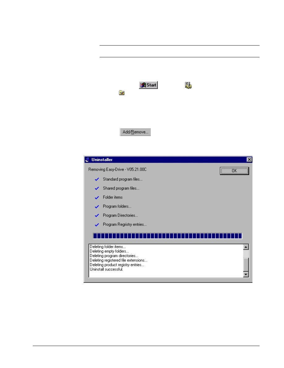
Uninstall Products
Although it is not necessary,
it is highly recommended that
you uninstall the earlier
version when upgrading to
the new release.
Note Before upgrading to Release 2, product components should be uninstalled
and then installed again using the Release 3 CD.
! To uninstall product(s)
1. Click Windows
button, select
Settings, and then
click
Control Panel.
2. From the Control Panel dialog box, double-click on Add/Remove
Programs. The Add/Remove Program Properties dialog box displays.
3. Click on the tab Install/Uninstall. A list of all installed programs displays.
4. From the list box, click on the program to uninstall.
5. Click
.
The following screen displays to show when uninstall is complete and the status of
all items deleted.

G-8
••••
Chapter 3 Using the Easy-Drive
Esay-Drive for AC & DC Version 2 Drive
Chapter 3 Using the Easy-Drive
Introduction
Settings options should be
determined before starting a
configuration.
This chapter provides basic instructions for using the Easy-Drive. It defines the
Easy-Drive menu commands, including the Options menu, which has a Settings
dialog tab for each product. Methods of communication and Easy-Drive
connections are also described.

GEH-6412A Easy-Drive for Ac & DC Version 2 Drive
Chapter 3 Using the Easy-Drive
••••
G-9
Upgrading from Previous Releases
Note To upgrade to Version 2 of the Easy-Drive, it is recommended that you first
uninstall any previous version of Easy-Drive.
Maintaining Multiple Releases of Easy-Drive
To maintain different releases of the Easy-Drive on a single system, consider the
following:
•
Multiple versions of Release 1 or higher cannot be installed on one
system. The installation directory for Release 1 or higher of the Easy-Drive is
chosen only once, the first time that product is installed.
•
There is only one set of Easy-Drive options settings for a given user
on a given computer. There are several Easy-Drive options settings that may
need to be unique to a particular release of Easy-Drive. In order to use multiple
releases, it is recommended to use different user accounts for each release.
•
Opening a Easy-Drive file from the Windows Explorer is not
recommended if multiple copies of Easy-Drive are installed. When you open
a file from the Windows Explorer, the application that starts up depends on what
is registered for that file type. Releases of Easy-Drive prior to Release 1 register
each time they execute. Release 1 or higher of Easy-Drive, however, registers
only at installation.
•
Modifying a Easy-Drive file can make the file unusable to older
releases of Easy-Drive. A warning dialog displays when the Easy-Drive opens
a file that was written by a previous release. Do not save the file if it must be
used by the previous release.
G-10
••••
Chapter 3 Using the Easy-Drive
Esay-Drive for AC & DC Version 2 Drive
Starting the Easy-Drive
To create a device, refer to
Chapter 4.
The Easy-Drive is started from the Windows NT or 95 Workstation.
! To start the Easy-Drive
1. Click Windows
button, Programs, and Easy-Drive.
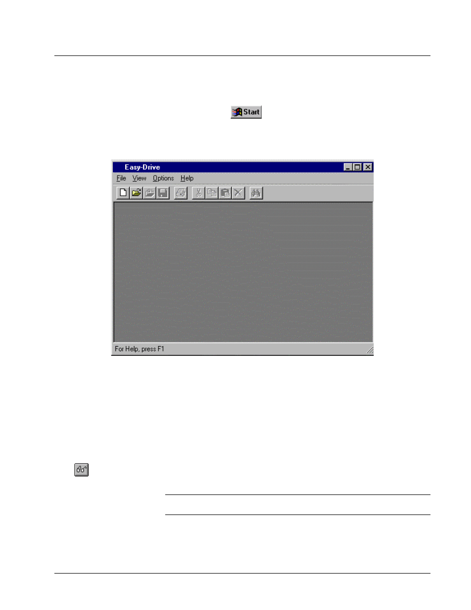
2. Click on the Easy-Drive icon. The Work Area displays. It is blank until a device
is created or opened.
Work Area
If more than one drive is open
in the Work Area, each drive
will have a window with an
Outline View and Summary
View.
A drive’s runtime action is configured using the Easy-Drive. From the File menu,
begin a New configuration or Open a previously saved configuration file. The Work
Area is the main screen and contains the following:
Outline View (left side) displays the configuration in a hierarchy, with the drive
name as the first item and other configuration items listed in levels below it.
Click
to display the
Detached Summary View.
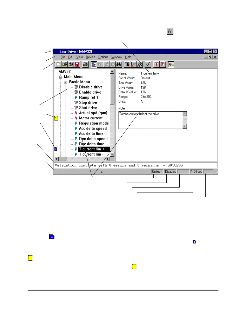
Summary View (right side) displays information for the item highlighted in the
Outline View. For example, in a drive configuration, the item Diagram displays
block diagrams, which can be configured within this view.
Detached Summary View is a separate window from the Work Area window and
displays a copy of the diagram. This window can be sized, configured, and edited.
Note The following screen represents a basic Work Area format. Menu commands,
toolbar, and Outline View items will vary with the product installed.
GEH-6412A Easy-Drive for Ac & DC Version 2 Drive
Chapter 3 Using the Easy-Drive
••••
G-11
Title bar
Menu bar
Toolbar
Outline
View
Bookmark
Notes
Log
View
From the Outline View, click on
item with a Note icon. The
displays in the Summary
Status bar
displays
toolbox
information
on the right
and drive
information
on the left
side.
Summary View display details of the item
in the Outline View. For example, the
T
currentLim+ is shown
Click to display the
Summary View. This view
details of Diagram (an overall
of the block
For Help, Press F1
Communication
Drive status
Fault
Diagram scan
Read only
Find the cause of an error by
double-clicking on the error.
Log View displays status messages for Easy-Drive activities, such as file imports,
validations, builds, or errors.
Status Bar can be toggled on and off from the View menu. When online, the left
side displays a description of various commands or notes entered by the user. The
right side displays the drive status of the current drive.
Double-click
to edit the
note.
Notes can be created for most items in the drive. Select an item, then from the Edit,
select Modify. Enter a note for the item and click OK. The Note icon displays
beside the item in the Outline View.
Bookmark items display the
icon.
Bookmark enables you to mark major items in the Outline View and then return to
them easily using the Bookmark commands in the Edit menu. The Toggle Bookmark
command turns the icon on and off. The Goto Next Bookmark command jumps to
the next item marked with the
.
G-12
••••
Chapter 3 Using the Easy-Drive
Esay-Drive for AC & DC Version 2 Drive
Accessing Online Help
To obtain Help for the dialog
box on the screen, press
F1
.
Specific Help is available for each dialog box. Press the F1 function key when the
dialog box displays. Help can also be accessed using the following methods:
To obtain Help on . . .
Do this . . .
Menu commands
Highlight the command and press F1
Dialog boxes
Press F1 when the dialog box displays on the screen
Block information
Click on the desired block with the right mouse button
and select Item Help
Help contents
Click the Help menu and select Contents
Help
Click the Help menu and select Using Help
Specific word(s)
Click the Help menu, select Contents, and click the
tab Find, then enter the word(s) to search
Privileges and Passwords
To change the password,
refer to the section,
Change Password or Default
Password Directory.
The privilege/password system assigns different levels of access to the devices.
Then, passwords can be established for the different privilege levels, so that each
user can access a device at the level necessary for the job that person is assigned.
Privilege Levels
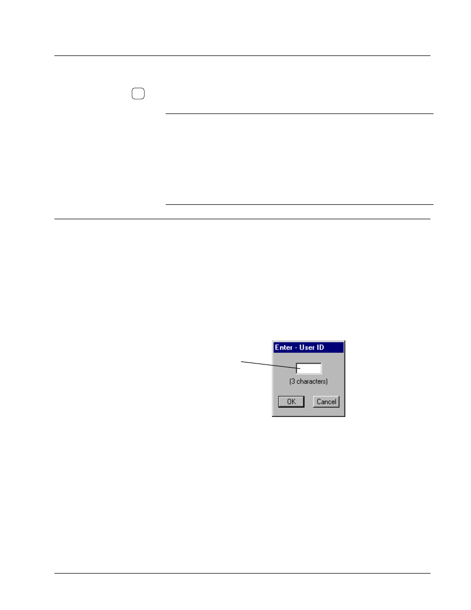
! To set a privilege level
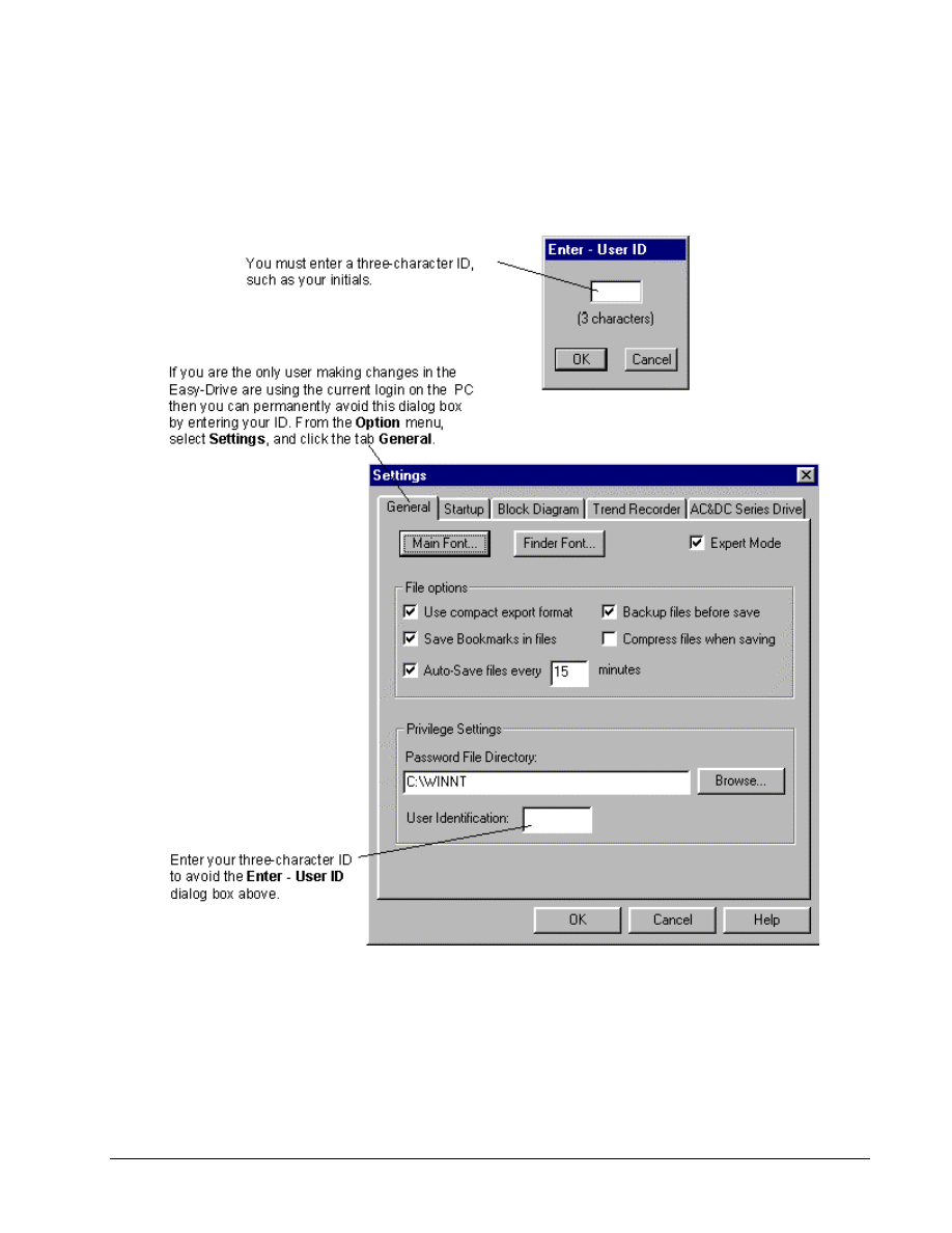
To avoid this dialog box, from
the Options menu, select
Settings, and then click the
tab General. At the bottom of
the dialog box in the text box
User Identification, enter
your user ID.
"
From the Options menu, select
Privilege.
Enter a three-character ID,
such as your initials.
Click OK.
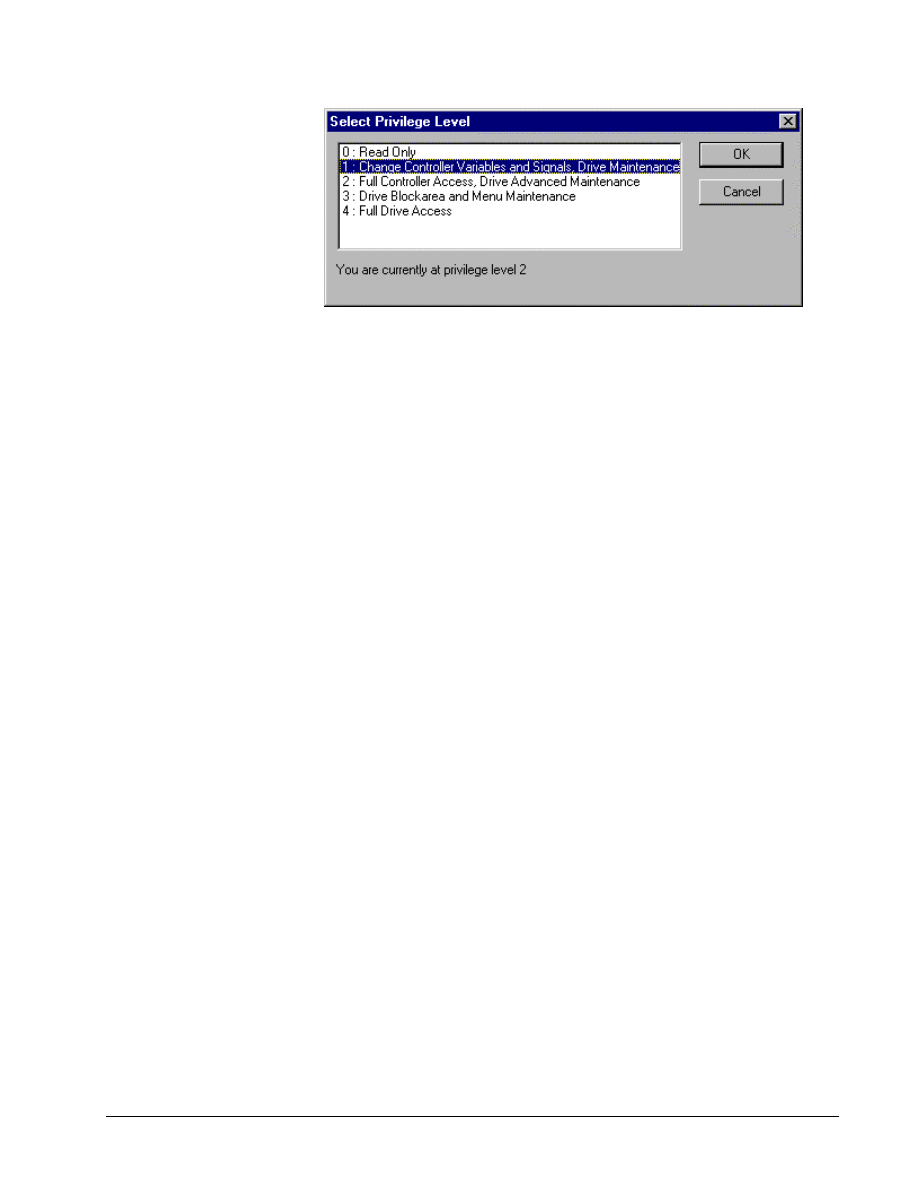
Privilege Level Functions
A password can be assigned to each of the Easy-Drive privilege levels defined in the
following table. (Each successive level allows all the functions of the previous level.)
GEH-6412A Easy-Drive for Ac & DC Version 2 Drive
Chapter 3 Using the Easy-Drive
••••
G-13

G-14
••••
Chapter 3 Using the Easy-Drive
Esay-Drive for AC & DC Version 2 Drive
Privilege Levels
Level
Functions
0: Read Only
View code
Use the Finder
Monitor live data
Trend (including saving trend definitions in .TRN
files and saving collected data)
Change View attributes under Option menu,
Settings
Print blockware code and reports
Change the password for level 0
1: Change drive Advanced
Maintenance
All functions allowed in Level 0, including change
password levels in Levels 0 and 1
Change the value of variables
2: Full drive Advanced
Maintenance
All functions allowed in Level 0 and Level 1
Make code changes
Download
Import/Export
Put in database and Get from database
Validate, build, save, backup, and pack signals
Change the password for Levels 0, 1, and 2
Change the location of the password file
3: Drive Block Area and
Menu Maintenance
Alter block area and change application menu
structure
4: Full Drive Access
Change parameters
View parameters that are not on a menu
Download firmware
GEH-6412A Easy-Drive for Ac & DC Version 2 Drive
Chapter 3 Using the Easy-Drive
••••
G-15
Change Password or Default Password Directory
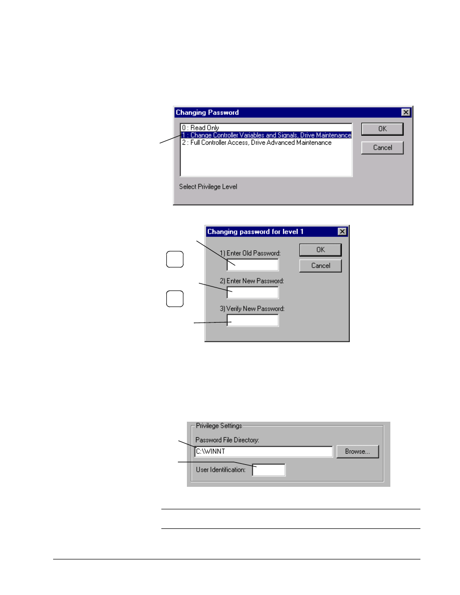
! To change the password
"
From the Options menu, select Password. The Changing
Password dialog box
displays
.
Select the privilege
level that you want
to change.
Click OK.
The Changing
password dialog
box displays for the
selected level.
Enter the old password
in text box 1) and press
the Tab key.
Enter the new password
in textbox 2) and press
the Tab key.
Enter the new password
again in text box 3) to
verify it is correct.
Tab
Tab
When a password is created, it is encoded in the file UCPASSWD.INI in the
Windows NT installation directory. This default directory can be changed by a user
at Privilege Level 2.
! To change the default password file directory
"
From the Options menu, select Settings, and then click the tab
General.
Enter a directory or click
Browse... to select a directory.
Enter three characters that
identifies the current user.
You will not be prompted for
initializations when values
change.
Note It is recommended that the password file be kept on the local PC to avoid loss
of access in the case of downtime on a remote node.
G-16
••••
Chapter 3 Using the Easy-Drive
Esay-Drive for AC & DC Version 2 Drive
Easy-Drive Options
Option settings are saved in
the your Windows registry
when the Easy-Drive is
closed.
The Easy-Drive’s working environment can be defined for each application. This
section describes each tab that can be set to customize the drive, such as general
settings, file loading at startup, block diagrams, Trend Recorder, and the AC&DC
Drive communication ports. These tabs are located in the Options menu, under
Settings.
! To customize the Easy-Drive settings
1.
From the Options menu, select Settings. The Settings dialog box
displays. Click on a tab to bring it to the front and select appropriate options.
2.
Click OK to apply the changes and close the dialog box. Click Cancel
to exit and not change any settings.
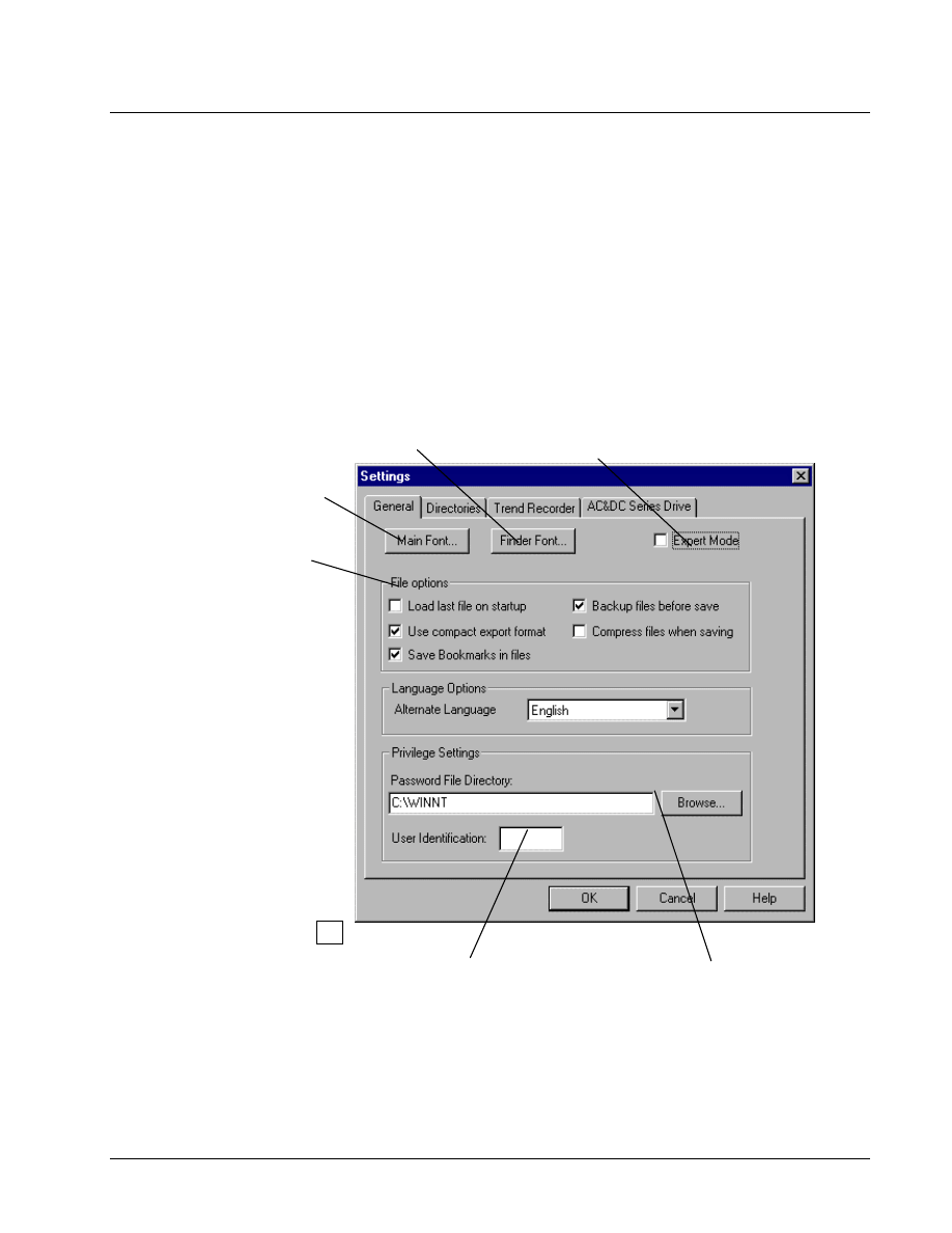
General
Select a font for the Outline
View. The default font is
System Bold.
Select a font for the
Finder.
Allows extra data to be seen, which is
useful to a Power User.
Select from the
following File options:
Use compact export format
compresses the .tre files
produced by exporting. Less
hard disk space is used and
is easier to read and edit.
This is recommended.
Save Bookmarks in files
saves bookmarks between
closing and reopening files.
Backup files before save
makes a backup copy of files
before saving new
information. This includes
.ucb, .dcb, .icb, and .ocb.
Compress files when
saving saves and stores files
in a compressed format,
which saves disk space.
Auto-Save files every
minutes automatically saves
the files at the set increment.
Enter the directory for the password
file. A local directory is recommended.
Click Browse… to search the directory
and choose a location.
Enter three character initials,
for use in the privilege/
password. You will not be
prompted for initializations
when values change.
GEH-6412A Easy-Drive for Ac & DC Version 2 Drive
Chapter 3 Using the Easy-Drive
••••
G-17
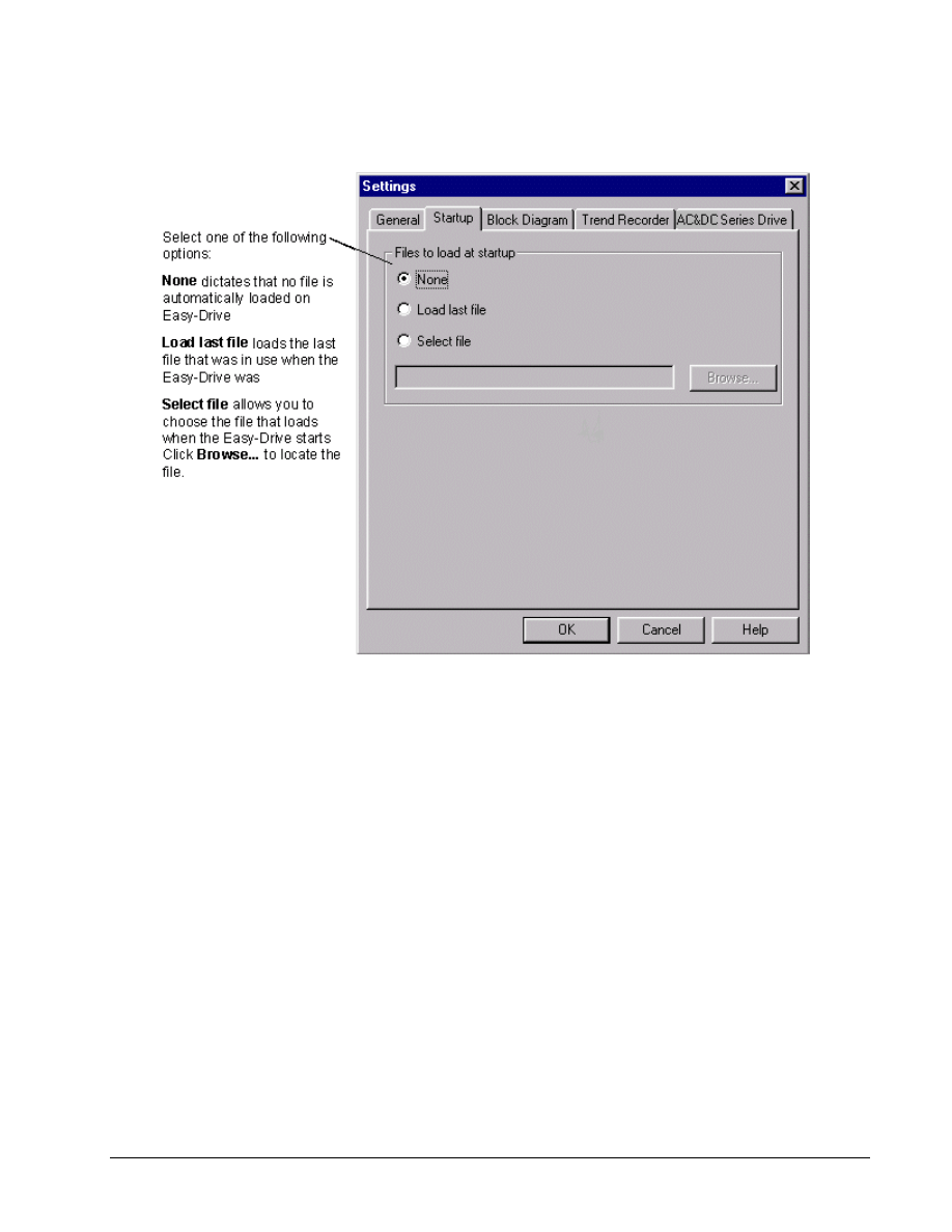
Startup
The Startup tab allows you to specify whether or not you want a file to automatically load at startup.
G-18
••••
Chapter 3 Using the Easy-Drive
Esay-Drive for AC & DC Version 2 Drive
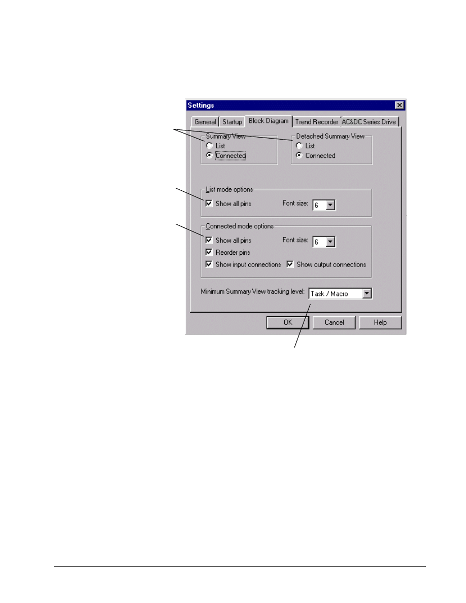
Block Diagram
The Block Diagram tab allows you to specify how the block diagram displays in the
Summary View and Detached Summary View.
Display the blocks in a list with
no connections or connected to
each other for the Summary View
and Detached Summary View.
Check to show all List block
diagram pins. This command
disregards the text box Visibility,
if it is checked in the Edit Macro
Pin Definition dialog box. Font
size changes the font size of all
text on the block diagram.
Check the following options for
interconnected block diagrams:
Show all pins displays all block
pins. This command disregards
the text box Visibility, if it is
checked in the Edit Macro Pin
Definition dialog box.
Reorder pins rearranges the
pins to minimize crossing the
connections on the diagram.
Show input or Show output
connections display the
connection names and values.
Font size changes the font size
of all text on the block diagram.
Change the Summary View tracking feature to display various levels
of the hierarchy, when they are chosen in the Outline View. Select
the item to display on the lowest level. The default Task/Macro.
GEH-6412A Easy-Drive for Ac & DC Version 2 Drive
Chapter 3 Using the Easy-Drive
••••
G-19
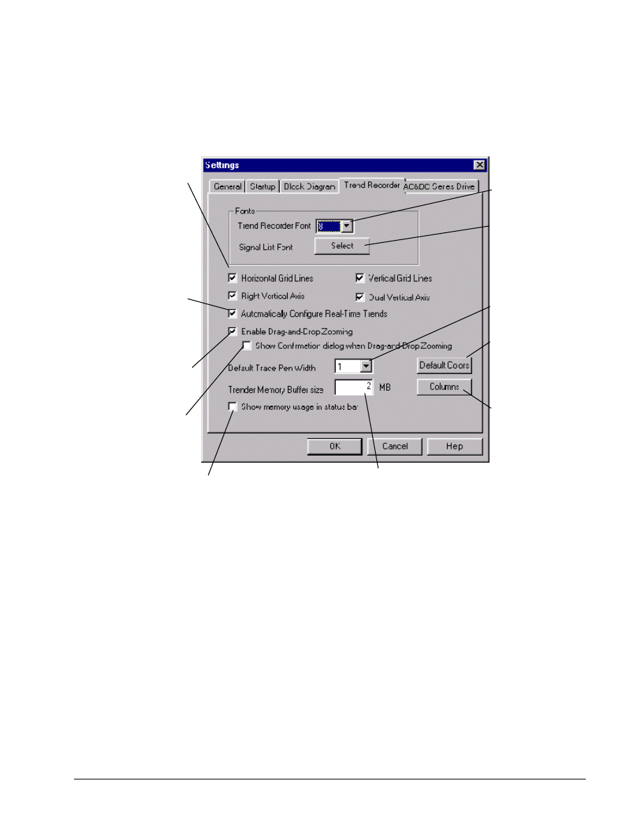
Trend Recorder
The Trend Recorder tab allows you to specify Trend Recorder options as follows:
Select any of the following
options:
Select the font
size used in the
Top Graph View
Enter the amount of memory the Easy-Drive
reserves for storing traces. The default value
of 2 MB allows 4 signals to be captured at 32
ms intervals for about 14 minutes before the
oldest data starts to be overwritten.
Click to display the
Font dialog and set
the font type and
size used in the
Lower Signal View.
Check to display the amount of
reserved memory that was used.
% Horizontal Grid Lines to
display horizontal grid
lines when in Replay
mode.
% Vertical Grid Lines to
display vertical grid lines
in Replay mode.
% Right Vertical Axis to
display vertical axis on the
right side.
% Dual Vertical Axis to
display the outer Y-Axis.
Check to zoom in the Trend
Recorder, using the mouse
to drag-and drop a rectangle
on the screen.
Check to automatically
configure the recorder with
predefined signals. ( This
option currently only works
with Innovation Series drives
and when performing Mark
VI I/O board calibrations. )
Check for a Yes/No
confirmation prompt
to display before the
zoom takes place.
Select the default pen
width (measured in
pixels) used to draw
the signal traces.
Click to display the
Trenders Default
Colors dialog from
where you can
change the pen
default colors for the
signal traces.
Click to display the
Trender Recorder
Signal View
Columns dialog
from where you can
select headings to
be displayed in the
Lower Signal View.
G-20
••••
Chapter 3 Using the Easy-Drive
Esay-Drive for AC & DC Version 2 Drive
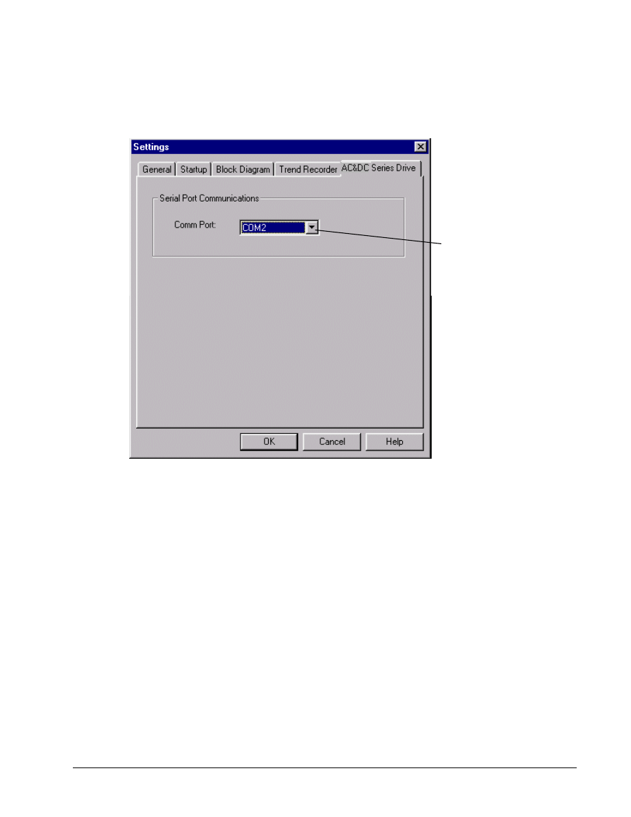
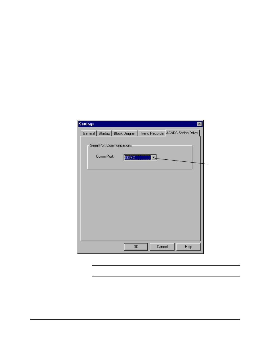
AC&DC Series Drive
The AC&DC Series Drive tab allows you to select the communication port specific
to the drive.
Click on the
drop-down list
and select the
communication
port.
GEH-6412A Easy-Drive for Ac & DC Version 2 Drive
Chapter 3 Using the Easy-Drive
••••
G-21
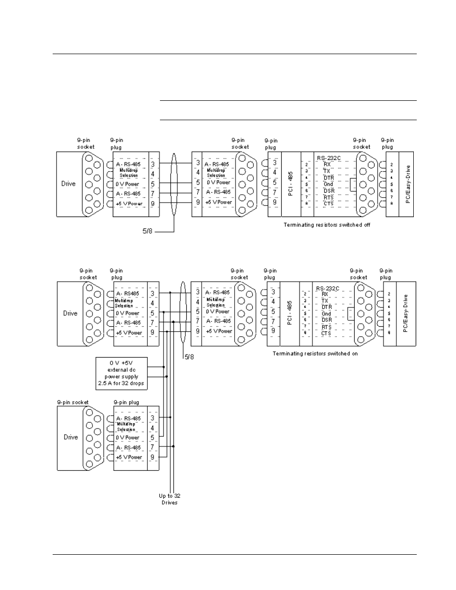
Connecting the Easy-Drive
The drive requires an
RS-232C to RS-485 converter.
The Easy-Drive can communicate with an AC & DC Version 2 drive through an
RS-232C/RS-485 serial port connection..
Note To connect to a drive, refer to Chapter 4, the section, Connecting to an AC &
DC Version 2 Drive. Only one drive at a time can go online (communicate).
Point to Point Communication
Multidrop Communication
G-22
••••
Chapter 4 Configuring an AC & DC Version 2 Drive
Esay-Drive for AC & DC Version 2 Drive
Chapter 4 Configuring an AC & DC
Version 2 Drive
Introduction
This chapter provides instructions for using the Easy-Drive to configure and monitor
an AC & DC Version 2 drive. In addition, information on using other features of the
Easy-Drive specific to the drive is also provided.
Creating an AC & DC Version 2 Drive
When the Easy-Drive starts, the Work Area is displayed (refer to the section,
Configuring the Drive). The Work Area is used to maintain the drive configuration
file in the Easy-Drive. You must create a new drive configuration file (.acb) or open
an existing one.
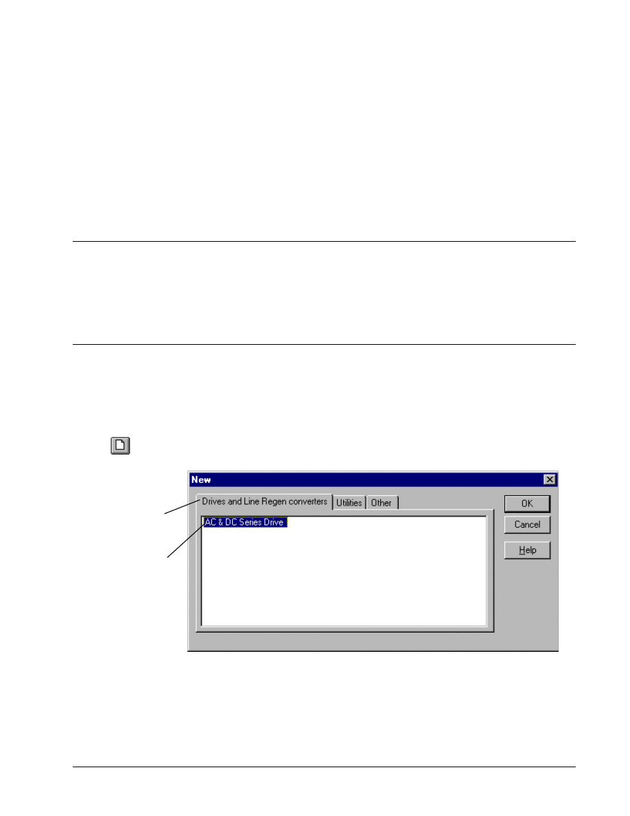
Or click
! To create an AC & DC Version 2 drive
"
From the File menu, select New. The New dialog box contains the installed
Easy-Drive products.
Click on the tab,
Drives and Line
Regen converters.
Click on AC & DC
Series Drive and
click OK.
A dialog box
displays to allow you
to choose the
Pattern and Version
for this drive.
GEH-6412A Easy-Drive for Ac & DC Version 2 Drive
Chapter 4 Configuring an AC & DC Version 2 Drive
••••
G-23
Pattern and Version
Drive Size
G-24
••••
Chapter 4 Configuring an AC & DC Version 2 Drive
Esay-Drive for AC & DC Version 2 Drive
Enter User Identification
To view these configuration
changes with User ID, from
the View menu, select
Reports.
If the Enter - User ID dialog box displays, you must enter an ID to identify the user
about to make changes to the configuration.
GEH-6412A Easy-Drive for Ac & DC Version 2 Drive
Chapter 4 Configuring an AC & DC Version 2 Drive
••••
G-25
Configuring the Drive
For details of the Easy-Drive
Work Area, see Chapter 3, the
section, Work Area.
The Easy-Drive Work Area is the main screen of an AC & DC Version 2 drive
configuration. This area is used to configure the drive.
If the Block Library and
Programmable Block Area
items are not listed, then your
version of drive firmware
does not support the
Programmable Block Area.
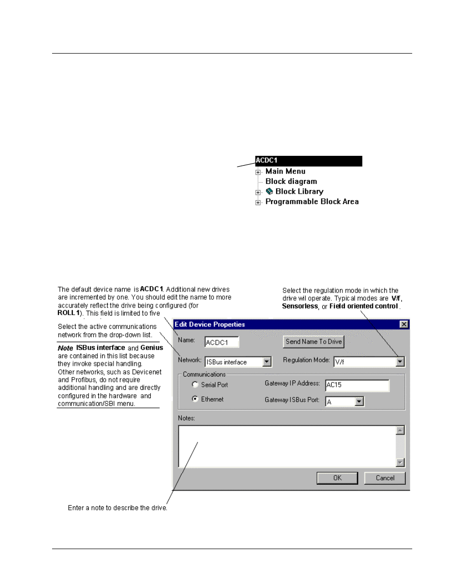
When a new drive is created or an existing file is opened, the Outline View displays
the drive name and the following items: Main Menu, Block diagram, Block
Library, and Programmable Block Area.
The default device name is ACDC1 (additional
new device names are incremented by one).
To modify the device name, see the next
section, Modifying Drive Properties.
Modifying Drive Properties
! To modify the drive
Or click the right mouse
button and select Modify.
1. From the Outline View, click on the drive name.
2. From the Edit menu, select Modify. The Edit Device Properties dialog box
displays.
G-26
••••
Chapter 4 Configuring an AC & DC Version 2 Drive
Esay-Drive for AC & DC Version 2 Drive
Validating the Drive
Also, items in the hierarchy
that had problems during
validation will display in red
after the validation.
Validation checks for errors that might prevent successful operation of the drive. If
the configuration needs to be validated, items in the Outline View display in red.
Note In most cases, the configuration is automatically validated.
Or click
! To validate the drive configuration
"
""
"
From the Drive menu, select Validate. The validation results display in the
Log View at the bottom of the Easy-Drive Work Area screen.
Entering Job-Specific Information
For more information, refer
to the section, Wizards.
Once a new drive has been created and the properties are modified, you must enter
job-specific data, such as motor hp, motor amps, and motor speed. This information
can be entered in a new configuration using the menus or the Offline commissioning
wizard.
Or click
! To configure the drive offline
1. From the Edit menu, select Wizards.
If more than one wizard is defined, the Choose Wizard dialog box displays.
Select Offline Basic Commissioning Wizard. However, if only one wizard
is defined, the Offline Wizard dialog box will display immediately.
Each configuration depends on application
requirements.
For more information, see the
section, Wizards.
2. Click Next to progress through the wizard. Enter the appropriate settings.
Note By entering the Offline Basic Commissioning Wizard information and
performing the applicable tune-ups, the drive should be sufficiently configured for
basic operation.
GEH-6412A Easy-Drive for Ac & DC Version 2 Drive
Chapter 4 Configuring an AC & DC Version 2 Drive
••••
G-27
Working with Files and Menus
An AC & DC Version 2 drive is configured using different types of files, as
described in the following sections. In addition, the menu commands are described in
this section.
File Types
The configuration files generate output files that can be downloaded to the drive.
Configuration files include:
Drive configuration file (.acb) is a binary working file that contains an exact copy
of the drive configuration used by the Easy-Drive. Users generally work from these
.acb files. When the file is saved, the prior .acb is renamed to Backup of File. For
example DeviceName.acb would have a backup file named Backup of
DeviceName.acb. To restore the backup copy, rename the file to an .acb file.
Setup files (.dat) consist of four binary files that exist in the drive and save motor
and drive data including measured values. These setup files, combined with the
configuration file (.acb) constitute a complete backup of a drive configuration.
Diagram files (.wmf) are drawing files that contain the Easy-Drive block diagrams.
Help files (.hlp) provide product-specific help from within the Easy-Drive
The .tre and .prj files are not
normally used by users.
Tree files (.tre) are text files that contain configuration information for the drive.
Some .tre files define the parameters, faults, menus, and other items that exist within
a particular drive, while others store configurations for transport between different
drives, and possibly different versions of the Easy-Drive.
Project files (.prj) are text files that hold some drive configuration information.
They are used in conjunction with other tree files, to transport configurations across
versions of drive products, and possibly different versions of the Easy-Drive.
Back up all files often to avoid losing data.
*.acb file
Save
Open
Export/Import
Windows NT or
Windows 95
running toolbox
hardware,
library, and
function .tre
files
Upload/
Download
parameters
Documentation
Programmer Workstation
Pattern configuration files,
such as .tre, .wmf, .hlp
Create/New
AC & DC Version 2
Drive
e
AC & DC
G-28
••••
Chapter 4 Configuring an AC & DC Version 2 Drive
Esay-Drive for AC & DC Version 2 Drive
Opening and Closing Files
Opening a drive configuration file (.acb) reads a previously saved drive
configuration into the Easy-Drive.
! To open a file
Or click
Check the Release Notes
located in the Easy-Drive
Help menu, under About
Easy-Drive.
1.
From the File menu, select Open. The Open dialog box displays.
2.
Select the file name and click OK.
Note If an older version Easy-Drive is used to open a drive configuration file (.acb)
that was saved with a newer version, a Warning message is displayed. Either install
the version of Easy-Drive the drive configuration file (.acb) was saved with (listed in
the Warning) or consult the Easy-Drive Release Notes to see if they are compatible.
! To close a file
" From the File menu, select Close.
Closing a file removes the configuration from the Easy-Drive. If the configuration
has not been saved, a dialog box displays and asks if the configuration should be
saved.
Saving Files
Or click
Saving a file writes the entire contents of the configuration to a drive configuration
file (.acb). The prior drive configuration file (.acb) is renamed to a Backup of
filename.icb file and used as a backup file.
! To save a file
1.
From the File menu, select Save. The Save As dialog box displays.
2.
Enter the file name and click OK. (Once a configuration has been saved, the
Save button saves the new file without asking for a file name.)
Tip
$
The Save button also indicates that a change was made to the configuration
by highlighting (red) and becoming enabled. If the computer or Easy-Drive fails
when the button is red, all changes since the last save is lost, so save files often (or
make sure that the Auto-save function is not disabled).
Upgrading a Configuration
Refer to Chapter 3, Using the
Easy-Drive.
The Upgrade command adds the required functions of a newer version of the product
to the current drive configuration file. For example, if the current drive configuration
file (.acb) is version V02.02.01B, and the application requires the functions of
version V02.03.00C, you would need to upgrade the .acb file.
GEH-6412A Easy-Drive for Ac & DC Version 2 Drive
Chapter 4 Configuring an AC & DC Version 2 Drive
••••
G-29
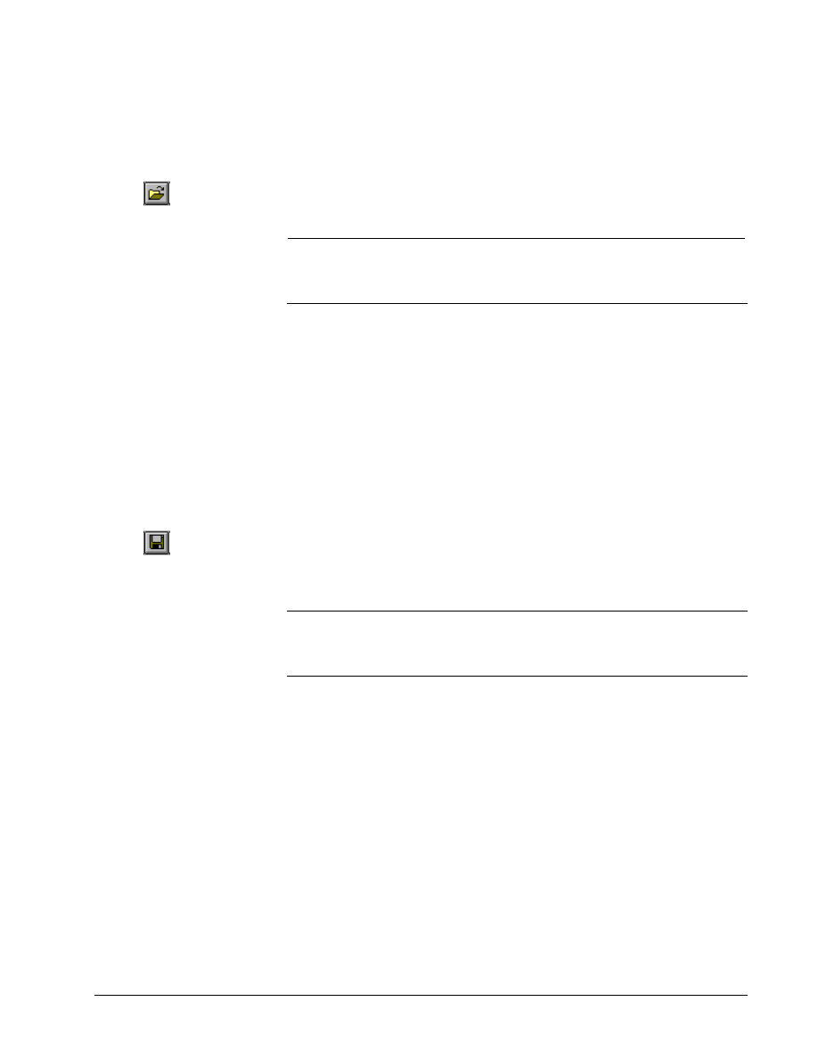
! To upgrade a configuration file
1. Make sure the new required version is installed (refer to Chapter 3).
2. From the current drive configuration file, such as version V02.02.01B described
above, from the File menu, select Upgrade…. The following message box
prompts to proceed you with the upgrade.
Click Yes
to upgrade the drive.
The Select Upgrade
Version dialog box
displays.
Selecting the Upgrade Version
When you select to upgrade the drive, the Select Upgrade Version dialog box
displays all of the newer installed versions.
Select the
updated version.
Click OK.
The following dialog box displays, showing that the version upgrade was successful.
G-30
••••
Chapter 4 Configuring an AC & DC Version 2 Drive
Esay-Drive for AC & DC Version 2 Drive
Exporting Configuration Files
The .tre files can be exported
selectively or for an entire
drive.
The parameter values contained in a drive configuration file (.acb) can be exported
in a .tre file format. Exporting drive parameters allows settings among drives to be
shared.
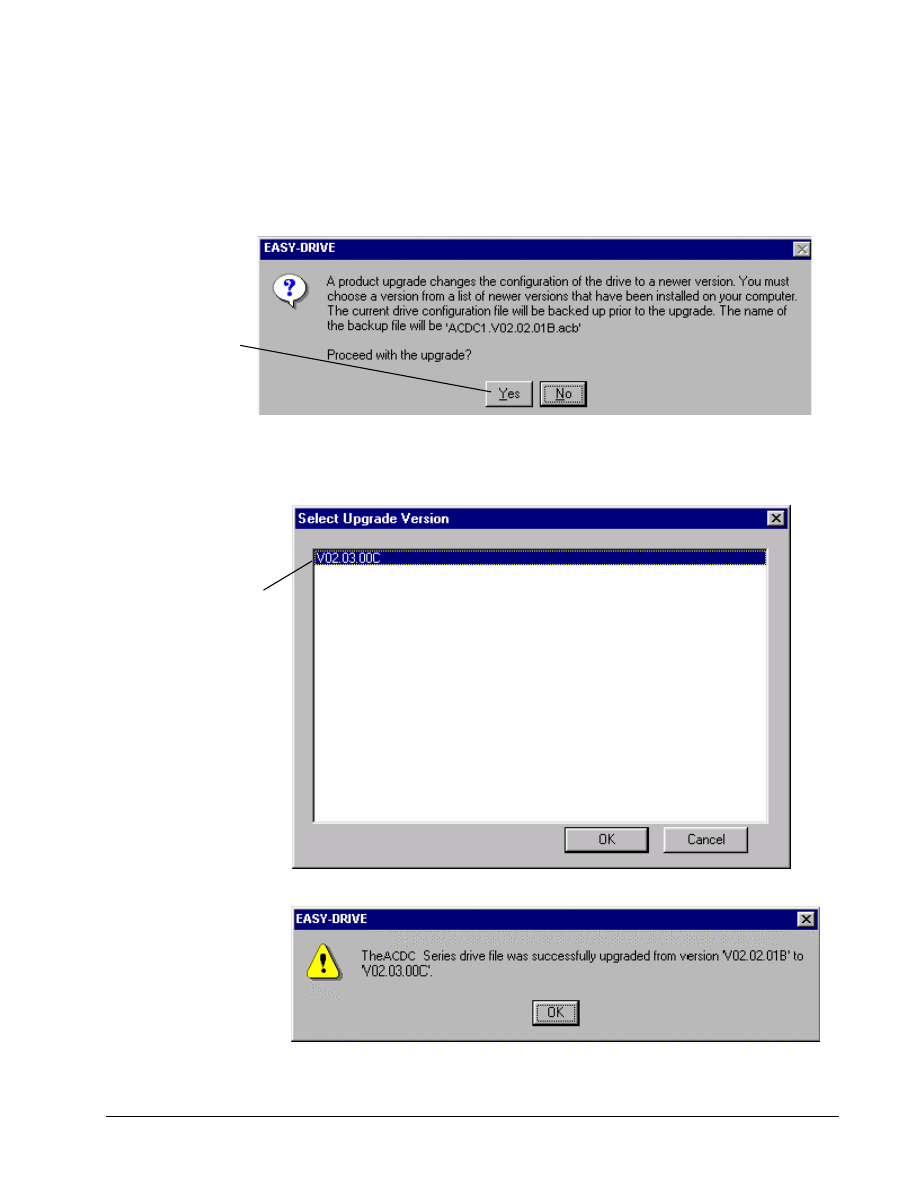
! To export parameter values
1. From the File menu, select Export, and then select Parameter Values. The
Parameter Values File Name dialog box displays.
2. Confirm the current project directory and file name or select a new directory.
Click Save. The file is saved as a .tre file.
Exporting and Opening Project Files
Generally this option is not required. It is provided if a
newer version of the Easy-Drive makes a change to the
format of the drive configuration file (.acb) that is not
backward compatible.
Project files allow you to
export and import a drive
configuration without having
to know about all the files it
contains.
Normally, newer versions of the Easy-Drive can load drive configuration files
created by older versions. However, if there is a major change of functionality in the
Easy-Drive, the Easy-Drive may not be able to load the drive configuration file. In
this case, it is necessary to first export the drive configuration file to a project (.prj)
file and then import it into the new version of the Easy-Drive. A project file is a text
file, which contains the names of all .tre files in a configuration. Project files save
the drive configuration in a form that can be loaded by all newer versions of the
Easy-Drive.
! To create a project file
1. From the Outline View, click on the drive name.
2. From the File menu, select Export and select All. All .tre files and the .prj file
are exported.
Once a project file exists, it can be used to create a drive configuration file (.acb).
Using the File \ Open command, choose a .prj file. This creates an AC & DC
Version 2 drive and starts a series of file imports. The Easy-Drive imports the files
listed in the .prj file, including the parameter values file.
GEH-6412A Easy-Drive for Ac & DC Version 2 Drive
Chapter 4 Configuring an AC & DC Version 2 Drive
••••
G-31
Menu Commands
The Easy-Drive work area contains the following Menu bar:
File Menu
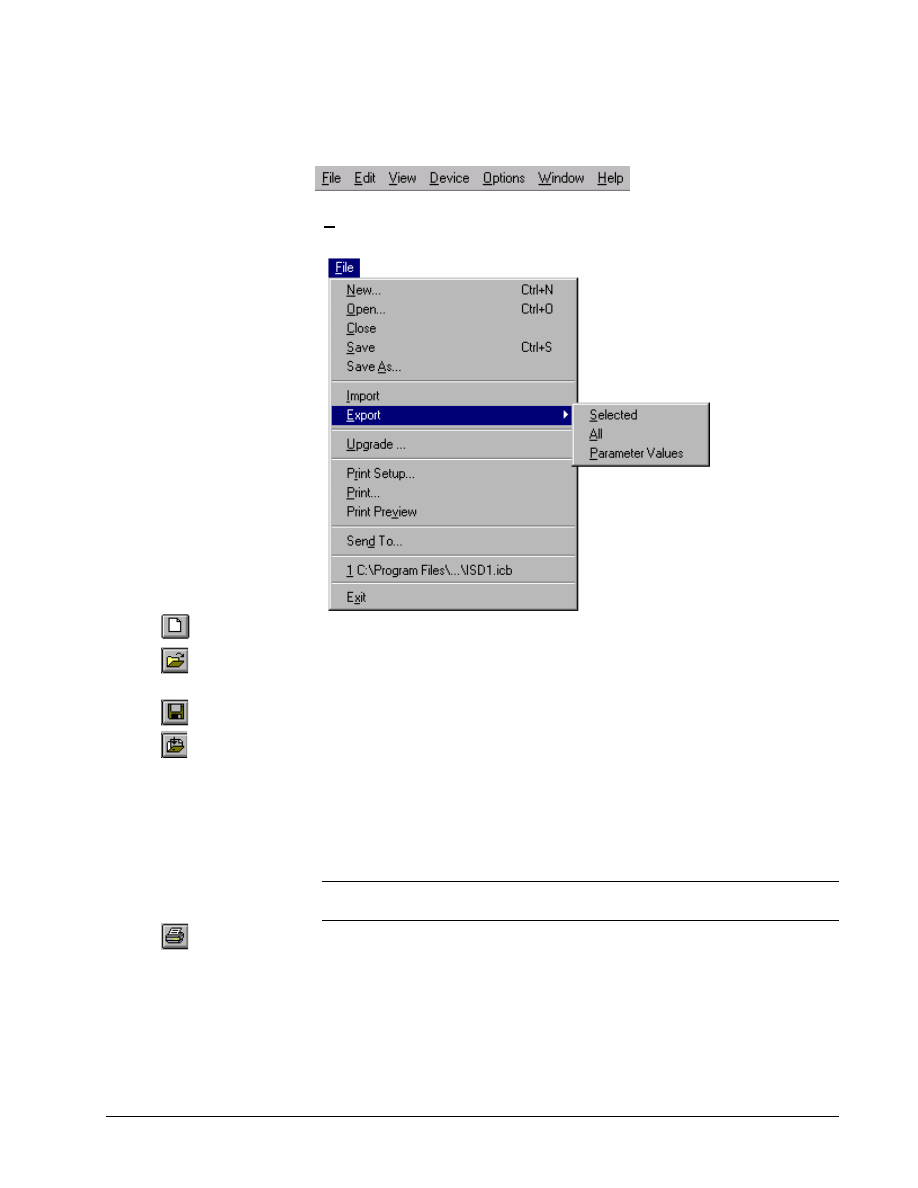
The File menu allows you to perform file operations with the following commands:
Or click
New creates a new drive configuration file.
Or click
Open loads an existing drive configuration file into the Easy-Drive.
Close exits an existing drive configuration.
Or click
Save/Save As saves an opened drive configuration file to a specified name.
Or click
Import retrieves values from the specified file. The values in the current
configuration are replaced with the imported values.
Export sends specified items (such as parameters and files) to a designated file.
Upgrade automatically makes the required changes to upgrade an older product
version to a newer version.
Print Setup allows you to choose a printer and printer connection.
Tip
$
The block diagram is designed to print best in Landscape Orientation. Refer
to the section, Block Diagrams/Printing Diagrams.
Or click
Print provides a paper (hard) copy of a specified file or page.
Print Preview displays the page as it would be printed.
Send To… opens email and provides a copy of the currently opened file to send
(you must have Window messaging, such as Exchange).
File 1, 2, 3... lists and opens the most recently used files.
Exit closes the Easy-Drive.
G-32
••••
Chapter 4 Configuring an AC & DC Version 2 Drive
Esay-Drive for AC & DC Version 2 Drive
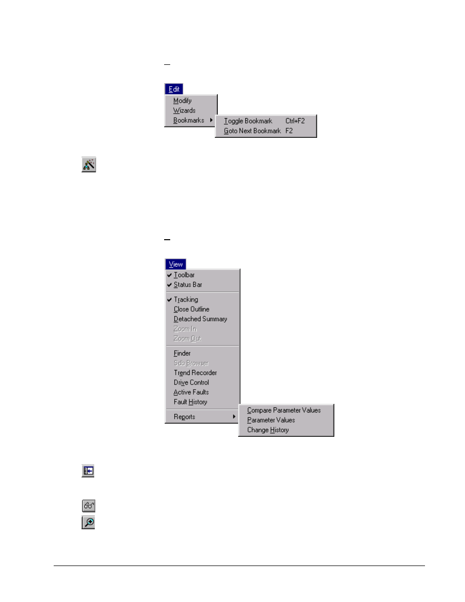
Edit Menu
The Edit menu allows you to edit items with the following commands:
Modify allows you to edit the highlighted item.
Or click
Wizards allows you to choose from a list of wizards used for drive configurations
commissioning, tests, and tune-ups.
Or press Ctrl+F2 to toggle
the mark and F2 to go to the
next bookmark
Bookmarks allows you to mark major items in the Outline View by using the
Toggle Bookmark option and then move between these items easily by using
Goto Next Bookmark.
View Menu
Some of these commands can
be toggled on and off. A check
mark (
#
) displays next to the
command name when the
feature is on and it will
display in the Easy-Drive.
The View menu allows you to manage the drive with the following commands:
Toolbar displays or hides the Toolbar.
Status Bar displays or hides the Status bar.
Or click
Tracking toggles the tracking feature of the Summary View on and off.
Close Outline reduces the hierarchy list of items displaying in the Outline View to
just the drive level.
Or click
Detached Summary creates a detached window of the diagram Summary View.
Or click
Zoom In enlarges the view of the block diagram area (Summary View).
GEH-6412A Easy-Drive for Ac & DC Version 2 Drive
Chapter 4 Configuring an AC & DC Version 2 Drive
••••
G-33
Or click
Zoom Out reduces the view of the block diagram area (Summary View).
Or click
Finder starts the Finder view to search for items, such as text and variables within a
configuration.
Sdb Browser starts the SDB Browser window to search the System Database
Or click
Trend Recorder is a separate window in the Easy-Drive
Or click
Or double-click on the status
bar (yellow indicates an
alarm or red indicates a
fault).
Drive Control starts the Drive Control view used to start and stop the drive. It also
provides specific information, such as motor speed, volts, amps and power.
Active Faults displays a list of all active faults and alarms. Each fault is time
stamped so that the order of events can be determined.
Fault History displays a list of faults that are saved in the drive.
Reports allows you to produce a Compare Parameters Values report that
shows all parameters whose values in the Easy-Drive are not the same as in the
drive, a Parameter Values report that displays all parameters and their values in a
menu hierarchical structure, and a Change History report listing changes made to
the drive configuration file.
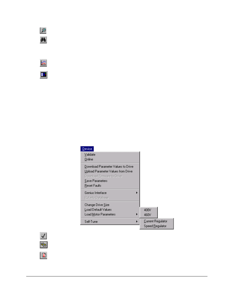
Device Menu
The Device menu allows you to manage the drive with the following commands:
Or click
Validate verifies that the drive configuration does not contain errors.
Or click
Online/offline toggles to start or end communications between the Easy-Drive and
the current drive.
Or click
Download Parameter Values to Drive sends the values of all the parameters
from the loaded drive configuration files to the current drive.
G-34
••••
Chapter 4 Configuring an AC & DC Version 2 Drive
Esay-Drive for AC & DC Version 2 Drive
Or click
Upload Parameter Values from Drive reads all the parameter values from the
current drive and replaces the values in the currently loaded drive configuration file
in the Easy-Drive.
This option enabled only if
you are at Privilege Level 4
and in Expert Mode.
Download Firmware to Drive sends the drive firmware configuration to the
selected version number.
Save Parameters saves the current active set of parameter values in the drive to
permanent storage
Reset Faults resets all faults that are currently active in the drive.
Genius Interface Not enabled for Easy-Drive.
This option enabled only if a
network is enabled.
Put into Database puts information into the Innovation Series Controller SDB to
allow drives to share signals with other drives and controllers on the network.
Change Drive Size allows you to change the drive size information in the file,
drive, or both.
This option requires the drive
to be online and not enabled.
This option requires the drive
to be online and not enabled.
Load Default Values loads the factory defaults in the drive and the currently
loaded drive configuration file in the Easy-Drive.
Load Motor Parameters loads the motor defaults for the 400 V or 460 V motor
parameters in the drive and the currently loaded drive configuration file in the Easy-
Drive.
Self-tune allows you to activate the self-tune process where the drive and the motor
perform predefined tests on either the Current Regulator or the Speed
Regulator to determine the best running conditions for the system.
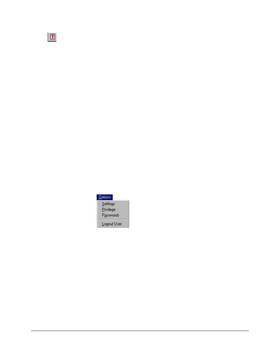
Options Menu
The Options menu allows you to manage general options for Easy-Drive operation.
Settings allows you to set general Easy-Drive options.
Privilege sets the privilege level for a session.
Passwords sets the password for a privilege level.
Logout User closes the current user from the current session and sets the privilege
level back to 0.
GEH-6412A Easy-Drive for Ac & DC Version 2 Drive
Chapter 4 Configuring an AC & DC Version 2 Drive
••••
G-35
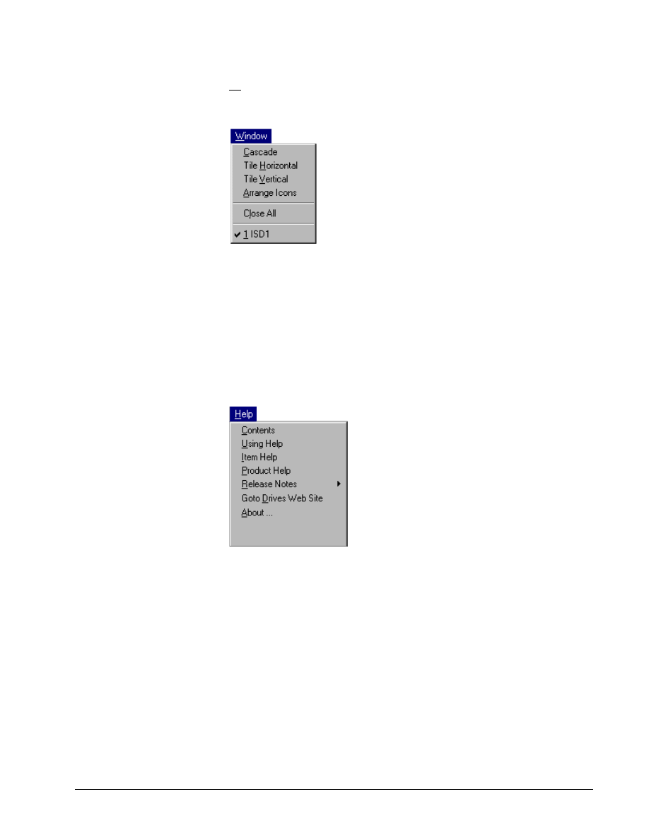
Window Menu
The Window menu arranges multiple views of open documents in the drive window
with the following commands:
Cascade arranges the windows in an overlapped style.
Tile Horizontal arranges the windows horizontally in non-overlapped tiles.
Tile Vertical arranges the windows vertically in non-overlapped tiles.
Arrange Icons arranges the icons of closed windows.
Close All closes all open windows.
Help Menu
The Help menu has the following commands:
Contents displays Help files for the Easy-Drive. It also contains the Find tab with a
work list to search for specific topics.
Using Help displays general instructions on how to use Help.
Item Help displays help for the item selected in the Outline View.
Product Help displays the Help file for the currently loaded pattern. The file
contains help on parameters, faults, diagrams, and wizards.
Release Notes provides product changes in the Easy-Drive.
Goto Drives Web Site takes you to the Low Voltage AC Drives page.
About … displays the version number and platform for this Easy-Drive.
G-36
••••
Chapter 4 Configuring an AC & DC Version 2 Drive
Esay-Drive for AC & DC Version 2 Drive
Concepts
The following section defines items and features used when configuring an AC&DC
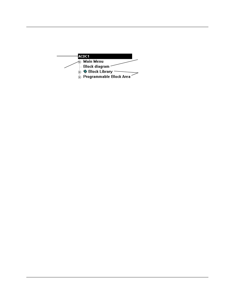
Version 2 drive. When a drive is created, the Work Area displays as follows:
The drive name
can be modified.
Main Menu contains
the configurable items.
Click to display a drawing of the
block diagram and signal flow.
Creating a new drive configuration file
automatically imports the Block Library
and Programmable Block Area
Parameters, located with the Main Menu, allow you to configure the drive behavior.
Each parameter has a name with up to 20 characters, which identifies it and helps to
convey its use. A parameter also can have units, such as RPM, displayed with the
Easy-Drive and keypad. The unit field is limited to five characters. Each parameter
contains a value, which can be a number or a setting. The value is adjusted to modify
the drive behavior. Examples of basic parameters and their associated units are
Motor rated current (Amps), Motor rated freq (Hz), Motor rated voltage (Volts), and
Regulator type. Parameters can be set and modified from the Outline View under the
items Main Menu or Block diagram, or from a Wizard or the keypad.
Variables, similar to parameters, have a name up to 20 characters and a 5-character
unit field. However, unlike parameters, you cannot change variables. They are
changed by the drive as a result of the execution of the pattern within it. For
example, the variable Speed feedback (RPM ) gets updated on a continuous basis and
represents the drives actual speed.
Block diagrams provide an overall picture of signal flow, sequencing and regulator
control in the drive. While communicating with the drive, the diagrams display drive
variables and their real time values. Contact and coil states are also indicated. Certain
drive parameters can be modified from this view (refer to the section, Block
Diagrams).
GEH-6412A Easy-Drive for Ac & DC Version 2 Drive
Chapter 4 Configuring an AC & DC Version 2 Drive
••••
G-37
Configuration
Parameters
For detailed information
about a parameter, click on
the parameter and press F1.
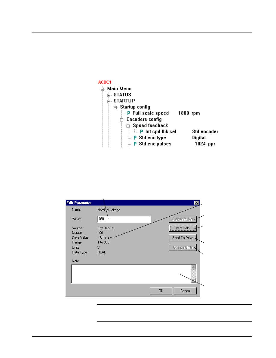
The drive contains a set of parameters with values, together with the pattern and
version, that define the drive behavior. In the Outline View of the Easy-Drive,
parameters display as follows:
Editing Parameters
Use the Finder to easily
locate a specific parameter.
Or click the right mouse
button and select Modify.
! To modify a parameter
1. From the Outline View, click on the parameter to modify.
2. From the Edit menu, select Modify. The Edit Parameter dialog box displays.
This function is currently
not available.
Click to display the
detailed Help for this
parameter.
Click to send the new
value to the drive.
This button may not be
enabled for all parameters.
It allows you to change the
display units (only effects
the displayed values and
not the drive control.)
The new value displays
under Drive Value.
Enter a new value (within the range) or, depending on the item, select a value
from the drop-down menu. Then, click Send To Drive for the value to take effect.
Enter a note for this
parameter, if desired.
Note When a parameter value is edited, you must click Send To Drive for the value
to take effect. Also, if you want to permanently save the parameter, select the Device
menu and then select Save Parameters.
G-38
••••
Chapter 4 Configuring an AC & DC Version 2 Drive
Esay-Drive for AC & DC Version 2 Drive
Easy-Drive / Drive Communications
For more information, refer
to the section, Connecting to
an AC & DC Version 2 Series
Drive.
The Easy-Drive can communicate with the drive through an RS-232C to RS-485
serial port connection. However, only one drive at a time can be selected to go
online (communicate), even if wired into a multi-drop configuration.
The serial port connection settings used by the Easy-Drive can be defined and
modified. These settings are saved and used by the Easy-Drive for every connection
to a drive whose drive configuration file is set to communicate serially.
Modifying Settings
! To modify the communications setting
1. From the Options menu, select Settings.
2. Click the tab, AC & DC Series Drive.
3. Modify the Serial Port Communications - Comm Port settings as desired
and click OK.
Click on the
drop-down list
and select the
communication
port.
Note Depending on the products installed, the number of tabs displayed in the
Settings dialog box may vary.
GEH-6412A Easy-Drive for Ac & DC Version 2 Drive
Chapter 4 Configuring an AC & DC Version 2 Drive
••••
G-39
Connecting to an AC & DC Version 2 Drive
Use the Window menu to view
multiple drive windows, when
drives are offline.
Multiple drives can be connected on the same network through an RS-485 link. Each
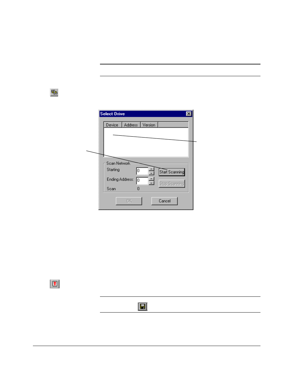
drive on the network has a unique name and address, and displays in the Select Drive
dialog box when you try to go online.
Note Only one drive at a time can be selected to go online. To select a different
drive, you must choose to go offline.
Or click
! To connect to an AC & DC Version 2 drive
"
From the Device menu, select
Online. The Select Drive dialog box displays.
When the drive first goes
online or requires
updating, adjust the range
of addresses to be
scanned on the RS-485
link.
Click the Start Scanning
button. A list of drives
displays in the list box.
Select the drive to connect
to. Click OK.
Or, double-click on the
drive name.
Drive
0
V2.000
Uploading Parameter Values
Parameter values can be uploaded from the drive to the Easy-Drive to save the drive
settings in a Easy-Drive configuration file. An upload is necessary after a self-tune or
when values are modified using the keypad. The Easy-Drive reads all the values
from the drive and saves them in the Easy-Drive configuration file. In addition to the
parameter values, four binary setup files are also uploaded. The four setup files are
prefaced with the drive name (for example, AC&DC1setup0.dat). The .acb file and
the four setup files constitute a complete backup for the drive.
! To upload parameters
Or click
"
From the Device menu, select
Upload Parameter Values from the Drive.
Tip
$
Remember to save the Easy-Drive configuration file. From the File menu,
select Save or click
.
G-40
••••
Chapter 4 Configuring an AC & DC Version 2 Drive
Esay-Drive for AC & DC Version 2 Drive
Downloading Parameter Values
Parameter values can be downloaded from the drive to the Easy-Drive to restore the
drive settings to the drive from a Easy-Drive configuration file. A download is
necessary when a wizard is executed or when drive parameters are modified in the
Offline mode. Downloading parameters sends the values to the drive. There are two
types of downloads:
•
If the four setup files have been uploaded from the drive and are not out
of date, they are downloaded to the drive.
•
If no setup files exist or they are out of date due to changes made to the
configuration file, the drive is restarted in the Setup mode and new
setup files are created in the drive.
! To download parameters
Or click
"
From the Device menu, select
Download Parameter Values to Drive.
Downloading Firmware
For this function to be enabled, you must be at
Privilege Level 4 and operating in Expert Mode
(see Chapter 3).
Before downloading new firmware, ensure there is a
copy of the latest drive configuration file. All settings
are erased when new firmware is downloaded to the
drive.
Generally, this feature is not
necessary since the drive is
shipped with the correct
firmware already installed.
The Easy-Drive allows you to update the drive's firmware. Although seldom used,
this function may be necessary when new features are added to the drive.
! To upgrade drive firmware
1. Install the new product files containing the new .tre files, drawings, and
firmware.
2. Upgrade your configuration to the new version of product files (see the section,
Upgrading a Configuration).
3. From the Device menu, select Download Firmware to Drive.
GEH-6412A Easy-Drive for Ac & DC Version 2 Drive
Chapter 4 Configuring an AC & DC Version 2 Drive
••••
G-41
Block Diagram
The diagrams display in
landscape mode, the long
edge of the paper is
horizontal.
Diagrams provide an overall picture of signal flow, sequencing and regulator
control in the drive. While communicating with the drive, the diagrams display drive
variables and their real time values. Contact and coil states are also indicated.
Certain drive parameters can be modified from this view
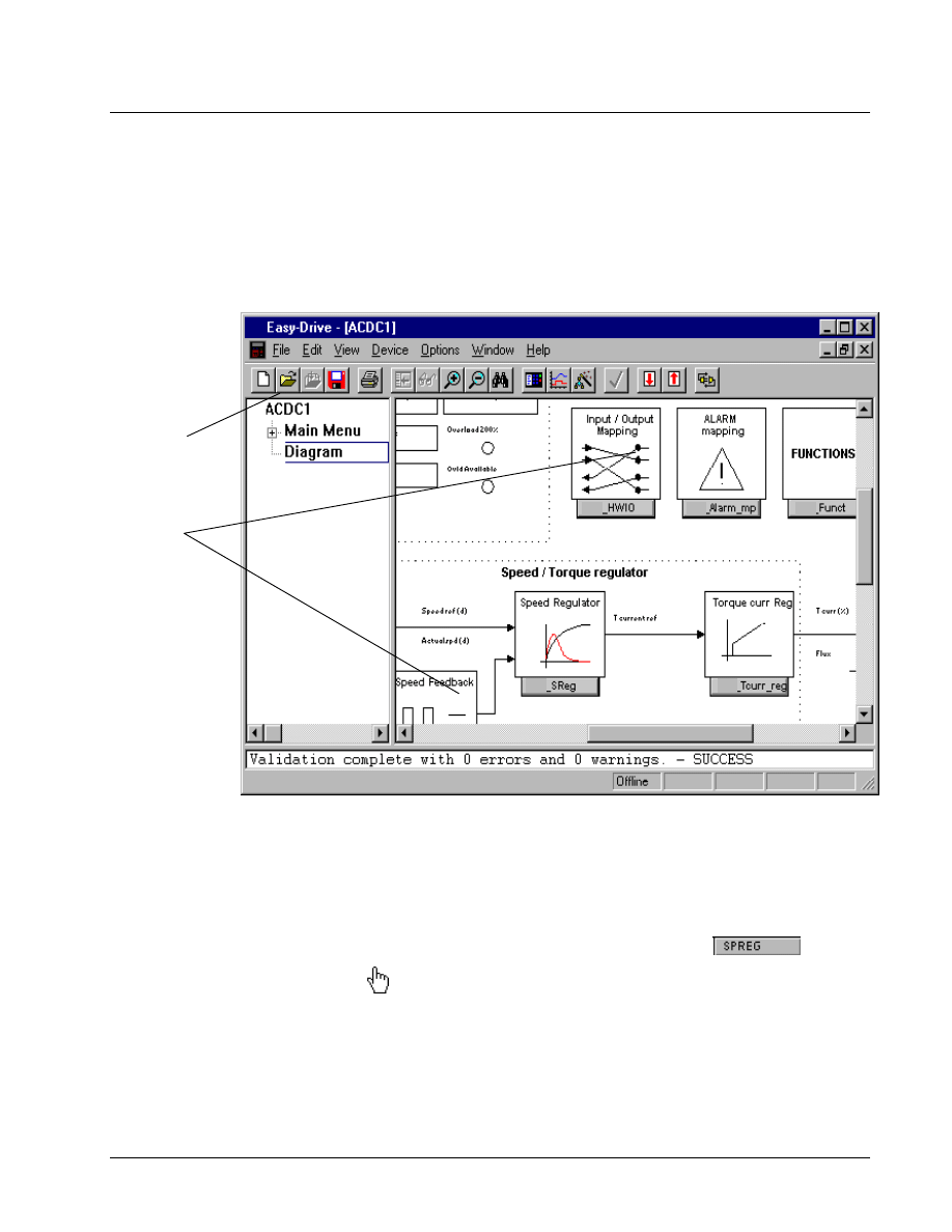
! To access diagrams
"
From the Outline View, click on the item Block diagram. The
Overview diagram displays in the Summary View.
Click Diagram to
view drive block
diagrams.
Click the various
link buttons in the
Overview diagram
to view details of
the block.
Use the scroll bars
to view the entire
Overview diagram.
Use the Print
command to print
the diagram.
Links to Other Pages
Diagram provides links to other pages, which contain information on drive functions.
! To access diagram links
1. From the Summary View, place the mouse pointer on a link button in the diagram, such as
.
2. When the pointer changes to a hand
, click on the link button. Another diagram displays with additional details
and links.
G-42
••••
Chapter 4 Configuring an AC & DC Version 2 Drive
Esay-Drive for AC & DC Version 2 Drive
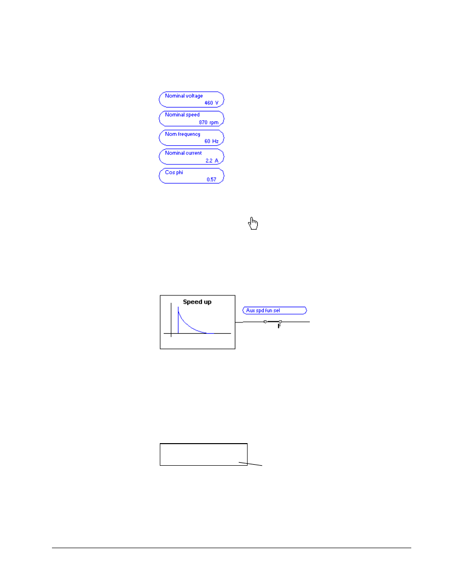
Modify Parameters from Diagram
Parameters can be modified from the diagram. In the diagram, the Easy-Drive
displays parameter names are displayed in blue as follows:
! To modify a parameter
"
From the block diagram, move the mouse pointer over the parameter
until it changes to a hand
. Click on the parameter. The Edit Parameter
dialog box displays (refer to the section, Edit Parameters).
Parameter Jumpers
In the Overview diagrams, parameter jumpers show how different paths of the block
diagram are connected together.
Live Data Display
If the Easy-Drive is connected to the drive, all variables on the diagram display live
values. On the Status bar, the scan rate shows the time it takes to update all the
variables on the currently selected page.
Variables
Green values are valid
numbers received from the
drive.
Variables can be monitored by the Easy-Drive. Live values display in green.
Actual spd (rpm)
422 rpm
Live value
GEH-6412A Easy-Drive for Ac & DC Version 2 Drive
Chapter 4 Configuring an AC & DC Version 2 Drive
••••
G-43
Drag-and-Drop Variables
Variables in the block diagram can be copied to the Trend Recorder using the
drag-and-drop feature.
Or click
! To drag-and-drop a variable in the
Trend Recorder
1. Within the block diagram, locate the desired variable(s) by clicking the
appropriate link buttons. The diagram (Summary View) displays full screen.
2. From the View menu, select Trend Recorder. The Trend Recorder window
displays on top of the Easy-Drive Work Area.
3. Resize and reposition the Trend Recorder window so that it and the block
diagram can be viewed (using regular Windows features).
Tip
$
To view both the Easy-Drive and the Trend Recorder, from the Window
menu, select Tile Horizontal or Tile Vertical and adjust the size of the windows.
4. From the diagram, place the mouse pointer over the desired variable. When the
pointer changes to a hand, press and hold the left mouse button. The pointer
changes to the drag-and-drop pointer
.
5. Continue to hold the left mouse button down and drag to the Trend Recorder
window. At the Trend Recorder, the pointer changes to the drop pointer.
6. Release the mouse button and the variable will drop in the Trend Recorder.
Printing Diagrams
Tip
$
The block diagram(s) is designed to print in Landscape Orientation. From
the File menu, select Print Setup and then click Landscape.
! To print block diagrams
Or click
1.
From the Outline View, click the item Block diagram.
2.
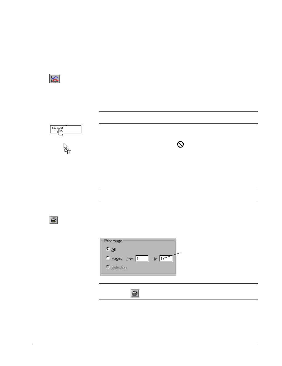
From the File menu, select Print. The Print dialog box displays.
3.
Enter the number of copies to print and the page(s).
This field shows that there are 17
diagrams in this device.
Click OK to print all the diagrams
or enter the page number(s) to
print.
Tip
$
To print a single block diagram, link to that page, so that it displays on the
screen and click
. Click OK. Live data can be printed, if the drive is online.
G-44
••••
Chapter 4 Configuring an AC & DC Version 2 Drive
Esay-Drive for AC & DC Version 2 Drive
Programmable Block Area
If the Block Library and
Programmable Block Area
items are not displayed in
your Outline View, then your
version of drive firmware
does not support the
Programmable Block Area.
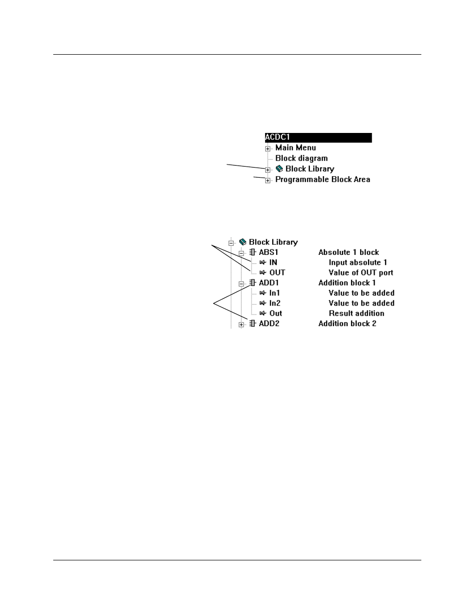
In addition to the Main Menu and Block diagram items, there are two other
top-level items that are listed in the Outline View: Programmable Block Area and
Block Library.
The Programmable Block Area provides a location to modify and extend the drive's
standard control logic. Additional calculations can be added to the drive without the
need for additional hardware.
Creating a new drive
configuration file
automatically imports the
Block Library and
Programmable Block Area
Block Library
The Block Library item can be expanded to display a list of available blocks. A
block represents a logical or arithmetic calculation, such as addition or integration.
Blocks pins can be connected to form custom
functions (for example, the output pin of an
Absolute Value block can be connected to one
input pin of an Addition block). Or pins can be
attached to constant values, drive variables,
and parameters.
Each block can only be used once. However,
there can be more than one of a particular type
of block.
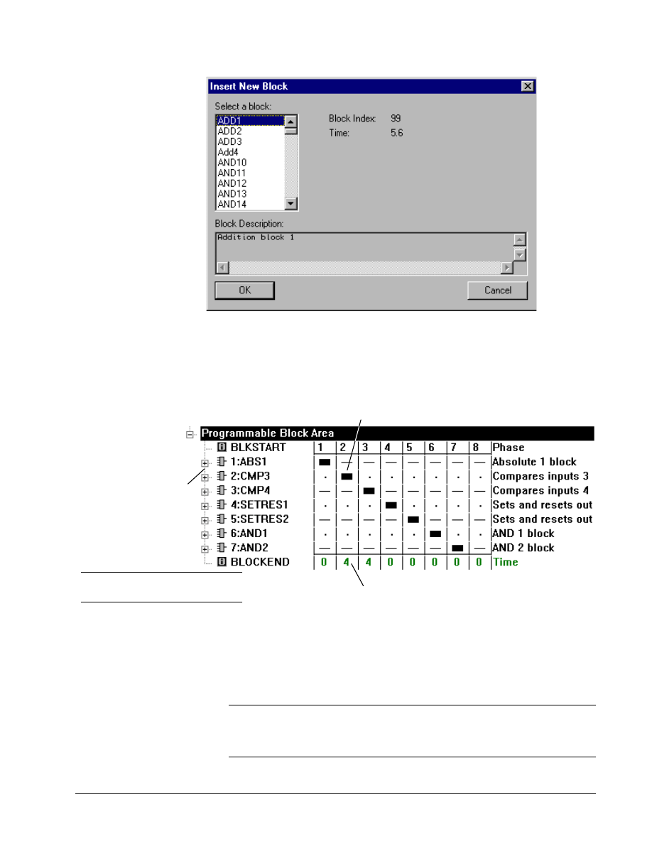
Inserting Blocks
Before blocks can be used, they must be inserted into the Programmable Block Area.
! To insert a block into the block area
" From the Outline View, right-click on Programmable Block Area and select Insert First from the pop-up
menu. The Insert New Block dialog box displays.
GEH-6412A Easy-Drive for Ac & DC Version 2 Drive
Chapter 4 Configuring an AC & DC Version 2 Drive
••••
G-45
Select the
block and
click OK
! To insert additional blocks
1. From the Outline View, right-click on the block that you want the new block(s)
to follow and click Insert Next. The Insert New Block dialog box displays.
2. Select the block and click OK. The newly inserted block displays in the Outline
View. Also, after selecting the block for use, it is removed from the list.
To distribute the load on the Drive's CPU, blocks can be
executed in any of eight phases as shown in the timing diagram.
Each phase's predicted CPU usage, in percent.
Note A maximum of eight blocks can
be executed in a particular phase
Blocks are inserted in this
area. The number shows
the order in which they are
executed.
Blocks can be executed at three rates: 1 ms, 2 ms, and 8 ms. Blocks running at rates
slower than 1 ms can be scheduled to run in one of eight phases, allowing the load to
be distributed. Each phase represents 1 ms. Since no more than eight blocks can be
executed in one phase, the Block Area is limited to a maximum of 64 blocks (eight
blocks in each of eight phases, all executing at the 8 ms rate). If this limitation is
exceeded, the block area cannot be downloaded to the drive. For more information,
refer to the section, Execution Order.
Note The 1 ms and 2 ms execution rates can consume excessive amounts of the
Drive's CPU time if not used carefully. For most applications, the 8 ms rate is
recommended. There are regulation modes that cannot use 1 ms rates at all due to
zero time available in one or more phases.
G-46
••••
Chapter 4 Configuring an AC & DC Version 2 Drive
Esay-Drive for AC & DC Version 2 Drive
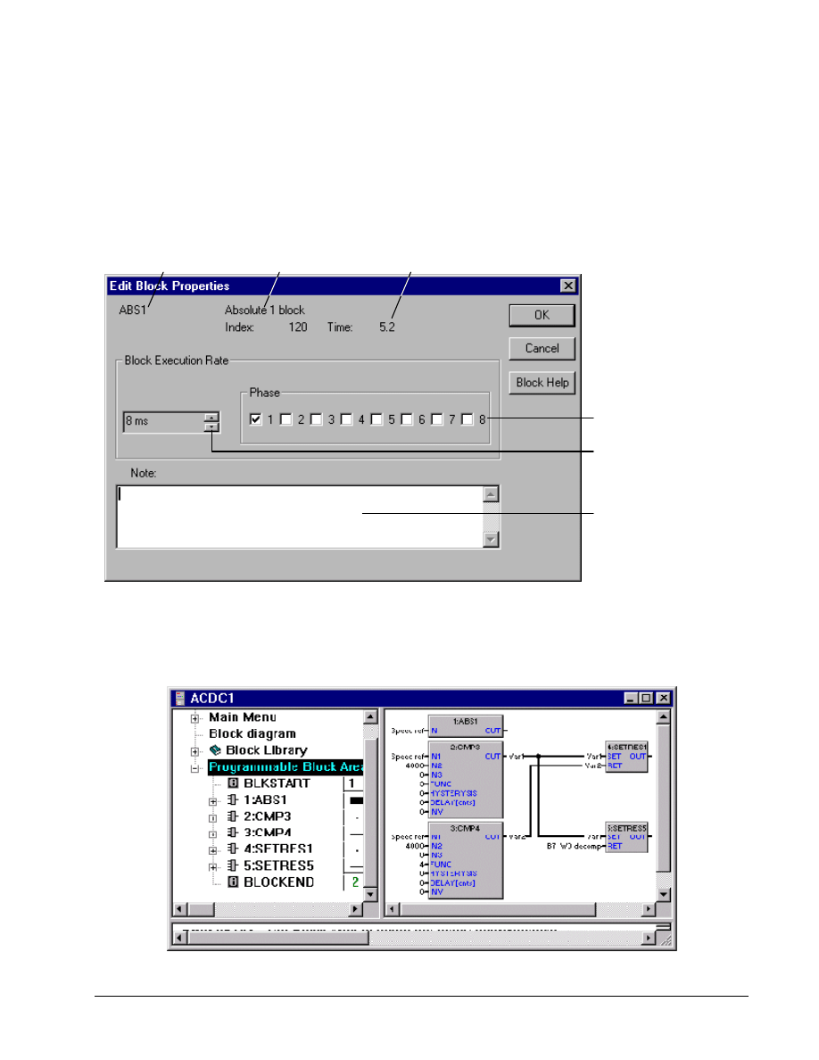
Modifying Block Properties
Once the blocks are inserted, you can change block properties, such as the execution
rate or phase.
! To change the execution rate or phase
Or click the right mouse
button and select Modify.
1. From the Outline View, click on the desired block.
2. From the Edit menu, select Modify. The Edit Block Properties
dialog box displays.
Block name
Description
Select the execution rate.
Select the Phase.
Enter notes.
Execution time in microseconds
Connecting Pins from Block Flow View
Once the desired blocks have been inserted into the Programmable Block Area, you
can connect block pins. Each block, with its associated pins, is shown in the Block
Flow View (right pane of the work area, or Summary View).
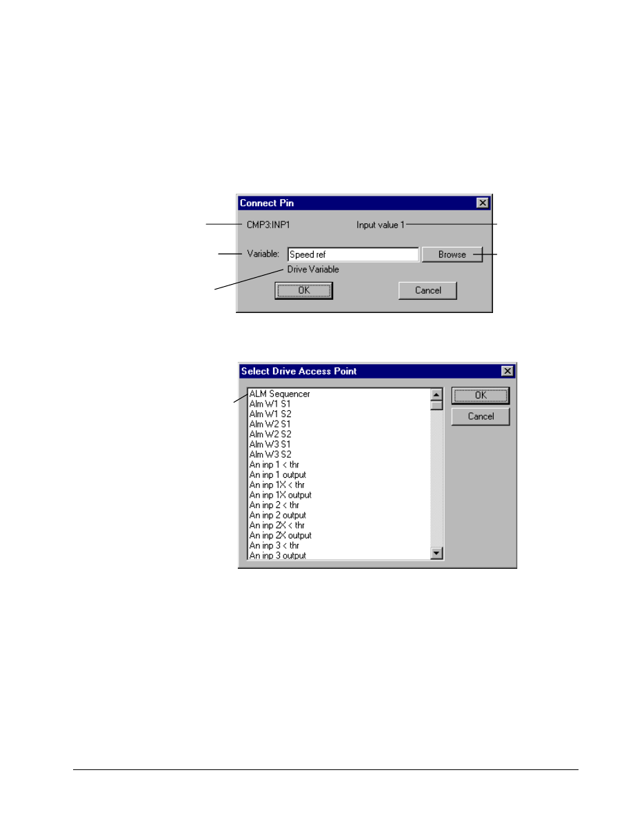
GEH-6412A Easy-Drive for Ac & DC Version 2 Drive
Chapter 4 Configuring an AC & DC Version 2 Drive
••••
G-47
! To connect block pins to block pins
"
From the Block Flow View, drag an output pin from one block to an
input pin of another block. Output pins cannot be connected together. Input pins
can be connected only if one of the input pins within its block is already
connected to an output pin.
! To connect block pins to drive variables, parameters, and constants
"
From either the Block Flow View or the Outline View, double-click on
a pin. The Connect Pin dialog box displays.
Pin Name
Enter either a constant value, the
full name of a drive variable, or
parameter. Then click OK.
Click to display
a list of drive
variables and
parameters.
Pin Description
Description of the selected
variable or parameter.
From this dialog, you can connect a subset of drive variables and parameters to Input
pins, connect a subset of drive parameters to Output pins, or connect a constant value
to a pin.
Select a drive variable
or parameter.
Click OK.
Execution Order
Order is important when the output of one block feeds the input of another. If the
output's block is executed after the input's block, the value actually read by the input
will be delayed by the period of the block's execution rate. You are responsible for
inserting blocks in the proper order.
Within a phase, the block that
is listed first is executed first.
The blocks are numbered in the Outline View and Block Flow View in the order that
they will execute. This order is determined by the block's execution rate, phase, and
position within a phase. Remember that blocks running at 1 ms or 2 ms will execute
in more than one phase. All blocks in Phase 1 are executed, then Phase 2, and so on
up to Phase 8.
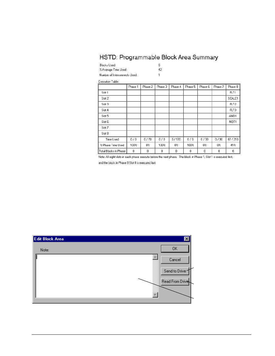
G-48
••••
Chapter 4 Configuring an AC & DC Version 2 Drive
Esay-Drive for AC & DC Version 2 Drive
! To view a summary of the block area
The Summary includes the
execution table showing the
exact order in which the
blocks will be executed, as
well as other statistics.
" Select either the BLKSTART or BLOCKEND item within the Programmable
Block Area. A summary of the block area displays in the right pane.
Uploading and Downloading Block Area
The drive must be online with
the Easy-Drive to upload or
download.
The Programmable Block Area is automatically uploaded and downloaded with the
drive parameters. The block area can also be uploaded or downloaded separately.
! To upload or download the block area
Or double-click on
Programmable Block Area.
1.
From the Outline View, click on the
Programmable Block Area item
2.
From the Edit menu, select Modify. The
Edit Block Area dialog box displays.
Notes entered here appear at
the top of the Block Flow View
Click to download the Block
Area to the drive.
Click to upload the active
Block Area from the drive.
If there are any Validation errors or warnings, they will display immediately.
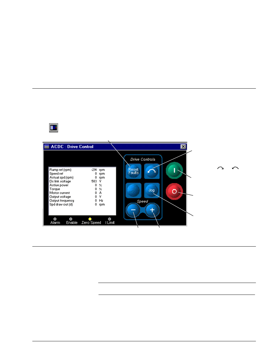
GEH-6412A Easy-Drive for Ac & DC Version 2 Drive
Chapter 4 Configuring an AC & DC Version 2 Drive
••••
G-49
Printing Block Area
! To print a block area
1. From the Outline View, click on the Programmable Block Area or any of its
sub-items.
2. From the File menu, select Print (for a hardcopy) and Print Preview (to view
on your display). The summary of the block area's execution order and the block
diagram are sent to printer or displayed on your screen.
Drive Controls
The Drive Control command enables you to operate the drive from the Easy-Drive,
as though you were operating it directly from the keypad located on the cabinet door.
The variables that display are the same as those that display on the keypad.
Or click
! To display the Drive Control view
"
From the View menu, select Drive Control. The Drive Control displays.
Click to toggle the
direction of the drive
(reverse resquest). The
selected direction is shown
with an icon or .
Click to reset faults.
Click to Run the drive in
the selected direction.
Stop command can be
used in Local or Remote
mode.
Click to decrease or increase the Local Speed Reference
associated with the Run and Stop commands.
Click to Jog the drive
forward.
Wizards
The Wizard list may vary with
each product, but there is
always an Offline Basic
Commissioning Wizard.
The AC & DC Version 2 drive contains wizards that guide you through the setup of
a drive. Wizards display a series of dialog boxes that prompt you for drive
configuration information. This information is also used as a basis to perform
additional tests and tune-ups on the drive.
Note When setting up a new drive, your first step should be to proceed through the
Offline Basic Commissioning Wizard or Offline Advanced Commissioning Wizard.
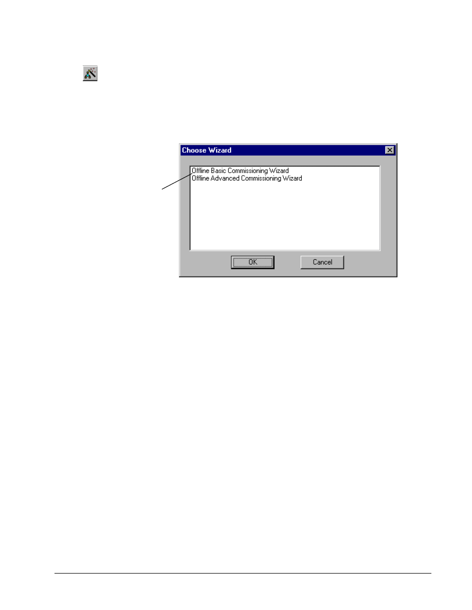
G-50
••••
Chapter 4 Configuring an AC & DC Version 2 Drive
Esay-Drive for AC & DC Version 2 Drive
! To perform a wizard
Or click
"
From the Edit menu, select
Wizards. If more than one wizard is defined, the Choose Wizard dialog
displays listing the available wizards. However, if only one wizard is defined,
the initial Offline Wizard dialog box displays immediately. (Refer to the next
section, Choose a Wizard.)
Choose a Wizard
Select the appropriate
wizard and click OK.
The wizard dialog box
displays.
The following are examples of the Offline Basic Commissioning Wizard.
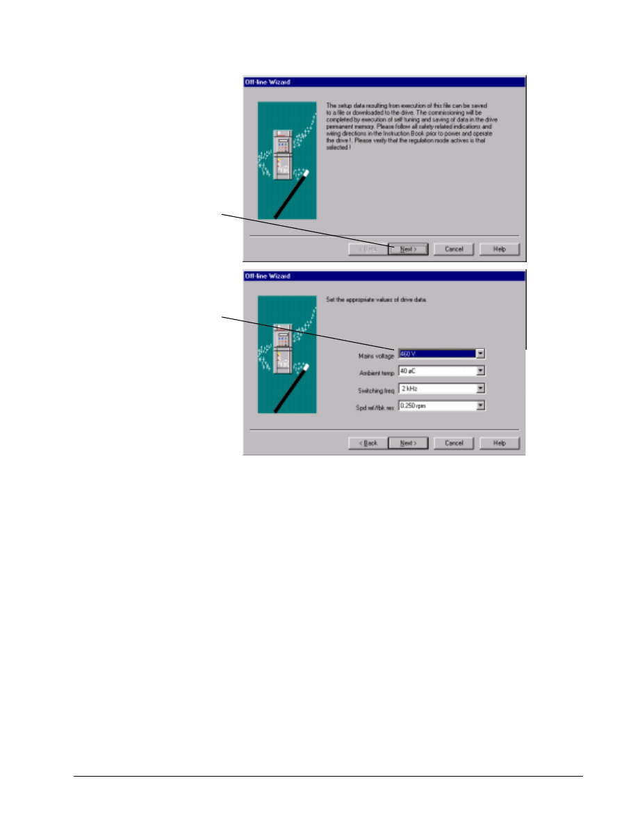
GEH-6412A Easy-Drive for Ac & DC Version 2 Drive
Chapter 4 Configuring an AC & DC Version 2 Drive
••••
G-51
Click to advance
through the wizard.
Click Help to display
interactive help on
each field.
Enter values in fields
unless otherwise
instructed.
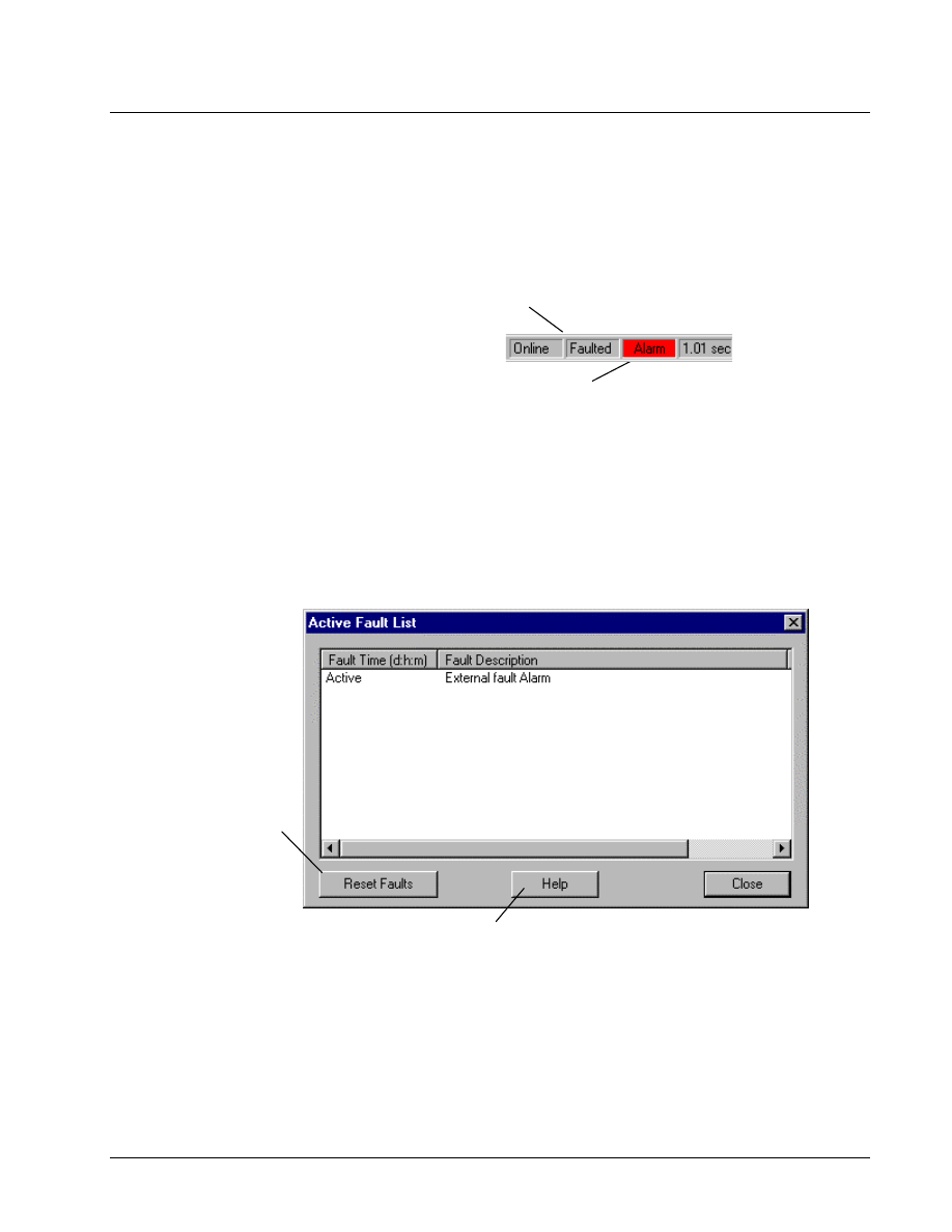
G-52
••••
Chapter 4 Configuring an AC & DC Version 2 Drive
Esay-Drive for AC & DC Version 2 Drive
Fault Display
The Easy-Drive can display two types of fault lists:
•
Active Fault list displays faults that are currently active in the drive.
•
Fault History list displays a list of faults that have cumulated since
power was applied to the drive.
The fault displays in red.
Double-click on the fault to
display the Active Fault list.
The Status bar, located at the bottom of the
screen, indicates that a fault has occurred.
Active Fault
! To display the Active Fault list
"
From the View menu, select Active Faults.
– Or –
"
Double-click on the Alarm on the Status bar. The Active Fault List
dialog box displays.
Click to reset the
fault list.
Check to display a description
of the selected fault.
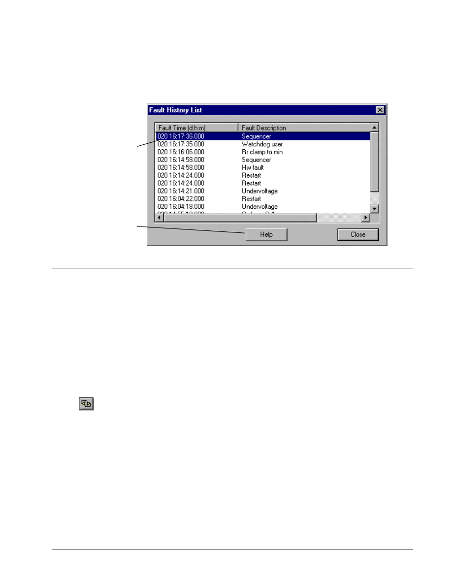
GEH-6412A Easy-Drive for Ac & DC Version 2 Drive
Chapter 4 Configuring an AC & DC Version 2 Drive
••••
G-53
Fault History
! To display the Fault History list
"
From the View menu, select Fault History. The Fault History List
dialog box displays.
This list is stored in
the drive.
A list of faults that
have cumulated
since power was
applied to the drive
displays. The most
recent fault appears
at the top.
Click to display a
description of the
selected fault.
Self-Tune
Self-tune is a process where the drive and the motor perform predefined tests to
determine the best running conditions for the system. There are two types of
self-tunes that are supported: Current Regulator and Speed Regulator.
Self-tune the Current Regulator
! To self-tune the current regulator on a drive
Or click
1. Create or open an AC & DC Version 2 drive (see the section, Creating an AC
& DC Version 2 Drive).
2. From the Device menu, select Online.
3. From the Device menu, select Self-Tune, and then select Current
Regulator.
Before the current Regulator can be tuned, the drive must be restarted in the Setup
mode. Once the drive is in the Setup mode, the Motor and Drive data that is
contained in the Easy-Drive configuration file is sent to the drive.
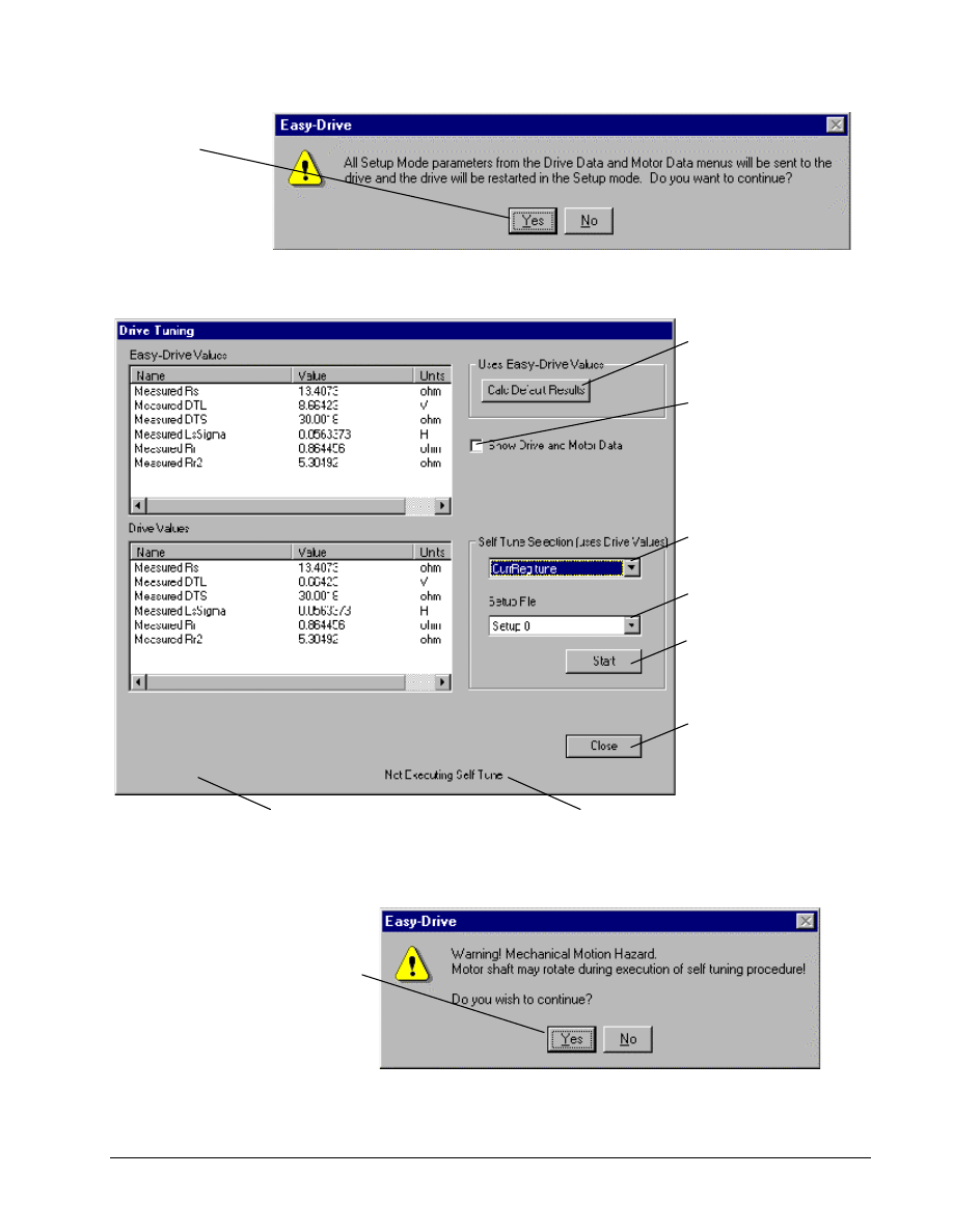
G-54
••••
Chapter 4 Configuring an AC & DC Version 2 Drive
Esay-Drive for AC & DC Version 2 Drive
Click Yes.
The drive is restarted
in Setup mode and
the Drive Tuning
dialog box displays.
Select the desired self-tune
from the drop-down list.
Displays the state of the
self-tune displays.
Click to start the self-tune
test process.
Click to complete the
self-tune process.
Displays any problems that
encountered during the self-tune
Check to display the Drive
Motor and Drive data.
Click to send the Easy-Drive
values to the drive and
calculate the default
starting values for
self-tuning.
Select the setup file where
the self-tune results will be
saved.
If you receive this warning
message box when you click
Start, click Yes to continue.
The Executing Self Tune
progress box displays.
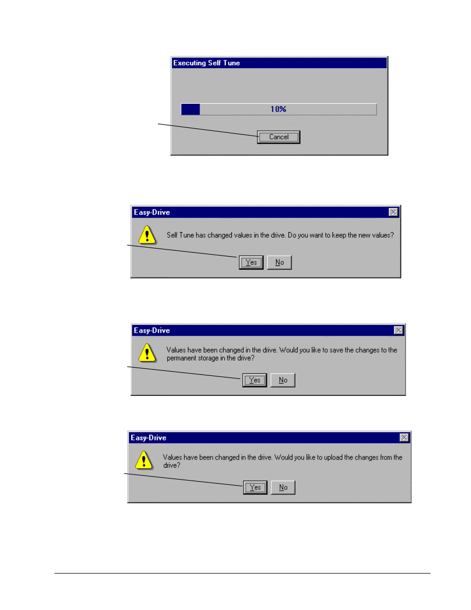
GEH-6412A Easy-Drive for Ac & DC Version 2 Drive
Chapter 4 Configuring an AC & DC Version 2 Drive
••••
G-55
Click to abort the
Self-Tune process.
When tuning is complete, click Close to complete the operation.
If values have changed in the drive, the following dialog box displays, prompting you to
save the new values.
A normal current
tune operation would
include both the
Current Regulator
tune-up and a Flux
Regulator tune-up.
Click to save the
new values.
The Save operation is performed and the drive is restarted in the regulation mode.
Click to save the
new values
permanently.
With one more message box, you are prompted to upload
the changes to configuration file loaded in the Easy-Drive.
Click to upload
the changes.
Another message box displays, prompting you to save the
values to a permanent non-volatile storage in the drive.
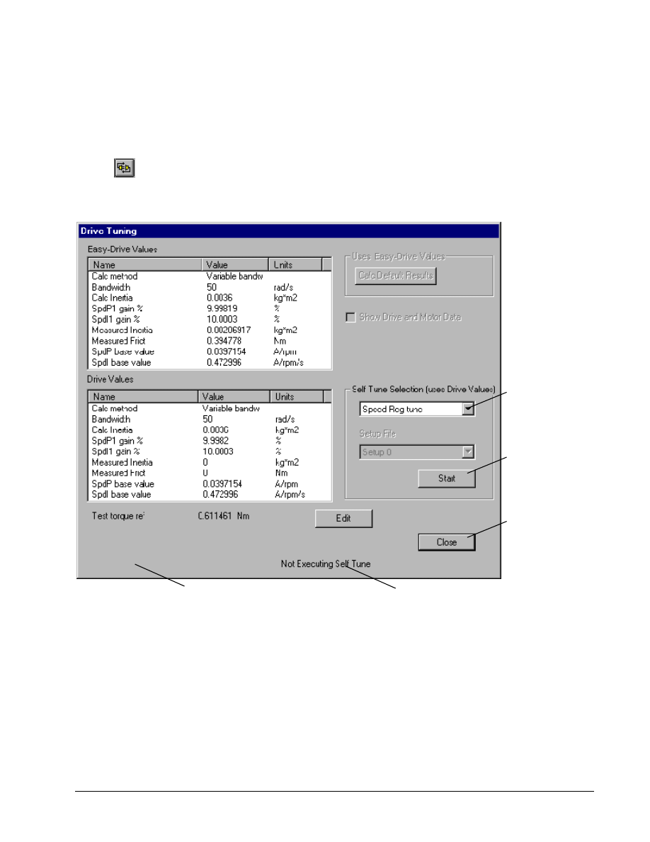
G-56
••••
Chapter 4 Configuring an AC & DC Version 2 Drive
Esay-Drive for AC & DC Version 2 Drive
Self-tune the Speed Regulator
The speed regulator is tuned up in the active regulation mode.
Or click
! To self-tune the speed regulator on a drive
1. Create or open an AC & DC Version 2 drive (see the section, Creating an AC
& DC Version 2 Drive).
2. From the Device menu, select Online.
3. From the Device menu, select Self-Tune, and then select Speed Regulator.
The Drive Tuning dialog box displays.
Select the desired
self-tune from the
drop-down list.
Displays the state of the
self-tune displays.
Click to start the
self-tune test
process.
Click to end the
process.
As the self-tune progresses,
messages may display
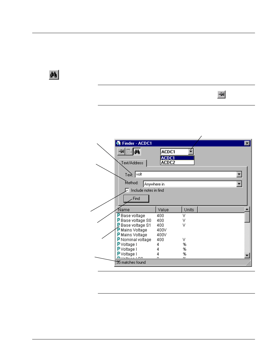
GEH-6412A Easy-Drive for Ac & DC Version 2 Drive
Chapter 4 Configuring an AC & DC Version 2 Drive
••••
G-57
Using the Finder
The Finder is a separate window in the Easy-Drive that contains useful search tools.
It can help you find items, such as text and variables from the different types of
drives.
! To use the Finder
Or click
" From the View menu, select Finder. The Finder dialog box
displays
.
Tip
$
By default, the Finder closes when the Find button is clicked or when you
click on any part of the screen outside the Finder Window. Click
to keep the
Finder open
.
Finder Window
Enter the text to find. (wildcards such
as * and ? are not supported). the
drop-down list box allows you to
access previous finds.
Method allows you to qualify the find
by choosing one of the following from
the drop-down box:
Anywhere In matches items that
contain the find text anywhere within
their text.
Begins with matches items whose
text begins with the find text.
Exact matches items whose text is
exactly as the find text.
Click here to include all note
message boxes in the find.
Click the Find button to start the
find.
All text that is found displays in the
Output View.
Status bar provides information about
the find operation.
Choose a target from the drop-down Target List. (All loaded
targets are listed. The default target is the current device.)
Note The Finder target determines the drive and area of the search. When Finder
is activated, the current drive is automatically chosen as the target and its name
displays in the Title bar. An AC & DC Version 2 drive target can find parameters
and variables.
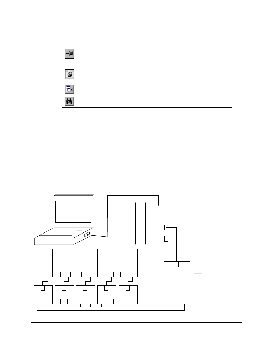
G-58
••••
Chapter 4 Configuring an AC & DC Version 2 Drive
Esay-Drive for AC & DC Version 2 Drive
Located below the Title bar is the toolbar, as described below:
Click…
To…
Hold the Finder Window open. If this button is displayed in the window, the Window
closes when the area outside the Finder Window is clicked. Click on the pushpin to
keep the Finder on top of the Device Window, even when you click outside the
Finder Window.
Close the Finder Window. This button is displayed when the pushpin above is
clicked on. The Finder Window remains opens when the pushpin is in this position
(even when working in another window).
Goto an item in the Outline View. Highlight an item in the Output View, then click
this button to find it in the Outline View. Double-click on the item to edit it.
Hide the tabs and make the Finder window display only the Output View.
ISBus Configuration
The ISBus provides a
high-speed connection
between drives and
controllers for both
synchronous and
asynchronous data.
This section describes how to insert the ISBus Interface (option card ISBus) for AC
& DC Version 2 drives and assign the data, which is to be exchanged. The ISBus is
commonly used to coordinate a set of drives with a controller. Physically, it is a ring
topology.
Communication is through a master/slave arrangement, where only the master can
communicate with a slave. Each bus can have only one master node. Depending on
the hardware platform, up to four ISBuses can be connected to a controller, with
letters A to D distinguishing each bus. The ISBus is also used to send asynchronous
data from the Easy-Drive to the drive. This feature supports the upload and
download of parameters and trending over an Ethernet connection through the
controller to drives on the ISBus. The following diagram shows a typical connection.
Ethernet to
Innovation Series
Controller using
the Easy Drive
Innovation
Series
Controller
ACDC
Drive
with ISBus
option
ISBus A
ISBus B
ISB1
RxTx
Tx
Note This ISBus setup,
using bypass modules,
allow drives to be shut off
and maintain the ISBus
ring and functions.
ISBus bypass
P2
P2
P2
P2
P2
P3
P3
P3
P3
P3
P1
P1
P1
P1
P1
ACDC
Drive
with ISBus
option
ISBus bypass
ISBus bypass
ISBus bypass
ISBus bypass
Ethernet
RxTx
Tx
RxTx
Tx
RxTx
Tx
RxTx
Tx
ISBus
splitter
module
*
Tx
RxTx
P1
P3
P2
ACDC
Drive
ACDC
Drive
ACDC
Drive
with ISBus
with ISBus
with ISBus
option
option
option
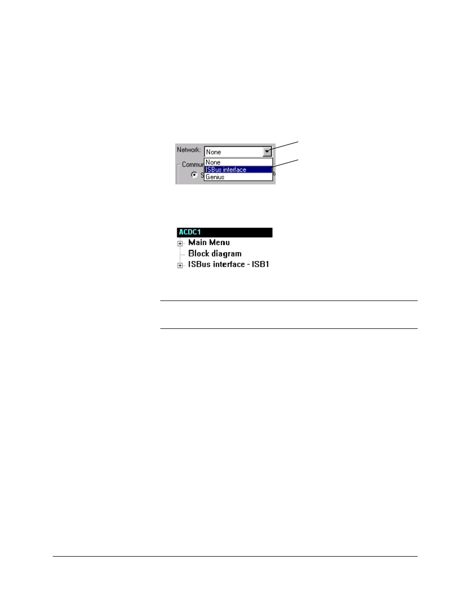
GEH-6412A Easy-Drive for Ac & DC Version 2 Drive
Chapter 4 Configuring an AC & DC Version 2 Drive
••••
G-59
Adding an ISBus to Configuration
! To insert an ISBus
Or click the right mouse
button and select Modify.
1. From the Outline View, click on
the drive name.
2. From the Edit menu, select
Modify. The Edit Device
Properties dialog box displays.
Click to display the
drop-down menu.
Select ISBus interface.
3. Click OK. The ISBus interface
item displays at the bottom of the
listed items in the Outline View.
4. The default ISBus mapping and setup are loaded. Mapping and descriptions can
be changed, saved, and supported.
Note Once the ISBus has been configured, use the drive parameter ISBUS Enable
to enable and disable the option. Cycling the ISBus selection will re-initialize the
ISBus.
Editing an ISBus
! To edit an ISBus
Or click the right mouse
button and select Modify.
1. From the Outline View, click on the ISBus interface item.
2. From the Edit menu, select Modify. The Network Interface dialog box
displays.
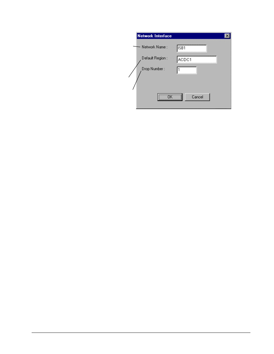
G-60
••••
Chapter 4 Configuring an AC & DC Version 2 Drive
Esay-Drive for AC & DC Version 2 Drive
Change any of the fields:
Network Name is assigned when a network
is inserted using the Easy-Drive. This name is
used to identify the network to which
devices are connected in the system. This
information is posted into the SDB and is
used to interconnect the system.
Default Region is usually the name of the
drive.
Drop Number is the ISBus node number for
this device. Valid entries are from 1-31.
Click OK.

GEH-6412A Easy-Drive for Ac & DC Version 2 Drive
Chapter 4 Configuring an AC & DC Version 2 Drive
••••
G-61
ISBus Pages
Pages provide a way to share live signals over the ISBus. Pages are defined in the
drive and their definition is published to the controller through the SDB. The drive
has a set of pages with a default signal layout and define commonly used signals.
The individual pages can be customized to change the signals, which are exchanged
between the drive and the controller. For the AC&DC Version 2 drive, the maximum
size of a page is 16 bytes, organized as eight 16-bit words. Booleans are transferred
as single bits. They are defined using a bit number word number notation, where the
word number ranges from 1–7, and the bit number ranges from 0–15.
Setting References from ISBus to Drive
! To set a reference to be controlled from the ISBus
Refer to the section, Using the
Finder.
Or click the right mouse
button and select Modify.
Refer to the section, Editing
Parameters.
1. Using the Finder, locate the parameter that you want controlled from the ISBus
(for example, Ramp ref 1 src). Then click the Goto button to display the
parameter location in the Outline View.
2. Click on the parameter name. From the Edit menu, select Modify. The Edit
Parameter dialog box displays.
3. From the Value drop-down list, select the appropriate value for the ISBus
interface (using the example above, ISBus Drv W1 mon). The Ramp Ref 1 src
is controlled from the ISBus.
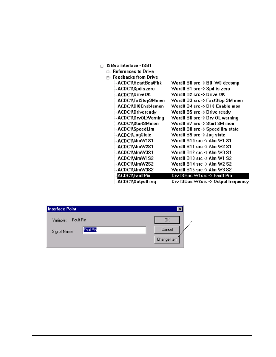
G-62
••••
Chapter 4 Configuring an AC & DC Version 2 Drive
Esay-Drive for AC & DC Version 2 Drive
Feedbacks from Drive to the ISBus
! To set a feedback variable
Or click the right mouse
button and select Modify.
1. From the Outline View, click on the desired item (for example, Drv ISBus
W1src).
2. Click on the item name. From the Edit menu, select Modify. The Interface
Point dialog box displays.
Click to display the
Edit Parameter dialog
box, from where you
can choose another
signal.
This signal name can
also be customized.
If any changes to the map are made, you will be prompted to update the SDB.
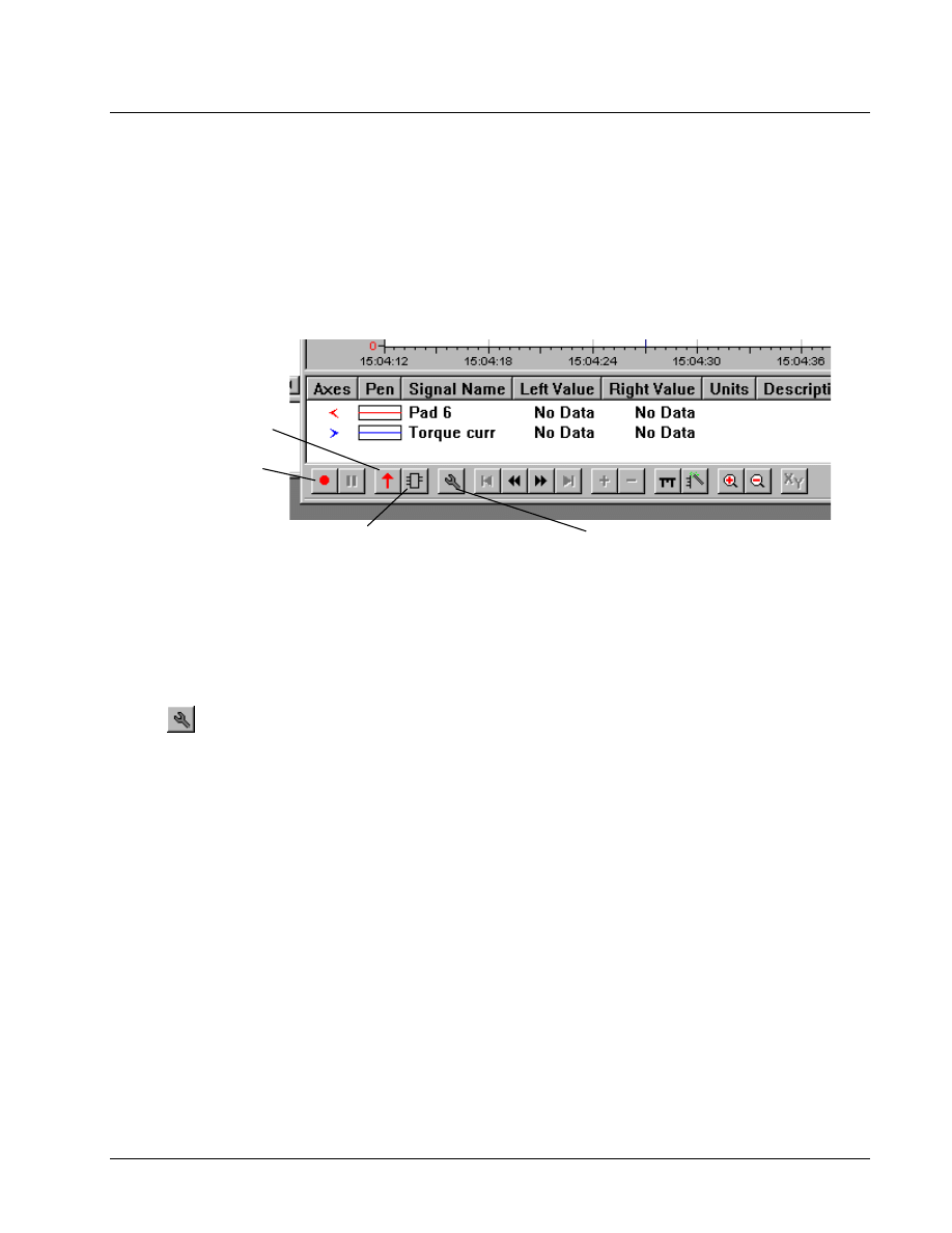
GEH-6412A Easy-Drive for Ac & DC Version 2 Drive
Chapter 4 Configuring an AC & DC Version 2 Drive
••••
G-63
AC & DC Version 2 Capture Buffer
The rate of samples per
channel depends on the
number of channels.
Configuring two channels,
results in a rate of 2048
samples per channel; while
four channels results in a rate
of 1024 samples per channel.
The AC & DC Version 2 drive has a capture buffer that allows up to 4 channels of
data to be collected at sample rates as high as 1 ms. The drive collects a total of 4096
samples. This capture buffer can be used with the Trend Recorder to diagnose
problems that require higher sample rates than the Trend Recorder's Real Time mode
can collect.
In Block Collected mode, there are several toolbar buttons used to configure and
operate the Capture Block.
Capture Enable
enables the
Trigger input.
Upload Data
retrieves captured
data.
Edit Capture Block displays a dialog that allows
you to select input signals and the trigger for the
capture block, as well as the sample rate.
Configure allows you to select
realtime capture or capture block
operation and enable auto-upload.
Capturing Data Block
! To enter Block Collected mode in Trend Recorder
Or click
1. Open a new Trend Recorder session.
2. From the Edit menu, select Configure.
The Trend Recorder Configuration
dialog box displays.
3. Click the Block Collected tab.
4. Verify the correct device is selected in the
Block Collector Device section. If not,
click Change and select the desired device
from the Select Device Containing
Block Collector dialog box.
5. If desired, check the Automatically
upload captured data option.
6. Click OK. The Capture Block Setup
dialog box displays (for more information,
refer to the next section, Configuring the
Capture Block).
Configuring the Capture Block
Before you can use the Capture Block, you must first configure the block.
! To configure the Capture Block
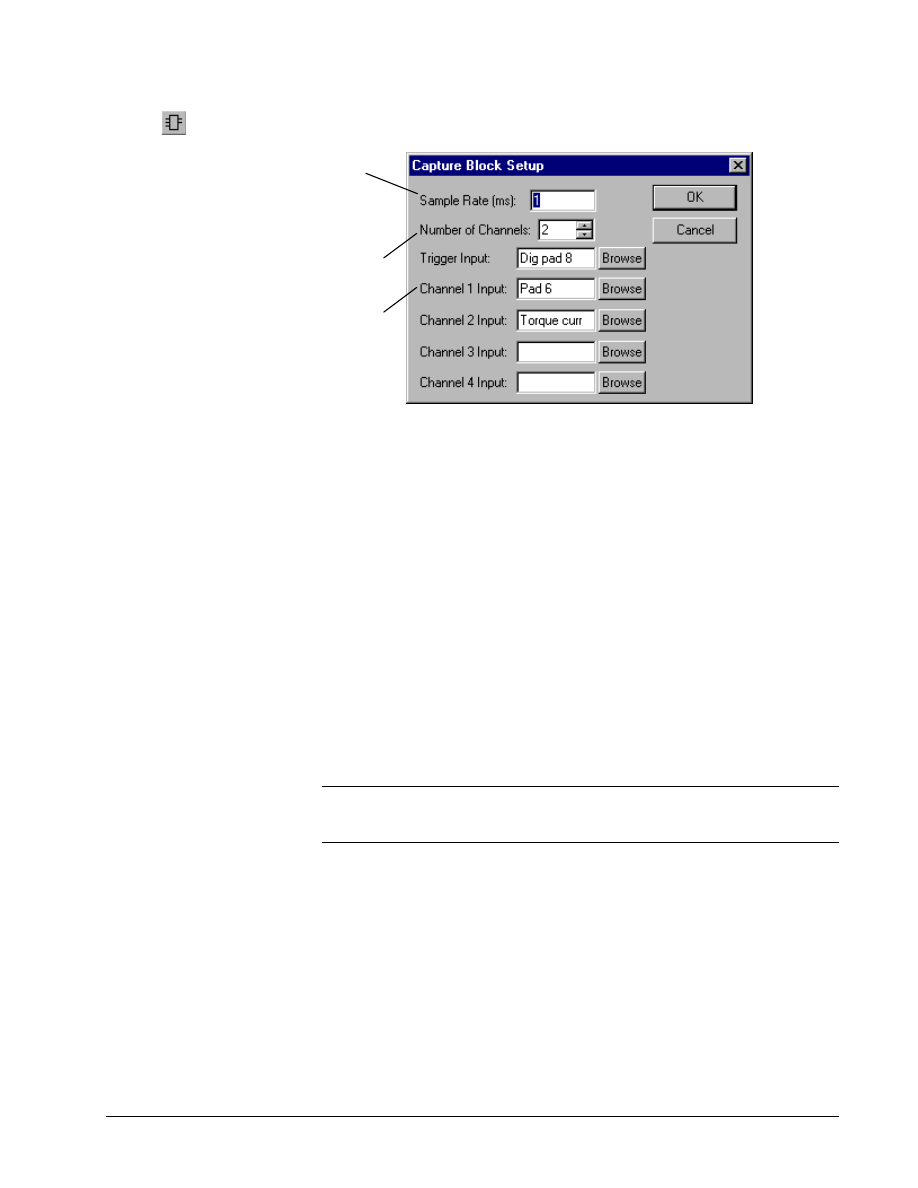
G-64
••••
Chapter 4 Configuring an AC & DC Version 2 Drive
Esay-Drive for AC & DC Version 2 Drive
Or click
" Within the Capture Block Setup dialog box, enter the desired values in the
appropriate fields.
Sample Rate controls how
often the capture block
samples the input signals (in
milliseconds). It must be a
positive integer.
Enter the name of any variable
or parameter. Or click Browse
to search for a variable.
Select the number of channels to
capture (0 - 4).
When done, click OK.
The new Capture Block Setup
is sent to the drive.
! To edit the Capture Block configuration
"
From the Edit menu, select Edit Block. The Capture Block Setup
dialog box displays.
All variables and parameters that are valid for the current regulation mode can be
used as capture inputs or as the trigger. Typical trigger sources include Fault
monitors, digital inputs, and pad parameters driven by Programmable Block Area
functions.
Once the Capture Block has been configured, if the AC & DC Version 2 drive is
online, the Enable Capture button will be enabled. Click this button to allow the
Trigger signal to activate data collection. When the button is in the down, or pressed,
position, the trigger is active. When the signal attached to the trigger goes from zero
to one (or non-zero), the data collection begins. When the capture block runs out of
space, the data collection will end and the Enable Capture button will return to the
up position. If the Automatically upload captured data option is enabled, the
capture buffer will then automatically upload the collected data. The data can also be
uploaded manually by clicking Upload.
Note When the Enable Capture button is pressed, the capture buffer will remain
enabled even if you close the Trend Recorder. This is useful for recording drive data
using an event, such as a fault, that occurs infrequently to trigger the collection.
The Upload process can take as long as five minutes to complete. To view a partial
load, you can select Cancel. The data values are displayed in the default units for
their variable or parameter.

GEH-6412A Easy-Drive for Ac & DC Version 2 Drive
Glossary of Terms
••••
G-65
Glossary of Terms
AcDcEx2000
Refers to the dc drives (DC2000), ac drives (AC2000), and exciters (EX2000), which
are all referenced in the combined device type name. These three devices can use the
same application control boards and devices in the Easy-Drive.
ACL controller
Application Control Layer controller. A form of the Innovation Series controller
hosted in the Innovation Series drive rack that performs job specific, outer layer,
drive control loops and sequencing.
application code
Software that controls specific machines or processes.
ASCII
American Standard Code for Information Interchange. An 8-bit code used for data.
attributes
Information, such as location, visibility, and type of data that sets something apart
from others. In signals, an attribute can be a field within a record.
automatically named signals
Signals that are created as a result of inserting some instruction block(s) other than a
Signal Definition. One or more regions of such signals is of the form }00123.
baud
A unit of data transmission. Baud rate is the number of bits per second transmitted.
bind
The act of retrieving configuration information from some system database.
BIOS
Basic input/output system. Performs the boot-up, which includes hardware self-tests
and the file system loader. The BIOS is stored in EEPROM and is not loaded from
the Easy-Drive.
bit
Binary Digit. The smallest unit of memory used to store only one piece of
information with two states, such as One/Zero or On/Off. Data requiring more than
two states, such as numerical values 000 to 999, requires multiple bits (see Word).

G-66
••••
Glossary of Terms
Esay-Drive for AC & DC Version 2 Drive
block
Instruction blocks contain basic control functions, which are connected together
during configuration to form the required machine or process control. Blocks can
perform math computations, sequencing, or continuous control. The Easy-Drive
receives a description of the blocks from the block libraries.
board
Printed wiring board.
Boolean
Digital statement that expresses a condition that is either True or False. In the Easy-
Drive, it is a data type for logical signals.
bus
An electrical path for transmitting and receiving data.
bumpless
No disrupt to the control when downloading.
byte
A group of eight binary digits (bits) operated on a single unit.
CMOS
Complementary metal-oxide semiconductor.
collection
A group of signals found on the same network. The Trend Recorder can be
configured by adding collections.
COM port
Serial controller communication ports (two). COM1 is reserved for diagnostic
information and the Serial Loader. COM2 is used for I/O communication
configure
To select specific options, either by setting the location of hardware jumpers or
loading software parameters into memory.
datagrams
Messages sent from the controller to I/O blocks over the Genius network.

GEH-6412A Easy-Drive for Ac & DC Version 2 Drive
Glossary of Terms
••••
G-67
dead band
A range of values in which the incoming signal can be altered without changing the
outgoing response.
device
A configurable component of a process control system.
Drive Control
Enables you to control the drive from the Easy-Drive application.
Easy-Drive
A Windows-based software package used to configure drives.
Ethernet
LAN with a 10/100 MB baud collision avoidance/collision detection system used to
link one or more computers together. Basis for TCP/IP and I/O services layers that
conforms to the IEEE 802.3 standard, developed by Xerox, Digital, and Intel.
fault code
A message from the controller to the HMI indicating a controller warning or failure.
Finder
A subsystem of the Easy-Drive for searching and determining the usage of a
particular item in a configuration.
firmware
The set of executable software that is stored in memory chips that hold their content
without electrical power, such as EEPROM.
flash
A non-volatile programmable memory device.
font
One complete collection of letters, punctuation marks, numbers, and special
characters with a consistent and identifiable typeface, weight, posture, and size.
forcing
Setting a live signal to a particular value, regardless of the value blockware or I/O is
writing to that signal.
function
The highest level of the blockware hierarchy and the entity that corresponds to a
single .tre file.
gateway
A device that connects two dissimilar LAN or connects a LAN to a wide-area
network (WAN), PC, or a mainframe. A gateway can perform protocol and
bandwidth conversion.

G-68
••••
Glossary of Terms
Esay-Drive for AC & DC Version 2 Drive
Graphic Window
A subsystem of the Easy-Drive for viewing and setting the value of live signals.
groups
See Resources.
health
A term that defines whether a signal is functioning as expected.
heartbeat
A signal emitted at regular intervals by software to demonstrate that it is still active.
hexadecimal (hex)
Base 16 numbering system using the digits 0-9 and letters A-F to represent the
decimal numbers 0-15. Two hex digits represent 1 byte.
initialize
To set values (addresses, counters, registers, and such) to a beginning value prior to
the rest of processing.
I/O
Input/output interfaces that allow the flow of data into and out of a device.
I/O drivers
Interface the controller with input/output devices, such as sensors, solenoid valves,
and drives, using a choice of communication networks.
I/O mapping
Method for moving I/O points from one network type to another without needing an
interposing application task.
insert
Adding an item either below or next to another item in a configuration, as it is
viewed in the hierarchy of the Outline View of the Easy-Drive.
instance
Update an item with a new definition.
item
A line of the hierarchy of the Outline View of the Easy-Drive, which can be inserted,
configured, and edited (such as Function or System Data).
logical
A statement of a true sense, such as a Boolean.
macro
A group of instruction blocks (and other macros) used to perform part of an
application program. Macros can be saved and reused.

GEH-6412A Easy-Drive for Ac & DC Version 2 Drive
Glossary of Terms
••••
G-69
model
Interactive setup data (recipe) that automatically adjusts to the process. This function
is usually used with hot mills or cold mills.
module
A collection of tasks that have a defined scheduling period.
non-volatile
The memory specially designed to store information even when the power is off.
online
Online mode provides full CPU communications, allowing data to be both read and
written. It is the state of the Easy-Drive when it is communicating with the system
for which it holds the configuration. Also, a download mode where the device is not
stopped and then restarted.
pcode
A binary set of records created by the Easy-Drive, which contain the controller
application configuration code for a device. Pcode is stored in RAM and Flash
memory.
period
The time between execution scans for a Module or Task. Also a property of a
Module that is the base period of all of the Tasks in the Module.
period multiplier
A property of a Task that permits the Task’s execution rate to be a multiple of its
Modules period.
physical
Refers to devices at the electronic or machine level in contrast with logical. Logical
implies a higher view than the physical. Users relate to data logically by data element
name; however, the actual fields of data are physically located in sectors on a disk.
pin
Block, macro, or module parameter that creates a signal used to make
interconnections.
PLC
Programmable Logic Controller. Designed for discrete (logic) control of machinery.
It also computes math (analog) function and performs regulatory control.
product code (runtime)
Software stored in the controller’s Flash memory that interrupts the application
configuration and performs the requested activities. This includes code such as I/O
drivers and control block libraries.
put into database
Command in the Device menu used to add configuration information into a system
database.

G-70
••••
Glossary of Terms
Esay-Drive for AC & DC Version 2 Drive
realtime
Immediate response. It refers to process control and embedded systems, and fast
transaction processing systems that must respond instantly to changing conditions.
reboot
To restart the Easy-Drive.
recipe
Information for process line or paper mill that provides setup data, such as speed,
length, and tension.
register page
A form of shared memory that is updated over a network. Register pages can be
created and instanced in the controller and posted to the SDB.
relay ladder diagram (RLD)
A ladder diagram has a symbolic power source. Power is considered to flow from the
left rail through a contact to the coil connected to the right.
Resources
Also known as groups. Resources are systems (devices, machines, or work stations
where work is performed) or areas where several tasks are carried out. Resource
configuration plays an important role in the CIMPLICITY system by routing alarms
to specific users and filtering the data users receive.
runtime
See product code.
runtime errors
controller problems indicated on the front panel by coded flashing LEDS and also in
the Log View of the Easy-Drive.
sample set
Set of values taken when signals are being trended together with the Trend Recorder.
sampling rate
The period that values are collected to put in a sample set.
Serial Loader
Connects the controller to the Easy-Drive PC using the RS-232C COM ports. The
Serial Loader initializes the controller flash file system and sets its TCP/IP address to
allow it to communicate with the Easy-Drive over Ethernet.
service
Functionality derived from a particular software program. For example, the Recorder
Service transmits and provides conversion of data in the SDB.
signal
The basic unit for variable information. Signals are the placeholders for memory
locations in the Easy-Drive’s different platforms.

GEH-6412A Easy-Drive for Ac & DC Version 2 Drive
Glossary of Terms
••••
G-71
simulation
Running a system without all of the configured I/O devices by modeling the behavior
of those devices in software.
skew
A property of modules that allows a module to execute at a different time slice than
other modules with the same period.
skew offset
A property of tasks that allows a task to execute at a different time slice than other
tasks within the same module.
symbols
Created by the Easy-Drive and stored in the controller, the symbol table contains
signal names and descriptions for diagnostic messages.
task
A group of blocks and macros scheduled for execution by the user.
TCP/IP
Communications protocols developed to inter-network dissimilar systems. It is a de
facto UNIX standard, but is supported on almost all systems. TCP controls data
transfer and IP provides the routing for functions, such as file transfer and e-mail.
time slice
Division of the total module scheduling period. There are eight slices per single
execution period. These slices provide a means for scheduling modules and tasks to
begin execution at different times.
trend
A time-based plot to show the history of values.
Trend Recorder
A subsystem of the Easy-Drive that monitors and graphs signal values from a
controller or drive.
TrueType
Scaleable font technology that renders printer and screen fonts. Each TrueType font
contains its own algorithms for converting the outline into bitmaps.
validate
Makes certain that items or devices do not contain errors and verifies that the
configuration is ready to be built into pcode.
Windows NT
Windows New Technology. Advanced 32-bit operating system from Microsoft for
386s and above. It runs NT-specific applications as well as those written for DOS,
Windows 3.x (16 and 32-bit), OS/2 character mode (non-graphical) and POSIX. NT
does not use DOS; it is a self-contained operating system.

G-72
••••
Glossary of Terms
Esay-Drive for AC & DC Version 2 Drive
word
A unit of information composed of characters, bits, or bytes, that is treated as an
entity and can be stored in one location. Also, a measurement of memory length,
usually 4, 8, or 16-bits long.

Easy-Drive for AV-300i Version 2 Drive
••••
I-1
Wyszukiwarka
Podobne podstrony:
10 Easy Steps to Turning Dreams into Reality!
drzwi czech e60 EASY 719 DC RC
Easy 07290100002
It's Easy to Earn Money
Easy Setup AP 604g
easy v2b
Easy reading in spanish la chica del tren
Labirynty Łatwe, new year maze easy
You drive me crazy
11 Easy Learning Polish
00090100087 ultra easy, 00090100087
A neural network based space vector PWM controller for a three level voltage fed inverter induction
zminy w rejestrze sem II, Linux, płyty dvd, inne dvd, 2, temp pend drive
Pro drive Quick Start
aaa pg cylinder head valve drive
Jouni Yrjola Easy Guide to the Classical Sicilian (feat Richter Rauzer and Sozin Attacks)
więcej podobnych podstron