Source:
Show Navigation |
You are here:
Data support in ArcGIS > Raster data > Designing a raster database
BIL, BIP, and BSQ raster files
Release 9.2
Last modified September 22, 2008
Print all topics in :
Related Topics
Supported raster dataset file formats
Band interleaved by line (BIL), band interleaved by pixel (BIP), and band sequential (BSQ) are three
common methods of organizing image data for multiband images. BIL, BIP, and BSQ are not in
themselves image formats but are schemes for storing the actual pixel values of an image in a file.
These files support the display of single and multiband images and handle black-and-white, grayscale,
pseudo color, true color, and multispectral image data.
The BIL, BIP, and BSQ files are binary files, and they must have an associated ASCII file header to be
interpreted properly by ArcGIS. This header file contains ancillary data about the image such as the
number of rows and columns in the image, if there is a color map, and latitude and longitude.
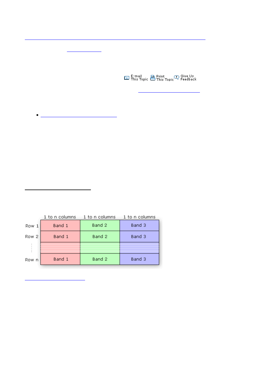
Band interleaved by line data stores pixel information band by band for each line, or row, of the
image. For example, given a three-band image, all three bands of data are written for row 1, all three
bands of data are written for row 2, and so on, until the total number of rows in the image is reached.
The following diagram illustrates BIL data for a three-band dataset:
The following is an example of the band interleaved by line (BIL) file format as it would be written for
the graphic below. An actual .bil file will be binary; however, for the purpose of this example it will be
shown using ascii characters.
RGBcomposite.bil
0 0 0 0 0 0 0 0 0 0 64 64 128 128 255 255 255 255 255 255 255 255 255 255
0 0 0 0 0 0 0 0 0 0 64 64 128 128 255 255 255 255 255 255 255 255 255 255
64 64 64 64 64 64 64 64 0 0 64 64 128 128 255 255 128 128 128 128 128 128 128 128
64 64 64 64 64 64 64 64 0 0 64 64 128 128 255 255 128 128 128 128 128 128 128 128
128 128 128 128 128 128 128 128 0 0 64 64 128 128 255 255 64 64 64 64 64 64 64 64
128 128 128 128 128 128 128 128 0 0 64 64 128 128 255 255 64 64 64 64 64 64 64 64
255 255 255 255 255 255 255 255 0 0 64 64 128 128 255 255 0 0 0 0 0 0 0 0
255 255 255 255 255 255 255 255 0 0 64 64 128 128 255 255 0 0 0 0 0 0 0 0
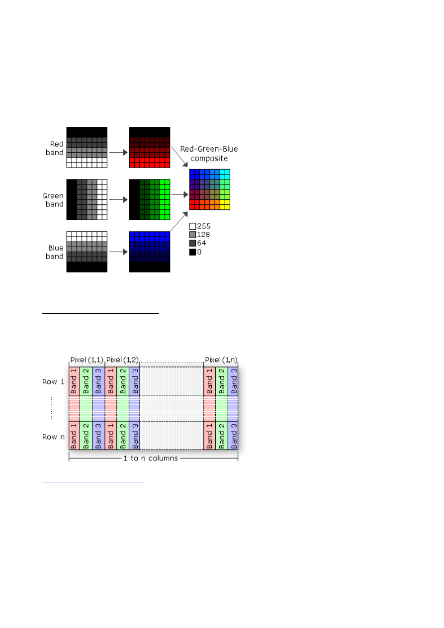
Band interleaved by pixel data is similar to BIL data, except that the data for each pixel is written
band by band. For example, with the same three-band image, the data for bands 1, 2, and 3 are written
for the first pixel in column 1; the data for bands 1, 2, and 3 are written for the first pixel in column 2;
and so on.
The following is an example of the band interleaved by pixel (BIP) file format as it would be written
for the graphic below. An actual .bip file will be binary; however, for the purpose of this example it
will be shown using ascii characters.
RGBcomposite.bip
0 0 255 0 0 255 0 64 255 0 64 255 0 128 255 0 128 255 0 255 255 0 255 255
0 0 255 0 0 255 0 64 255 0 64 255 0 128 255 0 128 255 0 255 255 0 255 255
64 0 128 64 0 128 64 64 128 64 64 128 64 128 128 64 128 128 64 255 128 64 288 128
64 0 128 64 0 128 64 64 128 64 64 128 64 128 128 64 128 128 64 255 128 64 288 128
128 0 64 128 0 64 128 64 64 128 64 64 128 128 64 128 128 64 128 255 64 128 255 64
128 0 64 128 0 64 128 64 64 128 64 64 128 128 64 128 128 64 128 255 64 128 255 64
255 0 0 255 0 0 255 64 0 255 64 0 255 128 0 255 128 0 255 255 0 255 255 0
255 0 0 255 0 0 255 64 0 255 64 0 255 128 0 255 128 0 255 255 0 255 255 0
Band sequential format stores information for the image one band at a time. In other words, data for
all the pixels for band 1 is stored first, then data for all pixels for band 2, and so on.
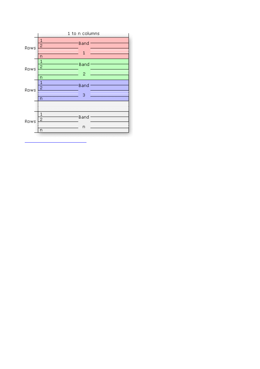
The following is an example of the band sequential (BSQ) file format as it would be written for the
graphic below. An actual .bsq file will be binary; however, for the purpose of this example it will be
shown using ascii characters.
RGBcomposite.bsq
0 0 0 0 0 0 0 0
0 0 0 0 0 0 0 0
64 64 64 64 64 64 64 64
64 64 64 64 64 64 64 64
128 128 128 128 128 128 128 128
128 128 128 128 128 128 128 128
255 255 255 255 255 255 255 255
255 255 255 255 255 255 255 255
0 0 64 64 128 128 255 255
0 0 64 64 128 128 255 255
0 0 64 64 128 128 255 255
0 0 64 64 128 128 255 255
0 0 64 64 128 128 255 255
0 0 64 64 128 128 255 255
0 0 64 64 128 128 255 255
0 0 64 64 128 128 255 255
255 255 255 255 255 255 255 255
255 255 255 255 255 255 255 255
128 128 128 128 128 128 128 128
128 128 128 128 128 128 128 128
64 64 64 64 64 64 64 64
64 64 64 64 64 64 64 64
0 0 0 0 0 0 0 0
0 0 0 0 0 0 0 0
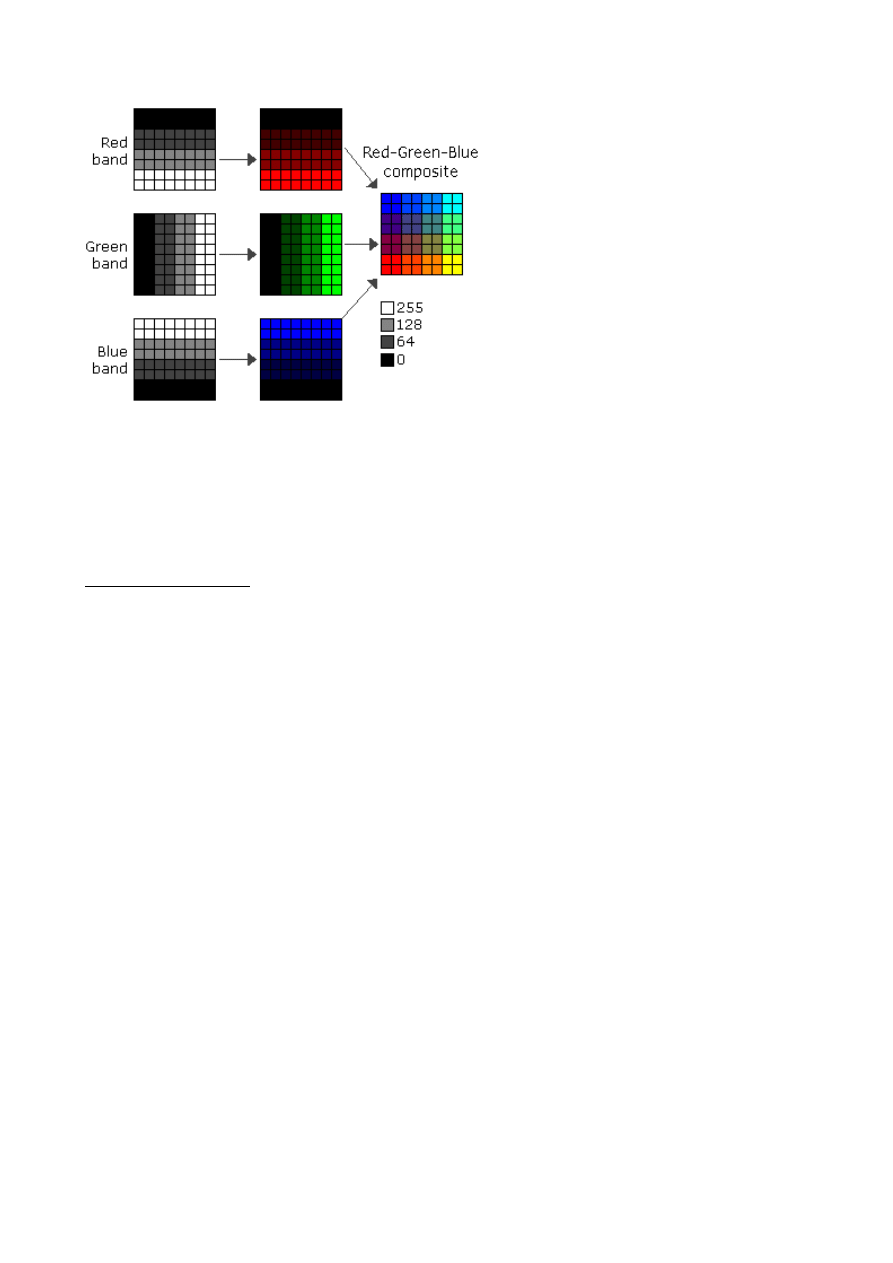
Image description files
There are three description files that can be provided with BIL, BIP, or BSQ files: a header file (hdr)
that describes the layout of the image pixel data and must be provided, a color file (clr) that describes
the image color map, and a statistics file (stx) that describes image statistics for each band of the
image. These ASCII text files can be generated in a text editor using the information you know about
the image.
The header file
The header file describes the image data. You must generate a header file for each image, and it should
have the same file name with a .hdr extension, for example:
<image>.hdr
The header file contains a set of entries, each of which describes a particular attribute of the image. For
example, an entry can describe the number of rows or columns in the image. The format of each entry
is
<keyword> <value>
in which <keyword> indicates the particular attribute that is being set, and <value> is the value to
which the attribute is being set. The entries in the header can be in any order, but each must be on a
separate line of the file. Any line in the file that does not begin with a keyword is treated as a comment

and ignored.
The following list identifies the valid keywords and describes the particular image attribute they
define. Several of the keywords have default values. Where the default value accurately represents the
image data, you can omit the keyword from the header file.
nrows—The number of rows in the image. Rows are parallel to the x-axis of the map coordinate
system. There is no default.
ncols—The number of columns in the image. Columns are parallel to the y-axis of the map coordinate
system. There is no default.
nbands—The number of spectral bands in the image. The default is 1.
nbits—The number of bits per pixel per band. Acceptable values are 1, 4, 8, 16, and 32. The default
value is 8 bits per pixel per band. For a true color image with three bands (R,G,B) stored using 8 bits
for each pixel in each band, nbits equals 8 and nbands equals 3 for a total of 24 bits per pixel. For an
image with nbits equal to 1, nbands must also equal 1.
byteorder—The byte order in which image pixel values are stored. The byte order is important for 16-
bit images with two bytes per pixel. Acceptable values are:
I—Intel byte order (Silicon Graphics, DEC Alpha, PC)—also known as little-endian
M—Motorola byte order (Sun, HP, etc.)—also known as big-endian
The default byte order is the same as that of the host machine executing the software.
layout—The organization of the bands in the image file. Acceptable values are:
bil—band interleaved by line. This is the default.
bip—band interleaved by pixel.
bsq—band sequential.
skipbytes—The number of bytes of data in the image file to skip to reach the start of the image data.
This keyword allows you to bypass any existing image header information in the file. The default
value is 0 bytes.
ulxmap—The x-axis map coordinate of the center of the upper left pixel. If you specify this parameter,
set ulymap, too; otherwise, a default value is used.
ulymap—The y-axis map coordinate of the center of the upper left pixel. If this parameter is specified,
ulxmap must also be set; otherwise, a default value is used.
xdim—The x-dimension of a pixel in map units. If this parameter is specified, ydim, ulxmap, and
ulymap must also be set; otherwise, a default value is used.
ydim—The y-dimension of a pixel in map units. If this parameter is specified, xdim, ulxmap, and
ulymap must also be set; otherwise, a default value is used.
The following figure shows the default values for ulxmap, ulymap, xdim, and ydim. The center of the
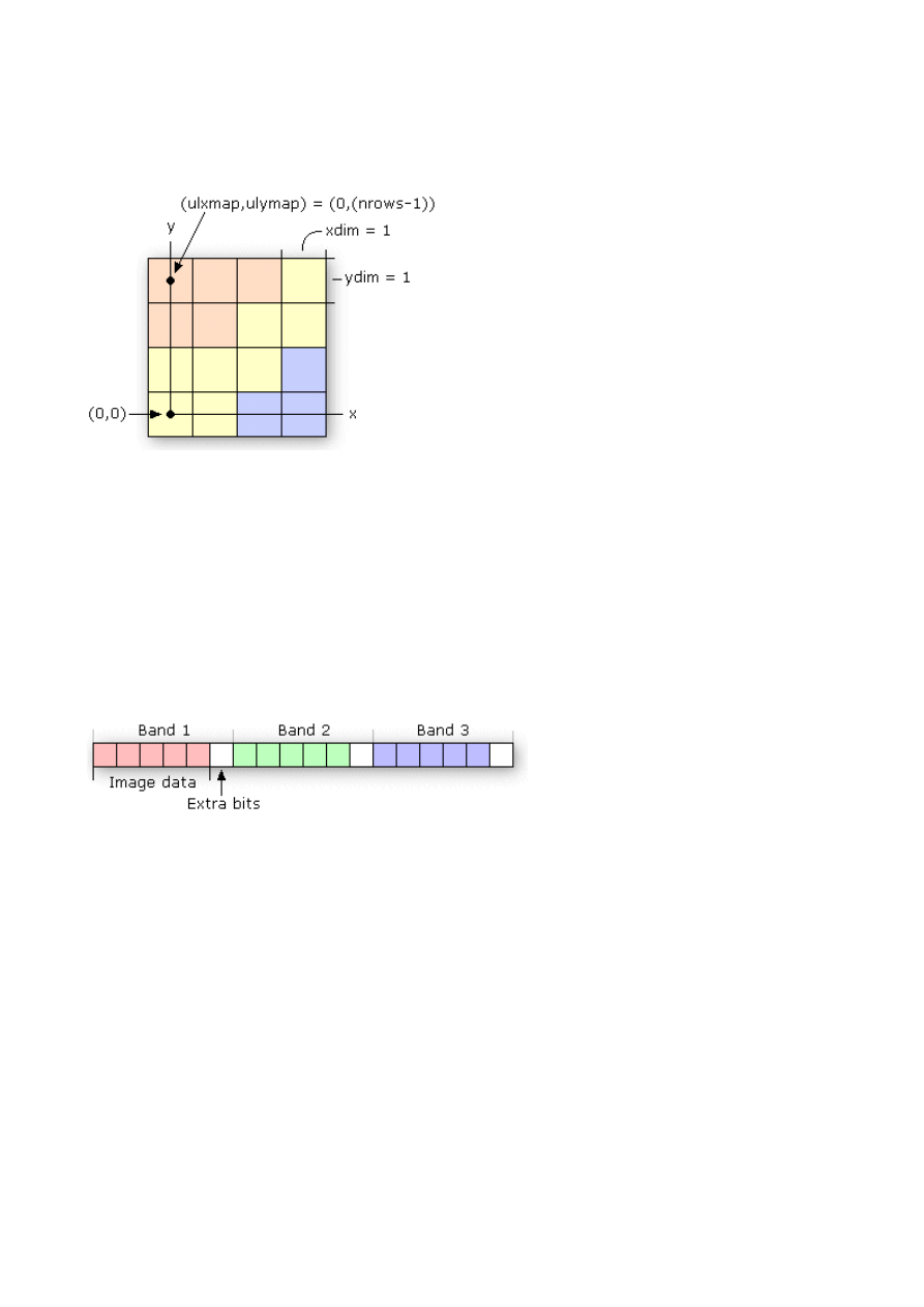
upper left pixel will have map coordinates (ulxmap, ulymap) = (0, (nrows - 1)), with the center of the
lower left pixel at (0, 0). In this figure, the coordinate value for ulxmap and ulymap is (0, 3). The x-
and y-pixel dimensions will default to xdim = 1 and ydim = 1.
bandrowbytes—The number of bytes per band per row. This must be an integer. This keyword is used
only with BIL files when there are extra bits at the end of each band within a row that must be skipped.
Bandrowbytes can be thought of as an index to the starting point of the next band of data. Starting at
the beginning of any band in a row, moving bandrowbytes along that row leads to the beginning of the
next band.
The figure below illustrates one row of data for a three-band image. Bandrowbytes is the sum of the
number of bytes used to store the image data and the extra bits that must be skipped to reach the next
band.
bandrowbytes = image data + extra bits
To set bandrowbytes, you must know the layout of the image data or, more specifically, how many
bytes are used to store pixel values for each band in a row. If bandrowbytes is not specified, a default
value is calculated with the following equation:
bandrowbytes = the smallest integer(ncols x nbits) / 8
The default value handles cases when there are no extra trailing bits at the end of each band in a row
and when the number of bytes per band per row is the smallest integer number of bytes that will
adequately store the data for the band; for example, if the data requires 2.5 bytes, 3 bytes is the
smallest integer number of bytes that could store the data. In these two cases, bandrowbytes does not
need to be set. If, however, the number of bytes per band per row is greater than the default, set
bandrowbytes accordingly.
The following two examples show the default behavior of bandrowbytes. The first example describes
the case for which there are no trailing bits at the end of a band in a row, and the second describes the
case for which there are.
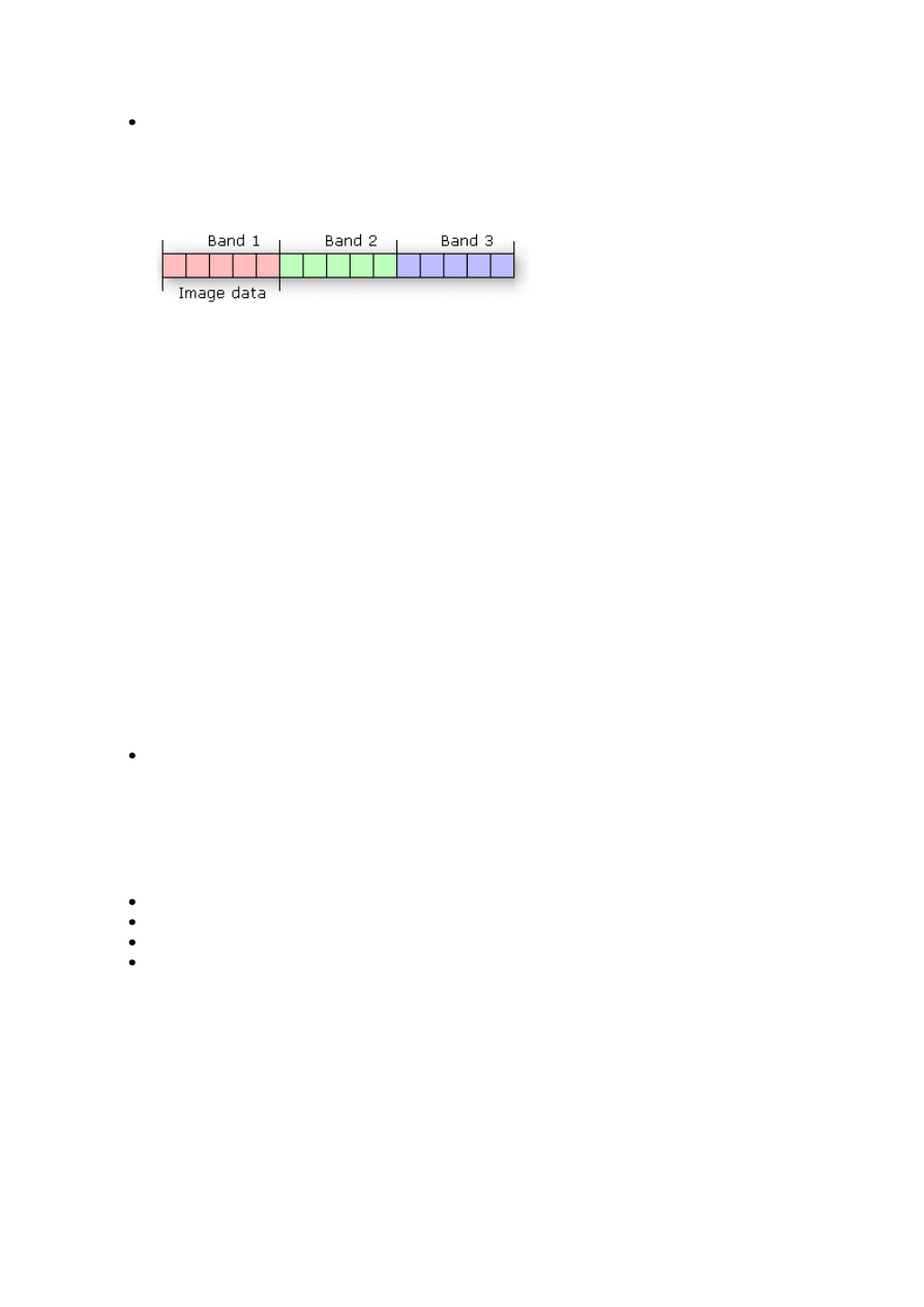
If there are no extra trailing bits at the end of a band, bandrowbytes equals the number of bytes
used to store the image data.
bandrowbytes = image data
For example, given a 6-by-6 image with three bands and 8 bits (1 byte) per pixel, the image
data will require 6 bytes per band per row.
bytes per band per row = ncols x nbits
= 6 x 8
= 48 bits or 6 bytes
By default, bandrowbytes is set to 6 bytes, as shown by the following equation:
bandrowbytes = (ncols x nbits) / 8
= (6 x 8) / 8
= 48 / 8
bandrowbytes = 6 bytes
Because the number of bytes per band per row equals bandrowbytes, the default value is the
appropriate setting. Thus, bandrowbytes does not need to be explicitly specified.
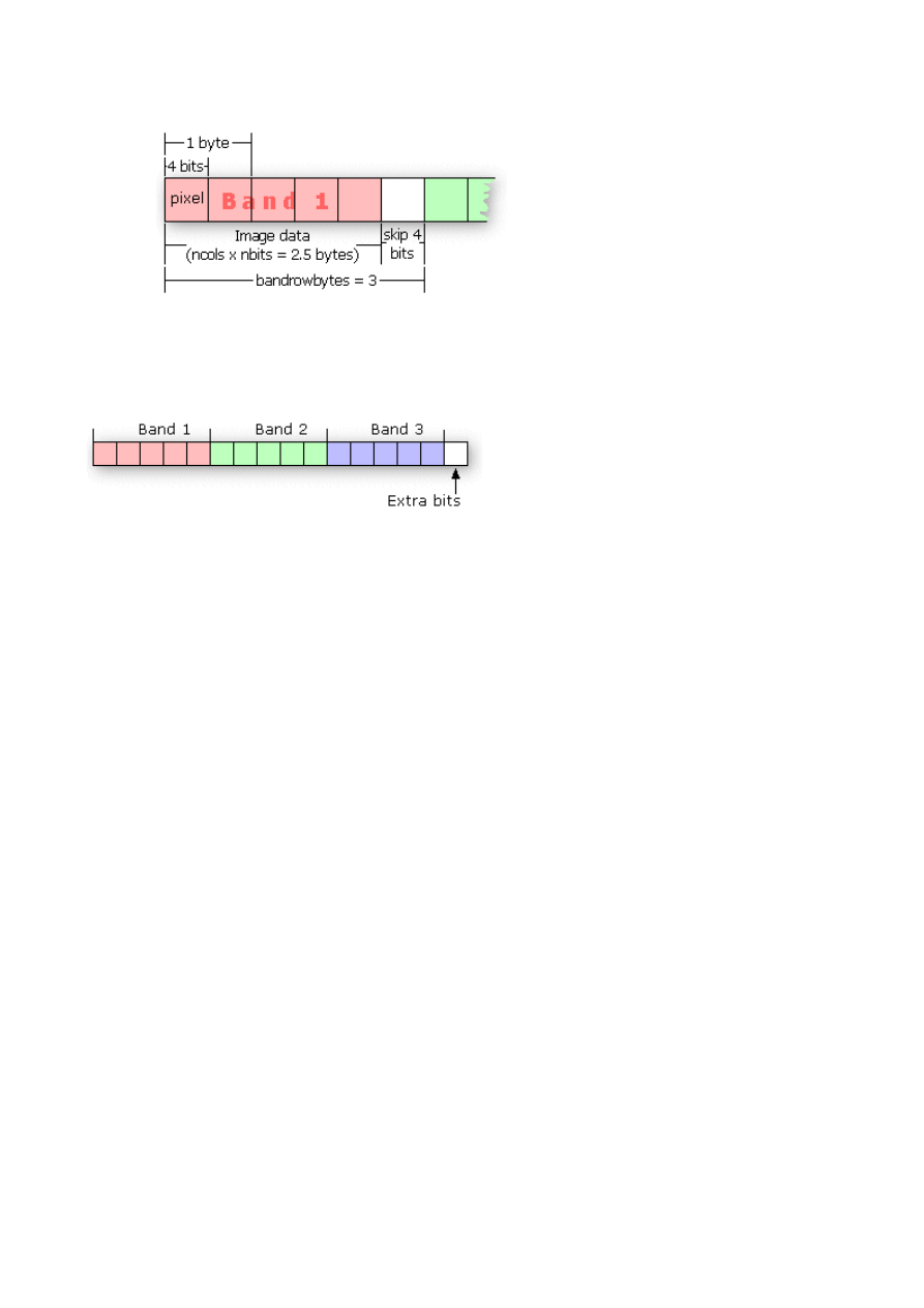
If there are trailing bits at the end of a band in a row, then bandrowbytes does not equal the
number of bytes of data per band per row.
Suppose you have a three-band image of 5 rows and 5 columns with 4 bits per pixel. By
default, bandrowbytes is set to the smallest integer number of bytes that will adequately hold
the data. In this case, the default value is 3. This is calculated as follows:
bandrowbytes = (ncols x nbits) / 8
= (5 x 4) / 8
= 20 / 8
= 2.5
= 3 (when rounded up to the nearest integer)
The image data, however, only requires 2.5 bytes, which is calculated by multiplying ncols
by nbits. Thus, the number of bytes that will be skipped is .5 bytes (4 bits), or the difference
between 3 bytes (bandrowbytes) and 2.5 bytes (image data bytes). The figure below shows
one band of data for one row of the image.
totalrowbytes—The total number of bytes of data per row. Use totalrowbytes when there are extra
trailing bits at the end of each row.
For a BIL file, the default value for totalrowbytes is calculated with the following equation:
totalrowbytes = nbands x bandrowbytes
The default value assumes that there are no extra trailing bits at the end of each row. If there are, set
totalrowbytes accordingly. For example, given a three-band image with bandrowbytes equal to 3,
totalrowbytes will equal 9 by default. If there is an extra trailing byte of data at the end of the row, set
totalrowbytes to 10.
For a BIP file, the default value is calculated with a different equation:
totalrowbytes = (ncols x nbands x nbits) / 8
Totalrowbytes is rounded up to the nearest integer number of bytes that can adequately store the pixel
data for the row. For example, given a 5 (rows) by 5 (columns) BIP image with 3 bands and 4 bits per
pixel, the default value for totalrowbytes is:
totalrowbytes = (ncols x nbands x nbits) / 8
= (5 x 3 x 4) / 8
= 60 / 8
= 7.5
= 8 (when rounded up to the nearest integer)
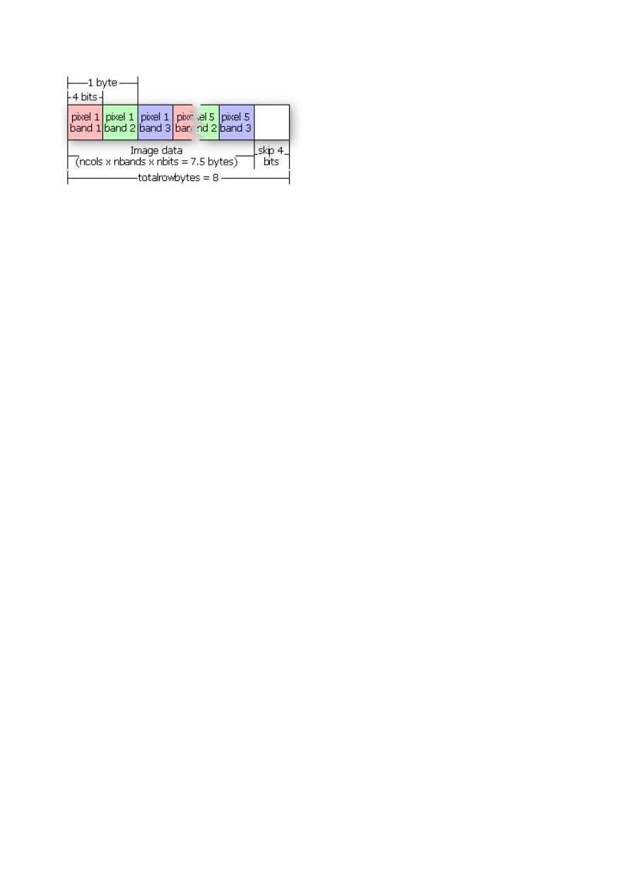
This figure illustrates the default setting of totalrowbytes for a BIP image.
If the default value for totalrowbytes does not accurately represent the layout of the data, totalrowbytes
must be set to the appropriate number of bytes in each row.
bandgapbytes—The number of bytes between bands in a BSQ format image. The default is 0.
The following is a typical header file that might be generated for a band interleaved by line satellite
image where the image data is preceded by a 128-byte header.
Sample BIL header file
Lines that don't begin with a keyword are treated as comments.
nrows 1024 Comments can be placed here as well.
ncols 1024
nbands 3
nbits 8
layout bil
skipbytes 128
The following table gives a summary of the keywords that can be used in the .hdr file:
Keyword
Acceptable Value Default
nrows
any integer > 0
none
ncols
any integer > 0
none
nbands
any integer > 0
1
nbits
1, 4, 8, 16, 32
8
byteorder
I = Intel;
M = Motorola
same as host machine
layout
bil, bip, bsq
bil
skipbytes
any integer ≥ 0 0
ulxmap
any real number 0
ulymap
any real number nrows - 1
xdim
any real number 1
ydim
any real number 1
bandrowbytes any integer > 0
smallest integer ≥ (ncols x nbits) / 8
totalrowbytes any integer > 0
for bil: nbands x bandrowbytes;
for bip: smallest integer ≥ (ncols x nbands x nbits) / 8
bandgapbytes any integer ≥ 0
0

The color file
The color file (.clr) is an optional file that describes the image color map for single-band pseudo color
images. If this file doesn’t exist, the image displays as a grayscale image.
The color file records the colors to be associated with pixel values in the image. Colors are defined
using the RGB color model that describes colors in the amount of red, green, and blue they contain.
The file consists of a set of entries, each on a separate line, that describes the color corresponding to a
pixel value in the image.
Each entry has the format:
<value> <red> <green> <blue>
in which <value> is a given pixel value and <red>, <green>, and <blue> are the color components for
the pixel. Sort all entries in ascending order by pixel value. If the first nonblank character on the line is
not a number, the line is considered a comment and is ignored. Any nonblank characters in a line
beyond the fourth parameter (blue) are ignored and may be used as comments as well.
The red, green, and blue components are described using a scale with values ranging from 0 to 255. As
the color value increases, so does the intensity of the particular color component. The default color for
a pixel value with no entry is black. A sample color file for a raster soils map with pixel values of 11,
16, 18, 19, 21, 98, and 99 is shown below:
Color file for Soils map
Entries are sorted in ascending order by pixel value.
11 255 0 0 (red)
16 255 165 0 (orange)
18 255 255 0 (yellow)
19 0 255 0 (green)
21 0 0 255 (blue)
98 0 255 255 (cyan)
99 160 32 240 (purple)
Color files are only used with single-band images. Any single-band image with a color file will be
interpreted as a pseudo color image. Color files that accompany multiband images are ignored.
The statistics file
The statistics file (.stx) is an optional file that describes image statistics for each spectral band in a
grayscale or multiband image. The file consists of a series of entries, one for each band, that records
the minimum pixel value, the maximum pixel value, the mean, the standard deviation, and two linear
contrast stretch parameters.
Each entry has the format (all values appear on the same line in the file for each band):
<band> <minimum> <maximum> {mean} {std_deviation}
{linear_stretch_min} {linear_stretch_max}
in which <band> is the band number, <minimum> is the minimum pixel value in the band,
<maximum> is the maximum pixel value in the band, {mean} is the mean pixel value, {std_deviation}
is the standard deviation, {linear_stretch_min} is the minimum pixel value for a linear contrast stretch,
and {linear_stretch_max} is the maximum pixel value for a linear contrast stretch.
The values for each parameter are entered on one line. Any entry in which the first nonblank character
is not a number is treated as a comment and ignored. The band number and the minimum and
maximum pixel values are required parameters; the mean, the standard deviation, linear stretch
minimum value, and linear stretch maximum value are optional parameters. Use a "#" to skip the
optional parameters.
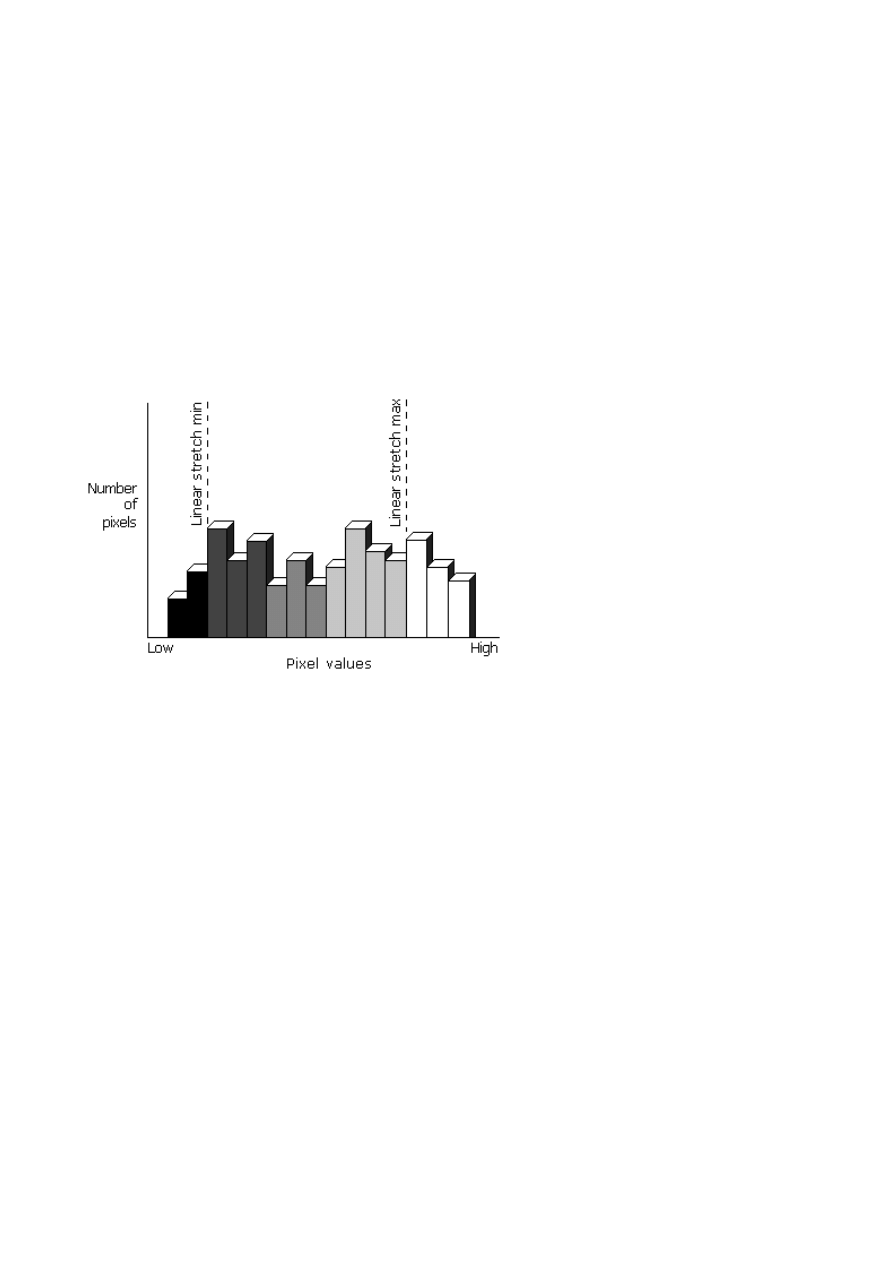
Band numbers can range from 1 to nbands. The linear_stretch_min and linear_stretch_max parameters
are used to expand the contrast of the displayed image. Pixel values less than linear_stretch_min are
displayed in black, and pixel values greater than linear_stretch_max are displayed in white. The pixel
values that fall between the minimum and maximum linear stretch parameters are displayed using
shades of gray, with lower pixel values being displayed in darker shades of gray.
The pixel values that fall between the linear stretch parameters are displayed using the maximum
number of gray shades available on the display device.
If linear_stretch_min and linear_stretch_max are not specified, they default to the mean minus two
standard deviations for linear_stretch_min and the mean plus two standard deviations for
linear_stretch_max. If the standard deviation is not given, the minimum and maximum pixel values are
used as the contrast stretching parameters.
For multiband images, each band is stretched before the composite image displays. The presence of a
color file (.clr) will override the linear contrast stretching of a single-band grayscale image and,
instead, display the image as a pseudo color image.
The following is a sample statistics file for a four-band satellite image with 8 bits per pixel per band:
Image statistics file
1 2 118 67 10
Band 2 has linear contrast stretch parameters:
2 23 251 112 23 80 90
3 68 91 73 4
Band 4 does not contain values for mean and standard deviation:
4 126 198 # # 135 167

////////////////////////
Source:
http://webhelp.esri.com/arcgisdesktop/9.2/index.cfm?TopicName=Supported_raster_dataset_file_formats
Show Navigation |
You are here:
Data support in ArcGIS > Raster data > Understanding raster data
Supported raster dataset file formats
Release 9.2
Last modified September 22, 2008
Print all topics in :
Related Topics
Technical specifications for raster dataset formats
Data formats supported in ArcGIS
is the native data model in ArcGIS for storing geographic information, including
raster datasets and raster catalogs; however, there are many file formats you can work with that are
maintained outside a geodatabase. The following table gives a description of the supported raster
formats and their extensions and identifies if they are read-only or if they can also be written by
ArcGIS.
Learn how to add file extensions to ArcCatalog or search all files
Learn more about the technical specifications for raster formats
Format
Description
Extension(s)
Read/Write
ARC Digitized
Raster Graphics
(ADRG)
Distributed on CD-ROM by the
National Geospatial-Intelligence
Agency
geographically referenced using the
equal arc-second raster chart/map
(ARC) system in which the globe is
divided into 18 latitudinal bands or
zones. The data consists of raster
images and other graphics generated
by scanning source documents.
Multiple files
Data file—extension *.img
or *.ovr
Legend file—extension
*.lgg
Read-only
ArcSDE raster
Raster data stored within an ArcSDE
database.
Stored in SDE database.
Read and
write
ASCII Grid
The ArcInfo ASCII Grid format is an
ArcInfo Grid exchange file.
Single file—extension
*.asc
Read-only
Band interleaved by
line (ESRI BIL),
band interleaved by
pixel (ESRI BIP),
band sequential
This format provides a method for
reading in and displaying
decompressed, BIL, BIP, and BSQ
image data. By creating an ASCII
description file that describes the
Multiple files:
Data file—extension *.bil,
*.bip, or *.bsq
Header file—extension
*.hdr
Read-only

(ESRI BSQ)
layout of the image data, black-and-
white, grayscale, pseudo color, and
multiband image data can be displayed
without translation into a proprietary
format.
Colormap file—extension
*.clr
Statistics file—extension
*.stx
Bitmap (BMP),
device-independent
bitmap (DIB) format,
or Microsoft
Windows bitmap
BMP files are Windows bitmap
images. They are usually used to store
pictures or clip art that can be moved
between different applications on
Windows platforms.
Single file—extension
*.bmp
World file—extension
*.bpw
Read and
write
BSB
This is a compressed raster format
used in the distribution of raster
nautical charts by
and
Multiple files—extension
*.bsb, *.cap, and *.kap
Read-only
Compressed ARC
Digitized Raster
Graphics (CADRG)
Distributed on CD-ROM by NGA.
CADRG is geographically referenced
using the ARC system in which the
globe is divided into 18 latitudinal
bands, or zones. The data consists of
raster images and other graphics
generated by scanning source
documents. CADRG achieves a
nominal compression ratio of 55:1.
Single file—no standard
file extension.
Choose to search all files or
add your file extensions to
ArcCatalog.
Read-only
Controlled Image
Base (CIB)
Panchromatic (grayscale) images that
have been georeferenced and corrected
for distortion due to topographic relief
distributed by NGA. Thus, they are
similar to digital orthophoto quads and
have similar applications, such as
serving as a base or backdrop for other
data or as a simple map.
Single file—no standard
file extension.
Choose to search all files or
add your file extensions to
ArcCatalog.
Read-only
Digital Geographic
Information
Exchange Standard
(DIGEST)
Arc Standard Raster
Product (ASRP),
UTM/UPS Standard
Raster Product
(USRP)
DIGEST datasets are digital replicas
of graphic products designed for
seamless worldwide coverage. ASRP
data is transformed into the ARC
system and divides the earth's surface
into latitudinal zones. USRP data is
referenced to UTM or UPS coordinate
systems. Both are based on the WGS
1984 datum.
Multiple files
Main raster image—
extension *.img
General information file—
extension *.gen
Georeference file—
extension *.ger
Source file—extension
*.sou
Quality file—extension
*.qal
Transmission header file—
extension *.thf
Read-only
Digital Terrain
Elevation Data
(DTED) Level 0, 1,
and 2
A simple, regularly spaced grid of
elevation points, base on 1 degree
latitude and longitude extents. Created
by the NGA.
Single file—various file
extensions *.dt0, *.dt1,
*.dt2
All possible file extensions
Read-only

are available by default
(*.dt0, *.dt1, *.dt2).
ECW
Enhanced Compressed Wavelet
(ECW) format is able compress
extremely large images at high
compression ratios, while still
providing fast data access and high
visual quality.
Single file—extension
*.ecw
Read-only
ER Mapper
A proprietary raster format from ER
Mapper. Produced using the ER
Mapper image processing software.
Multiple files
Header file—extension
*.ers
Data file—usually same as
header file without the
*.ers extension but could
be any and is defined in the
header file.
Read-only
ERDAS 7.5 GIS
Single-band thematic images produced
by ERDAS 7.5 image processing
software.
Multiple files
Data file—extension *.gis
Color map file—extension
*.trl
Read-only
ERDAS 7.5 LAN
Single- or multiband continuous
images produced by the ERDAS 7.5
image processing software.
Multiple files
Data file—extension *.lan
Color map file—extension
*.trl
Read-only
ERDAS IMAGINE
Produced using IMAGINE image
processing software created by
ERDAS. IMAGINE files can store
both continuous and discrete, single-
band and multiband data.
Single file—extension
*.img
If image is bigger than 2
GB—extension *.ige
World file—extension
*.igw
Read and
write
ERDAS RAW
Provides a method for reading and
displaying files that are not otherwise
supported by another format but are
formatted in such a way that the
arrangement of the data may be
described by a relatively small number
of parameters. By creating an ASCII
file that describes the layout of the
raster data, it can be displayed without
translation in a proprietary format. The
format is defined in the ERDAS
IMAGINE software.
Single file—extension
*.raw
Read-only
A proprietary ESRI format that
supports 32-bit integer and 32-bit
floating-point raster grids. Grids are
useful for representing geographic
phenomena that vary continuously
over space and for performing spatial
Directory colormap file—
extension *.clr
Read and
write

modeling and analysis of flows,
trends, and surfaces such as
hydrology.
Used to reference multiple ESRI Grids
as a multiband raster dataset. A stack
is stored in a directory structure
similar to a grid or coverage.
Directory
Read and
write
ESRI Grid stack file
Used to reference multiple ESRI Grids
as a multiband raster dataset. A stack
file is a simple text file that stores the
path and name of each ESRI Grid
contained within it on a separate line.
Single file—possible file
extension *.stk
Read and
write
Graphic Interchange
Format (GIF)
A proprietary image format that is
highly compressed and requires an
LZW license from Unisys. Allows
high-quality, high-resolution graphics
to be displayed on a variety of
graphics hardware and is intended as
an exchange and display mechanism
for graphic images.
Single file—extension *.gif
World file—extension
*.gfw
Read and
write
Hierarchical Data
Format (HDF) 4
A self-defining file format used for
storing arrays of multidimensional
data.
Single file—extension
*.hdf
Read-only
Idrisi Raster Format
(RST)
File format native to
Multiple files
Raw image—extension
*.rst
descriptor—extension *.rdc
color map—extension
*.smp
georeference file—
extension *.ref
Read-only
Intergraph raster
files:
CIT—Binary data;
COT—Grayscale
data
Intergraph's proprietary format for 16-
bit imagery (CIT) and unsigned 8-bit
imagery (COT).
Multiple files
Binary imagery—extension
*.cit
Grayscale imagery—
extension *.cot
Read-only
Joint Photographic
Experts Group
(JPEG) File
Interchange Format
(JFIF)
A standard compression technique for
storing full-color and grayscale
images. Support for JPEG
compression is provided through the
JFIF file format.
Single file—Possible file
extensions are *.jpg,
*.jpeg, *.jpc, and *.jpe.
World file—extension
*.jgw
ArcCatalog only recognizes
the .jpg file extension by
default. To add .jpeg or .jpe
files to ArcMap without
renaming them, add those
file extensions to
ArcCatalog or drag those
files from Windows
Read and
write

Explorer into your map.
JPEG 2000
A compression technique especially
for maintaining the quality of large
imagery. Allows for a high-
compression ratio and fast access to
large amounts of data at any scale.
Single file—extension
*.jp2, *.j2c, or *.j2k
Read and
write
MAP
Single file—extension
*.map
Read-only
Multiresolution
Seamless Image
Database (MrSID)
A compression technique especially
for maintaining the quality of large
images. Allows for a high-
compression ratio and fast access to
large amounts of data at any scale.
Single file—extension *.sid
World file—extension
*.sdw
Read-only
National Imagery
Transmission Format
(NITF)
A collection of standards and
specifications that allow for
interoperability in the dissemination of
imagery and it's metadata among
various computer systems. Developed
by the NGA.
Read-only
PCIDSK
Single file—extension
*.pix
Read-only
Portable Network
Graphics (PNG)
Provides a well-compressed, lossless
compression for raster files. It supports
a large range of bit depths from
monochrome to 64-bit color. Its
features include indexed color images
of up to 256 colors and effective 100
percent lossless images of up to 16 bits
per pixel.
Single file—extension
*.png
Read and
write
Raster Product
Format (RPF)
The underlying format of CADRG,
ADRG and CIB.
Single file—no standard
file extension.
Read-only
Tagged Image File
Format (TIFF)
(GeoTIFF tags are
supported.)
Widespread use in the desktop
publishing world. It serves as an
interface to several scanners and
graphic arts packages. TIFF supports
black-and-white, grayscale, pseudo
color, and true color images, all of
which can be stored in a compressed
or decompressed format.
Single file—possible file
extensions *.tif, *.tiff, and
*.tff
World file—extension
*.tfw
ArcCatalog only recognizes
the .tif file extension by
default. To add .tiff or .tff
files to ArcMap without
renaming them, add those
file extensions to
ArcCatalog or drag those
files from Windows
Explorer into your map.
Read and
write
United States
Geological Survey
(USGS) digital
This format consists of a raster grid of
regularly spaced elevation values
derived from the USGS topographic
Single file—extension
*.dem (need to change .dat
extension to .dem)
Read-only

elevation model
(DEM)
map series. In their native format, they
are written as ANSI-standard ASCII
characters in fixed-block format.
Stores color images in a format
consisting of an ASCII image and a C
library.
Single file—extension
*.xpm
Read-only
Building a customized raster format
Raster format support in ArcGIS is built on an open structure. With this open structure, you can add
your own raster format support to ArcGIS by creating a format driver. ArcGIS 9.2 has adopted the
Geospatial Data Abstract Library (GDAL) and supports adding custom formats through the GDAL
format driver.
For information on implementing a GDAL format driver, see
www.remotesensing.org/gdal/gdal_drivertut.html
To configure the GDAL format driver with ArcGIS, the GDAL format driver should be named with a
prefix "gdal_" and with the extension ".so" or ".dll", such as gdal_fm.dll.
The steps to plug in a GDAL format driver to ArcGIS are:
1. Copy the GDAL format driver to the ArcGIS bin directory (i.e. C:\Programs
Files\ArcGIS\Bin).
2. In the ArcGIS bin folder, back-up RasterFormats.dat, and save it to another location.
3. Open RasterFormats.dat in a text editor.
4. Add a line at the end with the information about the new format.
For example:
<e on="y" nm="ABC" ex="*.abc" et="ABC" at="0x27" />
where
in nm="ABC", ABC is the format name
in ex="*.abc", .abc is the format extension
in et="ABC", ABC is the format string
in at="0x27", 0x27 means read; can also be 0x0f which means read/write
5. Close all ArcGIS applications and restart them for the format changes to take effect.
ArcGIS still supports the legacy method of adding a custom DLL. For more information on this
method, see the
. Search for "Building a Customized Raster Format
DLL" in the Search dialog on this site.
Wyszukiwarka
Podobne podstrony:
Aidfile Format Drive Recovery Info
10 Formatowanie Dysku Twardego i Dzielenie Go Na Partycje(bitnova info)
10 Formatowanie Dysku Twardego i Dzielenie Go Na Partycje bitnova info
Prezentacja formatka
scripps short
Formaty plików dźwiękowych
pn2refresher short
L 5590 Short Sleeved Dress With Zipper Closure
Info topgrafia 2012
Info
info tech geodeta (1)(1)
Przekroje Format A2
MaturaSolutionsAdvanced Unit 10 short test 1 and 2
CLK EC08 Visit Info
Info Page 1
info 2
h 1 formatka 2012 budowa hv
więcej podobnych podstron