1
INTRODUCTION
GENERAL
This section describes the parts and operation of the Vis-
ta
MASTS. Repair procedures for the Vista
MASTS
are described in the section, VISTA
MASTS, RE-
PAIR, 4000 SRM 223. The lift cylinders and the lower-
ing control valves are described in the section, LIFT
CYLINDERS, 4000 SRM 135. The description and re-
pairs for the tilt cylinders are described in the section
THE TILT CYLINDERS, 2100 SRM 103.
An MAST is used to lift a load vertically. The MAST
has two movements controlled by hydraulic cylinders:
forward and backward tilt and the telescopic move-
ments of the vertical frames. The outer weldment can ro-
tate on a pivot on the drive axle of the lift truck. The op-
eration of the tilt cylinders causes the MAST to tilt for-
ward and backward. The tilt cylinders are fastened be-
tween the frame of the lift truck and the outer weldment
of the lift truck. Hydraulic lift cylinders are installed
vertically on the MASTS. The lift cylinders raise and
lower the vertical frames and the carriage.
There are four types of Vista
MASTS available:
•
two–stage
•
f
ree–lift
•
three–stage
•
four–stage (E/S2.00–3.00XL [E/S40–60XL]
only)
Each type of MAST is described separately in this sec-
tion.
MAST WELDMENTS
The main vertical frames of a MAST are called weld-
ments. Channels, load rollers, and cross members are
parts of the weldments. All of the MASTS have tele-
scopic weldments. Each side of a weldment is a channel.
The channels are the primary support members of the
MAST and the tracks for the load rollers. When the
MAST and the carriage lift a load, large forces are put on
the MAST assembly. The load rollers reduce the friction
between the channels when the weldments are moved
vertically.
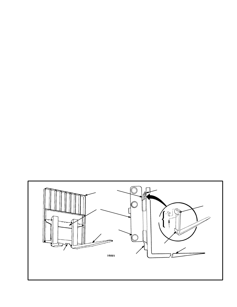
CARRIAGE
(See FIGURE 1. and FIGURE 2. )
Each MAST has a carriage. The carriage is a separate
section that moves within the vertical channels of the in-
ner weldment. Load rollers, attached to the carriage,
travel in the channels of the inner weldment. Forks or
other types of load handling equipment are attached to
the carriage. A load backrest extension is part of the car-
riage that adds support for a load that has multiple
pieces. See FIGURE 1.
1545
FIGURE 1. CARRIAGE AND FORKS
1. LOAD BACKREST EXTENSION
2. FORK REMOVAL NOTCH
3. LOAD ROLLER
4. CARRIAGE
5. FORK
6. HOOK
7. LOCK PIN ASSEMBLY
1
2
3
4
5
6
7
6
6
6
5
7
2
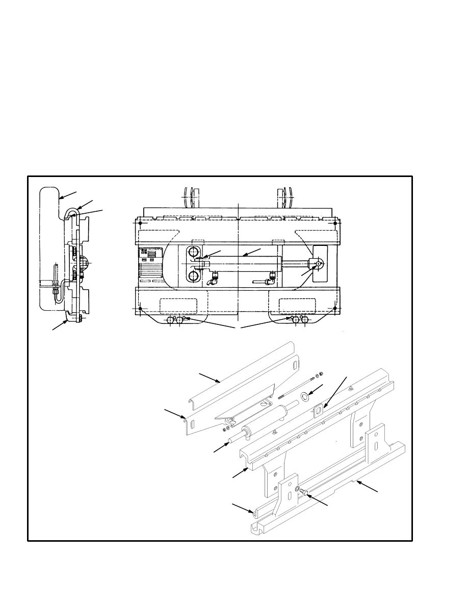
A side–shift carriage is often used on this series of
MASTS. See FIGURE 2. A side–shift carriage permits
the operator to hydraulically change the horizontal posi-
tion of the load handling device on the carriage. This
function makes it easier for the operator to align the
forks with a load or align the load with a stack.
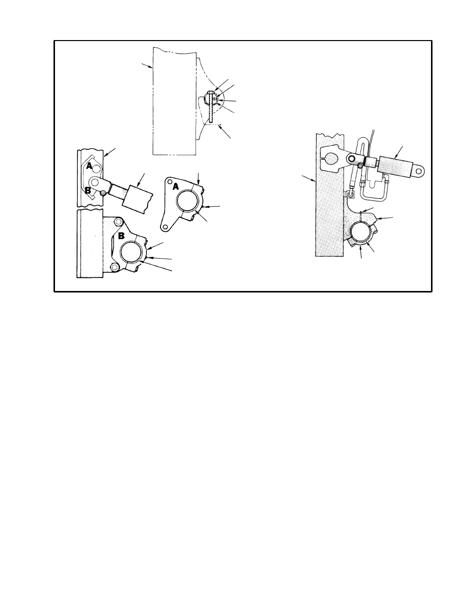
MAST MOUNTS (See FIGURE 3.)
Each MAST can tilt forward and backward. Tilt cylin-
ders are fastened between the frame of the lift truck and
the outer channels of the MAST to change the tilt of the
MAST and forks. See FIGURE 3. The tilt cylinders are
double–action hydraulic cylinders. The operation of the
main control valve to control the lift cylinders is de-
scribed in the hydraulic section for each series of lift
trucks. A pivot is welded to the bottom of each outer
channel and fastens the MAST to the lift truck, but per-
mits the MAST to tilt. The pivot assembly rotates on the
drive axle housing. The drive wheels are different sizes
for the different series of lift trucks that use this design
of MAST. This difference in drive wheels requires that
each series of lift trucks has its own design of pivot as-
sembly. The pivot assemblies for the different series of
lift trucks are similar in design, but are not the same.
10907
1. CARRIAGE
2. CARRIAGE APRON
3. ANCHOR PIN
4. CARRIAGE HOOK
FIGURE 2. SIDE–SHIFT CARRIAGES
1
2
3
4
5
6
7
3
LATE MODELS
EARLY MODELS
6
5. BEARING
6. SIDE–SHIFT CYLINDER
7. ADJUSTMENT HOLES
8. TOP APRON
9. BOTTOM APRON
10. TOP BEARING
11. BOTTOM BEARING
12. SHIM
13. ASSEMBLY CAPSCREW
14. CYLINDER MOUNTING BRACK-
ET
15. LIFTING EYE
8
9
10
11
12
13
14
15
3
11369
E/S2.00–3.00XL
(E/S40–60XL)
H2.00–3.00XL
(H40–60XL)
A = H1.25–1.75XL
(H25–35XL)
B = E/S1.25–1.75XL
(E/S25–35XL)
10672
FIGURE 3. MAST MOUNTS
1. OUTER WELDMENT
2. MAST PIVOT
3. MAST PIVOT CAP
4. BUSHING
5. TILT CYLINDER
6. GREASE FITTING
7. CAPSCREW
8. PIN
9. MOUNT BRACKET, DRIVE AXLE
11369
1
2
3
5
6
7
8
9
1
1
3
3
4
4
4
4
5
6
6
6
VISTA
TWO–STAGE MAST
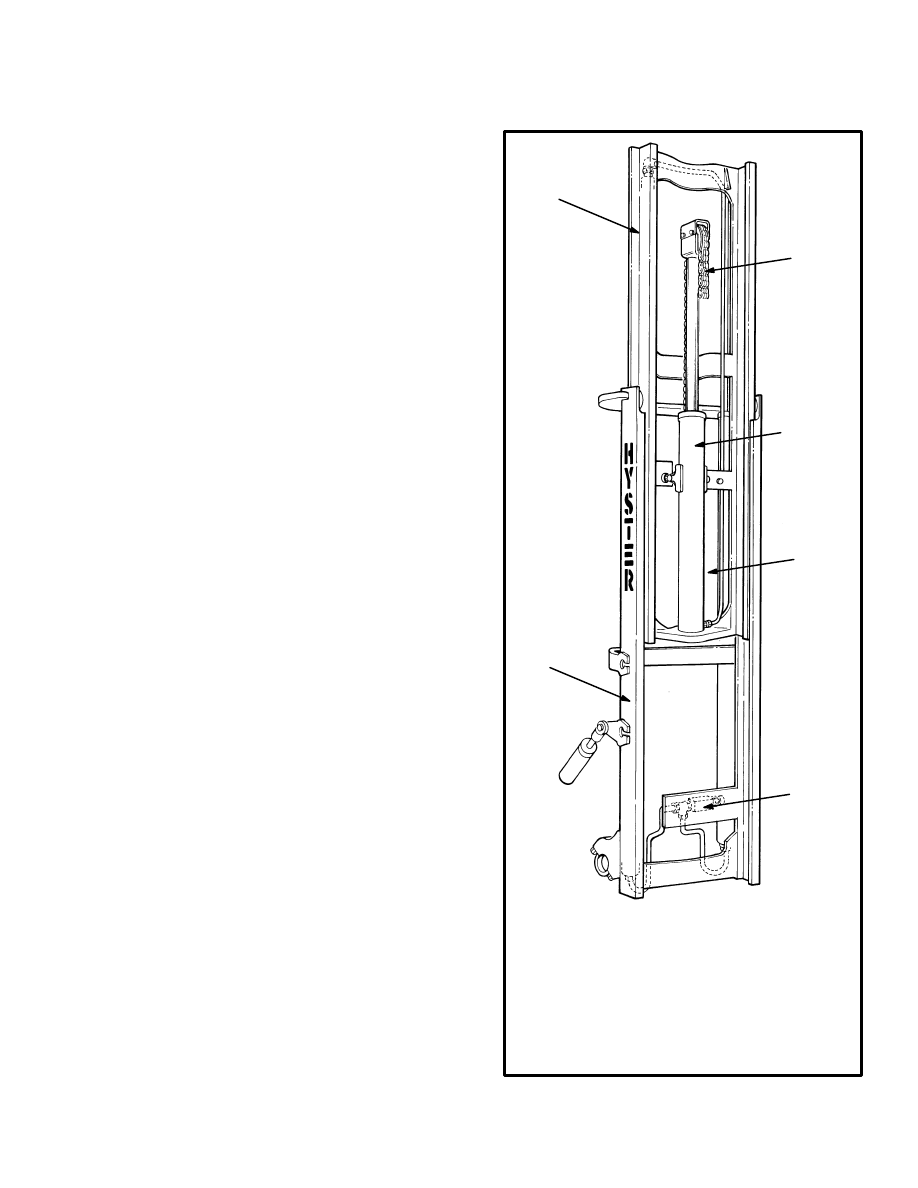
DESCRIPTION AND OPERATION
The Vista
two–stage MAST has two weldments as
shown in FIGURE 4. The base of the inner weldment
has one load roller on each side. The load rollers travel
along the channels within the outer weldment. The top
of the outer weldment also has one load roller on each
side. These load rollers travel along the outside channels
of the inner weldment. The angle of the load rollers per-
mits them to control the forces from the front, back and
sides of the MAST. The strip bearings are installed at the
top of each outer channel. The strip bearings keep the
correct clearance between the outer weldment and the
inner weldment.
The Vista
two–stage MAST assembly has two single–
stage lift cylinders. The lift cylinders are installed at the
back of the outer weldment. The base of each lift cylin-
der is held by a steel mount plate at the bottom of the
outer weldment. The hydraulic fitting for each lift cylin-
der goes through a hole in the mount plate. The top of
each lift cylinder (cylinder rods) fits into guides at the
top of the inner weldment. Operation of the lift cylinders
extends and retracts the inner weldment.
Two lift chains control the movement of the carriage.
The chains fasten to mounts that are welded near the top
of the lift cylinder shells. The chains go up and over the
chain sheaves and then connect to the carriage. The
chain sheaves are installed near the top of the inner
weldment. When the lift cylinders extend, the lift chains
transfer the force from the lift cylinders to the carriage.
The carriage will rise a small amount before the overall
height of the MAST increases because the inner weld-
ment is shorter than the outer weldment.
When the lift cylinders retract, the weight of the load,
carriage and inner weldment pushes the oil from the lift
cylinders. The oil flows from the lift cylinders, through
the lowering control valves, and then to the hydraulic
tank.
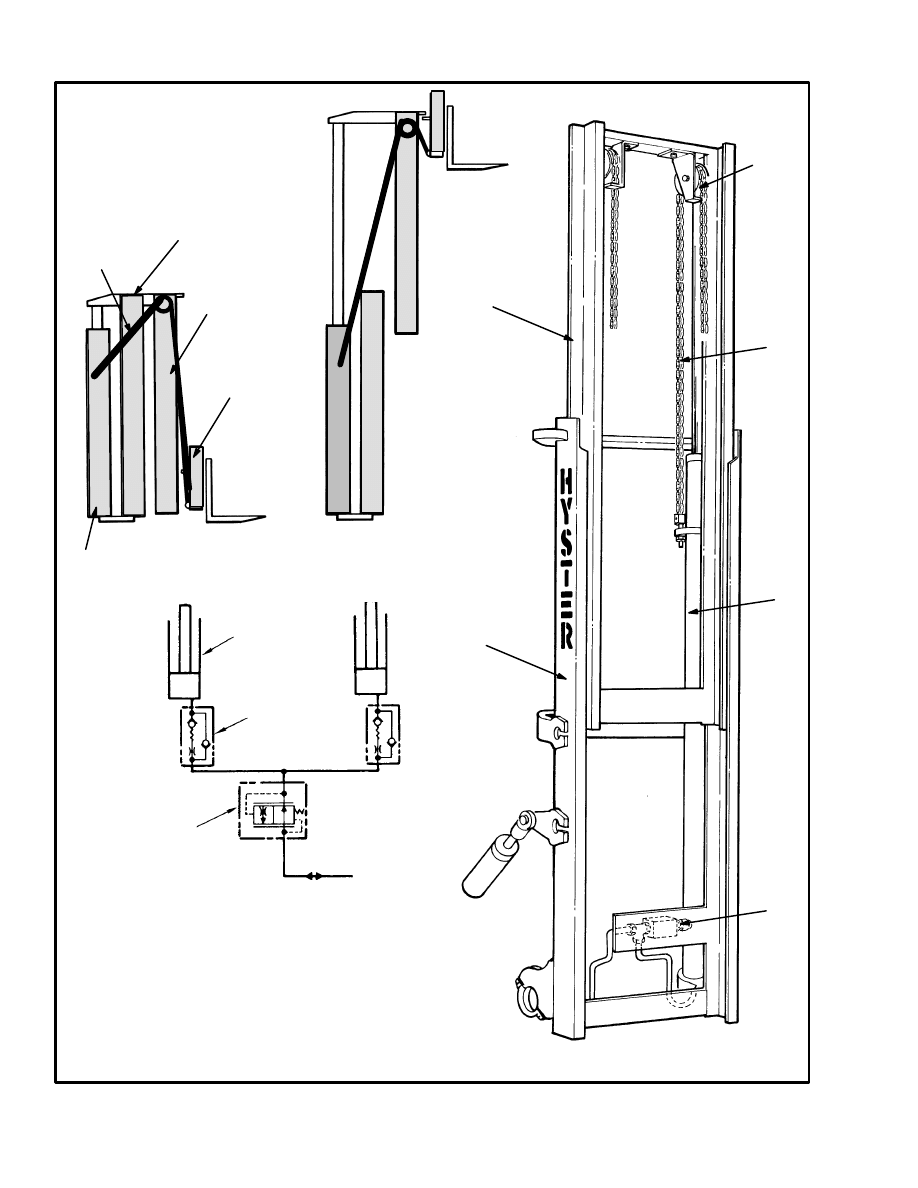
4
10641
10102
PHASE 1 PHASE 2
S/H1.25–1.75XL (S/H25–35XL) MAST IS SHOWN,
OTHER MODELS ARE SIMILAR
FIGURE 4. TWO–STAGE MAST
1. LIFT CYLINDER (2)
2. LIFT CHAIN (2)
3. OUTER WELDMENT
4. CHAIN SHEAVE (2)
5. INNER WELDMENT
6. CARRIAGE
7. FROM MAIN CONTROL VALVE
8. EXTERNAL LOWERING CONTROL VALVE
9. EXTERNAL LOWERING CONTROL VALVE (2)
1
2
3
4
5
6
7
8
9
1
2
3
5
1
8
5
VISTA
FREE–LIFT MAST
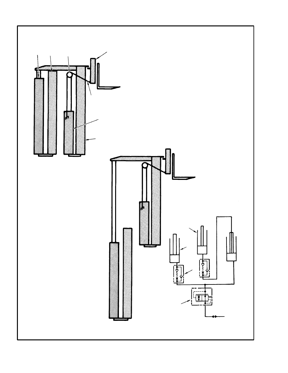
DESCRIPTION (See FIGURE 5.)
The Vista
free–lift MAST has an inner weldment, an
outer weldment and three single–stage lift cylinders. It
is called a free–lift MAST because the carriage can
travel to the top of the inner weldment without increas-
ing MAST height. The Vista
free–lift MAST has load
roller and strip bearing arrangements similar to the Vis-
ta
two–stage MAST.
Two main lift cylinders are installed at the back of the
outer weldment. The base of each lift cylinder is held by
a steel mount plate at the bottom of the outer weldment.
The hydraulic fitting for each lift cylinder goes through
a hole in the mount plate. The top of each lift cylinder
(cylinder rod) fits into a guide at the top of the inner
weldment. The free–lift cylinder is installed in the inner
weldment. The main lift cylinder on the right side of the
MAST and the free–lift cylinder each have an internal
lowering control valve. A single external lowering con-
trol valve is connected by tubing to all the lift cylinders.
A chain sheave is installed on the cylinder rod of the
free–lift cylinder. The lift chain is connected to the shell
of the lift cylinder. The chain then goes over the sheave
and connects to the carriage.
OPERATION (See FIGURE 6.)
The three lift cylinders are connected by hoses and tub-
ing as shown in When the MAST is extended, oil flows
from the main control valve to the base of the main lift
cylinders. The oil then flows through the left–hand cyl-
inder rod and through tubing to the base of the free–lift
cylinder. The free–lift cylinder raises only the carriage.
When the free–lift cylinder is fully extended, the two
main lift cylinders extend the inner weldment. The free–
lift cylinder extends first because it has less weight to
lift. When the load is lowered, the main lift cylinders
lower first because they have a greater load. The oil
flows from the main lift cylinders, through the lowering
control valves to the hydraulic tank. Oil from the free–
lift cylinder flows from the cylinder and through tubing
to the cylinder rod on the left side of the MAST. The oil
then flows from the left–hand lift cylinder to the hydrau-
lic tank.
S2.00–3.00XL (S40–60XL) UPRIGHT
IS SHOWN, OTHER MODELS ARE SIMILAR
10640
FIGURE 5. FREE–LIFT MAST
1. OUTER WELDMENT
2. INNER WELDMENT
3. MAIN LIFT CYLINDERS
4. FREE–LIFT CYLINDER
5. EXTERNAL LOWERING CONTROL VALVE
6. LIFT CHAIN
1
2
3
4
5
6
6
10638
PHASE 2
PHASE 1
FIGURE 6. FREE–LIFT OPERATION
1. MAIN LIFT CYLINDER (2)
2. OUTER WELDMENT
3. FREE–LIFT CYLINDER
4. INNER WELDMENT
5. CHAIN SHEAVE
6. LIFT CHAIN
7. CARRIAGE
8. FROM MAIN CONTROL VALVE
9. EXTERNAL LOWERING CONTROL VALVE
10. INTERNAL LOWERING CONTROL VALVE
1
2
3
4
5
6
7
8
9
10
1
3
7
VISTA
THREE–STAGE MAST
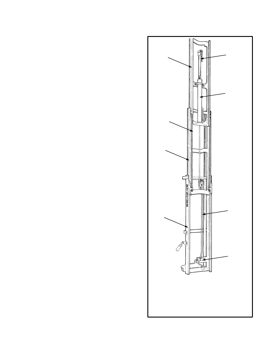
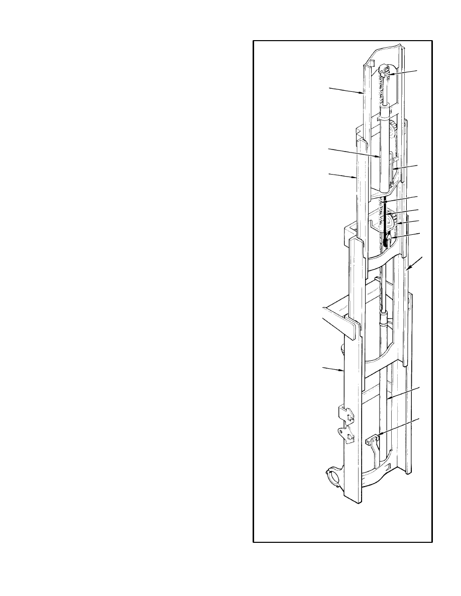
DESCRIPTION (See FIGURE 7.)
Outer, intermediate, and inner weldments are used on
the Vista
three–stage MAST. Two single–stage main
lift cylinders and a free–lift cylinder are used to raise the
carriage and extend the MAST. The weldments are tele-
scopic and have the load roller and strip bearing ar-
rangements similar to the two–stage MAST. The two
main lift cylinders are installed at the back of the outer
weldment. The base of each lift cylinder is held on a
steel mount plate at the bottom of the outer weldment.
The hydraulic fittings for the lift cylinders go through
holes in the mount plate. The top of each main lift cylin-
der (cylinder rod) fits into a guide at the top of the inter-
mediate weldment. The free–lift cylinder fastens to the
inner weldment. The main lift cylinder on the right side
of the MAST and the free–lift cylinder have an internal
lowering control valve. A single external lowering con-
trol valve is connected by tubing to all the lift cylinders.
The two main lift chains fasten at one end near the top of
the outer weldment. The lift chains then go over sheaves
at the top of the intermediate weldment and fasten at the
bottom of the inner weldment. The free–lift chain is con-
nected to the shell of the free–lift cylinder. The chain
then goes over the sheave and connects to the carriage.
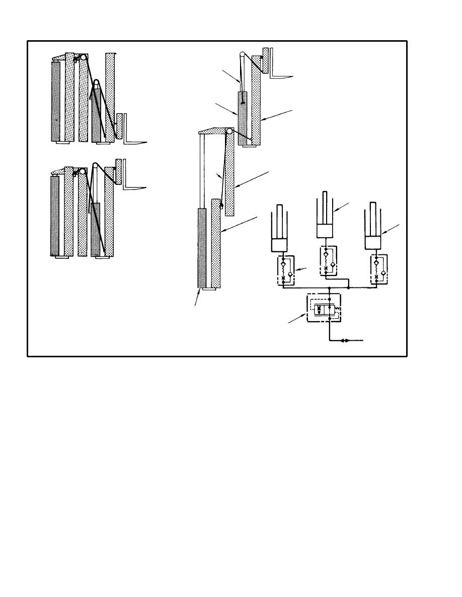
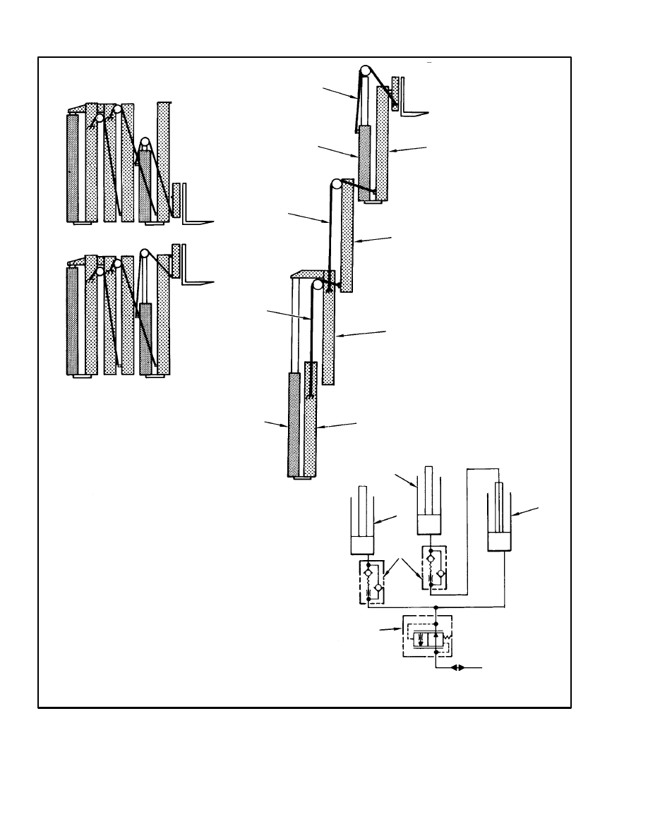
OPERATION (See FIGURE 8.)
The three hydraulic cylinders are connected by hoses
and tubing as shown in FIGURE 8. To extend the
MAST, oil from the main control valve flows to all cyl-
inders at the same time. The free–lift cylinder extends
first because it lifts the least amount of weight. The free–
lift cylinder raises the carriage to the top of the inner
weldment. After the free–lift cylinder reaches the end of
its stroke, the main lift cylinders begin to extend. As the
main lift cylinders extend, the intermediate and inner
weldments extend because of the lift chains.
During lowering, the main lift cylinders lower first be-
cause they have a greater load. After the main lift cylin-
ders have retracted, the free–lift cylinder lowers. All oil
from the lift cylinders flows through the lowering con-
trol valves to the hydraulic tank.
11372
FIGURE 7. THREE–STAGE MAST
1. OUTER WELDMENT
2. INTERMEDIATE WELDMENT
3. INNER WELDMENT
4. FREE–LIFT CYLINDER
5. MAIN LIFT CYLINDER
6. EXTERNAL LOWERING CONTROL VALVE
7. MAIN LIFT CHAIN (2)
8. FREE–LIFT CHAIN
1
2
3
4
5
6
7
8
8
10101
PHASE 1
PHASE 2
FIGURE 8. OPERATION OF THE THREE–STAGE MAST
1. MAIN LIFT CYLINDER (2)
2. MAIN LIFT CHAIN (2)
3. FREE–LIFT CYLINDER
4. FREE–LIFT CHAIN
5. INNER WELDMENT
6. INTERMEDIATE WELDMENT
7. OUTER WELDMENT
8. FROM MAIN CONTROL VALVE
9. EXTERNAL LOWERING CONTROL VALVE
10. INTERNAL LOWERING CONTROL VALVE (3)
1
2
3
4
5
6
7
8
9
10
1
3
VISTA
FOUR–STAGE MAST
DESCRIPTION (See FIGURE 9.)
The Vista
four–stage MAST is a telescoping assembly
that has four weldments as shown in FIGURE 9. The in-
ner weldment moves up and down within the third weld-
ment. The third weldment moves within the second, and
so on. The weldments move on load rollers and strip
bearings. The carriage moves on load rollers. A free–lift
cylinder and chain move the carriage in the inner weld-
ment. The outer weldment has two lift cylinders. The
cylinder rods lift and lower the second weldment. When
the second weldment moves, chains and sheaves move
the third and the inner weldments. Two chains control
the third weldment. These chains are fastened to the
outer and third weldments and travel over sheaves on
the second weldment. Two chains fastened to the second
and inner weldments travel over sheaves on the third
weldment. These chains control the inner weldment.
Oil flows to the free–lift cylinder through the rod of the
left main cylinder. A hose connects the rod to the free–
lift cylinder. Lowering control valves are installed in the
ports of the free–lift cylinder and the right main cylin-
der. Each of these cylinders has an internal valve that re-
turns oil from above the piston. A return line connects
the top of the left cylinder to the top of the right cylinder.
There is an external lowering control valve on the outer
9
weldment. This valve is connected to both main cylin-
ders and to the main control valve.
OPERATION (See FIGURE 10.)
Oil flows from the main control valve to all cylinders at
the same time. The free–lift cylinder operates first be-
cause it has the lightest load and the larger area. This cyl-
inder lifts the carriage to the top of the inner weldment.
The carriage only travels in the inner weldment when
the MAST is fully lowered. When the free–lift cylinder
is fully extended, the pressure increases to extend the
rods of the main cylinders. As the second weldment
moves, it causes the chains to lift the third and the inner
weldments. The three weldments move at the same
time.
During lowering, the rods of the main cylinders retract
first because they have the greater load. When the weld-
ments are fully retracted, reduced pressure allows the
free–lift cylinder to lower the carriage. Oil returns from
the cylinders through the lowering control valves. Low-
ering speed is normally controlled by the external valve.
It regulates all return flow by sensing pressure. When
actuated, the valves in the cylinders provide a fixed
amount of restriction.
12288
FIGURE 9. FOUR–STAGE MAST
1. INNER WELDMENT
2. FREE–LIFT CYLINDER
3. THIRD WELDMENT
4. SECOND WELDMENT
5. OUTER WELDMENT
6. FREE–LIFT CHAIN
7. TUBE
8. LIFT CHAIN (2)
9. HOSE
10. LIFT CHAIN (2)
11. HOSE SHEAVE
12. MAIN LIFT CYLINDER
13. LOWERING CONTROL VALVE (EXTERNAL)
1
2
3
4
5
6
7
8
9
10
11
12
13
10
PHASE 1
PHASE 2
FIGURE 10. OPERATION OF THE FOUR–STAGE MAST
1. FREE–LIFT CHAIN
2. FREE–LIFT CYLINDER
3. LIFT CHAIN (2)
4. LIFT CHAIN (2)
5. MAIN LIFT CYLINDER (2)
6. INNER WELDMENT
7. THIRD WELDMENT
8. SECOND WELDMENT
9. OUTER WELDMENT
10. MAIN LIFT CYLINDER (RH)
11. MAIN LIFT CYLINDER (LH)
12. LOWERING CONTROL VALVE (INTERNAL)
13. LOWERING CONTROL VALVE (EXTERNAL)
14. FROM MAIN CONTROL VALVE
1
2
3
4
5
6
7
8
9
11
12
13
14
2
10
Document Outline
- INTRODUCTION
- VISTA® TWO-STAGE MAST
- VISTA® FREE-LIFT MAST
- VISTA® THREE-STAGE MAST
- VISTA® FOUR-STAGE MAST
Wyszukiwarka
Podobne podstrony:
więcej podobnych podstron