The Industry Leader for High Frequency Components
Precision RF &
Microwave Components
PRECISION
ATTENUATORS
PRECISION
TERMINATIONS
INSTRUMENTATION GRADE
ADAPTERS
HIGH RETURN LOSS
CONNECTORS DC TO 65 GHz
2002/2003 Edition
For further information about these products and more, contact us at 1-800-ANRITSU or visit www.us.anritsu.com
RF MEASUREMENT CHART
• The first three columns are conversion tables for return loss,
reflection coefficient, and SWR.
• The last four columns are values for interactions of a small phasor X
with a large phasor (unity reference) expressed in dB related to reference.
The RF Measurement Chart can be used to determine the uncertainty due to
bridge/autotester VNA directivity. The “X dB Below Reference” column
represents the difference between the directivity and the measured reflection
(return loss). The “ref + X dB” and “ref – X dB” values are the algebraic sum
of the error signal and the measured reflected signal as their phase
relationship varies over 360˚. Therefore, the peak-to-peak ripple (1 ± X)
is the total measurement uncertainty caused by the error signal.
For example, if a 30 dB return loss is measured with a 40 dB directivity
autotester, the X dB Below Reference value is 10 dB. Ref + X dB is 2.3866
dB and ref – X dB is 3.3018 dB. The actual return loss is between 27.6134
dB (– 30 + 2.3866) and 33.3018 dB (– 30 – 3.3018). The peak to peak ripple
on a swept measurement will be 5.6884 dB. If the error and directivity
signals are equal, ref +X dB equals 6 dB (voltage doubled causes 6 dB
change) and ref – X dB becomes infinite, since the two signals are equal in
amplitude and 180
∞
out of phase (zero voltage).
X
(Ref+X)
(Ref-X)
(Ref)
Phasor Interaction
Above ANSI Standard tolerance applies to all components unless otherwise noted.
ANSI Standard
X mm
5 mm
X.X mm
0.5 mm
X.XX mm
0.15 mm
X.XXX mm
±0.05 mm
Relative to Unity Reference
SWR
Reflection Coefficient
Return Loss (dB)
X dB Below Reference
Ref +X (dB)
Ref –X (dB)
Ref ±X (dB)
17.3910
0.8913
1
1
5.5350
19.2715
24.8065
8.7242
0.7943
2
2
5.0780
13.7365
18.8145
5.8480
0.7079
3
3
4.6495
10.6907
15.3402
4.4194
0.6310
4
4
4.2489
8.6585
12.9073
3 5698
0.5623
5
5
3.8755
7.1773
11.0528
3.0095
0.5012
6
6
3.5287
6.0412
9.5699
2.6146
0.4467
7
7
3.2075
5.1405
8.3480
2.3229
0.3981
8
8
2.9108
4.4096
7.3204
2.0999
0.3548
9
9
2.6376
3.8063
6.4439
1.9250
0.3162
10
10
2.3866
3.3018
5.6884
1.7849
0.2818
11
11
2.1567
2.8756
5.0322
1.6709
0.2512
12
12
1.9465
2.5126
4.4590
1.5769
0.2239
13
13
1.7547
2.2013
3.9561
1.4985
0.1995
14
14
1.5802
1.9331
3.5133
1.4326
0.1778
15
15
1.4216
1.7007
3.1224
1.3767
0.1585
16
16
1.2778
1.4988
2.7766
1.3290
0.1413
17
17
1.1476
1.3227
2.4703
1.2880
0.1259
18
18
1.0299
1.1687
2.1986
1.2528
0.1122
19
19
0.9237
1.0337
1.9574
1.2222
0.1000
20
20
0.8279
0.9151
1.7430
1.1957
0.0891
21
21
0.7416
0.8108
1.5524
1.1726
0.0794
22
22
0.6639
0.7189
1.3828
1.1524
0.0708
23
23
0.5941
0.6378
1.2319
1.1347
0.0631
24
24
0.5314
0.5661
1.0975
1.1192
0.0562
25
25
0.4752
0.5027
0.9779
1.1055
0.0501
26
26
0.4248
0.4466
0.8714
1.0935
0.0447
27
27
0.3798
0.3969
0.7765
1.0829
0.0398
28
28
0.3391
0.3529
0.6919
1.0736
0.0355
29
29
0.3028
0.3138
0.6166
1.0653
0.0316
30
30
0.2704
0.2791
0.5495
1.0580
0.0282
31
31
0.2414
0.2483
0.4897
1.0515
0.0251
32
32
0.2155
0.2210
0.4365
1.0458
0.0224
33
33
0.1923
0.1967
0.3890
1.0407
0.0200
34
34
0.1716
0.1751
0.3467
1.0362
0.0178
35
35
0.1531
0.1558
0.3090
1.0322
0.0158
36
36
0.1366
0.1388
0.2753
1.0287
0.0141
37
37
0.1218
0.1236
0.2454
1.0255
0.0126
38
38
0.1087
0.1100
0.2187
1.0227
0.0112
39
39
0.0969
0.0980
0.1949
1.0202
0.0100
40
40
0.0864
0.0873
0.1737
1.0180
0.0089
41
41
0.0771
0.0778
0.1548
1.0160
0.0079
42
42
0.0687
0.0693
0.1380
1.0143
0.0071
43
43
0.0613
0.0617
0.1230
1.0127
0.0063
44
44
0.0546
0.0550
0.1096
1.0113
0.0056
45
45
0.0487
0.0490
0.0977
1.0101
0.0050
46
46
0.0434
0.0436
0.0871
1.0090
0.0045
47
47
0.0387
0.0389
0.0776
1.0080
0.0040
48
48
0.0345
0.0346
0.0692
1.0071
0.0035
49
49
0.0308
0.0309
0.0616
1.0063
0.0032
50
50
0.0274
0.0275
0.0549
1.0057
0.0028
51
51
0.0244
0.0245
0.0490
1.0050
0.0025
52
52
0.0218
0.0218
0.0436
1.0045
0.0022
53
53
0.0194
0.0195
0.0389
1.0040
0.0020
54
54
0.0173
0.0173
0.0347
1.0036
0.0018
55
55
0.0154
0.0155
0.0309
1.0032
0.0016
56
56
0.0138
0.0138
0.0275
1.0028
0.0014
57
57
0.0123
0.0123
0.0245
1.0025
0.0013
58
58
0.0109
0.0109
0.0219
1.0022
0.0011
59
59
0.0097
0.0098
0.0195
1.0020
0.0010
60
60
0.0087
0.0087
0.0174

For further information about these products and more, contact us at 1-800-ANRITSU or visit www.us.anritsu.com
1
TABLE OF CONTENTS
High Return Loss Connectors and Cables
K Connector . . . . . . . . . . . . . . . . . . . . . . . . . . . . . . . . . . . . . . . . . . . . . . . . . . . . . . . . . . . . . . . . . . . . . . . . . . . . . . . . . . . . 4
V Connector . . . . . . . . . . . . . . . . . . . . . . . . . . . . . . . . . . . . . . . . . . . . . . . . . . . . . . . . . . . . . . . . . . . . . . . . . . . . . . . . . . . . 9
Integrated V Connectors . . . . . . . . . . . . . . . . . . . . . . . . . . . . . . . . . . . . . . . . . . . . . . . . . . . . . . . . . . . . . . . . . . . . . . . . . 13
Connector Tools . . . . . . . . . . . . . . . . . . . . . . . . . . . . . . . . . . . . . . . . . . . . . . . . . . . . . . . . . . . . . . . . . . . . . . . . . . . . . . . . 14
VP Connector . . . . . . . . . . . . . . . . . . . . . . . . . . . . . . . . . . . . . . . . . . . . . . . . . . . . . . . . . . . . . . . . . . . . . . . . . . . . . . . . . . 15
RF Cables K120, V120 . . . . . . . . . . . . . . . . . . . . . . . . . . . . . . . . . . . . . . . . . . . . . . . . . . . . . . . . . . . . . . . . . . . . . . . . . . . 18
Instrumentation Grade Adapters
Coaxial Adapters K, V, K to V . . . . . . . . . . . . . . . . . . . . . . . . . . . . . . . . . . . . . . . . . . . . . . . . . . . . . . . . . . . . . . . . . . . . . . 21
Precision K and V Adapters . . . . . . . . . . . . . . . . . . . . . . . . . . . . . . . . . . . . . . . . . . . . . . . . . . . . . . . . . . . . . . . . . . . . . . 21
K and V Panel Adapters . . . . . . . . . . . . . . . . . . . . . . . . . . . . . . . . . . . . . . . . . . . . . . . . . . . . . . . . . . . . . . . . . . . . . . . . . . 22
Calibration Grade Adapters 33 Series . . . . . . . . . . . . . . . . . . . . . . . . . . . . . . . . . . . . . . . . . . . . . . . . . . . . . . . . . . . . . . . 23
Instrumentation Grade Adapters 34 Series . . . . . . . . . . . . . . . . . . . . . . . . . . . . . . . . . . . . . . . . . . . . . . . . . . . . . . . . . . 24
Precision Adapter . . . . . . . . . . . . . . . . . . . . . . . . . . . . . . . . . . . . . . . . . . . . . . . . . . . . . . . . . . . . . . . . . . . . . . . . . . . . . . 24
Ruggedized Adapter . . . . . . . . . . . . . . . . . . . . . . . . . . . . . . . . . . . . . . . . . . . . . . . . . . . . . . . . . . . . . . . . . . . . . . . . . . . . . 24
Instrumentation Grade Adapters 35WR Series . . . . . . . . . . . . . . . . . . . . . . . . . . . . . . . . . . . . . . . . . . . . . . . . . . . . . . . . 25
Instrumentation Grade Adapters 35U, 35 C Series . . . . . . . . . . . . . . . . . . . . . . . . . . . . . . . . . . . . . . . . . . . . . . . . . . . . . 28
Precision Terminations
Coaxial Terminations 26, 28, 29 Series . . . . . . . . . . . . . . . . . . . . . . . . . . . . . . . . . . . . . . . . . . . . . . . . . . . . . . . . . . . . . . 32
Instrumentation Grade Attenuators . . . . . . . . . . . . . . . . . . . . . . . . . . . . . . . . . . . . . . . . . . . . . . . . . . . . . . . . . . . . . . . . 33
Fixed Attenuators 41, 43 Series . . . . . . . . . . . . . . . . . . . . . . . . . . . . . . . . . . . . . . . . . . . . . . . . . . . . . . . . . . . . . . . . . . . . 33
Step Attenuators 4400, 4500, 4600 Series . . . . . . . . . . . . . . . . . . . . . . . . . . . . . . . . . . . . . . . . . . . . . . . . . . . . . . . . . . . . 35
Measurement Components and Accessories
SWR Bridges 61, 87 Series . . . . . . . . . . . . . . . . . . . . . . . . . . . . . . . . . . . . . . . . . . . . . . . . . . . . . . . . . . . . . . . . . . . . . . . . 37
SWR Autotesters 97 Series, 560-97, 560-98 Series . . . . . . . . . . . . . . . . . . . . . . . . . . . . . . . . . . . . . . . . . . . . . . . . . . . . . 38
SWR Autotesters 5400-6 Series . . . . . . . . . . . . . . . . . . . . . . . . . . . . . . . . . . . . . . . . . . . . . . . . . . . . . . . . . . . . . . . . . . . . 40
Convertible SWR Autotesters 560-98C50A and Test Port Heads . . . . . . . . . . . . . . . . . . . . . . . . . . . . . . . . . . . . . . . . . . 41
Airlines 18, 19 Series . . . . . . . . . . . . . . . . . . . . . . . . . . . . . . . . . . . . . . . . . . . . . . . . . . . . . . . . . . . . . . . . . . . . . . . . . . . . 43
Open/Shorts 22 Series . . . . . . . . . . . . . . . . . . . . . . . . . . . . . . . . . . . . . . . . . . . . . . . . . . . . . . . . . . . . . . . . . . . . . . . . . . . 44
Open/Shorts/Loads OSL Series . . . . . . . . . . . . . . . . . . . . . . . . . . . . . . . . . . . . . . . . . . . . . . . . . . . . . . . . . . . . . . . . . . . . 45
Microwave Detectors 70, 75 Series . . . . . . . . . . . . . . . . . . . . . . . . . . . . . . . . . . . . . . . . . . . . . . . . . . . . . . . . . . . . . . . . . 46
Field Replacement Diode Module . . . . . . . . . . . . . . . . . . . . . . . . . . . . . . . . . . . . . . . . . . . . . . . . . . . . . . . . . . . . . . . . . . 48
Microwave Detectors 5400-71, 560-7 Series . . . . . . . . . . . . . . . . . . . . . . . . . . . . . . . . . . . . . . . . . . . . . . . . . . . . . . . . . . 49
Power Sensors MA2400A/B Series . . . . . . . . . . . . . . . . . . . . . . . . . . . . . . . . . . . . . . . . . . . . . . . . . . . . . . . . . . . . . . . . . 50
Power Dividers 11 Series . . . . . . . . . . . . . . . . . . . . . . . . . . . . . . . . . . . . . . . . . . . . . . . . . . . . . . . . . . . . . . . . . . . . . . . . . 53
Power Dividers K240, V240 Series . . . . . . . . . . . . . . . . . . . . . . . . . . . . . . . . . . . . . . . . . . . . . . . . . . . . . . . . . . . . . . . . . . 54
Power Splitters K241, V241 Series . . . . . . . . . . . . . . . . . . . . . . . . . . . . . . . . . . . . . . . . . . . . . . . . . . . . . . . . . . . . . . . . . . 55
Power Splitters N241 Series . . . . . . . . . . . . . . . . . . . . . . . . . . . . . . . . . . . . . . . . . . . . . . . . . . . . . . . . . . . . . . . . . . . . . . . 56
SPDT Switch . . . . . . . . . . . . . . . . . . . . . . . . . . . . . . . . . . . . . . . . . . . . . . . . . . . . . . . . . . . . . . . . . . . . . . . . . . . . . . . . . . . 57
Bias Tee K250, V250 Series . . . . . . . . . . . . . . . . . . . . . . . . . . . . . . . . . . . . . . . . . . . . . . . . . . . . . . . . . . . . . . . . . . . . . . . 58
Ultra-Wideband Bias Tee K251, V251 Series . . . . . . . . . . . . . . . . . . . . . . . . . . . . . . . . . . . . . . . . . . . . . . . . . . . . . . . . . 59
Ultra-Wideband Bias Tee V255 . . . . . . . . . . . . . . . . . . . . . . . . . . . . . . . . . . . . . . . . . . . . . . . . . . . . . . . . . . . . . . . . . . . . 61
Precision DC Blocks K261, V261 . . . . . . . . . . . . . . . . . . . . . . . . . . . . . . . . . . . . . . . . . . . . . . . . . . . . . . . . . . . . . . . . . . . 63
DC Blocks V265 . . . . . . . . . . . . . . . . . . . . . . . . . . . . . . . . . . . . . . . . . . . . . . . . . . . . . . . . . . . . . . . . . . . . . . . . . . . . . . . . 65
Universal Test Fixture 3680 Series . . . . . . . . . . . . . . . . . . . . . . . . . . . . . . . . . . . . . . . . . . . . . . . . . . . . . . . . . . . . . . . . . 67
Limiters 1 Series . . . . . . . . . . . . . . . . . . . . . . . . . . . . . . . . . . . . . . . . . . . . . . . . . . . . . . . . . . . . . . . . . . . . . . . . . . . . . . . . 68
Matching Pads 12 Series . . . . . . . . . . . . . . . . . . . . . . . . . . . . . . . . . . . . . . . . . . . . . . . . . . . . . . . . . . . . . . . . . . . . . . . . . 69
VNA and VNMS Calibration Kits . . . . . . . . . . . . . . . . . . . . . . . . . . . . . . . . . . . . . . . . . . . . . . . . . . . . . . . . . . . . . . . . . . 70
VNA and VNMS Verification Kits . . . . . . . . . . . . . . . . . . . . . . . . . . . . . . . . . . . . . . . . . . . . . . . . . . . . . . . . . . . . . . . . . . 72
Part Number Index . . . . . . . . . . . . . . . . . . . . . . . . . . . . . . . . . . . . . . . . . . . . . . . . . . . . . . . . . . . . . . . . . . . . . . . . . . . . . . 73
For further information about these products and more, contact us at 1-800-ANRITSU or visit www.us.anritsu.com
2
OUTLINE OF PRECISION MEASUREMENT COMPONENTS
Precision Components-Precision
Measurements
Anritsu is a leader in the design and production of precision
microwave components.
• Precision Coaxial Connector Systems to 65 GHz
• Precision Coaxial and Waveguide to Coax Adapters
• High Directivity SWR Autotesters and Bridges
• RF Detectors
• Precision Terminations and Air lines
• Precision Fixed Attenuators
• Precision Step Attenuators
• Precision Power Dividers and Splitters
• Precision Bias Tees
• Broadband Microwave Limiters
Connector Design Leadership
Anritsu is the leader of high frequency microwave connector
technology and is driven by an ongoing commitment to exceed
customer needs. Anritsu created and trademarked the K Connector
®
with coverage to 40 GHz, along with a complete family of 40 GHz test
equipment. It was an immediate success and today is used on many
commercial components, test fixtures, and military systems.
The V Connector
®
offers coaxial coverage to 65 GHz and
uses a 1.85 mm geometry endorsed by the International
Electrotechnical Commission (IEC). It mates with commercially
available 2.4 mm connectors.
Anritsu continues its leadership role with the introduction
of the Integrated V Connector, which combines compatibility
with V Connectors with easy installation and consistent
excellent performance.
The VP
™
Connector delivers push-on simplicity with excellent
performance to 65 GHz.
Coaxial and Waveguide to Coax Adapters
A series of precision measurement adapters are available to adapt one
connector type to another. Poor adapter VSWR (or poor return loss)
can be a major source of measurement error and, therefore adapters,
must be carefully selected. Anritsu precision adapters typically have
6-12 dB better return loss than competitive units. Waveguide-to-Coax
Adapters are available to 65 GHz.
Precision Terminations and Air Lines
Anritsu is recognized as the leader in the field of impedance standards.
Anritsu air lines and terminations are unsurpassed for accuracy and
impedance match. Not only do these products increase measurement
accuracy, they also provide the only method of certifying the
performance of SWR Autotesters, bridges, directional couplers, and
other devices.
Precision Fixed Attenuators
Anritsu attenuators offer superior performance in a low cost package.
The low VSWR (excellent return loss) minimizes signal reflections
and simultaneously reduces ripple effects in the output frequency
response. This assures flat, consistent attenuation characteristics
regardless of other devices reflection characteristics. One of the
simplest ways to improve impedance match is to insert a precision
attenuator between the device under test and the source or RF detector.
The 41K and 41V Series attenuators are specifically designed for such
applications where accuracy is a basic requirement.
In addition to being available as individual units of 3, 6, 10, or 20 dB,
the 41K and 41V Series Fixed Attenuators are also available in sets
with certified calibration data. Available frequency ranges cover DC to
26.5 GHz, 40 GHz, or 60 GHz.
Many other attenuator applications have as their principal objective the
reduction of power. Since the attenuator might not be inserted at a
measurement point, the measurement precision discussed earlier is not
required. In such a power-reducing system application, attenuators are
often required in large quantities, making price an important
consideration. The 43K Series includes models covering DC to
26.5 GHz, and DC to 40 GHz. All are available with 3, 6, 10, or
20 dB attenuation values. All have the Anritsu K Connectors and
are compatible with SMA connectors.
Whatever your fixed attenuator needs might be, Anritsu provides
the solution.
For further information about these products and more, contact us at 1-800-ANRITSU or visit www.us.anritsu.com
3
Precision Step Attenuators
Anritsu offers low loss, high precision step attenuators. These
programmable step attenuators are available with 10 dB steps from
0 to 70 dB or 0 to 110 dB ranges. DC to 40 GHz frequency range
ensures the broadest attenuation and frequency coverage available.
Contact Anritsu for needs above 40 GHz.
Precision Power Dividers and Splitters
Anritsu produces precision V Connector
®
dividers and splitters
to 60 GHz and precision K Connector
®
dividers and splitters
to 40 GHz.
All Anritsu power dividers are 3-resistor symmetrical designs
with excellent amplitude and phase tracking. Anritsu power
splitters are 2-resistor designs, used to accurately split signals
for ratio measurements.
Precision Bias Tees
Anritsu Bias Tees are used to combine DC and RF for active device
measurements. Low RF throughline loss and low SWR ensure
negligible effect on measurements from 50 kHz to 60 GHz.
Broadband Microwave Limiters
Anritsu broadband microwave limiters provide the widest frequency
range available in a limiter. Designed to protect sensitive microwave
equipment, these limiters incorporate unique single-side limiting to
provide soft limiting characteristics over 10 MHz to 26.5 GHz.
High Directivity SWR Autotesters
and Bridges
SWR Autotesters and SWR Bridges are directional measurement
devices that separate the incident and the reflected signals of a device
under test. The reflected component can then be compared to the
incident signal to determine the difference between the device’s
impedance and its characteristic impedance.
An SWR bridge has a precision termination inside the bridge,
eliminating the need for an external reference. An autotester further
simplifies the user interface by incorporating a detector into the RF
output that provides a DC output proportional to the DUT mismatch.
The directivity of the SWR Autotester or bridge is the measure of how
well the incident and reflected signals can be separated. For example,
40 dB directivity means that the error signal in the output is 40 dB
below the reflected signal to be measured.
Anritsu’s high directivity bridges and autotesters set the standards for
reflection measurements. High directivity translates to accurate
measurements. Anritsu high directivity bridges are available for
GPC-7, 50
Ω
and 75
Ω
Type N. High directivity autotesters
are available with GPC-7, Type N, and SMA, 3.5, K Connectors
®,
and V Connectors
®
.
RF Detectors
Just as directivity is the principal error contributor in reflection
measurements, the impedance match of the signal source and RF
detector is a significant error contributor in
transmission measurements.
Anritsu offers a complete line of coaxial RF detectors covering from
100 kHz to 50 GHz with the lowest SWR available. The excellent
impedance match of the detectors, along with that of the test port
on the SWR Autotesters and bridges, minimize errors when making
simultaneous transmission and measurements.
Calibration and Verification Kits
Anritsu offers calibration kits which contain all the precision
components and tools required to calibrate an Anritsu VNA in a
connector style of your choice.
Specials
Anritsu also manufactures assemblies and components to meet
specific customer requirements in both coaxial and waveguide
structures. These include such components as Connectors, Bias Tee,
Step Attenuator, Detector, Power Sensors, Waveguide, Coaxial
Adapters, and RF Cables etc.
When requesting quotations on special assemblies, as a minimum
please provide this information: frequency range, electrical
characteristics, mechanical details and outline dimensions if any.
The K Connector
®
is a precision coaxial connector system that
operates up to 40 GHz. It is compatible with SMA, WSMA, and
3.5 mm connectors. It is well suited to applications in components,
systems, or instrumentation.
K Connector
®
features
• Excellent performance up to 40 GHz
• Performance exceeding SMA below 18 GHz
• Superior reliability
• Compatibility with SMA, WSMA, and 3.5 mm
• Complete testability on existing network analyzers
Exceptional reliability and repeatability
Microwave connector reliability is affected by insertion force,
outer conductor strength, stress relief while mating, and mating
alignment. The K Connector exhibits exceptional performance
in all of these areas.
For proper seating, a standard SMA or 3.5 mm connector can
require in excess of 27N* of insertion force, In contrast, the
K Connector requires only 2.3N*. The reduced wear on the
female center conductor improves reliability. In addition, the
K Connectors outer conductor is four times thicker than that
of SMA. Taken together, the lower insertion force and the thicker
wall offer more reliable connections than available from an SMA
connector. Life tests show that the K Connector makes greater
than 10,000 connections with negligible change in electrical
characteristics.
*Force is measured in Newtons (N).
For further information about these products and more, contact us at 1-800-ANRITSU or visit www.us.anritsu.com
4
K CONNECTOR
®
DC to 40 GHz
All K Connectors, including the cable connectors, incorporate
a feature that eliminates a major cause of connector failure;
misalignment of the male pin with respect to the female contacts.
To solve the problems the K Connector male pin is deliberately
made shorter than the SMA or 3.5 mm pin. With this arrangement,
the outer housing is properly aligned prior to the mating of the
center conductors. Thus a proper, non-destructive alignment before
mating is ensured.
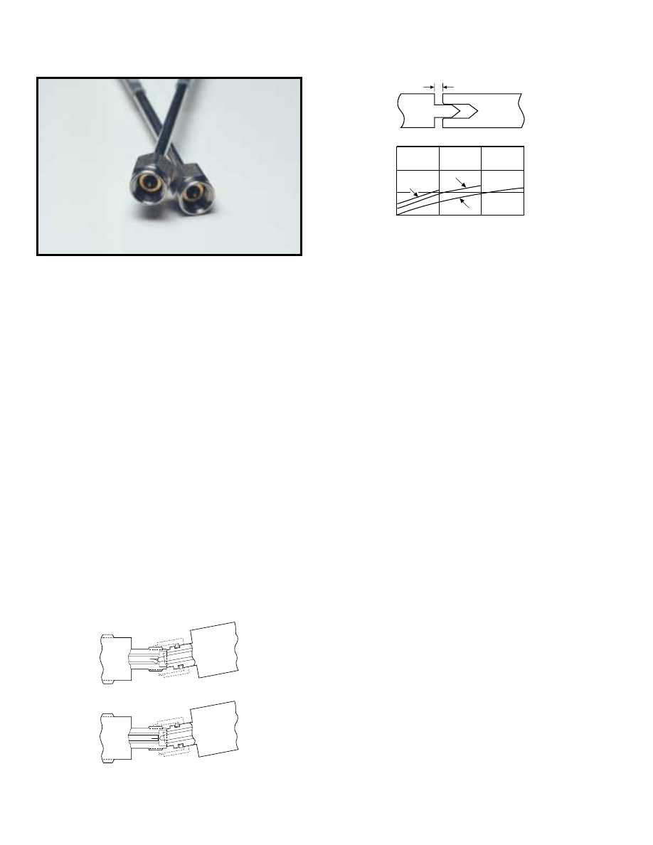
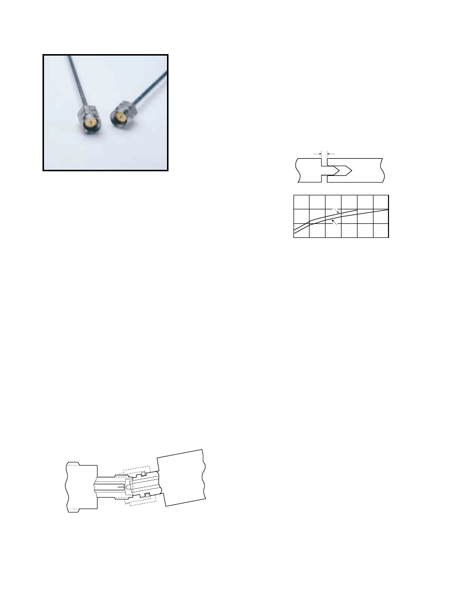
The effect of pin gap on a connection is often overlooked, but is the
dominant source of error in many connection systems. Pin gap is
the short length of smaller diameter caused when a connector pair
is mated. Pin gap causes a discontinuity at the connector interface.
The K Connector has considerably less susceptibility to pin gap than
either SMA or 3.5 mm connectors.
Many connector manufacturers specify connector performance
assuming no pin gap, an unrealistic assumption. K Connectors
are specified assuming pin gap to be at its maximum tolerance,
to provide you the assurance of real-world specifications.
Compatibility
The K Connector interfaces electrically and mechanically
with 3.5 mm connectors, including SMA and 3.5 mm without
degradation in performance.
Launcher design
At the heart of the K Connector product line are the launchers.
As their name implies, the launchers “launch” (make the transition)
from a microwave circuit (microstrip, suspended substrate, stripline,
or coplanar waveguide) to a coaxial connector and an outside
transmission line. The key to making the transition without
compromising electrical and mechanical objectives is the glass
bead in the launcher assembly.
SMA
3.5
0
-10
-20
-30
-40
Pin Gap Retur
n Loss (dB)
Frequency (GHz)
20
30
40
K
Pin Gap
Male
Center
Pin
Female
Center
Pin
SMA/APC-3.5
K Connector
Shortened Male Pin Eliminates Damage to Female K Connector
Effect of Pin Gap
For further information about these products and more, contact us at 1-800-ANRITSU or visit www.us.anritsu.com
5
K CONNECTOR
®
DC to 40 GHz
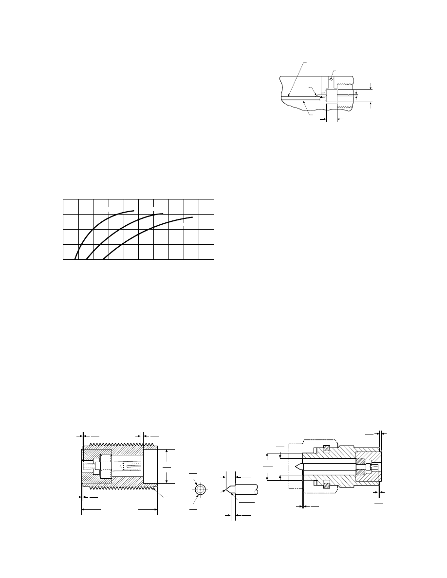
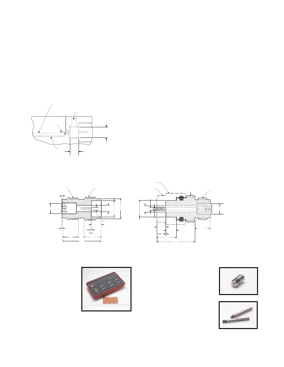
Low-reflection bead
The K Connector
®
’s standard glass bead has a 0.30 mm center
conductor and readily connects to fragile devices. The bead is
appropriate for most applications employing Duroid
®
and ceramic
(Alumina) microstrip, such as the 0.25 mm wide transmission line
on a 0.25 mm thick Alumina substrate. Applications using
suspended substrate geometry are equally well satisfied. The bead
is constructed of Corning 7070 glass and has a gold-plated center
conductor and a gold-plated Kovar
®
collar.
The outstanding design of the bead is largely accountable for the
excellent performance of the K Connector launchers. Because the
small 0.30 mm pin introduces minimal discontinuity, return loss is
typically better than 20 dB at 40 GHz and better than 25 dB below
18 GHz. In addition, the design provides for soldering the bead
to achieve a hermetic seal. 310°C max. soldering temperature
is recommended.
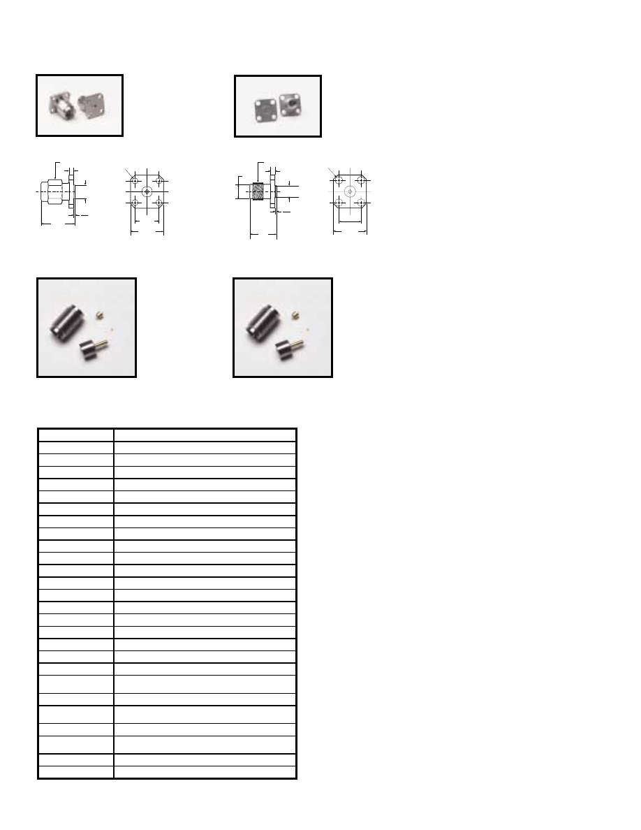
Both the sparkplug (screw-in) and the flange-mount K Connector
launchers offer an additional advantage over existing designs. These
launchers do not use an epoxy pin to secure the center conductor, as
used in some SMA designs. Without an epoxy pin, the outer
conductor remains solid, and thereby eliminates the leakage path
common to pin-captivated designs. Furthermore, K launchers have a
wall thickness that is four times that of typical launchers (0.8 vs.
0.2 mm). The heavier wall results in superior resistance to over-
torquing. Finally, the K Connector launcher can be removed for
repair without removal of the glass bead. This ensures that during
removal the critical microcircuit-to-glass bead interface is not
disturbed, hermeticity is preserved, and the micro-circuit will not be
subjected to the additional stress caused by heating to soldering
temperature. Hardware locking compound such as “Removable
Loctite
®
” should be used to further secure the screw-in launcher in
its housing.
Complete family
Virtually every interface need can be satisfied by one or more of
the K Connector items offered. There are six different models of
K Connector launchers. Two sparkplug (screw-in) launchers are
available, the K102F female version and the K102M male version.
Both screw into the housing that encloses the microwave circuit,
and, like all Anritsu launchers, they can be easily removed for
replacement or repair without unsoldering the glass bead and its
interface to the microwave circuit.
When the housing that encloses the microwave circuit is not thick
enough to support a threaded, screw-in launcher, flush-mounted
(flange) launchers are required. Models with two mounting holes
are available in both male and female versions, K103M and K103F.
Two other models, the K104F and K104M, have four mounting
holes. Mounting hole spacing is identical to that of similar SMA
flange launchers. The glass bead interface, of course, is the same
design used for the sparkplug launcher.
Cable connectors
Both male and female cable connectors are available. The cable
connectors, K101M and K101F, use gold-plated, beryllium-
copper center conductors for optimum performance and wear
characteristics, Typical return loss at 40 GHz for finished cables
exceeds 16 dB (1.35 SWR).
0.00
0.10
4.52
4.57
2.90
2.93
0.13
0.28
0.00
0.10
0.00
0.13
0.00
0.13
1.02
1.12
0.90
0.93
0.40 R
BLEND
4.60
4.65
1.25
1.28
1.47
1.73
0.15
0.31
10.3 NORMAL
0.203 R
FEMALE
MALE
UNS-2A THD
1
x 36
4
K Connector
®
interface dimensions in metric measurements
Frequency (GHz)
Retur
n Loss (dB)
25
30
35
40
45
0
4
8
12
16
24
20
28
32
36
40
WSMA + K
3.5 mm + K
SMA + K
Return Loss Characteristics
Solder
Solder
or Bond
Solder
0.30 mm
1.42 mm
1.98 mm
±
0.03
Bead
Microstrip, Coplanar
Waveguide, Suspended Substrate
+0.08
–0.00
Transition from Microcircuit to External Transmission Line
For further information about these products and more, contact us at 1-800-ANRITSU or visit www.us.anritsu.com
6
K CONNECTOR
®
DC to 40 GHz
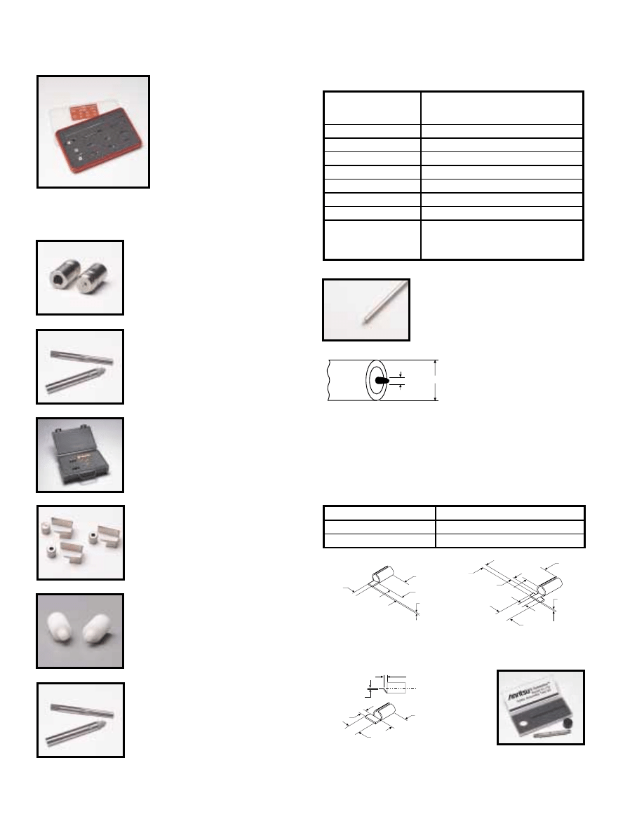
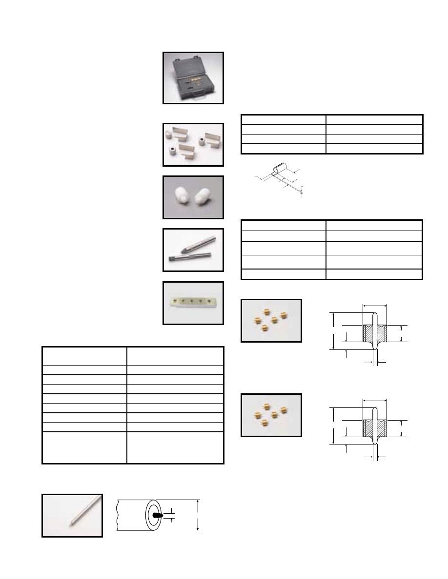
Evaluation kit
01-101A
Evaluation Kit
Kit contains one K120 25 cm Male/Male
Cable Assembly, two K102F Female
Sparkplug Launcher Connector
Assemblies, two K104F Female Flange
Launcher Connector Assemblies, five
K100 Glass Beads, one 01-102A Test
Fixture, one 01-104 Drill and Tap Set,
five K110-1 Microstrip Sliding Contacts,
and all other parts and fixtures required
to assemble launchers with or without
sliding contacts.
01-104
Drill and Tap Set
for precision machining of concentric holes for
mounting K Connector
®
in microwave housing.
(Drill Part No. B14094) (Tap Part No. 783-255)
01-105A
Male and Female Sparkplug Torquing Kit
01-106
K Soldering Fixture for flange launcher
glass bead, package of 5.
01-107M or 01-107F
Cable Sleeve Soldering Fixture for K101M Male
and K101F Female Cable Connectors,
package of 10.
01-108
Drill and Tap Set
For precision machining of concentric holes for
mounting K Connector
®
in microwave housing in
applications where stress relief contacts are used.
(Drill Part No. B16526) (Tap Part No. 783-255)
01-118
K Connector
®
Cable
Assembling Fixture Kit
for K118 semi-rigid
coaxial cable.
3.00
0.81
Dimensions in millimeters
K118
Semi-rigid Coaxial Cable
1.5m length of 3.00 mm semi-rigid cable
for K101 series connector
Stress relief contacts
Stress Relief Contacts provide an elegant yet simple solution
to relieving stress at the interface of the microcircuit and its
connecting coaxial conductor. These contacts simply slide onto
the standard K100 and K100B glass bead pins.
0.150
0.710
0.300
0.040
±
0.010
Dimensions in millimeters
0.300
0.410
0.710
0.10 INSTL.
0.040
±
0.010
Dimensions in millimeters
0.040
±
0.010
0.710
0.300
0.200
0.410
Dimensions in millimeters
K110-1
➀
Microstrip and Coplanar
Waveguide
K110-3
➀
Microstrip
K110-2
➀
Stripline
Semi-rigid coaxial cable
Tools and fixtures
01-103
Soldering Fixture for sparkplug
launcher glass beads, package of 10
Type
Semi-rigid coaxial, tin-plated copper
outer conductor, silver-plated copper
center conductor.
Impedance
50 ± 2 Ohms
Dielectric type
Microporous Teflon, 0.24 cm diameter
Dielectric constant
1.687
Relative velocity
0.77
Outside diameter
3.00 mm
Center conductor diameter
0.81 mm
Minimum bend radius
0.65 cm
Attenuation
1.6 dB/m at 10 GHz
2.3 dB/m at 20 GHz
3.3 dB/m at 30 GHz
4.7 dB/m at 40 GHz
Frequency range
DC to 40 GHz
Material
0.025 mm heat-treated BeCu
Plating
Bondable gold over nickel
➀
Use with 01-108 Drill and Tap Set
For further information about these products and more, contact us at 1-800-ANRITSU or visit www.us.anritsu.com
7
K CONNECTOR
®
DC to 40 GHz
3.18
0.74
1.40
1.93
0.300 DIA.
Dimensions in millimeters
3.18
0.74
1.40
1.93
0.300 DIA.
Dimensions in millimeters
K100
➀➁
Glass Beads for
K102, K103, and
K104 connectors
K100B
➀➁
High Hermeticity* Glass
Beads for K102, K103,
and K104 connectors
7.9 HEX
3.04 for K101M
2.26 for K101M-085
4.55 for K101M
3.05 for K101M-085
8.4
10.9
Dimensions in millimeters
K101M
➃
K Male In-Line Cable
Connector, DC-40 GHz
for 0.118 cable
K101M-085
➃
for 0.085 cable
7.9 HEX
3.04
4.67
10.9
12.9
1
/
4 - 36 THD
Dimensions in millimeters
K101F
➄
K Female In-Line Cable
Connector, DC-40 GHz for
0.118 cable
7.9 HEX
16.2
12.0
4.65
5.33
1
/
4 - 36 THD
0.13
0.28
Dimensions in millimeters
K102M
➂
K Male Sparkplug
Launcher Connector,
DC-40 GHz
0.15
0.30
1/4 - 36 THD
10.4
Dimensions in millimeters
4.65
5.33
∅
5.33
K102F
➂
K Female Sparkplug
Launcher Connector,
DC-40 GHz
*Glass Bead Hermeticity Spec: Hermetic to 1 x 10⁻⁸ std cc He/sec at 1 atm differential
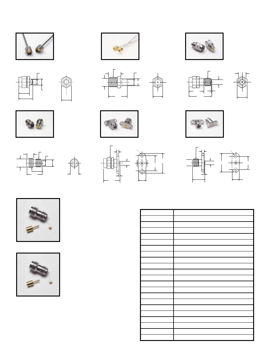
12.2
5.7
15.9
2.6 DIA. (2 PLACES)
9.6
4.14
1.7
0.05
0.20
1
/
4 - 36 THD
Dimensions in millimeters
∅
5.33
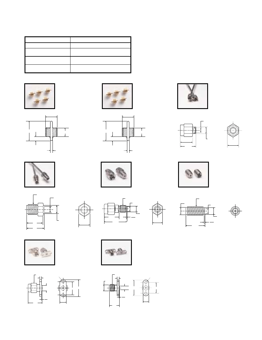
K103F
K Female Flange
Launcher, two-hole,
DC-40 GHz
Launchers and cable connectors
6.60
15.9
12.2
2.6 DIA. (2 PLACES)
13.1
4.14
1.7
0.05
0.20
7.9 HEX
Dimensions in millimeters
K103M
K Male Flange Launcher,
two-hole, DC-40 GHz
Return loss (launchers only)
15 dB up to 40 GHz
Coupling nut tightening torque
1.36 N-m max
Material
Passivated stainless steel with heat-treated beryllium
copper center conductors
Pin depth
0.000 to -0.13 mm for male and
female connectors
Temperature range
-55°C to +125°C
(200°C available; contact factory)
➀
Use with 01-104 or 01-108 Drill and Tap Sets
➁
Use with 01-103 or 01-106 Soldering Fixtures
➂
Use with 01-105A Male and Female Sparkplug
Torquing Kit
➃
Use with 01-107M Cable Sleeve Fixture
➄
Use with 01-107F Cable Sleeve Fixture
For further information about these products and more, contact us at 1-800-ANRITSU or visit www.us.anritsu.com
8
K CONNECTOR
®
DC to 40 GHz
2.6 DIA. (4 PLACES)
8.6 TYP
12.7 SQ.
9.6
4.14
1.7
∅
5.33
0.05
0.20
1
/
4 - 36 THD
Dimensions in millimeters
K104F
K Female Flange Launcher,
four-hole, DC-40 GHz
Ordering information
Please specify model/order number, name, and quantity when ordering.
K110-1
K100B
K102F
K202F
Combination of
K102F, K100,
K110-1
K202FB
Combination of
K102F, K100B,
K110-1
K100
K102F
K110-1
13.1
4.14
1.7
0.05
0.20
7.92 HEX
12.7 SQ.
8.6 TYP
2.6 DIA. (4 PLACES)
Dimensions in millimeters
K104M
K Male Flange Launcher,
four-hole, DC-40 GHz
Model/Order No.
Name
01-101A
K Connector
®
(evaluation kit)
01-103
Soldering fixture for sparkplug launcher glass bead
01-104
Drill and tap set
01-105A
Male and female sparkplug torquing kit
01-106
Soldering fixture for flange launcher glass bead
01-107F
Cable sleeve soldering fixture, female connector
01-107M
Cable sleeve soldering fixture, male connector
01-108
Drill and tap set
01-118
Cable assembling fixture for K118 semi-rigid coax cable
K110-1
Microstrip stress relief contact
K110-2
Stripline stress relief contact
K110-3
Microstrip stress relief contact
K100
Glass bead for K102/103/104 connector
K100B
Hermetic glass bead for K102/103/104 connector
K101M
K(m) in-line cable connector, DC to 40 GHz for K118 cable
K101M-085
K(m) in-line cable connector, DC to 40 GHz for V085 cable
K101F
K(f) in-line cable connector, DC to 40 GHz
K102M
K(m) sparkplug launcher connector, DC to 40 GHz
K102F
K(f) sparkplug launcher connector, DC to 40 GHz
K103M
K(m) flange launcher connector, DC to 40 GHz,
2 mounting holes
K103F
K(f) flange launcher connector, DC to 40 GHz, 2 mounting holes
K104M
K(m) flange launcher connector, DC to 40 GHz,
4 mounting holes
K104F
K(f) flange launcher connector, DC to 40 GHz, 4 mounting holes
K118
Coaxial cable, 1.5m of 3.00 mm semi-rigid cable for
K101 series connector
K202F
Combination of K100, K102F, and K110-1
K202FB
Combination of K100B, K102F, and K110-1
For further information about these products and more, contact us at 1-800-Anritsu or visit www.us.anritsu.com
9
V CONNECTOR
®
DC to 65 GHz
The V Connector
®
is a reliable 1.85 mm device that operates up
to 65 GHz. It is compatible with 2.4 mm connectors and is
assembled using procedures that are similar to those used on
K Connectors. It is well suited to applications in components,
systems, or instrumentation.
V Connector
®
features
• Excellent performance up to 65 GHz
• Low VSWR
• Superior reliability
• Low Loss
Exceptional reliability and repeatability
Microwave connector reliability is affected by insertion force, outer
conductor strength, stress relief while mating, and mating
alignment. The V Connector exhibits exceptional performance in all
of these areas.
For proper seating, the V Connector requires only 1/2 the insertion
force of a 2.4 mm connector. The reduced wear on the center
conductor equates to greater reliability. All V Connectors, including
the cable connectors, incorporate another feature that eliminates a
major cause of connector failure; misalignment of the male pin with
respect to the female. To solve the problem, the V Connector male
pin is deliberately made sufficiently short to prevent damage to the
female connector by misalignment. With this arrangement, the outer
housing must be properly aligned prior to the mating of the center
conductors. Thus a proper, non-destructive alignment before mating
is ensured.
The effect of pin gap on a connection is often overlooked, but is
the dominant source of error in many connection systems. Pin gap is
the short length of smaller diameter created when a connector pair
is mated. Pin gap causes a discontinuity at the connector interface.
The V Connector has considerably less susceptibility to pin gap
than 2.4 mm connectors.
Many connector manufacturers specify connector performance
assuming no pin gap, an unrealistic assumption. V Connectors
are specified assuming pin gap to be at its maximum tolerance, to
provide you the assurance of real-world specifications.
-10
-20
-30
-40
Pin Gap Retur
n Loss (dB)
10
20
Frequency (GHz)
30
40
50
60
70
Pin Gap
Male
Center
Pin
Female
Center
Pin
2.4 mm
V
Effect of Pin Gap
V Connector
Shortened Male Pin Eliminates Damage to Female V Connector
Launcher design
At the heart of the V Connector product line are the launchers.
As their name implies, the launchers “launch” (make the transition)
from a microwave circuit (microstrip, suspended substrate, stripline,
or coplanar waveguide) to a coaxial connector and an outside
transmission line. The key to making the transition without
compromising electrical and mechanical objectives is the glass
bead in the launcher assembly.
Low-reflection glass bead
The V Connector’s standard glass bead has a unique 0.23 mm center
conductor and readily connects to fragile devices. The bead is
appropriate for most applications employing Duroid and ceramic
(Alumina) microstrip, such as the 0.25 mm wide center conductor
on a 0.25 mm thick Alumina substrate. Applications using
suspended substrate geometry are equally well satisfied. The bead is
constructed of Corning 7070 glass and has a gold-plated center
conductor and a gold-plated Kovar
®
collar.
The outstanding design of the bead is largely accountable for the
excellent performance of the V Connector launchers. In addition,
the design provides for soldering the bead to achieve a hermetic
seal. 310°C max. soldering temperature is recommended. The
V Connector
®
launchers can be removed for repair without
removal of the glass bead. This ensures that during removal the
critical microcircuit-to-glass bead interface is not disturbed, that
hermeticity is preserved, and that the microcircuit will not be
subjected to the additional stress caused by heating to soldering
temperature. Hardware locking compound such as “Removable
Loctite
®
” should be used to further secure the launcher in
its housing.
Complete family
Anritsu’s family of V Connector
®
products is large and growing.
Virtually every interface need can be satisfied by one or more of the
items offered. As a convenience to the design engineer, each item is
completely specified with both guaranteed and typical performance.
There are four different models of V Connector launchers. Two
types of sparkplug (screw-in) launchers are available; the V102F
female version and the V102M male version. Both screw into the
housing that encloses the microwave circuit. And, like all Anritsu
launchers, they can be easily removed for replacement or repair
without unsoldering the glass bead and its interface to
the microwave circuit.
For further information about these products and more, contact us at 1-800-Anritsu or visit www.us.anritsu.com
10
V CONNECTOR
®
DC to 65 GHz
Solder
Solder
or Bond
Solder
Bead
Microstrip, Coplanar
Waveguide, Suspended Substrate
1.42 mm
1.78 mm
±
0.02
+0.08
–0.00
Transition from Microcircuit to Outside Transmission Line
FEMALE
MALE
M6.0 x 0.75 - 6G
M7.0 x 0.75 - 6G
M6.0 x 0.75 - 6G
1.85 DIA.
∅
1.85
5.8 DIA.
±
0.1
∅
0.5
3.18 DIA.
4.77 DIA.
∅
4.7
∅
3.18
∅
3.18
FLATS 7.1
0.8 DIA.
∅
0.8
∅
7.7
0.05
3.0
5.0
10.8
5.6
2.1
7.9 HEX
3.4
4.4
3.8
0.10
TYP BOTH
M + F
11.5
0.00
0.10
0.00
0.10
Dimensions in millimeters
V Connector interface dimensions
Evaluation kit
01-301
V Connector Evaluation Kit contains
one V120MM - 25CM Male/Male
Cable Assembly, two V102F Female
Sparkplug Launcher Connector
Assemblies, two V103F Female Flange
Launcher Connector Assemblies, two
V101M Male In-line Cable Connector
Assemblies, five V100 Glass Beads,
one 01-304 Drill and Tap Set, one
01-302 Test Fixture, two 01-303
Soldering Fixtures.
Tools and fixtures
01-303
Soldering Fixture for sparkplug launcher
glass beads, package of 10.
01-304
Drill and Tap Set for precision machining of
concentric holes for mounting V Connector
in microwave housing. (Drill Part No. 783-568)
(Tap Part No. 783-569)
When the housing that encloses the microwave circuit is not thick
enough to support a threaded, screw-in launcher, flush-mounted
(flange) launchers are required. Models with two mounting holes
are available in both male and female versions, V103M and V103F.
The mounting hole spacing is identical to that of similar SMA
flange launchers. The glass bead interface, of course, is the same
design used for the sparkplug launcher.
Cable connectors
To complement high performance V085 cable, both male and female
cable connectors are available. Typical return loss at 60 GHz for
finished cables exceeds 16 dB (1.35 SWR).
The V Connector
®
coaxial cable connectors use a 2.16 mm cable
with a microporous Teflon dielectric and a copper center conductor.
The cable assemblies use the center conductor of the coax as the
male pin. This is similar to the UT-141 SMA-type assembly and
2.4 mm cable assemblies. The microporous Teflon dielectric has
maximum phase stability and minimum insertion loss. This type
of cable assembly allows for easy assembly and maximum RF
performance; however, since the male pin is copper, the cable
assemblies are not suitable for repeated connections. In applications
where the cable will be subject to more than 100 connections,
we recommend that a connector saver be used.
For further information about these products and more, contact us at 1-800-Anritsu or visit www.us.anritsu.com
11
V CONNECTOR
®
DC to 65 GHz
01-105A
K and V Connector
®
Male and Female
Sparkplug Torquing Kit.
Semi-rigid coaxial cable
Launchers and cable connectors
V085
semirigid coaxial cable
1.5m length of 2.16 mm semirigid cable for V101 series connector
2.16
0.51
Dimensions in millimeters
2.79
1.40
1.72
0.240 DIA.
0.60
Dimensions in millimeters
V100
➀➁
Glass Beads for V102,
and V103 connectors
(package of 5)
01-309
V Connector Cable Assembling Fixture
for V085 semi-rigid cable.
01-306
Soldering Fixture for flange launcher glass
bead, package of 5.
01-308
Drill and Tap set for precision machining of
concentric holes for mounting V Connector in
microwave housing in applications where
stress-relief contacts are used.
01-307M or 01-307F
Cable Sleeve Soldering Fixture for V101M
Male and V101F Female Cable Connectors,
package of 10.
Stress relief contacts
Stress Relief Contacts provide an elegant yet simple solution
to relieving stress at the interface of the microcircuit and its
connecting coaxial conductor. These contacts simply slide onto the
standard glass bead pins and can be soldered, bonded or parallel-gap
welded to a circuit trace.
0.160
0.640
0.250 mm
0.040
±
0.010
Dimensions in millimeters
V110-1
Microstrip and Coplanar Waveguide
when using the V110-1, use 01-308
Drill and Tap set to make the
required concentric holes.
2.79
1.40
1.72
0.240 DIA.
0.60
Dimensions in millimeters
V100B
➀➁
High Hermeticity*
Glass Beads for V102,
and V103 connectors
(package of 5)
*Glass Bead Hermeticity Spec: Hermetic to 1 x 10⁻⁸ std cc He/sec at 1 atm differential
Frequency range
DC to 67 GHz
Material
0.025 mm heat-treated BeCu
Plating
Bondable gold
Packaging
Lots of 25
Return loss (launchers only)
13 dB up to 60 GHz
Coupling nut tightening torque
1.36 N-m max
Material
Passivated stainless steel with heat-treated
beryllium copper center conductors
Pin depth
0.000 to -0.130 mm for male and
female connectors
Temperature range
-55°C to +125°C
Type
Semi-rigid coaxial, tin-plated copper
outer conductor, silver-plated copper
center conductor.
Impedance
50 ± 2 Ohms
Dielectric type
Microporous Teflon, 0.14 cm diameter
Dielectric constant
1.687
Relative velocity
0.77
Outside diameter
2.16 mm
Center conductor diameter
0.51 mm
Minimum bend radius
0.65 cm
Attenuation
2.3 dB/m at 10 GHz
3.6 dB/m at 20 GHz
4.3 dB/m at 30 GHz
5.2 dB/m at 40 GHz
7.2 dB/m at 60 GHz
➀
Use with 01-303 or 01-306 Soldering Fixtures
➁
Use with 01-304 or 01-308 Drill and Tap Sets
For further information about these products and more, contact us at 1-800-Anritsu or visit www.us.anritsu.com
12
V CONNECTOR
®
DC to 65 GHz
12.2
15.9
5.7
2.6 DIA. (2 PLACES)
M7 x 0.75 - 6G
1.7
∅
3.20
∅
5.8
11.3
0.10
Dimensions in millimeters
V103F
V Female Flange
Launcher, two-hole,
DC-65 GHz
V202F
Combination of
V102F, V100,
V110-1
V202FB
Combination of
V102F, V100B,
V110-1
V110-1
V110-1
V102F
V100
V100B
V102F
Ordering information
Please specify model/order number, name, and quantity when ordering.
2.26
∅
4.06
8.76
10.1
7.9 HEX
Dimensions in millimeters
V101M
➁➃
V Male In-Line Cable
Connector, DC-65 GHz
for V085 cable
7.9 HEX
11.4
M7 x 0.75 - 6G
∅
3.18
2.3 ID
∅
5.8
6.35
Dimensions in millimeters
7.9 HEX
∅
3.20
7.11
0.02
M6 x 0.75 - 6G
15.3
10.8
Dimensions in millimeters
V102M
➀
V Male Sparkplug
Launcher
Connector,
DC-65 GHz
M6 x 0.75 - 6G
M7 x 0.75 - 6G
11.5
4.9
∅
4.83
±
.05
∅
6.9
∅
5.8
∅
3.2
Dimensions in millimeters
V102F
➀
V Female Sparkplug
Launcher Connector,
DC-65 GHz
15.9
12.2
5.7
2.6 DIA. (2 PLACES)
1.7
0.10
12.4
∅
3.20
7.9 HEX
Dimensions in millimeters
V101F
➂➃
V Female In-Line Cable
Connector, DC-65 GHz
for V085 cable
V103M
V Male Flange Launcher,
two-hole, DC-65 GHz
Model/Order No.
Name
01-105A
Male and female sparkplug torquing kit
01-301
V Connector® (evaluation kit)
01-303
Soldering fixture for sparkplug launcher glass bead
01-304
Drill and tap set
01-306
Soldering fixture for flange launcher glass bead
01-307M
Cable sleeve soldering fixture, male connector
01-307F
Cable sleeve soldering fixture, female connector
01-308
Drill and tap set
01-309
Cable assembling fixture
V085
Coaxial cable, 152 cm (5 feet) length of 2.16 mm semi-rigid cable
V100
Glass bead for V102/103 connectors
V100B
Hermetic glass beads for V102/103 connectors
V101M
V(m) in-line cable connector, DC to 65 GHz
V101F
V(f) in-line cable connector, DC to 65 GHz
V102M
V(m) sparkplug launcher connector, DC to 65 GHz
V102F
V(f) sparkplug launcher connector, DC to 65 GHz
V103M
V(m) flange launcher connector, DC to 65 GHz, 2 mounting holes
V103F
V(f) flange launcher connector, DC to 65 GHz, 2 mounting holes
V110-1
Microstrip stress relief contact
V202F
Combination of V100, V102F, and V110-1
V202FB
Combination of V100B, V102F, and V110-1
➀
Use with 01-105A Male and Female Sparkplug Torquing Kit
➁
Use with 01-307M Cable Sleeve Fixture
➂
Use with 01-307F Cable Sleeve Fixture
➃
Use with 01-309 Cable Assembling Fixture
For further information about these products and more, contact us at 1-800-Anritsu or visit www.us.anritsu.com
13
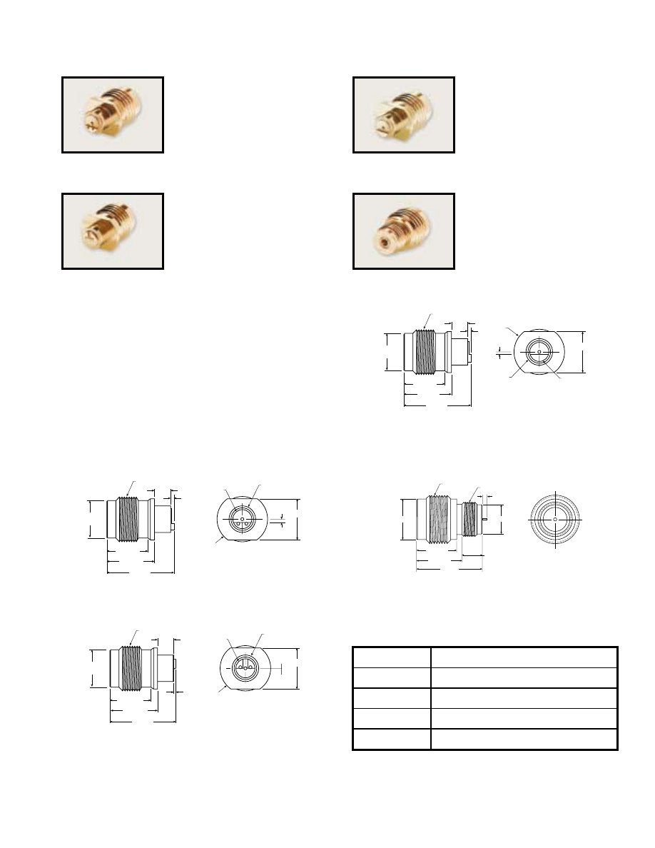
INTEGRATED V CONNECTORS
DC to 65 GHz
The Integrated V Connector
®
family is a group of female
connectors which have the launcher and the glass bead integrated
into one piece. All compensation steps for matching to Microstrip
or Coplanar Waveguide (CPW) are included in the solder-in
hermetic* connectors, ensuring that they deliver excellent
performance. The integrated V connectors come in two easy-to-
install styles: the solder-in version, which is the V115F group,
and the V116F screw-in version, which allows more versatility
of microcircuit launch design. In addition, the V116F can be
soldered in for hermeticity. These connectors, except for the
CPW version, are designed to be used with the V110-1 Stress
Relief Contacts. The Integrated V connectors are compatible with
other V Connectors.
6.41
±
0.10
7.42
±
0.10
.80
2.50
M7 x 0.75 - 6G
R3.94
(10.66)
∅
4.19
±
0.10
∅
5.84
±
0.10
6.40
±
0.05
.418
±
0.05
∅
2.948
±
0.05
V115FMS75
Integrated V Female solder-in
connector, with ground lip, DC
to 65 GHz. Designed for
Microstrip. For use with 0.19
mm (7.5 mil) substrates.
V115FMS75* Outline
6.41
±
0.10
7.42
±
0.10
.50
.02
2.50
M7 x 0.75 - 6G
R3.94
(10.33)
∅
4.19
±
0.10
6.40
±
0.05
∅
2.948
±
0.05
∅
5.84
±
0.10
V115FCPW
Integrated V Female solder-in
connector, with ground lip,
DC to 65 GHz. Designed for
Coplanar Waveguide.
V115FCPW* Outline
6.41
±
0.10
7.42
±
0.10
.80
2.50
M7 x 0.75 - 6G
R3.94
(10.66)
∅
4.19
±
0.10
∅
2.95
±
0.05
∅
5.84
±
0.10
6.40
±
0.05
.597
±
0.05
V115FMS10
Integrated V Female solder-in
connector, with ground lip,
DC to 65 GHz. Designed for
Microstrip. For use with 0.25
mm (10 mil) substrates.
V115FMS10* Outline
2.92
±
0.05
5.78
±
0.10
6.54
±
0.10
(9.46)
∅
4.27
±
0.05
∅
5.84
±
0.10
M7 x 0.75 - 6G
M5 x 0.5 - 6G
.71
±
0.10
V116F
Integrated V Female Sparkplug
(screw-in) connector,
DC to 65 GHz.
V116F* Outline
* Hermeticity specification: 1 x10
-8
std cc He/sec at 1 atm differential.
Ordering information
Please specify model/order number, name and quantity when ordering.
Model/Order No.
Name
V115FMS10
Integrated V(f) solder-in connector for use with 0.25 mm
(10 mil) substrates
V115FMS75
Integrated V(f) solder-in connector for use with 0.19 mm
(7.5 mil) substrates
V115FCPW
Integrated V(f) solder-in connector for Coplanar Waveguide
V116F
Integrated V(f) sparkplug connector
For further information about these products and more, contact us at 1-800-Anritsu or visit www.us.anritsu.com
14
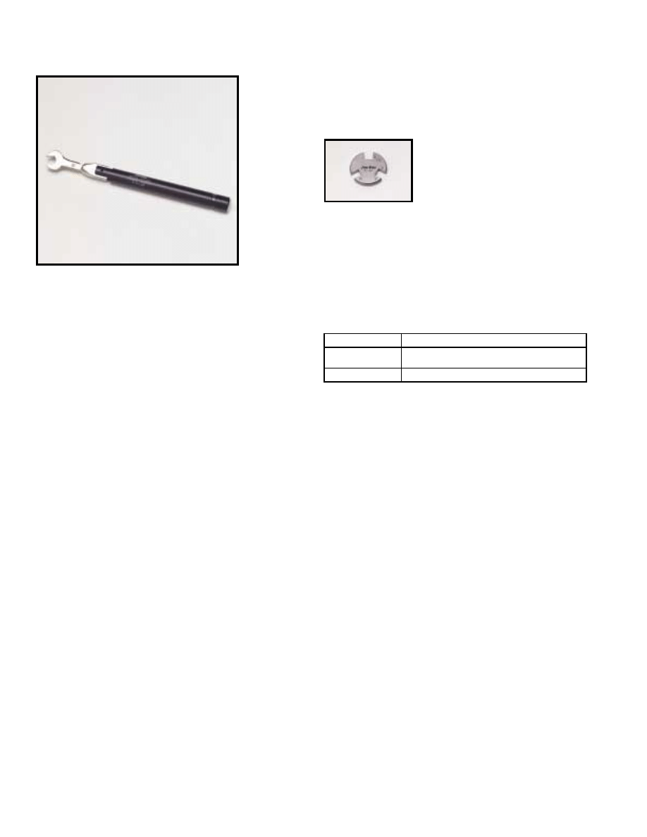
CONNECTOR TOOLS
DC to 65 GHz
Anritsu provides two connector tools that make connecting
and disconnecting tiny connectors more easily and surely
accomplished. These tools are featured below.
Features
• 01-201 Torque wrench: 0.9 N-M (8 in-lb) for
standard SMA and 3.5 mm connectors, and for the
Anritsu K Connector
®
and V Connector
®
.
• 01-204 Handy stainless steel connector wrench for
standard SMA, 3.5 mm, and 2.4 mm connectors, and for
the Anristu K Connector
®
and V Connector
®
.
01-201
01-204
Ordering information
Please specify model/order number, name and quantity when ordering.
Model/Order No.
Name
01-201
Torque wrench, for SMA, 3.5mm, and K Connector and V Connector
01-204
Anritsu stainless steel connector wrench
For further information about these products and more, contact us at 1-800-ANRITSU or visit www.us.anritsu.com
15
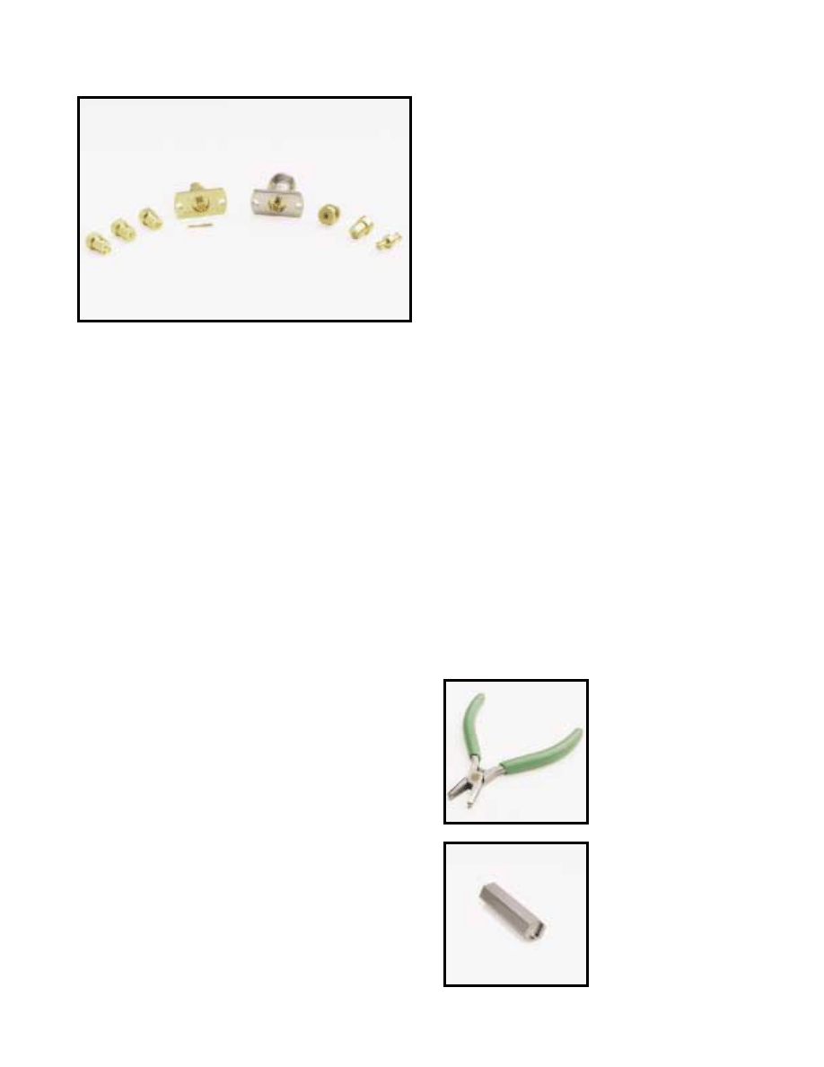
VP™ CONNECTOR
DC to 65 GHz
The new VP Connector family, with shrouds and adapters,
is well suited for applications in components, systems
and instrumentation to 65 GHz. Anritsu’s family of
VP Connectors satisfies virtually every interface and
provides excellent and reliable performance.
VP
™
Connector features
•
Superior RF Performance to 65 GHz
•
Hermetic Connection
•
Sliding Contact Connection to Microstrip
•
Ground lip for handling substrates on carriers
•
Testing capabilities using VP-VF Adapter
•
Auto alignment capabilities on VP-VF Adapters
VP Bullet
The VP Bullet is a VP-VP adapter, designed to connect two
modules with shrouds, back to back. The VP Bullet exhibits
exceptional performance due to it’s unique design concept.
The VP Bullet is designed with six slots in the outer
conductor and four slots in the center conductor. The
increase in the number of slots in the outer conductor
reduces the insertion and extraction force to less than one
half of the force required for conventional SMP connectors
and thus reduces wear and tear. In the lab VP Bullets have
been tested to 1000 insertions with no degradation in
performance. Anritsu guarantees at least 500 connections.
In addition, the VP Bullet provides a positive stop so
that fingers can not be damaged during insertion.
VP Shroud Design
Anritsu VP Shrouds are based on the design concept first
used in Anritsu’s Integrated V Connector
®
. VP Shrouds use
the standard V Glass bead and the critical compensation
steps required to install the glass bead in the housing are
a part of the hermetic shroud design. Since Anritsu controls
the critical internal dimensions, consistent performance
is assured.
Additionally, the ground lip allows the substrate ground to
be attached directly to the connector, eliminating the long
ground path common to other connector families. This short
ground path improves return loss performance, especially
at the high end of the frequency range.
The VP Shrouds, except for the CPW version, are designed
to be used with the Anritsu V110-1 Stress Relief Contact
(sliding contact). The CPW Shrouds backside interface is a
pin overlap design, so the center pin is directly connected to
the transmission line and the substrate ground is directly
attached to the ground lip.
Cable Connector
The VP Cable connector uses standard semi-rigid 2.16 mm
cable just like the V cable Connectors. One can install a
standard V Cable connector on the opposite end which
makes the testing of modules much easier. The VP cable
connector has a flange to ensure a rigid connection to
the module. The cable connectors can also be utilized for
connecting two modules back to back.
VP-VF Adapters
VP-VF Adapters are specifically designed for testing
the modules using the Precision V Connector. The
VP-VF Adapter can be replaced with a VP Bullet
or VP Cable Connector.
01-501
Bullet Insertion
and Removal Tool
01-502
Torque
screwdriver
adapter
For further information about these products and more, contact us at 1-800-ANRITSU or visit www.us.anritsu.com
16
VP™ CONNECTOR
DC to 65 GHz
VP100BCPW
Solder-in CPW
hermetic shroud
Ø4.06
3.62
4.94
1.72
Ø3.18
.76
.02
0.24
2X Ø.50
1.53
All dimensions in mm
.38
VP100B
Screw-in hermetic shroud
4.15
.57
3.57 ACROSS FLTS
Ø4.02
Ø4.02
Ø.24
All dimensions in mm
VP100BMS10
Solder-in
10 mil Microstrip
hermetic shroud
3.62
Ø4.06
Ø3.18
1.72
5.26
2X Ø.50
1.6
.58
.51
0.24
All dimensions in mm
VP101F
VP cable adapter
1.24
10.11
2X R6.35
5.1
2X Ø1.60
Ø3.00
Ø5.33
5.18
10.24
1.6
6.35
All dimensions in mm
VP100BMS75
Solder-in 7.5 mil
Microstrip hermetic
shroud
3.62
Ø4.06
.42
Ø3.18
1.72
5.26
.51
0.24
All dimensions in mm
VP102F
VP Bullet
2.62
6.50
Ø3.05
Ø1.93
Ø1.51
All dimensions in mm
VP100BNL
No lip hermetic
shroud
4.75
1.02
Ø4.06
Ø3.18
Ø.63
0.24
All dimensions in mm
VP103F
VP-VF Adapter
5.1
10.24
1.24
11.84
1.6
6.65
10.11
3.33
2X Ø1.60 THRU
Ø5.84
Ø5.33
M7 X .75
All dimensions in mm
For further information about these products and more, contact us at 1-800-ANRITSU or visit www.us.anritsu.com
17
VP™ CONNECTOR
DC to 65 GHz
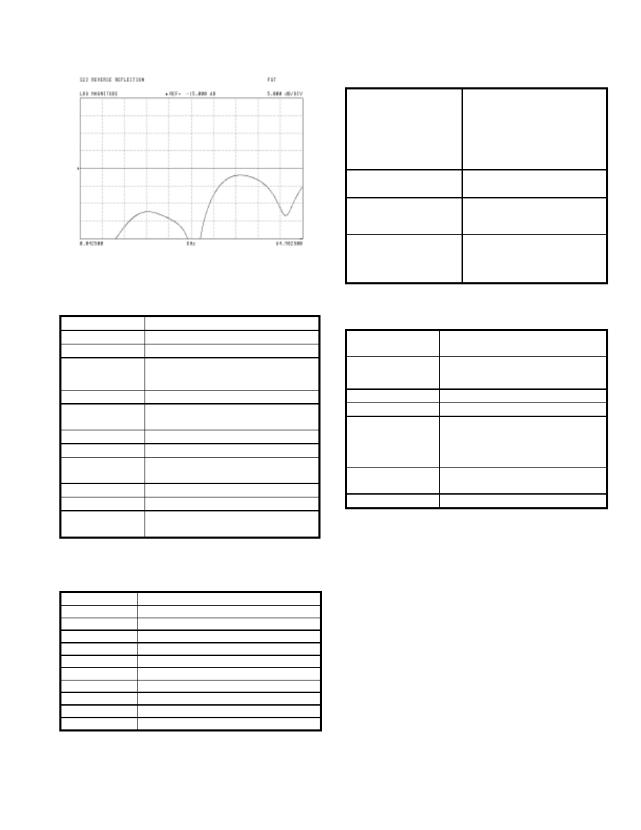
Typical High Frequency Return-Loss measured on V102F over the range
of 40 MHz to 65 GHz.
Specifications:
Impedance
50 Ohms
Frequency
DC to 65 GHz
Insertion Loss
0.05
√
f (GHz)
VSWR:
1.1:1 to 26.5 GHz typical;
1.22:1 to 50 GHz typical;
1.5:1 to 65 GHz typical
Insulation Resistance
> 1200 M
Ω
Center conductor
contact resistance
6 m
Ω
typical
Force to engage
4.2 N typical (1 lbf typical)
Force to disengage
7 N typical. (1.5 lbf typical)
Center contact
Retention
83 N typical. (18 lbf typical)
Radial Misalignment
0.25 mm (0.010”)
Axial Misalignment
0-0.15mm (0 to 0.006”)
Hermeticity
1 x10⁻⁸ std cc He/sec at 1
atmosphere differential for all shrouds
Materials:
Shrouds, VP100B, VP100BCPW,
VP100BMS10, VP100BMS75
and VP100BNL
Material: Brass, gold plated over nickel per
Mil-G-45204C
Center pin: Kovar, gold plated over nickel per
Mil-G-45204C
Bead body: Kovar, gold plated over nickel per
Mil-G-45204C
Bead dielectric: Corning 7070 glass
VP101F VP Cable adapter
Beryllium-copper, gold plated over nickel per
Mil-G-45204C
VP102F VP Bullet
Heat treated Beryllium-copper,
Gold plated over nickel per Mil-G-45204C
Dielectric: Polyphenylene Oxide Noryl (PPO)
VP103F
VP-VF adapter
Body: Passivated stainless steel
Bead: Polyphenylene Oxide Noryl (PPO)
Center conductor: Beryllium-copper,
gold plated over nickel per Mil-G-45204C
Operating
Temperature Range
–54° to +200° C for VP100BXXXX, –54°C to +125°C for VP102F,
VP101F and VP103F adapter
Temperature Shock
25° C to –55° C and 25° C to +200° C, method 107G, Condition
B for shrouds to +125°C for bullet
and cable adapter
Humidity
95% at 40°C, 96 hours, Test 103B, Condition B
Shock
100 G peak sawtooth, method 213, test condition 1
Vibration
Sinewave: 10 Hz to 2000 Hz, 0.06” DA, method 204,
test condition D
Random: 50 Hz to 2000 Hz, 11.6 Grms, Power Spectral Density
0.1 Grms2/Hz,
Method 214, Test Condition I, Letter D
Salt Spray
5% concentration for 48 hours,
Method 101D, Condition B
Voltage withstanding
500 Vac RMS, 60 seconds, method 301
Environmental Information:
Tests are performed per MIL-STD-202F
Model/Order No.
Name
VP100BCPW
Solder-in CPW hermetic shroud
VP100BMS10
Solder-in 10 mil microstrip hermetic shroud
VP100BMS75
Solder-in 7.5 mil microstrip hermetic shroud
VP100BNL
No lip hermetic shroud
VP100B
Screw-in hermetic shroud
VP101F
VP cable adapter
VP102F
VP bullet
VP103F
VP-VF adapter
01-501
Bullet insertion and removal tool
01-502
V100B Torque tool adapter
Ordering information
Please specify model/order number, name, and quantity when ordering.
For further information about these products and more, contact us at 1-800-Anritsu or visit www.us.anritsu.com
18
RF CABLES
K120, V120 DC to 65 GHz
Semi-rigid RF cable features
• Up to 65 GHz frequency ranges
• Type N, K Connector®, and V Connector®
• K Connector® compatibility with SMA and 3.5 mm
• V Connector® compatibility with 2.4 mm
Specifications
K120
V120
Semi-rigid coaxial cable specifications for
K Connectors
®
Contact the Anritsu Company for low loss, low VSWR cable
bending services.
Semi-rigid coaxial cable specifications
for V Connectors
®
Temperature range: –55°C to +125°C
Model
Frequency
range
(GHz)
Impedance
(Ohms)
Length
Connectors
N120-6
DC to 18
50
15 cm
N(m) - N(m)
NS120MF-6
DC to 18
50
15 cm
N(m) - SMA(f)
K120MM
DC to 40
50
See table
K(m) - K(m)
K120MF
DC to 40
50
See table
K(m) - K(f)
K120FF
DC to 40
50
See table
K(f) - K(f)
V120MM
DC to 65
50
See table
V(m) - V(m)
V120MF
DC to 65
50
See table
V(m) - V(f)
V120FF
DC to 65
50
See table
V(f) - V(f)
Type
Semi-rigid coaxial, tin-plated copper
outer conductor, silver-plated copper
center conductor.
Impedance
50 ± 2
Ω
s
Dielectric type
Microporous Teflon, 0.24 cm diameter
Dielectric constant
1.687
Relative velocity
0.77
Outside diameter
3.00 mm
Center conductor diameter
0.81 mm
Minimum bend radius
0.65 cm
Attenuation
1.6 dB/m at 10 GHz
2.3 dB/m at 20 GHz
3.3 dB/m at 30 GHz
4.7 dB/m at 40 GHz
K118 semirigid coaxial cable
1.52 m length of 3.00 mm
Semirigid cable for K101 series connector
Type
Semi-rigid coaxial, tin-plated copper
outer conductor, silver-plated copper
center conductor.
Impedance
50 ± 2
Ω
s
Dielectric type
Microporous Teflon, 0.14 cm diameter
Dielectric constant
1.687
Relative velocity
0.77
Outside diameter
2.18 mm
Center conductor diameter
0.51 mm
Minimum bend radius
0.65 cm
Attenuation
2.3 dB/m at 10 GHz
3.6 dB/m at 20 GHz
4.3 dB/m at 30 GHz
5.2 dB/m at 40 GHz
7.2 dB/m at 60 GHz
For further information about these products and more, contact us at 1-800-Anritsu or visit www.us.anritsu.com
19
RF CABLES
K120, V120 DC to 65 GHz
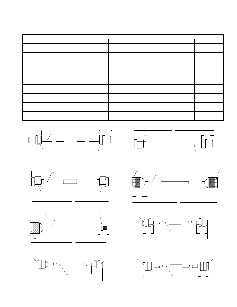
Cable assembly part number reference
13.0 mm
13.0 mm
(1/4-36 UNS-2A)
(1/4-36 UNS-2A)
XXXXXX
"L"
K101F
K118
K101F
Dimensions in Millimeters
K120FF outline
V120FF outline
V120MM outline
V120MF outline
11.0 mm
13.0 mm
"L"
XXXXXX
K118
K101F
(1/4-36 UNS-2A)
K101M
(1/4-36 UNS-2B)
7.9 mm HEX
Dimensions in Millimeters
11.4 mm
11.4 mm
V085
XXXXXX
V-FEMALE
V-FEMALE
"L"
Dimensions in Millimeters
V-FEMALE
V-MALE
"L"
V085
11.4 mm
11.3 mm
XXXXXX
Dimensions in Millimeters
V-MALE
V-MALE
"L"
XXXXXX
V085
11.3 mm
11.3 mm
Dimensions in Millimeters
K120MF outline
(1/4-36 UNS-2B)
(1/4-36 UNS-2B)
XXXXXX
"L"
11.0 mm
11.0 mm
K101M
K101M
K118
Dimensions in Millimeters
K120MM outline
"L"
12.7 mm
XXXXXX
29 mm
semi-rigid
SMA Female
3.58 mm
N Male
Dimensions in Millimeters
NS120MF-6 outline
XXXXXX
29 mm
29 mm
"L"
3.58 mm semi-rigid
N Male
N Male
Dimensions in Millimeters
N120-6 outline
Length
Metric cable assemblies
cm
K120MM
K120MF
K120FF
V120MM
V120MF
V120FF
5
K120MM-5CM
K120MF-5CM
K120FF-5CM
V120MM-5CM
V120MM-5CM
V120FF-5CM
10
K120MM-10CM
K120MF-10CM
K120FF-10CM
V120MM-10CM
V120MM-10CM
V120FF-10CM
15
K120MM-15CM
K120MF-15CM
K120FF-15CM
V120MM-15CM
V120MM-15CM
V120FF-15CM
20
K120MM-20CM
K120MF-20CM
K120FF-20CM
V120MM-20CM
V120MM-20CM
V120FF-20CM
25
K120MM-25CM
K120MF-25CM
K120FF-25CM
V120MM-25CM
V120MM-25CM
V120FF-25CM
30
K120MM-30CM
K120MF-30CM
K120FF-30CM
V120MM-30CM
V120MM-30CM
V120FF-30CM
35
K120MM-35CM
K120MF-35CM
K120FF-35CM
V120MM-35CM
V120MM-35CM
V120FF-35CM
40
K120MM-40CM
K120MF-40CM
K120FF-40CM
V120MM-40CM
V120MM-40CM
V120FF-40CM
45
K120MM-45CM
K120MF-45CM
K120FF-45CM
V120MM-45CM
V120MM-45CM
V120FF-45CM
50
K120MM-50CM
K120MF-50CM
K120FF-50CM
V120MM-50CM
V120MM-50CM
V120FF-50CM
60
K120MM-60CM
K120MF-60CM
K120FF-60CM
V120MM-60CM
V120MM-60CM
V120FF-60CM
70
K120MM-70CM
K120MF-70CM
K120FF-70CM
V120MM-70CM
V120MM-70CM
V120FF-70CM
80
K120MM-80CM
K120MF-80CM
K120FF-80CM
V120MM-80CM
V120MM-80CM
V120FF-80CM
90
K120MM-90CM
K120MF-90CM
K120FF-90CM
V120MM-90CM
V120MM-90CM
V120FF-90CM
100
K120MM-100CM
K120MF-100CM
K120FF-100CM
V120MM-100CM
V120MM-100CM
V120FF-100CM
125
K120MM-125CM
K120MF-125CM
K120FF-125CM
V120MM-125CM
V120MM-125CM
V120FF-125CM
150
K120MM-150CM
K120MF-150CM
K120FF-150CM
V120MM-150CM
V120MM-150CM
V120FF-150CM
For further information about these products and more, contact us at 1-800-Anritsu or visit www.us.anritsu.com
RF CABLES
K120, V120 DC to 65 GHz
Ordering information
Please specify model/order number, name and quantity when ordering.
Model/Order No.
Name
Cable, semi-rigid
N120-6
001 to 18 GHz, 50
Ω
, 15 cm, N(m) to N(m)
NS120MF-6
0.01 to 18 GHz, 50
Ω
, 15 cm, N(m) to SMA(f)
K120MM-5CM
DC to 40 GHz, 50
Ω
, 5 cm, K(m) to K(m)
K120MM-10CM
DC to 40 GHz, 50
Ω
, 10 cm, K(m) to K(m)
K120MM-15CM
DC to 40 GHz, 50
Ω
, 15 cm, K(m) to K(m)
K120MM-20CM
DC to 40 GHz, 50
Ω
, 20 cm, K(m) to K(m)
K120MM-25CM
DC to 40 GHz, 50
Ω
, 25 cm, K(m) to K(m)
K120MM-30CM
DC to 40 GHz, 50
Ω
, 30 cm, K(m) to K(m)
K120MM-35CM
DC to 40 GHz, 50
Ω
, 35 cm, K(m) to K(m)
K120MM-40CM
DC to 40 GHz, 50
Ω
, 40 cm, K(m) to K(m)
K120MM-45CM
DC to 40 GHz, 50
Ω
, 45 cm, K(m) to K(m)
K120MM-50CM
DC to 40 GHz, 50
Ω
, 50 cm, K(m) to K(m)
K120MM-60CM
DC to 40 GHz, 50
Ω
, 60 cm, K(m) to K(m)
K120MM-70CM
DC to 40 GHz, 50
Ω
, 70 cm, K(m) to K(m)
K120MM-80CM
DC to 40 GHz, 50
Ω
, 80 cm, K(m) to K(m)
K120MM-90CM
DC to 40 GHz, 50
Ω
, 90 cm, K(m) to K(m)
K120MM-100CM
DC to 40 GHz, 50
Ω
, 100 cm, K(m) to K(m)
K120MM-125CM
DC to 40 GHz, 50
Ω
, 125 cm, K(m) to K(m)
K120MM-150CM
DC to 40 GHz, 50
Ω
, 150 cm, K(m) to K(m)
K120MF-5CM
DC to 40 GHz, 50
Ω
, 5 cm, K(m) to K(f)
K120MF-10CM
DC to 40 GHz, 50
Ω
, 10 cm, K(m) to K(f)
K120MF-15CM
DC to 40 GHz, 50
Ω
, 15 cm, K(m) to K(f)
K120MF-20CM
DC to 40 GHz, 50
Ω
, 20 cm, K(m) to K(f)
K120MF-25CM
DC to 40 GHz, 50
Ω
, 25 cm, K(m) to K(f)
K120MF-30CM
DC to 40 GHz, 50
Ω
, 30 cm, K(m) to K(f)
K120MF-35CM
DC to 40 GHz, 50
Ω
, 35 cm, K(m) to K(f)
K120MF-40CM
DC to 40 GHz, 50
Ω
, 40 cm, K(m) to K(f)
K120MF-45CM
DC to 40 GHz, 50
Ω
, 45 cm, K(m) to K(f)
K120MF-50CM
DC to 40 GHz, 50
Ω
, 50 cm, K(m) to K(f)
K120MF-60CM
DC to 40 GHz, 50
Ω
, 60 cm, K(m) to K(f)
K120MF-70CM
DC to 40 GHz, 50
Ω
, 70 cm, K(m) to K(f)
K120MF-80CM
DC to 40 GHz, 50
Ω
, 80 cm, K(m) to K(f)
K120MF-90CM
DC to 40 GHz, 50
Ω
, 90 cm, K(m) to K(f)
K120MF-100CM
DC to 40 GHz, 50
Ω
, 100 cm, K(m) to K(f)
K120MF-125CM
DC to 40 GHz, 50
Ω
, 125 cm, K(m) to K(f)
K120MF-150CM
DC to 40 GHz, 50
Ω
, 150 cm, K(m) to K(f)
K120FF-5CM
DC to 40 GHz, 50
Ω
, 5 cm, K(f) to K(f)
K120FF-10CM
DC to 40 GHz, 50
Ω
, 10 cm, K(f) to K(f)
K120FF-15CM
DC to 40 GHz, 50
Ω
, 15 cm, K(f) to K(f)
K120FF-20CM
DC to 40 GHz, 50
Ω
, 20 cm, K(f) to K(f)
K120FF-25CM
DC to 40 GHz, 50
Ω
, 25 cm, K(f) to K(f)
K120FF-30CM
DC to 40 GHz, 50
Ω
, 30 cm, K(f) to K(f)
K120FF-35CM
DC to 40 GHz, 50
Ω
, 35 cm, K(f) to K(f)
K120FF-40CM
DC to 40 GHz, 50
Ω
, 40 cm, K(f) to K(f)
K120FF-45CM
DC to 40 GHz, 50
Ω
, 45 cm, K(f) to K(f)
K120FF-50CM
DC to 40 GHz, 50
Ω
, 50 cm, K(f) to K(f)
K120FF-60CM
DC to 40 GHz, 50
Ω
, 60 cm, K(f) to K(f)
K120FF-70CM
DC to 40 GHz, 50
Ω
, 70 cm, K(f) to K(f)
K120FF-80CM
DC to 40 GHz, 50
Ω
, 80 cm, K(f) to K(f)
K120FF-90CM
DC to 40 GHz, 50
Ω
, 90 cm, K(f) to K(f)
K120FF-100CM
DC to 40 GHz, 50
Ω
, 100 cm, K(f) to K(f)
K120FF-125CM
DC to 40 GHz, 50
Ω
, 125 cm, K(f) to K(f)
K120FF-150CM
DC to 40 GHz, 50
Ω
, 150 cm, K(f) to K(f)
Model/Order No.
Name
Cable, semi-rigid
V120MM-5CM
DC to 65 GHz, 50
Ω
, 5 cm, V(m) to V(m)
V120MM-10CM
DC to 65 GHz, 50
Ω
, 10 cm, V(m) to V(m)
V120MM-15CM
DC to 65 GHz, 50
Ω
, 15 cm, V(m) to V(m)
V120MM-20CM
DC to 65 GHz, 50
Ω
, 20 cm, V(m) to V(m)
V120MM-25CM
DC to 65 GHz, 50
Ω
, 25 cm, V(m) to V(m)
V120MM-30CM
DC to 65 GHz, 50
Ω
, 30 cm, V(m) to V(m)
V120MM-35CM
DC to 65 GHz, 50
Ω
, 35 cm, V(m) to V(m)
V120MM-40CM
DC to 65 GHz, 50
Ω
, 40 cm, V(m) to V(m)
V120MM-45CM
DC to 65 GHz, 50
Ω
, 45 cm, V(m) to V(m)
V120MM-50CM
DC to 65 GHz, 50
Ω
, 50 cm, V(m) to V(m)
V120MM-60CM
DC to 65 GHz, 50
Ω
, 60 cm, V(m) to V(m)
V120MM-70CM
DC to 65 GHz, 50
Ω
, 70 cm, V(m) to V(m)
V120MM-80CM
DC to 65 GHz, 50
Ω
, 80 cm, V(m) to V(m)
V120MM-90CM
DC to 65 GHz, 50
Ω
, 90 cm, V(m) to V(m)
V120MM-100CM
DC to 65 GHz, 50
Ω
, 100 cm, V(m) to V(m)
V120MM-125CM
DC to 65 GHz, 50
Ω
, 125 cm, V(m) to V(m)
V120MM-150CM
DC to 65 GHz, 50
Ω
, 150 cm, V(m) to V(m)
V120MF-5CM
DC to 65 GHz, 50
Ω
, 5 cm, V(m) to V(f)
V120MF-10CM
DC to 65 GHz, 50
Ω
, 10 cm, V(m) to V(f)
V120MF-15CM
DC to 65 GHz, 50
Ω
, 15 cm, V(m) to V(f)
V120MF-20CM
DC to 65 GHz, 50
Ω
, 20 cm, V(m) to V(f)
V120MF-25CM
DC to 65 GHz, 50
Ω
, 25 cm, V(m) to V(f)
V120MF-30CM
DC to 65 GHz, 50
Ω
, 30 cm, V(m) to V(f)
V120MF-35CM
DC to 65 GHz, 50
Ω
, 35 cm, V(m) to V(f)
V120MF-40CM
DC to 65 GHz, 50
Ω
, 40 cm, V(m) to V(f)
V120MF-45CM
DC to 65 GHz, 50
Ω
, 45 cm, V(m) to V(f)
V120MF-50CM
DC to 65 GHz, 50
Ω
, 50 cm, V(m) to V(f)
V120MF-60CM
DC to 65 GHz, 50
Ω
, 60 cm, V(m) to V(f)
V120MF-70CM
DC to 65 GHz, 50
Ω
, 70 cm, V(m) to V(f)
V120MF-80CM
DC to 65 GHz, 50
Ω
, 80 cm, V(m) to V(f)
V120MF-90CM
DC to 65 GHz, 50
Ω
, 90 cm, V(m) to V(f)
V120MF-100CM
DC to 65 GHz, 50
Ω
, 100 cm, V(m) to V(f)
V120MF-125CM
DC to 65 GHz, 50
Ω
, 125 cm, V(m) to V(f)
V120MF-150CM
DC to 65 GHz, 50
Ω
, 150 cm, V(m) to V(f)
V120FF-5CM
DC to 65 GHz, 50
Ω
, 5 cm, V(f) to V(f)
V120FF-10CM
DC to 65 GHz, 50
Ω
, 10 cm, V(f) to V(f)
V120FF-15CM
DC to 65 GHz, 50
Ω
, 15 cm, V(f) to V(f)
V120FF-20CM
DC to 65 GHz, 50
Ω
, 20 cm, V(f) to V(f)
V120FF-25CM
DC to 65 GHz, 50
Ω
, 25 cm, V(f) to V(f)
V120FF-30CM
DC to 65 GHz, 50
Ω
, 30 cm, V(f) to V(f)
V120FF-35CM
DC to 65 GHz, 50
Ω
, 35 cm, V(f) to V(f)
V120FF-40CM
DC to 65 GHz, 50
Ω
, 40 cm, V(f) to V(f)
V120FF-45CM
DC to 65 GHz, 50
Ω
, 45 cm, V(f) to V(f)
V120FF-50CM
DC to 65 GHz, 50
Ω
, 50 cm, V(f) to V(f)
V120FF-60CM
DC to 65 GHz, 50
Ω
, 60 cm, V(f) to V(f)
V120FF-70CM
DC to 65 GHz, 50
Ω
, 70 cm, V(f) to V(f)
V120FF-80CM
DC to 65 GHz, 50
Ω
, 80 cm, V(f) to V(f)
V120FF-90CM
DC to 65 GHz, 50
Ω
, 90 cm, V(f) to V(f)
V120FF-100CM
DC to 65 GHz, 50
Ω
, 100 cm, V(f) to V(f)
V120FF-125CM
DC to 65 GHz, 50
Ω
, 125 cm, V(f) to V(f)
V120FF-150CM
DC to 65 GHz, 50
Ω
, 150 cm, V(f) to V(f)
20
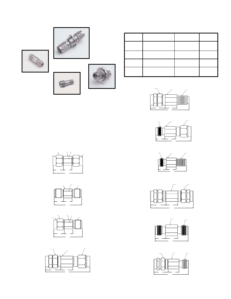
For further information about these products and more, contact us at 1-800-Anritsu or visit www.us.anritsu.com
21
COAXIAL ADAPTERS
K, V, K to V DC to 60 GHz
K230B
V230
K222B
K224B
The K220 and 34V Series of precision adapters enable accurate
measurements with K or V connectors. Every adapter is fully
specified and 100% tested to ensure low reflections and optimum
performance over the DC to 60 GHz range.
Precision K and V adapter features
• K Connector
®
DC to 40 GHz frequency range
• V Connector
®
DC to 60 GHz frequency range
• Low SWR and insertion loss
K220B
7.93 HEX
6.35 DIA.
5.33 ACROSS FLATS
K MALE CONNECTOR
(1/4 - 36 UNS - 2B) 2X
7.0
5.84
20.6
Dimensions in Millimeters
K220B Outline
Specifications
K222B
6.35 DIA.
5.33 ACROSS FLATS
K FEMALE CONNECTOR
(1/4 - 36 UNS - 2A) 2X
7.0
5.84
19.1
Dimensions in Millimeters
K222B Outline
K224B
7.93 HEX
6.35 DIA.
5.33 ACROSS FLATS
K FEMALE CONNECTOR
(1/4 - 36 UNS - 2A)
7.0
5.84
19.8
Dimensions in Millimeters
K MALE CONN.
(1/4 - 36 UNS - 2B)
K224B Outline
31.7
8.64
11
34VK50
Dimensions in Millimeters
7.92 DIA
V-MALE
CONNECTOR
M7.0 X .75 6H
K-MALE
CONNECTOR
(1/4 -36 UNS-2B)
34VK50 Outline
24.4
34VFKF50
8.64
7
VF-FEMALE
CONNECTOR
(M7.0 X .75-6G)
7.92 DIA
KF-FEMALE
CONNECTOR
(1/4-36 UNS-2A)
Dimensions in Millimeters
34VFKF50 Outline
34VV50
31.4
11
8.64
Dimensions in Millimeters
V MALE
CONNECTOR
M7.0 X .75-6H 2X
7.92 DIA
34VV50 Outline
34VFVF50
23.6
7
8.64
7.92 DIA
V FEMALE
CONNECTOR
M7.0 X .75-6G 2X
Dimensions in Millimeter
34VFVF50 Outline
Dimensions in Millimeters
8.64
11
27.5
34VVF50
V MALE CONNECTOR
M7.0 X .75-6H
V FEMALE
CONNECTOR
M7.0 X .75-6G
7.92 DIA
34VVF50 Outline
8.64
11
34VKF50
28.5
Dimensions in Millimeters
7.92 DIA
K-FEMALE
CONNECTOR
(1/4-36 UNS-2A)
V-MALE
CONNECTOR
M7.0 X .75 - 6G
34VKF50 Outline
7
27.8
8.64
34VFK50
7.92 DIA
K-MALE
CONNECTOR
(1/4 -36 UNS-2B)
VF-FEMALE
CONNECTOR
(M7.0 X .75-6G)
Dimensions in Millimeters
34VFK50 Outline
Temperature range: –55°C to +125°C
Model
Frequency range (GHz)
Connectors
SWR
K220B
K222B
K224B
DC to 40
K(m) to K(m)
K(f) to K(f)
K(f) to K(m)
1.12
34VK50
34VKF50
DC to 40
V(m) to K(m)
V(m) to K(f)
1.3
34VFK50
34VFKF50
DC to 40
V(f) to K(m)
V(f) to K(f)
1.3
34VV50
34VFVF50
34VVF50
DC to 60
V(m) to V(m)
V(f) to V(f)
V(m) to V(f)
1.5
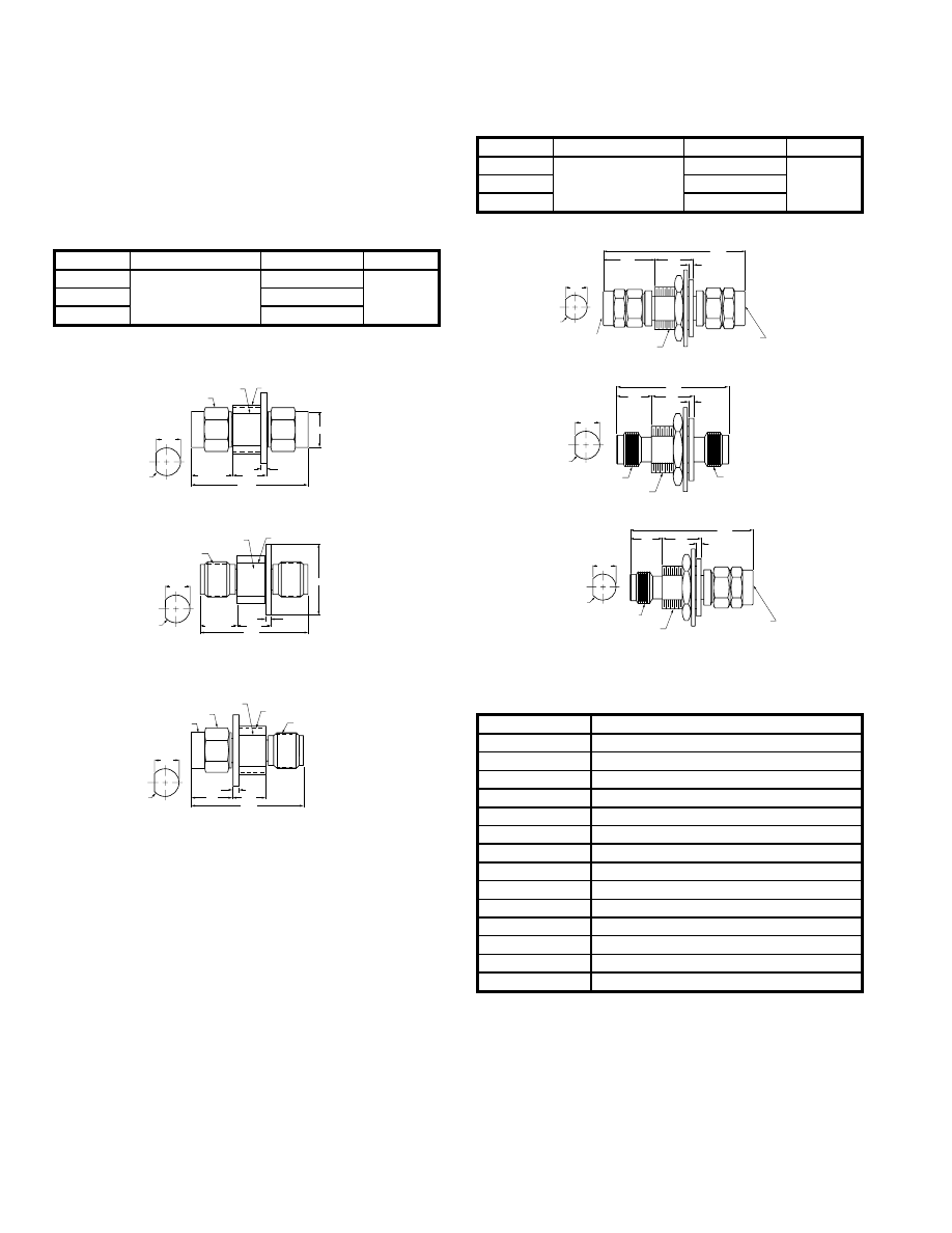
For further information about these products and more, contact us at 1-800-Anritsu or visit www.us.anritsu.com
22
COAXIAL ADAPTERS
K, V, K to V DC to 60 GHz
K-MALE CONNECTOR
(1/4 - 36 UNS - 2B) 2X
8.64 ACROSS FLAT
6.60
±
0.50
5.84
20.6
Dimensions in Millimeters
3/8 - 32 UNEF - 2A
12.7 DIA.
1.02
8.76
9.5 mm
CLEAR
MOUNTING HOLE
K230B Outline
8.64 ACROSS FLAT
3/8 - 32 UNEF-2A
19.1
Dimensions in Millimeters
K FEMALE CONNECTOR
1/4 - 36 UNS-2A 2X
6.67
±
0.50
5.84
1.02
8.76
9.5 mm
CLEAR
MOUNTING HOLE
12.7 DIA.
8.76
9.5 mm
CLEAR
MOUNTING HOLE
19.6
Dimensions in Millimeters
1.02
5.84
7.5
7.92 HEX
8.64 ACROSS FLAT
3/8 - 32 UNEF - 2A
K-MALE CONNECTOR
(1/4 - 36 UNS - 2B)
K FEMALE CONNECTOR
1/4 - 36 UNS-2A
K232B Outline
K234B Outline
The K230 Series is the panel-mount version of the K220 Series
Adapters. These units mount in a standard 9.5 mm “D” hole.
K and V panel adapter features
• Precision, panel-mounted feedthru adapter
• Broad, DC to 65 GHz frequency range
K panel adapter specifications
Ordering information
Please specify model/order number, name and quantity when ordering.
11.56
31.7
1.02
8.64
V MALE CONNECTOR
M7.0 X .75-6G
V MALE CONNECTOR
M7.0 X .75-6H
3/8-32 UNS-2A
8.76
9.5 mm
CLEAR
MOUNTING HOLE
Dimensions in Millimeters
V230 Outline
22.9
7.14
8.64
1.02
3/8-32 UNS-2A
V FEMALE CONNECTOR
M7.0 X .75-6H
V FEMALE CONNECTOR
M7.0 X .75-6G
8.76
9.5 mm
CLEAR
MOUNTING HOLE
Dimensions in Millimeters
7.14
8.64
1.02
27.3
3/8-32 UNS-2A
V FEMALE CONNECTOR
M7.0 X .75-6G
V MALE CONNECTOR
M7.0 X .75-6H
Dimensions in Millimeters
8.76
9.5 mm
CLEAR
MOUNTING HOLE
V232 Outline
V234 Outline
Model
Frequency range (GHz)
Connectors
SWR
K230B
DC to 40
K(m) to K(m)
1.12
K232B
K(f) to K(f)
K234B
K(f) to K(m)
Model
Frequency range (GHz)
Connectors
SWR
V230
DC to 65
V(m) to V(m)
1.5
V232
V(f) to V(f)
V234
V(f) to V(m)
Model/Order No.
Name
Precision adapter
K220B
DC to 40 GHz, 50 Ohm, K(m)-K(m)
K222B
DC to 40 GHz, 50 Ohm, K(f)-K(f)
K224B
DC to 40 GHz, 50 Ohm, K(m)-K(f)
34VK50
DC to 46.5 GHz, 50 Ohm, V(m)-K(m)
34VKF50
DC to 40 GHz, 50 Ohm, V(m)-K(f)
34VFK50
DC to 40 GHz, 50 Ohm, V(f)-K(m)
34VFKF50
DC to 40 GHz, 50 Ohm, V(f)-K(f)
34VV50
DC to 60 GHz, 50 Ohm, V(m)-V(m)
34VVF50
DC to 60 GHz, 50 Ohm, V(m)-V(f)
34VFVF50
DC to 60 GHz, 50 Ohm, V(f)-V(f)
V230
DC to 65 GHz, 50 Ohm, V(m)-V(m)
V232
DC to 65 GHz, 50 Ohm, V(f)-V(f)
V234
DC to 65 GHz, 50 Ohm, V(f)-V(m)
V panel adapter specifications
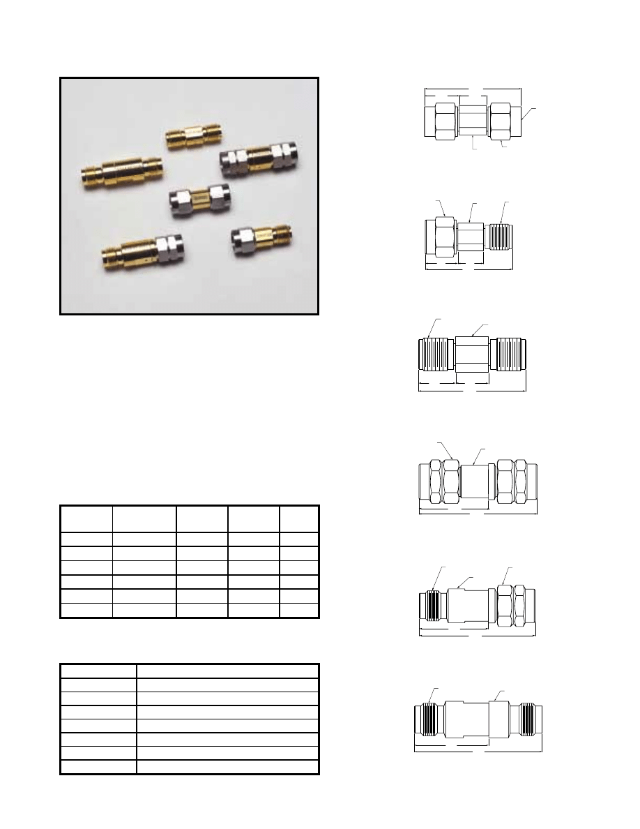
For further information about these products and more, contact us at 1-800-ANRITSU or visit www.us.anritsu.com
23
CALIBRATION GRADE ADAPTERS
33 Series DC to 65 GHz
The 33 Series of precision adapters enable accurate measurements
with Anritsu V Connector
®
and K Connector
®
interfaces. Every
adapter is fully specified and 100% tested to ensure low reflections
and optimum phase performance over a broad frequency range.
Features
• Low SWR and insertion loss
• DC to 65 GHz, with V Connector
®
interface
• DC to 40 GHz, with K Connector
®
interface
• 50
Ω
impedance
Specifications
Temperature range: –55°C to +125°C
Model
Frequency range
(GHz)
Impedance
(Ohms)
Connectors
SWR
33KK50B
DC to 40
50
K(m)-K(m)
1.01
33KKF50B
DC to 40
50
K(m)-K(f)
1.07
33KFKF50B
DC to 40
50
K(f)-K(f)
1.09
33VV50B
DC to 65
50
V(m)-V(m)
1.22
33VVF50B
DC to 65
50
V(m)-V(f)
1.33
33VFVF50B
DC to 65
50
V(f)-V(f)
1.33
Ordering information
Please specify model/order number, name and quantity when ordering.
Model/Order No.
Name
Calibration grade adapter
33KFKF50B
DC to 40 GHz, 50
Ω
, K(f)-K(f)
33KK50B
DC to 40 GHz, 50
Ω
, K(m)-K(m)
33KKF50B
DC to 40 GHz, 50
Ω
, K(m)-K(f)
33VFVF50B
DC to 65 GHz, 50
Ω
, V(f)-V(f)
33VV50B
DC to 65 GHz, 50
Ω
, V(m)-V(m)
33VVF50B
DC to 65 GHz, 50
Ω
, V(m)-V(f)
33KFKF50B
7.0
5.84
19.1
Dimensions in Millimeters
6.35 DIA
K-FEMALE CONNECTOR
(1/4-36 UNS-2A)
2X
33KFKF50B Outline
Dimensions in Millimeters
33VV50B
26.0
15.3
V-MALE CONNECTOR
M7.0 X .75-6H 2X
7.87 DIA
33VV50B Outline
33VVF50B
26.9
16.0
Dimensions in Millimeters
V MALE CONNECTOR
M7 X .75-6H
V-FEMALE CONNECTOR
M7.0 X .750-6G
7.87 DIA
33VVF50B Outline
27.5
16.0
Dimensions in Millimeters
33VFVF50B
V-FEMALE CONNECTOR
M7.0 X .75-6G 2X
7.87 DIA
33VFVF50B Outline
33KKF50B
Dimensions in Millimeters
20.0
7.5
5.84
K-FEMALE CONNECTOR
(1/4-36 UNS-2A)
K-MALE CONNECTOR
(1/4-36 UNS-2B)
6.35 DIA
33KKF50B Outline
5.80
7.5
20.8
33KK50B
K-MALE
CONNECTOR
(1/4-36 UNS-2B)
2X
Ø 6.35
7.90 HEX
2X
Dimensions in Millimeter
33KK50B Outline
33VV50B
33KK50B
33VFVF50B
33KFKF50B
33KKF50B
33VVF50B
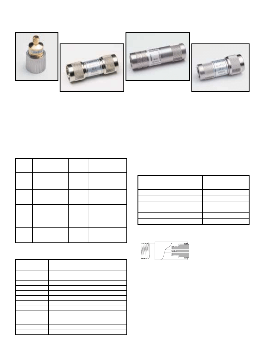
For further information about these products and more, contact us at 1-800-ANRITSU or visit www.us.anritsu.com
24
INSTRUMENTATION GRADE ADAPTERS
34 Series
The 34 Series of precision adapters enable accurate measurements
with GPC-7, Type N, or WSMA interfaces. Every adapter is fully
specified and 100% tested to ensure low reflections and optimum
phase performance over a broad frequency range.
Precision adapter features
• Low SWR and insertion loss
• GPC-7, Type N, and WSMA connectors
• Convenient transition with minimal effect on signal
• 50
Ω
or 75
Ω
impedance
Specifications
The 34R Series precision adapters provide a rugged,
rigid connection between Anritsu instruments with WSMA,
K Connector
®
, or V Connector
®
outputs and Anritsu SWR
Autotesters and SWR Bridges or other instruments.
The adapters have an outside diameter equal to that of a
Type N connector, adding mechanical strength to the test
setup and making installation convenient and fast.
Ruggedized adapter features
• Enhance reliability of microwave test setup
• Easy-to-grasp Type N outside diameter
• Rigid test connections for improved
test data repeatability
Specifications
34RSN50
34RKRK50
34ASF50
34NN50A
Model
Frequency
range
(GHz)
Impedance
(Ohms)
Connectors
SWR
Dimensions
L(cm) x dia(cm)
34NN75B
34NFNF75B
DC to 3
75
N(m) to N(m)
N(f) to N(f)
1.1
6.0 x 2.2
4.7 x 1.6
34AN50
34ANF50
DC to 18
50
GPC-7 to N(m)
GPC-7 to N(f)
1.02
4.2 x 2.2
4.2 x 2.2
34AS50
34ASF50
DC to 18
50
GPC-7 to
WSMA(m)
GPC-7 to
WSMA(f)
1.033
3.8 x 2.2
3.8 x 2.2
34NN50A
34NFNF50
DC to 18
50
N(m) to N(m)
N(f) to N(f)
1.1
6.0 x 2.2
4.7 x 1.6
34NK50
34NKF50
34NFK50
34NFKF50
DC to 18
50
N(m) to K(m)
N(m) to K(f)
N(f) to K(m)
N(f) to K(f)
1.12
3.8 x 2.2
3.8 x 2.2
3.8 x 1.6
3.8 x 1.6
34SFSF50
DC to 26.5
50
WSMA(f) to
WSMA(f)
1.11 to
18.5 GHz
1.18 to
26.5 GHz
1.6 x 0.8
Model
Frequency
range
(GHz)
Connectors
SWR
Dimensions
L(cm) x dia(cm)
34RSN50
DC to 18
RS(m) to N(m)
1.40
5.1 x 2.2
34RKNF50
DC to 18
RK(m) to N(f)
1.40
5.1 x 1.7
34RVNF50
DC to 18
RV(m) to N(f)
1.40
5.1 x 1.7
34RKRK50
DC to 40
RK(m) to RK(m)
2.00
5.8 x 1.7
34RVRK50
DC to 40
RV(m) to RK(m)
2.00
5.8 x 1.7
34RVRV50
DC to 60
RV(m) to RV(m)
2.30
5.8 x 1.7
Impedance: 50 ohms
Temperature range: 0°C to +75°C
Anritsu
Instrument
Connector
34R Series Adapter
Ordering information
Please specify model/order number, name, and quantity when ordering.
Model/Order No.
Name
Precision adapter
34NN75B
DC to 3 GHz, 75
Ω
, N(m)-N(m)
34NFNF75B
DC to 3 GHz, 75
Ω
, N(f)-N(f)
34AN50
DC to 18 GHz, 50
Ω
, GPC-7-N(m)
34ANF50
DC to 18 GHz, 50
Ω
, GPC-7-N(f)
34AS50
DC to 18 GHz, 50
Ω
, GPC-7-WSMA(m)
34ASF50
DC to 18 GHz, 50
Ω
, GPC-7-WSMA(f)
34NN50A
DC to 18 GHz, 50
Ω
, N(m)-N(m)
34NFNF50
DC to 18 GHz, 50
Ω
, N (f)-N(f)
34NK50
DC to 18 GHz, 50
Ω
, N (m)-K(m)
34NKF50
DC to 18 GHz, 50
Ω
, N(m)-K(f)
34NFK50
DC to 18 GHz, 50
Ω
, N (f)-K(m)
34NFKF50
DC to 18 GHz, 50
Ω
, N(f)-K(f)
34SFSF50
DC to 26.5 GHz, 50
Ω
, WSMA(f)-WSMA(f)
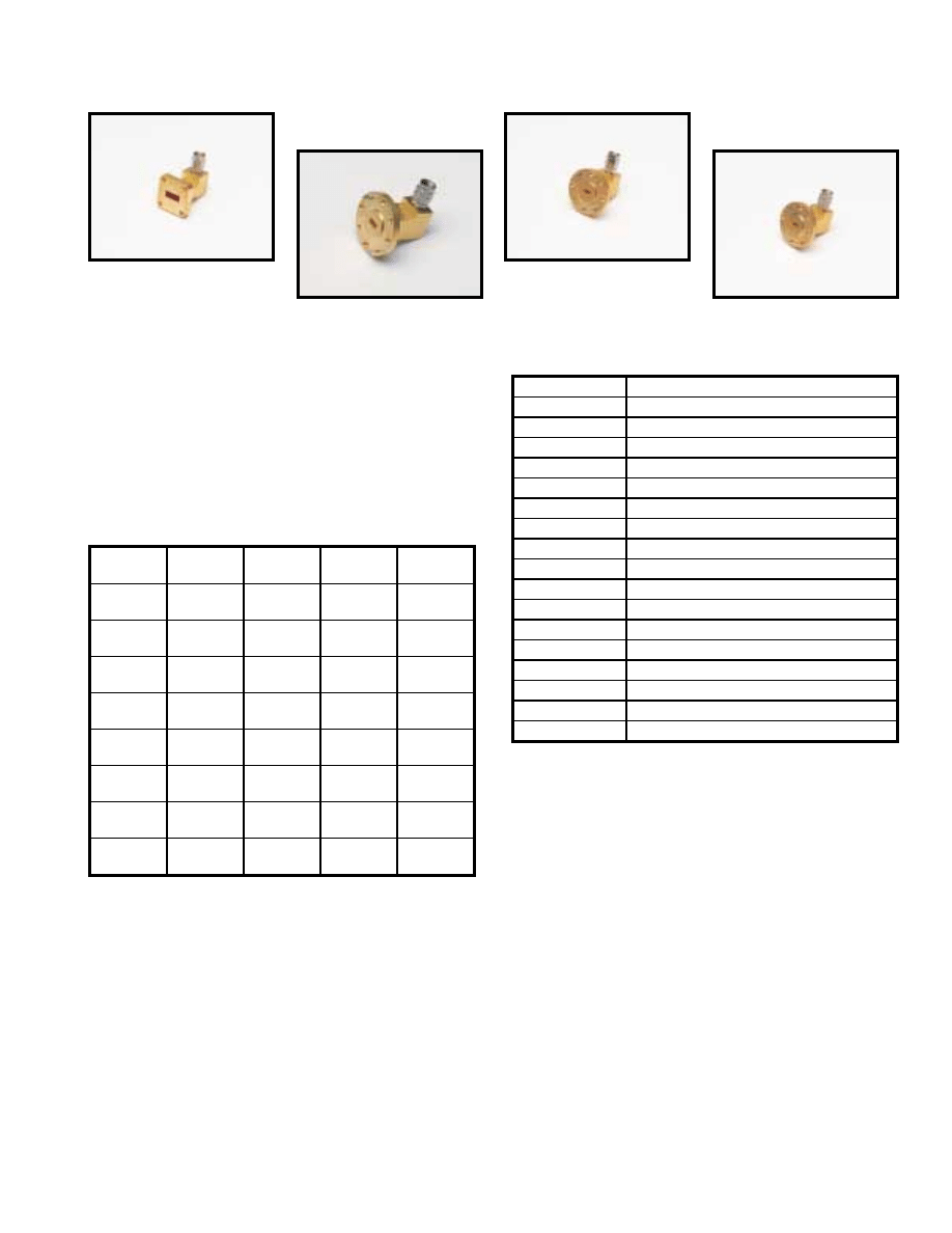
For further information about these products and more, contact us at 1-800-ANRITSU or visit www.us.anritsu.com
25
INSTRUMENTATION GRADE ADAPTERS
35WR Series 18 to 65 GHz
35WR42K
35WR19K
35WR22V
35WR19V
The 35 Series precision adapters transform standard or double-
ridge waveguide to coaxial K Connector® and V Connector®
interfaces, thus enabling convenient millimeter wave coaxial
measurements.
Features
• 18 to 65 GHz frequency coverage
• K Connector
®
compatibility with SMA and 3.5 mm
• V Connector
®
compatibility with 2.4 mm
• Standard and double-ridge designs
Specifications
Impedance: 50 ohms
Maximum input power: 1 Watt
Temperature range: –55°C to +125°C
Ordering information
Please specify model/order number, name, and quantity when ordering.
Model
Frequency
range (GHz)
Connectors
W/G flange
UG-(_) U
SWR
35WRD180K
35WRD180KF
18 to 40
WRD180 to K(m)
WRD180 to K(f)
N/A
1.25
35WR42K
35WR42KF
18 to 26.5
WR42 to K(m)
WR42 to K(f)
595
1.25
35WR28K
35WR28KF
26.5 to 40
WR28 to K(m)
WR28 to K(f)
599
1.25
35WR22K
35WR22KF
33 to 50
WR22 to K(m)
WR22 to K(f)
383
1.30
35WR22V
35WR22VF
33 to 50
WR22 to V(m)
WR22 to V(f)
383
1.30
35WR19K
35WR19KF
40 to 50
Usable to 54
WR19 to K(m)
WR19 to K(f)
383
1.30
35WR19V
35WR19VF
40 to 60
WR19 to K(m)
WR19 to K(f)
383
1.30
35WR15V
35WR15VF
50 to 65
WR15 to V(m)
WR15 to V(f)
385
1.30
Model/Order No.
Name
Precision waveguide to coax adapter
35WRD180K
18 to 40 GHz, WRD180 (double ridge waveguide) to K(m)
35WRD180KF
18 to 40 GHz, WRD180 (double ridge waveguide) to K(f)
35WR42K
18 to 26.5 GHz, WR42-K(m)
35WR42KF
18 to 26.5 GHz, WR42-K(f)
35WR28K
26.5 to 40 GHz, WR28-K(m)
35WR28KF
26.5 to 40 GHz, WR28-K(f)
35WR22K
33 to 50 GHz, WR22-K(m)
35WR22KF
33 to 50 GHz, WR22-K(f)
35WR22V
33 to 50 GHz, WR22-V(m)
35WR22VF
33 to 50 GHz, WR22-V(f)
35WR19K
40 to 50 GHz (usable to 54 GHz), WR19-K(m)
35WR19KF
40 to 50 GHz (usable to 54 GHz), WR19-K(f)
35WR19V
40 to 60 GHz, WR19-V(m)
35WR19VF
40 to 60 GHz, WR19-V(f)
35WR15V
50 to 65 GHz (usable to 67 GHz), WR15-V(m)
35WR15VF
50 to 65 GHz (usable to 67 GHz), WR15-V(f)
Outline drawings for the 35 Series Waveguide-to-Coaxial Adapters,
18 to 65 GHz, are shown on the following two pages.
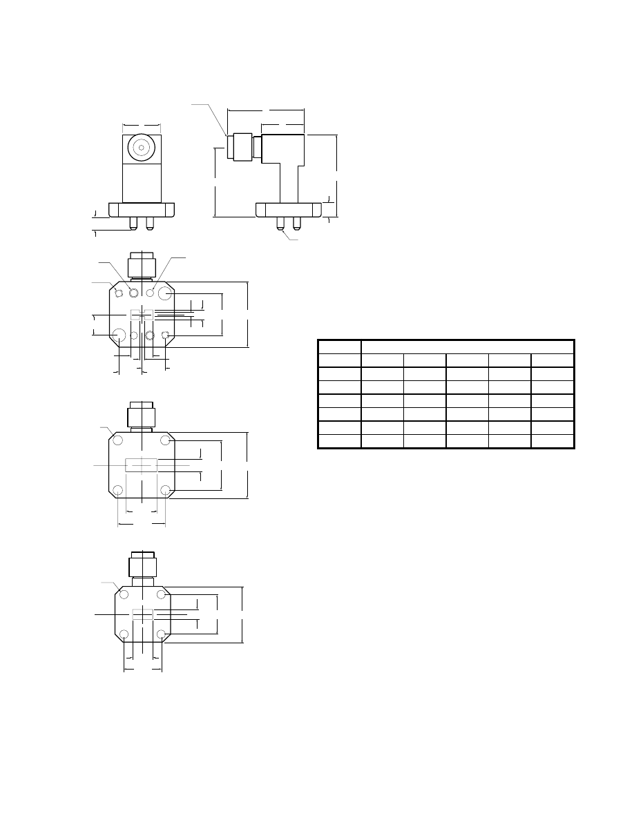
For further information about these products and more, contact us at 1-800-ANRITSU or visit www.us.anritsu.com
26
INSTRUMENTATION GRADE ADAPTERS
35WR Series 18 to 65 GHz
Outline Drawings
B
C
A
E
D
ALIGNMENT PIN
2 PLACES
(WR180 ONLY)
MALE OR FEMALE,
K CONNECTOR
4.37
4.77 TYPICAL
2.95 DIA. THRU
4 PLACES
35WR42K, 35WR42KF
4.31
17.0
22.23 SQ.
16.26
10.67
ALIGNMENT PIN
2 PLACES
2.44 DIA. THRU
2 PLACES
35WRD180K, 35WRD180KF
7.92
7.92
7.31
1.83
1.45
3.40
14.22
22.23 SQ.
7.11
4-40 UNC-2B
2 PLACES
35WR28K, 35WR28KF
2.95 DIA. THRU
4 PLACES
19.05 SQ.
13.46
3.56
7.11
12.7
Dimension in millimeters
35WRD180K, 35WRD180KF, 35WR42K, 35WR42KF, 35WR28K, 35WR28KF outlines
Model
Dimensions (mm)
A
B
C
D
E
35WRD180K8
13.20
27.9
14.43
28.40
23.80
35WRD180KF
13.20
22.9
14.43
28.40
23.80
35WR42K
13.20
27.9
14.43
28.14
23.93
35WR42KF
13.20
22.9
14.43
28.14
23.93
35WR28K
10.67
27.9
14.86
28.78
23.93
35WR28KF
10.67
22.9
14.86
28.78
23.88
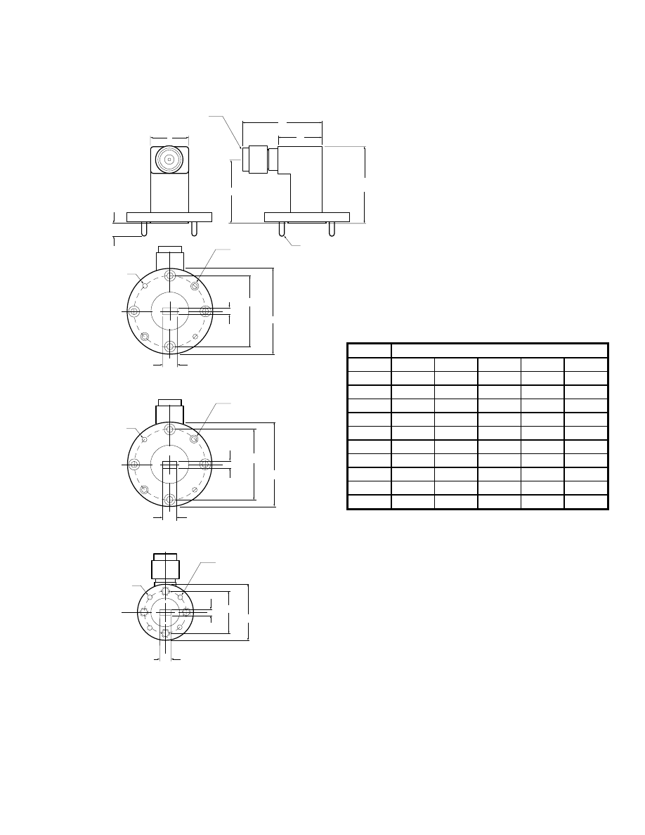
For further information about these products and more, contact us at 1-800-ANRITSU or visit www.us.anritsu.com
27
INSTRUMENTATION GRADE ADAPTERS
35WR Series 18 to 65 GHz
Outline Drawings
ALIGNMENT PIN
2 PLACES
2.46 DIA. THRU
2 PLACES
35WR22K, 35WR22KF,
35WR22V, 35WR22VF
28.57 DIA.
2.84
23.82 DIA.
5.69
2.46 DIA. THRU
2 PLACES
ALIGNMENT PIN
2 PLACES
35WR19K, 35WR19KF,
35WR19V, 35WR19VF
28.57 DIA.
23.82 DIA.
2.39
4.77
E
D
B
C
A
MALE OR FEMALE,
K OR V CONNECTOR
ALIGNMENT PIN
2 PLACES
3.96
ALIGNMENT PIN
2 PLACES
1.7 DIA. THRU
2 PLACES
35WR15V, 35WR15VF
19.05 DIA.
14.3 DIA.
1.88
3.76
Dimension in millimeters
35WR22K, 35WR22KF, 35WR22V, 35WR22VF, 35WR19K, 35WR19KF, 35WR19V, 35WR19VF, 35WR15V, and 35WR15VF outlines
Model
Dimensions (mm)
A
B
C
D
E
35WR22K
12.70
26.9
14.73
25.76
21.44
35WR22KF
12.70
21.6
14.73
25.76
21.44
35WR22V
12.70
26.9
14.73
25.76
21.44
35WR22VF
12.70
21.6
14.73
25.76
21.44
35WR19K
12.70
26.9
14.73
25.76
21.44
35WR19KF
12.70
21.6
14.73
25.76
21.44
35WR19V
12.70
27.9
14.73
25.76
21.44
35WR19VF
12.70
22.6
14.73
25.76
21.44
35WR15V
12.70
24.4
12.19
26.97
21.62
35WR15VF
12.70
20.3
12.19
26.97
21.62
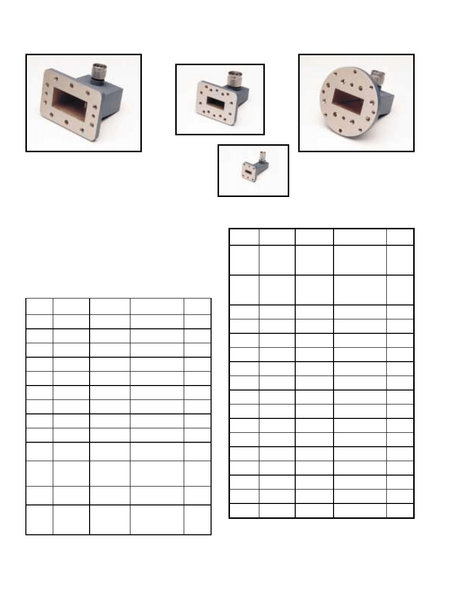
For further information about these products and more, contact us at 1-800-ANRITSU or visit www.us.anritsu.com
28
INSTRUMENTATION GRADE ADAPTERS
35U, 35C Series 3.3 to 26.5 GHz
35UM40N
35UM84N
35UA187N
The 35U and 35C Series precision adapters transform standard
waveguide to coaxial N and K Connector
®
interfaces, thus enabling
convenient microwave coaxial measurements.
Features
• 3.3 to 26.5 GHz frequency coverage
• N connector compatibility
• K Connector
®
compatibility with SMA and 3.5 mm
Specifications
35UA42K
Model
Frequency
range (GHz)
Connectors
W/G flange UG-(_) U
SWR
35UM40N
3.3 to 4.9
WR229 to N(m)
WG11A to N(m)
PDR40
1.08
35UM48N
3.9 to 5.8
WR187 to N(m)
WG12 to N(m)
CAR48, PAR48,
UAR48, PDR48
1.08
35UM58N
4.9 to 7.0
WR159 to N(m)
WG13 to N(m)
CAR58, PAR58,
UAR58, PDR58
1.08
35UM70N
5.8 to 8.2
WR137 to N(m)
WG14 to N(m)
CAR70, PAR70,
UAR70, PDR70
1.08
35UM84N
7.0 to 10
WR112 to N(m)
WG15 to N(m)
CBR84, UBR84,
PBR84, PDR84
1.08
35UM100N
8.2 to 12.4
WR90 to N(m)
WG16 to N(m)
CBR100, UBR100,
PBR100, PDR100
1.08
35UM120N
10 to 15
WR75 to N(m)
WG17 to N(m)
CBR120, UBR120,
PBR120, PDR120
1.08
35UM140N
12.4 to 18
WR62 to N(m)
WG18 to N(m)
CBR140, UBR140,
PBR140, PDR140
1.08
35UM220K
17 to 26.5
WR42 to K(m)
WG20 to K(m)
CBR220, UBR220,
PBR220, PDR220
1.20
35UA229N
3.3 to 4.9
WR229 to N(m)
WG11A to N(m)
CPR229F, CPR229G,
UG-1350/U, UG-1351/U,
UG-1726/U, UG-1727/U
1.08
35UA187N
3.9 to 5.8
WR187 to N(m)
WG12 to N(m)
CPR187F, CPR187G,
UG-1352/U, UG-1353/U,
UG-1728/U, UG-1729/U,
UG-148/U, UG-149A/U
1.08
35UA159N
4.9 to 7.0
WR159 to N(m)
WG13 to N(m)
CPR159F, CPR159G,
UG-1354/U, UG-1355/U,
UG-1730/U, UG-1731/U
1.08
35UA137N
5.8 to 8.2
WR137 to N(m)
WG14 to N(m)
CPR137F, CPR137G,
UG-1356/U, UG-1357/U,
UG-1732/U, UG-1733/U,
UG-343B/U, UG-344/U,
UG-440B/U, UG-441/U
1.08
Model
Frequency
range (GHz)
Connectors
W/G flange UG-(_) U
SWR
35UA112N
7.0 to 10
WR112 to N(m)
WG15 to N(m)
CPR112F, CPR112G,
UG-1358/U, UG-1359/U,
UG-1734/U, UG-1735/U,
UG-52B/U, UG-51/U,
UG-137B/U, UG-138/U
1.08
35UA90N
8.2 to 12.4
WR90 to N(m)
WG16 to N(m)
CPR90F, CPR90G,
UG-1360/U, UG-1361/U,
UG-1736/U, UG-1737/U,
UG-40B/U, UG-39/U,
UG-135B/U, UG-136/U
1.08
35UA75N
10 to 15
WR75 to N(m)
WG17 to N(m)
WR75
1.08
35UA62N
12.4 to 18
WR62 to N(m)
WG18 to N(m)
UG-541A/U, UG-419A/U
UG-1665/U, UG-1666/U
1.08
35UA42K
17 to 26.5
WR42 to K(m)
WG20 to K(m)
UG-596A/U, UG-595/U,
UG-597/U, UG-598A/U
1.08
35CMR229N
3.3 to 4.9
WR229 to N(m)
CMR229
1.08
35CMR187N
3.9 to 5.8
WR187 to N(m)
WG12 to N(m)
CMR187, UG-1475/U,
UG-148/U
1.08
35CMR159N
4.9 to 7.0
WR159 to N(m)
WG13 to N(m)
CMR159
1.08
35CMR137N
5.8 to 8.2
WR137 to N(m)
WG14 to N(m)
CMR137, UG-1476/U
1UG-1481/U
1.08
35CMR112N
7.0 to 10
WR112 to N(m)
WG15 to N(m)
CMR112, UG-1477/U
UG-1482/U
1.08
35CMR90N
8.2 to 12.4
WR90 to N(m)
WG16 to N(m)
CMR90, UG-1478/U
UG-1483/U
1.08
35UER40N
3.3 to 4.9
WR229 to N(m)
WG11A to N(m)
UER40
1.08
35UER48N
3.9 to 5.8
WR187 to N(m)
WG12 to N(m)
UER48
1.08
35UER58N
4.9 to 7.0
WR159 to N(m)
WG13 to N(m)
UER58
1.08
35UER70N
5.8 to 8.2
WR137 to N(m)
WG14 to N(m)
UER70
1.08
35UER84N
7 to 10
WR112 to N(m)
WG15 to N(m)
UER84
1.08
35UER100N
8.2 to 12.4
WR90 to N(m)
WG16 to N(m)
UER100
1.08
Specifications
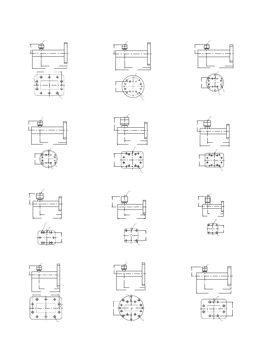
For further information about these products and more, contact us at 1-800-ANRITSU or visit www.us.anritsu.com
29
INSTRUMENTATION GRADE ADAPTERS
35U, 35C Series 3.3 to 26.5 GHz
M6
4 PLACES
35UM40N
82.30
±
0.05
4.76 DIA.
2 PLACES
+0.01
–0.00
Dimensions in millimeters
CONNECTOR
43.7
55.88
±
0.76
76.2
±
0.76
35UM40N outline
M5
2 PLACES
M5
4 PLACES
36.52
±
0.05
35UM70N
CONNECTOR
34.5
50.8
±
0.76
67.31
±
0.76
Dimensions in millimeters
3.19 DIA. +0.01
2 PLACES –0.00
35UM70N outline
M4
4 PLACES
28.50
±
0.05
35UM120N
CONNECTOR
30.5
43.18
±
0.76
55.88
±
0.76
3.19 DIA.
2 PLACES
+0.01
–0.00
Dimensions in millimeters
35UM120N outline
35UA229N
82.29
±
0.05
#1/4-20
4 PLACES
43.7
55.88
±
0.76
76.2
±
0.76
Dimensions in millimeters
CONNECTOR
4.76 DIA. +0.01
2 PLACES
−
0.00
35UA229N outline
M5
4 PLACES
M6
4 PLACES
46.43
±
0.05
35UM48N
4.76 DIA.
2 PLACES
+0.01
–0.00
Dimensions in millimeters
CONNECTOR
39.6
59.69
±
0.76
76.2
±
0.76
35UM48N outline
M4
6 PLACES
37.43
±
0.05
35UM84N
CONNECTOR
32.0
45.72
±
0.76
63.5
±
0.76
Dimensions in millimeters
3.19 DIA. +0.01
2 PLACES –0.00
35UM84N outline
M4
2 PLACES
24.28
±
0.05
35UM140N
CONNECTOR
29.7
43.18
±
0.76
55.88
±
0.76
3.19 DIA.
2 PLACES
+0.01
–0.00
Dimensions in millimeters
35UM140N outline
#1/4-20
8 PLACES
35UA187N
50.8
±
0.05
Dimensions in millimeters
4.76 DIA.
2 PLACES
+0.01
–0.00
39.6
59.69
±
0.76
76.2
±
0.76
CONNECTOR
35UA187N outline
M5
2 PLACES
M6
4 PLACES
69.85
±
0.05
35UM58N
CONNECTOR
36.8
57.15
±
0.76
71.12
±
0.76
4.76 DIA.
2 PLACES
+0.01
–0.00
Dimensions in millimeters
35UM58N outline
M4
6 PLACES
32.5
±
0.05
35UM100N
CONNECTOR
30.7
43.18
±
0.76
55.88
±
0.76
Dimensions in millimeters
3.19 DIA. +0.01
2 PLACES –0.00
35UM100N outline
M3
2 PLACES
17.01
±
0.05
35UM220K
CONNECTOR
19.8
30.48
±
0.76
38.1
±
0.76
2.37 DIA.
2 PLACES
+0.01
–0.00
Dimensions in millimeters
35UM220K outline
57.15
±
0.76
71.12
±
0.76
44.45
±
0.05
36.8
Dimensions in millimeters
#1/4-20
4 PLACES
35UA159N
CONNECTOR
4.76 DIA. +0.01
2 PLACES
−
0.00
35UA159N outline
Outline Drawings
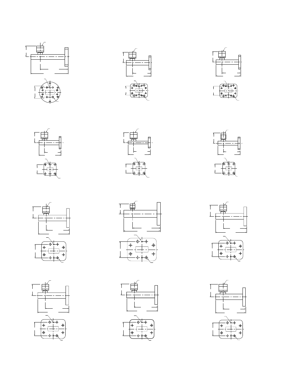
For further information about these products and more, contact us at 1-800-ANRITSU or visit www.us.anritsu.com
30
INSTRUMENTATION GRADE ADAPTERS
35U, 35C Series 3.3 to 26.5 GHz
CONNECTOR
34.5
50.8
±
0.76
67.31
±
0.76
Dimensions in millimeters
#10-32
6 PLACES
35UA137N
36.52
±
0.05
4.76 DIA. +0.01
2 PLACES
−
0.00
35UA137N outline
28.50
±
0.05
#6-32
2 PLACES
35UA75N
43.18
±
0.76
55.88
±
0.76
CONNECTOR
30.5
Dimensions in millimeters
3.19 DIA. +0.01
2 PLACES
−
0.00
35UA75N outline
#6-32
4 PLACES
42.87
±
0.05
35CMR229N
43.7
55.88
±
0.76
76.2
±
0.76
Dimensions in millimeters
CONNECTOR
4.76 DIA. +0.01
2 PLACES
−
0.00
35CMR229N outline
#6-32
4 PLACES
CONNECTOR
29.97
±
0.05
35CMR137N
34.5
50.8
±
0.76
67.31
±
0.76
Dimensions in millimeters
3.19 DIA. +0.01
2 PLACES
−
0.00
35CMR137N outline
CONNECTOR
45.72
±
0.76
32.0
Dimensions in millimeters
37.44
±
0.05
#8-32
6 PLACES
35UA112N
63.5
±
0.76
3.19 DIA. +0.01
2 PLACES
−
0.00
35UA112N outline
CONNECTOR
29.7
43.18
±
0.76
55.88
±
0.76
#6-32
2 PLACES
24.28
±
0.05
35UA62N
Dimensions in millimeters
3.19 DIA. +0.01
2 PLACES
−
0.00
35UA62N outline
#6-32
4 PLACES
CONNECTOR
36.32
±
0.05
35CMR187N
39.6
59.69
±
0.76
76.2
±
0.76
Dimensions in millimeters
4.76 DIA. +0.01
2 PLACES
−
0.00
35CMR187N outline
#6-32
4 PLACES
CONNECTOR
26.26
±
0.05
35CMR112N
32.0
45.72
±
0.76
63.5
±
0.76
Dimensions in millimeters
3.19 DIA. +0.01
2 PLACES
−
0.00
35CMR112N outline
CONNECTOR
43.18
±
0.76
55.88
±
0.76
Dimensions in millimeters
#8-32
6 PLACES
32.51
±
0.05
35UA90N
30.7
3.19 DIA. +0.01
2 PLACES
−
0.00
35UA90N outline
CONNECTOR
19.8
30.48
±
0.76
38.1
±
0.76
Dimensions in millimeters
#4-40
2 PLACES
17.01
±
0.05
35UA42K
2.37 DIA. +0.00
2 PLACES
−
0.00
35UA42K outline
#6-32
4 PLACES
CONNECTOR
33.68
±
0.05
35CMR159N
36.8
57.15
±
0.76
71.12
±
0.76
Dimensions in millimeters
4.76 DIA. +0.01
2 PLACES
−
0.00
35CMR159N outline
#6-32
4 PLACES
CONNECTOR
23.11
±
0.05
35CMR90N
30.7
43.18
±
0.76
55.88
±
0.76
Dimensions in millimeters
3.19 DIA. +0.01
2 PLACES
−
0.00
35CMR90N outline
Outline Drawings
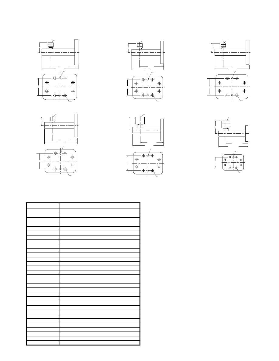
For further information about these products and more, contact us at 1-800-ANRITSU or visit www.us.anritsu.com
31
INSTRUMENTATION GRADE ADAPTERS
35U, 35C Series 3.3 to 26.5 GHz
Outline Drawings
M4 DIA.
8 PLACES
42.87
±
0.05
35UER40N
43.7
55.88
±
0.76
76.2
±
0.76
Dimensions in millimeters
CONNECTOR
4.76 DIA. +0.01
2 PLACES
−
0.00
35UER40N outline
M4 DIA.
8 PLACES
29.97
±
0.05
35UER70N
50.8
±
0.76
67.31
±
0.76
Dimensions in millimeters
CONNECTOR
34.5
3.19 DIA. +0.01
2 PLACES –0.00
35UER70N outline
36.32
±
0.05
35UER48N
39.6
59.69
±
0.76
Dimensions in millimeters
CONNECTOR
76.2
±
0.76
M4 DIA.
8 PLACES
4.76 DIA . +0.01
2 PLACES
−
0.00
35UER48N outline
26.26
±
0.05
35UER84N
45.72
±
0.76
Dimensions in millimeters
M4
6 PLACES
32.0
CONNECTOR
63.5
±
0.76
3.19 DIA. +0.01
2 PLACES –0.00
35UER84N outline
M4 DIA.
8 PLACES
33.68
±
.0.05
35UER58N
71.12
±
0.76
Dimensions in millimeters
57.15
±
0.76
36.8
CONNECTOR
4.76 DIA. +0.01
2 PLACES –0.00
35UER58N outline
M4 DIA.
8 PLACES
23.11
±
0.05
35UER100N
CONNECTOR
30.7
43.18
±
0.76
55.88
±
0.76
Dimensions in millimeters
3.19 DIA. +0.01
2 PLACES
−
0.00
35UER100N outline
Ordering information
Please specify model/order number, name, and quantity when ordering.
Model/Order No.
Name
Coaxial adapter
35UM40N
N(m), metric, 3.30 to 4.90 GHz
35UM48N
N(m), metric, 3.95 to 5.85 GHz
35UM58N
N(m), metric, 4.90 to 7.05 GHz
35UM70N
N(m), metric, 5.85 to 8.20 GHz
35UM84N
N(m), metric, 7.05 to 10.00 GHz
35UM100N
N(m), metric, 8.20 to 12.40 GHz
35UM120N
N(m), metric, 10.00 to 15.00 GHz
35UM140N
N(m), metric, 12.40 to 18.0 GHz
35UM220K
K(m), metric, 17.00 to 26.5 GHz
35UA229N
N(m), US, 3.30 to 4.90 GHz
35UA187N
N(m), US, 3.95 to 5.85 GHz
35UA159N
N(m), US, 4.90 to 7.05 GHz
35UA137N
N(m), US, 5.85 to 8.20 GHz
35UA112N
N(m), US, 7.05 to 10.00 GHz
35UA90N
N(m), US, 8.20 to 12.40 GHz
35UA75N
N(m), US, 10.00 to 15.00 GHz
35UA62N
N(m), US, 12.40 to 18.0 GHz
35UA42K
K(m), US, 17.00 to 26.5 GHz
35CMR229N
N(m), CMR, 3.30 to 4.90 GHz
35CMR187N
N(m), CMR, 3.95 to 5.85 GHz
35CMR159N
N(m), CMR, 4.90 to 7.05 GHz
35CMR137N
N(m), CMR, 5.85 to 8.20 GHz
35CMR112N
N(m), CMR, 7.05 to 10.00 GHz
35CMR90N
N(m), CMR, 8.20 to 12.40 GHz
35UER40N
N(m), UER, 3.30 to 4.90 GHz
35UER48N
N(m), UER, 3.95 to 5.85 GHz
35UER58N
N(m), UER, 4.90 to 7.05 GHz
35UER70N
N(m), UER, 5.85 to 8.20 GHz
35UER84N
N(m), UER, 7.05 to 10.00 GHz
35UER100N
N(m), UER, 8.20 to 12.40 GHz
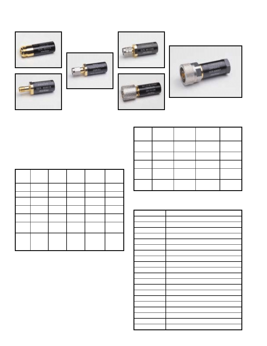
For further information about these products and more, contact us at 1-800-ANRITSU or visit www.us.anritsu.com
32
COAXIAL TERMINATIONS
26, 28, 29 Series DC to 67 GHz
26NF75
28KF50
28N50-2
28V50B
28K50
29A50-20
These precision, metrology-grade terminations are used in
measurement systems that need to achieve the smallest possible
reflections. Their excellent match makes them ideal as a reference
for fault location measurements on scalar network analyzers.
Precision termination features
• Accurate reference for SWR measurements
• Precise termination for test instrument ordevice under test
Precision termination specifications
Maximum Input Power: 0.5 W
When used with Anritsu airlines, the 29 Series Offset Terminations
permit measurements down to 1.006 SWR to 18 GHz, 1.01 SWR
to 26.5 GHz, and 1.02 SWR to 40 GHz.
Offset termination features
• 50
Ω
Offset Terminations for precise measurement
of low SWR or high directivity
• Measurements down to 1.006 SWR to 18 GHz,
1.01 SWR to 26.5 GHz, and 1.02 SWR to 40 GHz
Ordering information
Please specify model/order number, name, and quantity when ordering.
Offset termination specifications
Temperature range: +25°C ±5°C
Model
Frequency
range
(GHz)
Test port
connector
Input
impedance
(Ohms)
SWR
(F in GHz)
Dimensions
L(cm) x
dia(cm)
26N75A
26NF75A
DC to 3
N(m)
N(f)
75
1.013 Max.
5.2 x 2.2
4.8 x 1.6
28A50-1
DC to 18
GPC-7
50
1.02 Max.
5.2 x 2.2
28N50-2
28NF50-2
DC to 18
N(m)
N(f)
50
1.02 Max.
5.2 x 2.2
4.8 x 1.6
28N50-3
28NF50-3
DC to 8
N(m)
N(f)
50
1.03 Max.
5.2 x 2.2
4.8 x 1.6
28S50-1
28SF50-1
DC to 26.5
WSMA(m)
WSMA(f)
50
1.020 to 18.5 GHz
1.153 to 26.5 GHz
3.7 x 1.2
3.7 x 1.2
28K50
28KF50
DC to 40
K(m)
K(f)
50
1.040 to 18.5 GHz
1.070 to 26.5 GHz
1.135 to 40 GHz
3.7 x 1.2
3.7 x 1.2
28V50B
28VF50B
DC to 67
V(m)
V(f)
50
1.018 to 6 GHz
1.058 to 26.5 GHz
1.074 to 40 GHz
1.12 to 60 GHz
1.25 to 67 GHz
3.7 x 1.2
3.7 x 1.2
Model
Frequency
range
(GHz)
Test port
connector
Return loss
(dB)
Dimensions
L(cm) x
dia(cm)
29A50-20
DC to 18
GPC-7
20 ±0.5 to 1 GHz
20 ±1.0 to 4 GHz
20 ±1.5 to 18 GHz
5.2 x 2.2
29S50-20
DC to 26.5
WSMA(m)
20 ±1.5 to 18.5 GHz
20 ±2.5 to 26.5 GHz
3.7 x 1.2
29SF50-20
DC to 26.5
WSMA(f)
20 ±1.5 to 18.5 GHz
20 ±2.5 to 26.5 GHz
3.7 x 1.2
29K50-15
DC to 40
K(m)
15 ±1.5 to 18.5 GHz
15 ±2.5 to 26.5 GHz
15 ±3.5 to 40 GHz
3.7 x 1.2
29KF50-15
DC to 40
K(f)
15 ±1.5 to 18.5 GHz
15 ±2.5 to 26.5 GHz
15 ±3.5 to 40 GHz
3.7 x 1.2
Model/Order No.
Name
Precision termination
26N75A
DC to 3 GHz, 75
Ω
, N(m)
26NF75A
DC to 3 GHz, 75
Ω
, N(f)
28A50-1
DC to 18 GHz, 50
Ω
, GPC-7, Max. SWR=1.02
28N50-2
DC to 18 GHz, 40 dB, 50
Ω
, N(m)
28NF50-2
DC to 18 GHz, 40 dB, 50
Ω
, N(f)
28N50-3
DC to 8.6 GHz, 50
Ω
, N(m)
28NF50-3
DC to 8.6 GHz, 50
Ω
, N(f)
28S50-1
DC to 26.5 GHz, 50
Ω
, WSMA(m) (selected for higher accuracy)
28SF50-1
DC to 26.5 GHz, 50
Ω
, WSMA(f) (selected for higher accuracy)
28K50
DC to 40 GHz, 50
Ω
, K(m)
28KF50
DC to 40 GHz, 50
Ω
, K(f)
28V50B
DC to 65 GHz, V(m)
28VF50B
DC to 65 GHz, V(f)
Offset termination
29A50-20
DC to 18 GHz, 50
Ω
, GPC-7, 20 dB return loss
29S50-20
DC to 26.5 GHz, 50
Ω
, WSMA(m), 20 dB return loss
29SF50-20
DC to 26.5 GHz, 50
Ω
, WSMA(f), 20 dB return loss
29K50-15
DC to 40 GHz, 50
Ω
, K(m), 15 dB return loss
29KF50-15
DC to 40 GHz, 50
Ω
, K(f), 15 dB return loss
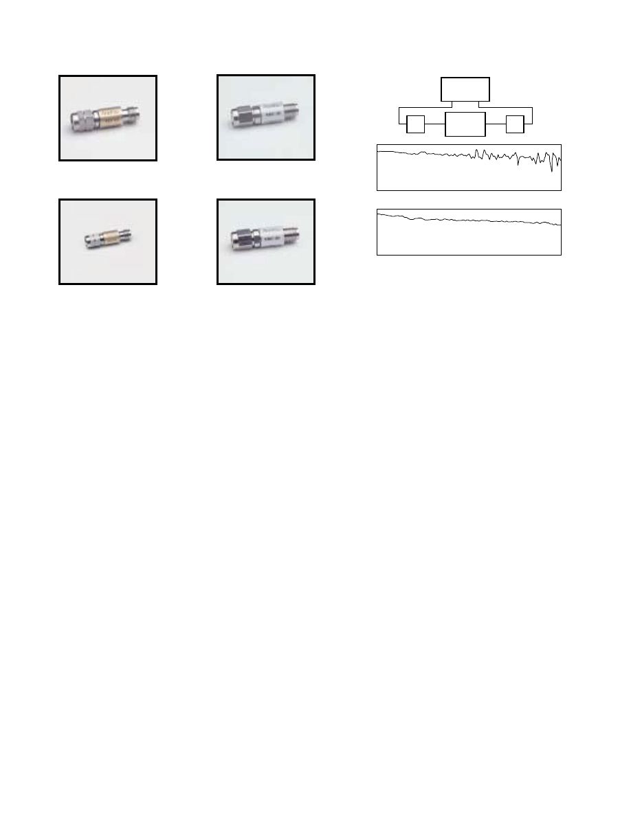
Frequency (GHz)
0
0.5
1.0
1.5
0
0.5
1.0
1.5
DC
8
12
18
26
40
Frequency (GHz)
DC
8
12
18
26
40
Without pads
With pads
Inser
tion loss
(dB)
Inser
tion loss
(dB)
Air line
under test
6 dB
Pad
6 dB
Pad
Lightning VNA
37269C
Port 1
Port 2
For further information about these products and more, contact us at 1-800-ANRITSU or visit www.us.anritsu.com
33
FIXED ATTENUATORS
41, 43 Series DC to 60 Series
Anritsu offers two series of fixed attenuators:
• The Gold Line (Series 41) for precision measurement
applications covering DC to 60 GHz
• The Silver Line (Series 43) for use in systems and OEM
equipment covering DC to 40 GHz
Both series offer fixed attenuation values of 3, 6, 10, or 20 dB
with models that span frequency range of DC to 26.5 GHz, 40 GHz,
or 60 GHz
Features
• 3, 6, 10, or 20 dB Attenuation up to 60 GHz
• Low SWR, 1.28 Up to 40 GHz
• SMA, 3.5 mm, and 2.4 mm compatibility
• Rugged and reliable K Connector
®
and V Connector
®
Advanced performance and reliability
Anritsu attenuators define the standard for fixed attenuator
performance and reliability. Performance, however, is not their only
distinguishing feature. Attenuators that use the K Connector
®
offer a
vast improvement in reliability, compared to attenuators with SMA
connectors. Attenuators that use the V Connector® can be connected
directly to 2.4 mm devices.
For applications in metrology and calibration laboratories where
precise characterization is essential, the Gold Line models are
available in sets consisting of 3, 6, 10, and 20 dB units. Each is
provided with attenuation and SWR calibration data. Calibration
data is also optionally available for individual units, each of which is
serialized.
The reliability of the attenuator connectors is affected by insertion
force, outer conductor mating area, and mating alignment. The
K Connector
®
is used because it has excellent performance in all
of these areas. For example, a typical female SMA, 3.5 mm center
conductor requires up to 27N* of insertion force compared to
2.2N* for the K Connector
®
. In addition, the K Connector
®
outer
conductor is four times thicker than SMA, resulting in a
conservative order-of-magnitude improvement in the number of
reliable connections.
To avoid a major cause of connector failure, the K Connector
®
male pin is deliberately made shorter than the SMA pin. Therefore,
the outer housing is properly aligned prior to center conductor
mating, preventing destructive alignment.
Gold Line - improved measurement accuracy
Adding Gold Line attenuators to your attenuation measurement
setup will improve your measurement accuracy. In the test setup
shown, the insertion loss of an air line was measured, first without
and then with matching 6 dB pads. The difference in the accuracy
of the two measurements is striking. By attenuating reflections and
re-reflections that occur at the input and output of the air line, the
pads reduce mismatch errors and allow the system to measure more
accurately the actual insertion loss.
Silver Line - improved system reliability
Fixed attenuators used in systems or OEM equipment must be small,
lightweight, economical, and reliable under severe environmental
conditions. The Silver Line meets these requirements. K Connectors
ensure well-seated, low-reflection connections that provide
consistent operation year after year.
The Series 43 (Silver Line) attenuator’s small size, 8 mm dia. x 28.8 mm
length, and light weight, 8g make them an attractive choice for
miniaturized, lightweight systems.
* Force is measured in Newtons (N).
Improved Measured Accuracy
41V-10
43KC-10
41V-20
43KC-20
For further information about these products and more, contact us at 1-800-ANRITSU or visit www.us.anritsu.com
34
FIXED ATTENUATORS
41, 43 Series DC to 60 Series
1. For traceability, all Gold Line attenuators are serialized.
2. ±1 dB from DC to 26.5 GHz; ±1.3 dB from >26.5 to 40 GHz, including frequency response and DC offset.
Ordering information
Please specify model/order number, name, and quantity when ordering.
Single fixed attenuators may be ordered from the table above.
* A set of 3, 6, 10, and 20 dB Gold line (Series 41).Attenuators are supplied in a
handsome hardwood case. Calibration data are included for each unit.
** Attenuation and SWR test data are provided for input and output ports at
500 MHz frequency intervals.
Common specifications
Specifications
Impedance
50 Ohms
Power rating (average)
2W at 20°C; 1W at 85°C
Temperature coefficient
0.001 dB/dB/°C
Connectors
V Connector
®
Male and female compatible with 2.4 mm
K Connector
®
Male and female, compatible with SMA and 3.5 mm
Material
Passivated stainless steel housing
Size
Length
28.8 mm ±0.5 mm
Diameter
8 mm
Weight
8g
Temperature range
Operating
–55°C to +85°C
Nonoperating
–55°C to +125°C
Model/Order No.
Name
Precision Fixed Attenuator
41KB-3, 6, 10, or 20
3 dB, DC to 26.5 GHz, 50
Ω
, K(m)-K(f)
41KC-3, 6, 10, or 20
3 dB, DC to 40 GHz, 50
Ω
, K(m)-K(f)
41V-3, 6, 10, or 20
3 dB, DC to 60 GHz, 50
Ω
, V(m)-V(f)
Precision Fixed Attenuator Set
41KB-S*
41KB Series
41KC-S*
41KC Series
41V-S*
41V Series
Fixed Attenuator
43KB-3, 6, 10, or 20
3 dB, DC to 26.5 GHz, 50
Ω
, K(m)-K(f)
43KC-3, 6, 10, or 20
3 dB, DC to 40 GHz, 50
Ω
, K(m)-K(f)
Option
Option C**
Calibration Data
Gold Line
Model
1
Attenuation
(dB)
Attenuation Accuracy
SWR
DC-18 GHz
18-26.5 GHz
26.5-40 GHz
40-60 GHz
DC-12 GHz
12-18 GHz
18-26.5 GHz
26.5-40 GHz
40-60 GHz
DC to 60 GHz
41V-3
41V-6
41V-10
41V-20
3
6
10
20
±0.5
±0.5
±0.5
±0.5
±0.6
±0.6
±0.6
±0.6
±0.9
±0.9
±0.9
±0.9
±1.20
±1.20
±1.20
±1.20
1.15
1.15
1.15
1.15
1.20
1.20
1.20
1.20
1.30
1.25
1.25
1.25
1.50
1.40
1.40
1.40
1.90
1.70
1.70
1.70
DC to 40 GHz
41KC-3
41KC-6
41KC-10
41KC-20
3
6
10
20
±0.4
±0.4
±0.4
±0.4
±0.5
±0.5
±0.5
±0.5
±0.8
±0.8
±0.8
±0.8
-
-
-
-
1.10
1.10
1.10
1.10
1.15
1.15
1.15
1.15
1.23
1.18
1.18
1.18
1.42
1.28
1.28
1.28
-
-
-
-
DC to 26.5 GHz
41KB-3
41KB-6
41KB-10
41KB-20
3
6
10
20
±0.4
±0.4
±0.4
±0.4
±0.5
±0.5
±0.5
±0.5
-
-
-
-
-
-
-
-
1.10
1.10
1.10
1.10
1.15
1.15
1.15
1.15
1.23
1.18
1.18
1.18
-
-
-
-
-
-
-
-
Silver Line
Model
Attenuation
2
(dB)
Attenuation Accuracy
SWR
DC-18 GHz
18-26.5 GHz
26.5-40 GHz
40-60 GHz
DC-12 GHz
12-18 GHz
18-26.5 GHz
26.5-40 GHz
40-60 GHz
DC to 40 GHz
43KC-3
43KC-6
43KC-10
43KC-20
3
6
10
20
±0.5
±0.5
±0.5
±0.5
±0.6
±0.6
±0.6
±0.6
±0.9
±0.9
±0.9
±0.9
-
-
-
-
1.15
1.15
1.15
1.15
1.20
1.20
1.20
1.20
1.30
1.30
1.30
1.30
1.50
1.40
1.40
1.40
-
-
-
-
DC to 26.5 GHz
43KB-3
43KB-6
43KB-10
43KB-20
3
6
10
20
±0.5
±0.5
±0.5
±0.5
±0.6
±0.6
±0.6
±0.6
-
-
-
-
-
-
-
-
1.15
1.15
1.15
1.15
1.20
1.20
1.20
1.20
1.30
1.30
1.30
1.30
-
-
-
-
-
-
-
-
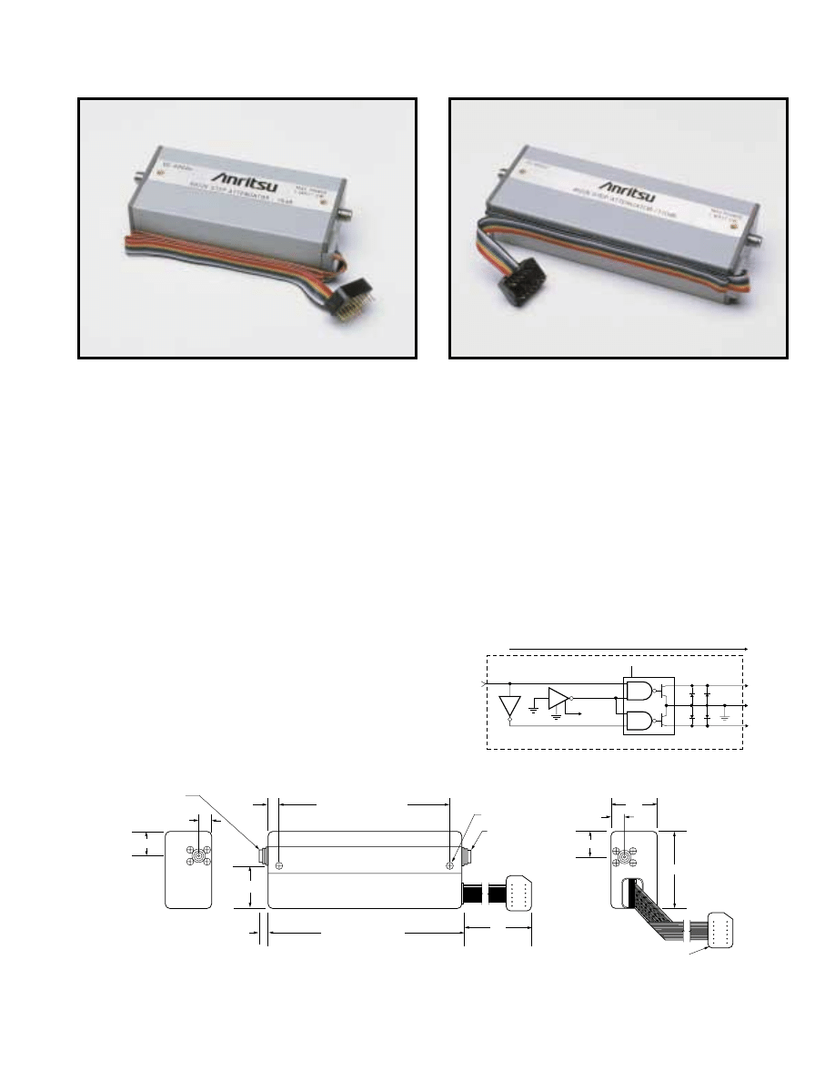
For further information about these products and more, contact us at 1-800-ANRITSU or visit www.us.anritsu.com
35
STEP ATTENUATORS
4400, 4500, 4600 Series DC to 40 GHz
Anritsu programmable step attenuators bring a substantial increase
in the frequency and attenuation range available in one small
package. Using the latest technology, these units offer superior
performance, reliability, and ease of use to 40 GHz. All are plug-
compatible with competitive units.
Features
• DC-20 GHz, DC-26.5 GHz, DC-40 GHz
• 70 dB and 110 dB attenuation ranges
• Lowest insertion loss
• Precise repeatability
• Life of 5 million operations
• Small, rugged, light weight
Advanced technology-advanced
performance
Anritsu has lowered throughline loss by designing the first 40 dB
attenuator sections to operate above 18 GHz. Compared with
designs that use 30 dB sections, these attenuators have a shorter thru
path and fewer switching contacts. As a result, insertion loss is as
much as 1.7 dB less than that of units made by other companies. RF
input power requirements for systems that use these attenuators can
be reduced, saving money, space, and weight.
Integrated switching structure
The push rods that switch in the attenuator modules and thrulines are
driven by a solenoid actuator. By designing the solenoid as an
integral part of the attenuator assembly, switching speeds of 20 ms
(including settling time) are achieved. Upon completion of the
switching operation, the solenoid is magnetically latched to
withstand severe shock and vibration. At the same time, the solenoid
current is automatically turned off to save power and to minimize
temperature rise.
Also integrated in the design is solid state dc switching circuitry that
avoids the relatively high failure rate of mechanical DC switches.
Each attenuator section is controlled by its own driver circuit, which
requires 24V, 125 mA. A typical external driver circuit for one
section is shown in the figure below.
102.9 4422K, 4522K, 4622K
90.2 4412K, 4512K, 4612K
7.1
17.8
7.1
17.8
24.4
44.5
14 Pin Dip
XXXX K STEP ATTENUATOR
SN XXXXX
MAX POWER
1 WATT CW
117 4422K, 4522K, 4622K
76.2 4412K, 4512K, 4612K
Female
Connector
Female
Connector
5.7
2 Places
7.0
25.4
4-40 UNC-2B
410
Dimensions in millimeters
4400, 4500, and 4600 series outline
4622K
4612K
+5 V
+5 V
8
3
4
5
Control
Line
Control
Line
1N4446
75451
1
2
6
6
7
14
7
9
10
11
TTL
Input
75LS04
75LS04
Power
+24 V
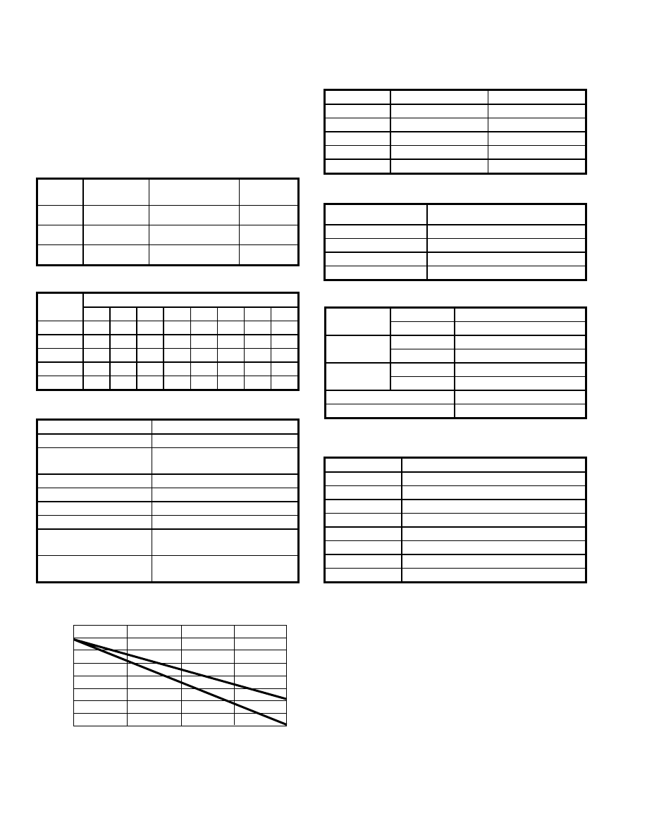
For further information about these products and more, contact us at 1-800-ANRITSU or visit www.us.anritsu.com
36
STEP ATTENUATORS
4400, 4500, 4600 Series DC to 40 GHz
Accuracy enhancing calibration data
Attenuation accuracy can be improved by using optional calibration
data taken on an Anritsu vector network analyzer. The calibration
data can be used to normalize the effect of frequency response and
reflections. The calibration data is traceable to NIST.
Specifications
Frequency and attenuation ranges
Insertion loss (maximum)
Attenuator accuracy (± dB)
Impedance match
Mechanical
Electrical
Ordering information
Please specify model/order number, name, and quantity when ordering.
0
0
0.5
1.0
4.0
40
Frequency (GHz)
Inser
tion loss (dB)
4412K, 4512K, 4612K
4422K, 4522K, 4622K
3.5
3.0
2.5
2.0
1.5
10
20
30
*Calibration data is taken every 100 MHz from DC to 900 MHz and every 500 MHz
from 1 GHz to 40 GHz.
Environment
Model
Frequency range
Attenuation range
in 10 dB steps
Connectors
4412K
4422K
DC to 20 GHz
0 to 70 dB
0 to 110 dB
K(f)
4512K
4522K
DC to 26.5 GHz
0 to 70 dB
0 to 110 dB
K(f)
4612K
4622K
DC to 40 GHz
0 to 70 dB
0 to 110 dB
K(f)
Frequency
(GHz)
Attenuation (dB)
10
20
30
40
50
60
70
80-110
DC to 8
0.3
0.5
0.6
0.7
0.8
1.0
1.1
1.4
>8 to 12
0.4
0.5
0.7
0.9
1.0
1.3
1.5
2.0
>12 to 20
0.5
0.6
0.8
1.1
1.2
1.4
1.7
2.2
>20 to 26.5
0.7
0.8
1.0
1.5
1.6
1.9
2.3
2.8
>26.5 to 40
0.9
1.0
1.2
1.7
1.9
2.3
2.6
3.2
Switching speed (maximum)
20 ms
Operating voltage
20 to 30 Volts
Switching control current
125 mA at 24V nominal per section
3 sections in 4412K, 4512K, 4612K
4 sections in 4422K, 4522K, 4622K
Solenoid coil impedance
190 Ohms
Solenoid coil inductance
65 mH
RF input power (maximum)
1W average, 100W peak for 10 µs
RF power sensitivity
0.001 dB/W
Life (minimum operations
per section)
5 million
Repeatability (typical after
1 million operations)
±0.03 dB to 18 GHz
±0.05 dB to 26.5 GHz
±0.08 dB to 40 GHz
Frequency (GHz)
Return loss (dB)
SWR
DC to 8
19
1.25
>8 to 12
14
1.5
>12 to 20
12.7
1.6
>20 to 26.5
11
1.8
>26.5 to 40
9
2.1
Weight
4412K, 4512K, 4612K: 170g
4422K, 4522K, 4622K: 213g
Mounting position
Any
RF connectors
K Connectors, female, in-line
Programming connector
14 pin DIP
Programming cable length
406 mm
Temperature
Operating:
0C to +70C
Non-operating:
-55C to +85C
Altitude
Operating:
4.6 km (440 mm Hg)
Non-operating:
15 km
Shock
Operating:
10g, 6 ms, on 6 sides, 3 blows
Non-operating:
500g, 1.8 ms, in 6 directions
Humidity
0 to 95% relative humidity
EMC
Mil-Std-461, Method RE02, VDE 0871, CISPR#2
Model/Order No.
Name
4412K
Step Attenuator, DC to 20 GHz, 70 dB
4512K
Step Attenuator, DC to 26.5 GHz, 70 dB
4612K
Step Attenuator, DC to 40 GHz, 70 dB
4422K
Step Attenuator, DC to 20 GHz, 110 dB
4522K
Step Attenuator, DC to 26.5 GHz, 110 dB
4622K
Step Attenuator, DC to 40 GHz, 110 dB
Options
Option C*
Calibration Data (4412K, 4512K, 4612K)
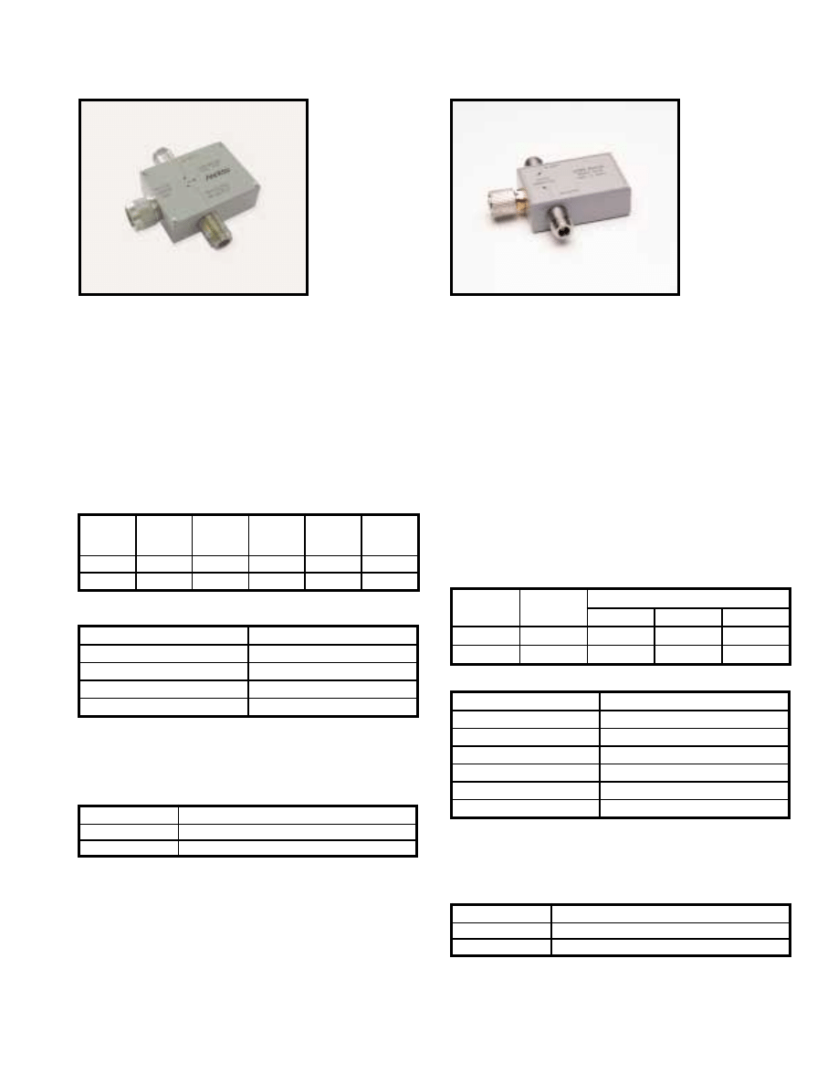
For further information about these products and more, contact us at 1-800-ANRITSU or visit www.us.anritsu.com
37
SWR BRIDGES
61 Series 5 to 2500 MHz and 87 Series 2 to 18 GHz
The 87 Series SWR Bridges are precision, high directivity
measurement components, ideal for SWR and return loss
measurements. Models include a built-in termination, and they are
provided with an overall accuracy equation. These SWR bridges
can be used for making very low-level SWR measurements by
amplifying the RF output prior to detection. Since both the phase
and amplitude of the reflected signal are preserved in the RF output,
these components can also be used to make accurate phase
comparisons in a network analyzer system.
Features
• Broadband 2 to 18 GHz frequency range
• High 38 dB directivity
• Precise GPC-7 test port connector
• Built-in reference termination
Specifications
The 61 series RF SWR Bridges are precision directional devices
designed to make very accurate measurements of SWR. All models
contain a built-in reference termination and preserve phase and
amplitude of the reflected signal.
Features
• 5 to 2500 MHz frequency coverage
• 40 dB directivity
• Built-in reference termination
• Type N test port connectors
Specifications
Ordering information
Please specify model/order number, name, and quantity when ordering.
Ordering information
Please specify model/order number, name, and quantity when ordering.
87A50
61N50
1. Where
ρ
is the measured reflection coefficient.
2. Typically 9 dB at 18 GHz from input to test port.
* Includes the effects of test port reflections and directivity.
ρ
is the measured reflection coeffient.
Temperature range: +25°C ±5°C
Model
Directivity
(dB)
Accuracy
1
2 to 3 GHz
3 to 4 GHz
4 to 18 GHz
87A50
35
0.018 +0.32
ρ
2
0.018 +0.23
ρ
2
0.018 +0.015
ρ
2
87A50-1
38
0.013 +0.32
ρ
2
0.013 +0.23
ρ
2
0.013 +0.015
ρ
2
Frequency range
2 to 18 GHz
Insertion loss
6.5 dB nominal
2
Maximum input power
0.5W
Test port connector
GPC-7
Input and output connector
Type N(f)
Dimensions
7.3 x 5.2 x 2.9 cm plus connectors
Weight
340g
Model/Order No.
Name
87A50
SWR Bridge, 2 to 18 GHz, GPC-7, 35 dB directivity
87A50-1
SWR Bridge, 2 to 18 GHz, GPC-7, 38 dB directivity
Model/Order No.
Name
61N50
SWR Bridge, 5 to 2500 MHz, Type N(m), 40 dB directivity
61NF50
SWR Bridge, 5 to 2500 MHz, Type N(f), 40 dB directivity
Model
Frequency
range
(MHz)
Test port
connector
Directivity
(dB)
Impedance
(Ohms)
Accuracy*
61N50
5-2500
Type N(m)
40
50
0.01 + 0.09
ρ
2
61NF50
5-2500
Type N(f)
40
50
0.01 + 0.09
ρ
2
Insertion loss
6.5 dB nominal from input to test port
Maximum input power
0.5W
Input and output connectors
Type N(f)
Dimensions
6.7 x 5.1 x 2.54 cm (excluding connectors)
Weight
340g
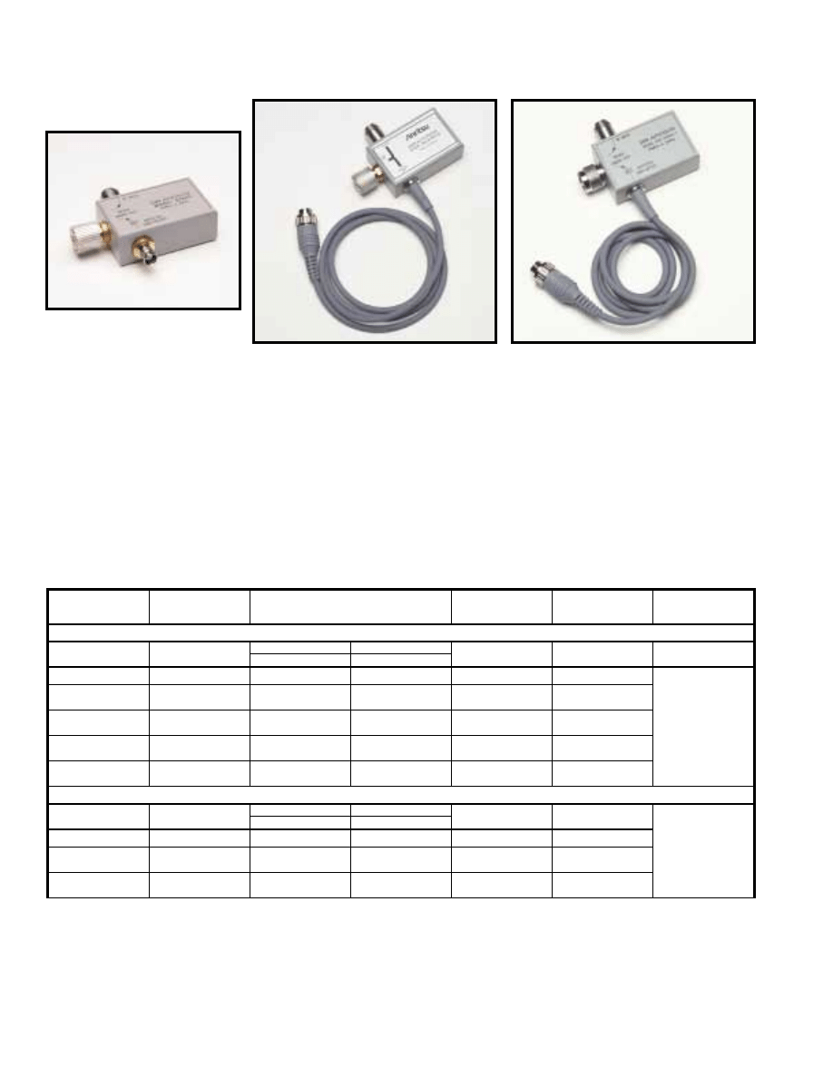
560-97N50
➀
Where
ρ
is the reflection coefficient being measured.Accuracy includes the effects of test port reflections and directivity.
➁
Input Connector: Type N Female
➂
Plus connectors and cable
Temperature range: +25°C ±5°C
For further information about these products and more, contact us at 1-800-ANRITSU or visit www.us.anritsu.com
38
SWR AUTOTESTERS
97 Series and 560-97, 560-98 Series 10 MHz to 50 GHz
97A50
560-97A50
The Series 97, 560-97 and 560-98 SWR Autotesters integrate a high
directivity bridge, a detector, a low reflection test port, and a
precision reference termination. The 560-97 and -98 Series units are
broadband microwave measurement components that are used with
the Model 56100A Scalar Network Analyzer and with Series
54100A Scalar Measurement System for making fixed-frequency
and swept-frequency return loss (SWR) measurements. Return loss
measurements are used over a wide range of radio and microwave
frequencies to check the performance of systems, subsystems, and
microwave components such as amplifiers, directional couplers,
attenuators, filters, splitters, and terminations.
560-97, 98 Series SWR autotester features
• Up to 40 dB directivity
• 10 MHz to 50 GHz range
• Test port connectors to fit most measurement applications;
avoids use of adapters
97 Series SWR autotester features
• High 40 dB directivity
• Low test port reflections
• Broadband 10 MHz to 18 GHz frequency range
• Small package including bridges, termination, and detector
• Selection of GPC-7, WSMA, or Type N test port connectors
Specifications
Continued on next page
Models
Directivity (dB)
Accuracy
➀
Frequency
Sensitivity (dB)
Test Port Connection
Physical
97 Series SWR Autotesters, 10 MHz to 18 GHz
➁
97A50
36
10 MHz-8 GHz
0.016 ±0.06
ρ
2
8-18 GHz
0.016 ±0.10
ρ
2
±1.5 max.
GPC-7
97A50-1
40
0.010 ±0.06
ρ
2
0.010 ±0.10
ρ
2
±1.5 max.
GPC-7
Dimensions
7.6 x 5 x 2.8 cm
plus connectors
Weight: 340 g
97N50
97NF50
35
0.018 ±0.08
ρ
2
0.018 ±0.12
ρ
2
±1.5 max.
Type N (m)
Type N (f)
97N50-1
97NF50-1
38
0.013 ±0.08
ρ
2
0.013 ±0.12
ρ
2
±1.5 max.
Type N (m)
Type N (f)
97S50
97SF50
35
0.018 ±0.08
ρ
2
0.018 ±0.12
ρ
2
±1.5 max.
WSMA (m)
WSMA (f)
97S50-1
97SF50-1
38
0.013 ±0.08
ρ
2
0.013 ±0.12
ρ
2
±1.5 max.
WSMA (m)
WSMA (f)
560-97 Series SWR Autotesters, 10 MHz to 18 GHz
➁
560-97A50
36
0.01-8 GHz
0.013 ±0.08
ρ
2
8-18 GHz
0.016 ±0.10
ρ
2
±1.2
GPC-7
Dimensions
➂
7.6 x 5 x 2.8 cm
plus connectors
Weight: 340 g
560-97A50-1
40
0.010 ±0.06
ρ
2
0.010 ±0.10
ρ
2
±1.2
GPC-7
560-97N50
560-97NF50
35
0.018 ±0.08
ρ
2
0.018 ±0.12
ρ
2
±1.5
Type N (m)
Type N (f)
560-97N50-1
560-97NF50-1
38
0.013 ±0.08
ρ
2
0.013 ±0.12
ρ
2
±1.5
Type N (m)
Type N (f)
For further information about these products and more, contact us at 1-800-ANRITSU or visit www.us.anritsu.com
39
SWR AUTOTESTERS
97 Series and 560-97, 560-98 Series 10 MHz to 50 GHz
Ordering information
Please specify model/order number, name, and quantity when ordering.
All Models:
Input Port Impedance: 50
Ω
Detector Output Polarity: Negative
Maximum Power Input: 0.5 watts (+27 dBm) (560-98C50A: +24 dBm)
Insertion Loss (from input to test port): 6.5 dB nominal
Output Time Constant: 2 ms
Cable Length: 122 cm (4 ft.)
➀
Where
ρ
is the reflection coefficient being measured.Accuracy includes the effects of test port reflections and directivity.
➁
Input Connector: Ruggedized Type K Female
➂
Input Connector: Ruggedized Type V Female
➃
Plus connectors and cable
➄
When used with 18A50 Airline
➅
When used with 19K50 Airline
Models
Directivity (dB)
Accuracy
➀
Freq. Sensitivity
(dB)
Test Port
Connection
Physical
560-98 Series SWR Autotesters, 10 MHz to 40 GHz
➁
560-98S50
560-98SF50
37
36
0.01-8 GHz
8-18 GHz
0.014 ±0.01
ρ
2
18-26.5 GHz
0.016 ±0.13
ρ
2
26.5-40 GHz
±2.0
WSMA (m)
WSMA (f)
Dimensions
➃
:
1.9 x 3.8 x 2.9 cm
Weight: 198 g
560-98S50-1
560-98SF50-1
40
38
0.010 ±0.07
ρ
2
0.010 ±0.01
ρ
2
0.013 ±0.13
ρ
2
±2.0
WSMA (m)
WSMA (f)
560-98K50
560-98KF50
35
32
30
0.018 ±0.07
ρ
2
0.018 ±0.07
ρ
2
0.026 ±0.15
ρ
2
0.032 ±0.18
ρ
2
±3.0
Type K (m)
Type K (f)
560-98 Series SWR Autotesters, 10 MHz to 50 GHz
➂
560-98VA50
560-98VFA50
30
0.01-50 GHz
0.032 ±0.11
ρ
2
±4.0
Type V (m)
Type V (f)
Dimensions
➃
:
2.2 x 6.6 x 5.3 cm
Weight: 198 g
560-97, 560-98 Offset SWR autotesters, 10 Mhz to 40 GHz
560-97A50-20
20
500 MHz-18 GHz
➄
0.0015
±2.5
GPC-7
Dimensions
➃
:
7.6 x 5.1 x 2.8 cm
Weight: 340 g
560-98KF50-15
15
800 MHz-40 GHz
➅
0.0100
±4.0
Type K (m)
Dimensions
➃
:
2.2 x 6.6 x 5.3 cm
Weight: 198 g
Model/Order No.
Name
SWR Autotester
97A50
10 MHz to 18 GHz, GPC-7, 36 dB directivity
97A50-1
10 MHz to 18 GHz, GPC-7, 40 dB directivity
97N50
10 MHz to 18 GHz, N(m), 35 dB directivity
97N50-1
10 MHz to 18 GHz, N(m), 38 dB directivity
97NF50
10 MHz to 18 GHz, N(f), 35 dB directivity
97NF50-1
10 MHz to 18 GHz, N(f), 38 dB directivity
97S50
10 MHz to 18 GHz, WSMA(m), 35 dB directivity
97S50-1
10 MHz to 18 GHz, WSMA(m), 38 dB directivity
97SF50
10 MHz to 18 GHz, WSMA(f), 35 dB directivity
97SF50-1
10 MHz to 18 GHz, WSMA(f), 38 dB directivity
560-97A50
10 MHz to 18 GHz, GPC-7, 50
Ω
, 36 dB directivity
560-97A50-1
10 MHz to 18 GHz, GPC-7, 50
Ω
, 40 dB directivity
560-97N50
10 MHz to 18 GHz, N(m), 50
Ω
, 35 dB directivity
560-97N50-1
10 MHz to 18 GHz, N(m), 50
Ω
, 38 dB directivity
560-97NF50
10 MHz to 18 GHz, N(f), 50
Ω
, 35 dB directivity
560-97NF50-1
10 MHz to 18 GHz, N(f), 50
Ω
, 38 dB directivity
Model/Order No.
Name
SWR Autotester
560-98S50
10 MHz-26.5 GHz, WSMA(m), 50
Ω
, directivity = 37 dB (<18 GHz),
36 dB (18 GHz)
560-98S50-1
10 MHz-26.5 GHz, WSMA(m), 50
Ω
, directivity = 40 dB (<18 GHz),
38 dB (18 GHz)
560-98SF50
10 MHz-26.5 GHz, WSMA(f), 50
Ω
, directivity = 37 dB (< 18 GHz),
36 dB (18 GHz)
560-98SF50-1
10 MHz-26.5 GHz, WSMA(f), 50
Ω
, directivity = 40 dB (< 18 GHz),
38 dB (18 GHz)
560-98K50
10 MHz-40 GHz, K(m), 50
Ω
, directivity = 35 dB (<18 GHz),
32 dB (18 to 26.5 GHz), 30 dB (26.5 GHz)
560-98KF50
10 MHz-40 GHz, K(f), 50
Ω
, directivity = 35 dB (<18 GHz),
32 dB (18 to 26.5 GHz), 30 dB (26.5 GHz)
560-98VA50
10 MHz-50 GHz, V(m), 50
Ω
, directivity = 36 dB (<20 GHz),
30 dB (20 GHz)
560-98VFA50
10 MHz-50 GHz, V(m), 50
Ω
, directivity = 36 dB (<20 GHz),
30 dB (20 GHz)
Offset SWR Autotester
560-97A50-20
10 MHz to 18 GHz, GPC-7, 20 dB offset reference in bridge
560-98KF50-15
10 MHz to 40 GHz, K(f), 15 dB offset reference in bridge
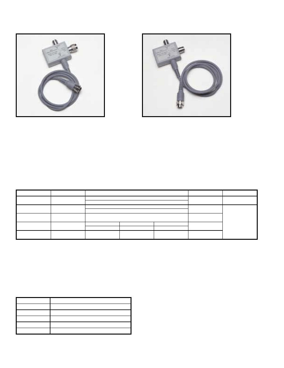
For further information about these products and more, contact us at 1-800-ANRITSU or visit www.us.anritsu.com
40
SWR AUTOTESTERS
5400-6 Series 1 MHz to 3000 MHz
5400-6N50
5400-6NF50
The 5400-6 Series SWR Autotesters integrate a high directivity
bridge, a detector, a low reflection test port, a precision reference
termination, and a connecting cable. They are used with the
Model 56100A Scalar Network Analyzers and with Series 54100A
Scalar Measurement Systems for making fixed-frequency and
swept-frequency return loss (SWR) measurements. Return loss
measurements are used over a wide range of radio and microwave
frequencies to check the performance of systems, subsystems, and
microwave components such as amplifiers, directional couplers,
attenuators, filters, splitters, and terminations.
All Models:
Input Port Impedance: 50
Ω
(Except as Noted)
Detector Output Polarity: Negative
Maximum Power Input: 0.5 watts (+27 dBm)
Insertion Loss (from input to test port): 6.5 dB nominal
Output Time Constant: 2 ms
Cable Length: 122 cm (4 ft.)
➀ Where
ρ
is the reflection coefficient being measured. Accuracy includes the effects of test port reflections and directivity.
➁ Input Connector: BNC Female
➂ Input Connector: Type N Female
➃ Plus connectors and cable
➄ Impedance 75
Ω
Temperature range: +25°C ±5°C
Ordering information
Please specify model/order number, name, and quantity when ordering.
Features
• 40 dB directivity.
• 1 MHz to 3000 MHz range
• F, N, or BNC type test port connectors
Specifications
Models
Directivity (dB)
Accuracy
➀
Test Port Connection
Physical
5400-67FF75
➁➄
40
10-1000 MHz
0.010 ±0.01
ρ
2
F (f)
5400-6B50B
➂
5400-6BF50B
➂
40
1-1500 MHz
0.010 ±0.01
ρ
2
BNC (m)
BNC (f)
Dimensions
➃
:
2.5 x 5.1 x 7.0 cm
Weight: 255 g
5400-6B75B
➂➄
5400-6BF75B
➂➄
40
0.010 ±0.10
ρ
2
BNC (m)
BNC (f)
5400-6N50
➂
5400-6NF50
➂
40
1-1000 MHz
0.010 ±0.05
ρ
2
1000-3000 MHz
0.010 ±0.05
ρ
2
2000-3000 MHz
0.010 ±0.05
ρ
2
Type N (m)
Type N (f)
5400-6N75
➂➄
5400-6NF75
➂➄
40
0.010 ±0.05
ρ
2
0.010 ±0.05
ρ
2
0.010 ±0.05
ρ
2
Type N (m)
Type N (f)
Model/Order No.
Name
SWR Autotester
5400-6N50
1 to 3000 MHz, Type N(m), 50
Ω
40 dB Directivity
5400-6N75
1 to 3000 MHz, Type N(m), 75
Ω
5400-6NF50
1 to 3000 MHz, Type N(f), 50
Ω
5400-6NF75
1 to 3000 MHz, Type N(f), 75
Ω
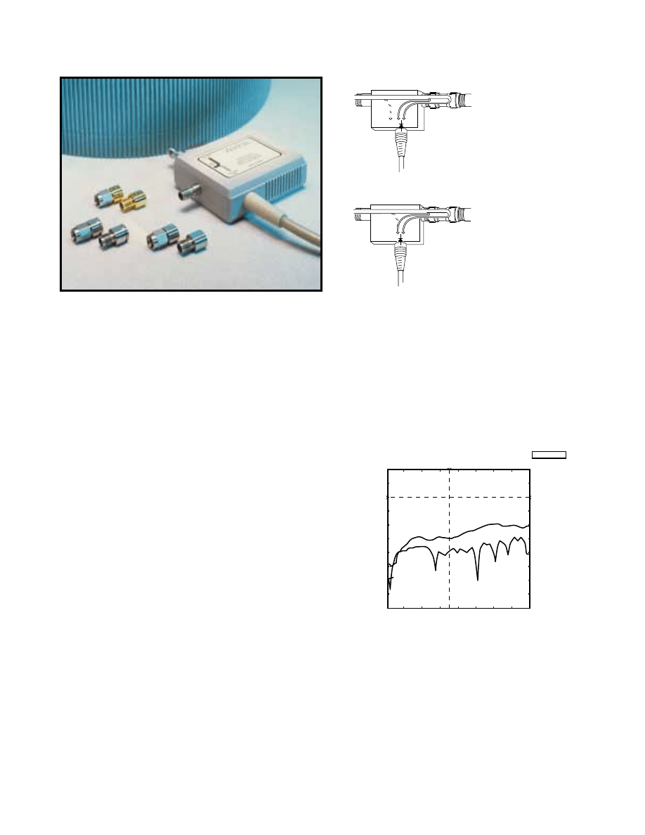
For further information about these products and more, contact us at 1-800-ANRITSU or visit www.us.anritsu.com
41
CONVERTIBLE SWR AUTOTESTER
560-98C50A and Test Port Heads 10 MHz to 40 GHz
560-98C50A
Test Port Heads
INPUT
DUT
CABLE TO
ANALYZER
DETECTOR
STANDARD RF BRIDGE
SWR AUTOTESTOR
TEST PORT
TEST PORT
ADAPTER
Zx
Ea
Ed
Ex
INPUT
CABLE TO
ANALYZER
DETECTOR
CONVERTIBLE
SWR AUTOTESTOR
TEST PORT
PHASE MATCHED
TEST PORT HEAD
Ea
Ed
Ex
A test port adapter on a standard
SWR Autotester or RF Bridge
creates an error vector Ea in
addition to directivity, Ed.
The directivity response of a
Convertible SWR Autotester is
tuned to cancel the vector reflection
response of the phase matched test
port heads.
Convertible SWR Autotesters reduce capital equipment and
maintenance costs. A single Convertible SWR Autotester accurately
measures the Return Loss or SWR of devices with SMA, 3.5 mm, or
K Connector
®
. Six interchangeable test port heads (male and female
for each connector standard) are precision tuned to the Convertible
SWR Autotester’s internal bridge circuit.
The inexpensive test port heads save repair and calibration costs,
because they are interchangeable. Repetitive connect/disconnect
cycles will eventually wear out test port connectors — especially
when excess torque is applied or the connector’s mating surfaces
are rotated against each other.
It is common practice today to avoid the subsequent maintenance
cost by using adapters or “Connector Savers” on the test port of the
directional device (RF Bridge, SWR Autotester, or Directional
Coupler). Unfortunately, the adapters attached to a standard RF
Bridge cause accuracy problems. Directional devices are tuned for
optimum directivity at a specific phase reference point – this
position is called the reference plane. Any test port adapter will
degrade the effective directivity. The Convertible SWR Autotester’s
interchangable test port heads eliminate the accuracy problem.
Adapter errors
In a standard RF bridge, measurement error increases when adapters
or connector savers are used 1) to change the connector’s sex and/or
2) to protect the test port from physical wear. The error effect is
represented as a reduction to directivity. Effective Directivity is
a measurement error term consisting of the directional device’s
directivity plus the SWR response of the test port adapter/
connector saver.
Effective-Directivity is illustrated in the following illustration.
The Directivity Error, E
d
, is caused by deviations from ideal
within the directional device. The adapter’s SWR is represented
by E
a
. Both E
d
and E
a
cause errors in the measurement of
DUT’s return loss, E
x
. This error problem is compounded by
production practices which use poor quality adapters and neglect
calibration/verification cycles.
Accuracy improvement
The Convertible SWR Autotester improves the accuracy of SMA
device tests. It is common practice to test SMA devices with
either 3.5 mm or K test ports.The 3.5 mm and K Connector
®
standards offer rugged, instrument grade connections, but they
are not designed for proper impedance match to a device that
has SMA connectors. SMA, K, and 3.5 mm connectors are
mechanically compatible, but lack electrical compatibility.The
resulting connector mismatch causes a 10 to 15 dB degradation
in measurement directivity.
The above graph illustrates the degradation to directivity when
a K Connector
®
test port is used to measure a precision SMA device.
A 3.5 mm interface causes similar errors. The directivity was
measured using the precision return loss mode on a 54100A Series
Network Analyzer.
Model: 54169A
2: K-SMA CONNEC(B) 10.0 dB/DIV OFFSET 0.0 dB
1: K-K CONNECTN(B) 10.0 dB/DIV OFFSET 0.0 dB
START: 0.5000 GHz
STOP: 40.0000 GHz
5 GHz/DIV
401pts
LEVEL: 0.0 dBm
CURSOR
1: -38.89 dB
2: -29.51 dB
17.6286 GHz
2
1
K-SMA
K - K
The Directivity of a K - K connector interface is far
superior to a mismatched K - SMA connection
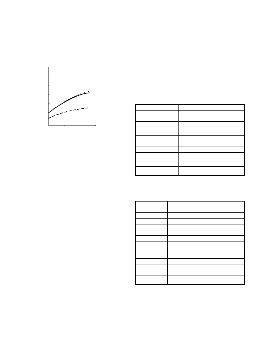
For further information about these products and more, contact us at 1-800-ANRITSU or visit www.us.anritsu.com
42
CONVERTIBLE SWR AUTOTESTER
560-98C50A and Test Port Heads 10 MHz to 40 GHz
K - SMA or 3.5 mm - SMA interfaces.
Electrically, the convertible SWR Autotester provides a nearly
perfect 50
Ω
interface when connected to SMA devices – resulting in
a typical 10 dB improvement in effective directivity performance as
compared to other SMA compatible connectors.
0.01
10
20
30
Frequency, GHz
-30
-40
-60
Connector Interface Return Loss, dB
-50
-20
-10
0
K (2.92 mm) to SMA
Interface
3.5 mm to SMA
Interface
SMA to SMA
Interface
The Convertible SWR Autotester with SMA Test Port Head provides
significantly better directivity performance than test components
with either K (2.92 mm) or 3.5 mm test port connectors.
SMA connections to either K (2.92 mm) or 3.5 mm connectors are
inherently capacitive. Both K and 3.5 mm connectors use air
dielectric. The Teflon
®
or foam polyethylene dielectric common
to SMA connectors have different dielectric constants than air.
Thus, the coaxial dimensions of the center and outer conductors
must also be different to maintain a 50
Ω
transmission line
impedance. Since the K and 3.5 mm connector standards specify
flush pin depths, a non-50
Ω
capacitance develops between their
relatively thick outer conductors to the center pin of an SMA
connected device.
Anritsu’s 25S50 and 25SF50 SMA Test Port Heads include an
inductive connection to SMA connectors by virtue of a slight air gap
at the center pin interface. The air gap negates excess capacitance
caused by the 50
Ω
dimensional transition from the test port head's
air dielectric to the SMA connector's Teflon
®
dielectric.
SMA connectors are not used as a precision instrumentation
connector for three important reasons. First, the dielectric tends to
expand and contract slightly with temperature and humidity
conditions; thus, it is difficult to adhere to dimensional standards
traceability (typically, precision air lines are used as primary or
secondary reference standards) over a reasonable range of
manufacturing floor conditions. Second, as an inexpensive connector
type, many manufacturers have taken liberties in the specification of
dimensions, tolerances, dielectric types and metallurgic content. A
precision standard for SMA connector design is not recognized by
the microwave industry. Finally, SMA designs suffer from reliability
problems when subjected to multiple connections. Center pins can
back out easily and the thin outer conductor wall is easily crushed
when subjected to excessive torque.
* The Convertible SWR Autotester must be used with a test head.
Ordering information
Please specify model/order number, name, and quantity when ordering.
The Convertible SWR Autotester solves these problems. Air
dielectric is used to eliminate the temperature and humidity
variations suffered by Teflon
®
and other dielectrics. Dimensional
tolerances and metallic composition are clearly specified in the
product design and center pin dimensions are phase matched. Air
dielectric also allows use of thicker outer conductors, drastically
decreasing potential deformation from excessive torque.
The Convertible SWR Autotester reduces maintenance costs without
using error prone test port adapters or connector savers.
Accuracy for SMA device test is also improved because the test port
head is properly compensated for operation with standard SMA
connector dimensions.
Specifications
Temperature range: +25°C ±5°C
Frequency Range
0.01 to 40 GHz
Directivity
> 34 dB 0.01 to 20 GHz
> 32 dB 20.0 to 26.5 GHz
> 29 dB 26.5 to 40.0 GHz
Test Port Match
> 21 dB 0.01 to 20.0 GHz
> 18 dB 20.0 to 40.0 GHz
Maximum Input Power
+ 27 dBm
Source Input to
Test Port Isolation
7.0 dB to 9.0 dB nominal insertion loss,
frequency dependent.
Impedance
50
Ω
Input Connector
K(f), 2.92 mm with ruggedized threads
Compatibility
The 560-98C50 is compatible with the 560, 560A, 561,
5400A, 56100A, 562, 54100A and 54000A analyzers.
Dimensions
Autotester: 7.3 cm x 5.3 cm x 2.3 cm
Test Port Heads: 16 mm(L) x 9 mm (dia.)
Model/Order No.
Name
560-98C50A*
Convertible SWR Autotester
Open/Shorts
22K50
Male Open/Short, (Included with 560-98C50A purchase.)
22KF50
Female Open/Short, (Not included with 560-98C50A purchase.)
Test Port Heads
25S50
Precision Matched WSMA male
25SF50
Precision Matched WSMA female
25L50
Precision Matched 3.5 mm male
25LF50
Precision Matched 3.5 mm female
25K50
Precision Matched K male
25KF50
Precision Matched K female
25SKF50
Precision Matched Set, WSMA male & female, K male & female
25SLF50
Precision Matched Set, WSMA male & female,
3.5 mm male & female, K Connctor male & female
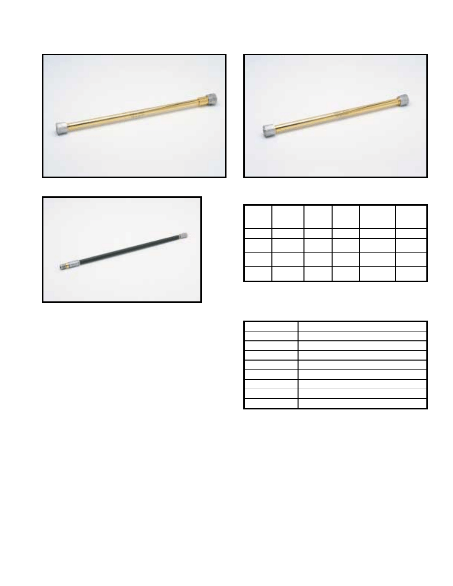
For further information about these products and more, contact us at 1-800-ANRITSU or visit www.us.anritsu.com
43
AIRLINES
18, 19 Series 2 to 40 GHz
The 18 and 19 Series Precision Airlines are the most accurate
impedance standards available today, and they are the recognized
traceability path for impedance at high frequencies. Anritsu airlines
are a critical component when measuring accurate impedances,
enabling measurements down to 1.006 SWR to 18 GHz,1.01 SWR
to 26.5 GHz, and 1.02 SWR to 40 GHz.
A beadless connector is used at the measurement end to provide a
minimum reflection connection. The other end is beaded to keep the
center conductor captive, thus fixing the reference plane at the
beadless end.
Features
• Virtually lossless gold over silver plating
• Provide impedance traceability to NIST
• Enable measurements down to 1.006 SWR to 18 GHz,
1.01 SWR to 26.5 GHz, and 1.02 SWR to 40 GHz
Ordering information
Please specify model/order number, name, and quantity when ordering.
Specifications
18N50
18A50
19S50
Temperature range: +25°C ±5°C
Model
Frequency
range (GHz)
Test port
connector
Beaded
port
connector
SWR
(test port)
Dimensions
L(cm) x
dia(cm)
18A50
0.5 to 18
GPC-7
GPC-7
1.003
30 x 0.7
18N50
18NF50
0.5 to 18
N(m)
N(f)
GPC-7
1.006
30 x 0.7
19S50
19SF50
0.8 to 26.5
WSMA(m)
WSMA(f)
WSMA(m)
1.006 to 18 GHz
1.010 to 26.5 GHz
25 x 0.35
19K50
19KF50
0.8 to 40
K(m)
K(f)
K(m)
1.020
15 x 0.29
Model/Order No.
Name
Precision Air Line
18A50
0.5 to 18 GHz, 50
Ω
, GPC-7
18N50
0.5 to 18 GHz, 50
Ω
, N (m)
18NF50
0.5 to 18 GHz, 50
Ω
, N (f)
19K50
0.8 to 40 GHz, 50
Ω
, K(m)
19KF50
0.8 to 40 GHz, 50
Ω
, K(f)
19S50
0.8 to 26.5 GHz, 50
Ω
19SF50
0.8 to 26.5 GHz, 50
Ω
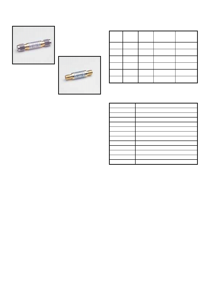
For further information about these products and more, contact us at 1-800-ANRITSU or visit www.us.anritsu.com
44
OPEN/SHORTS
22 Series DC to 50 GHz
22K50
22KF50
The 22 Series Open/Shorts are used on the test port of an SWR
Autotester or SWR bridge to establish a full reflection reference
for accurate SWR measurements. When used with scalar network
analyzers, the open and short reflections over a swept frequency
range can be automatically averaged to enhance measurement
accuracy. All models consist of an open on one end and a short
on the other.
Features
• Single gold-plated component providing full open and short
reflections for accurate SWR measurements
• DC to 50 GHz frequency coverage
• GPC-7, Type N, WSMA, K Connectors
®
and V Connectors
®
• 50
Ω
or 75
Ω
impedance
Specifications
Ordering information
Please specify model/order number, name, and quantity when ordering.
Temperature range: +25°C ±5°C
Model
Frequency
range
(GHz)
Test port
connector
Characteristic
impedance
(Ohms)
Dimensions
L(cm) x dia(cm)
22N75
22NF75
DC to 2
N(m)
N(f)
75
6.3 x 1.8
4.9 x 1.6
22N50
22NF50
DC to 18
N(m)
N(f)
50
6.3 x 1.8
4.9 x 1.6
22A50
DC to 18
GPC-7
50
3.8 x 1.6
22S50
22SF50
DC to 26.5
WSMA(m)
WSMA(f)
50
4.2 x 0.8
3.5 x 0.8
22K50
22KF50
DC to 40
K(m)
K(f)
50
4.2 x 0.8
3.5 x 0.8
22V50
22VF50
DC to 50
V(m)
V(f)
50
3.6 x 0.8
2.8 x 0.8
Model/Order No.
Name
Open/Short
22N50
DC to 18 GHz, N(m), 50
Ω
22NF50
DC to 18 GHz, N(f), 50
Ω
22N75
DC to 3 GHz, N(m), 75
Ω
22NF75
DC to 3 GHz, N(f), 75
Ω
22A50
DC to 18 GHz, GPC-7 connector, 50
Ω
22K50
DC to 40 GHz, K(m), 50
Ω
22KF50
DC to 40 GHz, K(f), 50
Ω
22S50
DC to 26.5 GHz, WSMA(m), 50
Ω
22SF50
DC to 26.5 GHz, WSMA(f), 50
Ω
22V50
DC to 50 GHz, V(m), 50
Ω
22VF50
DC to 50 GHz, V(f), 50
Ω
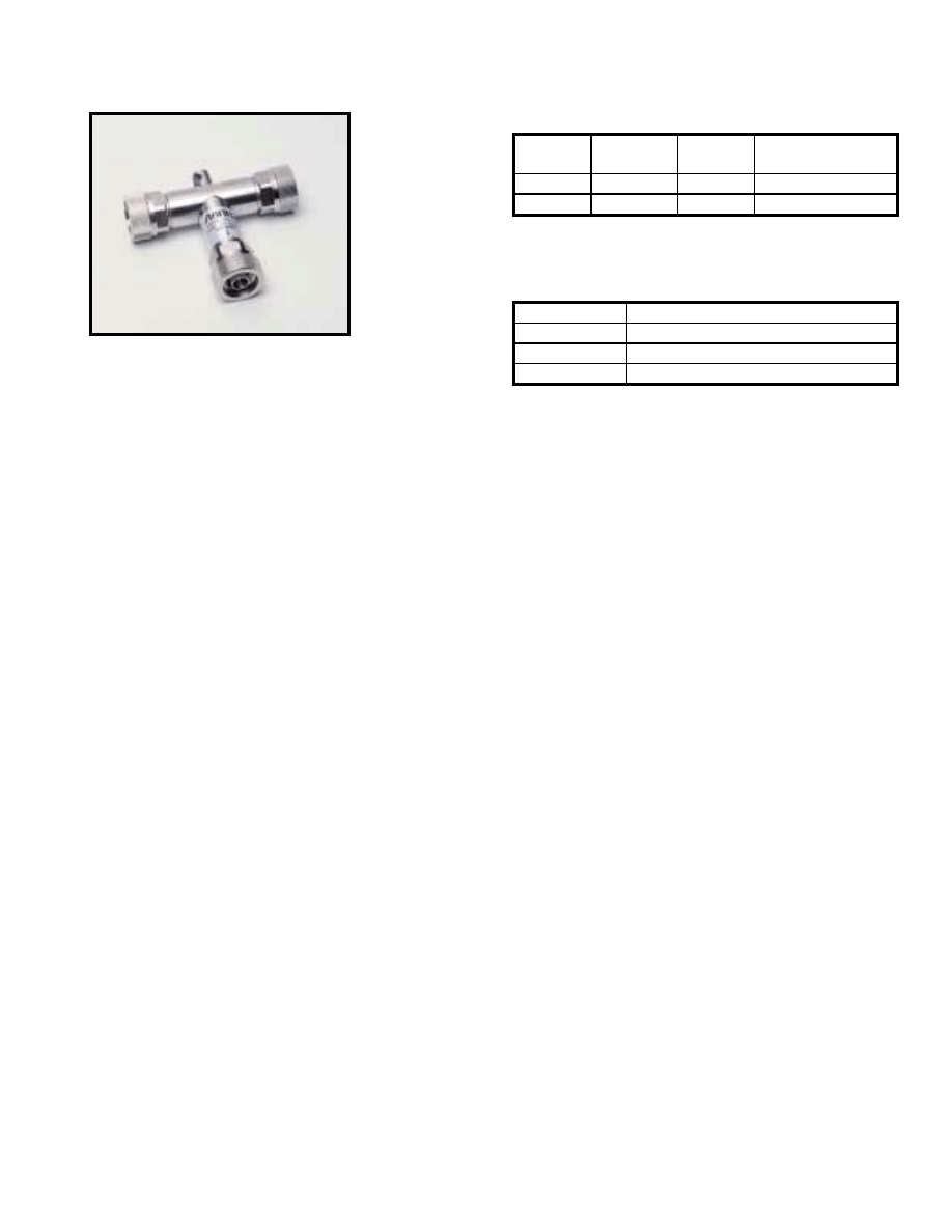
For further information about these products and more, contact us at 1-800-ANRITSU or visit www.us.anritsu.com
45
OPEN/SHORTS/LOADS
OSL Series DC to 4 GHz
OSLN50LF
The OSL series open/short/load are used on the test port of the
Site Master
™
Series of handheld instruments to establish a reference
for accurate measurement. When used with a Site Master, the
open/short and load reflection over a swept frequency range can be
automatically averaged to enhance measurement accuracy. OSL
series Open/short/load comes in both N(Male) and N (Female)
connector configuration and consist open on one end, short
on other and Load on the tee section.
Features
• Single Nickel Plated Component providing full open, short
and load reflections for accurate measurements.
• DC to 4 GHz frequency coverage
• Type N(Male) and N(Female) connector configuration
• 50
Ω
Impedence
Ordering information
Please specify model/order number, name, and quantity when ordering.
Specifications
Temperature range: +25°C ±5°C
Model/Order No.
Name
Open/Short/Load
OSLN50LF
DC to 4 GHz, N(m), 50
Ω
OSLNF50LF
DC to 4 GHz, N(f), 50
Ω
Model
Frequency
range (GHz)
Test port
connector
Characteristic impedance
(Ohms)
OSLN50LF
DC to 4
N(m)
50
OSLNF50LF
DC to 4
N(f)
50
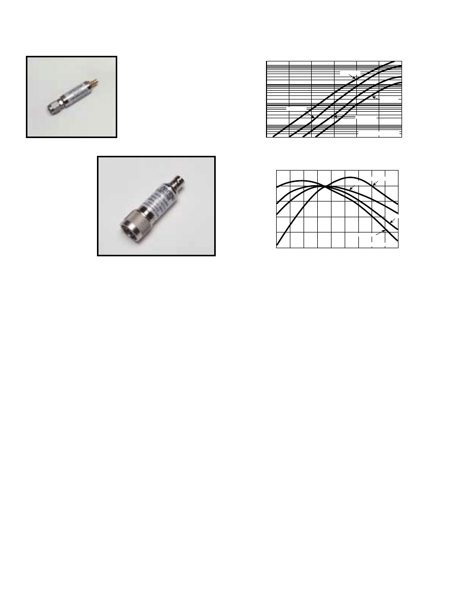
For further information about these products and more, contact us at 1-800-ANRITSU or visit www.us.anritsu.com
46
MICROWAVE DETECTORS
70, 75 Series 100 kHz to 50 GHz
Within the 70 or 75 Series product lines, you will find a model
that matches your needs for instrumentation, system, or OEM
applications. By using the latest design and microelectronics
production technologies, Anritsu low-barrier Schottky-diode
detectors outperform others and offer significant cost savings.
Input connector types include Type N, and K Connector
®
(compatible with SMA and 3.5 mm), and V Connector
®
(compatible with 2.4 mm). In addition to frequency coverage
and price, these detectors are distinguished by their low SWR,
flat frequency response, and close output-voltage tracking over
a wide dynamic range.
Features
• Broadband coverage, 10 MHz to 50 GHz with a Single Detector
• K Connector
®
compatible with SMA and 3.5 mm
• V Connector
®
compatible with 2.4 mm
• Lowest SWR: 1.33 to 20 GHz, 1.5 to 40 GHz
• Flat Response: ±0.5 dB to 20 GHz ±1.5 dB to 40 GHz
• Best Value for Instrumentation, system, and OEM applications
• Low price and availability from stock
R
L
= Load resistance
R
L
= 50
R
L
= 50 k
R
L
= 1 k
R
L
= 200
10
1
0.1
–10
–20
–30
–40
Output v
oltage (mV)
0
+10
+20
Input power (dBm)
1000
100
+1
0
–1
–2
–3
–4
–10
0
+10
+20
+30
+40
+50
+60
+70
+80
Temperature (
˚
C)
Change in sensitivity (dB)
R
L
= Load resistance
R
L
= 40 k
R
L
= 10 k
R
L
= 1 k
R
L
= 5 k
Typical sensitivity
Typical sensitivity change
75N50B
70KA50
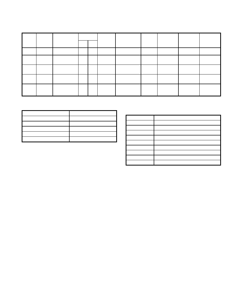
For further information about these products and more, contact us at 1-800-ANRITSU or visit www.us.anritsu.com
47
MICROWAVE DETECTORS
70, 75 Series 100 kHz to 50 GHz
Dimensions
Ordering information
Please specify model/order number, name, and quantity when ordering.
*Upper frequency limit (GHz):
≤
8,
≤
12.4,
≤
18,
≤
26.5,
≤
40
**Frequency response tracking (dB): ±0.2, ±0.3, ±0.6, ±0.8, ±1.2
Specifications
Model
Frequency
range
Flatness
(dB)
Connectors
Impedance
(Ohms)
SWR (Maximum)
Low level
sensitivity
at –30 dBm
(mV/µW)
High level
sensitivity at
+13 dBm
(Volts, Min.)
Input
maximum
(mW)
Output
capacitance
(pF)
In
Out
70KA50
0.01 to
20 GHz
±0.6
K(m)
SMC(f)
50
1.33
0.6
1
100
30
70KC50
0.01 to
40 GHz
±0.5 to 20 GHz
±1.0 to 26.5 GHz
±1.5 to 40 GHz
K(m)
SMC(f)
50
1.33 to 20 GHz
1.50 to 26.5 GHz
1.90 to 40 GHz
0.4
1
100
30
75N50B
0.01 to
18 GHz
±0.3 to 12.4 GHz
±0.6 to 18 GHz
N(m)
BNC(f)
50
1.15 to 4.5 GHz
1.30 to 15 GHz
1.39 to 18 GHz
0.35
1
100
30
75KC50
0.01 to
40 GHz
±0.5 to 20 GHz
±1.0 to 26.5 GHz
±1.5 to 40 GHz
K(m)
BNC(f)
50
1.33 to 20 GHz
1.50 to 26.5 GHz
1.90 to 40 GHz
0.4
1
100
30
75VA50
0.01 to
50 GHz
±0.5 to 20 GHz
±1.0 to 26.5 GHz
±1.5 to 40 GHz
±3 to 50 GHz
V(m)
BNC(f)
50
1.33 to 20 GHz
1.50 to 26.5 GHz
1.90 to 40 GHz
2.1 to 50 GHz
0.4
1
100
30
Model
Dimensions L(cm) x dia(cm)
70KA50
4.6 x 1.0
70KC50
4.6 x 1.0
75N50B
6.4 x 1.8
75KC50
4.6 x 1.0
75VA50
4.6 x 1.0
Model/Order No.
Name
Microwave Detector
70KA50
10 MHz to 20 GHz, K(m) input, SMC(f) output, 50
Ω
70KC50
10 MHz to 40 GHz, K(m) input, SMC(f) output, 50
Ω
75KC50
10 MHz to 40 GHz, K(m) input, BNC(f) output, 50
Ω
75N50B
10 MHz to 18.5 GHz, N(m) input, BNC(f) output, 50
Ω
75VA50
10 MHz to 50 GHz, V(m) input, BNC(f) output, 50
Ω
Options
Option 2 (75KC50)
Matching frequency response of two detectors
Option 3 (75KC50)
Matching frequency response of three detectors
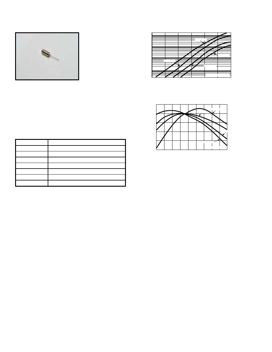
For further information about these products and more, contact us at 1-800-ANRITSU or visit www.us.anritsu.com
48
FIELD REPLACEMENT DIODE MODULE
A16176
R
L
= Load resistance
R
L
= 50
R
L
= 50 k
R
L
= 1 k
R
L
= 200
10
1
0.1
–10
–20
–30
–40
Output v
oltage (mV)
0
+10
+20
Input power (dBm)
1000
100
+1
0
–1
–2
–3
–4
–10
0
+10
+20
+30
+40
+50
+60
+70
+80
Temperature (
˚
C)
Change in sensitivity (dB)
R
L
= Load resistance
R
L
= 40 k
R
L
= 10 k
R
L
= 1 k
R
L
= 5 k
Typical sensitivity
Typical sensitivity change
Field replaceable diode modules provide field replacements for
damaged diodes, virtually eliminating down time. To avoid all
degradation in performance when a diode is replaced in the field,
all replacement modules include the thin-film matching circuit.
Performance after replacement cannot be distinguished from that
of a new detector.
Ordering information
Please specify model/order number, name, and quantity when ordering.
Model/Order No.
Name
Diode module
10-108
71 & 73 Series
10-75
75A50
A16176
70K Series (>=20 GHz) and 75K Series (>=20 GHz)
A16177
70K Series (<=20 GHz) and 75K Series (<=20 GHz)
A18735
74N50B
B16132
75N50B
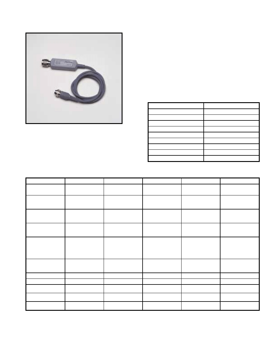
For further information about these products and more, contact us at 1-800-ANRITSU or visit www.us.anritsu.com
49
MICROWAVE DETECTORS
5400-71, 560-7 Series 1 MHz to 50 GHz
The Anritsu 560-7 and 5400-71 Series RF Detectors are used
with the Model 56100A Scalar Network Analyzer and with
Series 54100A Scalar Measurement System for making coaxial
transmission loss or gain and power measurements. They are also
used with the Site Master
®
and Cable Mate
®
Series Personal
SWR/RL and Fault Location Testers for making
power measurements.
Features
• Zero-biased Schottky diodes
• –55 dBm to +16 dBm range
Specifications
*
* The maximum input power is + 20 dBm for all microwave detectors with the exception of 5400-71N75L.
** The input of the 5400-71N75L is designed to extend the damage level to 1W (+30 dBm).
Compression begins at 10 dBm <0.05 GHz, 15 dBm <1 GHz, or 20 dBm <1.2 GHz.
Ordering information
Please specify model/order number, name, and quantity when ordering.
5400-71N50
Temperature range: 0°C to +70°C
Model/Order No.
Name
Microwave Detector
5400-71N50
1 to 3000 MHz, N(m), 50
Ω
5400-71N75
1 MHz to 3 GHz, N(m), 75
Ω
560-7A50
10 MHz to 18 GHz, GPC-7, 50
Ω
560-7K50
10 MHz to 40 GHz, K(m), 50
Ω
560-7N50B
10 MHz to 20 GHz, N(m), 50
Ω
560-7S50-2
10 MHz to 26.5 GHz, WSMA(m), 50
Ω
560-7S50B
10 MHz to 20 GHz, WSMA(m), 50
Ω
560-7VA50
10 MHz to 50 GHz, V(m), 50
Ω
Model
Frequency range
Impedance
Return loss
Input connector
Frequency response
560-7A50
0.01 to 18 GHz
50
Ω
15 dB, <0.04 GHz
22 dB, <8 GHz
17 dB, <18 GHz
GPC-7
±0.5 dB, 18 GHz
560-7N50B
0.01 to 20 GHz
50
Ω
15 dB, <0.04 GHz
22 dB, <8 GHz
17 dB, <18 GHz
14 dB, <20 GHz
N(m)
±0.5 dB, <18 GHz
±1.25 dB, <20 GHz
560-7S50B
0.01 to 20 GHz
50
Ω
15 dB, <0.04 GHz
22 dB, <8 GHz
17 dB, <18 GHz
14 dB, <20 GHz
WSMA(m)
±0.5 dB, <18 GHz
±1.25 dB, <20 GHz
560-7S50-2
0.01 to 26.5 GHz
50
Ω
15 dB, <0.04 GHz
22 dB, <8 GHz
17 dB, <18 GHz
14 dB, <26.5 GHz
WSMA(m)
±0.5 dB, <18 GHz
±1.25 dB, <26.5 GHz
560-7K50
0.01 to 40 GHz
50
Ω
12 dB, <0.04 GHz
22 dB, <8 GHz
7 dB, <18 GHz
15 dB, <26.5 GHz
14 dB, <32 GHz
13 dB, <40 GHz
K(m)
±0.5 dB, <18 GHz
±1.25 dB, <26.5 GHz
±2.2 dB, <32 GHz
±2.5 dB, <40 GHz
560-7VA50
0.01 to 50 GHz
50
Ω
12 dB, <0.04 GHz
19 dB, <20 GHz
15 dB, <40 GHz
10 dB, <50 GHz
V(m)
±0.8 dB, <20 GHz
±2.5 dB, <40 GHz
±3.0 dB, <50 GHz
5400-71B50
0.001 to 1.5 GHz
50
Ω
20 dB
BNC(m)
±0.2 dB, <1.5 GHz
5400-71B75
0.001 to 1.5 GHz
75
Ω
20 dB
BNC(m)
±0.2 dB, <1.5 GHz
5400-71N50
0.001 to 3 GHz
50
Ω
26 dB
N(m)
±0.2 dB, <1 GHz
±0.3 dB, <3 GHz
5400-71N75
0.001 to 3 GHz
75
Ω
26 dB, <2 GHz
20 dB, <3 GHz
N(m)
±0.2 dB, <3 GHz
±0.3 dB, <3 GHz
5400-71N75L**
0.005 to 1.2 GHz
75
Ω
24 dB
N(m)
±0.2 dB, <1 GHz
±0.5 dB, <1.2 GHz
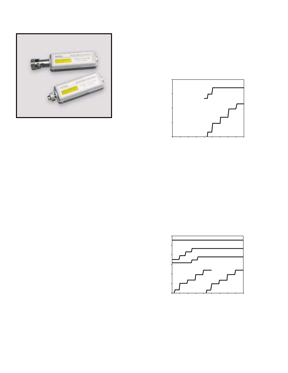
For further information about these products and more, contact us at 1-800-ANRITSU or visit www.us.anritsu.com
50
POWER SENSORS
MA2400A/B Series 10 MHz to 50 GHz
Anritsu thermal sensors have class-leading SWR and built in
EEPROM with calibration factor and linearity correction data.
This results in assured accuracy when measuring any signal.
Anritsu’s fast thermal power sensors improve sensor rise time and
fall time to less than 4.0ms– an order of magnitude faster than
previous thermal sensors. Settled power measurements are now
10 times faster; that means reduced test time.
Standard diode sensors
Diode sensors have greater speed, sensitivity and dynamic range
than thermal sensors (see fig. 2). All Anritsu diode sensors use a
dual diode architecture that gives improved sensitivity and dynamic
range over single diode architectures. The MA2470A Series Power
Sensors 90 dB dynamic range is both fast and accurate. Linearity is
better than 1.8%, typically < 1.0% through 18 GHz.
MA2470A power sensors offer an ideal combination of speed and
dynamic range for general purpose power measurements. A single
sensor replaces the two sensors that were previously required with
sensors limited to 50 dB dynamic range.
The MA2400A/B Series Power Sensors consist of MA247XA
Series Power Sensors, MA246XA/B Series Power Sensors,
MA248XA Series Universal Power Sensors, MA242XA/B Series
Thermal Power Sensors, and MA244XA Series High Accuracy
Power Sensors. These units are broadband microwave measurement
components. All models except the MA246XA/B Series Power
Sensors, are used with the ML2430A Series Power Meters. The
MA246XA/B Series Power Sensors are used with the ML2400A
Series Power Meter only.
Features
• 10 MHz to 50 GHz range
• N, K, and V type RF connectors
• 90 dB dynamic range provides stable power readings
to –70 dBm
• MA244XA Series High Accuracy Power Sensors
contain an additional matching circuit to improve
return loss performance.
• MA242XA/B Series Thermal Power Sensors provide measuring
speeds to 4 ms rise and fall times in addition toexceptional
return loss performance
• MA246XB power sensors have fast 1 millisecond rise and fall
times needed for CDMA measurements
• MA248XA Universal sensors measure average power of
modulated signals such as W-CDMA, multi-tone, etc.
• All MA2481A/B Series Power Sensors contain internal
EEPROMs for storage of calibration data as a function of
frequency, power, and temperature. This allows the power
meter to interpolate and correct readings automatically
Fast thermal sensors
Anritsu’s thermal sensors provide excellent power measurement
accuracy over 50 dB of dynamic range with more speed than any
other thermal sensor available (see fig. 1). Thermal sensors use
Seebeck elements where the combined effect of a thermal gradient
and charge migration between dissimilar metals gives a true reading
of average power on any incident waveform.
MA2472A
MA2475A
MA2470A, Sampling Rate
MA2470A, Reading Rate
MA2470A, GPIB Continuous
Auto-Averaged Readings
Traditional
Diode Sensor
Traditional
Thermal Sensor
100000
10000
1000
100
10
1
0.1
-70
-60
-50
-40
-30
-20
-10
0
10
20
Rdgs/sec
Pin
Fig. 2 Standard Diode Sensors
Fig. 1 Fast Thermal Sensors
MA242XA Series
Thermal Sensors
Traditional
Thermal Sensor
1000
100
10
1
0.1
-70
-60
-50
-40
-30
-20
-10
0
10
20
Rdgs/sec
Pin
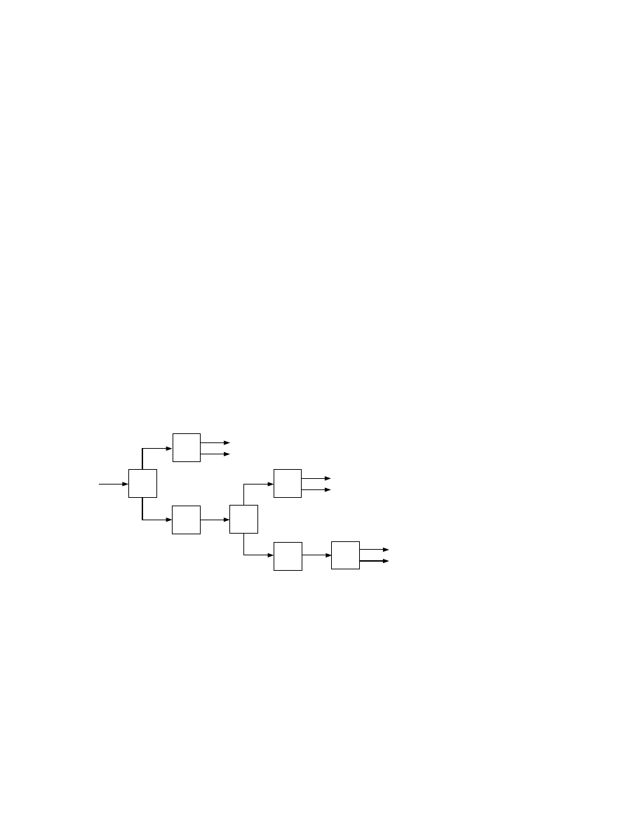
For further information about these products and more, contact us at 1-800-ANRITSU or visit www.us.anritsu.com
51
POWER SENSORS
MA2400A/B/C Series 10 MHz to 50 GHz
Universal power sensors
The new MA2480A series Universal Power Sensors will measure
any modulated or multi-tone signal, thanks to a patented sensor
architecture with three diode pairs (see fig. 3). Universal power
sensors deliver over 80 dB of dynamic range with speed and
accuracy. Average power measurements on WCDMA signals
can now be made without the need for special power meters.
Universal sensors are also ideal for power measurements on other
digitally modulated carriers such as HDTV, DAB or QAM
modulated radio links.
Universal power sensors are also ideal for applications
where multiple signals are present, such as intermodulation
measurements and satellite multi carrier power loading
measurements.
A unique additional capability of the Anritsu Universal power
sensor is the ability to use it as a standard diode sensor for
CW measurements. In this mode the fast response of diode sensors
is maintained across the full dynamic range of the sensor, meaning
that for the majority of users it is the only sensor that they will ever
need – a truly Universal Power Sensor.
High accuracy diode sensors
The Anritsu MA2440A series high-accuracy diode sensors have
a built in 3 dB attenuator to minimize input SWR. They are used
where the best measurement accuracy is required over a large
dynamic range, for example when measuring amplifiers. High
accuracy diode sensors have a dynamic range of 87 dB compared
to the 90 dB of standard diode sensors.
Fast diode sensors
The MA2460C fast diode sensors from Anritsu have a rise
time of 0.6 µs. This, together with a sensor video bandwidth of
1.25 MHz, makes them the ideal solution for power measurements
on N-CDMA (IS-95) signals. The MA2460 sensors must be used
with the ML2407/08A power meter. This combination of meter and
sensor provides fast signal processing and sampling speeds. Average
power, peak power and crest factor on N-CDMA signals can be
measured and displayed. The MA2460 are dual diode sensors that
deliver a greater-than 80 dB dynamic range, which makes them
suitable for both open- and closed-loop power-control testing. The
sensors internal AC detection circuitry gives a guaranteed noise
floor of –60 dBm with typical performance to –70 dBm, even when
measuring CDMA signals.
Pulses down to 1 µs can also be captured and displayed, thanks to
the sensor rise time of 0.6 µs. In profile mode the ML2407A
meter can be used to measure average power across narrow pulses,
an increasingly common test method for amplifiers in digitally
modulated systems.
INPUT
DET B -ve
DET B +ve
DET A -ve
DET A +ve
6dB
Power
Divider
Detector
‘C’
11dB
Pad
6dB
Power
Divider
Detector
‘B’
17dB
Pad
Detector
‘A
DET C -ve
DET C +ve
RF
Fig. 3 Universal Power Sensor
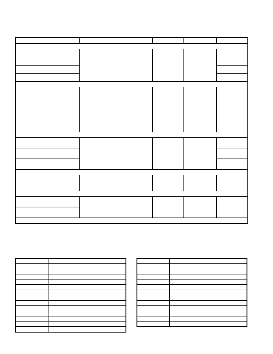
For further information about these products and more, contact us at 1-800-ANRITSU or visit www.us.anritsu.com
52
POWER SENSORS
MA2400A/B Series 10 MHz to 50 GHz
Specifications
1. 0.0 dBm, room temperature.
2. Each MA2400A/B series sensor incorporates precision RF connectors with hexagon coupling nut for attachment by industry standard torque wrench.
3. MA2460A/B Fast Diode Sensors must be used with ML2407/08A Power Meters for NCDMA and Fast Pulse measurements.
Temperature range: +25°C ±5°C
Ordering information
Please specify model/order number, name, and quantity when ordering.
Model
Frequency range
Dynamic range (dBm)
SWR
Rise time
1
(ms)
Sensor linearity
RF connector
2
Standard diode sensors
MA2472A
10 MHz - 18 GHz
–70 to +20
<1.90; 10 - 50 MHz
<1.17; 50 - 150 MHz
<1.12; 0.15 - 2 GHz
<1.22; 2 - 12.4 GHz
<1.25; 12.4 - 18 GHz
<1.35; 18 - 32 GHz
<1.50; 32 - 40 GHz
<1.63; 40 - 50 GHz
<0.004
1.8%, <18 GHz
2.5%, <40 GHz
3.5%, <50 GHz
N (m)
MA2473A
10 MHz - 32 GHz
K (m)
MA2474A
10 MHz - 40 GHz
K (m)
MA2475A
10 MHz - 50 GHz
V (m)
Fast thermal sensors
MA2421B
0.1 MHz - 18 GHz
–30 to +20
<1.10; 0.1 MHz - 2 GHz
<1.15; 2 - 12.4 GHz
<1.20; 12.4 - 18 GHz
<4.0
1.3%, <18 GHz
1.5%, <40 GHz
1.8%, <50 GHz
N (m)
MA2422B
10 MHz - 18 GHz
<1.90; 10 - 50 MHz
<1.17; 50 - 150 MHz
<1.10; 0.15 - 2 GHz
<1.15; 2 - 12.4 GHz
<1.20; 12.4 - 18 GHz
<1.25; 18 - 32 GHz
<1.30; 32 - 40 GHz
<1.40; 40 - 50 GHz
N (m)
MA2423B
10 MHz - 32 GHz
K (m)
MA2424B
10 MHz - 40 GHz
K (m)
MA2425B
10 MHz - 50 GHz
V (m)
High accuracy diode sensors
MA2442A
10 MHz - 18 GHz
–67 to +20
<1.90; 10 - 50 MHz
<1.17; 50 - 150 MHz
<1.08; 0.15 - 2 GHz
<1.16; 2 - 12.4 GHz
<1.21; 12.4 - 18 GHz
<1.29; 18 - 32 GHz
<1.44; 32 - 40 GHz
<1.50; 40 - 50 GHz
<0.004
1.8%, <18 GHz
2.5%, <40 GHz
3.5%, <50 GHz
N (m)
MA2444A
10 MHz - 40 GHz
K (m)
MA2445A
10 MHz - 50 GHz
V (m)
Fast diode sensors
MA2468A
3
10 MHz - 6 GHz
–60 to +20
<1.17; 10 - 150 MHz
<1.12; 0.15 - 2 GHz
<1.22; 2 - 12.4 GHz
<1.25; 12.4 - 18 GHz
< 0.0006
1.8%
N (m)
MA2469B
3
10 MHz - 18 GHz
Universal power sensors
MA2481B
10 MHz - 6 GHz
–60 to +20
< 1.17; 10 - 150 MHz
< 1.12; 0.15 - 2 GHz
< 1.22; 2 - 12.4 GHz
< 1.25; 12.4 - 18 GHz
<0.0004
(with option 1 only)
10 MHz to 6 GHz
3% –60 to +20 dBm
6 to 18 GHz
3% to 18 GHz
3.5% 0 to +20 GHz
3% (1.8% CW with option 1)
N (m)
MA2482A
10 MHz - 18 GHz
MA2480/01
Adds fast CW mode to Universal Power Sensors for high speed measurements of CW signal plus TDMA and pulse measurements.
Model/Order No.
Name
Thermal Sensor
MA2421A
0.1 MHz to 18 GHz
MA2422B
10 MHz to 18 GHz
MA2423B
10 MHz to 32 GHz
MA2424B
10 MHz to 40 GHz
MA2425B
10 MHz to 50 GHz
High Accuracy Sensor
MA2442A
10 MHz to 18 GHz
MA2444A
10 MHz to 40 GHz
MA2445A
10 MHz to 50 GHz
Fast Diode Sensor
MA2468A
10 MHz to 6 GHz
MA2469B
10 MHz to 18 GHz
Model/Order No.
Name
Power Sensor
MA2472A
10 MHz to 18 GHz
MA2473A
10 MHz to 32 GHz
MA2474A
10 MHz to 40 GHz
MA2475A
10 MHz to 50 GHz
MA2481B
Universal Power Sensor, 10 MHz to 6 GHz
MA2482A
Universal Power Sensor, 10 MHz to 18 GHz
MA2480/01
Option 1, Universal Power Sensor CW Option
MA2400/98
Z540/Guide 25 Calibration
MA2400/99
Premium Calibration
MA2497A
Agilent (HP) Sensor adapter
MA2499B
Anritsu Sensor 10 to 12 pin Adapter
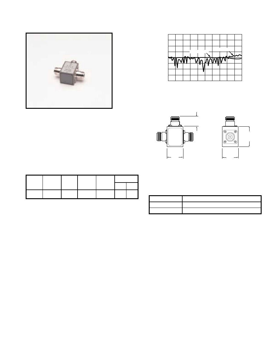
For further information about these products and more, contact us at 1-800-ANRITSU or visit www.us.anritsu.com
53
POWER DIVIDERS
11 Series DC to 3000 MHz
These RF power dividers are symmetrical, three-resistor tee designs
that can be used in applications where signals from DC to 3000 MHz
must be accurately divided. They are available in 50
Ω
or 75
Ω
and
provide excellent amplitude and phase tracking.
Features
• DC to 3000 MHz frequency range
• Excellent amplitude and phase tracking
• 50
Ω
or 75
Ω
Specifications
Frequency (GHz)
0
3
0
2
4
6
8
10
12
0
10
20
30
40
50
60
Typical Return Loss (dB)
Typical Insertion Loss (dB)
Return loss
Insertion loss
11N50B
Insertion loss (typical) /return loss (typical)
31.75
(MAX)
31.75
(MAX)
40.64
(MAX)
17.78
(TYP.)
Dimensions in millimeters
11N50B, 11N75B outline
Ordering information
Please specify model/order number, name, and quantity when ordering.
Maximum Input Power: 1 Watt
Temperature range: 0°C to +70°C
Model
Frequency
range
(MHz)
SWR
Insertion
loss
(dB, max.)
Impedance
(Ohms)
Connectors
Input
Output
11N50B
11N75B
DC to 3000
<1.25
7
50
75
N(f)
N(f)
Model/Order No.
Name
11N50B
Power Divider, 1 MHz to 3 GHz, 50
Ω
11N75B
Power Divider, 1 MHz to 3 GHz, 75
Ω
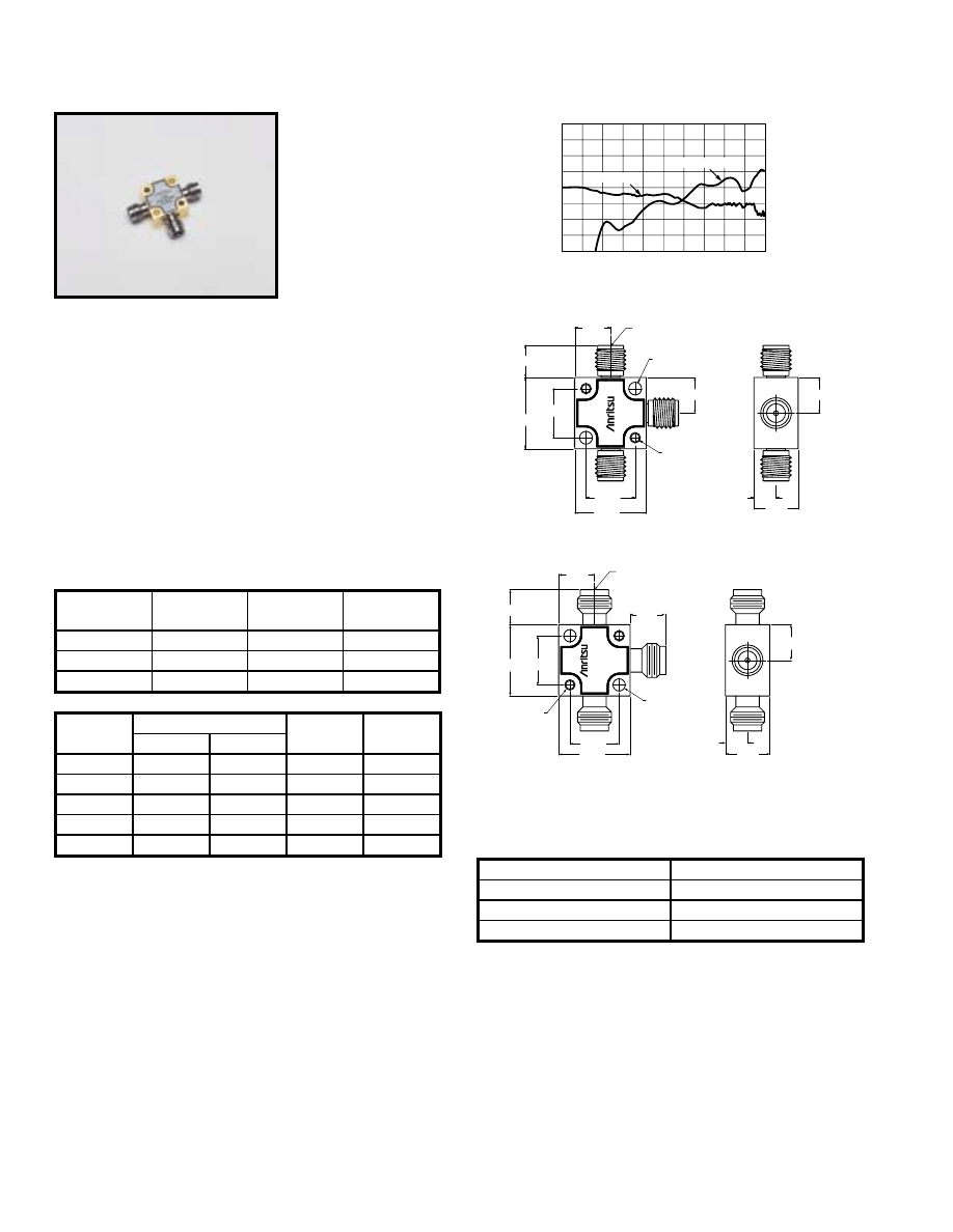
For further information about these products and more, contact us at 1-800-ANRITSU or visit www.us.anritsu.com
54
POWER DIVIDERS
K240, V240 Series DC to 65 GHz
Frequency (GHz)
0
67
0
2
4
6
8
10
12
0
5
10
15
20
25
30
Typical Return Loss (dB)
Typical Insertion Loss (dB)
Return loss
Insertion loss
Insertion loss (typical) /return loss (typical) for V240C
7.4 mm
7.4 mm
1
2
3
14.7 mm
10.2 mm
14.7 mm
10.2 mm
Ø 2.6 mm
2X
2-56 UNC-2B, 2X
9.1 mm
4.6 mm
6.6 mm TYP.
7.4 mm
K CONNECTOR FEMALE
1/4 - 36 UNS - 2A, 3X
K240C
POWER
DIVIDER
DC-40
GHz
Dimensions in Millimeters
K240B, K240C outline
4.6 mm
9.1 mm
2-56 UNC-2B, 2X
Ø 2.6 mm 2X
11.4 mm
6.1 mm
10.2 mm
14.7 mm
10.2 mm
14.7 mm
DC-65 GHz
3
2
1
7.4 mm
7.4 mm
V CONNECTOR FEMALE
THREAD M7.0 X .75-6G,2X
V240C
POWER DIVIDER
Dimensions in Millimeters
V240C outline
Ordering information
Please specify model/order number, name, and quantity when ordering.
These microwave power dividers are symmetrical, three-resistor tee
designs that can be used in applications where signals from DC to
65 GHz must be accurately divided or combined. K Connector
®
is
compatible with 3.5 mm and SMA; V Connector
®
is compatible
with 2.4 mm. All models have exceptional amplitude and phase
tracking characteristics.
Features
• DC to 65 GHz frequency range
• K Connector
®
compatibility with SMA/3.5 mm
• V Connector
®
compatibility with 2.4 mm
• Excellent amplitude and phase tracking
Specifications
V240C
Maximum Input Power: 1W
Temperature range: 0°C to +70°C
Weight: 43g
Model/Order No.
Name
K240B
Precision Power Divider, DC to 26.5 GHz
K240C
Precision Power Divider, DC to 40 GHz
V240C
Precision Power Divider, DC to 65 GHz
Model
Frequency
range (GHz)
Impedance
(Ohms)
Connectors
K240B
DC to 26.5
50
K(f)
K240C
DC to 40
50
K(f)
V240C
DC to 65
50
V(f)
Frequency
range (GHz)
Tracking of outputs
Insertion loss
(dB max.)
SWR
Amplitude
Phase
DC to 6
±0.3 dB
±2°
7
1.22
6 to 18
±0.3 dB
±3°
7.5
1.44
18 to 26.5
±0.6 dB
±4°
8
1.58
26.5 to 40
±0.6 dB
±6°
8.5
1.79
40 to 65
±1.8 dB
±18°
10
3.11
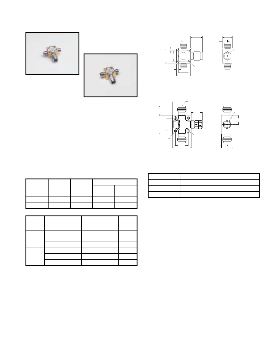
For further information about these products and more, contact us at 1-800-ANRITSU or visit www.us.anritsu.com
55
POWER SPLITTERS
K241, V241 Series, DC to 65 GHz
K241C
V241C
OUTPUT
OUTPUT
INPUT
6.1
(TYP)
2.28
2.28
14.7
14.8
(MAX)
10.16
10.16
11.5
(TYP)
K Female Connector
1/4 - 36 UNS - 2A, 2X
K Male Connector
1/2 - 36 UNS - 2B
2.64 2X
2-56 UNC-2B, 2X
4.57
9.2
Dimensions in millimeters
K241B, K241C Outline
4.6 mm
9.1 mm
2-56 UNC-2B, 2X
Ø 2.6 mm 2X
11.4 mm
6.1 mm
10.2 mm
14.7 mm
10.2 mm
14.7 mm
DC-65GHz
POWER DIVIDER
V241C
OUT
OUT
IN
7.4 mm
7.4 mm
V CONNECTOR MALE
THREAD M7.0 X .75-6H
V CONNECTOR FEMALE
THREAD M7.0 X .75-6G,2X
Dimensions in Millimeters
V241C Outline
These microwave power splitters are symmetrical, two-resistor
designs that can be used in applications where signals from DC to
65 GHz must be accurately divided for ratio measurements. They
provide excellent flatness and effective output SWR. K Connectors
®
are compatible with 3.5 mm and SMA; V Connectors
®
are
compatible with 2.4 mm.
Features
• DC to 65 GHz frequency range
• K Connector
®
compatibility with SMA/3.5 mm
• V Connector
®
compatibility with 2.4 mm
• Excellent flatness and effective output SWR
Specifications
Ordering information
Please specify model/order number, name, and quantity when ordering.
Maximum Input Power: 1W
Temperature range: 0°C to +70°C
Weight: 43g
Model/Order No.
Name
K241B
Precision Power Splitter, DC to 26.5 GHz
K241C
Precision Power Splitter, DC to 40 GHz
V241C
Precision Power Splitter, DC to 65 GHz
Model
Frequency
range (GHz)
Impedance
(Ohms)
Connectors
Input
Output
K241B
DC to 26.5
50
K(m)
K(f)
K241C
DC to 40
50
K(m)
K(f)
V241C
DC to 65
50
V(m)
V(f)
Model
Frequency
range
(GHz)
Flatness
(dB)
Input
SWR
Effective
output
SWR
Insertion
loss
(dB)
K241B
DC to 26.5
2.0
1.45
1.45
7.5
K241C
DC to 26.5
2.0
1.45
1.45
7.5
26.5 to 40
2.0
1.93
1.70
8.5
V241C
DC to 18
2.0
2.11
2.00
8.5
18 to 40
2.0
2.33
2.30
9.5
40 to 65
2.0
2.62
2.60
10.5
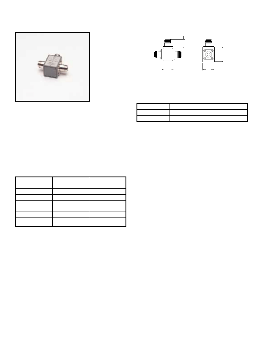
For further information about these products and more, contact us at 1-800-ANRITSU or visit www.us.anritsu.com
56
POWER SPLITTERS
N241 Series, DC to 3000 MHz
These RF power splitters are symmetrical, two resistor designs that
can be used in applications where signals from DC to 3000 MHz
must be accurately divided for ratio measurements. They are
available in 50
Ω
or 75
Ω
and provide excellent flatness and
effective output SWR.
Features
• DC to 3000 MHz frequency range
• Excellent flatness and effective output SWR
• 50
Ω
or 75
Ω
Specifications
31.8
(MAX)
31.8
(MAX)
40.64
(MAX)
17.78
(TYP.)
Dimensions in millimeters
Ordering information
Please specify model/order number, name, and quantity when ordering.
N241A50, N241A75 outline
N241A50
Maximum Input Power: 1 W
Temperature range: 0°C to +70°C
Model/Order No.
Name
N241A50
Power Splitter, DC to 3000 MHz, 50
Ω
N241A75
Power Splitter, DC to 3000 MHz, 75
Ω
Model
N241A50
N241A75
Frequency range
DC to 3000 MHz
DC to 3000 MHz
Input SWR
1.3
1.4
Effective output SWR
1.3
1.4
Insertion loss
7.5 dB
7.5 dB
Flatness
±1.5 dB
±1.5 dB
Impedance
50 Ohms
75 Ohms
Connectors
Input: N(f)
Output: N(f)
Input: N(f)
Output: N(f)
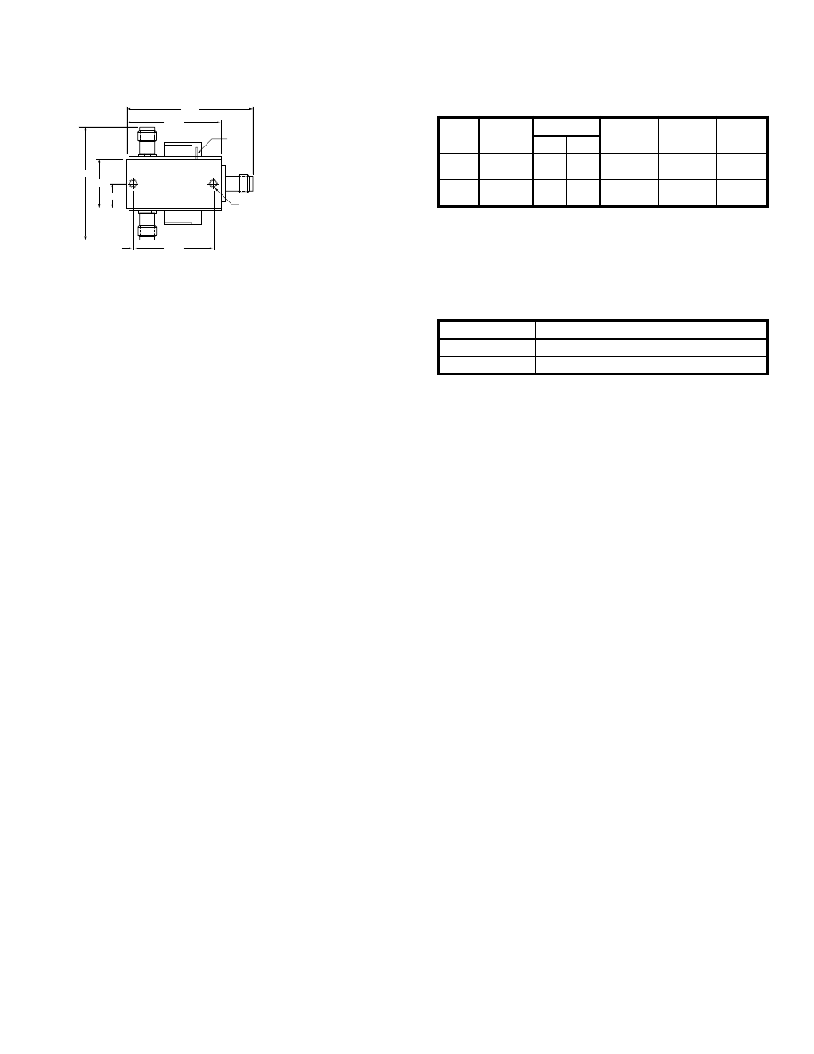
For further information about these products and more, contact us at 1-800-ANRITSU or visit www.us.anritsu.com
5
7
SPDT SWITCH
DC to 65 GHz
45.5
33.90
40.6
17.8
8.88
28.70
2.54
BIAS
2 X 4-40
UNC-2B
Dimensions in millimeters
SC4734, SC6135 outline
Coaxial 65 GHz microwave SPDT switch
Short voltage pulse driven.
Features
• Switching Speed: 20 msec max
• Operating Voltage: 20 to 30V
• Duty Cycle: 20 msec min
Ordering information
Please specify model/order number, name, and quantity when ordering.
Temperature range: 0°C to +70°C
*Call 1-800-ANRITSU for detailed information
Specifications
*
Model
Frequency
range
Connectors
Insertion
loss (dB)
Return
loss (dB)
Isolation
(dB)
in
out
SC4734
DC to 60 GHz
V(f)
V(f), V(f)
1.5
≤
40 GHz
3.0 >40 GHz
10
≤
40 GHz
6 >40 GHz
29
≤
40 GHz
26 >40 GHz
SC6135
DC to 65 GHz
V(f)
V(f), V(f)
1.5
≤
40 GHz
3.0 >40 GHz
10
≤
40 GHz
6 >40 GHz
29
≤
40 GHz
26 >40 GHz
Model/Order No.
Name
SC4734
SPDT Switch, DC to 60 GHz
SC6135
SPDT Switch, DC to 65 GHz
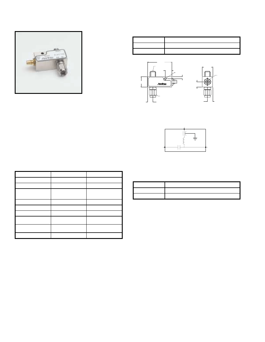
For further information about these products and more, contact us at 1-800-ANRITSU or visit www.us.anritsu.com
58
BIAS TEE
K250 100 MHz to 40 GHz, V250 100 MHz to 60 GHz
These bias tees are designed for applications where both DC and RF
signals must be applied to a device under test. They are particularly
suited for active device measurements. DC voltages of up to 30 volts
at 0.5 amps may be applied to test devices with negligible effect on
RF performance. Low RF throughline loss (<1 dB) and low return
loss ensure negligible effect on measurements up to 60 GHz. An RF
input DC block isolates the input port from the applied bias voltage.
Features
• Broadband, 0.1 to 60 GHz coverage
• Low SWR, low insertion loss
• K Connector
®
and V Connector
®
availability
Specifications
DIMENSIONS IN MILLIMETERS
6.35 NOM
Ø 2.69 THRU
12.7 NOM
6.35 NOM
12.7 NOM
2.54 NOM
7.87 NOM
29.2 NOM
6.35 NOM
OUT
BIAS TEE K250
DC
IN
RF IN
SMC MALE CONNECTOR
K FEMALE
.25-36 UNS-2A
K MALE
.25-36 UNS-2B
Outline drawing (K and V models)
DC
IN
RF
OUT
RF
IN
Schematic diagram (K and V models)
Ordering information
Please specify model/order number, name, and quantity when ordering.
Specifications
K250
1. Usable between 0.04 and 0.1 GHz with degraded performance.
Temperature range: 0°C to +70°C
Model
K250
V250
Frequency range
0.1 to 40 GHz
1
0.1 to 60 GHz
1
Insertion loss
1.2 dB typ.
2.2 dB typ.
Return loss
15 dB min. to 20 GHz
10 dB min. to 40 GHz
13 dB min. to 20 GHz
9 dB min. to 40 GHz
8 dB min. to 60 GHz
RF power
1W max.
1W max.
DC voltage
30V max.
30V max.
DC current
0.5A
0.5A
DC port isolation
20 dB at 0.1 GHz
40 dB above 0.5 GHz
20 dB at 0.1 GHz
40 dB above 0.5 GHz
RF connectors
Input: K(m)
Output: K(f)
Input: V(m)
Output: V(f)
DC connectors
SMC(m)
SMC(m)
Model/Order No.
Name
K250
Precision Bias Tee, 100 MHz to 40 GHz
V250
Precision Bias Tee, 100 MHz to 60 GHz
Temperature
0 to 60°C
Mounting position
Any
Weight
57g
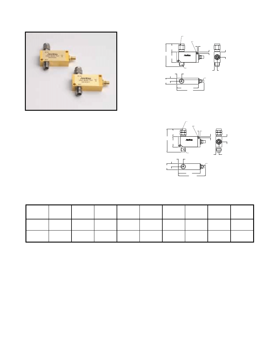
For further information about these products and more, contact us at 1-800-ANRITSU or visit www.us.anritsu.com
59
ULTRA-WIDEBAND BIAS TEES
K251 50 kHz to 40 GHz, V251 100 kHz to 65 GHz
These ultra-wide bandwidth bias tees have been optimized for
optical communications and other high-speed pulse, data or
microwave applications. Designed to simultaneously apply both
DC and RF drive signals to a device via a single input port, these
bias tees feature fast rise times, excellent low frequency response,
minimum insertion loss and flat group delay. Precision
K Connector
®
and V Connector
®
interfaces assure excellent
impedance match across the wide bandwidths available. A one year
warranty is provided. Adapters are available to convert between
K and V Connectors - See page 21 of this catalog for details.
Features
• Ideal for Optical Communications Applications
• Low Insertion Loss
• Risetime: <5 ps typical (V251), <7 ps typical (K251)
Specifications
Specifications apply over the full DC Bias current range and over the temperature range of 0°C to +70°C.
4.45
1/4-36 UNS-2B
1/4-36 UNS-2A
2.03
2.03
TYP
TYP
7.72
2X Ø.104 THRU
15.44
39.5
31.8 (MAX)
8.89
4.45
7.1
11.8
K251 BIAS TEE
RF IN
OUT
DC
IN
S/N XXXXXX
33.4
SMC MALE CONNECTOR
K MALE CONNECTOR
MOUNTING HOLE
K FEMALE CONNECTOR
Dimensions in millimeters
33.7
4.45
M7.0 X .75-6H
M7.0 X .75-6G
2.03
2.03
TYP
TYP
7.72
2X Ø.104 THRU
15.44
39.5
31.75
8.89
4.45
7.11
11.0
V251 BIAS TEE
RF IN
OUT
DC
IN
S/N XXXXXX
SMC MALE CONNECTOR
V MALE CONNECTOR
MOUNTING HOLE
V FEMALE CONNECTOR
Dimensions in millimeters
K251 outline drawing
V251 outline drawing
K251
V251
Model
Frequency
range
3dB BW
Insertion loss
Return loss
Rise time
Group delay
Max
DC current
Max
DC voltage
Max
RF power
Connectors
K251
50 kHz to
40 GHz
<2 dB typical
See Plot
< 7 ps typical
110 ± 2 ps
typical
100 mA
16VDC
1 W
RF In: K(m)
RF Out: K(f)
Bias: SMC(m)
V251
100 kHz to
65 GHz
< 2.5 dB typical
See Plot
< 5 ps typical
113 ± 2 ps
typical
100 mA
16VDC
1 W
RF In: V(m)
RF Out: V(f)
Bias: SMC(m)
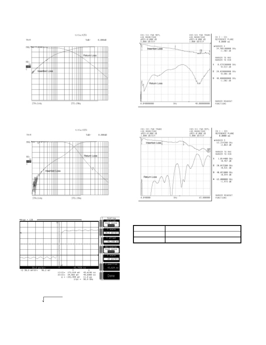
For further information about these products and more, contact us at 1-800-ANRITSU or visit www.us.anritsu.com
60
ULTRA-WIDEBAND BIAS TEES
K251 50 kHz to 40 GHz, V251 100 kHz to 65 GHz
Ordering information
Please specify model/order number, name, and quantity when ordering.
Typical Low Frequency Insertion Loss measured on V251
over the range of 1 kHz to 1 MHz.
Insertion Loss and Return Loss measured on V251 over the range
of 40 MHz to 65 GHz.
Typical Uncorrected Pulse Response for V251. Absolute risetime for the Bias
Tee is derived from this measured data by applying the RSS method to
compensate for the risetime of the input pulse.
T meas. = uncorrected risetime
T
BT
= absolute Bias Tee risetime
T
PG
= risetime of input pulse
T
BT
2
+ T
PG
2
= T meas.
Typical Low Frequency Insertion Loss and Return Loss
measured on K251 over the range of 1kHz to 1 MHz.
Typical Frequency Insertion Loss and Return Loss
measured on K251 over the range of 40 MHz to 40 GHz.
Model/Order No.
Name
K251
Precision Bias Tee, 50 kHz to 40 GHz
V251
Precision Bias Tee, 100 kHz to 65 GHz
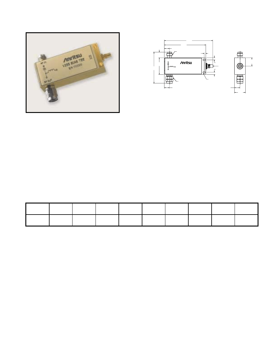
For further information about these products and more, contact us at 1-800-ANRITSU or visit www.us.anritsu.com
61
ULTRA-WIDEBAND BIAS TEES
V255 50 kHz to 65 GHz
S/N 110020
V255 BIAS TEE
RF OUT
RF IN
DC
IN
7.1
21.3
39.6
2.0
2.8
2.8
6.5
52.8
61.7
6.5
7.0
14.0
10.7
V-MALE CONNECTOR
M7.0 X 75-6H
V-FEMALE CONNECTOR
M7.0 X 75-6G
2X MOUNTING HOLE
∅
2.5[.10] THRU
SMC MALE
CONNECTOR
V255 outline drawing
K255
The V255 Gen II Ultra Wideband Bias Tee is designed to meet the
high electrical performance requirement of passive components in
optical communication networks. Given a broader bandwidth of
50 kHz to 65 GHz, with low insertion losses and very good return
loss, makes it ideal to use in 40 Gbps systems to bias optical
modulators and broad band data drivers. It's fast rise time and flat
group delay performance allows extremely accurate measurements
within a laboratory environment. The V255 Bias Tee comes with a
standard V Connector
®
that assures excellent impedance match
across the available wide bandwidth. The DC signal can be
applied or extracted from the bias tee through an SMC connector
at the third port. As with our other bias tees, the V255 also has a
one-year warranty.
Specifications
Features
• Ideal for Optical Communication applications.
• Very low Insertion Loss
• Rise Time 3 ps typical
• High Current Capacity
• High Isolation between Input Port and DC Port
Model
Frequency
range
Insertion loss
Return loss
Rise time
Group delay
Max
DC current
Max
DC voltage
Min.
Isolation
Operating
temperature
V255
50 kHz to 65 GHz
30 kHz to 65 GHz
typical
1.2 dB to 65 GHz
typical
<–15 dB to 65 GHz
typical
3 ps typical
125 ± 2 ps typical
400 mA
16 VDC
–50 dBm
0˚C to 80˚C
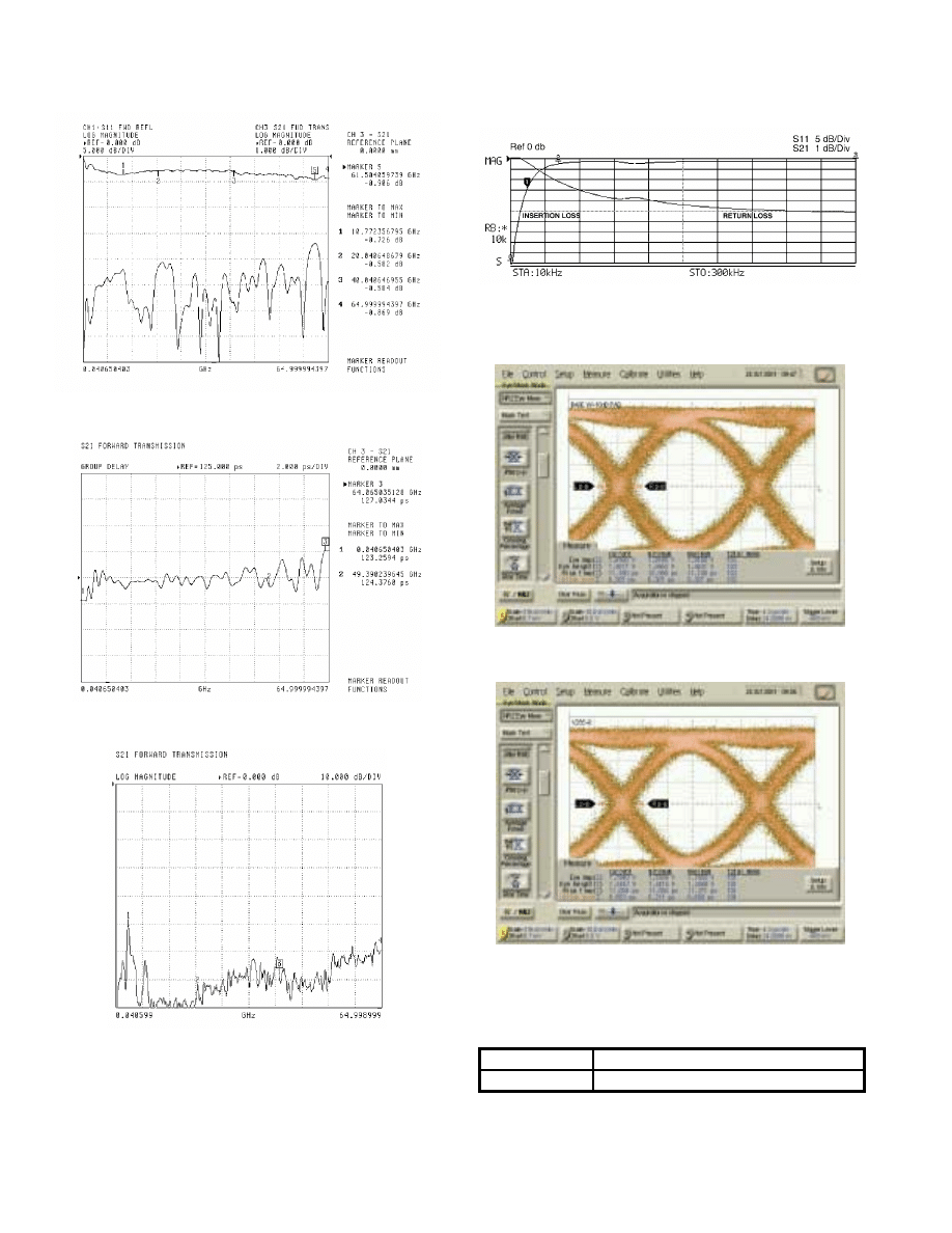
For further information about these products and more, contact us at 1-800-ANRITSU or visit www.us.anritsu.com
62
ULTRA-WIDEBAND BIAS TEES
V255 50 kHz to 65 GHz
Typical Group Delay Performance measured on V255 using
Anritsu 37397C VNA
Typical High Frequency Insertion Loss and Return Loss measured on V255
over the range of 40 MHz to 65 GHz using Anritsu 37397C VNA
Typical Isolation between Data I/P and DC Port using
Anritsu 37397C VNA
Typical Low Frequency Insertion Loss and Return Loss
measured on V255 Bias Tee over the range of 10 kHz to 300 kHz
Ordering information
Please specify model/order number, name, and quantity when ordering.
Model/Order No.
Name
V255
Gen II Wideband Bias Tee, 50 kHz to 65 GHz
Input Test Signal to V255 2.0 V NRZ Input Signal using
Anritsu 43G ME7750A BERT
V255 Output Response to 2.0V NRZ Input Signal using
Anritsu 43G ME7750A BERT
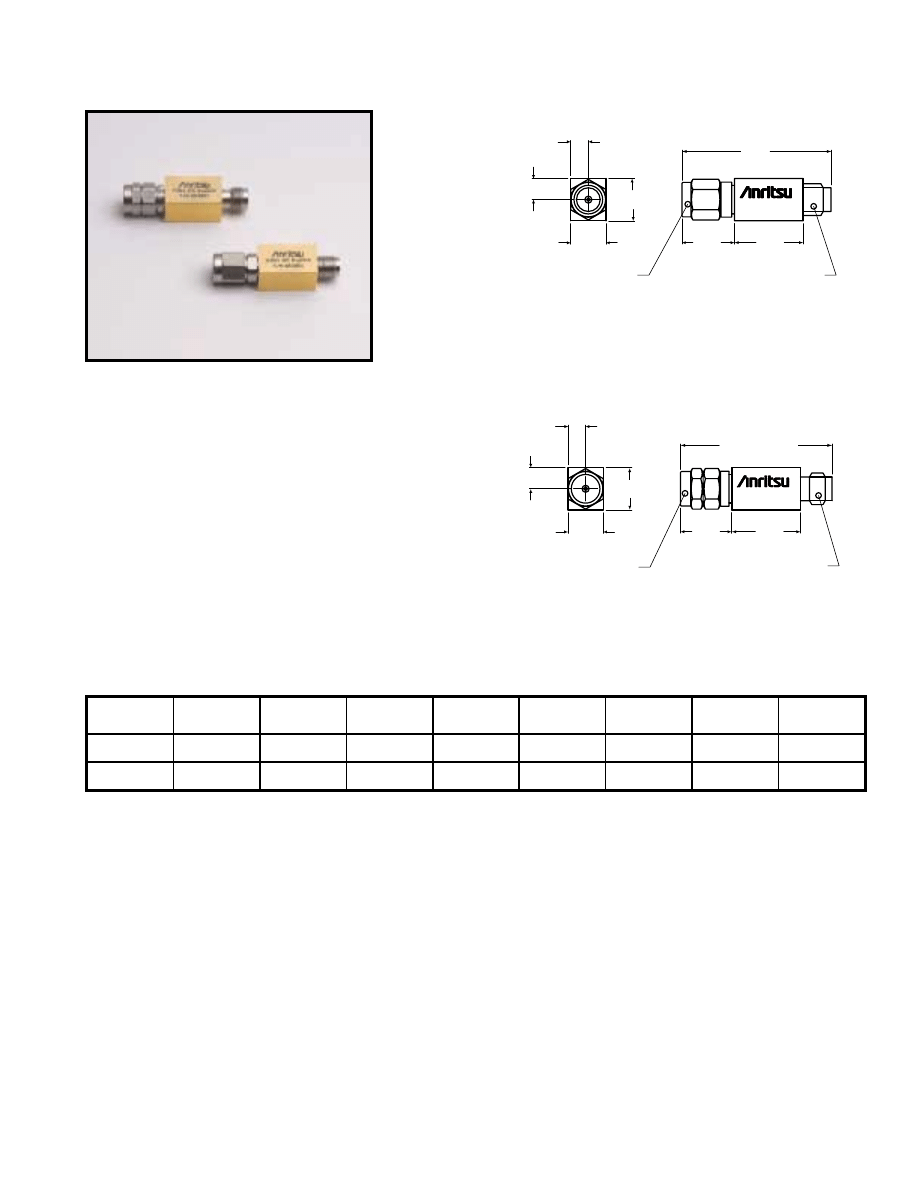
For further information about these products and more, contact us at 1-800-ANRITSU or visit www.us.anritsu.com
63
PRECISION DC BLOCKS
K261, 10 kHz to 40 GHz, V261 50 kHz to 65 GHz
3.96
15.44
9.53
4.78
7.92
K261
1/4-36 UNS-2B
1/4-36 UNS-2A
11.8
33.5
K MALE CONNECTOR
K FEMALE CONNECTOR
Dimensions in millimeters
3.96
34.0
15.44
11.5
9.53
4.78
7.92
V261
M7.0 X .75-6H
M7.0 X .75-6G
V MALE CONNECTOR
V FEMALE CONNECTOR
Dimensions in millimeters
K261 outline drawing
V261 outline drawing
These ultra-wide bandwidth DC Blocks have been optimized
for optical communications and other high-speed pulse, data or
microwave applications. Designed to apply AC drive signals to a
device while eliminating any DC components, these DC Blocks
feature wide bandwidth, excellent low frequency response,
minimum insertion loss and flat group delay. Precision
K Connector
®
and V Connector
®
interfaces assure excellent
impedance match across the wide bandwidths available. A one
year warranty is provided.
Features
• Ideal for Optical Communications and
high speed Pulse Applications
• <1.0 dB Insertion Loss (K261)
• Risetime: <5 ps (V261), <7 ps (K261)
Specifications
V261
K261
Specifications apply over the temperature range of 0°C to +70°C.
Model
Frequency range
3 dB BW
Insertion loss
Return loss
Rise time
Group delay
Max
DC voltage
Max
RF power
Connectors
K261
10 kHz to
40 GHz
<1.0 dB typical
See Plot
< 7 ps typical
110 ±1 ps typical
16VDC
1 W
RF In: K(m)
RF Out: K(f)
V261
50 kHz to
65 GHz
< 2.0 dB typical
See Plot
< 5 ps typical
113 ±1 ps typical
16VDC
1 W
RF In: V(m)
RF Out: V(f)
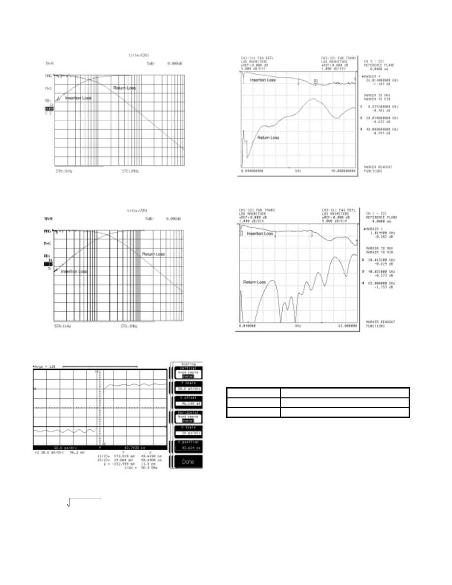
For further information about these products and more, contact us at 1-800-ANRITSU or visit www.us.anritsu.com
64
PRECISION DC BLOCKS
K261, 10 kHz to 40 GHz, V261 50 kHz to 65 GHz
Typical Low Frequency Insertion Loss measured on V261 over
the range of 1 kHz to 1 MHz.
Insertion Loss and Return Loss measured on V261 over the range
of 40 MHz to 65 GHz.
Typical Uncorrected Pulse Response for V261. Absolute risetime for the DC
Blocks is derived from this measured data by applying the RSS method to
compensate for the risetime of the input pulse.
T meas. = uncorrected risetime
T
BT
= absolute Bias Tee risetime
T
PG
= risetime of input pulse
T
BT
2
+ T
PG
2
= T meas.
Ordering information
Please specify model/order number, name, and quantity when ordering.
Typical Low Frequency Insertion Loss measured on K261 over
the range of 1 kHz to 1 MHz.
Insertion Loss and Return Loss measured on K261 over the range
of 40 MHz to 40 GHz.
Model/Order No.
Name
K261
Precision DC Block, 50 kHz to 40 GHz
V261
Precision DC Block, 100 kHz to 65 GHz
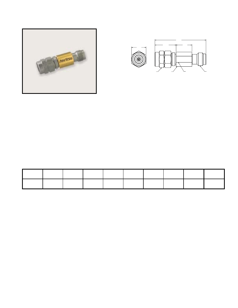
For further information about these products and more, contact us at 1-800-ANRITSU or visit www.us.anritsu.com
65
DC BLOCKS
V265, 50 kHz to 65 GHz
V265 outline drawing
The V265 DC Block has been designed and optimized for optical
communications and other high speed pulse, data or microwave
applications. Based on the coaxial resilient connection – which is
the same as on our V255 Gen II Bias Tee – it provides excellent low
frequency response with very low losses and flat group delay over
the temperature of operation. Designed to apply AC drive signals to
a device while eliminating any DC voltage or current components,
the V265 DC Block can be used in isolating DC leakage between
two electrical components. The DC block comes with a standard
V Connector
®
and assures excellent impedance match across the
wide bandwidth available. A one-year warranty is provided.
Specifications
Features
• Ideal for Optical Communication applications.
• Low Insertion Loss
• Rise Time 3 ps typical
V265
Model
Frequency
range
Insertion loss
Return loss
Rise time
Group delay
Max
DC voltage
Max
RF power
Connectors
Operating
temperature
V265
50 kHz to 65 GHz
30 kHz to 65 GHz
typical
<0.7 dB to 65 GHz
typical
<–15 dB to 65 GHz
typical
3 ps typical
84 ±2 ps typical
16 VDC
1 W
RF In: V(f)
RF Out: V(m)
0˚C to 80˚C
V265
11.5
8.6
27.8
V MALE CONNECTOR
M7.0 X .75-6H
V FEMALE
CONNECTOR
M7.0 X .75-6G
7.1
ACROSS FLATS
7.9
7.9
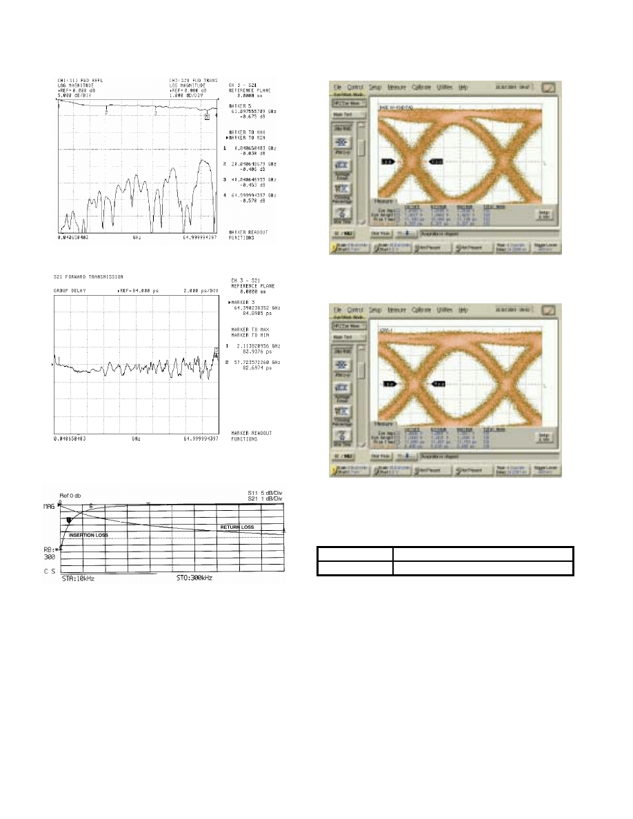
For further information about these products and more, contact us at 1-800-ANRITSU or visit www.us.anritsu.com
66
PRECISION DC BLOCKS
V265, 50 kHz to 65 GHz
Typical Low Frequency Insertion Loss and Return Loss measured on V265 Bias
Tee over the range of 10 kHz to 300 kHz using
Anritsu MS4630B Network Analyzer
Ordering information
Please specify model/order number, name, and quantity when ordering.
Typical High Frequency Insertion Loss and Return Loss measured on V265
over the range of 40 MHz to 65GHz using Anritsu 37397C VNA
Typical Group Delay Performance measured on V265 using
Anritsu 37397C VNA
Input Test Signal to V265 2.0 V NRZ Input Signal using
Anritsu 43G ME7750A BERT
V265 Output Response to 2.0V NRZ Input Signal using
Anritsu 43G ME7750A BERT
Model/Order No.
Name
V265
DC Block, 50 kHz to 65 GHz
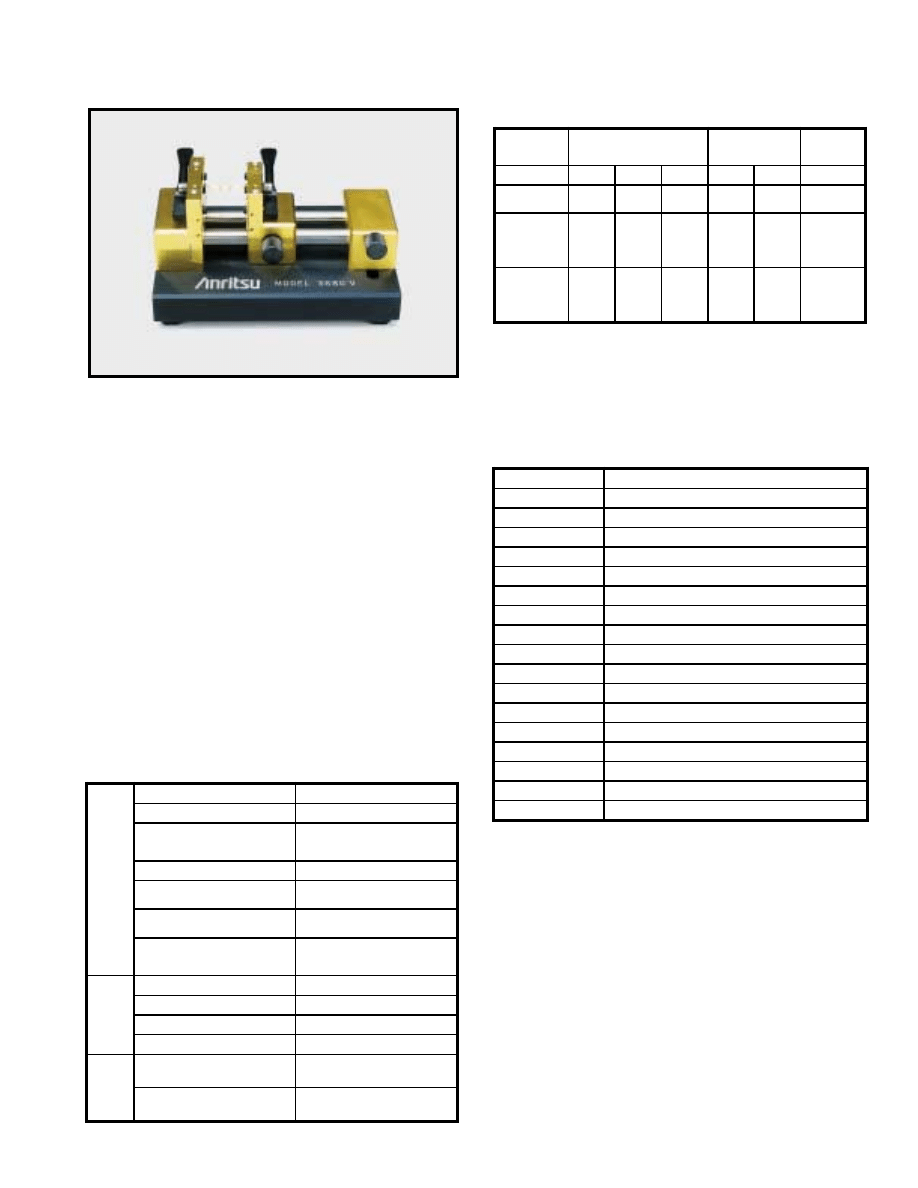
For further information about these products and more, contact us at 1-800-ANRITSU or visit www.us.anritsu.com
67
UNIVERSAL TEST FIXTURES
3680 Series DC to 60 GHz
The 3680 series provide an accurate, repeatable solution for
measuring microstrip and Coplanar substrate devices. Input and
output connections are made to the substrate device by two spring-
loaded jaws that include coax-to-microstrip/Coplanar launchers.
The jaws accommodate substrates from 0.13 to 1.9 mm in thickness.
No center section is required. One jaw is movable in two dimensions
to accommodate substrates up to 50 mm long (100 mm for 3680-20)
and substrates with line offsets of up to 12.7 mm (25 mm for
3680-20). The 3680 series includes three models: the 3680-20
covers DC to 20 GHz with APC-3.5
™
connectors, the 3680K covers
DC to 40 GHz with Anritsu's K Connector
®
, and the 3680V
covers DC to 60 GHz with Anritsu's V Connector
®
.
Features
• DC to 60 GHz coverage
• Microstrip and coplanar measurement capability
• Accommodates offset and right-angle test devices
• Calibration/verification kits (optional)
• Substrate measurement capability
Specifications
Electrical
Ordering information
Please specify model/order number, name and quantity when ordering.
1. 36805 series includes (4) substrate launchers for the 36802 MMIC attachment
Temperature range: –20° to 70°C
3680 series Universal T
est Fixture
Substrate types supported
Microstrip or coplanar waveguide
Overall size
10 x 12.7 x 6.4 cm
Substrate length
0.5 cm min.
5 cm max.
[10 cm with 3680-20]
Maximum substrate width
No limit
Substrate thickness
0.012 cm min.
0.19 cm max.
Maximum line offset
±1.2 cm
[±2.5 cm with 3680-20]
Input and output connectors
3680-20: APC-3.5™ female
3680K: K Connector
®
female
3680V: V Connector
®
female
36802 MMIC
Attachment
Substrate thickness
0.0 cm, 0.038 cm, 0.064 cm
Minimum test substrate length
1.5 mm
Maximum test substrate length
1.17 cm with standard block
Maximum line offset
±1.2 cm
36801 Right
Angle
Launcher
Distance from in-line connector, axial
Minimum: 1 cm
Maximum: 4 cm
Distance from in-line connector, offset
Minimum: 0.0 cm
Maximum: 2 cm
Model
Universal
Test Fixture
Right-Angle
Launcher
MMIC
Attachment
3680-20 3680K
3680V
36801K 36801V
36802
Frequency
range (GHz)
DC to 20
DC to 40
DC to 60
DC to 40
DC to 60
DC to 60
Return loss (dB)
DC to 20 GHz
20 to 40 GHz
40 to 60 GHz
>17
>17
>14
>17
>14
>8
>16
>12
>16
>12
>7
>12
>8
>6
Repeatability (dB)
DC to 20 GHz
20 to 40 GHz
40 to 60 GHz
<±
0.10
<±0.10
<±0.20
<±0.10
<±0.20
<±0.30
<±0.15
<±0.25
<±0.15
<±0.25
<±0.40
<±0.20
<±0.40
<±0.60
Model/Order No.
Name
Main frame
3680-20
Universal Test Fixture (20 GHz)
3680K
Universal Test Fixture (40 GHz)
3680V
Universal Test Fixture (60 GHz)
Accessories
36801K
Right-Angle Launcher (40 GHz)
36801V
Right-Angle Launcher (60 GHz)
36802
MMIC Attachment
36803
Bias Probe
36805-10M
10 mil launchers
1
36805-15M
15 mil launchers
1
36805-25M
25 mil launchers
1
Calibration/verification kits
36804B-10M
10 mil microstrip cal/verif. kit, DC to 60 GHz
36804B-15M
15 mil microstrip cal/verif. kit, DC to 30 GHz
36804B-25M
25 mil microstrip cal/verif. kit, DC to 20 GHz
36804B-25C
25 mil coplanar waveguide cal/verif. kit, DC to 20 GHz
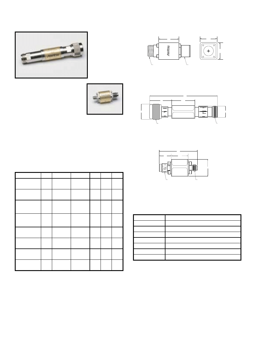
For further information about these products and more, contact us at 1-800-ANRITSU or visit www.us.anritsu.com
68
LIMITERS
1 Series 1 MHz to 26.5 GHz
Broadband microwave limiter features
• High power protection: Up to 5 Watts
• Very fast turn-on time: 10 ns max.
• Broad frequency range: 0.01 to 26.5 GHz
• Low insertion loss: 2.7 dB to 20 GHz
• Excellent return loss: 11 dB at 20 GHz
• Single side limiting
Specifications
1N50C
1K50B
Dimensions in millimeters
30
25
25
N Connector Male
N Connector Female
L
IM
IT
E
R
S
M
O
D
E
L
1
N
7
5
B
FREQ
UENCY RANGE
1MHz - 3000 MHz
MAXIMUM
INPUTS
RF LIMITERS
N Connector Male
N Connector Female
95
32.3
13
21 Dia.
15.7 Dia.
Dimensions in millimeters
MAXIMUM
INPUTS
RF LIMITERS
17.4
13
40
17.4 Dia.
K Connector Male
K Connector Female
Dimensions in millimeters
1N50C and 1N75C Limiters Outline
1K50A and 1K50B Limiters Outline
1N50B and 1N75B Limiters Outline
Limiting Level: Limiter begins compressing at approximately +10 dBm. In
compression, output level increases by 0.25 to 0.5 dB for each 1 dB increase at the
input. Output power at 5W input at 500 MHz is 21 dBm max.
Dimensions: 1N50B and 1N75B 3.8 cm x 2.5 cm x 2.5 cm
Temperature range: 0°C to +70°C
Ordering information
Please specify model/order number, name and quantity when ordering.
Model/Order No.
Name
Limiter
1N50B
N(m) to N(f), 50
Ω
, 1 MHz to 3 GHz
1N75B
N(m) to N(f), 75
Ω
, 1 MHz to 3 GHz
1N50C
N(m) to N(f), 50
Ω
, 10 MHz to 20 GHz
1N75C
N(m) to N(f), 75
Ω
, 10 MHz to 3 GHz
1K50A
K(m) to K(f), 50
Ω
, 10 MHz to 20 GHz
1K50B
K(m) to K(f), 50
Ω
, 10 MHz to 26.5 GHz
Model
1K50B
1K50A
1N50C
1N75C
1N50B
1N75B
Frequency
range
0.01 to
26.5 GHz
0.01 to
20 GHz
0.01 to
18 GHz
0.01 to
3 GHz
0.01 to
3 GHz
0.01 to
3 GHz
Max.
input power
3
Watts
5
Watts
5
Watts
5
Watts
1.5
Watts
1.5
Watts
Min.
return loss
(at 0 dBm input)
10 dB
14 dB,
≤
12 GHz
11 dB, >12 GHz
14 dB,
≤
12 GHz
11 dB, >12 GHz
15 dB
19 dB
19 dB
Max.
insertion loss
(at 0 dBm input)
3.9 dB
2.7 dB
2.9 dB
1.1 dB
1.3 dB
1.3 dB
Max.
turn-on time
10 ns
10 ns
10 ns
10 ns
10 ns
10 ns
Input
connector
K(m)
K(m)
N(m)
75
Ω
N(m)
N(m)
75
Ω
N(m)
Output
connector
K(f)
K(f)
N(f)
75
Ω
N(f)
N(f)
75
Ω
N(f)
Input/output
coupling
DC
DC
DC
DC
AC
AC
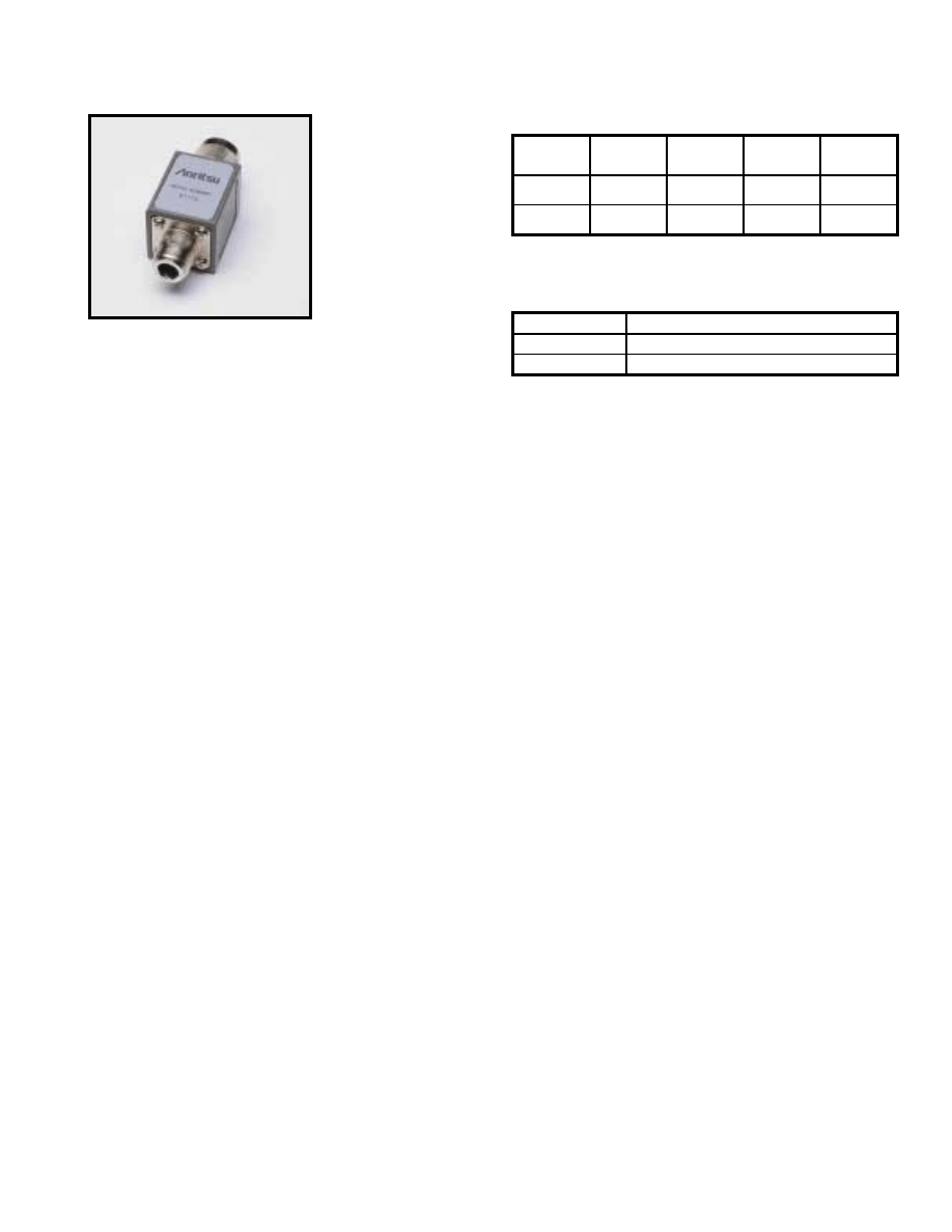
For further information about these products and more, contact us at 1-800-ANRITSU or visit www.us.anritsu.com
69
MATCHING PADS
12 Series DC to 3000 MHz
Specifications
RF matching pad and impedance
adapter features
• DC to 3000 MHz frequency range
• Matching pad matches 50
Ω
to 75
Ω
or 75
Ω
to 50
Ω
circuits
• Impedance adapter converts 50
Ω
to 75
Ω
with <3 dB loss
The 12N50-75B matching pad is a two-resistor design that matches
50
Ω
to 75
Ω
or 75
Ω
to 50
Ω
circuits.
The 12N75B impedance adapter is a one-resistor design that
converts 50
Ω
to 75
Ω
with less than 3 dB loss.
12N50-75B
Temperature range: 0°C to +70°C
Dimensions: 3.8 cm x 2.5 cm x 2.5 cm
Ordering information
Please specify model/order number, name and quantity when ordering.
Model
Frequency
range (MHz)
SWR
Insertion loss
(dB)
Connectors
12N50-75B
DC to 3000
1.25
7.5 max.
N(m) 50
Ω
to
N(f) 75
Ω
12N75B
DC to 3000
1.25
3.0 max.
N(m) 50
Ω
to
N(m) 75
Ω
Model/Order No.
Name
12N50-75B
Matching Pad, DC to 3000 MHz
12N75B
Minimum Loss Adapter, DC to 3000 MHz
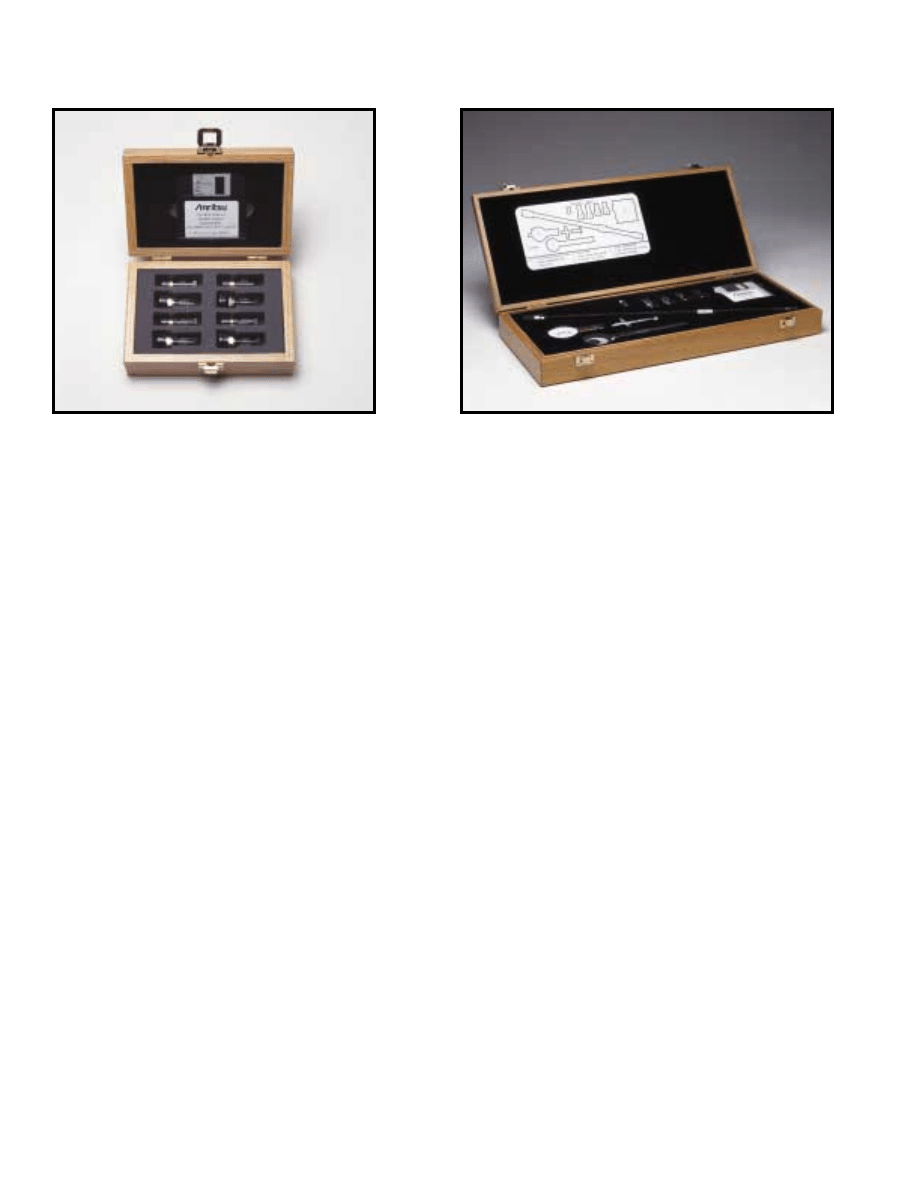
For further information about these products and more, contact us at 1-800-ANRITSU or visit www.us.anritsu.com
70
VNA AND VNMS CALIBRATION KITS
3753LF
3651, Option 1
The Anritsu Calibration Kits contain all the precision components
and tools required to calibrate your VNA or VNMS for 12-term
error-corrected measurements in the connector style of your choice.
Components are included for calibrating male and female test ports
as required. The kits support calibration with opens, shorts, and
broadband loads. Option 1 adds sliding terminations and a pin depth
gauge where required.
The following kits are for use with 37XXX Lightning VNAs.
3650 SMA/3.5 mm Calibration Kit consisting of:
• 34ASF50-2 Female Adapter (2)
• 33KFKF50 Female-Female Adapter (2)*
• 33SS50 Male-Male Adapter*
• 28S50-2 B Male Termination (2)
• 28SF50-2 Broadband Female Termination (2)
• 33SSF50-Male-Female Adapter (2)*
• 24S50 Male Open
• 23SF50 Female Open
• 23S50 Male Short
• 23SF50 Female Short
• 34AS50-2 Male Adapter (2)
• Connector Thumb Wheel (4)
• 01-201 Torque Wrench
• 01-210 Reference Flat
• 01-222 Pin Depth Gauge
• 01-223 Pin Depth Gauge
• Calibration coefficients diskette
Option 1
Adds the following:
• 01-212 Female Flush Short
• 01-211 Male Flush Short
• 17SF50 Female Sliding Termination
• 7S50 Male Sliding Termination
3651 GPC-7 Calibration Kit consisting of:
• 28A50-2 Broadband Termination (2)
• 24A50 Open
• 23A50 Short
• 01-200 Torque Wrench
• 01-221 Collet Extractor Tool and 4 Collets
• Calibration coefficients diskette
Option 1
Adds the following:
• 17A50 Sliding Termination
• 01-210 Reference Flat
• 01-220 Pin Depth Gauge
3652 K Connector
®
Calibration Kit consisting of:
• 34AKF50-2 Female Adapter (2)
• 33FKF50 Female-Female Adapter (2)*
• 33KK50 Male-Male Adapter*
• 28K50-2 Male Termination (2)
• 28KF50-2 broadband Female termination (2)
• 33KKF50-Male-Female Adapter (2)*
• 24K50 Male Open
• 23KF50 Female Open
• 23K50 Male Short
• 23KF50 Female Short
• 34AK50-2 Male Adapter (2)
• 01-201 Torque Wrench
• 01-210 Reference Flat
• 01-222 Pin Depth Gauge
• 01-223 Pin Depth Gauge
• Calibration coefficients diskette
• Connector thumb wheel (4)
Option 1
Adds the following:
• 17KF50 Female Sliding Termination
• 17K50 Male Sliding Termination
• 01-212 Female Flush Short
• 01-211 Male Flush Short
3653 Type N Calibration Kit consisting of:
• 23NF50 Female Short
• 23N50 Male Short
• 24NF50 Female Open
• 24N50 Male Open
• 28N50-2 Broadband Male Termination (2)
• 28NF50-2B Brodband Female Termination (2)
• 34AN50-2 Male Adapter (2)
• 34ANF50-2 Female Adapter (2)
• 01-213 Reference Gauge
• 01-224 Pin Depth Gauge
• Calibration coefficients diskette
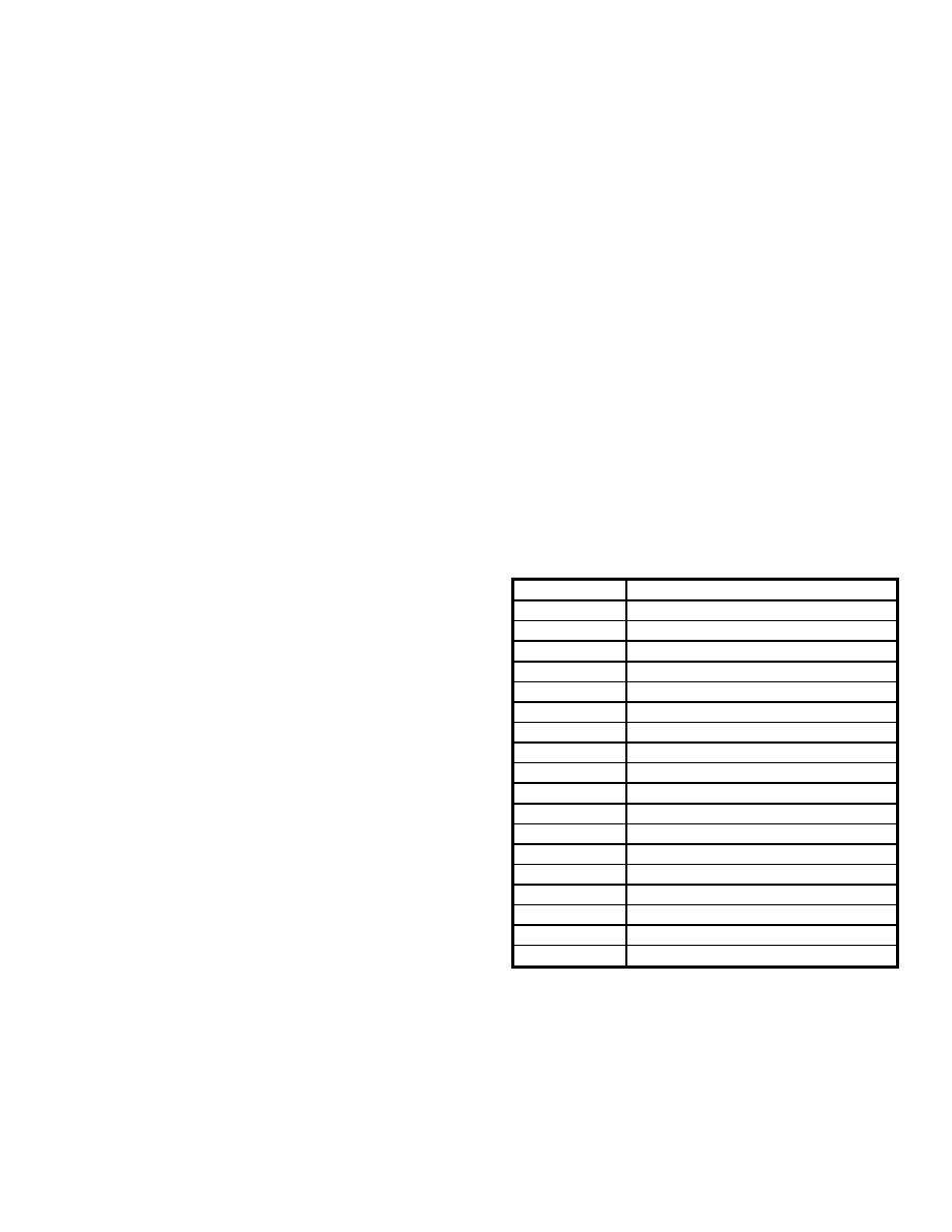
For further information about these products and more, contact us at 1-800-ANRITSU or visit www.us.anritsu.com
71
VNA AND VNMS CALIBRATION KITS
3654B V Connector
®
Calibration Kit consisting of:
• 23V50B-5.1 Male Short 5.1mm
• 23VF50B-5.1 Female Short 5.1mm
• 24V50B Male Open
• 24VF50B Female Open
• 28V50B Male Broadband Termination (2)
• 28VF50B Female Broadband Termination (2)
• 17VF50B Female Sliding Termination
• 17V50B Male Sliding Termination
• 33VV50 Male-Male Adapter*
• 33VFVF50 Female-Female Adapter (2)*
• 33VVF50 Male-Female Adapter (2)*
• Calibration coefficients diskette
• Connector thumb wheel (4)
• 01-201 Torque Wrench
• 01-210 Reference Flat
• 01-322 Pin Depth Gauge
• 01-323 Female Adapter for pin gauge
• 01-204 Adapter Wrench
• 01-312 Male Flush Short
• 01-311 Female Flush Short
3655 Waveguide Calibration Kit
The 3655 Calibration Kit contains all of the precision components
and tools required to calibrate your VNA for 12-term error-corrected
measurements of test devices with the appropriate waveguide
designation. Components are included for calibrating both module
ports. The kit supports calibration with offset shorts and broadband
loads. Option 1 adds a sliding termination.
Consisting of:
• Short, Flush (2)
• Offsets, 1/8 and 3/8 Wavelength
• Terminations, Fixed (2)
• Test Port Sections (2)
Option 1
Adds the following:
• Sliding Termination
3750 SMA/3.5 mm Calibration Kit consisting of:
• 23LF50 Female Short
• 23L50 Male Short
• 24LF50 Female Open
• 24L50 Male Open
• 28L50 Male Termination (2)
• 28LF50 Female Termination (2)
• Calibration coefficients diskette
3751 GPC-7 Calibration Kit consisting of:
• 23A50 Short
• 24A50 Open
• 28A50 Termination (2)
• Calibration coefficients diskette
Option 1
Adds the following:
• 28A50LF 3rd Termination
3753 Type N Calibration Kit consisting of:
• 23NF50 Female Short
• 24NF50 Female Open
• 24N50 Male Open
• 28NF50 Female Termination (2)
• 28N50 Male Termination (2)
• 23N50 Male Short
• Calibration coefficients diskette
The following kits are for use with MS462XX Scorpion VNAs.
3750LF SMA/3.5 mm 6 GHz Calibration Kit consisting of:
• 23LF50 Female Short
• 23L50 Male Short
• 24LF50 Female Open
• 24L50 Male Open
• 28L50LF Male Termination (2)
• 28LF50LF Female Termination (2)
• Calibration coefficients diskette
3751LF GPC-7 6 GHz Calibration Kit consisting of:
• 23A50 Short
• 24A50 Open
• 28A50LF Termination (2)
• Calibration coefficients diskette
Option 1
Adds the following:
• 28A50LF 3rd Termination
3753LF Type N 6 GHz Calibration Kit consisting of:
• 23NF50 Female Short
• 24NF50 Female Open
• 24N50 Male Open
• 28NF50LF Female Termination (2)
• 28N50LF Male Termination (2)
• 23N50 Male Short
• Calibration coefficients diskette
Ordering information
Please specify model/order number, name and quantity when ordering.
* Phase Equal Adapters
Model/Order No.
Name
Calibration kits
3650
SMA/3.5 mm calibration kit
Option 1
Adds sliding terminations
3651
GPC-7 calibration kit
Option 1
Adds sliding terminations
3652
K Connector
®
calibration kit
Option 1
Adds sliding terminations
3653
Type N calibration kit
3654B
V Connector
®
calibration kit with sliding terminations
3655
Waveguide calibration kit
Option 1
Adds sliding terminations
3750
SMA/3.5 mm 8.6 GHz calibration kit
3750LF
SMA/3.5 mm 6 GHz calibration kit
3751
GPC-7 8.6 GHz calibration kit
3751LF
GPC-7 6 GHz calibration kit
3753
Type N 8.6 GHz calibration kit
3753LF
Type N 6 GHz calibration kit
3753-75
75 Ohm Type N 3 GHz calibration kit
For further information about these products and more, contact us at 1-800-ANRITSU or visit www.us.anritsu.com
72
VNA AND VNMS VERIFICATION KITS
The Anritsu Verification Kits contain precision components
with characteristics that are traceable to NIST. Used primarily by the
metrology laboratory, these components provide the most dependable
means of determining the system accuracy of your VNA. A disk
containing factory measured test data for all components is supplied
for comparison with customer-measured data.
The following kits are for use with 37XXX Lightning VNAs.
3663 Type N Verification Kit consisting of:
• 42N-50, 50 dB Attenuator
• 18N50-10, 10 cm Airline
• 42N20, 20 dB Attenuator
• 18N50-10B, 10 cm Stepped Impedance Airline (Beatty standard)
• Verification kit disks
3665 Waveguide Verification Kit consisting of:
• Straight section
• Pin set
• Mismatch section
• Ball driver
• 50 dB Attenuator
• 20 dB Attenuator
• Verification kit disks
3666 SMA/3.5 mm Verification Kit consisting of:
• 19S50-7, 7.5 cm Airline
• 19SF50-7B, 7.5 cm Stepped Impedance Airline (Beatty standard)
• 42S-50, 50 dB Attenuator
• 42S-20, 20 dB Attenuator
• Verification kit disks
3667 GPC-7 Verification Kit consisting of:
• 42A-50, 50 dB Attenuator
• 18A50-10, 10 cm Air line
• 42A-20, 20 dB Attenuator
• 18A50-10B, 10 cm Stepped Impedance Airline (Beatty standard)
• Verification kit disks
3668 K Connector
®
Verification Kit consisting of:
• 19K50-7, 7.5 cm Airline
• 42K-50, 50 dB Attenuator
• 42K-20, 20 dB Attenuator
• 18K50-7B, 7.5 cm Stepped Impedance Airline (Beatty standard)
• Verification kit disks
3669B V Connector
®
Verification Kit consisting of:
• 42V-40, 40 dB Attenuator
• 42V-20, 20 dB Attenuator
• 19V50-5, 5 cm Airline
• 18V50-5B, 5 cm Stepped Impedance Airline (Beatty standard)
• Verification kit disks
The following kits are for use with MS462XX Scorpion VNAs.
3663LF Type N 6 GHz Verification Kit consisting of:
• 42N-50, 50 dB Attenuator
• 42N20, 20 dB Attenuator
• 42NOP-20 N Mismatch attenuator
• Verification kit disks
3666LF SMA/3.5 mm 6 GHz Verification Kit consisting of:
• 42L-50, 50 dB Attenuator
• 42L-20, 20 dB Attenuator
• 42LOP-20 SMA/3.5 mm Mismatch Attenuator
• Verification kit disks
3667LF GPC-7 6 GHz Verification Kit consisting of:
• 42A-50, 50 dB Attenuator
• 42A-20, 20 dB Attenuator
• 42AOP-20 GPC-7 Mismatch Attenuator
• Verification kit disks
Ordering information
Please specify model/order number, name and quantity when ordering.
3669B
Model/Order No.
Name
Verification kits
3663
Type N verification kit
3665
Waveguide verification kit
3666
SMA/3.5 mm verification kit
3667
GPC-7 verification kit
3668
K Connector
®
verification kit
3669B
V Connector
®
verification kit
3663LF
Type N 6 GHz verification kit
3666LF
SMA/3.5 mm 6 GHz verification kit
3667LF
GPC-7 6 GHz verification kit

For further information about these products and more, contact us at 1-800-ANRITSU or visit www.us.anritsu.com
73
PART NUMBER INDEX
01-101A
K Connector Evaluation Kit . . . . . . . . . . . . . . . . . . . . . . . . . . . . . . . . 6
01-103
Soldering Fixture for sparkplug launcher glass beads,
package of 10 . . . . . . . . . . . . . . . . . . . . . . . . . . . . . . . . . . . . . . . . . . . . 6
01-104
Drill and Tap Set for K Connectors . . . . . . . . . . . . . . . . . . . . . . . . . . . 6
01-105A
Male and Female Sparkplug Torquing Kit . . . . . . . . . . . . . . . . . . 6,11
01-106
K Soldering Fixture for flange launcher glass bead,
package of 5 . . . . . . . . . . . . . . . . . . . . . . . . . . . . . . . . . . . . . . . . . . . . . 6
01-107F
Cable Sleeve Soldering Fixture for
K101F Female Cable Connectors, package of 10 . . . . . . . . . . . . . . . 6
01-107M
Cable Sleeve Soldering Fixture for
K101M Male Cable Connectors, package of 10 . . . . . . . . . . . . . . . . 6
01-108
Drill and Tap Set for K Connector with Sliding Contacts . . . . . . . . . 6
01-118
K Connector Cable Assembling Fixture Kit for
K 118 semi-rigid coaxial cable . . . . . . . . . . . . . . . . . . . . . . . . . . . . . . 6
01-201
Torque wrench for SMA, 3.5 mm and K Connectors . . . . . . . . . . . 14
01-204
Handy wrench for SMA, 3.5 mm, K, 2.4 mm
and V Connectors . . . . . . . . . . . . . . . . . . . . . . . . . . . . . . . . . . . . . . . . 14
01-301
V Connector Evaluation Kit . . . . . . . . . . . . . . . . . . . . . . . . . . . . . . . 10
01-303
Soldering Fixture for V sparkplug launcher glass beads,
package of 10 . . . . . . . . . . . . . . . . . . . . . . . . . . . . . . . . . . . . . 10
01-304
Drill and Tap Set for V connectors . . . . . . . . . . . . . . . . . . . . . . . . . . 10
01-306
Soldering fixture for flange launcher glass bead . . . . . . . . . . . . . . . 11
01-307M
Cable sleeve soldering fixture, male connector . . . . . . . . . . . . . . . . 11
01-307F
Cable sleeve soldering fixture, female connector . . . . . . . . . . . . . . . 11
01-308
Drill and Tap set . . . . . . . . . . . . . . . . . . . . . . . . . . . . . . . . . . . . . . . . . 11
01-309
V Connector Cable Assembling Fixture Kit . . . . . . . . . . . . . . . . . . 11
01-501
Bullet Insertion and Removal Tool . . . . . . . . . . . . . . . . . . . . . . . . . . 15
01-502
Torque Screwdriver Adapter . . . . . . . . . . . . . . . . . . . . . . . . . . . . . . . 15
10-75
Diode Module, 75A50 . . . . . . . . . . . . . . . . . . . . . . . . . . . . . . . . . . . . 48
10-108
Diode Module, 71 & 73 Series . . . . . . . . . . . . . . . . . . . . . . . . . . . . . 48
11N50B
RF Power Divider, N . . . . . . . . . . . . . . . . . . . . . . . . . . . . . . . . . . . . . 53
11N75B
RF Power Divider, 75
Ω
N . . . . . . . . . . . . . . . . . . . . . . . . . . . . . . . . 53
12N50-75B
Matching Pad, N(m) 50
Ω
to N(f) 75
Ω
. . . . . . . . . . . . . . . . . . . . . . 69
12N75B
Impedance Adapter, N(m) 50
Ω
to N(f) 75
Ω
. . . . . . . . . . . . . . . . . 69
18A50
Air Line, GPC-7 . . . . . . . . . . . . . . . . . . . . . . . . . . . . . . . . . . . . . . . . . 43
18N50
Air Line, N(m) . . . . . . . . . . . . . . . . . . . . . . . . . . . . . . . . . . . . . . . . . . 43
18NF50
Air Line, N(f) . . . . . . . . . . . . . . . . . . . . . . . . . . . . . . . . . . . . . . . . . . . 43
19K50
Air Line, K(m) . . . . . . . . . . . . . . . . . . . . . . . . . . . . . . . . . . . . . . . . . . 43
19KF50
Air Line, K(f) . . . . . . . . . . . . . . . . . . . . . . . . . . . . . . . . . . . . . . . . . . . 43
19S50
Air Line, WSMA(m) . . . . . . . . . . . . . . . . . . . . . . . . . . . . . . . . . . . . . 43
19SF50
Air Line, WSMA(f) . . . . . . . . . . . . . . . . . . . . . . . . . . . . . . . . . . . . . . 43
1K50A
Limiter, K, 0.01 to 20 GHz . . . . . . . . . . . . . . . . . . . . . . . . . . . . . . . . 68
1K50B
Limiter, K, 0.01 to 26.5 GHz . . . . . . . . . . . . . . . . . . . . . . . . . . . . . . . 68
1N50B
Limiter, N, 0.01 to 3 GHz . . . . . . . . . . . . . . . . . . . . . . . . . . . . . . . . . 68
1N75B
Limiter, 75
Ω
N, 0.01 to 3 GHz . . . . . . . . . . . . . . . . . . . . . . . . . . . . 68
1N50C
Limiter, N, 0.01 to 18 GHz . . . . . . . . . . . . . . . . . . . . . . . . . . . . . . . . 68
1N75C
Limiter, 75
Ω
N, 0.01 to 3 GHz . . . . . . . . . . . . . . . . . . . . . . . . . . . . . 68
22A50
Open/Short, GPC-7 . . . . . . . . . . . . . . . . . . . . . . . . . . . . . . . . . . . . . . 44
22K50
Open/Short, K(m) . . . . . . . . . . . . . . . . . . . . . . . . . . . . . . . . . . . . . . . . 42
22KF50
Open/Short, K(f) . . . . . . . . . . . . . . . . . . . . . . . . . . . . . . . . . . . . . . . . . 42
22N50
Open/Short, N(m) . . . . . . . . . . . . . . . . . . . . . . . . . . . . . . . . . . . . . . . . 44
22N75
Open/Short, 75
Ω
N(m) . . . . . . . . . . . . . . . . . . . . . . . . . . . . . . . . . . . 44
22NF50
Open/Short, N(f) . . . . . . . . . . . . . . . . . . . . . . . . . . . . . . . . . . . . . . . . . 44
22NF75
Open/Short, 75
Ω
N(f) . . . . . . . . . . . . . . . . . . . . . . . . . . . . . . . . . . . . 44
22S50
Open/Short, WSMA(m) . . . . . . . . . . . . . . . . . . . . . . . . . . . . . . . . . . . 44
22SF50
Open/Short, WSMA(f) . . . . . . . . . . . . . . . . . . . . . . . . . . . . . . . . . . . . 44
22V50
Open/Short, V(m) . . . . . . . . . . . . . . . . . . . . . . . . . . . . . . . . . . . . . . . . 44
22VF50
Open/Short, V(f) . . . . . . . . . . . . . . . . . . . . . . . . . . . . . . . . . . . . . . . . . 44
25S50
Precision Matched WSMA(m), Test Port Head . . . . . . . . . . . . . . . . 42
25SF50
Precision Matched WSMA(f), Test Port Head . . . . . . . . . . . . . . . . 42
25L50
Precision Matched 3.5 mm(m), Test Port Head . . . . . . . . . . . . . . . . 42
25LF50
Precision Matched 3.5 mm(f), Test Port Head . . . . . . . . . . . . . . . . . 42
25K50
Precision Matched K(m), Test Port Head . . . . . . . . . . . . . . . . . . . . . 42
25KF50
Precision Matched K(f), Test Port Head . . . . . . . . . . . . . . . . . . . . . . 42
25SKF50
Precision Matched Set WSMA(m) and (f),
K(m) and (f), AC coupled Test Port Head . . . . . . . . . . . . . . . . . . . . .42
25SLF50
Precision Matched Set WSMA(m) and (f), 3.5 mm(m)
and (f), K(m) and (f), AC coupled Test Port Head . . . . . . . . . . . . . . 42
26N75A
Termination, 75
Ω
N(m) . . . . . . . . . . . . . . . . . . . . . . . . . . . . . . . . . . 32
26NF75A
Termination, 75
Ω
N(f) . . . . . . . . . . . . . . . . . . . . . . . . . . . . . . . . . . . 32
28A50-1
Termination, GPC-7 . . . . . . . . . . . . . . . . . . . . . . . . . . . . . . . . . . . . . . 32
28K50
Termination, K(m) . . . . . . . . . . . . . . . . . . . . . . . . . . . . . . . . . . . . . . . 32
28KF50
Termination, K(f) . . . . . . . . . . . . . . . . . . . . . . . . . . . . . . . . . . . . . . . . 32
28N50-2
Termination, N(m) . . . . . . . . . . . . . . . . . . . . . . . . . . . . . . . . . . . . . . . 32
28N50-3
Termination, N(m), Economy . . . . . . . . . . . . . . . . . . . . . . . . . . . . . . 32
28NF50-2
Termination, N(f) . . . . . . . . . . . . . . . . . . . . . . . . . . . . . . . . . . . . . . . . 32
28NF50-3
Termination, N(f), Economy . . . . . . . . . . . . . . . . . . . . . . . . . . . . . . . 32
28S50-1
Termination, WSMA(f) . . . . . . . . . . . . . . . . . . . . . . . . . . . . . . . . . . . 32
28SF50-1
Termination, WSMA(f) . . . . . . . . . . . . . . . . . . . . . . . . . . . . . . . . . . . 32
28V50B
Termination, V(m) . . . . . . . . . . . . . . . . . . . . . . . . . . . . . . . . . . . . . . . 32
28VF50B
Termination, V(f) . . . . . . . . . . . . . . . . . . . . . . . . . . . . . . . . . . . . . . . . 32
29A50-20
Offset Termination, GPC-7 . . . . . . . . . . . . . . . . . . . . . . . . . . . . . . . . 32
29K50-15
Offset Termination, K(m) . . . . . . . . . . . . . . . . . . . . . . . . . . . . . . . . . . 32
29KF50-15
Offset Termination, K(f) . . . . . . . . . . . . . . . . . . . . . . . . . . . . . . . . . . . 32
29S50-20
Offset Termination, WSMA(m) . . . . . . . . . . . . . . . . . . . . . . . . . . . . 32
29SF50-20
Offset Termination, WSMA(f) . . . . . . . . . . . . . . . . . . . . . . . . . . . . . 32
33KFKF50B
Adapter, K(f) to K(f) . . . . . . . . . . . . . . . . . . . . . . . . . . . . . . . . . . . . . . 23
33KK50B
Adapter, K(m) to K(m) . . . . . . . . . . . . . . . . . . . . . . . . . . . . . . . . . . . . 23
33KKF50B
Adapter, K(m) to K(f) . . . . . . . . . . . . . . . . . . . . . . . . . . . . . . . . . . . . . 23
33VFVF50B
Adapter, V(f) to V(f) . . . . . . . . . . . . . . . . . . . . . . . . . . . . . . . . . . . . . . 23
33VV50B
Adapter, V(m) to V(m) . . . . . . . . . . . . . . . . . . . . . . . . . . . . . . . . . . . . 23
33VVF50B
Adapter, V(m) to V(f) . . . . . . . . . . . . . . . . . . . . . . . . . . . . . . . . . . . . . 23
34AN50
Adapter, GPC-7 to N(m) . . . . . . . . . . . . . . . . . . . . . . . . . . . . . . . . . . 24
34ANF50
Adapter, GPC-7 to N(f) . . . . . . . . . . . . . . . . . . . . . . . . . . . . . . . . . . . 24
34AS50
Adapter, GPC-7 to WSMA(m) . . . . . . . . . . . . . . . . . . . . . . . . . . . . . 24
34ASF50
Adapter, GPC-7 to WSMA(f) . . . . . . . . . . . . . . . . . . . . . . . . . . . . . . 24
34NFNF50
Adapter, N(f) to N(f) . . . . . . . . . . . . . . . . . . . . . . . . . . . . . . . . . . . . . . 24
34NFNF75B
Adapter, 75
Ω
N(f) to 75
Ω
N(f) . . . . . . . . . . . . . . . . . . . . . . . . . . . . 24
34NN50A
Adapter, N(m) to N(m) . . . . . . . . . . . . . . . . . . . . . . . . . . . . . . . . . . . . 24
34NN75B
Adapter, 75
Ω
N(m) to 75
Ω
N(m) . . . . . . . . . . . . . . . . . . . . . . . . . . 24
34NK50
Adapter, N(m) to K(m) . . . . . . . . . . . . . . . . . . . . . . . . . . . . . . . . . . . . 24
34NKF50
Adapter, N(m) to K(f) . . . . . . . . . . . . . . . . . . . . . . . . . . . . . . . . . . . . . 24
34NFK50
Adapter, N(f) to K(m) . . . . . . . . . . . . . . . . . . . . . . . . . . . . . . . . . . . . .24
34NFKF50
Adapter, N(f) to K(f) . . . . . . . . . . . . . . . . . . . . . . . . . . . . . . . . . . . . . . 24
34RKNF50
Adapter, RK to N(f) . . . . . . . . . . . . . . . . . . . . . . . . . . . . . . . . . . . . . . 24
34RKRK50
Adapter, RK to RK . . . . . . . . . . . . . . . . . . . . . . . . . . . . . . . . . . . . . . . 24
34RSN50
Adapter, RS to N(m) . . . . . . . . . . . . . . . . . . . . . . . . . . . . . . . . . . . . . . 24
34RVNF50
Adapter, RV to N(f) . . . . . . . . . . . . . . . . . . . . . . . . . . . . . . . . . . . . . . 24
34RVRK50
Adapter, RV to RK . . . . . . . . . . . . . . . . . . . . . . . . . . . . . . . . . . . . . . . 24
34RVRV50
Adapter, RV to RV . . . . . . . . . . . . . . . . . . . . . . . . . . . . . . . . . . . . . . . 24
Item
Description
Page
Item
Description
Page

74
PART NUMBER INDEX
For further information about these products and more, contact us at 1-800-Anritsu or visit www.us.anritsu.com
34SFSF50
Adapter, WSMA(f) to WSMA(f) . . . . . . . . . . . . . . . . . . . . . . . . . . . 24
34VFK50
Adapter, V(f) to K(m) . . . . . . . . . . . . . . . . . . . . . . . . . . . . . . . . . . . . . 21
34VFKF50
Adapter, V(f) to K(f) . . . . . . . . . . . . . . . . . . . . . . . . . . . . . . . . . . . . . . 21
34VFVF50
Adapter, V(f) to V(f) . . . . . . . . . . . . . . . . . . . . . . . . . . . . . . . . . . . . . . 21
34VK50
Adapter, V(m) to K(m) . . . . . . . . . . . . . . . . . . . . . . . . . . . . . . . . . . . 21
34VKF50
Adapter, V(m) to K(f) . . . . . . . . . . . . . . . . . . . . . . . . . . . . . . . . . . . . . 21
34VV50
Adapter, V(m) to V(m) . . . . . . . . . . . . . . . . . . . . . . . . . . . . . . . . . . . . 21
34VVF50
Adapter, V(m) to V(f) . . . . . . . . . . . . . . . . . . . . . . . . . . . . . . . . . . . . . 21
35CMR90N
Precision WG/Coax Adapter, WR90 to N(m) . . . . . . . . . . . . . . . . . 28
35CMR112N
Precision WG/Coax Adapter, WR112 to N(m) . . . . . . . . . . . . . . . . 28
35CMR137N
Precision WG/Coax Adapter, WR137 to N(m) . . . . . . . . . . . . . . . . 28
35CMR159N
Precision WG/Coax Adapter, WR159 to N(m) . . . . . . . . . . . . . . . . 28
35CMR187N
Precision WG/Coax Adapter, WR187 to N(m) . . . . . . . . . . . . . . . . 28
35CMR229N
Precision WG/Coax Adapter, WR229 to N(m) . . . . . . . . . . . . . . . . 28
35UA42K
Precision WG/Coax Adapter, WR42 to K(m) . . . . . . . . . . . . . . . . . 28
35UA62N
Precision WG/Coax Adapter, WR62 to N(m) . . . . . . . . . . . . . . . . . 28
35UA75N
Precision WG/Coax Adapter, WR75 to N(m) . . . . . . . . . . . . . . . . . 28
35UA90N
Precision WG/Coax Adapter, WR90 to N(m) . . . . . . . . . . . . . . . . . 28
35UA112N
Precision WG/Coax Adapter, WR112 to N(m) . . . . . . . . . . . . . . . . 28
35UA229N
Precision WG/Coax Adapter, WR229 to N(m) . . . . . . . . . . . . . . . . 28
35UA187N
Precision WG/Coax Adapter, WR187 to N(m) . . . . . . . . . . . . . . . . 28
35UA159N
Precision WG/Coax Adapter, WR159 to N(m) . . . . . . . . . . . . . . . . 28
35UA137N
Precision WG/Coax Adapter, WR137 to N(m) . . . . . . . . . . . . . . . . 28
35UER40N
Precision WG/Coax Adapter, WR229 to N(m) . . . . . . . . . . . . . . . . 28
35UER48N
Precision WG/Coax Adapter, WR187 to N(m) . . . . . . . . . . . . . . . . 28
35UER58N
Precision WG/Coax Adapter, WR159 to N(m) . . . . . . . . . . . . . . . . 28
35UER70N
Precision WG/Coax Adapter, WR137 to N(m) . . . . . . . . . . . . . . . . 28
35UER84N
Precision WG/Coax Adapter, WR112 to N(m) . . . . . . . . . . . . . . . . 28
35UER100N
Precision WG/Coax Adapter, WR90 to N(m) . . . . . . . . . . . . . . . . . 28
35UM40N
Precision WG/Coax Adapter, WR229 to N(m) . . . . . . . . . . . . . . . . 28
35UM48N
Precision WG/Coax Adapter, WR187 to N(m) . . . . . . . . . . . . . . . . 28
35UM58N
Precision WG/Coax Adapter, WR159 to N(m) . . . . . . . . . . . . . . . . 28
35UM70N
Precision WG/Coax Adapter, WR137 to N(m) . . . . . . . . . . . . . . . . 28
35UM84N
Precision WG/Coax Adapter, WR112 to N(m) . . . . . . . . . . . . . . . . 28
35UM100N
Precision WG/Coax Adapter, WR90 to N(m) . . . . . . . . . . . . . . . . . 28
35UM120N
Precision WG/Coax Adapter, WR75 to N(m) . . . . . . . . . . . . . . . . . 28
35UM140N
Precision WG/Coax Adapter, WR62 to N(m) . . . . . . . . . . . . . . . . . 28
35UM220K
Precision WG/Coax Adapter, WR42 to K(m) . . . . . . . . . . . . . . . . . 28
35WR15V
WG/Coax Adapter, WR15 to V(m) . . . . . . . . . . . . . . . . . . . . . . . . . . 25
35WR15VF
WG/Coax Adapter, WR15 to V(f) . . . . . . . . . . . . . . . . . . . . . . . . . . . 25
35WR19K
WG/Coax Adapter, WR19 to K(m) . . . . . . . . . . . . . . . . . . . . . . . . . 25
35WR19KF
WG/Coax Adapter, WR19 to K(f) . . . . . . . . . . . . . . . . . . . . . . . . . . 25
35WR19V
WG/Coax Adapter, WR19 to V(m) . . . . . . . . . . . . . . . . . . . . . . . . . . 25
35WR19VF
WG/Coax Adapter, WR19 to V(f) . . . . . . . . . . . . . . . . . . . . . . . . . . 25
35WR22K
WG/Coax Adapter, WR22 to K(m) . . . . . . . . . . . . . . . . . . . . . . . . . 25
35WR22KF
WG/Coax Adapter, WR22 to K(f) . . . . . . . . . . . . . . . . . . . . . . . . . . 25
35WR22V
WG/Coax Adapter, WR22 to V(m) . . . . . . . . . . . . . . . . . . . . . . . . . . 25
35WR22VF
WG/Coax Adapter, WR22 to V(f) . . . . . . . . . . . . . . . . . . . . . . . . . . . 25
35WR28K
WG/Coax Adapter, WR28 to K(m) . . . . . . . . . . . . . . . . . . . . . . . . . 25
35WR28KF
WG/Coax Adapter, WR28 to K(f) . . . . . . . . . . . . . . . . . . . . . . . . . . 25
35WR42K
WG/Coax Adapter, WR42 to K(m) . . . . . . . . . . . . . . . . . . . . . . . . . 25
35WR42KF
WG/Coax Adapter, WR42 to K(f) . . . . . . . . . . . . . . . . . . . . . . . . . . 25
35WRD180K
WG/Coax Adapter, WRD180 to K(m) . . . . . . . . . . . . . . . . . . . . . . . 25
35WRD180KF
WG/Coax Adapter, WRD 180 to K(f) . . . . . . . . . . . . . . . . . . . . . . . 25
3650
Calibration Kit, SMA/3.5 mm . . . . . . . . . . . . . . . . . . . . . . . . . . . . . . 70
3651
Calibration Kit, GPC-7 . . . . . . . . . . . . . . . . . . . . . . . . . . . . . . . . . . . . 70
3652
Calibration Kit, K Connector . . . . . . . . . . . . . . . . . . . . . . . . . . . . . . . 70
3653
Calibration Kit, Type N . . . . . . . . . . . . . . . . . . . . . . . . . . . . . . . . . . . 70
3654B
Calibration Kit, V Connector . . . . . . . . . . . . . . . . . . . . . . . . . . . . . . . 71
3655
Calibration Kit, Waveguide . . . . . . . . . . . . . . . . . . . . . . . . . . . . . . . . 71
3663
Verification Kit, Type N . . . . . . . . . . . . . . . . . . . . . . . . . . . . . . . . . . . 72
3663LF
Verification Kit, Waveguide . . . . . . . . . . . . . . . . . . . . . . . . . . . . . . . . 72
3665
Verification Kit, SMA/3.5 mm . . . . . . . . . . . . . . . . . . . . . . . . . . . . . 72
3666
Verification Kit, GPC-7 . . . . . . . . . . . . . . . . . . . . . . . . . . . . . . . . . . . 72
3666LF
Verification Kit, K Connector . . . . . . . . . . . . . . . . . . . . . . . . . . . . . . 72
3667
Verification Kit, V Connector . . . . . . . . . . . . . . . . . . . . . . . . . . . . . . 72
3667LF
Verification Kit, Type N, 6 GHz . . . . . . . . . . . . . . . . . . . . . . . . . . . . 72
3668
Verification Kit, SMA/3.5 mm, 6 GHz . . . . . . . . . . . . . . . . . . . . . . . 72
3669B
Verification Kit, GPC-7, 6GHz . . . . . . . . . . . . . . . . . . . . . . . . . . . . . 72
3680-20
Main frame, Universal Test Fixture (20 GHz) . . . . . . . . . . . . . . . . . 67
3680K
Main frame, Universal Test Fixture (40 GHz) . . . . . . . . . . . . . . . . . 67
3680V
Main frame, Universal Test Fixture (60 GHz) . . . . . . . . . . . . . . . . . 67
36801K
Accessories, Right-Angle Launcher (40 GHz) . . . . . . . . . . . . . . . . 67
36801V
Accessories, Right-Angle Launcher (60 GHz) . . . . . . . . . . . . . . . . 67
36802
Accessories, MMIC Attachment . . . . . . . . . . . . . . . . . . . . . . . . . . . . 67
36803
Accessories, Bias Probe . . . . . . . . . . . . . . . . . . . . . . . . . . . . . . . . . . . 67
36804B-10M
Calibration/verification kits, 10 mil microstrip . . . . . . . . . . . . . . . . 67
36804B-15M
Calibration/verification kits, 15 mil microstrip . . . . . . . . . . . . . . . . 67
36804B-25M
Calibration/verification kits, 25 mil microstrip . . . . . . . . . . . . . . . . 67
36804B-25C
Calibration/verification kits, 25 mil coplanar waveguide . . . . . . . . 67
36805-10M
Accessories, 10 mil launchers . . . . . . . . . . . . . . . . . . . . . . . . . . . . . . 67
36805-15M
Accessories, 15 mil launchers . . . . . . . . . . . . . . . . . . . . . . . . . . . . . . 67
36805-25M
Accessories, 25 mil launchers . . . . . . . . . . . . . . . . . . . . . . . . . . . . . . 67
3750
Calibration Kit, SMA/3.5 mm, 8.6 GHz . . . . . . . . . . . . . . . . . . . . . 71
3750LF
Calibration Kit, SMA/3.5 mm, 6 GHz . . . . . . . . . . . . . . . . . . . . . . . 71
3751
Calibration Kit, GPC-7, 8.6 GHz . . . . . . . . . . . . . . . . . . . . . . . . . . . 71
3751LF
Calibration Kit, GPC-7, 6 GHz . . . . . . . . . . . . . . . . . . . . . . . . . . . . . 71
3753
Calibration Kit, Type N, 8.6 GHz . . . . . . . . . . . . . . . . . . . . . . . . . . . 71
3753LF
Calibration Kit, Type N, 6 GHz . . . . . . . . . . . . . . . . . . . . . . . . . . . . . 71
3753-75
Calibration Kit, 75
Ω
, Type N, 3 GHz . . . . . . . . . . . . . . . . . . . . . . . 71
41KB-3
Attenuator, 3 dB, 26.5 GHz . . . . . . . . . . . . . . . . . . . . . . . . . . . . . . . . 34
41KB-6
Attenuator, 6 dB, 26.5 GHz . . . . . . . . . . . . . . . . . . . . . . . . . . . . . . . . 34
41KB-10
Attenuator, 10 dB, 26.5 GHz . . . . . . . . . . . . . . . . . . . . . . . . . . . . . . . 34
41KB-20
Attenuator, 20 dB, 26.5 GHz . . . . . . . . . . . . . . . . . . . . . . . . . . . . . . . 34
41KB-S
Attenuator Set, 26.5 GHz . . . . . . . . . . . . . . . . . . . . . . . . . . . . . . . . . . 34
41KC-3
Attenuator, 3 dB, 40 GHz . . . . . . . . . . . . . . . . . . . . . . . . . . . . . . . . . 34
41KC-6
Attenuator, 6 dB, 40 GHz . . . . . . . . . . . . . . . . . . . . . . . . . . . . . . . . . 34
41KC-10
Attenuator, 10 dB, 40 GHz . . . . . . . . . . . . . . . . . . . . . . . . . . . . . . . . 34
41KC-20
Attenuator, 20 dB, 40 GHz . . . . . . . . . . . . . . . . . . . . . . . . . . . . . . . . 34
41KC-S
Attenuator Set, 40 GHz . . . . . . . . . . . . . . . . . . . . . . . . . . . . . . . . . . . 34
41V-3
Attenuator, 3 dB, 60 GHz . . . . . . . . . . . . . . . . . . . . . . . . . . . . . . . . . 34
41V-6
Attenuator, 6 dB, 60 GHz . . . . . . . . . . . . . . . . . . . . . . . . . . . . . . . . . 34
41V-10
Attenuator, 10 dB, 60 GHz . . . . . . . . . . . . . . . . . . . . . . . . . . . . . . . . 34
41V-20
Attenuator, 20 dB, 60 GHz . . . . . . . . . . . . . . . . . . . . . . . . . . . . . . . . 34
41V-S
Attenuator Set, 60 GHz . . . . . . . . . . . . . . . . . . . . . . . . . . . . . . . . . . . 34
43KB-3
Attenuator, 3 dB, 26.5 GHz, Economy . . . . . . . . . . . . . . . . . . . . . . . 34
43KB-6
Attenuator, 6 dB, 26.5 GHz, Economy . . . . . . . . . . . . . . . . . . . . . . . 34
43KB-10
Attenuator, 10 dB, 26.5 GHz, Economy . . . . . . . . . . . . . . . . . . . . . . 34
Item
Description
Page
Item
Description
Page

For further information about these products and more, contact us at 1-800-ANRITSU or visit www.us.anritsu.com
75
PART NUMBER INDEX
43KB-20
Attenuator, 20 dB, 26.5 GHz, Economy . . . . . . . . . . . . . . . . . . . . . . 34
43KC-3
Attenuator, 3 dB, 40 GHz, Economy . . . . . . . . . . . . . . . . . . . . . . . . 34
43KC-6
Attenuator, 6 dB, 40 GHz, Economy . . . . . . . . . . . . . . . . . . . . . . . . 34
43KC-10
Attenuator, 10 dB, 40 GHz, Economy . . . . . . . . . . . . . . . . . . . . . . . 34
43KC-20
Attenuator, 20 dB, 40 GHz, Economy . . . . . . . . . . . . . . . . . . . . . . . 34
4412K
Step Attenuator, DC to 20 GHz, 70 dB . . . . . . . . . . . . . . . . . . . . . . . 36
4422K
Step Attenuator, DC to 20 GHz, 110 dB . . . . . . . . . . . . . . . . . . . . . . 36
4512K
Step Attenuator, DC to 26.5 GHz, 70 dB . . . . . . . . . . . . . . . . . . . . . 36
4522K
Step Attenuator, DC to 26.5 GHz, 110 dB . . . . . . . . . . . . . . . . . . . . 36
4612K
Step Attenuator, DC to 40 GHz, 70 dB . . . . . . . . . . . . . . . . . . . . . . . 36
4622K
Step Attenuator, DC to 40 GHz, 110 dB . . . . . . . . . . . . . . . . . . . . . . 36
5400-6N50
Autotester, 1 to 3000 MHz, N(m), 50
Ω
. . . . . . . . . . . . . . . . . . . . . . 40
5400-6N75
Autotester, 1 to 3000 MHz, N(m), 75
Ω
. . . . . . . . . . . . . . . . . . . . . . 40
5400-6NF50
Autotester, 1 to 3000 MHz, N(f), 50
Ω
. . . . . . . . . . . . . . . . . . . . . . . 40
5400-6NF75
Autotester, 1 to 3000 MHz, N(f), 75
Ω
. . . . . . . . . . . . . . . . . . . . . . . 40
5400-71B50
Microwave Detector, 10 MHz to 1.5 GHz, BNC(m), 50
Ω
. . . . . . 49
5400-71B75
Microwave Detector, 10 MHz to 1.5 GHz, BNC(m), 75
Ω
. . . . . . 49
5400-71N50
Microwave Detector, 1 MHz to 3 GHz, N(m), 50
Ω
. . . . . . . . . . . . 49
5400-71N75
Microwave Detector, 1 MHz to 3 GHz, N(m), 75
Ω
. . . . . . . . . . . . 49
5400-71N75L
Microwave Detector, 5 MHz to 1.2 GHz, N(m), 75
Ω
. . . . . . . . . . 49
560-7A50
Microwave Detector, 10 MHz to 18 GHz, GPC-7, 50
Ω
. . . . . . . . 49
560-7K50
Microwave Detector, 10 MHz to 40 GHz, K(m), 50
Ω
. . . . . . . . . . 49
560-7N50B
Microwave Detector, 10 MHz to 20 GHz, N(m), 50
Ω
. . . . . . . . . . 49
560-7S50-2
Microwave Detector, 10 MHz to 26.5 GHz, WSMA(m), 50
Ω
. . . 49
560-7S50B
Microwave Detector, 10 MHz to 20 GHz, WSMA(m), 50
Ω
. . . . 49
560-7VA50
Microwave Detector, 10 MHz to 50 GHz, V(m), 50
Ω
. . . . . . . . . . 49
560-98C50A
Convertible Autotester, 10 MHz to 40 GHz . . . . . . . . . . . . . . . . . . . 42
560-97A50
Autotester, 10 MHz to 18 GHz, GPC-7, 36 dB directivity . . . . . . . 38
560-97A50-1
Autotester, 10 MHz to 18 GHz, GPC-7, 40 dB directivity . . . . . . . 38
560-97A50-20
Offset Autotester, 10 MHz to 18 GHz, GPC-7, 20 dB . . . . . . . . . . 39
560-97N50
Autotester, 10 MHz to 18 GHz, N(m), 35 dB directivity . . . . . . . . 38
560-97N50-1
Autotester, 10 MHz to 18 GHz, N(m), 38 dB directivity . . . . . . . . 38
560-97NF50
Autotester, 10 MHz to 18 GHz, N(f), 35 dB directivity . . . . . . . . . 38
560-97NF50-1
Autotester, 10 MHz to 18 GHz, N(f), 38 dB directivity . . . . . . . . . 38
560-98K50
Autotester, 10 MHz to 40 GHz, K(m), 35 dB directivity . . . . . . . . 39
560-98KF50
Autotester, 10 MHz to 40 GHz, K(f), 35 dB directivity . . . . . . . . . 39
560-98KF50-15
Offset Autotester, 10 MHz to 40 GHz, K(f), 15 dB . . . . . . . . . . . . . 39
560-98S50
Autotester, 10 MHz to 26.5 GHz, WSMA(m),
37 dB directivity . . . . . . . . . . . . . . . . . . . . . . . . . . . . . . . . . . . . . . . . . 39
560-98S50-1
Autotester, 10 MHz to 26.5 GHz, WSMA(m),
40 dB directivity . . . . . . . . . . . . . . . . . . . . . . . . . . . . . . . . . . . . . . . . . 39
560-98SF50
Autotester, 10 MHz to 26.5 GHz, WSMA(f),
37 dB directivity . . . . . . . . . . . . . . . . . . . . . . . . . . . . . . . . . . . . . . . . . 39
560-98SF50-1
Autotester, 10 MHz to 26.5 GHz, WSMA(f),
40 dB directivity . . . . . . . . . . . . . . . . . . . . . . . . . . . . . . . . . . . . . . . . . 39
560-98VA50
Autotester, 10 MHz to 50 GHz, V(m),
36 dB directivity . . . . . . . . . . . . . . . . . . . . . . . . . . . . . . . . . . . . . . . . . 39
560-98VFA50
Autotester, 10 MHz to 50 GHz, V(m),
36 dB directivity . . . . . . . . . . . . . . . . . . . . . . . . . . . . . . . . . . . . . . . . . 39
61N50
SWR Bridge, 5 MHz to 2.5 GHz . . . . . . . . . . . . . . . . . . . . . . . . . . . 37
61NF50
SWR Bridge, 5 MHz to 2.5 GHz . . . . . . . . . . . . . . . . . . . . . . . . . . . 37
70KA50
Detector, K(m), 0.01 to 20 GHz . . . . . . . . . . . . . . . . . . . . . . . . . . . . 47
70KC50
Detector, K(m), 0.01 to 40 GHz . . . . . . . . . . . . . . . . . . . . . . . . . . . . 47
75KC50
Detector, K(m), 0.01 to 40 GHz . . . . . . . . . . . . . . . . . . . . . . . . . . . . 47
75N50B
Detector, N(m), 0.01 to 18 GHz . . . . . . . . . . . . . . . . . . . . . . . . . . . . 47
75VA50
Detector, V(m), 0.01 to 50 GHz . . . . . . . . . . . . . . . . . . . . . . . . . . . . 47
87A50
Broadband SWR Bridge, 2 to 18 GHz . . . . . . . . . . . . . . . . . . . . . . . 37
87A50-1
Broadband SWR Bridge, 2 to 18 GHz, High Directivity . . . . . . . . 37
97A50
Autotester, GPC-7, 0.01 to 18 GHz . . . . . . . . . . . . . . . . . . . . . . . . . 38
97A50-1
Autotester, GPC-7, 0.01 to 18 GHz, High Directivity . . . . . . . . . . . 38
97N50
Autotester, N(m), 0.01 to 18 GHz . . . . . . . . . . . . . . . . . . . . . . . . . . . 38
97N50-1
Autotester, N(m), 0.01 to 18 GHz, High Directivity . . . . . . . . . . . . 38
97NF50
Autotester, N(f), 0.01 to 18 GHz . . . . . . . . . . . . . . . . . . . . . . . . . . . . 38
97NF50-1
Autotester, N(f), 0.01 to 18 GHz, High directivity . . . . . . . . . . . . . . 38
97S50
Autotester, WSMA(m), 0.01 to 18 GHz . . . . . . . . . . . . . . . . . . . . . . 38
97S50-1
Autotester, WSMA(m), 0.01 to 18 GHz, High Directivity . . . . . . . 38
97SF50
Autotester, WSMA(f), 0.01 to 18 GHz . . . . . . . . . . . . . . . . . . . . . . . 38
97SF50-1
Autotester, WSMA(m), 0.01 to 18 GHz, High Directivity . . . . . . . 38
A16176
Diode Module, (>=20 GHz) . . . . . . . . . . . . . . . . . . . . . . . . . . . . . . . 48
A16177
Diode Module, (<= 20 GHz) . . . . . . . . . . . . . . . . . . . . . . . . . . . . . . . 48
A18735
Diode Module, 74N50B . . . . . . . . . . . . . . . . . . . . . . . . . . . . . . . . . . . 48
B16132
Diode Module, 75N50B . . . . . . . . . . . . . . . . . . . . . . . . . . . . . . . . . . . 48
K100
Glass Beads for K102, K103, and K104 connectors
(package of 5) . . . . . . . . . . . . . . . . . . . . . . . . . . . . . . . . . . . . . . . . . . . . 7
K100B
High Hermeticity Glass Beads for K102, K103, and
K104 connectors (package of 5) . . . . . . . . . . . . . . . . . . . . . . . . . . . . . 7
K101F
K Female In-Line Cable Connector,
DC-40 GHz for 3.00 mm K118 cable . . . . . . . . . . . . . . . . . . . . . . . . . 7
K101M
K Male In-Line Cable Connector,
DC-40 GHz for 3.00 mm K118 cable . . . . . . . . . . . . . . . . . . . . . . . . . 7
K101M-085
K Male In-Line Cable Connector,
DC-40 GHz for 2.18 mm V085 cable . . . . . . . . . . . . . . . . . . . . . . . . . 7
K102F
K Female Sparkplug Launcher Connector, DC-40 GHz . . . . . . . . . 7
K102M
K Male Sparkplug Launcher Connector, DC-40 GHz . . . . . . . . . . . 7
K103F
K Female Flange Launcher, two-hole, DC-40 GHz . . . . . . . . . . . . . 7
K103M
K Male Flange Launcher, two-hole, DC-40 GHz . . . . . . . . . . . . . . . 7
K104F
K Female Flange Launcher, four-hole, DC-40 GHz . . . . . . . . . . . . . 8
K104M
K Male Flange Launcher, two-hole, DC-40 GHz . . . . . . . . . . . . . . . 8
K110-1
Stress relief Contact, Microstrip and Coplanar Waveguide . . . . . . . . 6
K110-2
Stress relief Contact, Stripline . . . . . . . . . . . . . . . . . . . . . . . . . . . . . . . 6
K110-3
Stress relief Contact, Microstrip . . . . . . . . . . . . . . . . . . . . . . . . . . . . . 6
K118
1.5 m length of 3.00 mm semi-rigid cable for
K101 series connector . . . . . . . . . . . . . . . . . . . . . . . . . . . . . . . . . . . . . 6
K120MM
Semi-rigid Cable, K(m) to K(m), DC to 40 GHz . . . . . . . . . . . . . . .18
K120FF
Semi-rigid Cable, K(f) to K(f), DC to 40 GHz . . . . . . . . . . . . . . . . .18
K120MF
Semi-rigid Cable, K(m) to K(f), DC to 40 GHz . . . . . . . . . . . . . . . .18
K202F
Combination of K100, K102F, and K110-1 . . . . . . . . . . . . . . . . . . . . 8
K202FB
Combination of K100B, K102F, and K110-1 . . . . . . . . . . . . . . . . . . 8
K220B
Adapter, K(m) to K(m) . . . . . . . . . . . . . . . . . . . . . . . . . . . . . . . . . . . . 21
K222B
Adapter, K(f) to K(f) . . . . . . . . . . . . . . . . . . . . . . . . . . . . . . . . . . . . . . 21
K224B
Adapter, K(f) to K(m) . . . . . . . . . . . . . . . . . . . . . . . . . . . . . . . . . . . . . 21
K230B
Panel Mount Adapter, K(m) to K(m) . . . . . . . . . . . . . . . . . . . . . . . . 22
K232B
Panel Mount Adapter, K(f) to K(f) . . . . . . . . . . . . . . . . . . . . . . . . . . 22
K234B
Panel Mount Adapter, K(f) to K(m) . . . . . . . . . . . . . . . . . . . . . . . . . 22
K240B
Power Divider, K, DC to 26.5 GHz . . . . . . . . . . . . . . . . . . . . . . . . . 54
K240C
Power Divider, K, DC to 40 GHz . . . . . . . . . . . . . . . . . . . . . . . . . . . 54
K241B
Power Splitter, K, DC to 26.5 GHz . . . . . . . . . . . . . . . . . . . . . . . . . . 55
K241C
Power Splitter, K, DC to 40 GHz . . . . . . . . . . . . . . . . . . . . . . . . . . . 55
K250
Bias Tee, K, 0.1 to 40 GHz . . . . . . . . . . . . . . . . . . . . . . . . . . . . . . . . 58
K251
Bias Tee, K, 50 kHz to 40 GHz . . . . . . . . . . . . . . . . . . . . . . . . . . . . . 59
Item
Description
Page
Item
Description
Page

For further information about these products and more, contact us at 1-800-ANRITSU or visit www.us.anritsu.com
76
PART NUMBER INDEX
K261
Precision DC Block, 50 kHz to 40 GHz . . . . . . . . . . . . . . . . . . . . . 63
MA2421A
Thermal Sensor, 0.1 MHz to 18 GHz . . . . . . . . . . . . . . . . . . . . . . . . 52
MA2422B
Thermal Sensor, 10 MHz to 18 GHz . . . . . . . . . . . . . . . . . . . . . . . . 52
MA2423B
Thermal Sensor, 10 MHz to 32 GHz . . . . . . . . . . . . . . . . . . . . . . . . 52
MA2424B
Thermal Sensor, 10 MHz to 40 GHz . . . . . . . . . . . . . . . . . . . . . . . . 52
MA2425B
Thermal Sensor, 10 MHz to 50 GHz . . . . . . . . . . . . . . . . . . . . . . . . 52
MA2442A
High Accuracy Sensor, 10 MHz to 18 GHz . . . . . . . . . . . . . . . . . . . 52
MA2444A
High Accuracy Sensor, 10 MHz to 40 GHz . . . . . . . . . . . . . . . . . . . 52
MA2445A
High Accuracy Sensor, 10 MHz to 50 GHz . . . . . . . . . . . . . . . . . . . 52
MA2468A
Fast Diode Sensor, 10 MHz to 6 GHz . . . . . . . . . . . . . . . . . . . . . . . 52
MA2469B
Fast Diode Sensor, 10 MHz to 18 GHz . . . . . . . . . . . . . . . . . . . . . . 52
MA2472A
Power Sensor, 10 MHz to 18 GHz . . . . . . . . . . . . . . . . . . . . . . . . . . 52
MA2473A
Power Sensor, 10 MHz to 32 GHz . . . . . . . . . . . . . . . . . . . . . . . . . . 52
MA2474A
Power Sensor, 10 MHz to 40 GHz . . . . . . . . . . . . . . . . . . . . . . . . . . 52
MA2475A
Power Sensor, 10 MHz to 50 GHz . . . . . . . . . . . . . . . . . . . . . . . . . . 52
MA2481B
Power Sensor, Universal Power Sensor, 10 MHz to 6 GHz . . . . . . 52
MA2482A
Power Sensor, Universal Power Sensor, 10 MHz to 18 GHz . . . . .52
MA2480/01
Power Sensor, Option 1, Universal Power Sensor . . . . . . . . . . . . . . 52
MA2400/98
Power Sensor, Z540/Guide 25 Calibration . . . . . . . . . . . . . . . . . . . . 52
MA2400/99
Power Sensor, Premium Calibration . . . . . . . . . . . . . . . . . . . . . . . . . 52
MA2497A
Power Sensor, Agilent (HP) Sensor adapter . . . . . . . . . . . . . . . . . . . 52
MA2499B
Power Sensor, Anritsu Sensor 10 to 12 pin Adapter . . . . . . . . . . . . 52
N120-6
Semi-rigid Cable, N(m) to N(m), DC to 18 GHz, 15.2 cm . . . . . . . 18
N241A50
Power Splitter, N, DC to 3000 MHz . . . . . . . . . . . . . . . . . . . . . . . . . 56
N241A75
Power Splitter, 75
Ω
N, DC to 3000 MHz . . . . . . . . . . . . . . . . . . . . 56
NS120MF-6
Semi-rigid Cable, N(m) to SMA(f), DC to 18 GHz, 15.2 cm . . . . 18
OSLN50LF
Open/Short/Load, DC to 4 GHz, N(m), 50
Ω
. . . . . . . . . . . . . . . . . 45
OSLNF50LF
Open/Short/Load, DC to 4 GHz, N(f), 50
Ω
. . . . . . . . . . . . . . . . . . 45
SC4734
SPDT Switch, 60 GHz . . . . . . . . . . . . . . . . . . . . . . . . . . . . . . . . . . . 57
SC6135
SPDT Switch, 65 GHz . . . . . . . . . . . . . . . . . . . . . . . . . . . . . . . . . . . . 57
V085
1.52 m length of 2.18 mm semi-rigid cable for
V101 series connector . . . . . . . . . . . . . . . . . . . . . . . . . . . . . . . . . . . . 11
V100
Glass Beads for V102, and V103 connectors (package of 5) . . . . . 11
V100B
Glass Beads for V102, and V103 connectors,
Hermetic (package of 5) . . . . . . . . . . . . . . . . . . . . . . . . . . . . . . . . . . . 11
V101F
V Female In-Line Cable Connector, DC-65 GHz
for V085 cable . . . . . . . . . . . . . . . . . . . . . . . . . . . . . . . . . . . . . . . . . . . 12
V101M
V Male In-Line Cable Connector, DC-65 GHz
for V085 cable . . . . . . . . . . . . . . . . . . . . . . . . . . . . . . . . . . . . . . . . . . . 12
V102F
V Female Sparkplug Launcher Connector, DC-65 GHz . . . . . . . . 12
V102M
V Male Sparkplug Launcher Connector, DC-65 GHz . . . . . . . . . . 12
V103F
V Female Flange Launcher, two-hole, DC-65 GHz . . . . . . . . . . . . 12
V103M
V Male Flange Launcher, two-hole, DC-65 GHz . . . . . . . . . . . . . . 12
V110-1
Stress Relief Contact for Microstrip and
Coplanar Waveguide . . . . . . . . . . . . . . . . . . . . . . . . . . . . . . . . . . . . . . 11
V115FMS10
Integrated V Female Solder-in Connector,
with ground lip, DC-65 GHz . . . . . . . . . . . . . . . . . . . . . . . . . . . . . . . 13
V115FMS75
Integrated V Female Solder-in Connector,
with ground lip, DC-65 GHz . . . . . . . . . . . . . . . . . . . . . . . . . . . . . . . 13
V115FCPW
Integrated V Female Solder-in Connector,
with ground lip, DC-65 GHz . . . . . . . . . . . . . . . . . . . . . . . . . . . . . . . 13
V116F
Integrated V Female Sparkplug (Screw-in) Connector,
DC-65 GHz . . . . . . . . . . . . . . . . . . . . . . . . . . . . . . . . . . . . . . . . . . . . . 13
V120MM
Semi-rigid Cable, V(m) to V(m), DC to 67 GHz . . . . . . . . . . . . . . 18
V120FF
Semi-rigid Cable, V(f) to V(f), DC to 67 GHz . . . . . . . . . . . . . . . . . 18
V120MF
Semi-rigid Cable, V(m) to V(f), DC to 67 GHz . . . . . . . . . . . . . . . . 18
V202F
Combination of V100, V102F, and V110-1 . . . . . . . . . . . . . . . . . . . 12
V202FB
Combination of V100B, V102F, and V110-1 . . . . . . . . . . . . . . . . . . 12
V230
Panel Mount Adapter, V(f) to V(m) . . . . . . . . . . . . . . . . . . . . . . . . . 22
V232
Panel Mount Adapter, V(f) to V(f) . . . . . . . . . . . . . . . . . . . . . . . . . . . 22
V234
Panel Mount Adapter, V(m) to V(m) . . . . . . . . . . . . . . . . . . . . . . . . 22
V240C
Power Divider, V, DC to 65 GHz . . . . . . . . . . . . . . . . . . . . . . . . . . . 54
V241C
Power Splitter, V, DC to 65 GHz . . . . . . . . . . . . . . . . . . . . . . . . . . . . 55
V250
Bias Tee, V, 0.1 to 60 GHz . . . . . . . . . . . . . . . . . . . . . . . . . . . . . . . . . 58
V251
Bias Tee, V, 100 kHz to 65 GHz . . . . . . . . . . . . . . . . . . . . . . . . . . . . 59
V255
Ultra-Wideband Bias Tee, 50 kHz to 65 GHz . . . . . . . . . . . . . . . . . 61
V261
Precision DC Block, 100 kHz to 65 GHz . . . . . . . . . . . . . . . . . . . . . 63
V265
DC Block, 50 kHz to 65 GHz . . . . . . . . . . . . . . . . . . . . . . . . . . . . . . 65
VP100B
Screw-in Hermetic Shroud . . . . . . . . . . . . . . . . . . . . . . . . . . . . . . . . . 16
VP100BCPW
Solder-in CPW Hermetic Shroud . . . . . . . . . . . . . . . . . . . . . . . . . . . 16
VP100BMS10
Solder-in 10 mil Microstrip Hermetic Shroud . . . . . . . . . . . . . . . . . 16
VP100BMS75
Solder-in 7.5 mil Microstrip Hermetic Shroud . . . . . . . . . . . . . . . . 16
VP100BNL
No Lip Hermetic Shroud . . . . . . . . . . . . . . . . . . . . . . . . . . . . . . . . . . 16
VP101F
VP Cable Adapter . . . . . . . . . . . . . . . . . . . . . . . . . . . . . . . . . . . . . . . . 16
VP102F
VP Bullet . . . . . . . . . . . . . . . . . . . . . . . . . . . . . . . . . . . . . . . . . . . . . . . 16
VP103F
VP-VF Adapter . . . . . . . . . . . . . . . . . . . . . . . . . . . . . . . . . . . . . . . . . . 16
Item
Description
Page
Item
Description
Page
For further information about these products and more, contact us at 1-800-ANRITSU or visit www.us.anritsu.com
POWER CONVERSION TABLE
Power (dBm)
P (mW)
Volts ms into
50
Ω
Volts Peak
Volts
Peak to Peak
-60
0.00000100
0.000224
0.000316
0.00063
-59
0.00000126
0.000251
0.000355
0.00071
-58
0.00000158
0.000282
0.000398
0.00080
-57
0.00000200
0.000316
0.000447
0.00089
-56
0.00000251
0.000354
0.000501
0.00100
-55
0.00000316
0.000398
0.000562
0.00112
-54
0.00000398
0.000446
0.000631
0.00126
-53
0.00000501
0.000501
0.000708
0.00142
-52
0.00000631
0.000562
0.000794
0.00159
-51
0.00000794
0.000630
0.000891
0.00178
-50
0.00000100
0.000707
0.001000
0.00200
-49
0.00000126
0.000793
0.001122
0.00224
-48
0.00000158
0.000890
0.001259
0.00252
-47
0.00000200
0.00100
0.001413
0.00283
-46
0.00000251
0.00112
0.001585
0.00317
-45
0.00000316
0.00126
0.001778
0.00356
-44
0.00000398
0.00141
0.001995
0.00399
-43
0.00000501
0.00158
0.002239
0.00448
-42
0.00000631
0.00178
0.002512
0.00502
-41
0.00000794
0.00199
0.002818
0.00564
-40
0.00000100
0.00224
0.003162
0.00632
-39
0.00000126
0.00251
0.003548
0.00710
-38
0.00000158
0.00282
0.003981
0.00796
-37
0.00000200
0.00316
0.004467
0.00893
-36
0.00000251
0.00354
0.005012
0.0100
-35
0.00000316
0.00398
0.005623
0.0112
-34
0.00000398
0.00446
0.006310
0.0126
-33
0.00000501
0.00501
0.007079
0.0142
-32
0.00000631
0.00562
0.007943
0.0159
-31
0.00000794
0.00630
0.008913
0.0178
-30
0.0010
0.00707
0.010000
0.0200
-29
0.0013
0.00793
0.011220
0.0224
-28
0.0016
0.00890
0.012589
0.0252
27
0.0020
0.00999
0.014125
0.0283
-26
0.0025
0.01121
0.015849
0.0317
-25
0.0032
0.01257
0.017783
0.0356
-24
0.0040
0.01411
0.019953
0.0399
-23
0.0050
0.01583
0.022387
0.0448
-22
0.0063
0.01776
0.025119
0.0502
-21
0.0079
0.01993
0.028184
0.0564
-20
0.0100
0.02236
0.031623
0.0632
-19
0.0126
0.02509
0.035481
0.0710
-18
0.0158
0.02815
0.039811
0.0796
-17
0.0200
0.03159
0.044668
0.0893
-16
0.0251
0.03544
0.050119
0.1002
-15
0.0316
0.03976
0.056234
0.1125
-14
0.0398
0.04462
0.063096
0.1262
-13
0.0501
0.05006
0.070795
0.1416
-12
0.0631
0.05617
0.079433
0.1589
-11
0.0794
0.06302
0.089125
0.1783
-10
0.1000
0.07071
0.100000
0.2000
Power (dBm)
P (mW)
Volts ms into
50
Ω
Volts Peak
Volts
Peak to Peak
–9
0.1259
0.07934
0.112
0.2244
-8
0.1585
0.08902
0.126
0.2518
-7
0.1995
0.09988
0.141
0.2825
-6
0.2512
0.11207
0.158
0.3170
-5
0.3162
0.12574
0.178
0.3557
-4
0.3981
0.14109
0.200
0.3991
-3
0.5012
0.15830
0.224
0.4477
-2
0.6310
0.17762
0.251
0.5024
-1
0.7943
0.19929
0.282
0.5637
0
1.0000
0.22361
0.316
0.6325
1
1.259
0.25089
0.355
0.7096
2
1.585
0.28150
0.398
0.7962
3
1.995
0.31585
0.447
0.8934
4
2.512
0.35439
0.501
1.0024
5
3.162
0.39764
0.562
1.1247
6
3.981
0.44615
0.631
1.2619
7
5.012
0.50059
0.708
1.4159
8
6.310
0.56167
0.794
1.5887
9
7.943
0.63021
0.891
1.7825
10
10.000
0.70711
1.000
2.0000
11
12.589
0.79339
1.122
2.2440
12
15.849
0.89019
1.259
2.5179
13
19.953
0.99881
1.413
2.8251
14
25.119
1.12069
1.585
3.1698
15
31.623
1.25743
1.778
3.5566
16
39.811
1.41086
1.995
3.9905
17
50.119
1.58301
2.239
4.4774
18
63.096
1.77617
2.512
5.0238
19
79.433
1.99290
2.818
5.6368
20
100.000
2.23607
3.162
6.3246
21
125.893
2.50891
3.548
7.0963
22
158.489
2.81504
3.981
7.9621
23
199.526
3.15853
4.467
8.9337
24
251.189
3.54393
5.012
10.0237
25
316.228
3.97635
5.623
11.2468
26
398.107
4.46154
6.310
12.6191
27
501.187
5.00593
7.079
14.1589
28
630.957
5.61675
7.943
15.8866
29
794.328
6.30210
8.913
17.8250
30
1000.000
7.07107
10.000
20.0000
31
1258.925
7.93387
11.220
22.4404
32
1584.893
8.90195
12.589
25.1785
33
1995.262
9.98815
14.125
28.2508
34
2511.886
11.20689
15.849
31.6979
35
3162.278
12.57433
17.783
35.5656
36
3981.072
14.10864
19.953
39.9052
37
5011.872
15.83015
22.387
44.7744
38
6309.573
17.76172
25.119
50.2377
39
7943.282
19.92898
28.184
56.3677
40
10000.000
22.36068
31.623
63.2456
41
12589.254
25.08910
35.481
70.9627
©Anritsu, September 2002; Made in U.S.A.
11410-00235, Rev: C
Data subject to change without notice
Precision RF & Microwave Components Catalog
Sales Centers:
US
(800) ANRITSU
Canada
(800) ANRITSU
South America
55 (21) 286-9141
Europe
44 (01582) 433433
Japan
81 (03) 3446-1111
Asia-Pacific
65-2822400
ANRITSU
Corporation Head Office
Tokyo, Japan
Microwave Measurements Division
490 Jarvis Drive
Morgan Hill, CA 95037-2809
http://www.us.anritsu.com
FAX (408) 778-0239
K and V Connectors are registered trademarks of Anritsu Company.
All trademarks are registered trademarks of their respective companies.
BRAZIL
ANRITSU ELETRÔNICA LTDA.
Praia de Botafogo 440, Sala 2401-Bota
22250-040, Rio de Janeiro, RJ, Brazil
Phone: +55-21-527-6922
Fax: +55-21-537-1456
CANADA
ANRITSU ELECTRONICS LTD.
700 Silver Seven Road, Suite 120
Kanata, Ontario
Canada, K2V 1C3
Phone: +1-613-591-2003
Fax: +1-613-591-1006
FRANCE
ANRITSU S.A.
9, Avenue du Québec
ZA de Courtabœuf 1
91951 Les Ulis Cedex, France
Phone: +33-1-60-92-15-50
Fax: +33-1-64-46-10-65
GERMANY
ANRITSU GMBH
Grafenberger Allee 54-56,
D-40237 Düsseldorf, Germany
Phone: +49-211-96855-35
Fax: +49-211-96855-55
ITALY
ANRITSU S.P.A.
Via Elio Vittorini, 129,
00144 Roma, Italy
Phone: +39-06-509-9711
Fax: +39-06-502-2425
JAPAN
ANRITSU CORPORATION
5-10-27 Minami-Azabu
Minato-ku, Tokyo 106-8570, Japan
Phone: +81-3-3446-1111
Fax: +81-3-3442-0235
SWEDEN
ANRITSU A.B.
Botvid Center Fittja Backe 1-3,
145 84, Stockholm, Sweden
Phone: +46-8-534-707-00
Fax: +46-8-534-707-30
UNITED KINGDOM
ANRITSU LTD.
200 Capability Green,
Luton, Bedfordshire, LU1 3LU,
United Kingdom
Phone: +44-1582-433200
Fax: +44-1582-731303
UNITED STATES
ANRITSU COMPANY
1155 East Collins Blvd.,
Richardson, TX 75081, U.S.A.
Phone: (800)-ANRITSU (267-4878)
Fax: (972)-671-1877
ANRITSU
Company Factory
Morgan Hill, California,
U.S.A.
ANRITSU
Corporation Factory
Atsugi, Kanagawa, Japan
For more information call your Regional Sales Office
or visit www.us.anritsu.com.
SALES OFFICES
ANRITSU
North American
Operations Headquarters
Richardson, Texas, U.S.A.
Wyszukiwarka
Podobne podstrony:
Symmetrical components method continued
24 G23 H19 QUALITY ASSURANCE OF BLOOD COMPONENTS popr
Microwaves in organic synthesis Thermal and non thermal microwave
Drying kinetics and drying shrinkage of garlic subjected to vacuum microwave dehydration (Figiel)
ALAN42 MULTI component side
Component Based Automation
Extract from Armoracia rusticana and Its Flavonoid Components
Improving Grape Quality Using Microwave Vacuum Drying Associated with Temperature Control (Clary)
Component Placing
WIRELESS CHARGING OF MOBILE PHONES USING MICROWAVES
Component Locations
Personal Trainer Content Components
Microwave Hot Cocoa
MicrowavePowerDividersWilkinson
0050 Inspecting component condition
Identification of Dandelion Taraxacum officinale Leaves Components
microwave
więcej podobnych podstron