The Jumper Settings of FBs-6AD Analogue Input Module
The default factory settings of 6AD analogue input module are
Input code format – Bipolar(-8192~+8191)
Input signal type and range – Bipolar(-10V ~ +10V)
For those applications that require the setting differ than the above default setting
should make some modification of jumper position according to following tables
Jumper function and its location
Jumper Location
Function
Affected
CH
JP1
Upper Board
Input code format setting
CH0~CH5
JP2
Lower Board
5/10V full scale setting
CH0~CH5
JP3
Lower Board
Polarity type of input signal
CH0~CH5
JP4
Lower Board
Voltage/Current input setting
CH0
JP5
Lower Board
Voltage/Current input setting
CH1
JP6
Lower Board
Voltage/Current input setting
CH2
JP7
Lower Board
Voltage/Current input setting
CH3
JP8
Lower Board
Voltage/Current input setting
CH4
JP9
Lower Board
Voltage/Current input setting
CH5
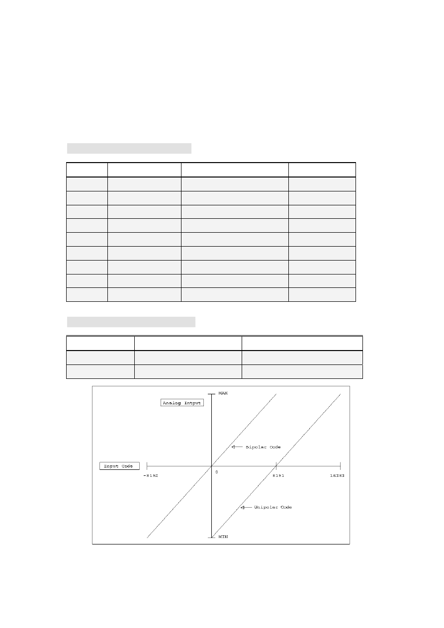
Input code format selection – JP1
Jumper position
Min. input code value
*1
Max. input code value
*2
B(Bipolar)
-8192
+8191
U(Unipolar)
0
16383
The MAX and MIN value in the vertical axis(analog input) represent the respective
maximum and minimal input signal for a specific type. For example, if the input
signal range set to –5V~+5V
*
1
– This value will be obtained when the input signal is –5V
*
2
– This value will be obtained when the input signal is +5V
The value shown above is the raw 14-bit input value read by CPU, the actual value
read by application is depends on the I/O configuration setting(Set by Winproladder
software)
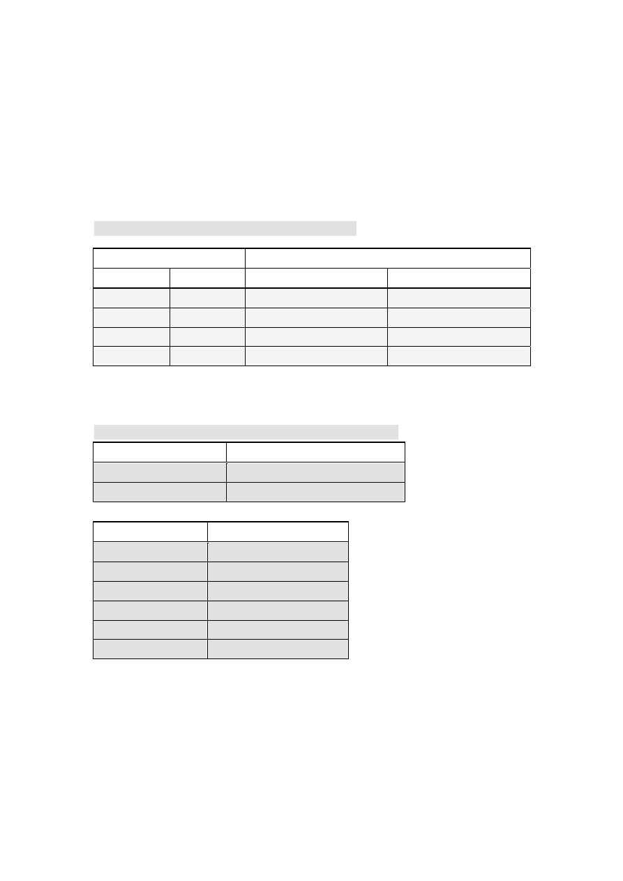
Input signal range and polarity setting – JP2,JP3
Jumper Location
Signal source type
*3
JP2 JP3
Voltage
Current
5V
B
-5V~+5V
-10 mA ~ +10 mA
10V
B
-10V~+10V
-20 mA ~ +20 mA
5V
U
0V ~ +5V
0 ~ +10 mA
10V
U
0V ~ +10V
0 ~ +20 mA
*
3
– Each channel can be individually set for voltage or current type signal.
Current or Voltage type input signal selection- JP4~JP9
Jumper Position
Signal Type
V
Voltage
I
Current
Input Channel
Jumper
CH0
JP4
CH1
JP5
CH2
JP6
CH3
JP7
CH4
JP8
CH5
JP9
Wyszukiwarka
Podobne podstrony:
data ftp PLC EthernetModule fbs ether enu
cat 6AD en id 108772 Nieznany
AfxOleCl enu (2)
AfxDb enu (2)
AfxDlg enu (2)
AfxOleSv enu (2)
fbs lista instrukcji id 168992 Nieznany
Ucieczka do?enu
AfxCore enu (2)
FBs B1 B1z Instruction List 0
DS SAM SAM SN S083F BEBE 01 ENU
FBs B1z B1 Specifications 1
Ch03 Expansion FBs PLC
więcej podobnych podstron