
Komputerowe
wspomaganie zarządzania
projektami
Prowadzący:
prof. dr hab. inż. Zenon
Ignaszak
Opracowali:
Marcin Hołysz
Jakub Jędraszak
Wojciech Szarycz
Rok 2011/2012

Bibliografia
• I. BABUSKA, L. LI, “The problem of plate modeling: Theoretical and
computational results”, Computer Methods in Applied Mechanics and
Engineering, 100(2), 1992, pp. 249-273.
• K.-J. BATH, “Finite element procedures”, Prentice-Hall Editor, ISBN:
0133014584, 1982.
• Y. BENHAFID, N. TROUSSIER., N. BOUDAOUD. “Towards the use of the
design of experiments method to control the quality of structural analysis”,
Sinaia (Rômania), 18-20 September, 2002, Mediarex 21.
• Y. BENHAFID, N. TROUSSIER, N. BOUDAOUD, Z. CHERFI. “Towards a
modelling assistance method in structural analysis. Application to a
terminal system of circuit breaker”, Proceedings of the 5th International
Conference on Integrated Design and Manufacturing in Mechanical
Engineering (IDMME'04), published by the University of Bath, UK, ISBN
1857901290, 2004.
• Y. BENHAFID, N. TROUSSIER., N. BOUDAOUD. “Méthode d’aide à
l’idéalisation de modèles issus de la CAO pour le calcul de structures“,
Mécanique & Industries, EDP Sciences, vol.6, n°3, 2005, pp. 289-296.
• M. BREUER. “Numerical and modeling influences on large eddy simulations
for the flow past a circular cylinder”, International Journal of Heat and Fluid
Flow, vol. 19, n°5, 1998, pp. 512-521.

• D. CASTILLO, C. DOUGLAS, D.R. MONTGOMERY. "Modified Desirability
Fonctions for Multiple Response Optimization", Journal of Quality
Technology, vol. 28, n° 3, 1996, pp. 337-345.
• S.C. CHAPRA, R.P. CANALE. “Numerical methods for engineers”, McGraw-
Hill, Editor, ISBN: 0071244298, 2005.
• W.Y. FOWLKES, C.M. CREVELING. “Ingénierie Robuste”. Dunod ed. Paris,
ISBN: 2100038109, 1998.
• P. KUROWSKI, B. SZABO. “How to find errors in finite-element models”.
Machine design, Paul Dvorak Editor, 25th of September, 1997, pp. 93-98.
• P. SCHIMMERLING, J.-C. SISSON, A. ZAIDI. “Pratique des plans
d'expériences“. Lavoisier Paris : Technique et Documentation, France, ISBN:
2743002395, 1998.
• D.A. SCHON. “The Reflective Practitioner: how professionals think in
action”, Arena Publisher, ISBN: 1857423194, 1991.
• N. TROUSSIER, F. POURROY, M. TOLLENAERE, B. TREBUCQ. “Mechanical
models management in engineering design”, Proceedings of the 2d
International Conference on Integrated Design and Manufacturing in
Mechanical Engineering (IDMME'98), Compiègne, France, Published by
Springer, ISBN 0792360249, 1998.

The control of the simulation quality and cost
using a multi-objective optimization method
and desirability functions
Kontrola jakości symulacji i kosztów za pomocą
wielo-celowej metody optymalizacji i funkcji
użyteczności
Yassine Benhafid
Université de Technologie de Compiègne, Laboratoire ODIC, BP 60319, 60203
Compiègne cedex, France, phone : 33 3 44234423 poste 42 21, fax :
33344235229, e-mail : yassine.benhafid@utc.fr
Nadège Troussier
Université de Technologie de Compiègne, Laboratoire ODIC, BP 60319, 60203
Compiègne cedex, France, phone : 33 3 44235230, fax: 33 3 44235229, e-mail :
nadege.troussier@utc.fr
Nassim Boudaoud
Université de Technologie de Compiègne, Laboratoire ODIC, BP 60319, 60203
Compiègne cedex, France, phone : 33 3 44237941, fax: 33 3 44235229, e-mail :
nassim.boudaoud@utc.fr

Abstract:
The simulation is a widely used tool for supporting the technical products
design. Numerous models have been developed until now that enable to take
into account the different levels in the accuracy of the physical phenomena
description. In addition, the simulation, and in particular structural analysis,
can be used to reach three different goals that are corresponding to three
different design contexts for using the simulation: the use of simulation in
order to understand a badly known phenomenon, the use of simulation in
order to compare the performances of various designs and the use of
simulation in order to validate the behaviour of a design.
Streszczenie:
Symulacja jest szeroko stosowanym narzędziem wspierającym projekt
techniczny produktu. Liczne modele stworzone do tej pory umożliwiają
uwzględnienie na różnych poziomach dokładność fizycznego opisu zjawiska.
Ponadto, symulację, w szczególności analizę strukturalną można wykorzystać
w celu osiągnięcia trzech różnych celów, które odpowiadają trzem różnym
kontekstom projektowym za pomocą symulacji: stosowania symulacji w celu
zrozumienia bardzo znanego zjawiska, korzystanie z symulacji w celu
porównania wykonań w różnych wariantach i wykorzystanie symulacji w celu
weryfikacji zachowania się konstrukcji.

Nowadays, the choice of the model adequate to a specific design context is made
by using the expert judgement. However, this judgement is often difficult to
achieve. Even if there are some experienced analysts, they need several iterations
in the analysis process to adjust the model to be used to reach the simulation
goal. The paper proposes to use a multi – objective optimisation method for
assistance to choose the model according to the kind of results to be obtained,
but especially according to the available time and the required accuracy of the
results to be obtained. The control of the quality and the cost of the simulation is
based on the use of the design of experiments, and on the evaluation of some
desirability functions to solve a multi-objective optimization problems.
Obecnie wybór modelu odpowiedniego do określonego projektu wykonywany jest
za pomocą ekspertyzy. Jednak decyzja ta jest często trudna do osiągnięcia. Nawet
jeśli jest kilku doświadczonych analityków, potrzebują oni kilku iteracji w procesie
analizy aby dostosować model, który ma być używany by osiągnąć cel symulacji.
Dokument proponuje wykorzystanie wielo-celowej metody optymalizacji przy
pomocy wyboru modelu w zależności od rodzaju wyników do uzyskania, ale
przede wszystkim w zależności od dostępnego czasu i wymaganej dokładności
wyników, które mają być uzyskane. Kontrola jakości i kosztów symulacji opiera się
na wykorzystaniu projektowania badań oraz na ocenie niektórych funkcji
użyteczności do rozwiązania wielu-celowych problemów optymalizacji.

Keywords: structural analysis, modelling, design
context, design of experiments, multiobjective
optimisation, desirability function
Słowa kluczowe: analiza strukturalna,
modelowanie, projektowanie kontekstowe,
projektowanie eksperymentów, wielocelowa
optymalizacja, funkcja użyteczności

Introduction
The use of simulation in the technical product design gains greater importance
during the recent years. One of its main advantages is its power to analyse non
existent products even before they exist. Many tools are used to simulate a real
product as the structural analysis for instance. The use of this tool in mechanical
simulation requires the management of different kind of hypotheses in order to
analyse the real complex system. In structural analysis, the idealization of a real
behaviour towards a model, that can be computed and solved, is a difficult task.
For the real system, when it will be used, a lot of factors and variations can affect
its structural behaviour. For instance, the material behaviour depends not only on
the material itself, but also on the heat treatment, the process, the environment of
use and so on.
Wprowadzenie
Zastosowanie symulacji w projekcie technicznym produktu nabiera większego
znaczenia w ostatnich latach. Jedną z głównych zalet symulacji jest możliwość
analizy produktu przed jego wprowadzeniem. Do symulacji wykorzystywanych jest
wiele narzędzi, jak na przykład analiza strukturalna. Wykorzystanie tego narzędzia
w symulacji wymaga od kierownictwa różnego rodzaju hipotez w celu analizy
złożonego systemu. W analizie strukturalnej, idealizacja zachowania w stosunku do
modelu, który można obliczyć i rozwiązać, jest trudnym zadaniem. Dla systemu,
kiedy będzie używany, wiele czynników i wahań może mieć wpływ na zachowanie
jego konstrukcji. Na przykład zachowanie tworzywa zależy nie tylko od rodzaju
materiału, lecz także od obróbki cieplnej, procesu, środowiska użytkowania itp.

However, it is nowadays impossible to take into account all these interactions
in an existing structural analysis model and choices have to be done.
Moreover, in an industrial context, the duration of the simulation, the
resources and the quality to be reached, influence these choices. The same
kind of choices among complex interactions between the technical system and
its environment all along its lifecycle leads to some idealization difficulties for
the boundary conditions, the geometrical simplifications, and the kind of
analysis (static or dynamic, linear or not). These simplifications choices imply
errors on the results obtained and must be controlled.
Obecnie jest jednak niemożliwe, aby brać pod uwagę wszystkie oddziaływania
w istniejącym modelu analizy strukturalnej, należy wybrać te, które muszą być
wykonane. Ponadto, w kontekście przemysłowym, czas trwania symulacji,
zasoby i jakość do osiągnięcia, mają wpływ na te decyzje. Ten sam rodzaj
wyborów wśród złożonych powiązań między systemem technicznym a jego
środowiskiem na każdym etapie cyklu jego życia prowadzi do pewnych
trudności idealizacji dla warunków brzegowych, uproszczenia geometrii i
rodzaju analizy (statyczne lub dynamiczne, liniowe lub nie). Te uproszczone
wybory oznaczają błędy w otrzymanych wynikach, co musi być kontrolowane.

A first step of idealization aims at answering the following
question: what is the physical law that has a mathematical
formulation or that has a suitable model available? A second
step remains after considering the feasibility of the computation
of the physical model, with analytical or discrete methods. These
two steps correspond to the construction of the physical model
and to the construction of the simulation models presented in
Figure 1:
Pierwszy krok idealizacji ma na celu odpowiedzieć na następujące
pytanie: czym jest prawo fizyczne, które ma matematyczne
sformułowanie lub które posiada odpowiedni dostępny model?
Drugim krokiem pozostaje, po uwzględnieniu możliwości
obliczania modelu fizycznego, wybór metod analitycznych lub
dyskretnych. Te dwa kroki są zgodne z budową modelu fizycznego
oraz konstrukcją modeli symulacyjnych przedstawionych na
rysunku 1:
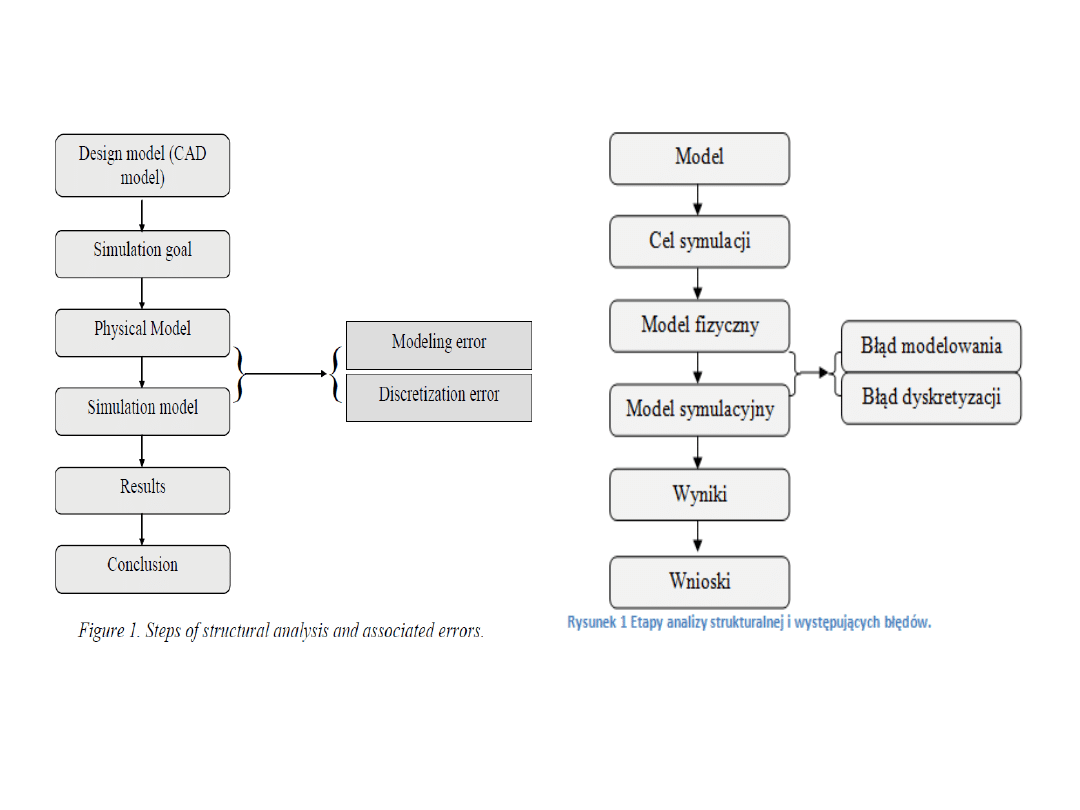

The structuring of the simulation process, presented in Figure 1,
points out two principal kinds of systematic errors involved in
the simulation process: the modelling error and the
discretization error. In order to achieve the discretization, some
authors propose methods and approaches allowing to control
these errors. However, the modelling error which needs to be
assessed by analysts. Nowadays, only human expertise can
help to control the modelling error control.
Strukturyzacja procesu symulacji, przedstawiona na rys. 1,
wskazuje dwa główne rodzaje błędów systematycznych
zaangażowanych w proces symulacji: błąd modelowania i błąd
dyskretyzacji. W celu osiągnięcia dyskretyzacji, niektórzy
autorzy zaproponowali metody i sposoby pozwalające
kontrolować te błędy. Jednak błąd modelowania, musi być
oceniany przez analityków. Obecnie tylko ludzka wiedza może
pomóc kontrolować błędy modelowania.

Physical modelling in the simulation
The first stage of a simulation skill is to idealize the real system towards a modelled
system. In other words, the analyst has to simplify the real system to be able to
model it by mathematical equations that can be solved by computational tools. In
this paper, we are focused on the necessary simplification of behaviour compared
with the real complex behaviour. The whole of these physical simplification
hypotheses of a studied system are chosen and formalized in the physical model,
depending on the aim of the simulation and the design context.
The aim of the simulation and the design context are characterized by three
parameters:
• the result to be obtained and the evaluation criterion that is associated to this
result,
• the quality level on the result to be obtained,
• the associated cost (the duration of the simulation).
Modelowanie fizyczne w symulacji
Pierwszym etapem umiejętności symulacji jest idealizowanie prawdziwego systemu
ku systemowi modelowemu. Innymi słowy, analityk ma na celu uproszczenie
prawdziwego systemu, aby mógł być modelowany przez równania matematyczne,
które mogą być rozwiązane przez narzędzia obliczeniowych. W niniejszym artykule
koncentrujemy się na koniecznych uproszczeniach zachowań w porównaniu z
rzeczywistym zachowaniem złożonym. Całość tych fizycznych hipotez
upraszczających badanego systemu jest wybierana i formalizowana w modelu
fizycznym, w zależności od celu symulacji i kontekstu projektu.
Cel symulacji i kontekstu projektowania charakteryzują trzy parametry:
• wynik do uzyskania i kryterium oceny, które wiąże się z wynikiem,
• poziom jakości wyniku do uzyskania,
• związany koszt (czas trwania symulacji).
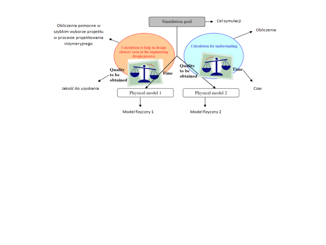
Figure 2 Impact of the design context on the building of the physical model.
Rysunek 2 Wpływ kontekstu projektowania na budowę modelu fizycznego.
The Figure 2 shows that two different contexts of use for the simulation lead to two different
physical models. The objective is to have the result as fast as possible, with a quality on this
result that just enables the qualitative evaluation of designs. On the other hand, some other
simulations are driven to understand precise phenomena and are controlled by the quality of
the results to be obtained. Thus, the physical model to be chosen should provide a maximum
level of quality, even if the simulation is time spending.
Rysunek nr 2 pokazuje, że dwa różne konteksty wykorzystania symulacji prowadzą do dwóch
różnych modeli fizycznych. Celem jest, aby wynik był otrzymany tak szybko jak to możliwe, z
takim skutkiem jakości, że po prostu umożliwia jakościową ocenę projektów. Z drugiej strony,
niektóre symulacje są napędzane zrozumieniem precyzyjnych zjawisk i są kontrolowane przez
jakość wyników, które mają być uzyskane. Tak więc, wybrany model fizyczny powinien
zapewnić maksymalny poziom jakości, nawet jeśli symulacja jest czasochłonna.

The method which is presented in this article, aims at helping
in the choice of the models to be simulated by taking into
account the engineering design context, by using the quality
and cost (duration) specifications to be obtained.
Metoda, która jest przedstawiona w tym artykule, ma na celu
pomoc w wyborze modeli do symulacji biorąc pod uwagę
kontekst projektu technicznego, przy użyciu jakości i kosztów
(czas trwania), jakie mają być uzyskane.

Our approach. The choice of the physical model to answer the
goal of simulation requires at the same time some knowledge
on the methods and tools specific to the structural analysis
and the experiment of the professional according to [12]. The
use
of
knowledge
developed
on
a
previous simulation case is a way commonly used by the
analysts: this has been observed during a one year
experiment carried out in an industrial company. This
observation is the base of our approach that proposes to
develop a reference case and to use it for all the similar
simulation cases that have to be analysed (Figure 3).
Nasz sposób
Wybór fizycznego modelu odpowiadający celowi symulacji
wymaga w tym samym czasie pewnej wiedzy na temat metod
i narzędzi do analizy strukturalnej i profesjonalnych
doświadczeń zgodnie z [12]. Korzystanie z wiedzy
opracowanej w poprzednim przypadku symulacji jest
sposobem powszechnie używanym przez analityków: to
zaobserwowano
podczas
jednego
roku
doświadczenia
przeprowadzonego przez firmę przemysłową. Jest to
podstawą naszego twierdzenia, które proponuje opracowanie
przypadku odniesienia i używanie go we wszystkich
przypadkach podobnej symulacji, które mają być analizowane
(rysunek 3).
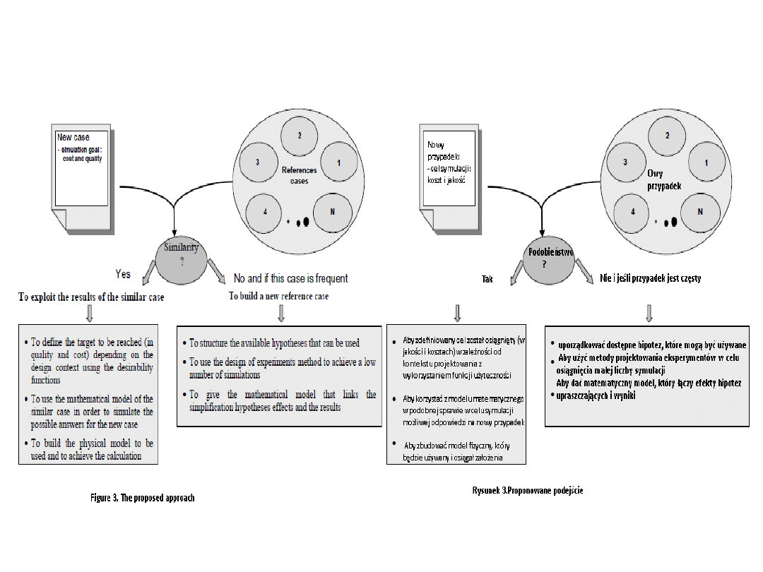

As described in the Figure 3, the references cases
are recurring cases which can provide knowledge on
the physical model to be chosen for a lot of similar
cases.
The similar cases are those which can be similar to
cases already analyzed and which can use
knowledge provided by the reference cases.
Jak opisano w rysunku trzecim, w owych
przypadkach występuję powtarzalność, która może
dostarczyć wiedzy na temat modelu fizycznego
wybieranego do wielu podobnych przypadkach.
Podobne przypadki to takie, które mogą być
podobne do analizowanych przypadków i które
opierają się na wiedzy z przypadków

The industrial experiment:
a recurrent knowledge for the choice of physical model
for various simulations during a one year period in an
automobile supplier firm, some observations have been made
in a Research and Development department and in a
specialized simulation department.
One of the most important points deals with the fact that the
knowledge of the physical model choice influence on the
result provided by the simulation is generic and appears
frequently in different simulations.
Doświadczenie przemysłowe:
powtarzająca się wiedza przy wyborze fizycznego modelu dla
różnych symulacje w okresie jednego roku w przedsiębiorstwie
dostawcy samochodów, niektóre obserwacje zostały dokonane
w
dziale
badawczo
-rozwojowym
oraz
w
dziale
specjalistycznych symulacji. Jednym z najważniejszych
punktów jest fakt, że poznanie fizycznego modelu wyborów
wpływ na wynik, który przewiduje symulacja jest i często
pojawia się w różnych symulacjach

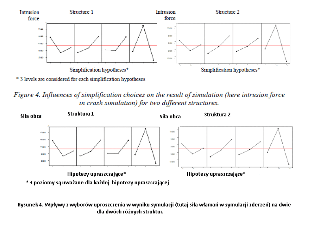
The Figure 4 shows the representation of the effect of different
simplification levels for different hypotheses (the boundary
conditions, the geometrical simplifications, the material behaviour)
on the intrusion force in crash simulation of two different structures.
It appears that the effect of the physical model choice is the same for
structure 1 and structure 2. In other words, the knowledge of the
effect of the hypotheses choices on the intrusion force can be used to
find a priori the physical model for simulating structure 2 and to
reach a good estimation of the intrusion force. The same kind of
representations of the influence of hypotheses on duration of
simulation has been made and leads to the same conclusion.
Rysunek 4 wskazuje efekty różnych uproszczeń na różnych
poziomach hipotezy (warunki brzegowe, geometryczne uproszczenia,
zachowanie materiału) na obce siły w symulacji zderzeń dwóch
różnych struktur. Wydaje się, że efekt wyboru fizycznego modelu jest
taki sam dla struktury 1 i struktury 2. Innymi słowy znajomość efektu
wyborów hipotezy sił obcych może służyć do znalezienia fizycznego
modelu dla symulacji struktury 2 i osiągnięcia dobrej oceny tych sił.
Tego samego rodzaju przedstawienie wpływu hipotez na czas trwania
symulacji zostały zrobione i doprowadziły do tych samych wniosków

The use of a reference case for helping in modelling choices
for a new similar case. In product design process, the
optimization of performances must take into account several
objectives to be reached. The aim of the optimization is then
to find the best compromises to fulfil the whole of the
objectives [8]. The formulation of optimization problems is
usually reduced to one objective function to be optimized
under several constraints. This objective function is built by
the combination of the different objective functions in the case
of a multi-objectives optimization.
Stosowania przypadku odniesienie pomaga w modelowaniu
wyboru nowych podobnych przypadków.
W
procesie
projektowania
produktu,
optymalizacja
parametrów musi być brana pod uwagę do osiągnięcia kilku
celów. Celem optymalizacji jest następnie znalezienie
najlepszych kompromisów do wypełnienia całościowego celu
[8]. Formułowanie problemów zazwyczaj redukuje do jednej
funkcji zoptymalizowanie kilku ograniczeń. Obiekt funkcji jest
zbudowany z kombinacji różnych funkcji celu w przypadku
wiele- obiektowej optymalizacji.

This combination is usually a weighted linear combination of the different
objectives functions. Other combination forms exist (loss functions, cost
functions, desirability functions). However, in our case, the desirability
function is an easily understandable concept because it corresponds to a
wish: to obtain a certain level of quality and of duration for the
simulation. This function is limited between 0 (minimum satisfaction
level) and 1 (maximum satisfaction level). In other words, the desirability
function makes possible to the user to subjectively evaluate the
relevance of the proposed optimums. For each objective function under
consideration, a desirability function is associated. By a combination of
each desirability functions, a global desirability is built (Figure 5). The
multi-objectives optimization problem is then to maximize the global
desirability.
Ta kombinacja jest zazwyczaj kombinacją liniową ważonej funkcji różnych
celi. Inne istniejące formy kombinacji (funkcje stracone, funkcje kosztu,
funkcje celu). Jednakże w naszym przypadku funkcja celu jest zrozumiałą
koncepcją, ponieważ odpowiada za: uzyskanie pewnego poziomu jakości i
czas trwania symulacji. Ta funkcja jest ograniczona między 0 (minimalny
zadowalający poziom) i 1 (poziom zadowolenia maksymalnego). Innymi
słowy funkcja celu umożliwia użytkownikowi ocenić subiektywnie
znaczenie proponowanego optimum. Dla każdej funkcji cel rozważanej
funkcji celu jest powiązany. Przez kombinację każdej funkcji celu, globalny
cel jest zbudowany (rysunek 5). Problem optymalizacji wiele- obiektowej
jest następnie zmaksymalizowany do globalnego celu.
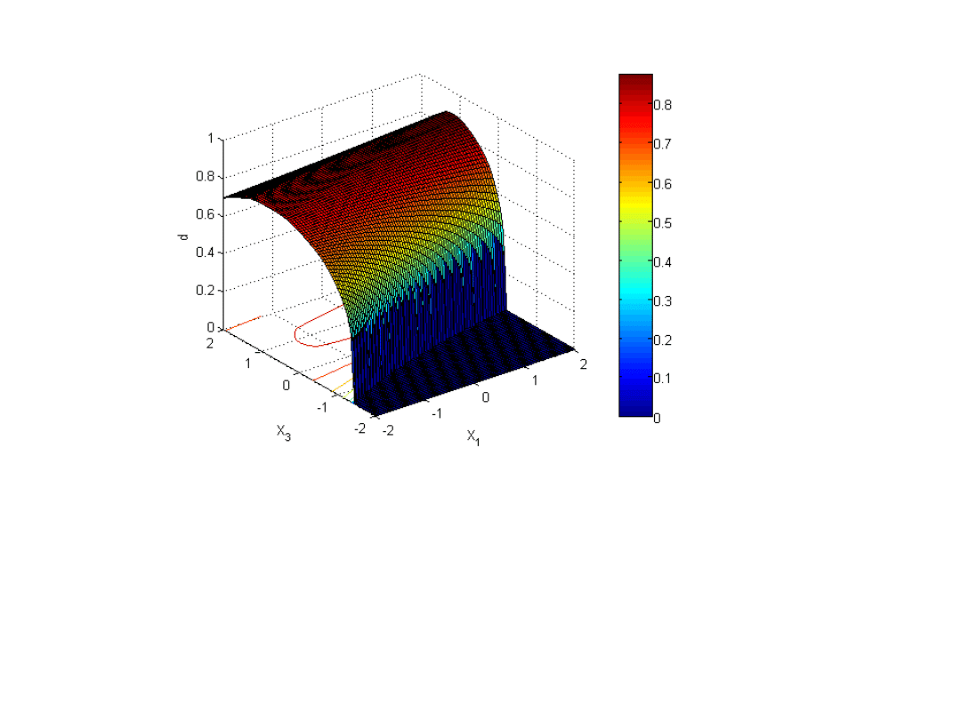
Figure 5. Illustration of the global desirability function in the
case of two responses.
Rysunek 5. Ilustracja funkcji globalnych celów w przypadku
dwóch odpowiedzi.

To solve this problem, using the previous considerations, the methodology
follows several steps:
• step 1: To give the target (objectives levels) to be reached in terms of quality
and cost (duration for the simulation) and to formulate the associated
desirability functions,
• step 2: To simulate all the different physical models by using the
mathematical
functions that are provided by the reference case, and to evaluate the global
desirability of each physical model,
• step 3: To propose the physical models that correspond to an acceptable
level of the global desirability evaluation in order to achieve the new case of
simulation.
In the following section, an illustration is provided to show more precisely how
to build a reference case and how to use it to help to achieve the modelling
choices on a new case, similar to the reference one.
Aby rozwiązać ten problem, za pomocą wcześniejszego rozważania, należy
wykonać kilka kroków:
• krok 1: ustalić cel (poziomy celu), który zostanie osiągnięty pod względem
jakości i kosztów (czas trwania symulacji) i formułowanie funkcji skojarzonych
celów,
• krok 2: aby symulować wszystkie różne modele fizyczne za pomocą funkcji
matematycznych, które są świadczone przez przypadek odniesienia oraz do
oceny globalnego celu każdego fizycznego modelu,
• krok 3: zaproponowanie fizycznych modeli, które odpowiadają
akceptowalnego poziomu oceny celu globalnego w celu osiągnięcia nowego
przypadku symulacji. W poniższej sekcji ilustracji znajduje się bardziej
dokładnie jak budować przypadek odniesienia i jak go używać, aby pomóc w
osiągnięciu modelowanych wyborów jako nowy przypadek, podobne do
odniesienia pierwszego

The application example of the modelling approach presented in this paper is
a terminal system of circuit breaker (Figure 6). In a circuit breaker, the
terminal system is used to connect electrical wires to the circuit breaker. The
several difficulties in the maintaining of the terminal system in a circuit
breaker are due to the resistance to the different electrical and mechanical
excitations. This work is focused on the study of torsion and traction
excitations applied on the terminal system. The objective of this work is to
guide an analyst to carry out his choices of the hypotheses of the physical
modelling in the analysis of the terminal systems.
Przykład zastosowania tego podejścia do modelowania, przedstawiony w
niniejszym opracowaniu jest system zacisków (Rysunek 6). W wyłączniku,
system zacisków służy do podłączenia przewodów elektrycznych do
wyłącznika. Kilka trudności w utrzymaniu systemu zacisków w wyłączniku
wynika ze względu na odporność dla różnych wzbudzeń mechanicznych i
elektrycznych. Praca ta koncentruje się na badaniu skręcania i trakcji
wymuszeń stosowanych w systemie zacisków. Celem tej pracy jest
poprowadzenie analityka do dokonania swoich wyborów hipotez fizycznego
modelowania w analizie systemu zacisków.
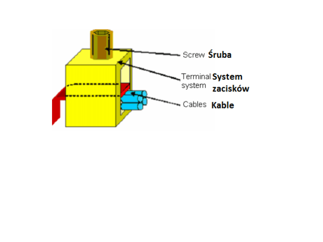
Figure 6. Description of the terminal system of circuit breaker.
Rysunek 6. Opis systemu zacisków wyłącznika.
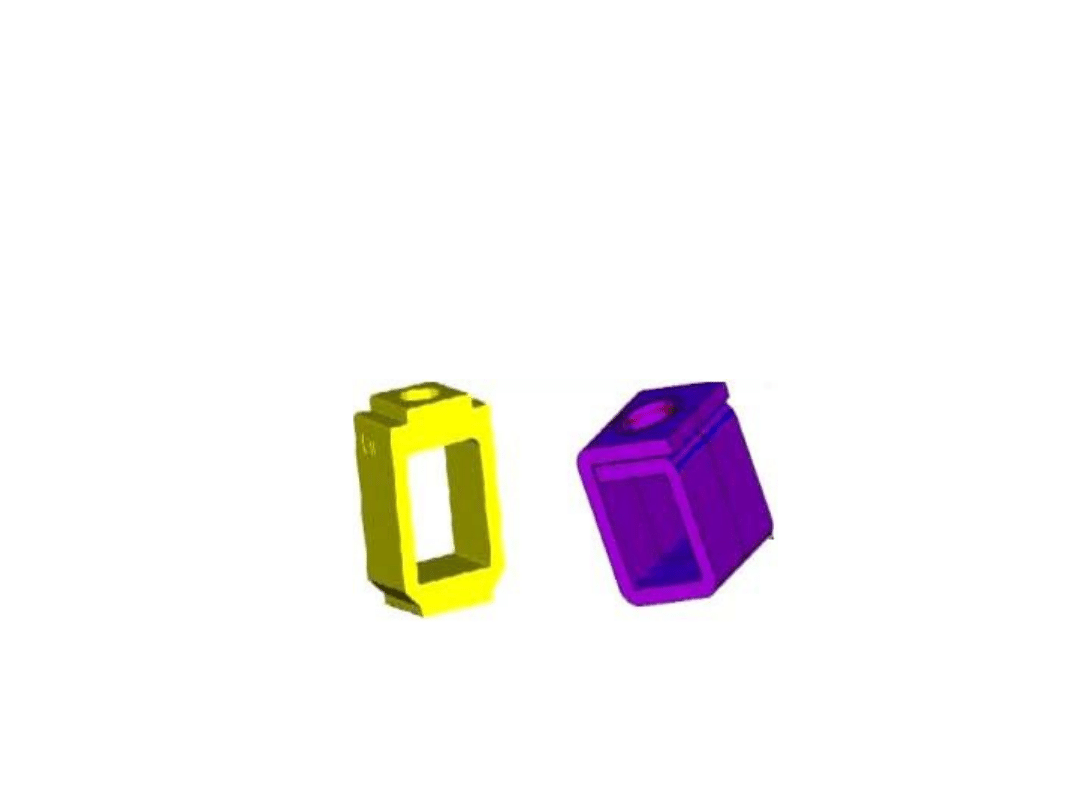
The example shows the main steps for the exploitation of the results of a
reference case. The Figure 7 - A presents the reference case and the Figure 7
- B, the similar case for which the physical model to be implemented has to
be chosen.
Przykład pokazuje główne etapy dla eksploatacji wyników w przypadku
odniesienia .
Rysunek 7 – Przedstawia przypadek odniesienia i Rysunek 7 - B, podobna
sytuacja, w której model fizyczny do realizacji ma być wybrany.
Figure 7. The reference case and the similar case used for the illustration.
Rysunek 7.Przypadek odniesienia i podobny przypadek wykorzystany do
ilustracji.
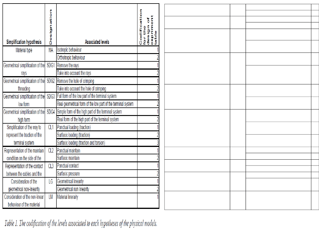
Tabela 1.Ujednolicenie poziomów związanych z
poszczególnymi hipotezami fizycznych modeli.
Typ materiału
MA
Zachowanie izotropiczne
1
Zachowanie orotropiczne
2
Geometryczne
uproszczenie promieni
SDG1 Usunięcie promieni
1
Branie pod uwagę promieni 2
Geometryczne
uproszczenie gwintów
SDG2 Usunięcie otworu
karbowania
1
Branie pod uwagę otworu
karbowania
2
Geometryczne
uproszczenie niskiej formy
SDG3 Pełna forma niskiej części
systemu zacisków
1
Rzeczywista geometryczne
forma małej części systemu
zacisków
2
Geometryczne
uproszczenie wysokiej
formy
SDG4 Prosta forma dużej części
systemu zacisków
1
Rzeczywista forma dużej
części systemu zacisków
2
Uproszczenie sposobu
reprezentowania trakcji
(przyczepności) systemów
zacisków (systemów trakcji)
CL1
Dokładne obciążenie
(rozciąganie)
1
Punktowe obciążenie
(rozciąganie)
2
Powierzchniowe obciążenie
(rozciąganie i skręcanie)
3
Reprezentacja utrzymania
kondycji ze strony
CL2
Punktowe utrzymanie
1
Powierzchniowe utrzymanie 2
Reprezentacja kontaktu
pomiędzy liniami
CL3
Kontakt punktowy
1
Naciski powierzchniowe
2
Przemyślenia (rozważania)
na temat geometrycznej
nieliniowości
LG
Geometryczna liniowość
1
Geometryczna nieliniowość 2
Rozważania na temat
zachowania nieliniowości
materiału
LM
Liniowość materiału
1
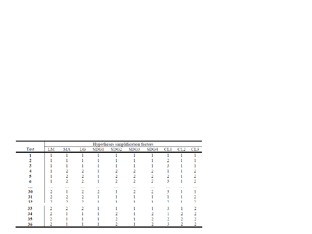
For the reference case (Figure 7 - A), an experimental table (Table 2) is achieved.
This table is a fractional experimental design composed of 36 physical models.
Therefore, the realization of this table gives us 36 results on Von Mises stress (at the
critical point : top level of the circuit breaker) and 36 results on computation
duration. The different hypotheses under consideration are those on material
behaviour, X MA (isotropic (1) or orthotropic (2)), on material linearity, X LM (linear
(1) or bilinear (2)), and so on (geometric linearity, geometrical details
simplifications, Boundary conditions…), as described in Table 1.
Dla przypadku odniesienia (Rys. 7 -), została wykonana eksperymentalna tabela
(tabela 2). Ta tabela jest ułamkowa, eksperymentalny projekt składa się z 36 modeli
fizycznych. Dlatego też realizacja tej tabeli daje nam 36 wyników na naprężenia von
Misesa w punkcie krytycznym: (górny poziom wyłącznika) i 36 wyników na czas
obliczeń. Różne hipotezy rozważane są na zachowania materiału, X MA (izotropowy
(1) lub ortotropowe (2)), na liniowość materiału, X LM (liniowy (1) lub dwuliniowy
(2)), i tak dalej (geometryczny liniowość, geometryczne detale uproszczeń, warunki
brzegowe...), jak opisano w tabeli 1.
Table 2. Extract of the
experiments table (table L36).
Tabela 2. Wyciąg z
eksperymentalnej tabeli
(tabela L36).
czynnik uproszczenie
hipotezy
test
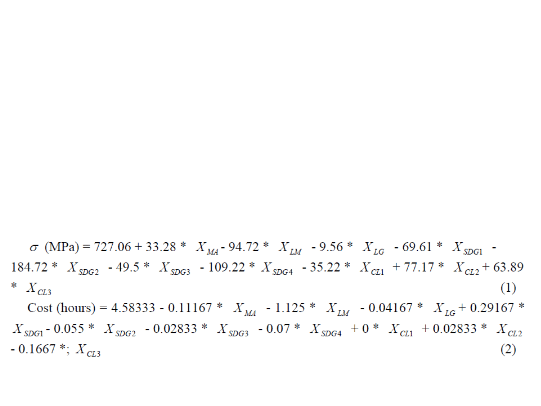
The equations (1) and (2) are the polynomial models developed with the 36 results
which are obtained by the simulations. The equation (1) is dealing with the Von Mises
stress evaluation at the critical point (top level of the circuit breaker), and the equation
(2), the cost evaluation (in terms of duration). Owing to the fact that the equations (1)
and (2) summarize the results of the influence study for the reference case (Figure 7 -
A), the physical model for a similar case (Figure 7 - B) can be selected, based on these
equations.
Równania (1) i (2) to wielomianowe modele opracowane z 36 wyników, które
otrzymywane są przez symulacje. Równanie (1) ma do czynienia z oceną naprężeń von
Misesa w punkcie krytycznym (górny poziom wyłącznika) oraz równania (2), ocena
kosztów (w zakresie czasu trwania). Ze względu na fakt, że równania (1) i (2)
podsumowanie wyników badań wpływu dla przypadku odniesienia (Rys. 7 -), model
fizyczny dla podobnej sprawy (Rysunek 7 - B) może być wybrany w oparciu na tych
równaniach.

For the new simulation case, by using the mathematical models (1) and (2), the whole
of the results for the possible physical models is generated. In our case, 1536 results
were generated in a very short time (less than one second on a basic office computer)
(Figure 8).
Dla nowego przypadku symulacji, za pomocą modeli matematycznych (1) i (2),
generowana jest całość wyników dla możliwych modeli fizycznych. W naszym
przypadku 1536 wyników zostało wygenerowanych w bardzo krótkim czasie (mniej niż
jedna sekunda na podstawowym komputerze biurowym) (rys. 8).
Figure 8. Distribution of results for
the terminal of circuit breaker:
complete field
Real tests of computations,
starting
from
a
mathematical
model.
Rysunek 8. Rozkład wyników dla
zacisku wyłącznika:
pełne pole
Prawdziwe
testy
obliczeń,
począwszy
od
modelu
matematycznego.

The context of simulation is then used via the specification of the objective functions.
The first objective function relates to the quality Q = 75% and the second objective
function relates to the cost (duration) of the simulation T<4 hours.
Konteksty symulacji są następnie wykorzystywane przez specyfikację funkcji celu.
Pierwsza funkcja celu odnosi się do jakości Q = 75% i druga funkcja celu odnosi się do
kosztów (czas trwania) symulacji T <4 godziny.
Figure 9. The different desirability functions : desirability function for the quality and for
the cost
Rysunek 9. Różne cele funkcji: funkcja użyteczności dla jakości i dla kosztów
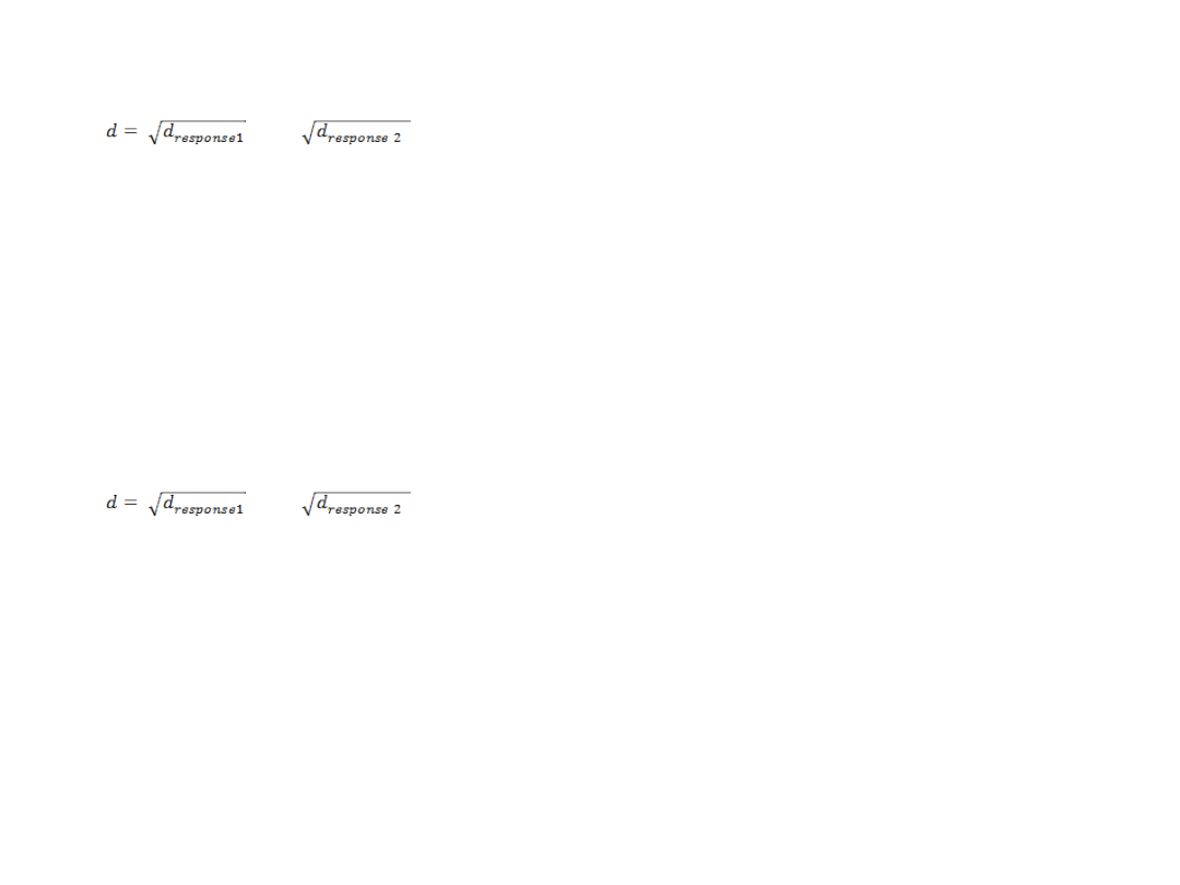
The maximum value of the total desirability given by the
product:
*
is finally researched among the 1536 values of possible d. The optimal
model to be implemented is then the one which corresponds to the
maximum of d. In other words, it is the model which answers the best the
objectives of cost of simulation and quality on the Von Mises stress.
Maksymalna wartość całkowitej celowości dana przez
produkt:
*
jest ostatecznie zbadana pośród 1536 możliwych wartości d. Optymalny
model realizowany jest wtedy gdy jeden z nich odpowiada maksymalnej d.
Innymi słowy, jest to model, który najlepiej odpowiada celom kosztów
symulacji i jakość na naprężenia von Misesa.

In the case of the terminal, we find the results following with Q for the quality and T
for the cost: Q=76%,
T = 3 hours. The corresponding model to these values is defined by the levels of the
following hypotheses: isotropic material (MA=1), large displacements, large
deformations (LG=2), law of nonlinear behaviour (LM=2), consider the hole of
setting (SDG2=2), real shape of the geometry of the top of the terminal (SDG3=2),
real shape of the geometry of the bottom of the terminal (SDG4=2), surface effort
applied in top of the terminal (CL1=2), punctual effort applied in bottom of the
terminal (CL3=1).
W przypadku zacisku, znajdujemy następujące wyniki z Q dla jakości i T dla kosztów:
Q = 76%, T = 3 godziny Odpowiedni model do tych wartości jest określony przez
poziom następujących hipotez: izotropowy materiał (MA = 1), duże
przemieszczenia, duże deformacje (LG = 2), prawo zachowania nieliniowości (LM =
2), należy rozważyć otwór ustawienia (SDG2 = 2), rzeczywisty kształt geometrii
góry zacisku SDG3 = 2), rzeczywisty kształt geometrii dołu zacisku SDG4 = 2),
wysiłek powierzchni stosowany w górnej części zacisku CL1 = 2), ,Nacisk punktowy
stosować w dolnej części terminala CL3 = 1).

Conclusion
A methodology for assistance of modelling choice for mechanical structural
analysis has been proposed. It is based on the use of similarity properties
between different simulation cases [5]. The design of experiments is used for
structuring some reference cases, and the use of desirability functions and
multi-objective optimization provide some indication for a new simulation case,
similar to the reference one. The automatic treatment of the reference case in
order to provide the physical models acceptable for the new case has been
developed with MATLAB® software.
Wnioski
Metodologia pomocy wyboru modelowania mechanicznej analizy strukturalnej
została zaproponowana. Opiera się na wykorzystaniu właściwości podobieństwa
pomiędzy różnymi przypadkami symulacji [5].Projektowanie eksperymentów jest
używane do strukturyzacji niektórych przypadków odniesienia, a korzystanie z
funkcji użyteczności i wielocelowej optymalizacji prowadzi do dostarczenia
pewnych wskazówek dla nowego przypadku symulacji, podobny do tego
odniesienia. Automatyczne obróbka przypadku odniesienia prowadzona jest w
celu zapewnienia fizycznych modeli akceptowanych dla nowego przypadku który
został opracowany z oprogramowaniem MATLAB ®.

References /Odnośniki
[1] I. BABUSKA, L. LI, “The problem of plate modeling: Theoretical and computational results”,
Computer Methods in Applied Mechanics and Engineering, 100(2), 1992, pp. 249-273.
[2] K.-J. BATH, “Finite element procedures”, Prentice-Hall Editor, ISBN: 0133014584, 1982.
[3] Y. BENHAFID, N. TROUSSIER., N. BOUDAOUD. “Towards the use of the design of
experiments method to control the quality of structural analysis”, Sinaia (Rômania), 18-20
September, 2002, Mediarex 21.
[4] Y. BENHAFID, N. TROUSSIER, N. BOUDAOUD, Z. CHERFI. “Towards a modelling assistance
method in structural analysis. Application to a terminal system of circuit breaker”,
Proceedings of the 5th International Conference on Integrated Design and Manufacturing in
Mechanical Engineering (IDMME'04), published by the University of Bath, UK, ISBN
1857901290, 2004.
[5] Y. BENHAFID, N. TROUSSIER., N. BOUDAOUD. “Méthode d’aide à l’idéalisation de modèles
issus de la CAO pour le calcul de structures“, Mécanique & Industries, EDP Sciences, vol.6,
n°3, 2005, pp. 289-296.
[6] M. BREUER. “Numerical and modeling influences on large eddy simulations for the flow
past a circular cylinder”, International Journal of Heat and Fluid Flow, vol. 19, n°5, 1998, pp.
512-521.
[7] D. CASTILLO, C. DOUGLAS, D.R. MONTGOMERY. "Modified Desirability Fonctions for Multiple
Response Optimization", Journal of Quality Technology, vol. 28, n° 3, 1996, pp. 337-345.
[8] S.C. CHAPRA, R.P. CANALE. “Numerical methods for engineers”, McGraw-Hill, Editor, ISBN:
0071244298, 2005.
[9] W.Y. FOWLKES, C.M. CREVELING. “Ingénierie Robuste”. Dunod ed. Paris, ISBN:
2100038109, 1998.
[10]P. KUROWSKI, B. SZABO. “How to find errors in finite-element models”. Machine design,
Paul Dvorak Editor, 25th of September, 1997, pp. 93-98.
[11]P. SCHIMMERLING, J.-C. SISSON, A. ZAIDI. “Pratique des plans d'expériences“. Lavoisier
Paris : Technique et Documentation, France, ISBN: 2743002395, 1998.
[12]D.A. SCHON. “The Reflective Practitioner: how professionals think in action”, Arena
Publisher, ISBN: 1857423194, 1991.
[13]N. TROUSSIER, F. POURROY, M. TOLLENAERE, B. TREBUCQ. “Mechanical models
management in engineering design”, Proceedings of the 2d International Conference on
Integrated Design and Manufacturing in Mechanical Engineering (IDMME'98), Compiègne,
France, Published by Springer, ISBN 0792360249, 1998.
Document Outline
- Slide 1
- Slide 2
- Slide 3
- Slide 4
- Slide 5
- Slide 6
- Slide 7
- Slide 8
- Slide 9
- Slide 10
- Slide 11
- Slide 12
- Slide 13
- Slide 14
- Slide 15
- Slide 16
- Slide 17
- Slide 18
- Slide 19
- Slide 20
- Slide 21
- Slide 22
- Slide 23
- Slide 24
- Slide 25
- Slide 26
- Slide 27
- Slide 28
- Slide 29
- Slide 30
- Slide 31
- Slide 32
- Slide 33
- Slide 34
- Slide 35
- Slide 36
- Slide 37
Wyszukiwarka
Podobne podstrony:
Ebsco Gross The cognitive control of emotio
The Hormonal Control of Sexual?velopment
Ebsco Gross The cognitive control of emotio
Microwave irradiation of hazelnuts for the control of aflatoxin producing Aspergillus parasiticus
The Discrete Time Control of a Three Phase 4 Wire PWM Inverter with Variable DC Link Voltage and Bat
the struggle over control of kievdimnik
The Discrete Time Control of a Three Phase 4 Wire PWM Inverter with Variable DC Link Voltage and Bat
Domjan M , Cusato B Pavlovian feed forward mechanisms in the control of social behavior
Kim Control of auditory distance perception based on the auditory parallax model
Ebsco Gross The cognitive control of emotion
Farina, A Pyramid Tracing vs Ray Tracing for the simulation of sound propagation in large rooms
Who s Pulling Your Strings (How To Break The Cycle Of Manipulation And Regain Control Of Your Lif
Pfeffer The external control of organizations
Barrow, John D Living in the Simulated Universe
Bostrom, Nick The Simulation Argument Some Explanations
Johnson, David Kyle Natural Evil and the Simulation Hypothesis
Bostrom, Nick; Kulczycki, Maciej A Patch For the Simulation Argument
więcej podobnych podstron