
©
A
B
B
C
o
n
tr
o
l
tr
a
in
in
g
P
a
g
e
-
1
-
A
C
3
1
4
0
&
5
0
s
e
ri
e
s
Insert
image
here
AC31
Training
ABB
Automation

©
A
B
B
C
o
n
tr
o
l
tr
a
in
in
g
P
a
g
e
-
2
-
A
C
3
1
4
0
&
5
0
s
e
ri
e
s
Schedule

©
A
B
B
C
o
n
tr
o
l
tr
a
in
in
g
P
a
g
e
-
3
-
A
C
3
1
4
0
&
5
0
s
e
ri
e
s
Insert
image
here
- 1 -
Installation
ABB
Automation

©
A
B
B
C
o
n
tr
o
l
tr
a
in
in
g
P
a
g
e
-
4
-
A
C
3
1
4
0
&
5
0
s
e
ri
e
s
40 and 50 series central units
Central
Unit 40
07KR51 / 07KT51: 50 series
central units d
ecentralized with
CS31 bus
07CT41/ 07CR41
Standalone
8 opto-isolated inputs 24Vdc type PNP or NPN
6 relay outputs 250V a.c. / 2A
or 6 transistor outputs :
2 outputs 24 VDC, 1A
4 outputs 24 VDC , 0.5 A
Central
Unit 50
Power supplies available: 24 VDC, 120/230VAC

©
A
B
B
C
o
n
tr
o
l
tr
a
in
in
g
P
a
g
e
-
5
-
A
C
3
1
4
0
&
5
0
s
e
ri
e
s
40 and 50 series central units
Removable
wiring cover,
Wiring diagrams printed
on product
Connector
for
extension
Serial
communication to
PC and MODBUS
network
2 adjustable
potentiometers
for
timer,
temperature...
Direct earthling
via DIN rail or
fixing screw
Better EMC
Removable
connectors :
Cage Clamp or
dual (option)
CS31 bus or
Modbus network
RS485

©
A
B
B
C
o
n
tr
o
l
tr
a
in
in
g
P
a
g
e
-
6
-
A
C
3
1
4
0
&
5
0
s
e
ri
e
s
40 and 50 series central units
Positive logical inputs PNP
with 120/230 V a.c. or 24 V
d.c.
Negative logical inputs NPN
with 120/230 V a.c. or 24 V d.c.

©
A
B
B
C
o
n
tr
o
l
tr
a
in
in
g
P
a
g
e
-
7
-
A
C
3
1
4
0
&
5
0
s
e
ri
e
s
40 and 50 series central units
Relay outputs
Transistor outputs

©
A
B
B
C
o
n
tr
o
l
tr
a
in
in
g
P
a
g
e
-
8
-
A
C
3
1
4
0
&
5
0
s
e
ri
e
s
40 series - standalone central units
A big one for small applications
(typical up to 110 I/O)
34 Kbytes FlashEprom memory ie typical 8000
instructions
0,4 ms cycle time for 1 kbyte binary
Encoder Input 7Khz or 2 high
speed counters 5Khz
1 impulse output
PI and PID regulation
Password
Unlimited timers and counters
Incorporated battery for data
back-up
Central
Unit 40
H
High performance through hard- and
software
Subprogramming (12)
2 interrupts
Direct access to I/O
2 cyclic tasks
Real Time Clock
Communication
ASCII and Modbus
(RS232)

©
A
B
B
C
o
n
tr
o
l
tr
a
in
in
g
P
a
g
e
-
9
-
A
C
3
1
4
0
&
5
0
s
e
ri
e
s
50 series - Decentralized central units
Powerful modular conception
Same characteristics than 40 series central
units
34 Kbytes FlashEprom memory ie typical
8000 instructions
0,4 ms cycle time for 1 kbyte binary
Central
Unit 50
Additional features
Automatic
switchable
RS485/232 serial communication
CS31 twisted-pair for extensions up to 2000 meters with
3 bus repeaters
CS31 bus switched in MODBUS master or slave
Max 920 Binary Inputs and 494 Outputs / 258 AI or 120
AO

©
A
B
B
C
o
n
tr
o
l
tr
a
in
in
g
P
a
g
e
-
1
0
-
A
C
3
1
4
0
&
5
0
s
e
ri
e
s
Inputs/outputs remote units
ICMK 14F1 & ICMK
14N1
CS31 twisted-pair remote
unit
8 opto-isolated inputs
24Vdc
type PNP or NPN
6 relay outputs 250V a.c. /
2A
or 6 transistor outputs :
2 outputs 24 VDC, 1A
4 outputs 24 VDC , 0.5 A
Accepts 6 I/O extension
units
analog
(max. 2)
or binary

©
A
B
B
C
o
n
tr
o
l
tr
a
in
in
g
P
a
g
e
-
1
1
-
A
C
3
1
4
0
&
5
0
s
e
ri
e
s
Binary extensions
XI16E1 : - 16 opto-isolated inputs 24VDC
- Type PNP.
XO08R1 : - 8 outputs relay 250A / 2A
- 2 independent commons
XC08L1 : - 8 user configurable channels
- Inputs / outputs 24VDC,0.5A
XK08F1 : - 4 inputs 24VDC type PNP/NPN
- 4 outputs relay
XO16N1 : - 16 outputs transistors
24VDC
/ 0.5A
- 1 independent commons
All binary extensions have self-
configuration

©
A
B
B
C
o
n
tr
o
l
tr
a
in
in
g
P
a
g
e
-
1
2
-
A
C
3
1
4
0
&
5
0
s
e
ri
e
s
Binary extensions
XI16E1
XO08R1
XC08L1
XK08F1
XO16N1

©
A
B
B
C
o
n
tr
o
l
tr
a
in
in
g
P
a
g
e
-
1
3
-
A
C
3
1
4
0
&
5
0
s
e
ri
e
s
Binary extensions
XO08Y1 :
- 8 Transistor outputs
24VDC / 2A
- 1 independent common
XO08R2 : - 4 Relay outputs NO 250V / 2A
- 4 Relay outputs NO/NC 250V /
3A
- 8 independent commons
All binary extensions have self-
configuration

©
A
B
B
C
o
n
tr
o
l
tr
a
in
in
g
P
a
g
e
-
1
4
-
A
C
3
1
4
0
&
5
0
s
e
ri
e
s
Binary extensions
XO08Y1
XO08R2

©
A
B
B
C
o
n
tr
o
l
tr
a
in
in
g
P
a
g
e
-
1
5
-
A
C
3
1
4
0
&
5
0
s
e
ri
e
s
A CS31 bus is a RS485 serial interface
•
A shield twisted pair RS485
(the twisted pair has to be
symmetric )
• Master/Slave protocol:
1 master central unit on the
bus
It can manage up to 31 connection
points
• Maximal length
:
500 m without amplifier
2000 m with 3 amplifiers (NCBR or
NCB)
CS31 Bus

©
A
B
B
C
o
n
tr
o
l
tr
a
in
in
g
P
a
g
e
-
1
6
-
A
C
3
1
4
0
&
5
0
s
e
ri
e
s
• Bus interruptions should be avoided, during
cabinet cable connections for
instance,otherwise it should be cabled to the
same side of the terminal block
• A same cable type should be used for the
whole system bus
CS31 Bus

©
A
B
B
C
o
n
tr
o
l
tr
a
in
in
g
P
a
g
e
-
1
7
-
A
C
3
1
4
0
&
5
0
s
e
ri
e
s
• Warning:
Star connection of the bus is
Forbidden
Allowed
wiring
Forbidden
wiring
• The bus should be terminated with a 120 1/4
W resistance connected to the bus extremities
CS31 Bus

©
A
B
B
C
o
n
tr
o
l
tr
a
in
in
g
P
a
g
e
-
1
8
-
A
C
3
1
4
0
&
5
0
s
e
ri
e
s
• In case of noisy elements in the area of
the cabinet, connect the bus shield to the
ground via a capacitor 1 nF class Y directly
at the access of the cabinet.
CS31 Bus

©
A
B
B
C
o
n
tr
o
l
tr
a
in
in
g
P
a
g
e
-
1
9
-
A
C
3
1
4
0
&
5
0
s
e
ri
e
s
• Same earth for all AC31 products :
Connection
as short as possible.
When the remote units are
outside the cabinet, they must be connected to
the nearest earth.
Earthing principles

©
A
B
B
C
o
n
tr
o
l
tr
a
in
in
g
P
a
g
e
-
2
0
-
A
C
3
1
4
0
&
5
0
s
e
ri
e
s
• In case of noisy element, the connection to the
earth has to be near the noisy element
Earthing principles

©
A
B
B
C
o
n
tr
o
l
tr
a
in
in
g
P
a
g
e
-
2
1
-
A
C
3
1
4
0
&
5
0
s
e
ri
e
s
Insert
image
here
- 2 -
AC31
Addressing
ABB
Automation

©
A
B
B
C
o
n
tr
o
l
tr
a
in
in
g
P
a
g
e
-
2
2
-
A
C
3
1
4
0
&
5
0
s
e
ri
e
s
I Binary input
IW Analog input
O Binary output
OW Analog output
Channe
l
number
Addres
s
unit
%IW
0 0
0
0
.
x
x
x
x
Addressing inputs/outputs

©
A
B
B
C
o
n
tr
o
l
tr
a
in
in
g
P
a
g
e
-
2
3
-
A
C
3
1
4
0
&
5
0
s
e
ri
e
s
• Standalone or master mode + 6
analog or binary extensions
62
for central unit and
63 to 68
for
extensions
Addressing Central units

©
A
B
B
C
o
n
tr
o
l
tr
a
in
in
g
P
a
g
e
-
2
4
-
A
C
3
1
4
0
&
5
0
s
e
ri
e
s
On the master central
unit
Automatically
Address is 62
On the
extensions
Assigned
automatically
Addresses are 63 to
68
How ?

©
A
B
B
C
o
n
tr
o
l
tr
a
in
in
g
P
a
g
e
-
2
5
-
A
C
3
1
4
0
&
5
0
s
e
ri
e
s
n° 62
62+1
+
1
+
1
+
1
+
1
+
1
Example: 62
63 64 65 66 65
66
I&O I&O
O
I
I
O
On central
unit:
Automatically, it depends of the type , the
situation :
Mixed or configurable I&O, input I,
output O.
Addressing binary extensions

©
A
B
B
C
o
n
tr
o
l
tr
a
in
in
g
P
a
g
e
-
2
6
-
A
C
3
1
4
0
&
5
0
s
e
ri
e
s
62
Ana
I&O
Ana
I&O
Ana.
I&O
Bin.
I&O
Ana.
I&O
Binaire
I&O
6
3
6
4
6
5
6
6
6
3
6
4
+
1
+
1
+
1
+
1
+
1
On central
unit:
Automatically, addresses 63
to 68
Addressing analog extensions

©
A
B
B
C
o
n
tr
o
l
tr
a
in
in
g
P
a
g
e
-
2
7
-
A
C
3
1
4
0
&
5
0
s
e
ri
e
s
The CS31 protocol is a master/slave
protocol :
•
The slaves are indicated by an address
between 0 to 61
- The addressing is not according to the order of the units
on the bus
- The addresses from 0 to 61 may be attributed in any
order to the
slaves.
• The master CPU can manage up to 31
connection points
- Example of connection point:
A non extensible remote unit
An extensible remote unit with binary extensions
A central unit ( 50 serie with extensions, 90 or 30
series )
A variable speed drive ABB NCSA-01 interface…...
-
Warning :
An extensible remote unit with analog
extensions counts
2 connection points.
Addressing on CS31 bus

©
A
B
B
C
o
n
tr
o
l
tr
a
in
in
g
P
a
g
e
-
2
8
-
A
C
3
1
4
0
&
5
0
s
e
ri
e
s
Master
CPU
Extensible remote
units
+ extensions
or
Slave central units
Addresses
00 to 61
Authorized Addresses on C31 bus

©
A
B
B
C
o
n
tr
o
l
tr
a
in
in
g
P
a
g
e
-
2
9
-
A
C
3
1
4
0
&
5
0
s
e
ri
e
s
On the extensible remote
units
By rotative switches
For tens
For
units
How ?

©
A
B
B
C
o
n
tr
o
l
tr
a
in
in
g
P
a
g
e
-
3
0
-
A
C
3
1
4
0
&
5
0
s
e
ri
e
s
Addressing binary extensions
Master
CPU
n° X
X+1
+
1
+
1
+
1
+
1
+
1
Example: 10
11
12 13 14
13 14
I&O I&O
O
I
I
O
Extensibl
e
remote
unit
CS31
bus
On extensible
unit:
Automatically, it depends of the type ,
the situation :Mixed or configurable I&O,
input I, output O.

©
A
B
B
C
o
n
tr
o
l
tr
a
in
in
g
P
a
g
e
-
3
1
-
A
C
3
1
4
0
&
5
0
s
e
ri
e
s
it takes the same address
value as that of the
extensible remote unit
Max : 8 analog input channels and
8 analog output channels
extensions
On extensible remote
unit:
Extensibl
e
remote
unit
Master
CPU
n° X
X
IW xx ,00 to IW xx ,
07
OW xx,00 to OW xx ,
07
CS31
bus
Addressing analog extensions

©
A
B
B
C
o
n
tr
o
l
tr
a
in
in
g
P
a
g
e
-
3
2
-
A
C
3
1
4
0
&
5
0
s
e
ri
e
s
IW xx ,04 to IW xx ,
07
OW xx,04 to OW xx ,
05
Addressing analog extensions
Max : 2
analog
extensions
n° X
X
X
IW xx ,00 to IW xx ,
03
OW xx,00 to OW xx ,
01
CS31
bus
Extensibl
e
remote
unit
Master
CPU
On extensible remote
unit:
-XM06B5-

©
A
B
B
C
o
n
tr
o
l
tr
a
in
in
g
P
a
g
e
-
3
3
-
A
C
3
1
4
0
&
5
0
s
e
ri
e
s
Example
Elements :
Number of binary inputs :
Number of binary outputs :
Number of analog inputs :
Number of analog outputs :
Products used : KR51 (8I/6O), XI16 (16I), XO08
(8O),
ICMK (8I/6O), XM06 (4AI/2AO)
To find :
Number of products of each categories
Realise the configuration
Addressing

©
A
B
B
C
o
n
tr
o
l
tr
a
in
in
g
P
a
g
e
-
3
4
-
A
C
3
1
4
0
&
5
0
s
e
ri
e
s
Insert
image
here
- 3 -
Language
ABB
Automation

©
A
B
B
C
o
n
tr
o
l
tr
a
in
in
g
P
a
g
e
-
3
5
-
A
C
3
1
4
0
&
5
0
s
e
ri
e
s
The variables used by AC 31 are of
different types:
Word Bit variables
( status 0 or 1 )
Variables
( range -32768 to 32767 )
D
ouble word variables
(range -2147483648 to
2147483647 )
Texts
( ASCII characters )
List of variables

©
A
B
B
C
o
n
tr
o
l
tr
a
in
in
g
P
a
g
e
-
3
6
-
A
C
3
1
4
0
&
5
0
s
e
ri
e
s
Type Inputs , I
•
Inputs of the remote units on the
CS 31 bus
I00.00 to I61.15
•
Inputs of the central unit
I62.00 to I62.07
•
Extension inputs on a central unit
I63.00 to I68.15
Binary variables

©
A
B
B
C
o
n
tr
o
l
tr
a
in
in
g
P
a
g
e
-
3
7
-
A
C
3
1
4
0
&
5
0
s
e
ri
e
s
Type outputs , O
•
Outputs of the remote units on the
CS 31 bus
O00.00 to O61.15
•
Outputs of the central unit
O62.00 to O62.05
•
Extension outputs on a central unit
O63.00 to O68.15
Binary variables

©
A
B
B
C
o
n
tr
o
l
tr
a
in
in
g
P
a
g
e
-
3
8
-
A
C
3
1
4
0
&
5
0
s
e
ri
e
s
Type M , S et K
• M
internal bits
M000.00 to M099.15
M230.00 to
M254.15
• S Chain steps
S000,00 to
S125.15
• K
bit constants
K00.00 and
K00.01
Internal bit variables

©
A
B
B
C
o
n
tr
o
l
tr
a
in
in
g
P
a
g
e
-
3
9
-
A
C
3
1
4
0
&
5
0
s
e
ri
e
s
•
Oscillator bits
M 255.00
2Hz
period
500ms
M 255.01
1Hz
period 1 s
M 255.02
0,5Hz
period
2 s
M 255.03
0,0166Hz period 1
min
•
Status bits
M 255.06
Switch MODBUS / Active Mode for
COM2
M 255.07
Watchdog MODBUS COM2
M 255.08
Watchdog MODBUS COM1
M 255.09
Switch MODBUS / Active Mode for
COM1
•
Diagnosis bits
M 255.10 to M255.14
Special internal bit variables

©
A
B
B
C
o
n
tr
o
l
tr
a
in
in
g
P
a
g
e
-
4
0
-
A
C
3
1
4
0
&
5
0
s
e
ri
e
s
Type MW et KW
• MW Internal words (16
bits)
• MW000.00 to MW099.15
• MW230.00 to MW253.15
• KW Word constants (16
bits)
• KW01.00 to KW31.15
Internal word variables

©
A
B
B
C
o
n
tr
o
l
tr
a
in
in
g
P
a
g
e
-
4
1
-
A
C
3
1
4
0
&
5
0
s
e
ri
e
s
• Clock variables
IW62.08 to
IW62.14
•
Information word
IW62.15
• Potentiometers
IW62.00 and
IW62.01
•
Diagnosis words
MW254.00 to
MW255.15
•
Analogic Input
(CR42) IW62.03 to
IW62.05
•
Analogic Input
(CS31)
IW00.00 to
IW61.15
Special word variables

©
A
B
B
C
o
n
tr
o
l
tr
a
in
in
g
P
a
g
e
-
4
2
-
A
C
3
1
4
0
&
5
0
s
e
ri
e
s
Type MD et KD
• MD Internal double word (32
bits)
•MD 00.00 to MD 07.15
• KD Word constants (32 bits)
• KD 00.01 to KD 07.15
• KD 00.00 System constant for cycle
time
Double word variables

©
A
B
B
C
o
n
tr
o
l
tr
a
in
in
g
P
a
g
e
-
4
3
-
A
C
3
1
4
0
&
5
0
s
e
ri
e
s
Type # xxxx and #H
• #xxxx
• Direct value ( for example #123 )
• #H
• Hexadecimal direct value ( #H 0000….#H
FFFF )
Constants

©
A
B
B
C
o
n
tr
o
l
tr
a
in
in
g
P
a
g
e
-
4
4
-
A
C
3
1
4
0
&
5
0
s
e
ri
e
s
Insert
image
here
- 4 -
Slave
central unit
ABB
Automation

©
A
B
B
C
o
n
tr
o
l
tr
a
in
in
g
P
a
g
e
-
4
5
-
A
C
3
1
4
0
&
5
0
s
e
ri
e
s
Six analog or binary extensions are possible
and they are only managed by slave central
unit
0 to 61
for slave number central unit
63 to 68
for extensions, addresses
managed by
the slave CPU
Programming addressing for slave central
unit:
%I62.XX and %O62.XX
Slave central unit on CS31 bus

©
A
B
B
C
o
n
tr
o
l
tr
a
in
in
g
P
a
g
e
-
4
6
-
A
C
3
1
4
0
&
5
0
s
e
ri
e
s
Slave central unit communicates with
Master central unit by I/O’s or function
blocks
Master
Cpu +
extensio
ns
62
0 < X < 61
Slave
Cpu +
extensio
ns
Remote
unit +
extension
s
Addressing slave central unit

©
A
B
B
C
o
n
tr
o
l
tr
a
in
in
g
P
a
g
e
-
4
7
-
A
C
3
1
4
0
&
5
0
s
e
ri
e
s
Configure 3 parameters :
• Slave number
•Type and number of data
receiving
•Type and number of data
transmitting
Addressing slave central unit on CS31
bus

©
A
B
B
C
o
n
tr
o
l
tr
a
in
in
g
P
a
g
e
-
4
8
-
A
C
3
1
4
0
&
5
0
s
e
ri
e
s
Slave number

©
A
B
B
C
o
n
tr
o
l
tr
a
in
in
g
P
a
g
e
-
4
9
-
A
C
3
1
4
0
&
5
0
s
e
ri
e
s
Type of number of date exchange

©
A
B
B
C
o
n
tr
o
l
tr
a
in
in
g
P
a
g
e
-
5
0
-
A
C
3
1
4
0
&
5
0
s
e
ri
e
s
The Max number for a bit
configuration is 120 inputs
and 120 outputs
IW xx, 00 to IW xx ,07
and OW xx, 00 to OW xx,
07
I xx , 00 to I xx+7,15
and O xx , 00 to O xx+7 ,
15
The Max number for a
analog configuration is 8
word inputs and 8 words
outputs
Limits of communication

©
A
B
B
C
o
n
tr
o
l
tr
a
in
in
g
P
a
g
e
-
5
1
-
A
C
3
1
4
0
&
5
0
s
e
ri
e
s
The authorized CS31 addresses

©
A
B
B
C
o
n
tr
o
l
tr
a
in
in
g
P
a
g
e
-
5
2
-
A
C
3
1
4
0
&
5
0
s
e
ri
e
s
Data exchange can be carried in
two ways:
• Directly through the
inputs/outputs
• By using function blocks
Programming

©
A
B
B
C
o
n
tr
o
l
tr
a
in
in
g
P
a
g
e
-
5
3
-
A
C
3
1
4
0
&
5
0
s
e
ri
e
s
The
Max
number
for
a
bit
configuration is 120 inputs and 120
outputs
The Max number for a analog
configuration is 8 word inputs and
8 words outputs
Two configuration are
possible :
• Bit
transmission:
• Transmission by
word:
Directly through the I/O’s

©
A
B
B
C
o
n
tr
o
l
tr
a
in
in
g
P
a
g
e
-
5
4
-
A
C
3
1
4
0
&
5
0
s
e
ri
e
s
MT_CS31 (data transmission to the
slave)
MR_CS31 (data reception from the
slave)
Four function blocks are
required
• For the
master:
By using functions blocks
• For the
slave:
ST_CS31 (data transmission to the
master)
SR_CS31 (data reception from the
master)

©
A
B
B
C
o
n
tr
o
l
tr
a
in
in
g
P
a
g
e
-
5
5
-
A
C
3
1
4
0
&
5
0
s
e
ri
e
s
Data transfer from master to slave
MT_CS31
START
SLAV
W_NB
T_NB
AD
S_OK
END
SR_CS31
W_NB
AD
S_OK
END
MASTER
SLAVE
RECEPTION
TRANSMISSIO
N

©
A
B
B
C
o
n
tr
o
l
tr
a
in
in
g
P
a
g
e
-
5
6
-
A
C
3
1
4
0
&
5
0
s
e
ri
e
s
MR_CS31
SLAV
W_NB
AD
M_OK
END
ST_CS31
START
W_NB
T_NB
AD
M_OK
END
Data transfer from slave to master
MASTER
SLAVE
RECEPTION
TRANSMISSIO
N

©
A
B
B
C
o
n
tr
o
l
tr
a
in
in
g
P
a
g
e
-
5
7
-
A
C
3
1
4
0
&
5
0
s
e
ri
e
s
DATA
OWxx.07
OWxx.01
DATA
IW00.07
IW00.01
SR_CS31
MT_CS31
OWxx.00
IWxx.07
IW00.00
OW00.07
Handshake
Data transfer from master to slave

©
A
B
B
C
o
n
tr
o
l
tr
a
in
in
g
P
a
g
e
-
5
8
-
A
C
3
1
4
0
&
5
0
s
e
ri
e
s
Insert
image
here
- 5 -
Analog
ABB
Automation

©
A
B
B
C
o
n
tr
o
l
tr
a
in
in
g
P
a
g
e
-
5
9
-
A
C
3
1
4
0
&
5
0
s
e
ri
e
s
Manual channel selection
XM 06B5 (12 bits resolution)
4 analog Inputs :
Type : configurable channel / channel
-10V/+10V, 0/20mA, 4-20mA
Pt100 - Pt1000 - NI1000 - Balco500
Integrated filter (DT1, 50Hz or 60Hz)
Dual connectors as an option
2 analog outputs :
Type : configurable channel / channel
-10V/+10V, 0/20mA, 4-20mA
Scalable process value on
display
Free channels can be used
for other values
Analog inputs / Outputs extensions
XE 08B5 (12 bits resolutions)
8 analog inputs (same characteristics than XM06B5)
XTC 08
8 values display

©
A
B
B
C
o
n
tr
o
l
tr
a
in
in
g
P
a
g
e
-
6
0
-
A
C
3
1
4
0
&
5
0
s
e
ri
e
s
Cabling of channels:
Voltage / current
PT100/PT1000/NI1000/BALC
O500
Configuration of channels:
Switches & push button
Software
Installation of the analog extensions

©
A
B
B
C
o
n
tr
o
l
tr
a
in
in
g
P
a
g
e
-
6
1
-
A
C
3
1
4
0
&
5
0
s
e
ri
e
s
Display of the analog value

©
A
B
B
C
o
n
tr
o
l
tr
a
in
in
g
P
a
g
e
-
6
2
-
A
C
3
1
4
0
&
5
0
s
e
ri
e
s
Voltage / current
XE 08 B5 with 2 wires
probe
XM 06 B5 with 2 wires
probe

©
A
B
B
C
o
n
tr
o
l
tr
a
in
in
g
P
a
g
e
-
6
3
-
A
C
3
1
4
0
&
5
0
s
e
ri
e
s
PT 100 / PT 1000
XE 08 B5 with 3 wires
probe
XM 06 B5 with 3 wires
probe

©
A
B
B
C
o
n
tr
o
l
tr
a
in
in
g
P
a
g
e
-
6
4
-
A
C
3
1
4
0
&
5
0
s
e
ri
e
s
Configuration : Dipswitches
Dip switches
configuration on XM
06 B5
Dip switches
configuration on XE
08 B5

©
A
B
B
C
o
n
tr
o
l
tr
a
in
in
g
P
a
g
e
-
6
5
-
A
C
3
1
4
0
&
5
0
s
e
ri
e
s
Dip switch N°1 for input 0
OFF voltage or
Pt100/Pt1000/Ni1000/Balco500
ON current
Dip switch N°2 for input 1
OFF voltage or
Pt100/Pt1000/Ni1000/Balco500
ON current
Dip switch N°3 for input 2
OFF voltage or
Pt100/Pt1000/Ni1000/Balco500
ON current
Dip switch N°4 for input 3
OFF voltage or
Pt100/Pt1000/Ni1000/Balco500
ON current
Dip switch N°5
OFF current source is set to 0.25mA for
Pt1000/Ni1000/Balco500
ON current source is set to 2.5mA for Pt100
(Used for channels 0 to 3)
Configuration : Dipswitches
Description of the Dip-Switches common for XM06B5 /
XE08B5

©
A
B
B
C
o
n
tr
o
l
tr
a
in
in
g
P
a
g
e
-
6
6
-
A
C
3
1
4
0
&
5
0
s
e
ri
e
s
Dip switch N°7 for input 4
OFF voltage or Pt100/Pt1000/Ni1000/Balco500
ON current
Dip switch N°8 for input 5
OFF voltage or Pt100/Pt1000/Ni1000/Balco500
ON current
Dip switch N°9 for input 6
OFF voltage or Pt100/Pt1000/Ni1000/Balco500
ON current
Dip switch N°10 for input 7
OFF voltage or Pt100/Pt1000/Ni1000/Balco500
ON current
Dip switch N°6
OFF current source is set to 0.25mA for
Pt1000/Ni1000/Balco500
ON current source is set to 2.5mA for Pt100
(Used for channels 4 to 7)
Configuration : Dipswitches
Description of the Dip-Switches only for XE08B5

©
A
B
B
C
o
n
tr
o
l
tr
a
in
in
g
P
a
g
e
-
6
7
-
A
C
3
1
4
0
&
5
0
s
e
ri
e
s
Configuration : Push button
The push button on the front plate
allows
:
•Selected the channel to display the value.
•Configured the format of channel selected.
•The display is tested (all segments ON)
after each revolution without 50 or 60 Hz
filtering
•For XM06B5 extension:
The 4 analog inputs have the
number
channels 0 up to 3
The 2 analog outputs have the
number
channels 4 and 5
•For XE08B5 extension:
The 8 analog inputs have the
number
channels 0 up to 7
60 H
50 H
FASt

©
A
B
B
C
o
n
tr
o
l
tr
a
in
in
g
P
a
g
e
-
6
8
-
A
C
3
1
4
0
&
5
0
s
e
ri
e
s
Configuration : Format channels
10V
0-20
4-20
100
1000
1.0.0.
1.0.0.
0.
n I
500
Voltage configuration
The minimum displayed value is 0.01V
0-20 mA configuration
The minimum displayed value is 0.01mA
4-20 mA configuration
The minimum displayed value is 0.01mA
Pt100 configuration
The minimum displayed value is 0.1°C
Pt1000 configuration
The minimum displayed value is 0.1°C
Pt100 3 wires configuration
The minimum displayed value is 0.1°C
Pt1000 3 wires configuration
The minimum displayed value is 0.1°C
NI1000 configuration
The minimum displayed value is 0.1°C
Balco500 configuration
The minimum displayed value is 0.1°C

©
A
B
B
C
o
n
tr
o
l
tr
a
in
in
g
P
a
g
e
-
6
9
-
A
C
3
1
4
0
&
5
0
s
e
ri
e
s
Configuration : Software
In the user program, it is possible to configure
one channel with the functions blocks
CONFIO1
• The type ( voltage, current or
Pt100/Pt1000/Ni1000/Balco500 )
• The filtering time
• The scale of the display value
• Lock or unlock the configuration for all channels

©
A
B
B
C
o
n
tr
o
l
tr
a
in
in
g
P
a
g
e
-
7
0
-
A
C
3
1
4
0
&
5
0
s
e
ri
e
s
Configuration : Software ( CONFIO1 )
Valid on the rising edge 01
Analog channel ( i.e. IW63.01
)
Type of format
( 0,1,2,3,4……)
Position of the dot on the
display
Value of the Offset
Value of the multiplication
(scale)
Filtering time
Input parameters:

©
A
B
B
C
o
n
tr
o
l
tr
a
in
in
g
P
a
g
e
-
7
1
-
A
C
3
1
4
0
&
5
0
s
e
ri
e
s
Configuration : Software ( CONFIO1 )
Bit RDY is set to 0 during the function
processing
Bit ERR is set to 1 during one cycle
(bit RDY is set to 1 in the same time)
An error is detected if
:
one parameter value is wrong
analog channel doesn’t exist
communication problem
Output
parameters:

©
A
B
B
C
o
n
tr
o
l
tr
a
in
in
g
P
a
g
e
-
7
2
-
A
C
3
1
4
0
&
5
0
s
e
ri
e
s
Configuration : Software
(CONFIO4,CONFIO8 )
In the user program, it is possible to configure 4 or
8 channels with the functions blocks
CONFIO4,CONFIO8
• Same possibilities as the CONFIO1 function
block
• The 4 or 8 channels can be located on
different extensions

©
A
B
B
C
o
n
tr
o
l
tr
a
in
in
g
P
a
g
e
-
7
3
-
A
C
3
1
4
0
&
5
0
s
e
ri
e
s
Insert
image
here
- 6 -
Central units
07CR42 &
07CT42

©
A
B
B
C
o
n
tr
o
l
tr
a
in
in
g
P
a
g
e
-
7
4
-
A
C
3
1
4
0
&
5
0
s
e
ri
e
s
Description
Programming mode
or Modbus
Master/Slave RS232
connection
2 Analog inputs +/-
2 Analog inputs +/-
10V
10V
1 temperature
1 temperature
measurement
measurement
(Pt100, Pt1000 or PTC)
(Pt100, Pt1000 or PTC)
Connection
with
extensions
8 binary
inputs
6 binary outputs
(relay or
transistor)
Connection
with 07KP53

©
A
B
B
C
o
n
tr
o
l
tr
a
in
in
g
P
a
g
e
-
7
5
-
A
C
3
1
4
0
&
5
0
s
e
ri
e
s
Characteristics
Same Characteristics than 40 series
central units
Additional features:
3 Analog inputs
IW62.02 & IW62.03
voltage format
+/-
10V
IW62.04
temperature format (Pt100, Pt1000,
PTC….)

©
A
B
B
C
o
n
tr
o
l
tr
a
in
in
g
P
a
g
e
-
7
6
-
A
C
3
1
4
0
&
5
0
s
e
ri
e
s
Cabling and addressing
Example :
connection on
07CR42 120/230 V
a.c.
0V 2 3 4
ANALOG INPUT
POWER RUN ERR
IW62.04
IW62.03
IW62.02
Assignment of the
3 analog inputs

©
A
B
B
C
o
n
tr
o
l
tr
a
in
in
g
P
a
g
e
-
7
7
-
A
C
3
1
4
0
&
5
0
s
e
ri
e
s
Voltage format
Without user configuration
Measuring ranges ±10 V 11 bits resolution
plus sign.
Fast reading with fix frequency,
independently of the cycle time, around 2.5
ms

©
A
B
B
C
o
n
tr
o
l
tr
a
in
in
g
P
a
g
e
-
7
8
-
A
C
3
1
4
0
&
5
0
s
e
ri
e
s
Temperature format
The analog input IW62.04 can be used with
all universal temperature sensors like PT100,
PT1000, PTC or others….
The complete table of corresponding
resistance / analog value can be found in §
annexes.
Table Resistance 10
< R < 5M
The configuration will be performed by FKG
function block, this function allows to define a
polygon by n points ( X0 / YO… Xn-1 / Yn-1 )

©
A
B
B
C
o
n
tr
o
l
tr
a
in
in
g
P
a
g
e
-
7
9
-
A
C
3
1
4
0
&
5
0
s
e
ri
e
s
Example with Pt100 format
The measuring range for PT100 is 12 bits, the value range: (-100.3 to
+524.4 ° C)
range overflow / open-circuit: : +32688,
range underflow / short-circuit of the sensor : 0
FKG
x
XC/Y C
y
XC/Y C
XC/Y C
XC/Y C
XC/Y C
XC/Y C
XC/Y C
XC/Y C
XC/Y C
XC/Y C
XC/Y C
XC/Y C
XC/Y C
XC/Y C
XC/Y C
XC/Y C
XC/Y C
XC/Y C
XC/Y C
XC/Y C
%IW62.04
TEMP_P T100
VALUE_2368
VALUE_3256
VALUE_3792
VALUE_4448
VALUE_4912
VALUE_5544
VALUE_6312
VALUE_6912
VALUE_7528
VALUE_7916
VALUE_MINUS1003
VALUE_MINUS381
VALUE_26
VALUE_542
VALUE_935
VALUE_1492
VALUE_2223
VALUE_2832
VALUE_3510
VALUE_4028

©
A
B
B
C
o
n
tr
o
l
tr
a
in
in
g
P
a
g
e
-
8
0
-
A
C
3
1
4
0
&
5
0
s
e
ri
e
s
Example with PTC Thermistor
•
Possibility to use another temperature sensors like PTC,
NTC… The configuration will be performed also by FKG
function block, the parameters can be found according to
the characteristics temperature sensor type used
• Example with PTC thermistor, thermal machine
protection, use to protect electric motors from over
temperature. The resistance / temperature characteristics
of PTC thermistor is defined by the following limits,
10
-20K –5K 0 +5K +15K
°C
R ( O )
10
2
10
3
10
4

©
A
B
B
C
o
n
tr
o
l
tr
a
in
in
g
P
a
g
e
-
8
1
-
A
C
3
1
4
0
&
5
0
s
e
ri
e
s
Insert
image
here
- 7 -
Configuratio
n
ABB
Automation

©
A
B
B
C
o
n
tr
o
l
tr
a
in
in
g
P
a
g
e
-
8
2
-
A
C
3
1
4
0
&
5
0
s
e
ri
e
s
There are two configuration tools :
• Central unit parameters :
With the configuration
menu in
AC31GRAF
Software
• Analog
Extensions :
With the CONFIO
function
block and push
button
• Remote unit parameters :
With the CS31CO
function block
to
configure certain remote units
Configuration

©
A
B
B
C
o
n
tr
o
l
tr
a
in
in
g
P
a
g
e
-
8
3
-
A
C
3
1
4
0
&
5
0
s
e
ri
e
s
For 40 series central units
Configuration central units

©
A
B
B
C
o
n
tr
o
l
tr
a
in
in
g
P
a
g
e
-
8
4
-
A
C
3
1
4
0
&
5
0
s
e
ri
e
s
For 50 series central units
Configuration central units

©
A
B
B
C
o
n
tr
o
l
tr
a
in
in
g
P
a
g
e
-
8
5
-
A
C
3
1
4
0
&
5
0
s
e
ri
e
s
With CS31CO function block
The possible configurations, depending on the units :
• Configuration for detecting a cut wire an input or
binary output
• Configuration for configurable input/output units
• Configuration of analog inputs/outputs as power or
voltage
• Configuration of the filtering time of a binary input
Configuration remote units

©
A
B
B
C
o
n
tr
o
l
tr
a
in
in
g
P
a
g
e
-
8
6
-
A
C
3
1
4
0
&
5
0
s
e
ri
e
s
A clock is available on the 40 & 50 series
CPU
The clock parameters are accessible :
• Either in the clock variables:
IW62.08 to IW62.14
• Or by using the UHR function Block
Configuration : Clock

©
A
B
B
C
o
n
tr
o
l
tr
a
in
in
g
P
a
g
e
-
8
7
-
A
C
3
1
4
0
&
5
0
s
e
ri
e
s
The clock update can be effectuated in two ways :
• Through the AC31GRAF
Software in the
configuration window
• Through
programming using
the UHR function
block
UHR
FREI
S
SEC
MIN
H
TAG
MON
J HR
WTG
AKT
FEHL
ASEC
AMIN
AH
ATAG
AMON
AJ HR
AWTG
%I62.00
%KW001.00
%KW001.01
%KW001.02
%KW001.03
%KW001.04
%KW001.05
%KW001.06
%M001.00
%MW000.00
%MW000.01
%MW000.02
%MW000.03
%MW000.04
%MW000.05
%MW000.06
%I62.01
%MW001.00
Configuration : Clock

©
A
B
B
C
o
n
tr
o
l
tr
a
in
in
g
P
a
g
e
-
8
8
-
A
C
3
1
4
0
&
5
0
s
e
ri
e
s
The password can be defined to deny central
unit write access to unauthorised persons :
• The password is given
by AC31GRAF Software in
the configuration window
• Password composed of
4 hexadecimal values
( 0 to F )
Configuration : Password

©
A
B
B
C
o
n
tr
o
l
tr
a
in
in
g
P
a
g
e
-
8
9
-
A
C
3
1
4
0
&
5
0
s
e
ri
e
s
Insert
image
here
- 8 -
Diagnosis
ABB
Automation

©
A
B
B
C
o
n
tr
o
l
tr
a
in
in
g
P
a
g
e
-
9
0
-
A
C
3
1
4
0
&
5
0
s
e
ri
e
s
4 error classes
:
•Class 1 errors :
Fatal errors
•Class 2 errors :
Serious
errors
•Class 3 errors :
Light
errors
•Class 4 errors :
Warning
errors
Type of errors detected

©
A
B
B
C
o
n
tr
o
l
tr
a
in
in
g
P
a
g
e
-
9
1
-
A
C
3
1
4
0
&
5
0
s
e
ri
e
s
Class 1 errors:
fatal errors
Class 2 errors:
serious errors
Class 3 errors:
light errors
Class 4 errors:
warnings
Access to the Flash EPROM
is no longer assured.
- Flash EPROM checksum
error
The operating system
functions correctly but the
execution of the user program
is not guaranteed.
Detected errors:
- Defective RAM
- Too many timers active
simultaneously
Communication errors.
Stopping the program
depends on the users choice
during configuration
according to the application.
Detected errors:
- Disconnected unit
- Bus error
- NCB / NCBR error
- Cycle time too short
- Addressing fault
Errors occurring on the units
or syntax errors whose
effects will only become
apparent later. The user
decides which actions to
initialize according to the
application.
- Internal unit error
- Cut wire
*1
overload, short-
circuit
- Analog output level error
- Defective 10V output
- Program size, program
syntax, sub-program or
interruption program error
- Too many historical values
- All of the units on the bus
are not initialized
*2
*1 error detected if prior configuration by programming with the CS31CO block
*2 error detected if prior software configuration with the "PLC configuration" menu of the Control window.
Details of errors detected :

©
A
B
B
C
o
n
tr
o
l
tr
a
in
in
g
P
a
g
e
-
9
2
-
A
C
3
1
4
0
&
5
0
s
e
ri
e
s
•
With AC31GRAF
software
• By led status
• In the User
program
How to detect an error ?

©
A
B
B
C
o
n
tr
o
l
tr
a
in
in
g
P
a
g
e
-
9
3
-
A
C
3
1
4
0
&
5
0
s
e
ri
e
s
The detected errors are
signaled on the central
unit by a red LED
( ERR )
An error on a remote unit is
also signaled by a red LED of
the unit concerned.
The green LED ( SUPPLY )
blinks on the extension
when an error occurs on the
extension.
Analysis by LED status

©
A
B
B
C
o
n
tr
o
l
tr
a
in
in
g
P
a
g
e
-
9
4
-
A
C
3
1
4
0
&
5
0
s
e
ri
e
s
A diagnosis can be obtained in the
“PLC status information”
•
The errors are displayed
in text form (one by one )
•
The errors can be
acknowledged
(one by one )
Analysis through AC31GRAF

©
A
B
B
C
o
n
tr
o
l
tr
a
in
in
g
P
a
g
e
-
9
5
-
A
C
3
1
4
0
&
5
0
s
e
ri
e
s
The diagnosis words MW254.00 to
MW255.15 and the internal bits M255.10 to
M255.13 can be analysed or used in the user
program.
These words or bits take a different value
according to the error.
Analysis by user program

©
A
B
B
C
o
n
tr
o
l
tr
a
in
in
g
P
a
g
e
-
9
6
-
A
C
3
1
4
0
&
5
0
s
e
ri
e
s
• On the products
• In the user program
• Through AC31 GRAF
Software
How to acknowledge an error ?
©
A
B
B
C
o
n
tr
o
l
tr
a
in
in
g
P
a
g
e
-
9
7
-
A
C
3
1
4
0
&
5
0
s
e
ri
e
s
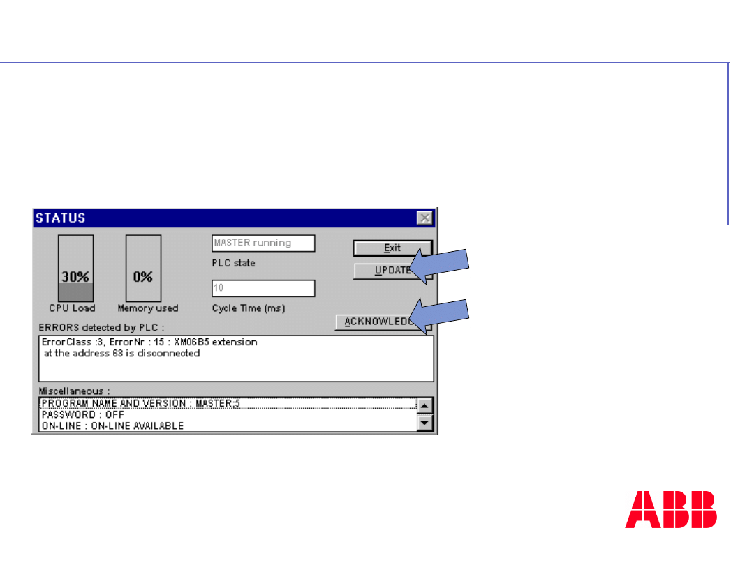
In the status window :
• The error can be
up dated by « UP
DATE » button
• The error can be
acknowledged by
«ACKNOWLEDGE »
button
Through Software AC31GRAF
©
A
B
B
C
o
n
tr
o
l
tr
a
in
in
g
P
a
g
e
-
9
8
-
A
C
3
1
4
0
&
5
0
s
e
ri
e
s
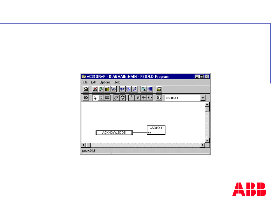
It is possible to acknowledge an error
when the function block « CS31QU » is
valided
In user program
©
A
B
B
C
o
n
tr
o
l
tr
a
in
in
g
P
a
g
e
-
9
9
-
A
C
3
1
4
0
&
5
0
s
e
ri
e
s
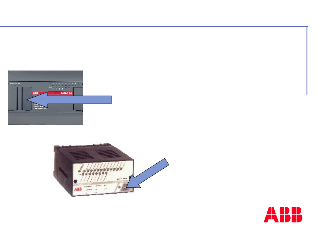
By restarting the central
unit and new
initialisation of CS31
bus
By action with test
button on the
remote unit (30
serie)
Only if the errors have been
corrected
Directly on the products
©
A
B
B
C
o
n
tr
o
l
tr
a
in
in
g
P
a
g
e
-
1
0
0
-
A
C
3
1
4
0
&
5
0
s
e
ri
e
s
Insert
image
here
- 9 -
Communicatio
n
ABB
Automation
©
A
B
B
C
o
n
tr
o
l
tr
a
in
in
g
P
a
g
e
-
1
0
1
-
A
C
3
1
4
0
&
5
0
s
e
ri
e
s
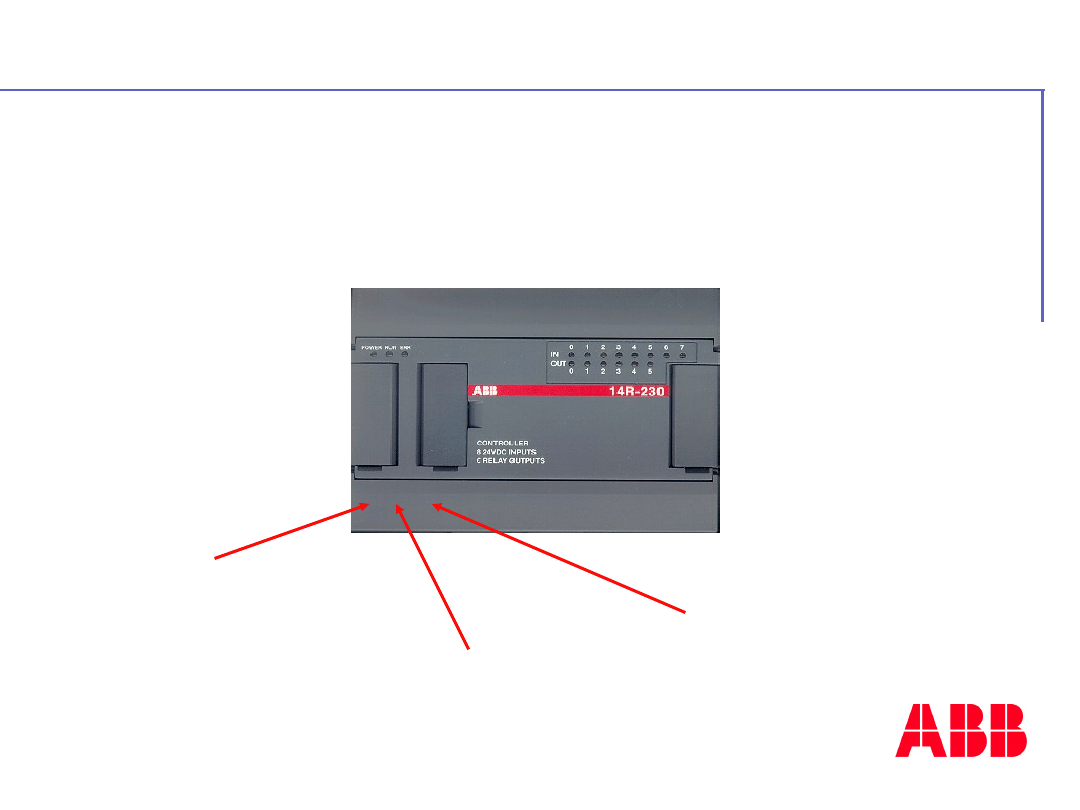
Three communication
protocols
Modbus
mode
ASCII mode
Programming
mode
With 40 & 50 series central units

©
A
B
B
C
o
n
tr
o
l
tr
a
in
in
g
P
a
g
e
-
1
0
2
-
A
C
3
1
4
0
&
5
0
s
e
ri
e
s
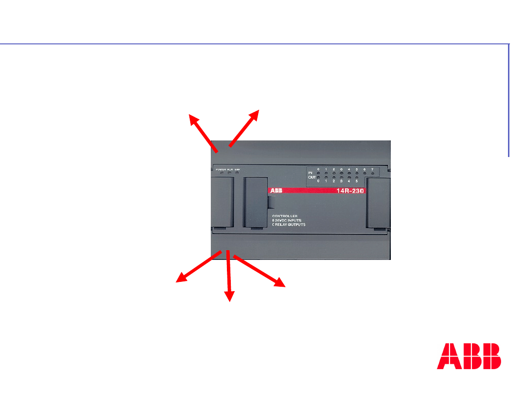
Incorporated in the 40 and 50
series central units
Advantages :
- It is known world-wide
- It is easier
- It is powerful
MODBUS protocol
©
A
B
B
C
o
n
tr
o
l
tr
a
in
in
g
P
a
g
e
-
1
0
3
-
A
C
3
1
4
0
&
5
0
s
e
ri
e
s
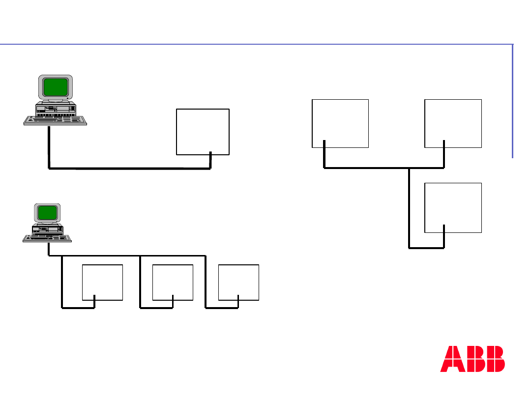
40 or 50
series
MODBUS protocol
RS232 line
50
series
MODBUS protocol
RS485 line
series
series
50
50
50 series
MODBUS protocol
RS485 line
50 series
50 series
Point to point connection with
a PC
Network connection between
CPUs
Network connection with a PC
Example of configuration :
©
A
B
B
C
o
n
tr
o
l
tr
a
in
in
g
P
a
g
e
-
1
0
4
-
A
C
3
1
4
0
&
5
0
s
e
ri
e
s
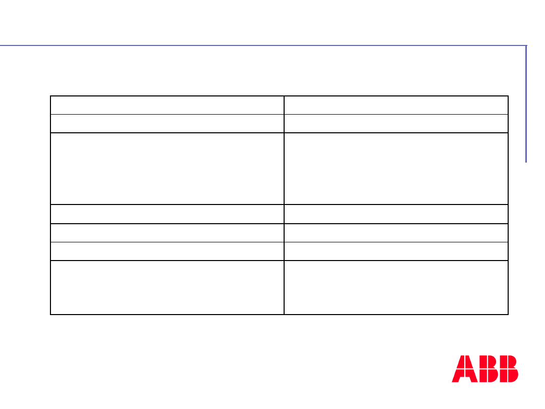
Support
RS232, RS485, optic fibers,...
Mode
RS485 half-duplex
Number of connection points
1 single master
max. 1 slave with RS232 interface
max. 31 slaves with RS485 interface
max. 255 slaves with repeaters
Protocol
MODBUS (master / slave)
Transmission control
CRC 16
Speed
up to 19 200 Bauds
Maximum length
on RS485:
1 200 m at 19 200 Bauds
1 500 m at 300 Bauds
Modbus protocol description

©
A
B
B
C
o
n
tr
o
l
tr
a
in
in
g
P
a
g
e
-
1
0
5
-
A
C
3
1
4
0
&
5
0
s
e
ri
e
s
•
Only with the black 07SK51 or
07SK53 cables
• Configure through AC31GRAF
Software
• Configure in user program
P.S.
The serial interface of the 40 and 50 series central
units have a factory setting Modbus configuration :
Mode: Modbus slave 1 unit
transmission speed: 9600 bauds
Number of stop bits: 1 / Number of data
bits : 8
Parity: None
Communication configuration
©
A
B
B
C
o
n
tr
o
l
tr
a
in
in
g
P
a
g
e
-
1
0
6
-
A
C
3
1
4
0
&
5
0
s
e
ri
e
s
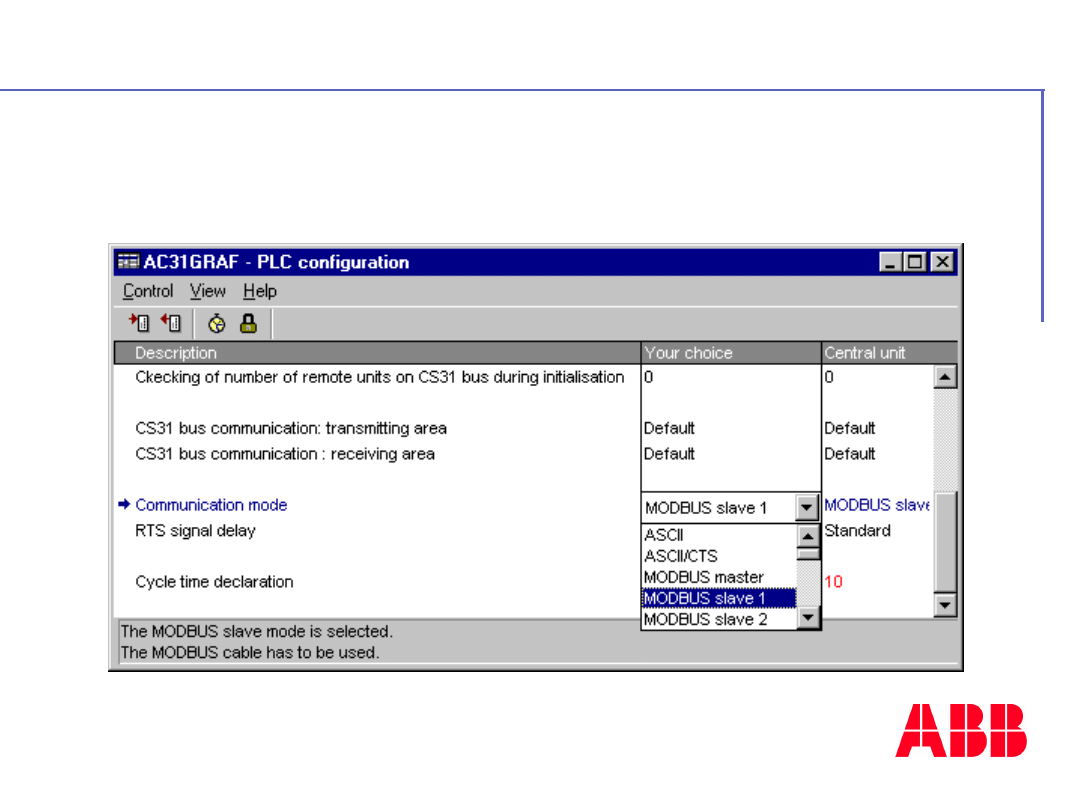
Through AC31GRAF Software
How configure the communication ?
©
A
B
B
C
o
n
tr
o
l
tr
a
in
in
g
P
a
g
e
-
1
0
7
-
A
C
3
1
4
0
&
5
0
s
e
ri
e
s
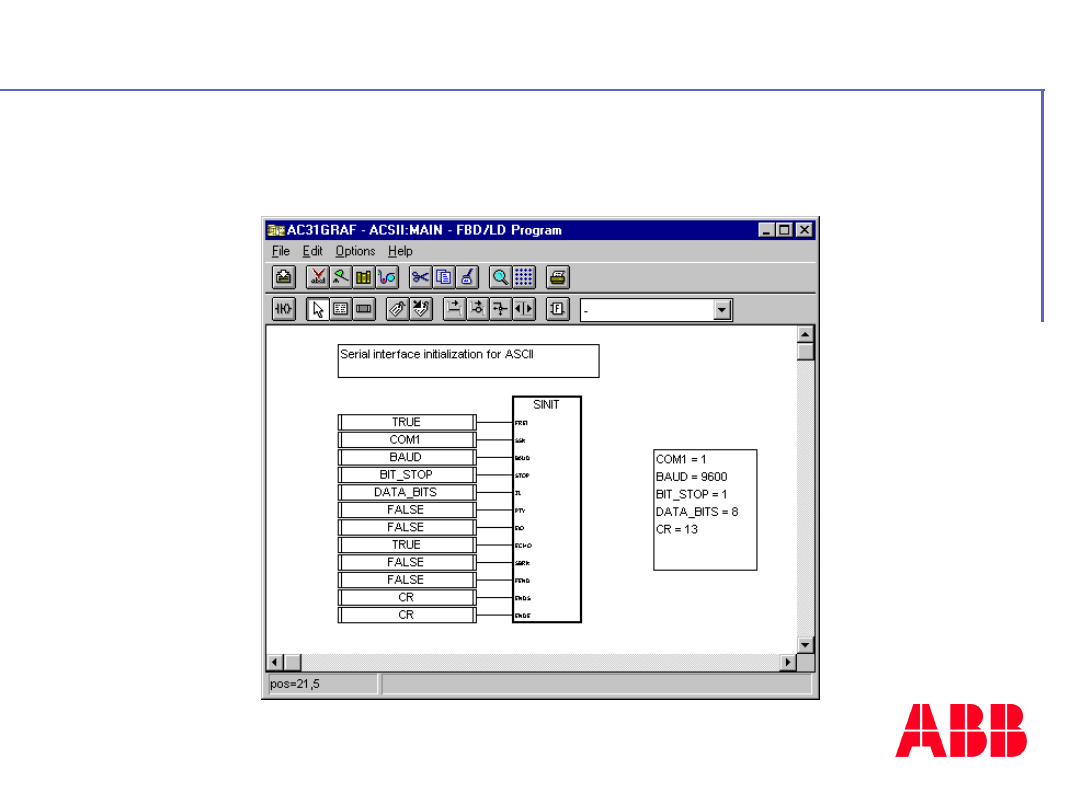
In user program ( With SINIT function
block)
How configure the communication ?

©
A
B
B
C
o
n
tr
o
l
tr
a
in
in
g
P
a
g
e
-
1
0
8
-
A
C
3
1
4
0
&
5
0
s
e
ri
e
s
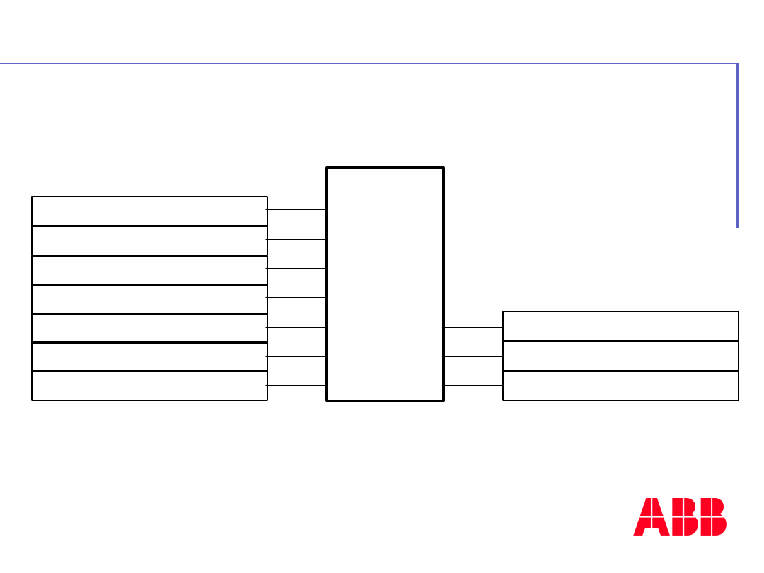
• Modbus slave central unit
A program isn’t required in central unit
.
• Modbus master central unit
The Modbus function enables sending data
read / write request to Modbus slaves
.
•
List of cross references
An exchange of Modbus data is realised in a
table defined by:
- the Modbus address of the first variable
- the list size = total number of variables in the
list
Modbus programming
©
A
B
B
C
o
n
tr
o
l
tr
a
in
in
g
P
a
g
e
-
1
0
9
-
A
C
3
1
4
0
&
5
0
s
e
ri
e
s
ERROR_CODE
ERROR
READY
%O62.00
6
992
TIME_2S
READ_BITS
SLAVE_1
READY
EADY
MODBUS
FREI
SLAV
FCT
TIME
ADDR
NB
DATA
RDY
ERR
ERN
Example of Modbus function block

©
A
B
B
C
o
n
tr
o
l
tr
a
in
in
g
P
a
g
e
-
1
1
0
-
A
C
3
1
4
0
&
5
0
s
e
ri
e
s
It enables exchanging text coded in ASCII,
between 40, 50 series central units and a
printer or a terminal fitted with an ASCII
interface.
• Using the
black
07SK51 or 07SK53 cable.
• It is necessary to configure the communication
parameters (Speed, Stop bits, data bits, parity,…. )
with the
SINIT
function block in the user program.
• Sending an ASCII message is done with the
SEND
function block in the user program.
• Receiving an ASCII message is done with the
REC
function block in the user program.
ASCII protocol

©
A
B
B
C
o
n
tr
o
l
tr
a
in
in
g
P
a
g
e
-
1
1
1
-
A
C
3
1
4
0
&
5
0
s
e
ri
e
s
This protocol uses the serial interface of the
central unit and is reserved for devices which
dispose of an ABB programming interface
• Using the
grey
07SK50 or 07SK52 cable.
• All variable values can be read or written by this
protocol without any configuration or any particular
program in the central units.
• The communication parameters are :
- 9600 bauds
- 8 data bits
- 1 stop bit
- No parity
Programming protocol
©
A
B
B
C
o
n
tr
o
l
tr
a
in
in
g
P
a
g
e
-
1
1
2
-
A
C
3
1
4
0
&
5
0
s
e
ri
e
s
Insert
image
here
- 9b -
MODBUS®
Master or
Slave via CS 31
connection
ABB
Automation
©
A
B
B
C
o
n
tr
o
l
tr
a
in
in
g
P
a
g
e
-
1
1
3
-
A
C
3
1
4
0
&
5
0
s
e
ri
e
s
MODBUS mode
CS31 Bus
mode
MODBUS
mode
ASCII
mode
Programming
mode
With 50 series central units
©
A
B
B
C
o
n
tr
o
l
tr
a
in
in
g
P
a
g
e
-
1
1
4
-
A
C
3
1
4
0
&
5
0
s
e
ri
e
s
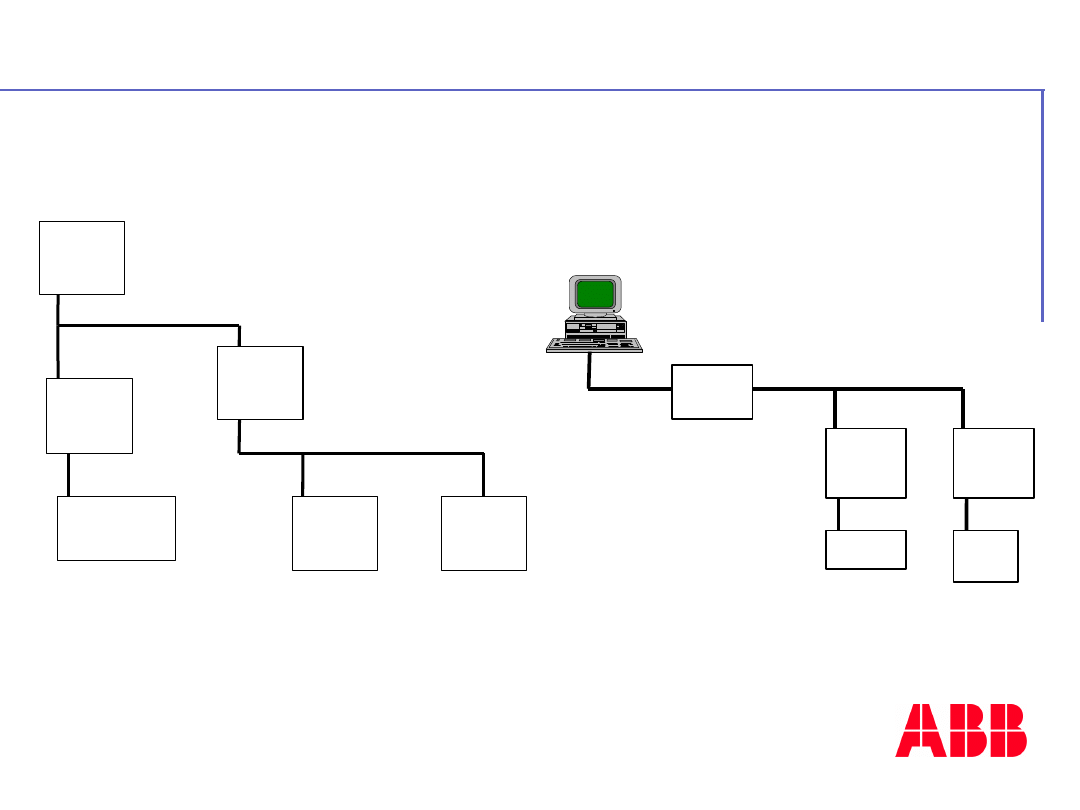
Examples of configuration :
MODBUS master
RS232
RS485
Converter
RS232/RS485
50
serie
MODBUS slave
50
serie
MODBUS slave
TC50
DRIVE
MODBUS master
MODBUS master
50 serie
50 serie
50 serie
MODBUS Master
MODBUS Slave
MODBUS Slave
MODBUS Master
50 serie
50 serie
MODBUS Slave
MODBUS Slave
TC50
Control panel
MODBUS Master
Network connection between
CPUs
Network connection with a PC
©
A
B
B
C
o
n
tr
o
l
tr
a
in
in
g
P
a
g
e
-
1
1
5
-
A
C
3
1
4
0
&
5
0
s
e
ri
e
s
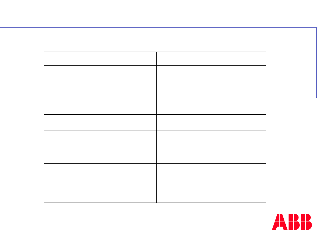
Protocol description
Support
CS31 Connection
Mode
Half-Duplex
Number of Connection points
1 Slave with RS485 interface
31 Slaves without repeater
255 Slaves with repeater
Protocol
MODBUS Master or Slave
Transmission control
CRC 16
Speed
Up to 115 200 Bauds
Maximum length
On RS485 :
600 m at 76 800 Bauds
1 200 m at 19 200 Bauds
©
A
B
B
C
o
n
tr
o
l
tr
a
in
in
g
P
a
g
e
-
1
1
6
-
A
C
3
1
4
0
&
5
0
s
e
ri
e
s
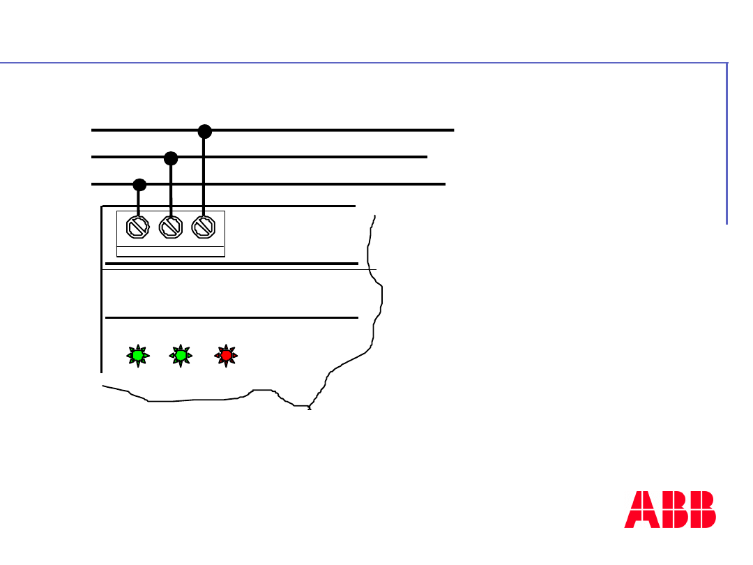
Connections
BUS2 BUS1 Sh
POWER RUN ERR
Shield
D1 +
D1 -
You can use the 07SK53 cable to
connect the Central unit on the network
RS485
RS485 Network
©
A
B
B
C
o
n
tr
o
l
tr
a
in
in
g
P
a
g
e
-
1
1
7
-
A
C
3
1
4
0
&
5
0
s
e
ri
e
s
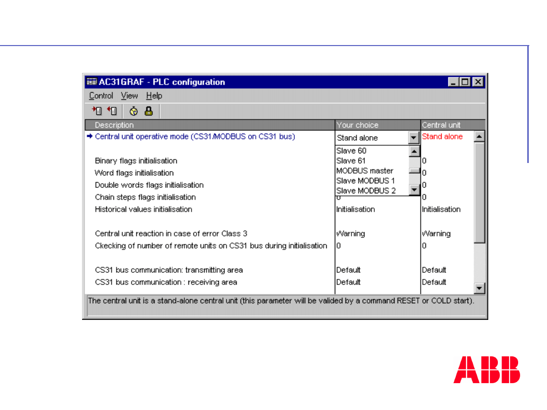
Configurations
In the PLC configuration window in
AC31GRAF Software

©
A
B
B
C
o
n
tr
o
l
tr
a
in
in
g
P
a
g
e
-
1
1
8
-
A
C
3
1
4
0
&
5
0
s
e
ri
e
s
- Mode:
Standalone
- Transmission speed :
19 200 Bauds
- Number of stop bits :
1
- Number of data bits :
8
- Parity :
None
Default parameters for the CS31
interface
COM 2

©
A
B
B
C
o
n
tr
o
l
tr
a
in
in
g
P
a
g
e
-
1
1
9
-
A
C
3
1
4
0
&
5
0
s
e
ri
e
s
Configurations
Operative mode parameter
:
Constant system KW00.00: MODBUS
Master
or Slave
Meaning of the value of KW00.00:
KW00.00 = MODBUS
Slave address + 1100
Example
: MODBUS
Slave address N°5
KW00.00 = 5 + 1100 = 1105
©
A
B
B
C
o
n
tr
o
l
tr
a
in
in
g
P
a
g
e
-
1
2
0
-
A
C
3
1
4
0
&
5
0
s
e
ri
e
s
Configurations
Configure the CS31 port parameters by user
program
SINIT
FREI
SSK
BAUD
STOP
ZL
PTY
E/O
ECHO
SBRK
FEND
ENDS
ENDE
TRUE
COM_2
SPEED_BAUDS
ONE_BIT_STOP
DATA_BITS_8
FALSE
FALSE
FALSE
FALSE
FALSE
ENDS
ENDE
Use the
SINIT block
in AC31GRAF Software
SSK parameter
=
COM2
BAUD parameter
=
Speed
9600
write directly
9600
19200
write directly
19200
33600
is written through Code
44
38400
is written through Code
38
57600
is written through Code
25
75000
is written through Code
19
76800
is written through Code
18
115200
is written through Code
12
125000
is written through Code
11
187500
is written through Code
7
375000
is written through Code
3
750000
is written through Code
1
©
A
B
B
C
o
n
tr
o
l
tr
a
in
in
g
P
a
g
e
-
1
2
1
-
A
C
3
1
4
0
&
5
0
s
e
ri
e
s
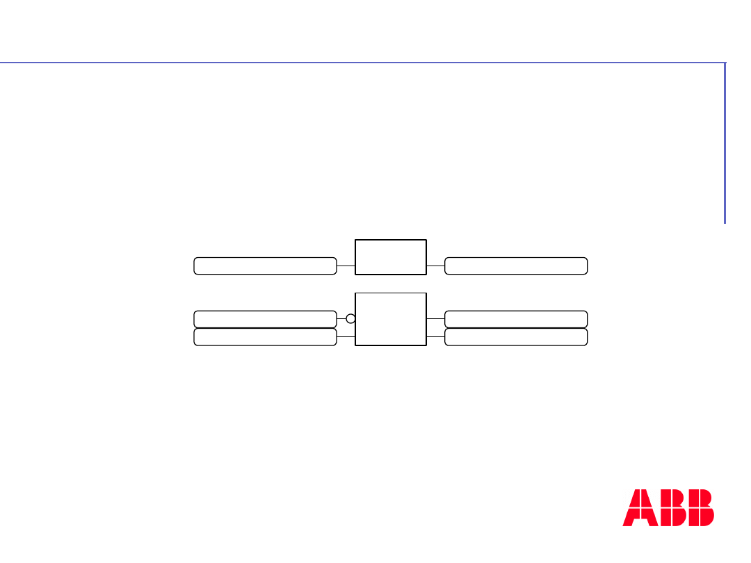
Default detection
The binary flag M255.07 can be used as a
watch-dog for the MODBUS
Slave on the
CS31 bus
M255.07 flag is set to 1 when
the slave sends answer to the
master
%M255.07
TON
IN
PT
Q
ET
TIME_OUT
VALUE
%M255.07
=R
%M255.07
ALARM
©
A
B
B
C
o
n
tr
o
l
tr
a
in
in
g
P
a
g
e
-
1
2
2
-
A
C
3
1
4
0
&
5
0
s
e
ri
e
s
Insert
image
here
- 10 -
MODBUS
Coupler
07KP53

©
A
B
B
C
o
n
tr
o
l
tr
a
in
in
g
P
a
g
e
-
1
2
3
-
A
C
3
1
4
0
&
5
0
s
e
ri
e
s
Advantages with coupler solution
Fast response time
Fast response time
High speed communication : up to 115 KBauds
Concentrate data’s inside the coupler, to reduce
the number of cycle time necessary to interrogate
all MODBUS slaves
Increasing communication capacities
Increasing communication capacities
2 additional interfaces
Let the serial line free on CPU, for programming
mode or for ASCII communication (printer, bare
code,modems…)

©
A
B
B
C
o
n
tr
o
l
tr
a
in
in
g
P
a
g
e
-
1
2
4
-
A
C
3
1
4
0
&
5
0
s
e
ri
e
s
Advantages with coupler solution
Easy installation
Easy installation
In slave MODBUS mode, automatic detection of
polarity and speed baud.
Integrated end resistances for impedance
adaptation
New Features and applications
New Features and applications
Possibility to make redundancy of information
Asynchronous Mode
Extend present applications (Minimum 3.0
Version on CPU)

©
A
B
B
C
o
n
tr
o
l
tr
a
in
in
g
P
a
g
e
-
1
2
5
-
A
C
3
1
4
0
&
5
0
s
e
ri
e
s
Characteristics
2 independent
2 independent
MODBUS
MODBUS
communication ports
communication ports
Master or Slave MODBUS mode on
Master or Slave MODBUS mode on
each port
each port
High speed (up to 115200 bauds)
High speed (up to 115200 bauds)
RS485 ( Connectors ) and RS232 ( Min
RS485 ( Connectors ) and RS232 ( Min
DIN8 )
DIN8 )
Synchronous or / and asynchronous
Synchronous or / and asynchronous
mode (possibility to mixed both modes)
mode (possibility to mixed both modes)
Power supply provide by the CPU
Power supply provide by the CPU
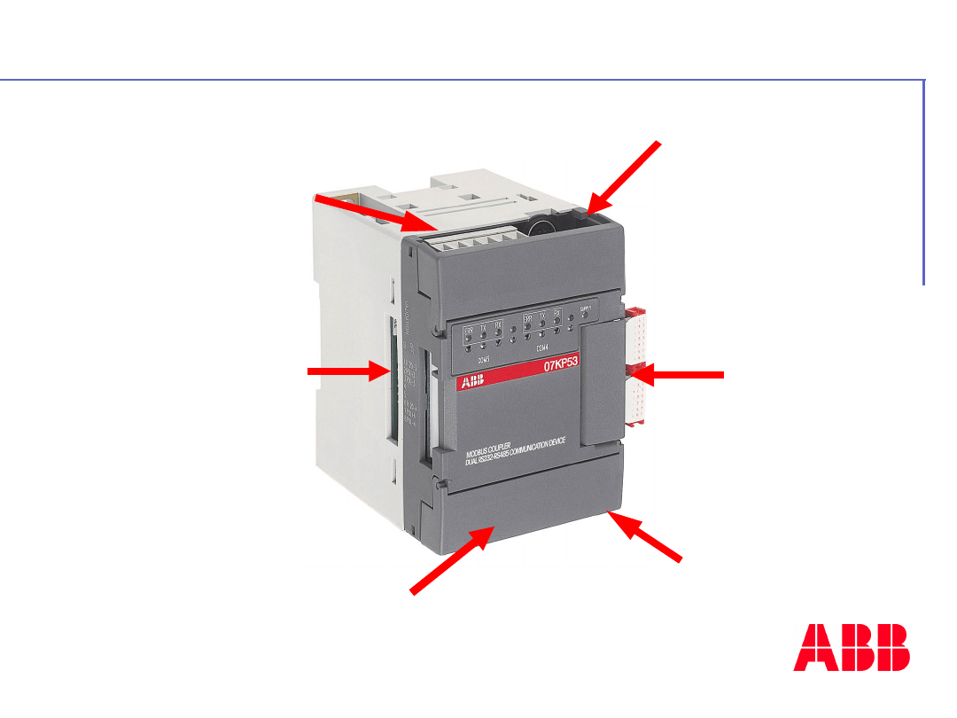
©
A
B
B
C
o
n
tr
o
l
tr
a
in
in
g
P
a
g
e
-
1
2
6
-
A
C
3
1
4
0
&
5
0
s
e
ri
e
s
Description
(COM 3)
communicatio
n port
Min-DIN8,
RS232
Dip-switches
(COM 4)
communicatio
n port
Min-DIN8,
RS232
(COM3)
communication
port RS485
connection
(COM4)
communication
port on
RS485 connection
Connection
with the
CPU

©
A
B
B
C
o
n
tr
o
l
tr
a
in
in
g
P
a
g
e
-
1
2
7
-
A
C
3
1
4
0
&
5
0
s
e
ri
e
s
Dip-switches and LED's
The Dip-switches are used to
set the polarity of bus (only
in Master mode) and to
connect an internal
resistance (end of bus =120
).
LED ’s
indication
ERR
TX
RX
COM3
ERR
TX
RX
COM4
SUPPLY
Power
supply
Error on
communication
TX and
RX
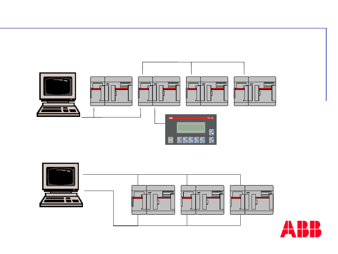
©
A
B
B
C
o
n
tr
o
l
tr
a
in
in
g
P
a
g
e
-
1
2
8
-
A
C
3
1
4
0
&
5
0
s
e
ri
e
s
Configurations example
Configuration with
redundancy
Configuration with MODBUS master and slaves

©
A
B
B
C
o
n
tr
o
l
tr
a
in
in
g
P
a
g
e
-
1
2
9
-
A
C
3
1
4
0
&
5
0
s
e
ri
e
s
Synchronous & Asynchronous Mode
Synchronous mode
Synchronous mode
Coupler used as CPU additional com port : one
request on each the cycle time
Asynchronous mode
Asynchronous mode
Coupler concentrate in a table all data from the
interrogated slaves independently from cycle
time, CPU need only a cycle time to get all the
table.
Response time
:
Synchronous communication mode
:
1 cycle automate + 5 character time
+200µs+10µs/word
Asynchronous communication mode
:
5 character time +200µs+10µs/word
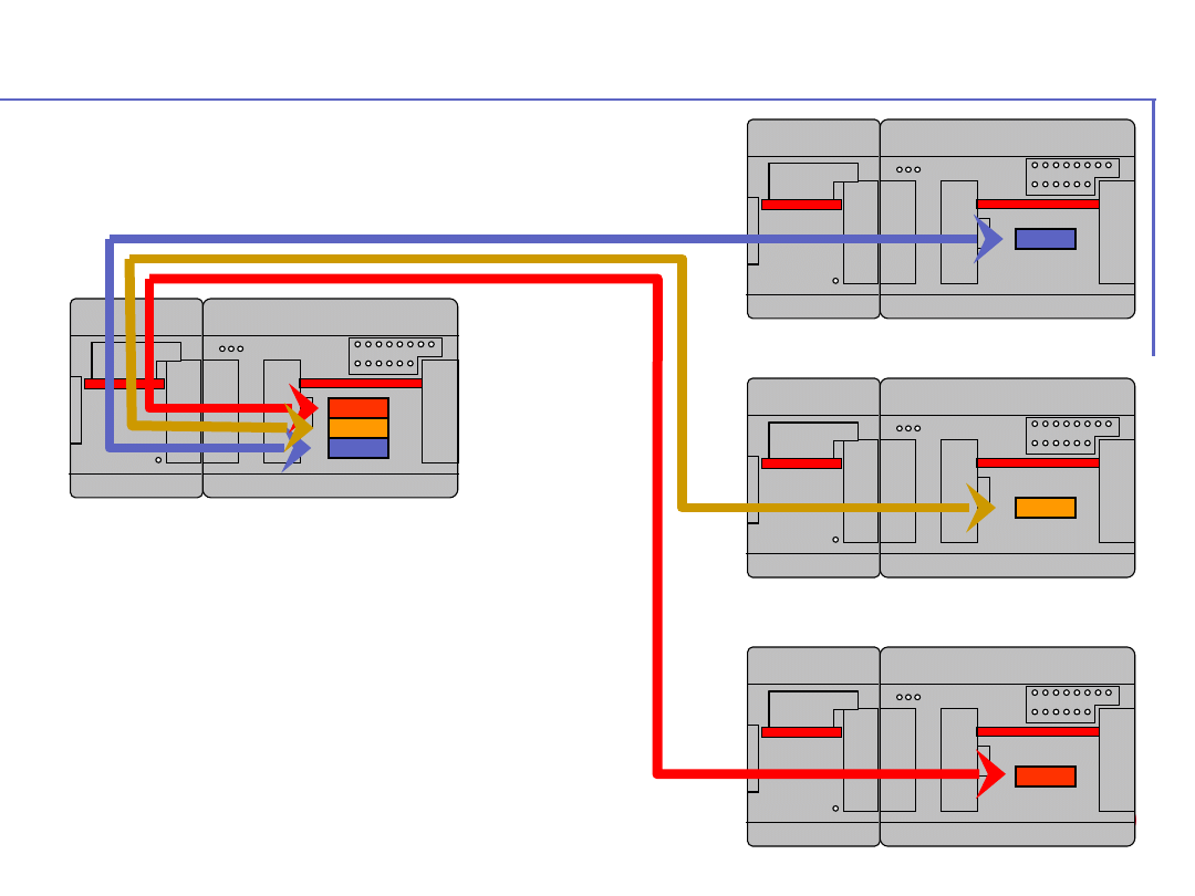
©
A
B
B
C
o
n
tr
o
l
tr
a
in
in
g
P
a
g
e
-
1
3
0
-
A
C
3
1
4
0
&
5
0
s
e
ri
e
s
Synchronous mode
Step 1, First cycle time
Step 2, Second cycle time
Step 3, Third cycle time
Example with 16 slaves,
115Kbauds : 916 ms
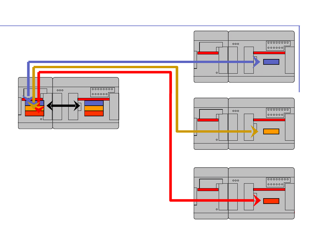
©
A
B
B
C
o
n
tr
o
l
tr
a
in
in
g
P
a
g
e
-
1
3
1
-
A
C
3
1
4
0
&
5
0
s
e
ri
e
s
Asynchronous mode
Fast request by coupler
(depending on slave
response time)
Data-backup from coupler
to CPU, 1 cycle time
Example with 16 slaves, 115Kbds : 436
ms (time divided by 2, compare to
synchronous mode)
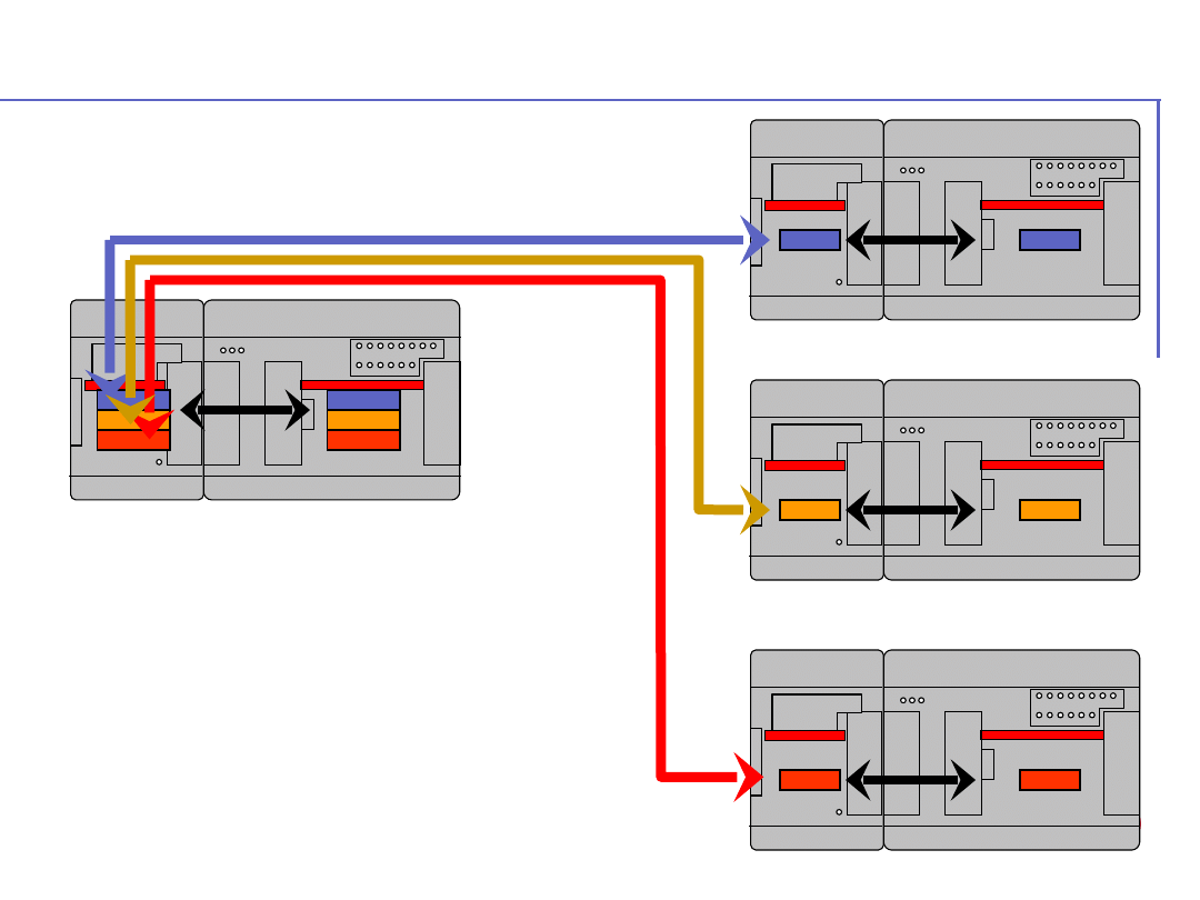
©
A
B
B
C
o
n
tr
o
l
tr
a
in
in
g
P
a
g
e
-
1
3
2
-
A
C
3
1
4
0
&
5
0
s
e
ri
e
s
Asynchronous Ultra fast mode
Fast request by coupler
Data-backup from coupler
to CPU, 1 cycle time
Slave coupler request
Example with 16 slaves, 115Kbds : 219
ms (time divided by 4, compare to
synchronous mode)
©
A
B
B
C
o
n
tr
o
l
tr
a
in
in
g
P
a
g
e
-
1
3
3
-
A
C
3
1
4
0
&
5
0
s
e
ri
e
s
Guide to initialise and communicate
Initialisation :
MODMASKT
coupler
configuration
Table : Master,
speed, time out
Communication :
1 MODMASTK by
Slave
Coupler on
master CPU
Coupler on
Slaves CPU
Asynchronous
Synchronous
Asynchronous
(fast mode)
Initialisation :
MODMASKT
coupler
configuration
Table : Master,
speed, time out,
and request
Communication :
only 1
MODMASTK
Initialisation :
MODMASKT
coupler
configuration
Table : Master,
speed, time out,
and request
Communication :
only 1
MODMASTK
Initialisation :
MODMASKT
coupler
configuration
Table : Slave
number
Initialisation :
MODMASKT
coupler
configuration
Table : Slave
number
Initialisation :
MODMASKT coupler
configuration
Table : Slave
number,
request to
keep data
Communication :
only 1
MODMASTK

©
A
B
B
C
o
n
tr
o
l
tr
a
in
in
g
P
a
g
e
-
1
3
4
-
A
C
3
1
4
0
&
5
0
s
e
ri
e
s
Configuration table
Parameter zone
Parameter zone
Constant 0 = 1100 to 1355 (1100 master, 1101 slave 1, 1102 slave
2…)
Constant 1 = Communication speed (see next slide)
Constant 2 = Set the delay between rising edge of RTS and start of
emission
(used for modems, this counter is managed by unit of
10ms)
Constant 3 = Set timeout communication (in ms)
Request zone
Request zone
Constant 4 = Slave number for the first request (1 to 255)
Constant 5 = MODBUS function
(1,2 : read bits 3,4 : Read words 15,16 : Write words)
Constant 6 = MODBUS address of the data in the slave
Constant 7 = Number of data requested (< 120 words or 1920 bits)
First request
Second request
Constant 8 = Slave number for the 2
nd
request (1 to 255)
Constant 9 = MODBUS function (1, 2, 3, 4, 5, 15, 16)
Constant 10 = MODBUS address of the data in the slave
Constant 11 = Number of data requested (< 120 words or 1920 bits)
…
Repeat the same for the 58 others requests

©
A
B
B
C
o
n
tr
o
l
tr
a
in
in
g
P
a
g
e
-
1
3
5
-
A
C
3
1
4
0
&
5
0
s
e
ri
e
s
Memory limitations
Max number of request :
60 for each com
port
Max size for each request : 120 words.
Max size of result table :
256 words for each
com port
Example of the limits configuration
(supposing equal repartition):
- 60 requests of 4 words each
- 2 requests of 120 words each
COM3 result table can overlap COM4 result table.
Maximum of 512 words : in that case COM4 is used
only with synchronous mode.
©
A
B
B
C
o
n
tr
o
l
tr
a
in
in
g
P
a
g
e
-
1
3
6
-
A
C
3
1
4
0
&
5
0
s
e
ri
e
s
Communication speed
Speed (BAUD)
code
2400
2400
4800
4800
9600
9600
19200
19200
33600
44
38400
38
57600
25
75000
19
76800
18
115200
12
All the communication speed available with
coupler, with the corresponding codes
©
A
B
B
C
o
n
tr
o
l
tr
a
in
in
g
P
a
g
e
-
1
3
7
-
A
C
3
1
4
0
&
5
0
s
e
ri
e
s
Coupler initialisation & communication
Use MODMASTK (AC31GRAF) or
Use MODMASTK (AC31GRAF) or
MODMASTW (907AC1131)
MODMASTW (907AC1131)
function
function
blocks
blocks
Initialisation : MODMASTK or MODMASTW
function blocks are used to initialise the coupler at
first : Initialisation of the communication ports
COM3 and COM4 (master or slave, speed, RTS
signal delay, time out)
Communication : MODMASTK or
MODMASTW function blocks are used to
communicate between the CPU and the coupler
(write or read data).
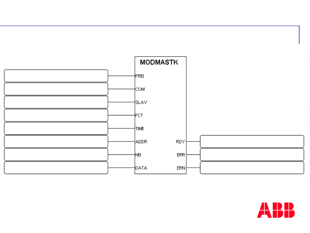
©
A
B
B
C
o
n
tr
o
l
tr
a
in
in
g
P
a
g
e
-
1
3
8
-
A
C
3
1
4
0
&
5
0
s
e
ri
e
s
Coupler initialisation
Parameter for coupler initialisation
Parameter for coupler initialisation
Activation with a rising edge
Communication port : 3 or 4
256 for COM3, 257 for COM4
MODBUS function write word
(16)
Time out in milliseconds
ADDR : 30000 for COM3, 30244 for COM4
MODBUS address of configuration
Number of word used 1 to 120
1
rst
constant of the configuration
table
MODMASTK function ready
Error with the function
Error number
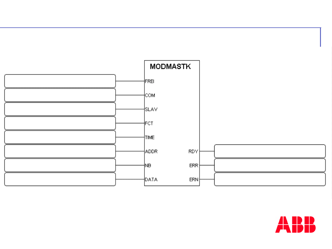
©
A
B
B
C
o
n
tr
o
l
tr
a
in
in
g
P
a
g
e
-
1
3
9
-
A
C
3
1
4
0
&
5
0
s
e
ri
e
s
Coupler communication
Parameter for communication
Parameter for communication
Communication port : 3 or 4
256 for COM3, 257 for COM4
MODBUS function Read or
Write
Time out in milliseconds
ADDR : 31000 for COM3, 31256 for COM4
MODBUS data address
Number of words used 1 to 120
First variable of data table in
CPU
Activation with a rising edge
MODMASTK function ready
Error with the function
Error number
* If COM4 is used in synchronous mode, the number of
words used for COM3 can be expended to 512.
©
A
B
B
C
o
n
tr
o
l
tr
a
in
in
g
P
a
g
e
-
1
4
0
-
A
C
3
1
4
0
&
5
0
s
e
ri
e
s
Insert
image
here
- 11 -
TC 50 & TC50-
2
ABB
Automation
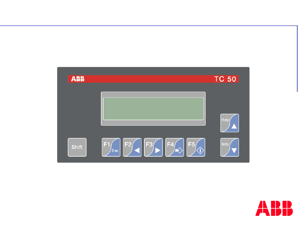
©
A
B
B
C
o
n
tr
o
l
tr
a
in
in
g
P
a
g
e
-
1
4
1
-
A
C
3
1
4
0
&
5
0
s
e
ri
e
s
Control panel TC50
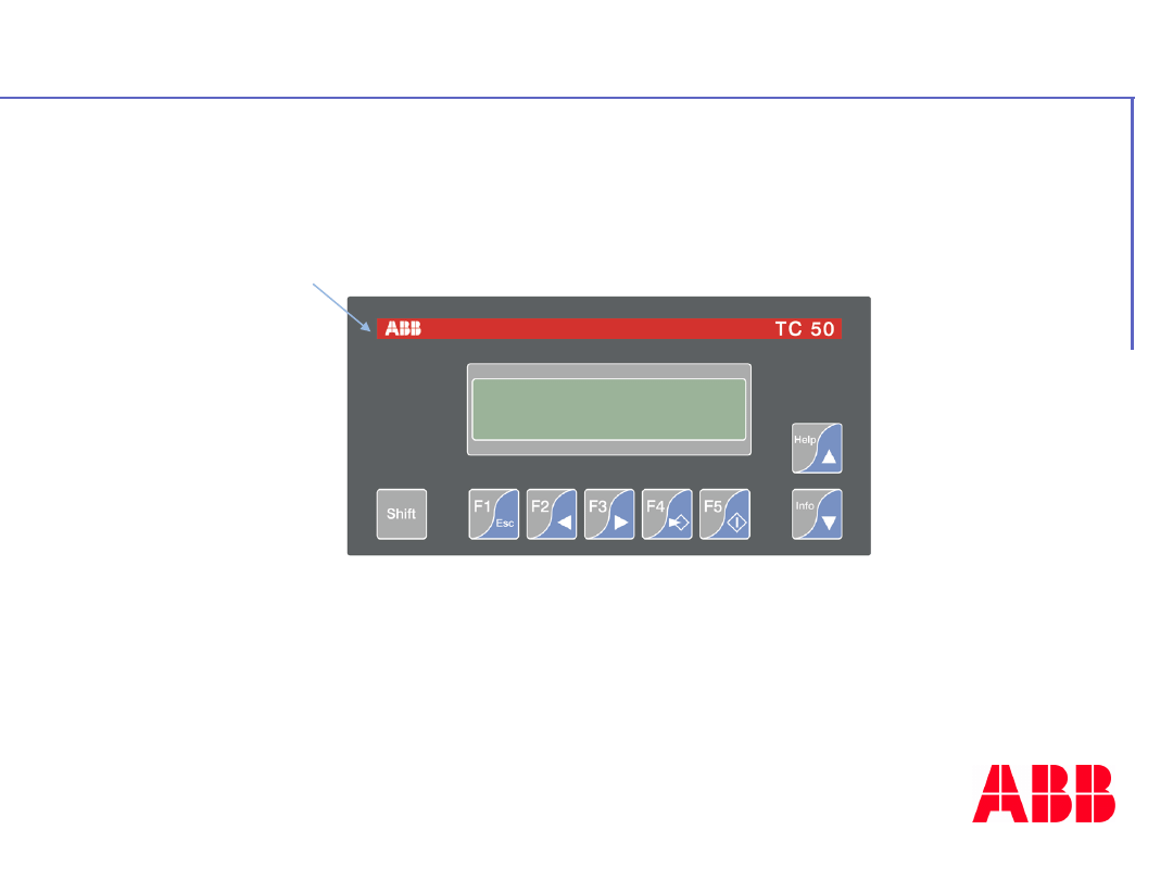
©
A
B
B
C
o
n
tr
o
l
tr
a
in
in
g
P
a
g
e
-
1
4
2
-
A
C
3
1
4
0
&
5
0
s
e
ri
e
s
Description
ABB design
External (W x H x D mm) = 166 x 86
x41
Cut-out size (W x H mm) = 157 x 77
Power supply = 24Vdc

©
A
B
B
C
o
n
tr
o
l
tr
a
in
in
g
P
a
g
e
-
1
4
3
-
A
C
3
1
4
0
&
5
0
s
e
ri
e
s
2 lines of 20 characters
128 pages
8 variables per pages
128 alarm / help texts
5 customisable key functions
IP 65 front unit protection
Characteristics
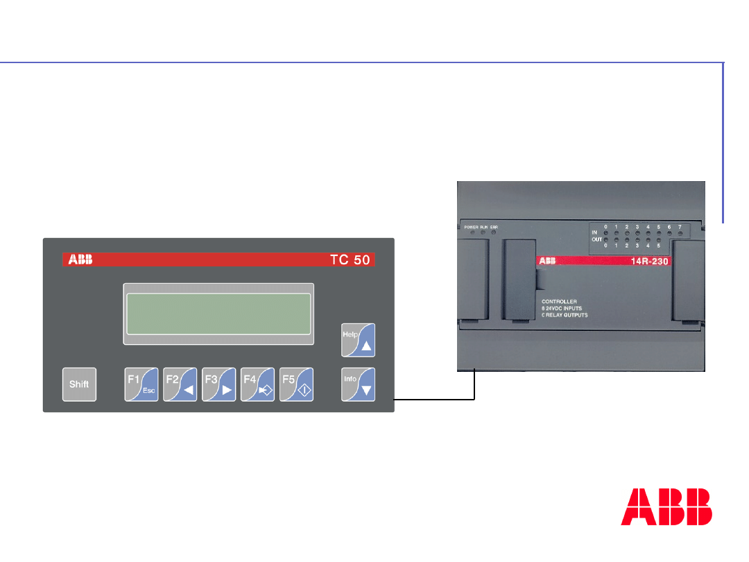
©
A
B
B
C
o
n
tr
o
l
tr
a
in
in
g
P
a
g
e
-
1
4
4
-
A
C
3
1
4
0
&
5
0
s
e
ri
e
s
How to connect the TC50-1?
RS232
MODBU
S
TC50-1 version
RS232
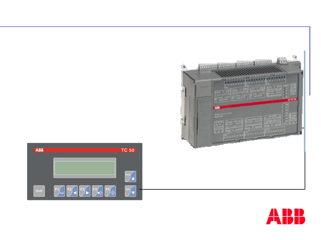
©
A
B
B
C
o
n
tr
o
l
tr
a
in
in
g
P
a
g
e
-
1
4
5
-
A
C
3
1
4
0
&
5
0
s
e
ri
e
s
How to connect the TC50-1?
RS232
Modbus protocol
With
KT94
TC50-1 version
RS232
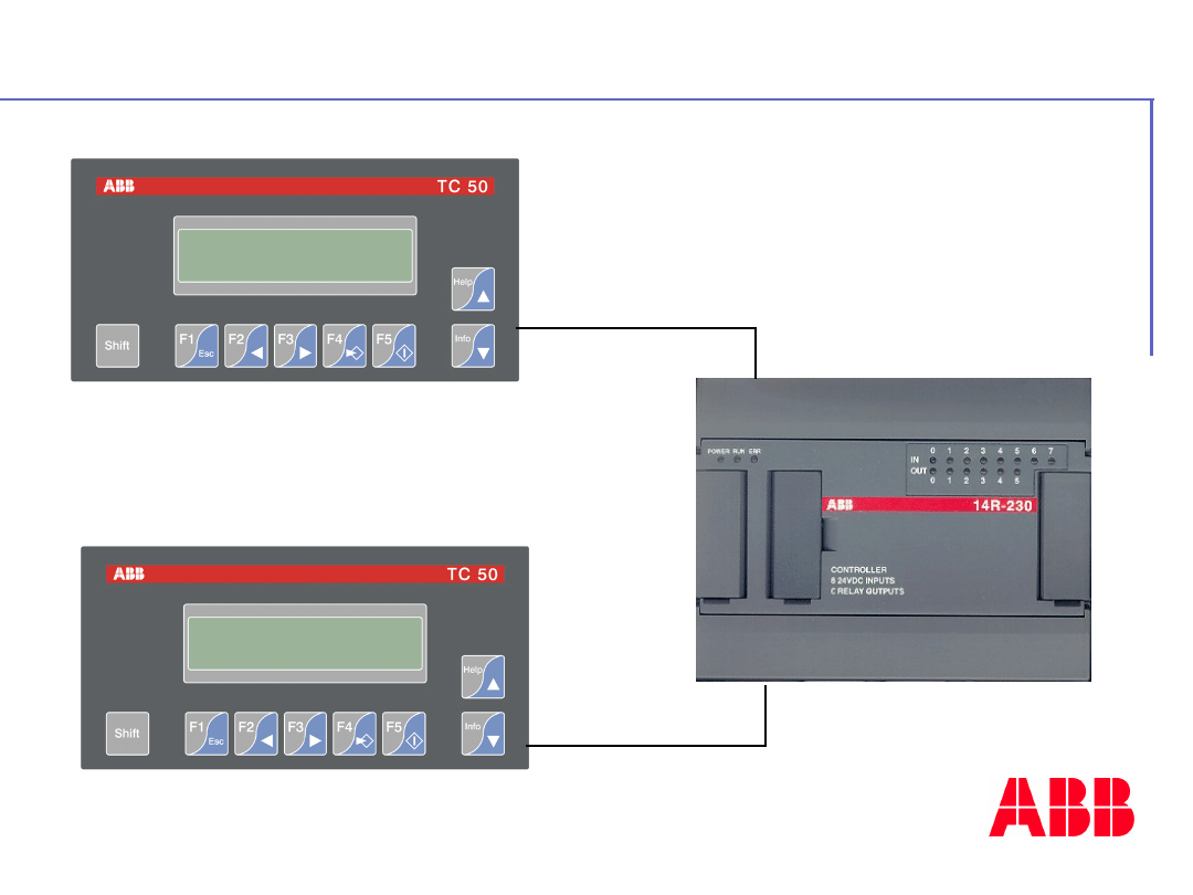
©
A
B
B
C
o
n
tr
o
l
tr
a
in
in
g
P
a
g
e
-
1
4
6
-
A
C
3
1
4
0
&
5
0
s
e
ri
e
s
How to connect the TC50-2?
RS485
MODBU
S
TC50-2 version
RS232/RS485
RS232
MODBU
S
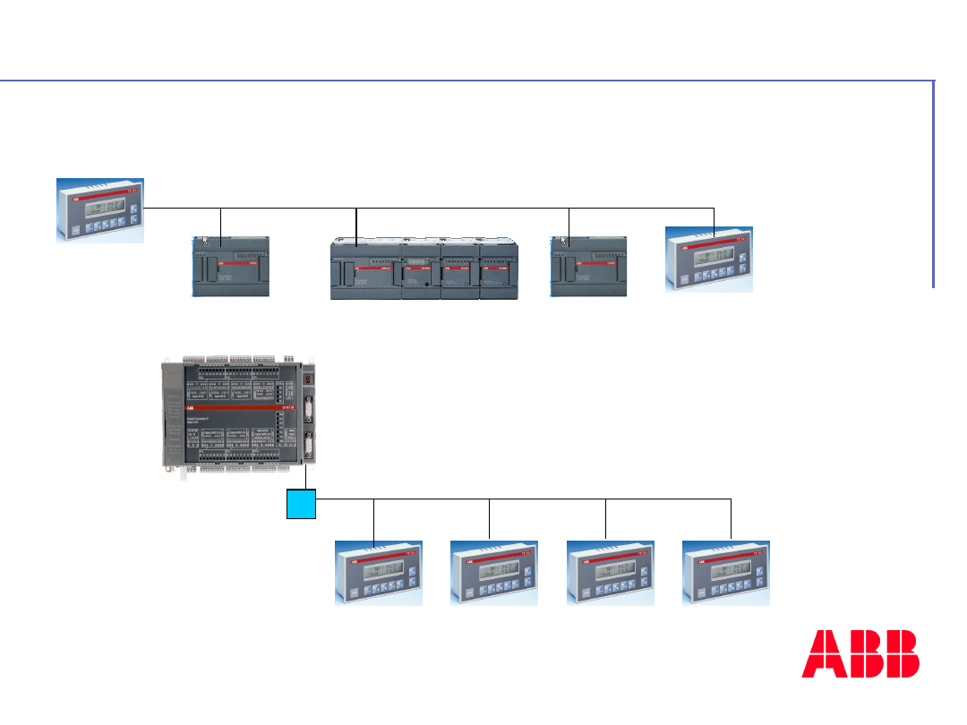
©
A
B
B
C
o
n
tr
o
l
tr
a
in
in
g
P
a
g
e
-
1
4
7
-
A
C
3
1
4
0
&
5
0
s
e
ri
e
s
Example of applications TC50-2?
MODBUS
MODBUS

©
A
B
B
C
o
n
tr
o
l
tr
a
in
in
g
P
a
g
e
-
1
4
8
-
A
C
3
1
4
0
&
5
0
s
e
ri
e
s
Control panel for all CS31 central units
(MODBUS or programming)
Programming software on Windows
Programming software available in 5 languages
(English, French, German, Italian, Spanish)
Texts can also be programmed in 5 languages
Advantages
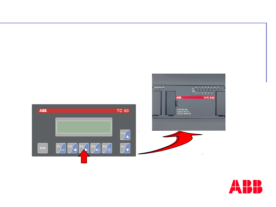
©
A
B
B
C
o
n
tr
o
l
tr
a
in
in
g
P
a
g
e
-
1
4
9
-
A
C
3
1
4
0
&
5
0
s
e
ri
e
s
Process control with key function
What can we do with the TC50?
1/
push
2 /
transfer to
CPU which
reacts
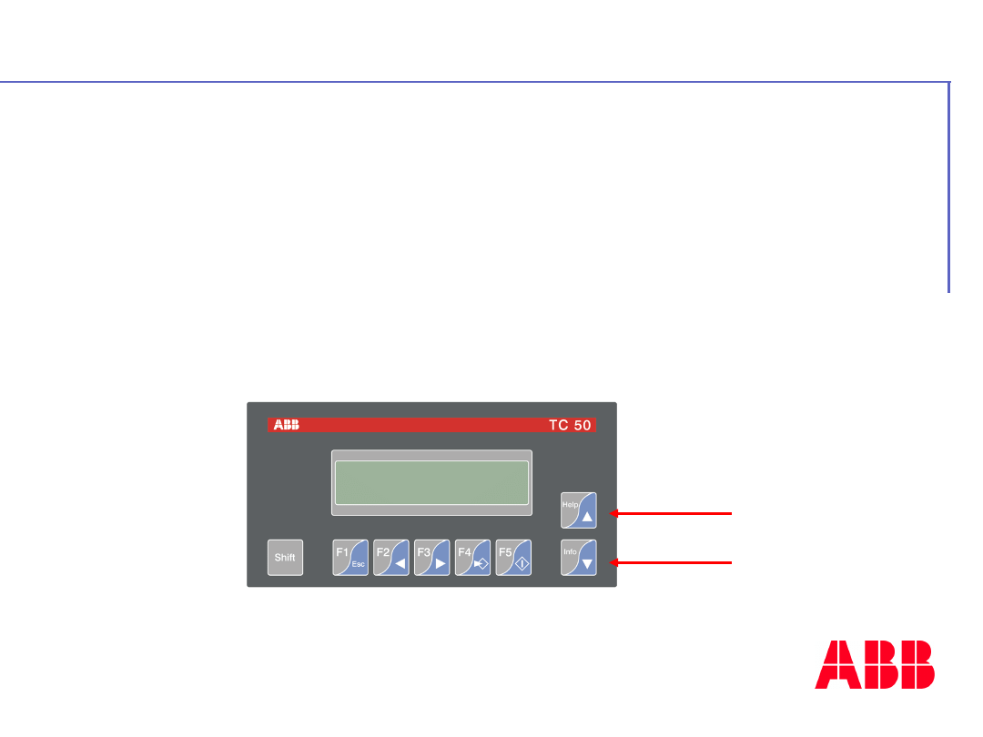
©
A
B
B
C
o
n
tr
o
l
tr
a
in
in
g
P
a
g
e
-
1
5
0
-
A
C
3
1
4
0
&
5
0
s
e
ri
e
s
Process control with key function
Sequences per pages
What can we do with the TC50?
Up
Dow
n
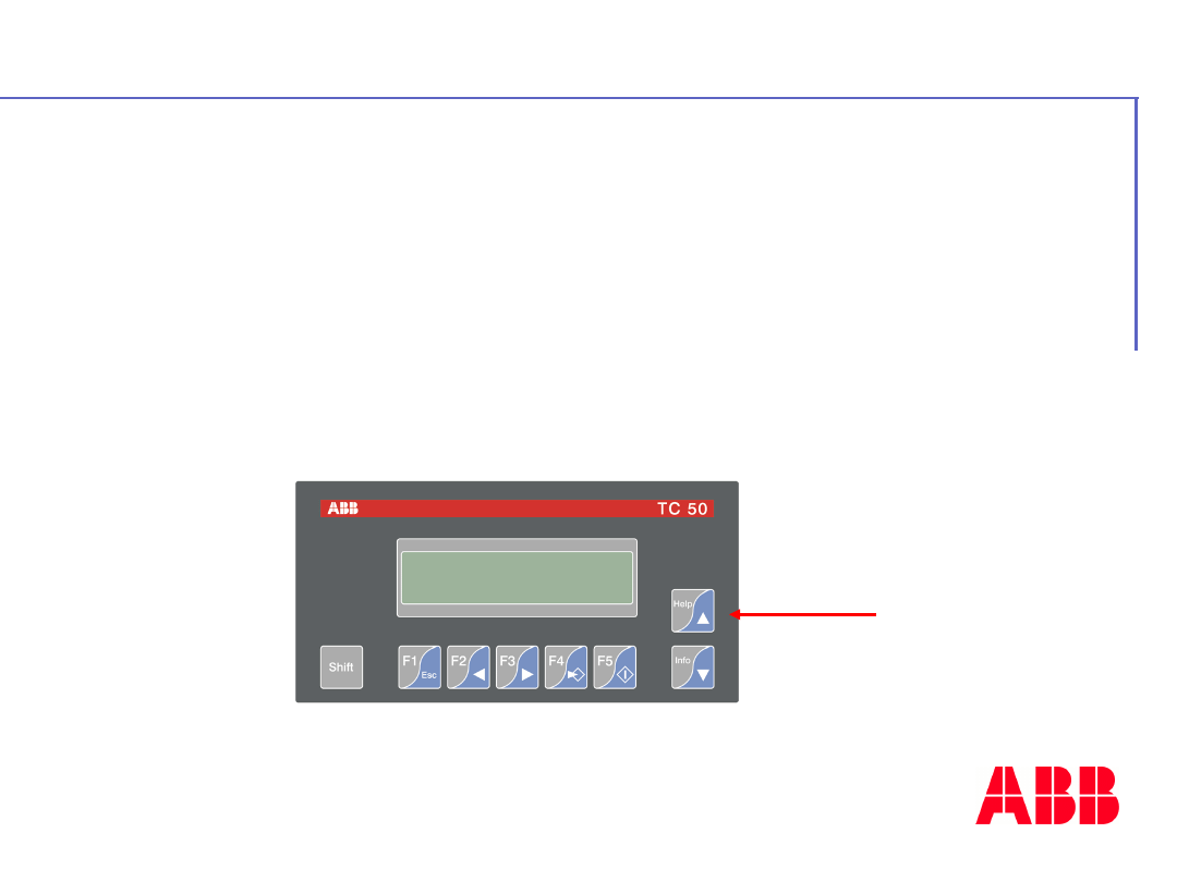
©
A
B
B
C
o
n
tr
o
l
tr
a
in
in
g
P
a
g
e
-
1
5
1
-
A
C
3
1
4
0
&
5
0
s
e
ri
e
s
Process control with key function
Sequences per pages
Alarms with help messages
What can we do with the TC50?
Help
Alarm
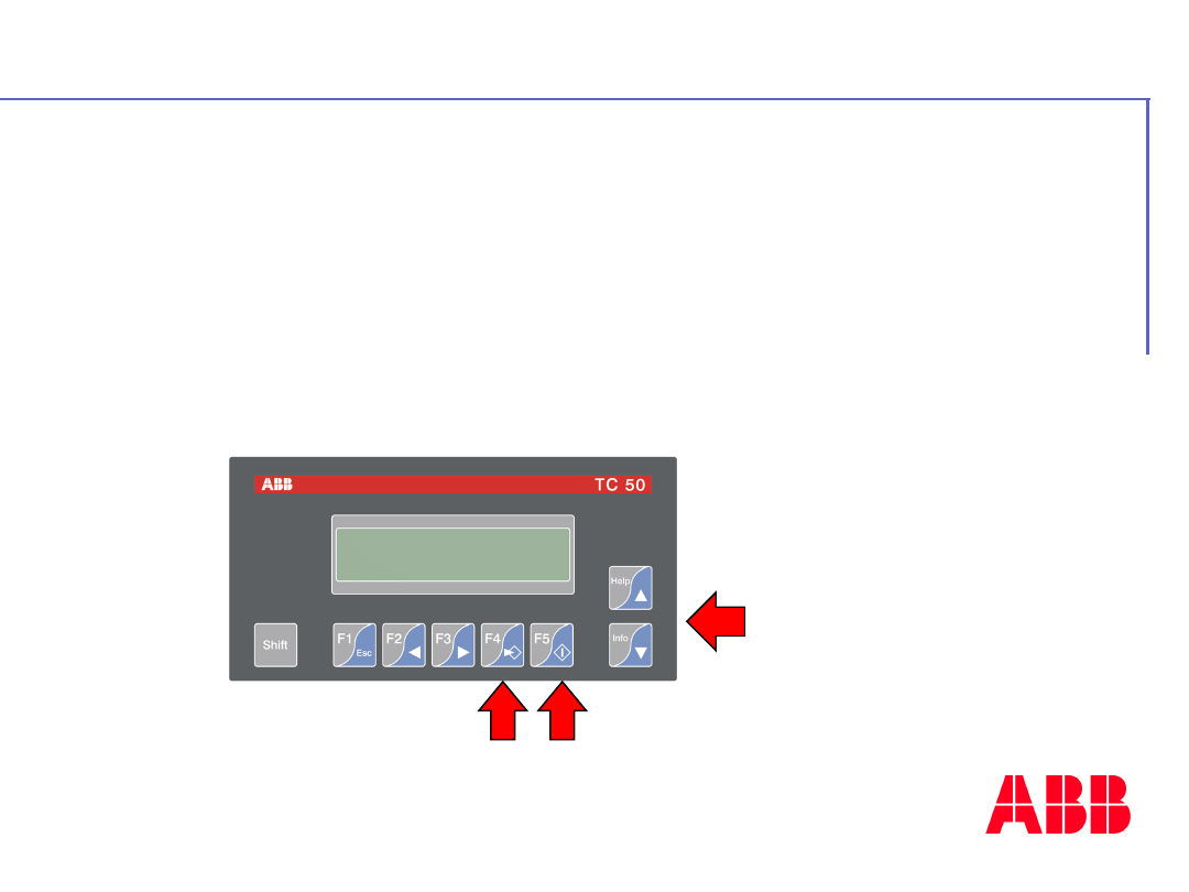
©
A
B
B
C
o
n
tr
o
l
tr
a
in
in
g
P
a
g
e
-
1
5
2
-
A
C
3
1
4
0
&
5
0
s
e
ri
e
s
Process control with key function
Sequences per pages
Alarms with help messages
Value modifications :
What can we do with the TC50?
1 3
2
1
value setting
2
modification
with up and
down
3
validation

©
A
B
B
C
o
n
tr
o
l
tr
a
in
in
g
P
a
g
e
-
1
5
3
-
A
C
3
1
4
0
&
5
0
s
e
ri
e
s
With TCWIN (for Windows 95, 98 or NT)
programming softwares
TC50 programming
©
A
B
B
C
o
n
tr
o
l
tr
a
in
in
g
P
a
g
e
-
1
5
4
-
A
C
3
1
4
0
&
5
0
s
e
ri
e
s
Product package :
TC50 and TC50-2 are delivered with cable
between TC50 and CPU series 40 & 50
Software package :
TCWIN deliver
with programming cable
TC50 package
Document Outline
- Slide 1
- Slide 2
- Slide 3
- Slide 4
- Slide 5
- Slide 6
- Slide 7
- Slide 8
- Slide 9
- Slide 10
- Slide 11
- Slide 12
- Slide 13
- Slide 14
- Slide 15
- Slide 16
- Slide 17
- Slide 18
- Slide 19
- Slide 20
- Slide 21
- Slide 22
- Slide 23
- Slide 24
- Slide 25
- Slide 26
- Slide 27
- Slide 28
- Slide 29
- Slide 30
- Slide 31
- Slide 32
- Slide 33
- Slide 34
- Slide 35
- Slide 36
- Slide 37
- Slide 38
- Slide 39
- Slide 40
- Slide 41
- Slide 42
- Slide 43
- Slide 44
- Slide 45
- Slide 46
- Slide 47
- Slide 48
- Slide 49
- Slide 50
- Slide 51
- Slide 52
- Slide 53
- Slide 54
- Slide 55
- Slide 56
- Slide 57
- Slide 58
- Slide 59
- Slide 60
- Slide 61
- Slide 62
- Slide 63
- Slide 64
- Slide 65
- Slide 66
- Slide 67
- Slide 68
- Slide 69
- Slide 70
- Slide 71
- Slide 72
- Slide 73
- Slide 74
- Slide 75
- Slide 76
- Slide 77
- Slide 78
- Slide 79
- Slide 80
- Slide 81
- Slide 82
- Slide 83
- Slide 84
- Slide 85
- Slide 86
- Slide 87
- Slide 88
- Slide 89
- Slide 90
- Slide 91
- Slide 92
- Slide 93
- Slide 94
- Slide 95
- Slide 96
- Slide 97
- Slide 98
- Slide 99
- Slide 100
- Slide 101
- Slide 102
- Slide 103
- Slide 104
- Slide 105
- Slide 106
- Slide 107
- Slide 108
- Slide 109
- Slide 110
- Slide 111
- Slide 112
- Slide 113
- Slide 114
- Slide 115
- Slide 116
- Slide 117
- Slide 118
- Slide 119
- Slide 120
- Slide 121
- Slide 122
- Slide 123
- Slide 124
- Slide 125
- Slide 126
- Slide 127
- Slide 128
- Slide 129
- Slide 130
- Slide 131
- Slide 132
- Slide 133
- Slide 134
- Slide 135
- Slide 136
- Slide 137
- Slide 138
- Slide 139
- Slide 140
- Slide 141
- Slide 142
- Slide 143
- Slide 144
- Slide 145
- Slide 146
- Slide 147
- Slide 148
- Slide 149
- Slide 150
- Slide 151
- Slide 152
- Slide 153
- Slide 154
Wyszukiwarka
Podobne podstrony:
opracowanie 40-50
ZŁOTE MYŚLI 40-50
Check Your English Vocabulary for Computing
Akumulator do IHC!30!40!50!30!40!50
130123110525 bbc english at work episode 50
opracowanie 40 50
Check your English vocabulary for TOEFL
drukowanie 40 50, materiały fizjo, Fizjologia wysiłku fizycznego
English podstawy Lesson 40
Strength and Power Training for Youth Soccer Players
FM 25 5 Training for Mobilization and War
S Kowalik „Upośledzenie umysłowe Teoria i praktyka rehabilitacji” str 40 50
Check Your English Vocabulary for Human Resources 0747569975
third term english exam for ms3
Check Your English Vocabulary for Business and Administration
Check Your English Vocabulary for Medicine
Baby for the Billionaire series 5 The Lost Tycoon Melody Anne
więcej podobnych podstron