
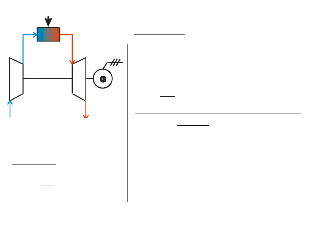
stationary gas power-
station
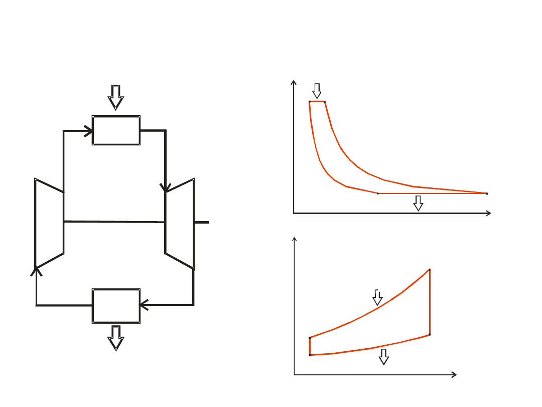
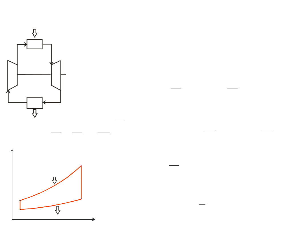
Joule cycle
Brayton-Armengaud cycle
1
2
4
3
q
o
q
d
P
m
1
2
3
4
Q
d
q
o
T
s
1
2
3
4
Q
d
q
o
P
V
closed system
q
d
q
d
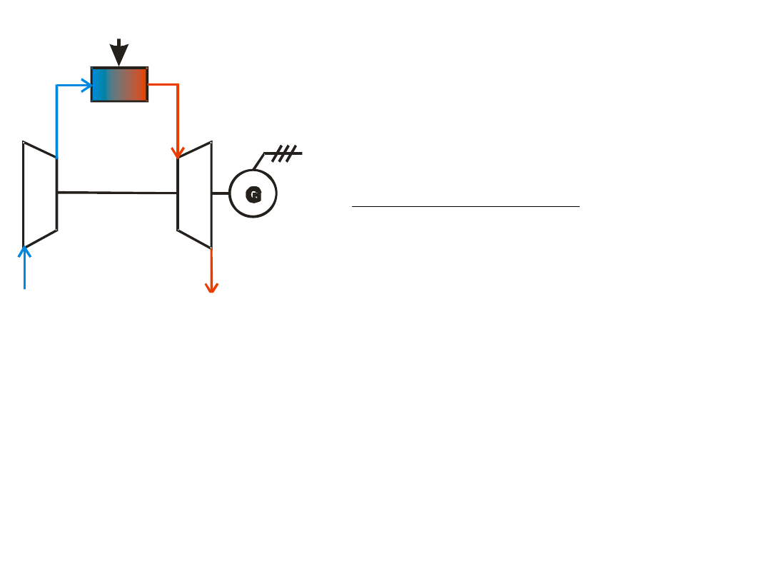
Theroretical – model
case
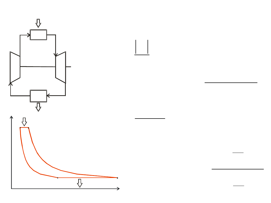
efficiency of the
cycle
1
2
4
3
q
o
q
d
P
m
d
o
t
q
q
1
2
3
1
4
1
T
T
c
T
T
c
p
p
t
2
3
1
4
1
T
T
T
T
t
1
1
1
2
3
2
1
4
1
T
T
T
T
T
T
t
1
2
3
4
Q
d
q
o
P
V
q
d
Theroretical – model
case
efficiency of the cycle
1
2
4
3
q
o
q
d
P
m
k
k
k
k
p
p
T
T
i
p
p
T
T
1
4
3
4
3
1
1
2
1
2
4
3
1
2
2
3
4
1
p
p
p
p
p
p
i
p
p
2
3
1
4
4
3
1
2
T
T
T
T
T
T
T
T
k
k
t
p
p
T
T
T
T
1
1
2
1
2
2
1
1
1
1
1
1
k
k
t
1
1
1
t
k
k
1
1
1
2
3
4
Q
d
q
o
T
s
q
d
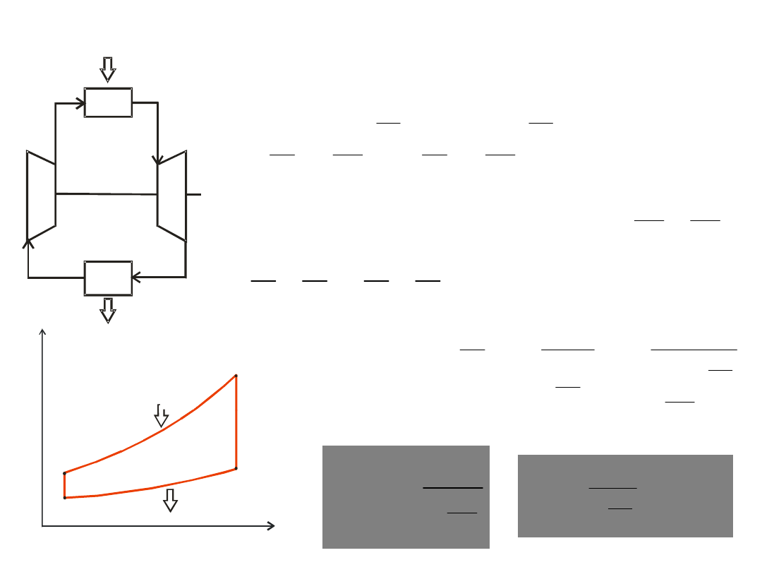
Theroretical – model
case
work
1
2
4
3
q
o
q
d
P
m
C
T
t
l
l
l
4
3
i
i
l
T
T
1
– minimal temperature of the cycle;
(resulted from external conditions)
T
3
=T
max
results from internal limitations (material features)
1
2
3
4
Q
d
q
o
T
s
- work at the cycle
- work of the turbine
as for an ideal gas
p
p
T
c
T
c
T
l
4
3
1
2
i
i
l
S
- work of the compressor
as for an ideal gas
p
p
C
c
T
c
T
l
1
2
summary
)
(
)
(
1
2
4
3
p
p
p
p
t
c
T
c
T
c
T
c
T
l
q
d
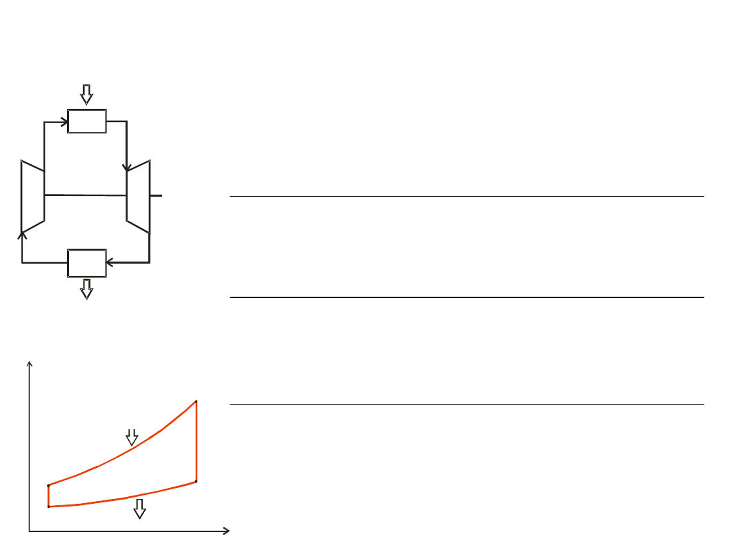
Theroretical – model
case
work
1
2
4
3
q
o
q
d
P
m
k
k
p
p
T
T
T
T
1
1
2
4
3
1
2
1
1
1
2
1
3
4
3
T
T
T
c
T
T
T
c
l
p
p
t
1
1
1
2
1
2
1
3
T
T
T
c
T
T
T
c
l
p
p
t
:
1
2
then
T
T
if
1
1
1
1
3
T
c
T
c
l
p
p
t
1
2
3
4
Q
d
q
o
T
s
)
(
)
(
1
2
4
3
p
p
p
p
t
c
T
c
T
c
T
c
T
l
q
d
Theroretical – model
case

maximal work for T
max
and T
min
const. :
0
d
dl
t
0
1
1
2
max
T
c
T
c
d
dl
p
p
t
k
k
opt
opt
k
k
opt
opt
T
T
p
p
p
p
T
T
2
1
min
max
1
2
1
1
2
1
max
1
2
T
T
as
then
min
max
2
T
T
T
opt
Theroretical – model
case
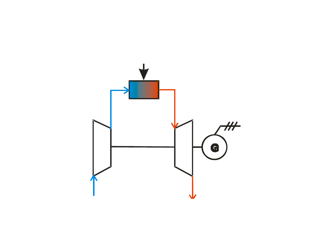
Open cycle – gas power unit
Powietrze
Spaliny
Paliwo
1
2
4
3
P
e
open cycle
fuel
air
exhaust gases
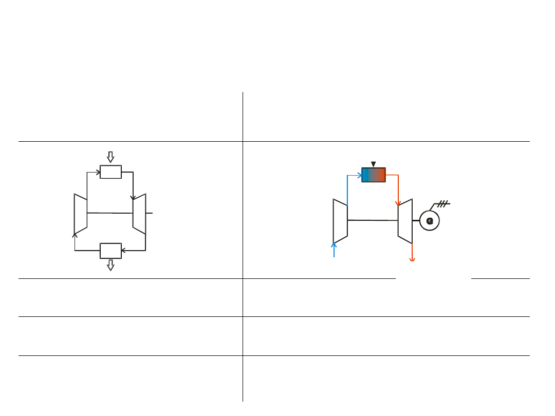
closed and open cycles
Powietrze
Spaliny
Paliwo
1
2
4
3
P
e
1
2
4
3
q
o
q
d
P
m
closed
open
m
1
=m
2
=m
3
=m
4
m
1
=m
2
≠m
3
=m
4
one agent
air/exhaust gases
possible choice of an agent
with a better k and c
p
/ρ
fuel
air
exhaust
gases
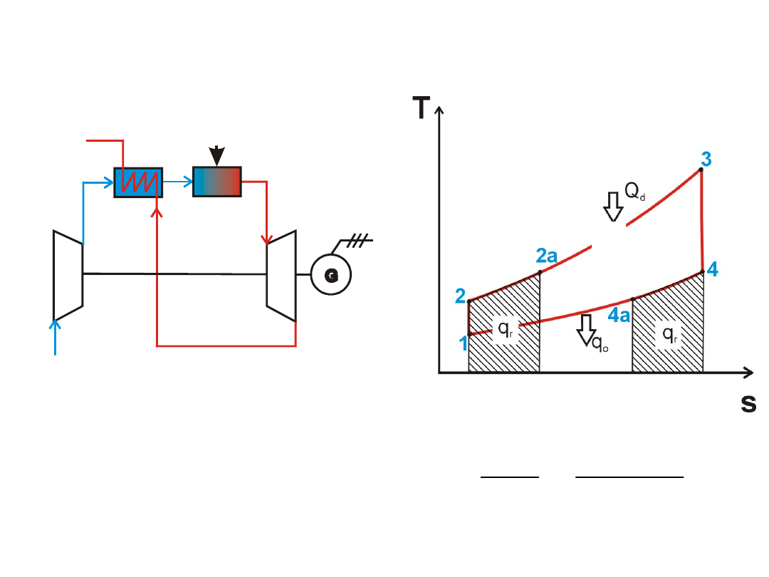
a cycle with a regeneration
system
P o w ie tr z e
S p a lin y
P a liw o
1
2 a
4 a
3
P
e
2
4
fuel
air
exhaust gases
q
d
2
4
2
2
T
T
T
T
Q
Q
a
r
r
Regeneration
factor:
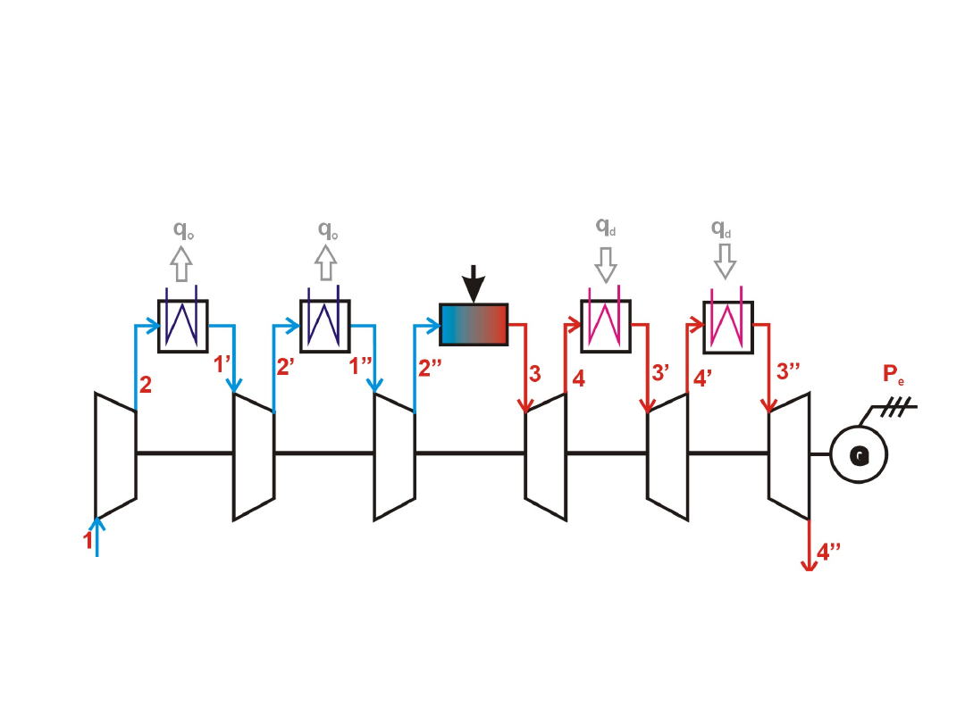
a cycle with intersectional cooling and
heating
exhaust gases
air
fuel
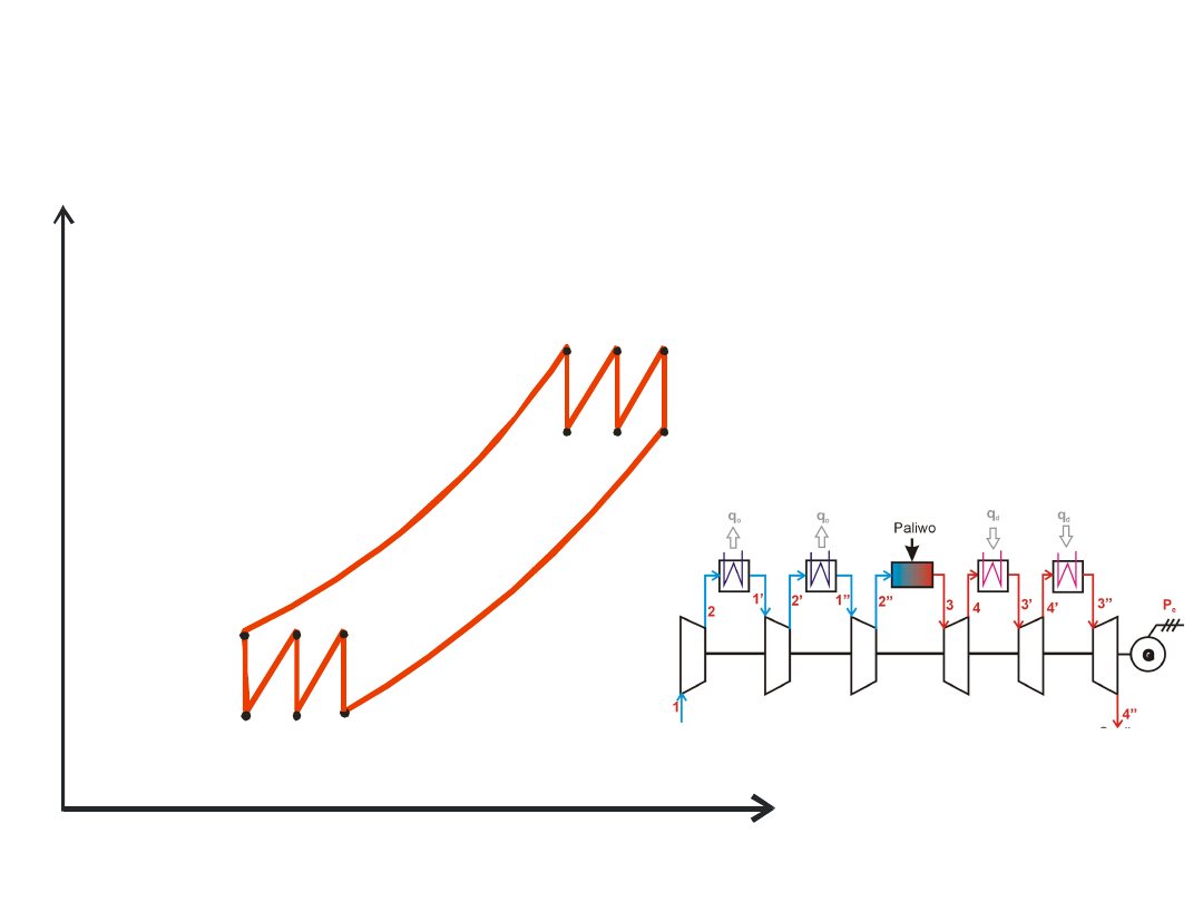
a cycle with intersectional cooling and
heating
1’
2
3’
4’
T
s
1”
1
2’
2”
3”
3
4”
4
air
exhaust
gases
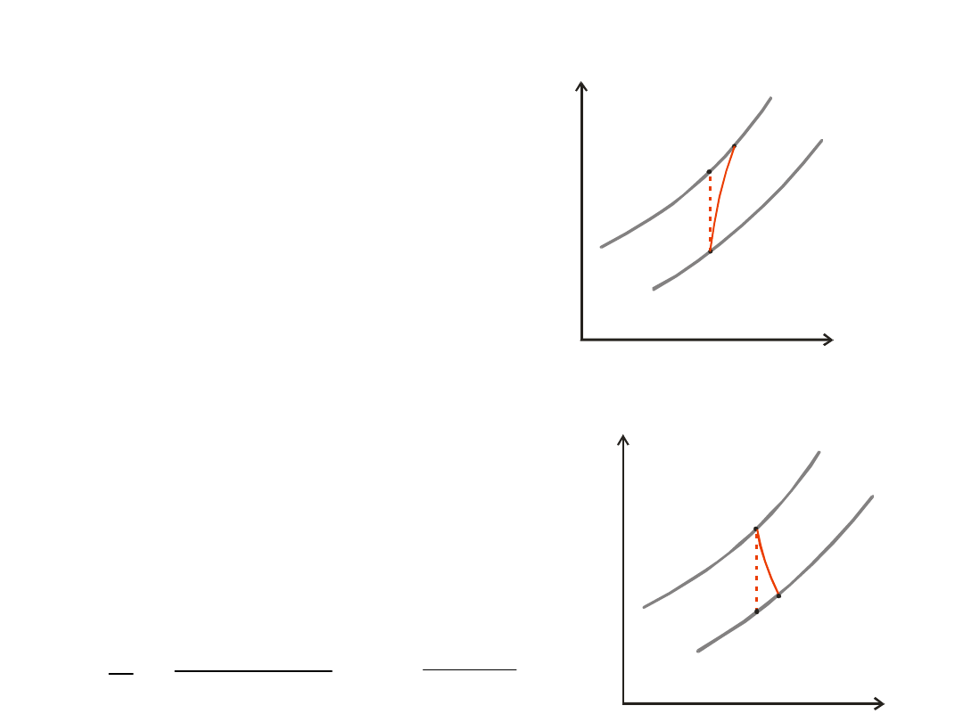
real cycles
• c
p
– changes with T
(c
p
=f(T))
• different mass flows
and different agents
• losses at the
compressor
• losses at the turbine
• losses at the
combustion
chamber
2r
T
s
1
2t
p1
p2
2r
T
s
1
2t
p1
p2
t
r
iT
l
l
t
p
r
p
T
T
c
T
T
c
2
1
2
1
t
r
T
T
T
T
2
1
2
1
compressor
turbine
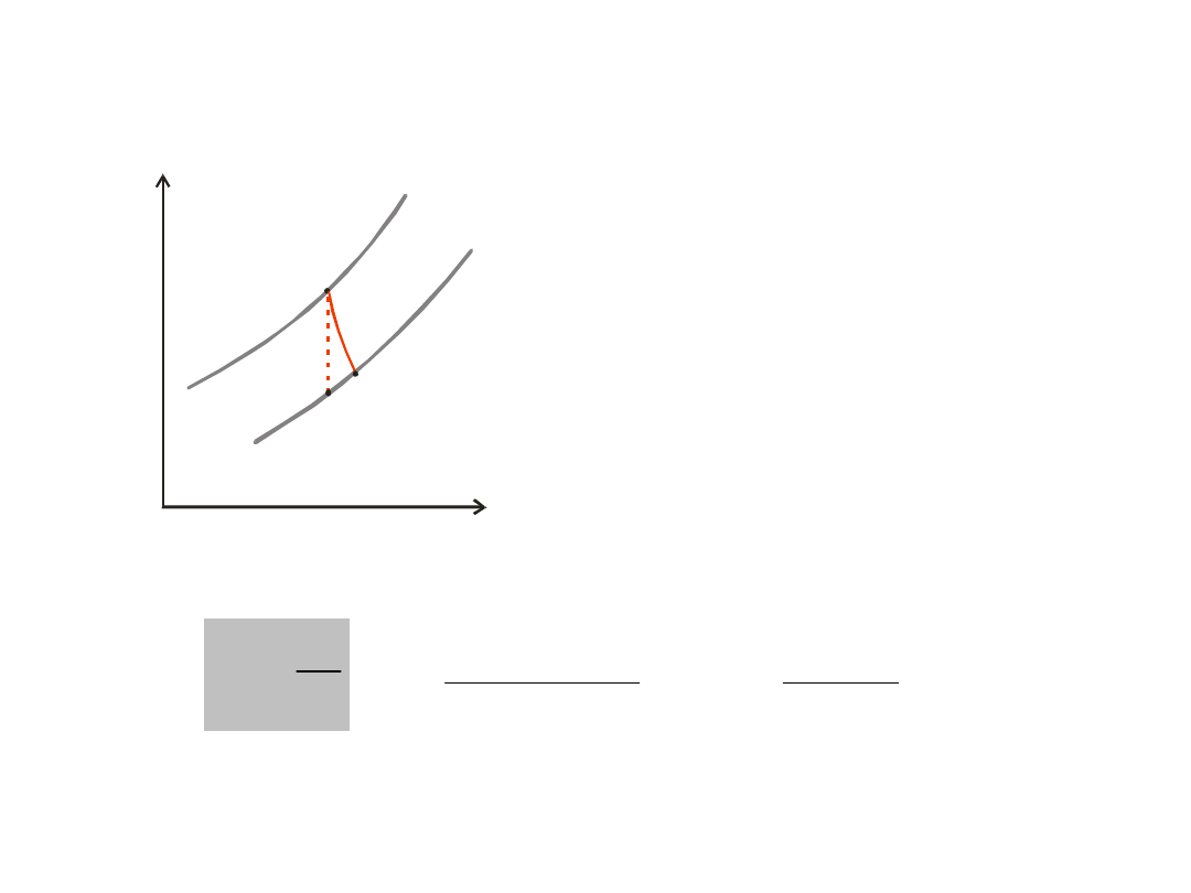
turbine – internal efficiency
2r
T
s
1
2t
p1
p2
tT
rT
iT
l
l
t
p
r
p
T
T
c
T
T
c
2
1
2
1
t
r
T
T
T
T
2
1
2
1
turbine
balances
Powietrze
Spaliny
Paliwo
1
2
4
3
P
e
compressor
1
2
_
T
T
c
l
air
p
iC
1
2
T
T
c
m
m
l
P
pp
p
p
is
iC
turbine
4
3
_
T
T
c
l
eg
p
iT
4
3
T
T
c
m
m
l
P
ps
s
s
iT
iT
ms
is
mC
P
P
mT
iT
mT
P
P
power balance at the shaft:
G
el
mG
P
P
generator
mG
mC
mT
P
P
P
fuel
air
exhaust gases
CC
C
T
balances
Powietrze
Spaliny
Paliwo
1
2
4
3
P
e
combustion chamber
gases
exhaust
fuel
air
m
m
m
_
3
_
_
_
2
_
T
c
m
m
HCV
T
c
m
g
ex
p
gases
exhaust
CC
fuel
air
p
air
mass balance
energy balance
fuel
air
exhaust gases
C
T
CC

mechanical output
mC
iC
mT
iT
mC
iC
mT
iT
eC
eT
e
P
P
P
P
P
P
P
P
P
)
(
)
(
mC
iC
tC
air
mT
iT
tT
eg
mC
iC
air
mT
iT
eg
e
l
m
l
m
l
m
l
m
P
mC
iC
t
air
p
air
mT
iT
t
eg
p
fuel
air
e
T
T
c
m
T
T
c
m
m
P
)
(
)
(
)
(
1
2
_
4
3
_

mechanical
output
mC
iC
t
air
p
air
mT
iT
t
eg
p
fuel
air
e
T
T
c
m
T
T
c
m
m
P
)
(
)
(
)
(
1
2
_
4
3
_
mC
iC
k
k
air
p
air
mT
iT
k
k
eg
p
fuel
air
e
air
air
eg
eg
p
p
T
c
m
p
p
T
c
m
m
P
1
1
)
(
1
1
2
min
_
1
3
4
max
_
eg
air
eg
p
air
p
eg
air
k
k
c
c
m
m
g
simplifyin
;
;
:
_
_
1
1
1
min
max
mC
iC
mT
iT
p
e
T
T
c
m
P
k
k
p
p
noting
p
p
p
p
and
1
1
2
4
3
1
2
:
;
:

mechanical
output
1
1
1
min
max
mC
iC
mT
iT
p
e
T
T
c
m
P
mC
iC
mT
iT
p
e
T
T
c
m
P
min
2
max
1
mC
iC
mT
iT
e
T
T
if
P
min
max
:
0
k
k
mC
iC
mT
iT
opt
opt
T
T
p
p
so
2
1
min
max
1
2
:

internal work
heat delivered
th
=
r
p
r
p
r
p
d
i
th
T
T
c
T
T
c
T
T
c
Q
P
2
3
1
2
4
3
power output
heat delivered (in time)
o
=
thermal efficiency
overall efficiency
HCV
m
P
Q
P
P
fuel
e
d
mC
mT
o

overall efficiency
CC
r
air
p
air
eg
p
eg
mC
iC
t
air
p
air
mT
iT
t
eg
p
fuel
air
fuel
e
o
T
c
m
T
c
m
T
T
c
m
T
T
c
m
m
HCV
m
P
2
_
3
_
1
2
_
4
3
_
)
(
)
(
)
(
CC
iC
k
k
air
p
air
eg
p
fuel
air
mC
iC
k
k
air
p
air
mT
iT
k
k
eg
p
fuel
air
o
air
air
air
air
eg
eg
T
c
m
T
c
m
m
T
c
m
T
c
m
m
)
1
(
1
)
(
)
1
(
)
1
1
(
)
(
1
min
_
max
_
1
min
_
1
max
_
iC
k
k
iC
t
r
air
p
air
air
p
p
T
T
T
T
T
const
c
if
1
1
.
1
1
2
1
1
2
1
2
_

overall efficiency
iC
CC
mC
iC
mT
iT
o
T
T
T
T
)
1
(
1
)
1
(
)
1
1
(
min
max
min
max
eg
air
eg
p
air
p
eg
air
k
k
c
c
m
m
g
simplifyin
;
;
:
_
_
k
k
p
p
noting
1
1
2
:
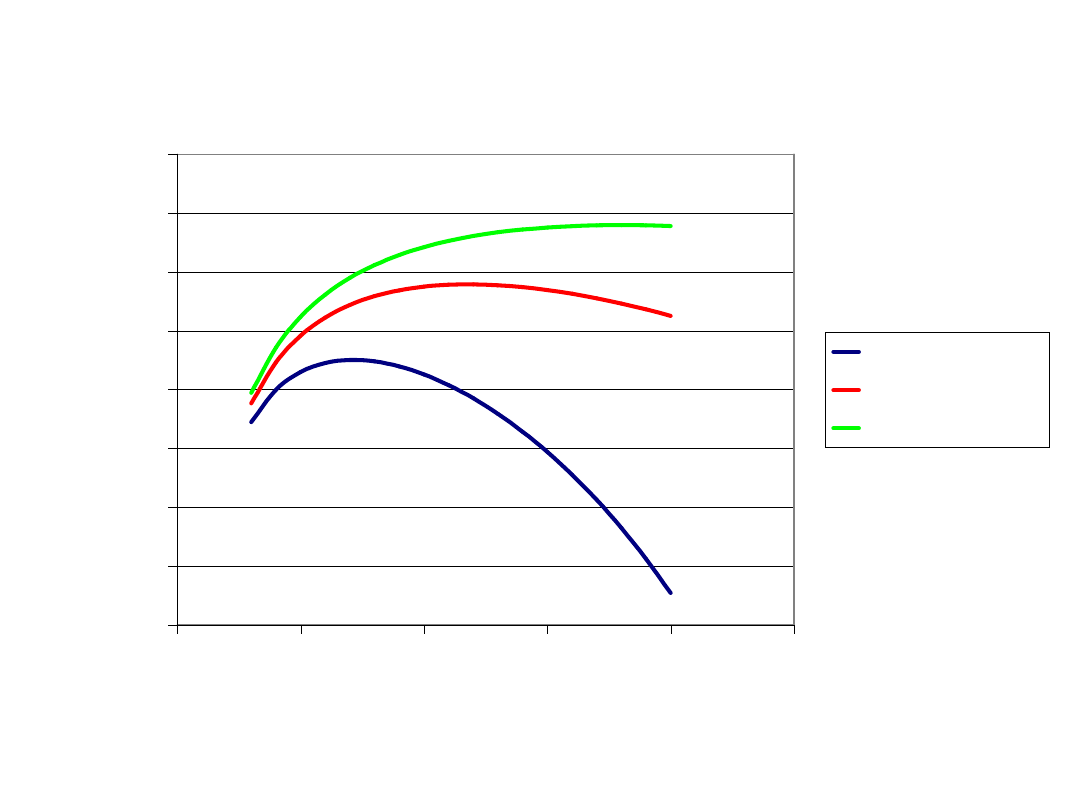
overall efficiency changes
0
0,05
0,1
0,15
0,2
0,25
0,3
0,35
0,4
0
5
10
15
20
25
spręż pi
sp
ra
w
n
o
ść
t
u
rb
o
ze
sp
o
łu
Tmax=900 k
Tmax=1100 k
Tmax=1300 k
compression
o
v
e
ra
ll
e
ffi
ci
e
n
cy
for assumed
values of inner
and
mechanical
efficiencies
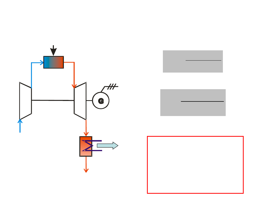
Recovery of exhaust gases enthalpy
– combined heat and power generation with a
gas cycle
Powietrze
Spaliny
Paliwo
1
2
5
3
P
e
4
Q
u
HCV
m
Q
P
fuel
u
el
CHP
HCV
m
P
fuel
el
el
air
exhaust
gas
fuel
T
C
CC
Remark:
It is also in practice to
relate overall efficiencies
of power units or CHP
plants based on gas
cycles to LCV

Exercise 1
A simple stationary gas system consists with an one-section roto-dynamic compressor,
a combustion chamber, a gas turbine, and an electricity generator. The compressor
sucks 150 kg/s of an ambient air (t
a
=10°C, p
a
=997 hPa) and compresses it to p
2
=1.3
MPa. The internal polytrophic efficiency of the compressor is η
ipC
=0.88. Mechanical
losses at the compressor are estimated on about 35 kW. The compressed air flows into
the combustion chamber. The combustion chamber is supplied with natural gas of
LCV=37.26 MJ/m3, HCV=41.26 MJ/m3, and density ρ=0.784 kg/m3 (all those
parameters are given for standard conditions: 0.1013 MPa, 0°C). The actual pressure of
the gas is 1.3 MPa and temperature 20°C. It can be assumed that an overall efficiency
of the combustion chamber is η
CC
=0.98. One can assume also that the combustion
process is isobaric. Exhaust gases generated at the combustion chamber have a
temperature t
3
=1300 °C and supply the gas turbine where expand up to p
4
=1.02 bar.
The exhaust gases leave the gas turbine with a temperature t4=570°C. The gas turbine
drives the compressor and the generator. A mechanical efficiency of the turbine is
η
mT
=0.993 and an overall efficiency of the generator is η
G
=0.98.
Accept: c
pair
=1.004 kJ/kgK, c
pex.g.
=1.04 kJ/kgK, k
air
=1.4, k
ex.g
=1.39
Calculate:
1.
internal adiabatic efficiency of the compressor,
2.
mechanical power driving the compressor and mechanical efficiency of the compressor,
3.
fuel consumption at the combustion chamber
4.
electricity output form the generator
5.
overall efficiency of the power plant

Exercise 2
A gas cycle power plant consists with an one-section roto-dynamic
compressor, a combustion chamber, a gas turbine, an electricity
generator, and a recuperator. The compressor sucks an ambient air
(t
a
=0°C, p
a
=1 bar hPa) and compresses it to p
2
=0.7 MPa. The internal
adiabatic efficiency of the compressor is η
ipC
=0.85 and a mechanical
efficiency is η
mC
=0.994. The compressed air flows into the iso-baric
recuperator, and is heated by a exhaust gases flowing form the turbine,
up to 530°C. The superheated and compressed air supplies the
combustion chamber where a fuel oil (HCV-46 MJ/kg) is combusted (also
an iso-baric process). An overall efficiency of the combustion chamber is
η
CC
=0.98. Exhaust gases temperature behind the combustion chamber is
t
3
=1100 °C. The exhaust gases expand at the turbine up to p
4
=1 bar with
an internal efficiency of the process η
iT
=0,89. The gas turbine drives the
compressor and the generator. A mechanical efficiency of the turbine is
η
mT
=0.992 and an overall efficiency of the generator is η
G
=0.975.
Electricity output of the power unit is 40 MWe.
Accept: c
pair
=1.004 kJ/kgK, c
pex.g.
=1.04 kJ/kgK, k
air
=1.4, k
ex.g
=1.39
Calculate:
1.
fuel consumption at the combustion chamber
2.
overall efficiency of the power plant
3.
regeneration factor
4.
outlet temperature of the exhaust gases
Document Outline
- Slide 1
- Slide 2
- Slide 3
- Slide 4
- Slide 5
- Slide 6
- Slide 7
- Slide 8
- Slide 9
- Slide 10
- Slide 11
- Slide 12
- Slide 13
- Slide 14
- Slide 15
- Slide 16
- Slide 17
- Slide 18
- Slide 19
- Slide 20
- Slide 21
- Slide 22
- Slide 23
- Slide 24
- Slide 25
- Slide 26
Wyszukiwarka
Podobne podstrony:
Moss inert gas system
Gas systems after market services
ENG LINUX System Administrators Nieznany
07 04 Saloon with bulb failure warning system (with gas discharge headlamps)
SKELETAL SYSTEM dla stud Eng
Lambda Control System AL 720 ENG
6548 Octan Gas Station (1 z 5)
Hydrogen Gas Injector System For Internal Combustion Engine
6548 Octan Gas Station (2 z 5)
SMeyer CA1227094A1 Hydrogen Air & Non Combustible Gas Mixing Combustion System
6548 Octan Gas Station (4 z 5)
#0202 – At the Gas Station
6548 Octan Gas Station (3 z 5)
6548 Octan Gas Station (5 z 5)
System for Shooting Using Compressed Gas US Patent 5909000
Lambda Control System AL 720 ENG
więcej podobnych podstron