
Part Creation in GibbsCam
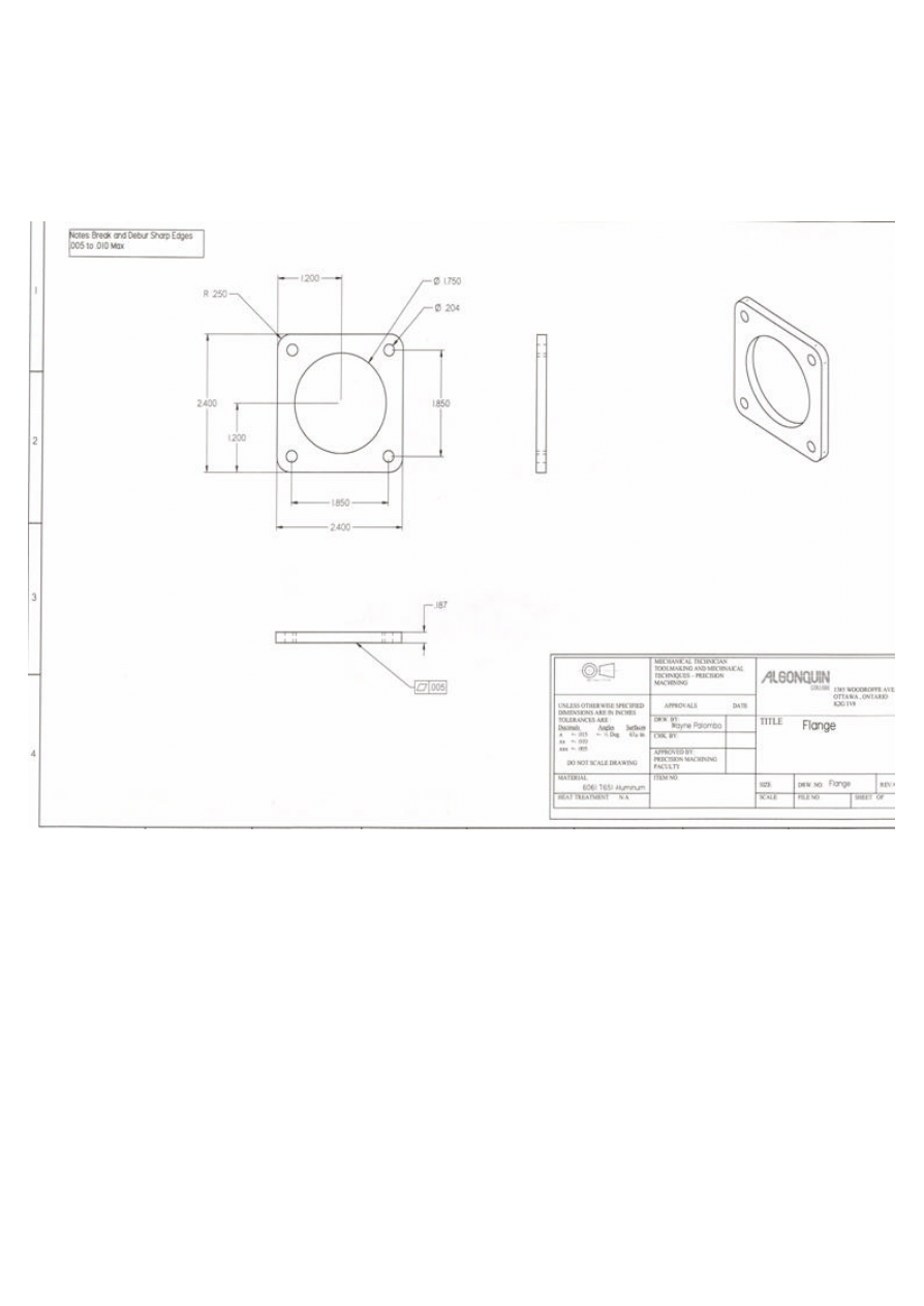
Ex Part: Flange
Defining Stock
1. Open up the “Document” control Box
2. Set X+ @ 2.6, X- @ 0, Y+ @ 0, Y- @ -2.6, Z+ @ 0, Z- @ -.500
3. Set the Clearance plane at .500
4. Turn on your “View Control” Box
5. Set Part to “top” View
Defining Origin
6. Modify
7. Move Part Origin
8. Move the origin until there is no additional stock in the X-, Y+, & Z+ areas
9. Clue : Keep your “stock” size or Document control Box open.
Look at the values and move the part origin by the amount of overlap.
Creating Geometry
10. Open up Geometry Palette
11. Click the “Shape” Dialogue
12. Click on the “Box” feature
13. We want to create a box 2.4 X 2.4 so enter these values as the X & Y values
14. Center Posit ion ( This is CRITICAL ) as this is the relationship between
a) The raw stock that you have defined, b) Your part origin, c) Your geometry
15.
For center position enter X 1.3, Y -1.3, Z 0
You now have a 2.4 Square box contained within a 2.6 Square stock size.

15. Unsing the View control box toggle your geometry through the different views to
ensure that X,Y,Z, origins as well as Stock and Geometry looks correct.
16. Creating Circles
17. Click the “Return Key” on the Geometry Palette, to return your icon to the Home
position. This will bring up the Point, Line, Circle Dialogue Box
18. Click the “circle feature”
19. “Radius and Center Point”
20. Click on the C.P Button
21. X 1.3, Y -1.3, Z 0 R.875
22. Click the “two circles” to leave this dialogue box open. This should have created
your 1.750 ø Circle in the center of your part.
23. Using Math, determine the correct X & Y locations for the 4 .204ø holes and
repeat this process using the supplied “Flange” Blueprint
24. Return to the “Home View” again for your Geometry creation
25. Next step, adding Fillets, or Radii to existing geometry.
26. Using the Auto Fillet/Chamfer Button first Highlight your box by double clicking.
27. Auto Fillet button
28. Radius with C.P
29. Enter in a Radius value as per the supplied drawing R.250
30. Click the circle icon.
Your screen/geometry should now look exactly like the supplied drawing !!
Wayne Palombo 2005-09-14
Wyszukiwarka
Podobne podstrony:
Dan Harlan Creativity In 9 Steps
part 2 9 Context in Dynamic Interpretation
Exercises in morphology, part 3
conceptual storage in bilinguals and its?fects on creativi
Creating Space in the Midfield
Poland to Take Part in Administration of Iraq
In Nomine The Rats' Revenge Part I
Building Applications and Creating DLLs in LabVIEW
Nugent 5ed 2002 The Government and Politics in the EU part 1
Creating a COM object in ASM
Should Creationism? Taught in Public Schools
Exercises in morphology, part 3
Loving in Truth Creating a Society of Living in Harmony
SN 19 Marcin Łączek Creative methods in teaching English
79 Creating Space and Support from Behind in a 1v1 ( 1) pra
A campaign of the great hetman Jan Zamoyski in Moldavia (1595) Part I Politico diplomatic and milita
I´m BACH in the USSR (southern part) Alto Saxophone, Flute
(ebook ITA FOTOGRAFIA) Creatività e tecnica in bianconero (PDF)
Loudspeakers in Vented Boxes Part I
więcej podobnych podstron