
Polypropylene
Injection Molding Problems & Solutions
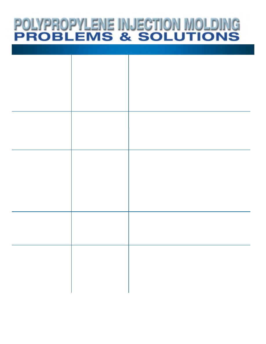
Problem
1.
Sink Marks
2.
Voids
3.
Shrinkage
4.
Poor Weld Line Strength
5.
Flash
Causes
Part is underfilled or has
excessive shrinkage in
thicker sections
Part is underfilled or has
excessive shrinkage
Volume decreases as
plastic cools and crystal-
lizes or part is not fully
packed out due to gates
freezing off too soon or
insufficient cooling time
The convergence of flow
fronts past an obstacle
or merging flow fronts in
multi-gated molds results
in a weak, interfacial bond
Insufficient clamp force,
mold surface is deflecting,
mold shutoff surfaces not
seating properly
Possible Solutions
•
Increase shot size
•
Maintain adequate cushion
•
Increase cavity or hold pressure
•
Melt or mold temperature too high (if gate freeze-off too slow)
•
Increase hold time
•
Reduce fill rate
•
Cool sink area faster
•
Open gates
•
Reduce wall thickness of intersecting rib or boss
•
Improper gate locations or design
•
Incomplete mold fill (short shot)
•
Maintain adequate cushion
•
Poor venting
•
Improper gate location
•
Injection rate too high
•
Excessive part thickness (+ 0.25 in. or 0.64 cm.)
•
Excessive shrinkage – Increase cavity pressure and hold time
•
Part oversized or not enough shrinkage – Decrease cavity
pressure
•
Maintain adequate cushion
•
Increase hold time
•
Delay gate sealing to allow pack out (increase melt
temperature)
•
Mold or melt temperature too high (gates not freezing off)
•
Improperly balanced cavity and core temperatures
•
Runners or gates too small
•
Wall thickness variation
•
Increase peak cavity pressure (fill faster)
•
Increase mold and melt temperatures
•
Increase hold pressure and time
•
Change gate location
•
Decrease peak cavity pressure (decrease fill rate and/or
use profile injection)
•
Decrease melt temperature
•
Increase clamp force
•
Clean mold surfaces
•
Check mold surface for flatness
•
Check integrity of mold shutoff
•
Change gate location
•
Use larger press
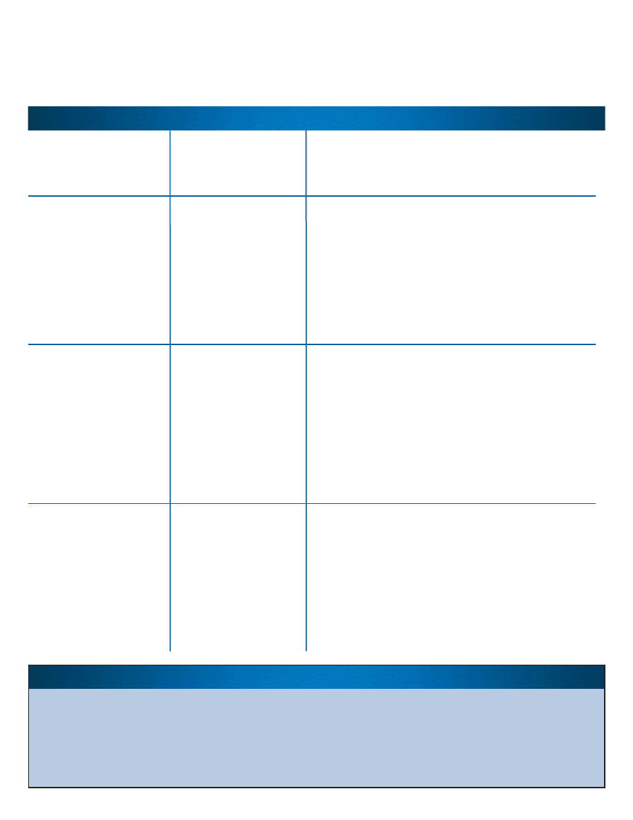
Problem
6.
Burning
7.
Warp
8.
Brittle Parts
9.
Poor Appearance
(Flow marks, low
gloss, rough surface,
jetting, orange peel,
etc.)
Causes
Compressed air in the
mold degrades resin
Non-uniform stress due
to excessive orientation
and/or shrinkage
Excessive orientation,
degradation of resin, over
packing, contamination, or
improper design
Flow front slips-sticks on
mold surface, jets, or
pulsates
Possible Solutions
•
Decrease peak cavity pressure (decrease fill rate and/or
use profile injection)
•
Clean vents, increase size or number of vents
•
Reduce melt temperature
•
Part ejected too hot (increase cycle time)
•
Mold at high temperatures, low pressures, and moderate
fill rates
•
Decrease injection fill rate
•
Improperly balanced core and cavity temperature
•
Molded in stress due to low stock temperature and
cold mold
•
Minimize hot spots in mold
•
Improperly balanced multiple gates
•
Flow too long, insufficient gates
•
Change gate location
•
Increase injection fill rate
•
Increase melt temperature
•
Increase mold temperature and cool time
•
Over packing (decrease hold pressure and time)
•
Degraded material (excessive melt temperature or
long residence time in barrel)
•
Contamination from other polymers
•
Use of incompatible carrier resins in color concentrates or
other additives
•
Unintentional nucleation from pigments
•
Improper design; inadequate radii at corners, notches,
or threads
•
Increase cavity pressure
•
Fill speed and/or packing time too low
•
Increase melt and/or mold temperature
•
Cool more slowly
•
Mold temperature non-uniform or too low
•
Insufficient lubrication (internal lubricant or on tool surface)
•
Excessive mold lubricant (e.g. grease bleeding out of
the mold)
•
Dirty mold surface (clean and/or polish)
•
Poor pigment dispersion
•
Increase venting
•
Improper gate location or design
General Processing Guidelines
Cushion:
0.25 in., 0.64 cm.
Times (sec):
Boost –
2-10
Hold –
Adjust for gate
freeze-off
Cooling – Depends on
part thickness
Pressures:
Boost – 500-1500 psi,
3.45-10.34 MPa
Hold – 50-75% of Boost
Back – 50-100 psi,
.34-.69 MPa
Screw RPM – medium
to fast
Mold Temperature:
60-120°F, 15-49°C
Barrel Temperature:
Rear – 390-440°F,
199-227°C
Middle – 390-450°F,
199-232°C
Front – 390-460°F,
199-238°C
Melt Temperature:
400-460°F,
204-238°C
Drying:
Generally unnecessary;
however, may be required
for aesthetic purposes or
with highly filled products
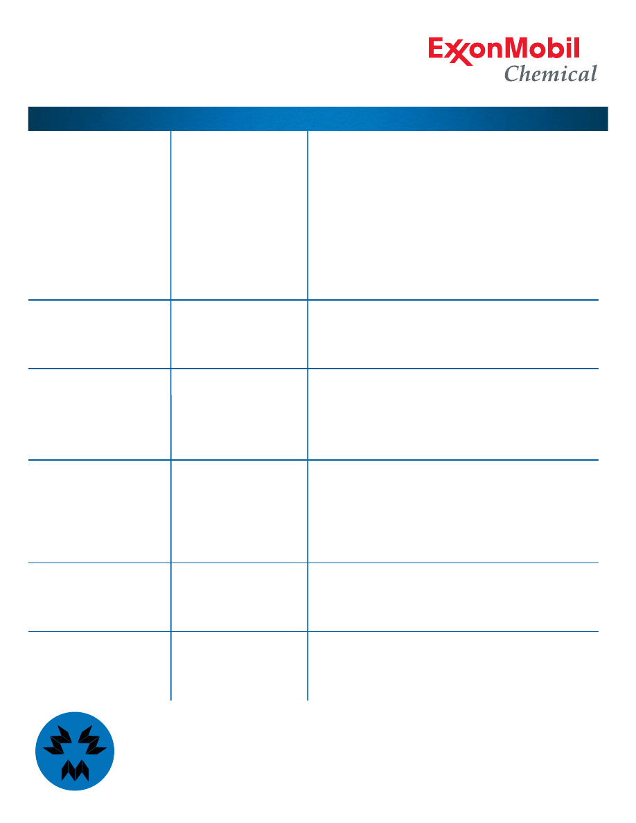
Problem
10.
Sticking in Mold
11.
Gate Blush,
Delamination or
Cracking at the Gate
12.
Black Specks or
Discoloration
13.
Short Shot
14.
Splay
15.
Gate Stringing
Causes
Over packing, excessive
shrinkage, tool design
causes physical attach-
ment to the core or cavity
Melt fracture
Degradation
Underfilled part
Streaks on surface
caused by volatiles such
as moisture or degraded
material
Plastic strings on parts
located at the gates
formed during ejection
Possible Solutions
•
Over packing, injection pressure too high – reduce
•
Under packing, excessive shrinkage – see solutions to
Short Shot
•
Improperly balanced mold temperatures (colder on
movable half)
•
Reduce cycle time (sticking on cores)
•
Increase cycle time (sticking in cavities)
•
Insufficient knockouts
•
Remove undercuts
•
Increase draft angles
•
Surface irregularities in the mold (polish cavity surfaces)
•
Highly polished core surface (vacuum lock), polish to a
coarser finish, apply a surface coating, or increase venting
•
Adjust injection speed (increase or decrease)
•
Modify gate geometry (e.g. gate too small, land too long)
•
Add cold slug wells in runners
•
Increase melt and/or mold temperature
•
Excessive melt temperature or residence time in barrel
•
Improper venting
•
Possible contamination
•
Excessive screw RPM
•
Excessive back-pressure
•
Excessive shear created by the use of a mixing screw
•
Increase shot size
•
Inadequate cushion
•
Increase fill speed, pack pressure, and/or injection time
•
Increase melt and/or mold temperature
•
Plugged gates, runners, or vents
•
Inadequate melt flow rate (use higher MFR material)
•
Undersized gates, runners, and vents
•
Volatiles created by hot spot in manifold
•
Excessive moisture (dry resin)
•
Reduce melt temperature
•
Increase gate size (reduce orientation)
•
Decrease melt temperature, increase cooling time
•
Decrease drop tip temperature
•
Increase mold opening speed (break strings upon ejection)
•
Use valve gates
MYTEX
POLYMERS


©2003 Exxon Mobil Corporation. To the extent
the user is entitled to disclose and distribute this
document, the user may forward, distribute,
and/or photocopy this copyrighted document
only if unaltered and complete, including all of its
headers, footers, disclaimers, and other informa-
tion. You may not copy this document to a Web
site. ExxonMobil does not guarantee the typical
(or other) values. Analysis may be performed on
representative samples and not the actual prod-
uct shipped. The information in this document
relates only to the named product or materials
when not in combination with any other product
or materials. We based the information on data
believed to be reliable on the date compiled, but
we do not represent, warrant, or otherwise guar-
antee, expressly or impliedly, the merchantability,
fitness for a particular purpose, suitability, accura-
cy, reliability, or completeness of this information
or the products, materials, or processes
described. The user is solely responsible for all
determinations regarding any use of material or
product and any process in its territories of inter-
est. We expressly disclaim liability for any loss,
damage, or injury directly or indirectly suffered or
incurred as a result of or related to anyone using
or relying on any of the information in this docu-
ment. There is no endorsement of any product or
process, and we expressly disclaim any contrary
implication. The terms, “we,” “our,” “ExxonMobil
Chemical,” or “ExxonMobil” are used for conven-
ience, and may include any one or more of
ExxonMobil Chemical Company, Exxon Mobil
Corporation, or any affiliates they directly or indi-
rectly steward. ExxonMobil and the “Interlocking
X” Device are trademarks of Exxon Mobil
Corporation. Mytex, Mytex Polymers and the
Mytex Logo are trademarks of Mytex Polymers
Incorporated.
Printed in U.S.A. • May 2003 • PPIM03 • 2,000
Offices
Worldwide Headquarters,
North America
ExxonMobil Chemical Company
13501 Katy Freeway
Houston, Texas 77079-1398, USA
Tel. (281) 870-6000/(800) 231-6633
Fax (281) 870-6661
Europe
ExxonMobil Chemical
Hermeslaan 2
1831 Machelen, Belgium
Tel. 32 2 722 21 11
Fax 32 2 722 27 80
Asia Pacific
ExxonMobil Chemical
1 HarbourFront Place
#06-00 HarbourFront Tower One
Singapore 098633
Tel. 65-6885-8312
Fax 65-6885-8405
Middle East and Africa
ExxonMobil Chemical
Hermeslaan 2
1831 Machelen, Belgium
Tel. 32 2 722 21 11
Fax 32 2 722 27 80
Latin America
ExxonMobil Chemical
13501 Katy Freeway
Houston, Texas 77079-1398
Tel. (281) 870-6000/(800) 231-6633
Fax (281) 870-6661
For a complete listing of sales offices, please visit
Sales & Support at www.exxonmobilpp.com.
www.exxonmobilpp.com
www.exxonmobilchemical.com
Wyszukiwarka
Podobne podstrony:
SHSBC379 PROBLEMS AND SOLUTIONS
44th International Mathematical Olympiad Short listed problems and solutions(2003)
4 PIM Powder Injection Molding
Bulk and Solution Polymerizations Reactors
Injection Molding
Optimization of injection molding process parameters using sequential simplex algorithm
Societys Problems and my role in helping it
A Plastic Injection Molding Process Characterisation Using Experimental Technique (Jtdis41a01)
MERTON Social Problems and Sociological Theory
Health problems and illnesses
Critical Management Studies Premises, Practices, Problems, and Prospects
Decoherence, the Measurement Problem, and Interpretations of Quantum Mechanics 0312059
Injection Molding Mold Design
101 Project Management Problems and How to Solve Them 2011
więcej podobnych podstron