
U.S. ARMY MEDICAL DEPARTMENT CENTER AND SCHOOL
FORT SAM HOUSTON, TEXAS 78234-6100
REFRIGERATOR
AND FIELD SINK
SUBCOURSE MD0367 EDITION 100

DEVELOPMENT
This subcourse is approved for resident and correspondence course instruction. It
reflects the current thought of the Academy of Health Sciences and conforms to printed
Department of the Army doctrine as closely as currently possible. Development and
progress render such doctrine continuously subject to change.
ADMINISTRATION
Students who desire credit hours for this correspondence subcourse must enroll in the
subcourse. Application for enrollment should be made at the Internet website:
http://www.atrrs.army.mil. You can access the course catalog in the upper right corner.
Enter School Code 555 for medical correspondence courses. Copy down the course
number and title. To apply for enrollment, return to the main ATRRS screen and scroll
down the right side for ATRRS Channels. Click on SELF DEVELOPMENT to open the
application; then follow the on-screen instructions.
For comments or questions regarding enrollment, student records, or examination
shipments, contact the Nonresident Instruction Branch at DSN 471-5877, commercial
(210) 221-5877, toll-free 1-800-344-2380; fax: 210-221-4012 or DSN 471-4012, e-mail
accp@amedd.army.mil, or write to:
NONRESIDENT INSTRUCTION BRANCH
AMEDDC&S
ATTN:
MCCS-HSN
2105 11TH STREET SUITE 4191
FORT SAM HOUSTON TX 78234-5064
Be sure your social security number is on all correspondence sent to the Academy of
Health Sciences.
CLARIFICATION OF TERMINOLOGY
When used in this publication, words such as "he," "him," "his," and "men" 'are intended
to include both the masculine and feminine genders, unless specifically stated otherwise
or when obvious in context.
USE OF PROPRIETARY NAMES
The initial letters of the names of some products may be capitalized in this subcourse.
Such names are proprietary names, that is, brand names or trademarks. Proprietary
names have been used in this subcourse only to make it a more effective learning aid.
The use of any name, proprietary or otherwise, should not be interpreted as
endorsement, deprecation, or criticism of a product; nor should such use be considered
to interpret the validity of proprietary rights in a name, whether it is registered or not.

MD0367 i
TABLE OF CONTENTS
Lesson
Paragraphs
INTRODUCTION
1
REFRIGERATOR
MAINTENANCE ............................................... 1-1--1-8
Exercises
2
FIELD SINK MAINTENANCE ........................................................ 2-1--2-6
Exercises
APPENDIX, Troubleshooting Guide for the Refrigerator.

MD0367 ii
CORRESPONDENCE COURSE OF
THE U.S. ARMY MEDICAL DEPARTMENT CENTER AND SCHOOL
SUBCOURSE MD0367
REFRIGERATOR AND FIELD SINK
INTRODUCTION
In this subcourse, you will learn how to maintain and repair a refrigerator and
how to maintain a field sink.
If a refrigerator fails at home, food could spoil. If a refrigerator fails in the
medical field, thousands of dollars in lost medicine could occur. This could cost
someone his or her life.
When surgery is performed in the field, the chance of infection increases. To
help prevent infections, field medical personnel use the field sink. It is vital that you
know how to maintain and repair the refrigerator and field sink.
Subcourse Components:
This subcourse consists of two lessons and an appendix. They are:
¾ Lesson 1, Refrigerator Maintenance.
¾ Lesson 2, Field Sink Maintenance.
¾ Appendix, Troubleshooting Guide for the Refrigerator.
Credit Awarded:
Upon successful completion of the examination for this subcourse, you will be
awarded 5 credit hours.
To receive credit hours, you must be officially enrolled and complete an
examination furnished by the Nonresident Instruction Branch at Fort Sam Houston,
Texas.
You can enroll by going to the web site http://atrrs.army.mil and enrolling under
"Self Development" (School Code 555).
A listing of correspondence courses and subcourses available through the
Nonresident Instruction Section is found in Chapter 4 of DA Pamphlet 350-59, Army
Correspondence Course Program Catalog. The DA PAM is available at the following
website: http://www.usapa.army.mil/pdffiles/p350-59.pdf.

MD0367 1-1
LESSON ASSIGNMENT
LESSON 1 Refrigerator
Maintenance.
TEXT ASSIGNMENT
Paragraphs 1-1 through 1-8.
TASKS TAUGHT
Perform Preventive Maintenance Checks and Services
(PMCS) on the Refrigerator.
Isolate Malfunctions to Component Level in the
Refrigerator.
Remove and Replace or Repair Defective Components
of the Refrigerator.
LESSON OBJECTIVES
When you have completed this lesson, you should be
able
to:
1-1.
Identify the purpose of the components.
1-2.
Identify the location of components
1-3.
Identify procedures to perform tests.
1-4.
Identify how to use the troubleshooting guide to
isolate malfunctions.
1-5.
Identify procedures to remove and replace or
repair defective components.
SUGGESTION
Work the lesson exercises at the end of this lesson
before beginning the next lesson. These exercises will
help you accomplish the lesson objectives.

MD0367 1-2
LESSON 1
REFRIGERATOR MAINTENANCE
1-1. HEAT
REMOVAL
The study of refrigeration is the study of removing heat. Heat can be changed
from one form to another: for example, electricity to heat. Heat can be moved from one
place to another. Heat travels from hot to cold. The larger the temperature difference,
the faster heat travels. Cold, then, is the absence of heat. All materials contain heat
down to -460º Fahrenheit, absolute zero. At absolute zero, there is nothing colder to
absorb heat.
1-2.
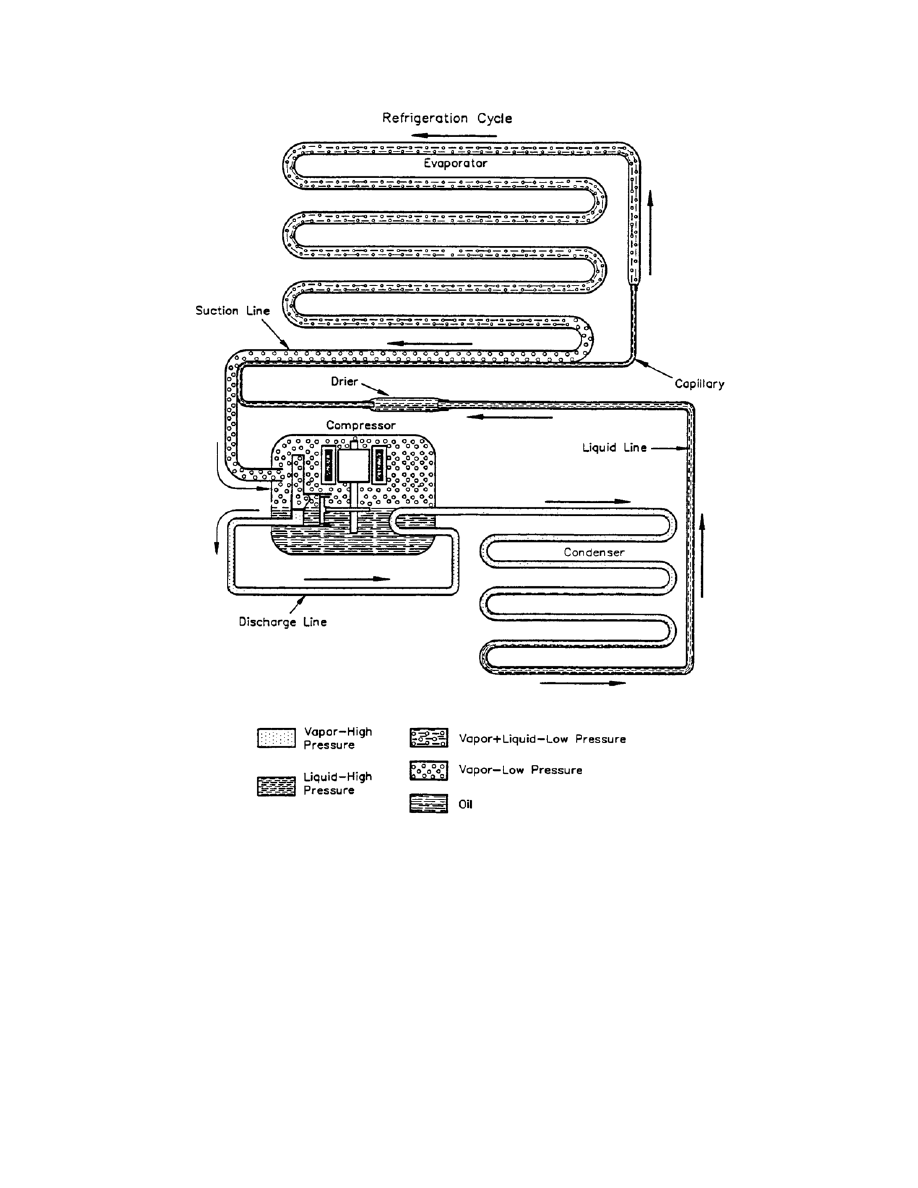
COMPONENTS OF A BASIC REFRIGERATION SYSTEM
Refer to figure 1-1. This figure illustrates the refrigeration system and the
location of the major components. The following paragraphs provide the functions of
the major components.
a. Evaporator. The evaporator boils or evaporates refrigerant. It changes the
state of the refrigerant from a liquid to vapor and absorbs heat.
b. Compressor. The compressor increases the vapor pressure and moves the
refrigerant. The types of compressors are hermetic, semihermetic, and open.
c. Condenser. The condenser condenses the refrigerant. It changes the state
of refrigerant from vapor to liquid and gives up heat to the atmosphere.
d. Flow Controls. The flow controls create a pressure difference and regulate
the quantity of refrigerant flow. Types of flow controls are as follows:
(1)
Capillary
tube. The inside diameter and length control the flow. This
tube is used on balanced manufactured units and only with hermetic compressors. It is
a simple and low cost method to control refrigerant flow. You must use an accumulator
strainer dryer with the capillary tube.
(2) High side float. This control is used in high volume centrifugal systems
and big chillers. It passes liquid but not vapor.
(3) Low side float. This control is generally used with ammonia systems.
(4) Automatic expansion valve. The valve applies constant pressure on the
evaporator and is commonly used on water fountains.
(5) Thermostatic expansion valve. The sensing bulb refrigerant in the bulb
is the same as the unit bulb on the evaporator.
MD0367 1-3
Figure 1-1. Basic refrigeration system.
1-3.
PREVENTIVE MAINTENANCE CHECKS AND SERVICES PROCEDURES
You perform preventive maintenance checks and services (PMCS) to ensure that
the refrigerator operates properly. All checks are performed before operation and
semiannually.
a. Operational Inspection/Test Procedures. While inspecting and testing the
refrigerator, you can discover malfunctions that require servicing. Follow these
procedures to inspect and test the refrigerator.

MD0367 1-4
CAUTION:
Under no circumstances should the refrigerator be laid on its front or
side. Flooring on which the refrigerator is to be situated must be free of
vibration and reasonably level.
(1) Check all exposed refrigeration lines to be sure they are not dented or
broken.
(2) Check the condenser fan for free rotation.
(3) Check the outer surface for dents, breaks or damage that could affect
the operation. If a break extends through outer surfaces into the interior of the unit,
request unit medical equipment maintenance support.
NOTE:
The equipment is not ready or available if a break extends through the outer
surfaces into the interior of the unit.
(4) Check the latches and hinges for tightness of attachment and smooth
operation. Ensure that when the door is closed, it provides a tight seal.
(5) Check the door gasket for cracks, cuts, or breaks.
(6) Check the interior of the unit for cracks or breaks in surfaces.
(7) Check that the shelves are present and in good condition.
(8) Check controls and gauges for damage that would prohibit the unit from
operating normally.
(9) Check the shock mount and foot assembly for damage and proper
operation.
(10) Check the grille front and back to ensure they are clean and do not
obstruct air flow.
(11) Check all exposed tubing connections of the refrigeration system for
leaks. Request unit medical equipment maintenance support if tubing is leaking,
(12) Check the power cord and plug for cracks, cuts, and exposed bare
wires. Check that the insulation has not been pulled away from plug or unit strain relief.
NOTE:
The equipment is not ready or available if there are bare wires exposed or
damaged prongs on the plug.
CAUTION:
Make certain that the cabinet is located so that the front grille opening is
unobstructed.

MD0367 1-5
(13) Connect the power cord to the correct power supply as indicated on the
unit identification plate.
NOTE:
The equipment is not ready or available if the unit fails to operate after
checking the fuse, or the unit starts and you notice unusual smells or noises.
NOTE:
Allow the unit to operate for several hours before checking that it is operating
within the proper temperature range set by the manufacturer.
(14) Check that the unit is operating within the temperature range set on the
refrigerator control.
(a) Hang an accurate thermometer next to the temperature sensing
bulb in the refrigerator.
(b) Ensure that the temperature reading on the temperature gauge
corresponds to the reading of the accurate thermometer inside the refrigerator.
NOTE:
The equipment is not ready or available if the unit fails to operate within the
manufacturer's specified temperature range.
(15) Put the unit into operation if no EQUIPMENT IS NOT
READY/AVAILABLE condition exists.
b. Manifold Gas and Pressure Test. To perform the manifold gas and
pressure test, follow these procedures.
(1) Connect the blue hose from the low side gauge to the suction access
(vacuum on gauge).
(2) Connect the red hose from the high side gauge to the high side access.
(3) Connect the yellow hose from the center on the manifold to the Freon
tank.
(4) Open the Freon valve.
(5) Loosen the red and blue hoses at the access valves. Crack open the
valves at the manifold to purge air from the hoses.
(6) Tighten the hoses and open the valves on the refrigerator and at the
manifold until the pressure on both gauges equalize.
(7) Test for leaks.
(a) Spray a soap solution on the joints.

MD0367 1-6
(b) Add dye to the system to detect very small and hard to detect
leaks.
(c) Use a halide torch to locate leaks.
1 Use the torch to heat the copper element until it is cherry red.
2 Move the hose over the system. A change of color indicates a
leak.
a Pale blue--no leaks.
b Yellow-green--small leak.
c Purplish-blue--large leak.
(d) Use an electronic leak detector. Follow the manufacturer's
instructions.
c. System Evaporation.
(1) Connect the manifold gauges.
(a) Connect the blue hose from the compound gauge to the suction
access valve.
(b) Connect the red hose from the high side gauge to the high side
access valve.
(c) Connect the yellow hose from the center on the manifold to the
vacuum pump.
(2) Check the oil in the vacuum pump.
(3) Open both valves on the manifold.
(4) Read the instructions for the pump you are using.
(5) Start the vacuum pump.
(6) Run the vacuum pump until the gauge reads 25 inches to 27 inches
vacuum (the time depends on the size of the system).
(7) Close both valves on the manifold.
(8) Turn off the vacuum pump per the instructions on the pump.

MD0367 1-7
(a) Leave everything hooked up and see if the compound gauge rises.
1 Retighten all hose fittings if the gauge rises.
2 Repeat the leak check if the gauge continues to rise.
(b) Determine the system is good to charge if the pressure holds for 15
minutes.
d. System Vapor Charge.
(1) Connect the manifold gauges.
(a) Connect the blue hose from the compound gauge to the suction
access valve.
(b) Connect the red hose from the high side gauge to the high side
access valve.
(c) Connect the yellow hose from the center on the manifold gauge to
the tank of Freon.
(2) Open the valve on the tank (make sure the tank is upright).
(3) Open both valves at the manifold (this allows vapor to enter both high
and low sides).
(4) Release the pressure to equalize at the gauges.
(5) Close both valves on the manifold.
(6) Start the compressor by plugging in the refrigerator.
(7) Let the system stabilize to check the desired pressure (open the low side
valve on the manifold to add Freon).
(8) Continue to add Freon in this manner until you reach the desired
pressures.
(a) High side 110 to 140 pounds per square inch (psi).
(b) Low side 5 to -5 psi.
CAUTION: Never add liquid refrigerant to a system as you will flood the system and
damage the compressor and other components.

MD0367 1-8
1-4. TROUBLESHOOTING
PROCEDURES
General troubleshooting information for locating and correcting many of the
operating malfunctions which may develop in the refrigerator are listed in the
troubleshooting guide in the appendix. Because local units do not have Freon recovery
systems, they do not remove and replace components once they isolate a malfunction.
Also, you cannot cut lines carrying Freon because it may cause a Freon leak. Only in a
combat situation are you permitted to make repairs which allow Freon leaks.
1-5.
COPPER TUBING REPAIR
a. Flare the Tubing.
(1) Cut off 1 or 2 inches of copper tubing from stock copper tubing.
(2) Remove any burrs from the copper tubing by using the reamer or cutter.
(3) Place the copper tubing piece in the flaring tool block with about 1/16
inch of the tubing (about the thickness of a nickel) above the flaring tool block.
(4) Lubricate the flaring tool threads with oil to obtain better performance of
the tool.
(5) Position the flaring tool over the copper tubing on the flaring tool block.
(6) Compress the copper tube solidly against the counter-sunk recess of the
flaring tool block by turning the flaring tool handle clockwise (CW).
NOTE:
Too much pressure may split the flare, and too little pressure will not make
the flare wide enough. A lopsided flare results from flaring out-of-round
tubing.
(7) Remove the flaring tool from the copper tubing.
(8) Remove the copper tubing from the flaring tool block and check the flare
for defects.
(a) The flare wall thickness should be equal all around.
(b) The flare should drag easily through the flare nut.
b. Swage the Tubing.
(1) Cut off 1 or 2 inches of copper tubing from stock copper tubing.
(2) Remove any burrs from the copper tubing by using the reamer on cutter.

MD0367 1-9
(3) Place the copper tubing piece in the flaring tool block with the tubing
extending out from the block at least equal to the outside diameter of the tubing plus 1/4
inch.
(4) Place the flaring tool with the right size adaptor into position over the
tubing and flaring tool block.
(5) Turn the flaring tool handle CW until the adaptor is into the tubing all the
way (equal to the diameter of the tubing).
NOTE:
Do not screw the flaring tool too far down or you will smash the tubing.
(6) Remove the flaring tool from the copper tubing.
(7) Remove the copper tubing from the tool block and check the for defects.
(8) Check to see if the copper tubing will fit into the swage area.
c. Solder the Tubing.
(1) Ignite the solder torch.
(a) Open the valve on the tank 1/2 turn counter-clockwise (CCW)
(right-handed threads) using a refrigeration wrench. Leave the wrench on the tank.
NOTE:
You use a refrigeration wrench because it has the right size hole for the tank,
and it will not strip the valve on the tank.
(b) Turn the handle on the regulator 1 to 2 turns CW (left-handed
threads).
(c) Use a soap solution to check for leaks around the regulator.
(d) Turn the on/off knob on the torch head CCW to allow gas flow.
(e) Light the torch by holding the torch igniter 1 to 2 inches away from
the tip and strike the igniter until the torch is lit. Keep the lighted torch tip pointing away
from gas tanks, personnel, and yourself.
(f)
Adjust the torch flame by turning the regulator knob. The flame
should be about 1 inch in length at the tip of the blue flame.
(2) Extinguish the torch.
(a) Turn the on/off knob on the torch head CW to stop gas flow.

MD0367 1-10
(b) Turn the regulator knob on the tank CCW (all the way out).
(c) Turn off the tank by turning the valve CW.
(3) Solder a swage joint with 25 percent to 45 percent silver solder.
(a) Obtain copper tubing pieces prepared for swaging and clean the
inside of the swage tubing and the outside portion of the other piece using crocus cloth.
NOTE:
After you clean them, do not touch the clean surfaces with your fingers
because the oil from your fingers will get on the tubing, and the solder will not
adhere to it.
(b) Position the two pieces of tubing together and secure them in a
vise.
(c) Apply the 25 percent silver solder flux all around the joint using a
flux brush.
(d) Bend a piece of 25 percent silver solder about 1/2 inch from the
end using pliers. (This is all you need to solder the joint.)
(e) Ignite the torch.
(f)
Point the flame at the center of overlapping joint. The blue tip of
the flame should be about 1/8 inch from the joint. This will heat both pieces of tubing
equally.
(g) Move the flame around the joint. When the tubing becomes red
hot, touch the solder to the opposite side of the flame. The solder will melt and flow
around the joint when joint is hot enough.
(h)
Extinguish
torch.
(i)
Obtain a professional appearance on the soldered joint by wiping
the joint with a wet rag to cool the joint and remove the flux.
(4) Solder a swage joint with 15 percent silver solder or silver braze.
(a) Obtain copper tubing pieces prepared for swaging.
(b) Position the two pieces of tubing together and secure them in a
vise.
(c) Position a piece of 15 percent silver solder (flat stick) for soldering.

MD0367 1-11
(d) Ignite the torch.
(e) Point the flame at the center of the overlapping joint. The blue tip
of flame should be about 1/8 inch from the joint. This will heat both pieces of tubing
equally.
(f)
Move the flame around the joint and touch the solder to opposite
side of the flame. The solder will melt and flow around the joint when the joint is hot
enough.
(g)
Extinguish
torch.
(h) Obtain a professional appearance on the soldered joint by wiping
the joint with a wet rag to cool the joint and remove the flux.
1-6.
THERMOSTAT REMOVAL AND REPLACEMENT
a. Unplug the unit.
b. Open the door.
c. Locate the thermostat.
d. Remove the knob.
e. Remove the faulty thermostat.
f. Replace the faulty thermostat with a thermostat that functions.
g. Replace the knob.
h. Close the door.
i. Plug in the unit.
1-7.
THERMAL OVERLOAD DEVICE REMOVAL AND REPLACEMENT
a. Unplug the unit.
b. Locate the thermal overload detector.
c. Remove electrical connections.
d. Remove the malfunctioning thermal overload detector.

MD0367 1-12
e. Replace the malfunctioning thermal overload detector with one that operates
properly.
f. Replace the electrical connections.
g. Plug in the unit.
1-8.
COMPRESSOR REMOVAL AND REPLACEMENT
a. Unplug the unit.
b. Evacuate Freon from the system using a recovery system.
c. Disconnect the electrical connections from the compressor.
d. Cut the refrigeration tubing on the high and low side. It may be possible to
unsolder swage joints or disconnect flare fittings before cutting tubes.
e. Unbolt the compressor from the shock mounts.
f. Remove the compressor.
g. Connect the new compressor. It will be necessary to re-flare or swage new
fittings.
h. Silver solder the refrigeration connections.
i. Evacuate the system with a vacuum pump.
j. Charge the system with Freon.

MD0367 1-13
EXERCISES, LESSON 1
INSTRUCTIONS: Answer the following exercises by marking the lettered response that
best answers the question or best completes the sentence.
After you have answered all of the exercises, turn to "Solutions to Exercises" at
the end of the lesson and check your answers. For each exercise answered incorrectly,
reread the lesson material referenced with the solution.
1. Which of the following components gives up heat to the atmosphere?
a.
Condenser.
b.
Evaporator.
c.
Compressor.
d. Low side float.
2. Which of the following flow controls is commonly used on water fountains?
a. Low side float.
b. High side float.
c. Automatic expansion valve.
d. Thermostatic expansion valve.
3. When performing the manifold gas and pressure test, before you loosen the
hoses at the access valves to purge air from the hoses, you must:
a. Test for leaks.
b. Open the Freon valve.
c. Connect the manifold gauges.
d. Open the valves at the manifold.

MD0367 1-14
4. You are testing for leaks using the halide torch and observing changes of color.
Which color indicates a small leak?
a. Pale blue.
b.
Yellow-blue.
c.
Yellow-green.
d.
Purplish-blue.
5. When you vapor charge the system, you must connect the manifold gauges. You
connect the red hose from the high side gauge to the:
a.
Vacuum
pump.
b. Tank of Freon.
c. Suction access valve.
d. High side access valve.
Check Your Answers on Next Page

MD0367 1-15
SOLUTIONS TO EXERCISES, LESSON 1
1. a
(para 1-2c)
2. c
(para 1-2d(4))
3. b
(para 1-3b(4))
4. c
(para 1-3b(7)(c)2)
5. d
(para 1-3d(1)(b))
End of Lesson 1

MD0367 2-1
LESSON ASSIGNMENT
LESSON 2 Field
Sink
Maintenance.
TEXT ASSIGNMENT
Paragraphs 2-1 through 2-6.
TASKS TAUGHT
Perform Preventive Maintenance Checks and Services
on the Field Sink.
LESSON OBJECTIVES
When you have completed this lesson, you should be
able
to:
2-1. Identify the location of the components.
2-2. Identify PMCS procedures.
SUGGESTION
Work the lesson exercises at the end of this lesson
before beginning the next lesson. These exercises will
help you accomplish the lesson objectives.
MD0367 2-2
LESSON 2
FIELD SINK MAINTENANCE
2-1. GENERAL
The field sink unit consists of a collapsible, portable scrub sink that is capable of
delivering either electrically heated or unheated water. This sink unit is for medical
personnel to use in the field during pre-operative and post-operative scrub and for
cleaning instruments.
2-2. SPECIFICATIONS
You must know the operating specifications for the field sink to ensure that the
sink is operating properly. Refer to figure 2-1 for a listing of the general specifications.
Figure 2-2 provides performance specifications.
Line Voltage (ac)
Flow and Start Delay
Spare Fuses
Spare Washers
115 volts (v), 60 Hertz (Hz)
Continuous flow within 30 seconds of
activating the pump.
Two
Six
Figure 2-1. General specifications.
Heater Performance (Pump)
Knee Lever Left (Activate)
Knee Lever Middle
Knee Lever Right
Ambient Water
Flow Rate (Qt/Min)
1.8 ± 0.1
1.2 ± 0.1
0.8 ± 0.1
Temperature (F)
95º +5º -2º
105º ± 3º
120º +2º -5º
70º +0º -2º
Heater Performance (Gravity)
Flow Rate (Qt/Min)
1.5 ± 0.1
2.2 ± 0.1
Temperature (F)
98º ± -3º
89º ± -3º
Figure 2-2. Heater performance specifications.

MD0367 2-3
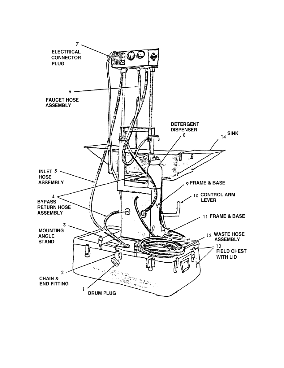
2-3. SINK
COMPONENTS
The sink consists of three major components. The following paragraphs describe
the components. Refer to figure 2-3.
a. Base Section. The parts in the base section serve a dual purpose. The
pieces provide a carrying case for all the other components when the unit is transported
or stored. When the sink is assembled for use, these parts provide a base and
reservoir for the unit. A grounding strap and clamp, the knee controlled valve, and
related hoses and fittings are located in the base section. See item 13 in figure 2-3.
b. Sink Section. The parts in the sink section in figure 2-3 are the sink (item
14), a detergent dispenser (item 8), a faucet (item 6), and the necessary hoses and
fittings.
c. Power Unit. The power unit is connected through wiring and hoses to the
sink and base sections. It is supported by extension rods. Located externally on the
power unit is an indicator light, the heat and pump controls, a fuse holder, a selector
valve handle, a demountable fan, and fittings for various connecting lines. Located
within the power unit is a water mode selector valve, a terminal block, a water heater,
water, and the necessary interconnecting plumbing fittings.
2-4. ASSEMBLY
PROCEDURES
The sink is packed in a disassembled form within a field chest (item 13 in figure
2-3). The field chest provides a sturdy, reinforced carrying, shipping, and storage case.
If the case is in good condition, it is a water tight case. To assemble the sink, perform
the procedures in the following paragraphs.
a. Mechanical Assembly.
(1) Place the field chest upside down (lid secured).
(2) Release the chest latches and lift the chest bottom from the lid. (The
scrub sink components remain with the lid.)
(3) Release the restraining strap from the power unit. Release the catches
and remove the power unit from the lid.
(4) Release the restraining strap from the sink assembly. Remove the sink
from the lid, exposing the remaining components.
(5) Release the straps retaining the sink components. Note the location of
these items for repacking purposes.
(6) Remove all components from the lid. Lay them on a clean surface.
MD0367 2-4
Figure 2-3. Sink unit (rear view).

MD0367 2-5
(7) Secure all restraining straps within the lid.
(8) Replace the lid on the chest and latch it securely.
(9) Swing the stand mounting angles into position. Secure the braces with
wing nuts and attach them to the field chest lid.
(10) Position the stand assembly.
(11) Attach the sink assembly using the latches.
(12) Snap the tray assemblies and tray leg brackets into place on either side
of the sink assembly.
(13) Position the extension rods on the extension of the stand assembly.
(14) Position the faucet through the bracket on the rear of the sink. Lock it in
place with a thumbscrew.
(15) Attach the detergent dispenser. Clip its dispensing spout to a bracket on
the stand. Attach the clear hose on the rubber base to the underside of the soap
dispenser and lay the rubber base (foot pump) in front of the sink assembly.
(16) Position the power unit on the extension rods.
(17) Connect the hoses.
(18) Fill the reservoir.
NOTE:
Disassemble in the reverse sequence.
b. Electrical Installation. The electrical installation involves making the ground
and electrical connections as described in the following paragraphs
(1) Make the ground connection.
(a) Remove the binding around the wire braid and stretch it out.
(b) Locate a proper ground, such as a water pipe. Tighten the clamp
to the pipe.
(c) Check the ground connection between the sink assembly frame
and the grounding object.
CAUTION:
Put all switches in the OFF position before connecting the sink unit to a
power
source.

MD0367 2-6
(2) Make the electrical connection.
(a) Use an electrical receptacle supplying the required voltage.
(b) Ensure that the receptacle is located at least five feet above the
ground or floor. Make sure the receptacle is properly grounded and designed to accept
a three-prong plug from the sink.
CAUTION:
Fill the chest reservoir or connect to a suitable water supply before
making any pump or heater operational checks.
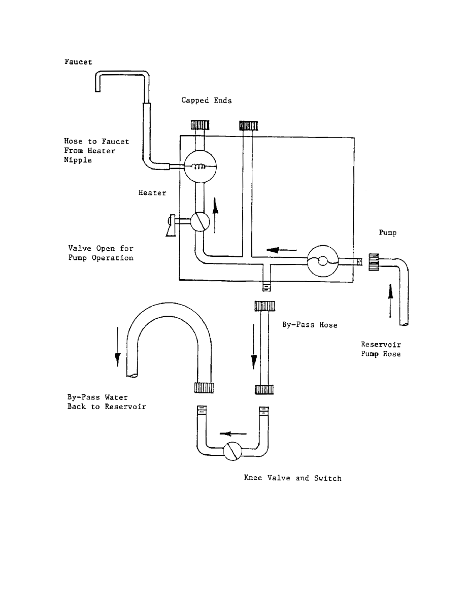
2-5. OPERATIONAL
CHECKOUTS
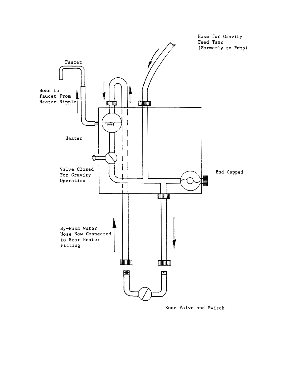
Refer to figures 2-4 and 2-5 for illustrations of pump operation flow and gravity
feed control. After the sink is assembled, you perform an operational checkout. This
includes checking the pump and heater. Perform the procedures in the following
paragraphs.
a. Operational Checkout of the Pump.
(1) Put the plug valve handle in the PUMP position.
(2) Move the toggle switch labeled pump to the ON position.
(3) Move the knee lever to the right (activated) position. The water should
begin to flow within 30 seconds.
b. Operational Checkout of the Heater.
(1) Move the toggle switch labeled heater to the ON position.
(2) Move the knee operated lever to the activated position (right).
(3) Ensure that the heater is on and the indicator light lights.
(4) Inspect the unit for cleanliness and corrosion. Clean the unit if
necessary.
(5) Inspect all hoses and clamps. Replace cracked or deteriorated hoses.
(6) Inspect the electrical components. Clean any components that are
corroded.
(7) Inspect wires for brittle or cracked insulation.
MD0367 2-7
Figure 2-4. Pump operation flow.
MD0367 2-8
Figure 2-5. Gravity feed flow.

MD0367 2-9
2-6. PREVENTIVE
MAINTENANCE CHECKS AND SERVICES
You perform PMCS to ensure the sink operates properly when needed. The
following paragraphs describe the procedures.
a. Inspect the Power Unit Assembly.
(1) Remove power from the unit.
(2) Remove the cover from the assembly.
(3) Ensure that the volume of water flow meets the specifications.
(4) Check all lines for leaks.
b. Test the Fuse.
(1) Remove the fuse from the fuse holder.
(2) Test the fuse using a digital multimeter (DMM). Test for approximately
zero ohms.
CAUTION:
Fill the reservoir or connect a water supply to the pump BEFORE
performing an operational check.
c. Check the Pump.
(1) Assemble the unit.
(2) Prime the pump.
(3)
Apply
power.
(4) Test the pump.
(a) Put the plug valve handle in the PUMP position.
(b) Move the toggle switch labeled PUMP to the ON position.
(c) Move the knee lever to the right (activated) position. Water should
begin to flow within thirty seconds. If the water does not flow, troubleshoot for the
problem.
(d) Ensure that the volume of control is within the specifications.
(e) With the pump operating, check all lines for leaks.

MD0367 2-10
d. Inspect and Test the Fan.
(1) Remove the assembly cover.
(2) Inspect the fan for cleanliness. Clean it if necessary.
(3) Inspect the wires for signs of deterioration.
(4) Apply power to the fan and verify that it operates.
e. Test the Heater.
(1) Prime the pump.
(2)
Apply
power.
(a) Toggle the switch labeled HEATER to the ON position.
(b) Move the knee-operated lever to the activated position (right). This
will supply power to the heater.
(c) Ensure that the indicator light lights to indicate the heater is
operating. Ensure the water heats to temperatures shown in the specifications.
f. Inspect the Lamp. Verify that the lamp operates when the unit is energized.
g. Inspect the Hose Assembly. Inspect all hoses for leaks and signs of
deterioration.
h. Inspect the Washers. Visually inspect washers for signs of deterioration.
i. Inspect the Surgical Detergent Dispenser. Visually check for cracks,
leaking, and deterioration.
j. Inspect the Lever Control. Check for looseness, binding, and proper
operation.
k. Test the Cam Micro Switch. Rotate the lever control. Verify that the pump
energizes, and the heater works when activated.

MD0367 2-11
EXERCISES, LESSON 2
INSTRUCTIONS: Answer the following exercises by marking the lettered response that
best answers the question or best completes the sentence.
After you have answered all of the exercises, turn to "Solutions to Exercises" at
the end of the lesson and check your answers. For each exercise answered incorrectly,
reread the lesson material referenced with the solution.
1. You are reviewing the specifications for the field sink. What is the acceptable line
voltage
(ac)?
a.
110v.
b.
115v.
c.
120v.
d.
140v.
2. You are reviewing the specifications for heater performance of the pump. What is
the acceptable flow rate (quarts per minute) when using the left knee lever?
a.
2.8
+ 0.1.
b.
2.3
+ 0.1.
c.
1.8
+ 0.1.
d.
1.3
+ 0.1.
3. You are reviewing the specifications for heater performance during a gravity
operation. The flow rate is 1.5 quarts per minute. What should the approximate
temperature of the water be?
a.
98ºF.
b.
108ºF.
c.
112ºF.
d.
120ºF.

MD0367 2-12
4. You are performing an operational checkout of the pump. You activate the pump
by moving the knee lever to the:
a.
Left
position.
b.
Middle
position.
c.
Back
position.
d.
Right
position.
5. When you test the heater, which of the following tasks do you perform?
a. Ensure that the water begins to flow within thirty seconds after the pump is
activated.
b. Inspect the surgical detergent dispenser.
c. Inspect the fan for cleanliness.
d. Prime the pump.
Check Your Answers on Next Page

MD0367 2-13
SOLUTIONS TO EXERCISES, LESSON 2
1. b
(figure 2-1)
2. c
(figure 2-2)
3. a
(figure 2-2)
4. d
(para 2-5a(3))
5. b
(para 2-6e(1))
End of Lesson 2
MD0367 A-1
APPENDIX
TROUBLESHOOTING GUIDE FOR THE REFRIGERATOR
SYMPTOM
1. Compressor will not
start; no hum.
2. Compressor will not
start; hums, but trips on
overload protector.
PROBABLE CAUSE
Line switch open.
Fuse removed or blown.
Overload protector tripped.
Control stuck in open
position.
Control off due to cold
location.
Wiring improper or loose.
Low voltage to unit.
Starting capacitor
defective.
Relay failing to close.
Compressor motor has a
winding open or shorted.
Internal mechanical
trouble in compressor.
Improperly wired.
CORRECTIVE ACTION
Close switch; test/replace
switch.
Replace fuse.
Test and replace, if
required.
Test, repair, or replace
control.
Adjust control.
Check wiring against
diagram and repair.
Troubleshoot electrical
circuit and correct.
Replace capacitor.
Determine reason and
correct; replace if
necessary.
Replace compressor.
Replace compressor.
Check wiring against
diagram and repair.

MD0367 A-2
SYMPTOM
3. Compressor starts, but
does not switch off from
start winding.
4. Compressor starts and
runs, but short cycles on
overload protector.
PROBABLE CAUSE
Low voltage to unit.
Relay fails to open.
Run capacitor is defective.
Excessively high
discharge pressure.
Compressor motor has a
winding open or shorted.
Internal mechanical
trouble in compressor
(tight).
Improperly wired.
Excessive discharge
pressure.
Low voltage to unit.
Overload protector
defective.
Run capacitor defective.
Compressor too hot; return
gas hot.
CORRECTIVE ACTION
Troubleshoot electrical
circuit and correct.
Determine reason and
repair or replace relay.
Replace run capacitor.
Check discharge shut-off
valve for possible
overcharge or insufficient
cooling of the condenser.
Replace compressor.
Replace compressor.
Check wiring against
diagram and repair.
Ensure the ventilation is
adequate and remove
restrictions in refrigeration
lines.
Troubleshoot electrical
circuit and correct.
Replace protector.
Replace capacitor.
Check refrigerant charge;
fix leak; add refrigerant as
required.
MD0367 A-3
SYMPTOM
4. (Compressor starts and
runs, but short cycles on
overload protector--
Continued)
5. Unit runs ok, but short
cycles.
PROBABLE CAUSE
Suction pressure too high.
Compressor motor has a
winding shorted.
Excessive current passing
through overload
protector.
Overload protector.
Thermostat.
High pressure cut-out due
to insufficient circulation.
High pressure cut-out due
to refrigerant overcharge.
High pressure cut-out due
to air in system.
Low pressure cut-out due
to liquid line solenoid
leaking.
Low pressure cut-out due
to compressor valve leak.
Low pressure cut-out due
to undercharge.
Low pressure cut-out due
to restriction in expansion
device.
CORRECTIVE ACTION
Check refrigeration cycle.
Replace compressor.
Check wiring diagram;
check possible incorrect
connection of fan motors,
lamps, or heater, and
correct.
Replace defective
protector.
Adjust differential.
Check air supply to
condenser; correct
problem.
Reduce charge.
Purge air from system;
add refrigerant, as
required.
Repair line.
Replace valve.
Fix leak, add refrigerant.
Replace device.
MD0367 A-4
SYMPTOM
6. Unit operates long or
continuously.
PROBABLE CAUSE
Shortage of refrigerant.
Control contacts stuck or
frozen.
Refrigerated or air-
conditioned space has
excessive heat load or
poor insulation.
Dirty condenser.
Evaporator coil iced.
Restriction in refrigeration
system.
Filter dirty.
Run capacitor open,
shorted, or blown.
Excessively high line
voltage (110% of rated
maximum).
Incorrect run capacitor.
Relay contacts do not
open properly.
CORRECTIVE ACTION
Fix leak; add refrigerant.
Clean contacts or replace
control.
Determine fault and
correct.
Clean condenser.
Defrost. Check defrost
circuit.
Determine location and
remove.
Clean or replace filter.
Replace capacitor.
Determine reason and
correct.
Replace with proper
capacitor.
Clean contacts and
replace relay, if required.
MD0367 A-5
SYMPTOM
7. Prolonged operation on
start cycle.
8. Space temperature too
high.
9. Suction line frosted or
sweating.
PROBABLE CAUSE
Start capacitor open,
shorted, or blown.
Relay mounted incorrectly.
Relay being influenced by
loose or vibrating
mounting.
Prolonged operation on
start cycle due to high
starting load.
Control setting too high.
Environmental control unit
(ECU) temperature too
high.
Inadequate air circulation.
Expansion valve passing
excess refrigerant.
Expansion valve stuck
open.
Evaporator fan not
running.
Overcharge of refrigerant.
CORRECTIVE ACTION
Replace capacitor.
Remount relay in correct
position.
Remount rigidly.
Correct by using pump
down arrangement, if
necessary.
Reset control.
Adjust ECU.
Improve air movement.
Replace valve.
Replace valve.
Test fan motor; replace fan
motor, if required.
Correct charge.
MD0367 A-6
SYMPTOM
10. Liquid line frosted or
sweating.
11. Unit noisy off line.
12. Unit cools but does
not get to set point.
13. Surveillance module
upper solution light
emitting diode (led)
lamp off; displayed
temperature correct.
14. Surveillance module
lower solution led
lamp off when selection
pushbutton switch
depressed; displayed
temperature correct.
PROBABLE CAUSE
Restriction in filter drier.
Liquid shut-off (king valve)
partially closed.
Loose parts or mountings.
Tubing rattling.
Bent fan blade causing
vibration.
Fan motor bearing worn.
Fan not operating.
Led lamp defective.
Led circuit defective.
Switch defective.
Led lamp defective.
Led circuit defective.
CORRECTIVE ACTION
Replace filter drier.
Open valve fully.
Find loose parts or
mountings and tighten.
Reform tubing so that it is
free of contact.
Replace blade.
Replace bearings or
motor, if required.
Check fan motor and
circuits. Replace motor if
required.
Replace led lamp.
Determine reason and
repair.
Test and replace if
required.
Replace led lamp.
Determine reason and
correct.

MD0367 A-7
SYMPTOM
15. Surveillance module
displayed incorrect
temperature; led
lamps onor off and
pushbutton Selection
switch notdepressed or
depressed momentarily.
16. Door status led lamp
constantly on or flashing
and monitor section
audible alarm constantly
on or pulsing; door closed.
17. Door status led lamp
constantly on or
flashing; no audible
alarm; door open.
18. Door status led lamp
off; monitor section
audible alarm operating
correctly; door open.
PROBABLE CAUSE
Upper/lower solution
sensor disconnected.
Upper/lower solution
sensor defective.
Digital temperature
display defective.
Reset switch defective.
Door switch(es) defective.
Switch circuits defective.
Silence/reset switch
defective.
Switch or audible alarm
circuits defective.
Audible alarm defective.
Led lamp defective.
Circuit defective.
CORRECTIVE ACTION
Check and reconnect
sensor.
Replace sensor(s).
Replace display.
Replace switch.
Replace switch(es).
Determine reason and
correct.
Replace switch.
Determine reason and
correct.
Perform other tests
involving alarm and
replace, if required.
Replace lamp.
Determine reason and
correct.
MD0367 A-8
SYMPTOM
19. Monitor temperature
led safe lamp on; power
on led lamp on; Power
failure led lamp flashing;
audible alarm pulsing.
20. Monitor Temperature
led lamps off; power on led
lamp on; power failure led
lamp off; audible alarm off.
21. Monitor temperature
led lamps on; power on led
lamp on; power failure led
lamp off; audible alarm off.
22. Monitor temperature
led safe lamp off; power
on led lamp off; power
failure led lamp flashing;
audible alarm pulsing.
PROBABLE CAUSE
Battery condition low.
Monitor temperature led
lamp(s) defective.
Circuit defective.
Circuit(s) defective.
Battery test switch in off
(down) position.
CORRECTIVE ACTION
Replace the battery.
Replace lamp(s).
Determine reason and
correct.
Determine reason and
correct.
Place in up position.
End of Appendix
Document Outline
- DEVELOPMENT
- ADMINISTRATION
- TABLE OF CONTENTS
- INTRODUCTION
- LESSON 1
- REFRIGERATOR MAINTENANCE
- 1-1. HEAT REMOVAL
- 1-2. COMPONENTS OF A BASIC REFRIGERATION SYSTEM
- 1-3. PREVENTIVE MAINTENANCE CHECKS AND SERVICES PROCEDURES
- 1-4. TROUBLESHOOTING PROCEDURES
- 1-5. COPPER TUBING REPAIR
- 1-6. THERMOSTAT REMOVAL AND REPLACEMENT
- 1-7. THERMAL OVERLOAD DEVICE REMOVAL AND REPLACEMENT
- 1-8. COMPRESSOR REMOVAL AND REPLACEMENT
- EXERCISES
- SOLUTIONS
- REFRIGERATOR MAINTENANCE
- LESSON 2
- APPENDIX
Wyszukiwarka
Podobne podstrony:
Notes on the 3 inch gun materiel and field artillery equipment 1917
Effect of magnetic field on the performance of new refrigerant mixtures
Out of the Armchair and into the Field
Influence Of Magnetic Field On Two Phase Flow Convective Boiling Of Some Refrigerant Mixtures
Herbs Of The Field And Herbs Of The Garden In Byzantine Medicinal Pharmacy
Haisch On the relation between a zero point field induced inertial effect and the Einstein de Brogl
ZERO POINT FIELD AND INERTIA
Improve Your Punctuation and Grammar Marion Field 3rd ed How To Books 2009
Field, Ryan Gay Pride and Prejudice
Modanese Inertial Mass and Vacuum Fluctuations in Quantum Field Theory (2003)
Sobczyński, Marek Achievements of the Department of Political Geography and Regional Studies, Unive
Home and Garden Force Field
Simultaneously Gained Streak and Framing Records Offer a Great Advantage in the Field of Detonics
The US Army and Marine Corps Counterinsuring field manual
Magnetic and Electromagnetic Field Therapy
01 Principles of Heating and Refrigeration
Biofeedback and the Human Emergy Field by Keith Wakelam (2000)
więcej podobnych podstron